WO2021019626A1 - 内燃エンジンの制御方法および制御装置 - Google Patents
内燃エンジンの制御方法および制御装置 Download PDFInfo
- Publication number
- WO2021019626A1 WO2021019626A1 PCT/JP2019/029525 JP2019029525W WO2021019626A1 WO 2021019626 A1 WO2021019626 A1 WO 2021019626A1 JP 2019029525 W JP2019029525 W JP 2019029525W WO 2021019626 A1 WO2021019626 A1 WO 2021019626A1
- Authority
- WO
- WIPO (PCT)
- Prior art keywords
- valve timing
- intake
- intake valve
- internal combustion
- combustion engine
- Prior art date
- Legal status (The legal status is an assumption and is not a legal conclusion. Google has not performed a legal analysis and makes no representation as to the accuracy of the status listed.)
- Ceased
Links
Images



Classifications
-
- F—MECHANICAL ENGINEERING; LIGHTING; HEATING; WEAPONS; BLASTING
- F02—COMBUSTION ENGINES; HOT-GAS OR COMBUSTION-PRODUCT ENGINE PLANTS
- F02D—CONTROLLING COMBUSTION ENGINES
- F02D41/00—Electrical control of supply of combustible mixture or its constituents
- F02D41/0025—Controlling engines characterised by use of non-liquid fuels, pluralities of fuels, or non-fuel substances added to the combustible mixtures
- F02D41/0047—Controlling exhaust gas recirculation [EGR]
- F02D41/006—Controlling exhaust gas recirculation [EGR] using internal EGR
- F02D41/0062—Estimating, calculating or determining the internal EGR rate, amount or flow
-
- F—MECHANICAL ENGINEERING; LIGHTING; HEATING; WEAPONS; BLASTING
- F02—COMBUSTION ENGINES; HOT-GAS OR COMBUSTION-PRODUCT ENGINE PLANTS
- F02D—CONTROLLING COMBUSTION ENGINES
- F02D13/00—Controlling the engine output power by varying inlet or exhaust valve operating characteristics, e.g. timing
- F02D13/02—Controlling the engine output power by varying inlet or exhaust valve operating characteristics, e.g. timing during engine operation
- F02D13/0261—Controlling the valve overlap
-
- F—MECHANICAL ENGINEERING; LIGHTING; HEATING; WEAPONS; BLASTING
- F02—COMBUSTION ENGINES; HOT-GAS OR COMBUSTION-PRODUCT ENGINE PLANTS
- F02D—CONTROLLING COMBUSTION ENGINES
- F02D13/00—Controlling the engine output power by varying inlet or exhaust valve operating characteristics, e.g. timing
- F02D13/02—Controlling the engine output power by varying inlet or exhaust valve operating characteristics, e.g. timing during engine operation
- F02D13/0203—Variable control of intake and exhaust valves
- F02D13/0215—Variable control of intake and exhaust valves changing the valve timing only
-
- F—MECHANICAL ENGINEERING; LIGHTING; HEATING; WEAPONS; BLASTING
- F02—COMBUSTION ENGINES; HOT-GAS OR COMBUSTION-PRODUCT ENGINE PLANTS
- F02D—CONTROLLING COMBUSTION ENGINES
- F02D23/00—Controlling engines characterised by their being supercharged
-
- F—MECHANICAL ENGINEERING; LIGHTING; HEATING; WEAPONS; BLASTING
- F02—COMBUSTION ENGINES; HOT-GAS OR COMBUSTION-PRODUCT ENGINE PLANTS
- F02D—CONTROLLING COMBUSTION ENGINES
- F02D41/00—Electrical control of supply of combustible mixture or its constituents
- F02D41/0002—Controlling intake air
-
- F—MECHANICAL ENGINEERING; LIGHTING; HEATING; WEAPONS; BLASTING
- F02—COMBUSTION ENGINES; HOT-GAS OR COMBUSTION-PRODUCT ENGINE PLANTS
- F02D—CONTROLLING COMBUSTION ENGINES
- F02D41/00—Electrical control of supply of combustible mixture or its constituents
- F02D41/0002—Controlling intake air
- F02D2041/001—Controlling intake air for engines with variable valve actuation
-
- F—MECHANICAL ENGINEERING; LIGHTING; HEATING; WEAPONS; BLASTING
- F02—COMBUSTION ENGINES; HOT-GAS OR COMBUSTION-PRODUCT ENGINE PLANTS
- F02D—CONTROLLING COMBUSTION ENGINES
- F02D2200/00—Input parameters for engine control
- F02D2200/02—Input parameters for engine control the parameters being related to the engine
- F02D2200/04—Engine intake system parameters
- F02D2200/0402—Engine intake system parameters the parameter being determined by using a model of the engine intake or its components
-
- F—MECHANICAL ENGINEERING; LIGHTING; HEATING; WEAPONS; BLASTING
- F02—COMBUSTION ENGINES; HOT-GAS OR COMBUSTION-PRODUCT ENGINE PLANTS
- F02D—CONTROLLING COMBUSTION ENGINES
- F02D2200/00—Input parameters for engine control
- F02D2200/02—Input parameters for engine control the parameters being related to the engine
- F02D2200/04—Engine intake system parameters
- F02D2200/0406—Intake manifold pressure
-
- F—MECHANICAL ENGINEERING; LIGHTING; HEATING; WEAPONS; BLASTING
- F02—COMBUSTION ENGINES; HOT-GAS OR COMBUSTION-PRODUCT ENGINE PLANTS
- F02D—CONTROLLING COMBUSTION ENGINES
- F02D2200/00—Input parameters for engine control
- F02D2200/02—Input parameters for engine control the parameters being related to the engine
- F02D2200/04—Engine intake system parameters
- F02D2200/0414—Air temperature
-
- F—MECHANICAL ENGINEERING; LIGHTING; HEATING; WEAPONS; BLASTING
- F02—COMBUSTION ENGINES; HOT-GAS OR COMBUSTION-PRODUCT ENGINE PLANTS
- F02D—CONTROLLING COMBUSTION ENGINES
- F02D41/00—Electrical control of supply of combustible mixture or its constituents
- F02D41/0002—Controlling intake air
- F02D41/0007—Controlling intake air for control of turbo-charged or super-charged engines
-
- F—MECHANICAL ENGINEERING; LIGHTING; HEATING; WEAPONS; BLASTING
- F02—COMBUSTION ENGINES; HOT-GAS OR COMBUSTION-PRODUCT ENGINE PLANTS
- F02D—CONTROLLING COMBUSTION ENGINES
- F02D41/00—Electrical control of supply of combustible mixture or its constituents
- F02D41/02—Circuit arrangements for generating control signals
- F02D41/04—Introducing corrections for particular operating conditions
- F02D41/10—Introducing corrections for particular operating conditions for acceleration
-
- Y—GENERAL TAGGING OF NEW TECHNOLOGICAL DEVELOPMENTS; GENERAL TAGGING OF CROSS-SECTIONAL TECHNOLOGIES SPANNING OVER SEVERAL SECTIONS OF THE IPC; TECHNICAL SUBJECTS COVERED BY FORMER USPC CROSS-REFERENCE ART COLLECTIONS [XRACs] AND DIGESTS
- Y02—TECHNOLOGIES OR APPLICATIONS FOR MITIGATION OR ADAPTATION AGAINST CLIMATE CHANGE
- Y02T—CLIMATE CHANGE MITIGATION TECHNOLOGIES RELATED TO TRANSPORTATION
- Y02T10/00—Road transport of goods or passengers
- Y02T10/10—Internal combustion engine [ICE] based vehicles
- Y02T10/12—Improving ICE efficiencies
Definitions
- the present invention provides a variable valve mechanism at least on the intake side, and is a control method and control device for an internal combustion engine that controls the amount of cylinder-filled air, which is the amount of air filled in the cylinder, by changing the valve timing of the intake valve. Regarding.
- the boost pressure and the in-cylinder in-cylinder are obtained both when the valve timing of the intake valve is advanced and when the valve timing is retarded. Predict supercharging efficiency from the amount of gas. Then, in the direction in which the predicted supercharging efficiency becomes higher, for example, when the supercharging efficiency in the case of advancing the angle becomes higher than in the case of retarding the angle, the valve timing of the intake valve is set in the advancing direction. Changes are disclosed (paragraphs 0007-0008).
- the intake valve timing that should be set as the target value is not constant throughout acceleration, but is transient, with the aim of further improving the control response of the cylinder filling air volume during acceleration to the target torque.
- the technology disclosed in JP2011-106339A is intended to optimize the supercharging efficiency with respect to the supercharging pressure and the amount of gas in the cylinder on the premise of application to a diesel engine, and is a transitional change. It does not correspond to the realization of the target intake valve timing that accompanies.
- An object of the present invention is to provide a control method and a control device for an internal combustion engine in consideration of the above problems.
- a control method for the internal combustion engine that controls the operation of the variable valve mechanism on the intake side during acceleration is provided.
- the relationship between the intake valve timing and the cylinder filling air amount is within a range in which the intake valve timing, which is the operation timing of the intake valve, can be advanced or retarded within a predetermined calculation cycle from the current value. Calculate the formula. Then, based on the operating state of the internal combustion engine, the target filling air amount, which is the target value of the cylinder filling air amount at the time of acceleration, is calculated, and the target filling air amount is calculated from the relational expression between the intake valve timing and the cylinder filling air amount. The target value of the intake valve timing with respect to the amount is calculated for each calculation cycle, and the command signal for the variable valve mechanism on the intake side is set based on the calculated target value of the intake valve timing.
- a control device for an internal combustion engine is provided.
- FIG. 1 is a schematic view showing an overall configuration of an internal combustion engine according to an embodiment of the present invention.
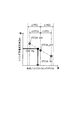
- FIG. 2 is a flowchart showing a basic flow of intake valve timing control according to the same embodiment.
- FIG. 3 is a flowchart showing the contents of the target intake valve timing setting process in the same intake valve timing control.
- FIG. 4 is an explanatory diagram showing the relationship between the valve timings of the intake valve and the exhaust valve and the residual gas ratio in the cylinder.
- FIG. 5 is an explanatory diagram showing the relationship between the valve timing of the intake valve and the amount of air filled in the cylinder, and schematically shows an example of the calculation process of the target intake valve timing.
- FIG. 6 is a time chart showing the operation of the internal combustion engine according to the embodiment of the present invention during acceleration.
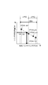
- FIG. 7 is an explanatory diagram showing the relationship between the valve timing of the intake valve and the amount of air filled in the cylinder, and schematically shows another example of the calculation process of the target intake valve timing.
- FIG. 1 shows the overall configuration of an internal combustion engine 1 according to an embodiment of the present invention.
- the internal combustion engine 1 (hereinafter referred to as “internal combustion engine”, sometimes simply referred to as “engine”) 1 according to the present embodiment is mounted on a vehicle and constitutes a drive source for the vehicle.
- the internal combustion engine 1 includes a turbocharger 2.
- the supercharger 2 includes an intake compressor 21 and an exhaust turbine 22, and the intake compressor 21 is interposed in the intake passage 11 of the internal combustion engine 1, and the exhaust turbine 22 is interposed in the exhaust passage 15.
- the intake compressor 21 and the exhaust turbine 22 are connected to each other by a shaft 23, and the exhaust turbine 22 receives the flow of exhaust air and its rotation is transmitted to the intake compressor 21 via the shaft 23, so that the intake compressor 21 and the exhaust turbine 22 are connected to each other. Rotates.
- an air cleaner (not shown) is installed in the introduction portion, a throttle valve 12 is installed on the downstream side of the intake compressor 21 with respect to the flow of the sucked air, and an intercooler 13 is installed on the further downstream side.
- the air cleaner removes foreign matter contained in the air sucked into the intake passage 11 from the atmosphere, and the throttle valve 12 can expand or reduce the substantially opening area of the intake passage 11.
- the main purpose of the throttle valve 12 is to adjust the pressure in the intake manifold (hereinafter referred to as "intake manifold pressure") rather than to control the intake air amount.
- the intercooler 13 cools the air compressed by the intake compressor 21.
- a fuel injection valve 14 is installed further downstream of the intercooler 13 so as to be able to supply fuel in the cylinder.
- the fuel injection valve 14 is embedded in the cylinder head 1B and injects fuel toward the intake port.
- the main body of the internal combustion engine 1 is divided into a cylinder block 1A and a cylinder head 1B, and the cylinder block 1A and the cylinder head 1B are coupled to each other.
- the space formed between the upper surface of the piston 31 inserted into the cylinder bore of the cylinder block 1A and the lower surface of the cylinder head 1B is the combustion chamber C.
- the intake passage 11 communicates with the combustion chamber C via the intake port of the cylinder head 1B
- the exhaust passage 15 communicates with the exhaust port of the cylinder head 1B, and the intake port receives intake air.
- a valve 32 and an exhaust valve 34 are installed in the exhaust port so that each port can be opened and closed.
- variable valve mechanism 33 and 35 respectively, in terms of operation timing, that is, valve timing.
- a variable valve mechanism 33 provided on the intake side
- a variable valve mechanism 35 provided on the exhaust side. Is configured so that the operating central angle between the opening and closing times can be changed while the operating angle, which is the crank angle from the opening time to the closing time, is constant.
- the operating central angle of the intake valve 32 is defined as “intake valve timing”
- the operating central angle of the exhaust valve 34 is defined as “exhaust valve timing”.
- the “valve timing” is not limited to this, and depending on the configuration of the variable valve mechanisms 33 and 35, the intake valve 32 or the exhaust valve 34 can be opened or closed. Is. That is, the “valve timing” indicates the position of the opening period of the intake valve 32 or the exhaust valve 34 relative to a specific crank angle (for example, exhaust top dead center).
- the cylinder head 1A is provided with a spark plug 36 on the cylinder central axis Ax.
- the spark plug 36 is installed so that the plug gap faces the combustion chamber C, and ignites and ignites the mixture of fuel and air formed in the combustion chamber C.
- an exhaust purification device 41 is installed on the downstream side of the exhaust turbine 22 with respect to the flow of exhaust gas discharged from the combustion chamber C, and a muffler (not shown) is installed further on the downstream side.
- the exhaust gas purification device 41 has a built-in catalyst for exhaust gas purification.
- the internal combustion engine 1 further includes an EGR system (not shown) that recirculates the exhaust gas after combustion as EGR gas into the cylinder.
- EGR system (not shown) that recirculates the exhaust gas after combustion as EGR gas into the cylinder.
- the exhaust passage 15 on the downstream side of the exhaust turbine 22 and the intake passage 11 on the upstream side of the intake compressor 21 are provided with an EGR passage, and the exhaust gas is recirculated through the EGR passage.
- Adopt a type EGR system.
- the engine controller 101 is configured as an electronic control unit, and includes a central processing unit (CPU), various storage devices such as RAM and ROM, and a microcomputer provided with an input / output interface and the like.
- CPU central processing unit
- RAM random access memory
- ROM read-only memory
- microcomputer provided with an input / output interface and the like.
- the engine controller 101 inputs detection signals of various operating state sensors that detect the operating state of the internal combustion engine 1, periodically executes a predetermined calculation based on the detected operating state, and fuels the internal combustion engine 1. Set the injection amount, fuel injection timing, intake valve timing, exhaust valve timing, ignition timing, etc.
- the accelerator sensor 111 that detects the amount of operation of the accelerator pedal by the driver (hereinafter referred to as “accelerator opening”) APO
- the rotation speed sensor 112 that detects the rotation speed NE of the internal combustion engine 1
- a cooling water temperature sensor 113 for detecting the temperature TW of the engine cooling water
- an intake manifold pressure sensor 114 for detecting the temperature TW of the engine cooling water
- an intake manifold pressure sensor 114 for detecting the temperature TW of the engine cooling water
- an intake manifold pressure sensor 114 for detecting the temperature TW of the engine cooling water
- an intake manifold pressure sensor 114 for detecting the temperature TW of the engine cooling water
- an intake manifold pressure sensor 114 for detecting the temperature TW of the engine cooling water
- an intake manifold pressure sensor 114 for detecting the temperature TW of the engine cooling water
- an intake manifold pressure sensor 114 for detecting the temperature TW of the engine cooling water
- an intake manifold pressure sensor 114 for
- the intake manifold pressure sensor 114 detects the air pressure in the manifold portion of the intake passage 11 as the intake manifold pressure Pmani_i, and the intake manifold temperature sensor 115 determines the temperature of the air in the manifold portion of the intake passage 11 as the intake manifold temperature Tmani_i. Detect as.
- the exhaust manifold pressure sensor 116 detects the exhaust pressure in the manifold portion of the exhaust passage 15 as the exhaust manifold pressure Pmani_e, and the exhaust manifold temperature sensor 117 detects the exhaust temperature in the manifold portion of the exhaust passage 15 as the exhaust manifold temperature Tmani_e. Detect as.
- the cylinder filling air amount Quint which is the amount of air filled in the cylinder for each combustion cycle, is controlled for the target value or the required value of the engine torque according to the accelerator opening APO. Then, when controlling the cylinder filling air amount Qint, the intake valve timing VTCint is changed, and at the same time, the intake manifold pressure Pmani_i is adjusted. The intake valve timing VTCint is changed by operating the intake VTC33, and the intake manifold pressure Pmani_i is adjusted by operating the throttle valve 12.
- the intake valve timing control according to the present embodiment is generally as follows.
- FIG. 6 shows the operation of the internal combustion engine 1 according to the present embodiment during acceleration by changes in the cylinder filling air amount Quint, the intake valve timing VTCint, and the intake manifold pressure Pmani_i with respect to the monotonous increase in the accelerator opening APO. ..
- the inclination of each parameter such as the accelerator opening APO with respect to the time t gives priority to easy understanding, and does not depend on the actual scale.
- target filling air amount Qint_trg for realizing the required torque of the internal combustion engine 1 is calculated.
- the basic value of the intake valve timing that can realize the target filled air amount Quint_trg in the steady state (hereinafter referred to as "basic intake valve timing").
- VTCint_0 and the basic value of the intake manifold pressure (hereinafter referred to as “basic intake manifold pressure") Pmani_0 are calculated.
- the basic intake valve timing VTCint_0 is temporarily delayed with respect to the monotonous increase in the accelerator opening APO and the required engine torque due to the relative relationship between the position of the piston 31 and the opening period of the intake valve 32. After making a corner, advance it.
- the basic intake manifold pressure Pmani_0 is increased in accordance with the change in the basic intake valve timing VTCint_0.
- the basic intake valve timing VTCint_0 is caused by temporarily retarding the basic intake valve timing VTCint_0 before advancing to the change of the actual value (hereinafter referred to as "actual intake valve timing") VTCint_act of the intake valve timing VTCint with respect to the basic intake valve timing VTCint_0.
- actual intake valve timing the basic intake manifold pressure Pmani_0 is corrected.
- This correction generally sets a target value (hereinafter referred to as "target intake manifold pressure") Pmani_trg of the intake manifold pressure Pmani_i, which is larger than the basic intake manifold pressure Pmani_0, with respect to the shortage of the actual intake valve timing VTCint_act with respect to the basic value VTCint_0. by.
- target intake manifold pressure Pmani_trg of the intake manifold pressure Pmani_i
- the actual value of the intake manifold pressure Pmani_i (hereinafter referred to as "actual intake manifold pressure") Pmani_act is delayed due to a response delay in the air system on the downstream side of the throttle valve 12.
- the target intake valve timing is adjusted by adjusting the intake valve timing VTCint away from the setting by the calculation map.
- VTCint_trg is set, and the cylinder filling air amount Quint is forcibly brought close to the target value Qint_trg.
- FIG. 2 shows the basic flow of intake valve timing control as the control executed by the engine controller 101
- FIG. 3 shows the specific contents of the target intake valve timing setting process (S106) in the intake valve timing control.
- the engine controller 101 is programmed to execute this control at predetermined calculation cycles (for example, 10 ms) after the power is turned on by the driver's key operation.
- the operating state of the internal combustion engine 1 is read.
- the read operating state includes intake manifold pressure Pmani_i, intake manifold temperature Tmani_i, exhaust manifold pressure Pmani_e, and exhaust.
- Manifold temperature Tmani_e, compression ratio Rcmp and EGR rate Regr are included.
- the target filling air amount Qint_trg is calculated.
- the basic exhaust valve timing VTCex_0 is calculated.
- the basic exhaust valve timing VTCex_0 is a basic value of the exhaust valve timing VTCex according to the operating state, and can be obtained by referring to the calculation map.
- the target intake valve timing VTCint_trg is set.
- the target intake valve timing VTCint_trg is set according to the procedure of the flowchart shown in FIG. 3 below.
- the actual intake manifold pressure Pmani_act is estimated. This estimation is based on considering the matching factor of the first-order lag with respect to the detected value of the intake manifold pressure sensor 114.
- the valve overlap amount which is the length of the period during which both the intake valve 32 and the exhaust valve 34 are opened, is limited.
- the exhaust valve timing VTCex is limited in S202 to 204
- the intake valve timing VTCint is limited in S207 to 209. Limit the amount of overlap.
- "Residual gas ratio in the cylinder" ⁇ rg means the ratio of the exhaust gas carried over from the previous cycle to the gas in the cylinder.
- target exhaust valve timing VTCex (hereinafter referred to as “target exhaust valve timing") so that the residual gas ratio ⁇ rg1 in the cylinder is kept within the upper limit value ⁇ th of the allowable range of the amount of residual gas.
- Limit VTCex_trg Limit VTCex_trg.
- FIG. 4 shows the relationship between the valve timings VTCint and VTCex of the intake valve 32 and the exhaust valve 34 and the residual gas ratio in the cylinder ⁇ rg.
- the residual gas ratio ⁇ rg in the cylinder tends to increase as the valve overlap amount increases as a general tendency.
- the residual gas ratio ⁇ rg in the cylinder increases with respect to the intake valve timing VTCint due to the change to the advance angle side as shown in FIG. 4 (A), and with respect to the exhaust valve timing VTCex. As shown in (B), it increases due to the change to the retard side.
- the relationship between the valve timing VTCex of the exhaust valve 34 and the residual gas ratio in the cylinder ⁇ rg is obtained in advance (FIG. 4 (B)), and the inside of the cylinder is obtained.
- the exhaust valve timing VTCex corresponding to the upper limit value ⁇ th of the residual gas ratio is calculated, and this is set as the limit value VTCex_lim of the exhaust valve timing. If the basic exhaust valve timing VTCex_0 obtained by reference from the calculation map is on the retard side beyond this limit value TCex_lim (S203), the final target exhaust valve timing VTCexh_trg is set to the limit value VTCexh_lim (S203). S204). On the other hand, when the basic exhaust valve timing VTCex_0 is on the advance side of the limit value TCexh_lim, the target exhaust valve timing VTCexh_trg is set to the basic exhaust valve timing VTCex_0.
- the delay generated in the actual intake manifold pressure Pmani_act is compensated by adjusting or correcting the target intake valve timing VTCint_trg.
- the deviation amount of the actual intake manifold pressure Pmani_act with respect to the target intake manifold pressure Pmani_trg (hereinafter referred to as “intake manifold deviation pressure”) ⁇ Pmani_i is calculated, and this indicates that the delay of the actual intake manifold pressure Pmani_act is remarkable. It is determined whether or not it is larger than the value ⁇ Pth.
- the intake manifold deviation pressure ⁇ Pmani_i is calculated by subtracting the actual intake manifold pressure Pmani_act from the target intake manifold pressure Pmani_trg.
- the process proceeds to S206, and if it is equal to or less than the predetermined value ⁇ Pth, the process proceeds to S207.
- the provisional value of the target intake valve timing VTCint_trg is set to the basic intake valve timing VTCint_0.
- the target intake valve timing VTCint_trg is calculated. Specifically, the following method is used.
- FIG. 5 shows the relationship between the intake valve timing VTCint and the cylinder filling air amount Qint.
- the air amount Qint is calculated on the vehicle, and the relational expression between the obtained plurality of points is calculated.
- a point corresponding to the current value VTCint_pre of the intake valve timing VTCint a point corresponding to the value VTCint_adv on the advance angle side, and a point corresponding to the value VTCint_rtd on the retard angle side are adopted.
- the calculation of the relational expression based on these points may be performed by, for example, connecting adjacent points or by approximating a probable straight line.
- complementation between two points (X 1 , Y 1 ) and (X 2 , Y 2 ) on the XY coordinates is performed by the following formula.
- the X coordinate corresponds to the target filling air amount Qint_trg
- the Y coordinate corresponds to the intake valve timing VTCint, respectively.
- the intake valve timing VTCint corresponding to the target filling air amount Qint_trg is calculated, and this is used as a provisional value of the target intake valve timing VTCint_trg.
- the calculation of the cylinder filling air amount Quint for the intake valve timing VTCint is based on the state in the intake passage 11 and the exhaust passage 15 under the substantial opening area defined for each port by the intake valve timing VTCint and the exhaust valve timing VTCex, and further. , It is possible to make a hydrodynamic calculation based on the state in the cylinder.
- engine rotation speed NE intake valve timing VTCint, exhaust valve timing VTCexh, intake manifold pressure Pmani_i, intake manifold temperature Tmani_i, exhaust manifold pressure Pmani_e, exhaust manifold temperature Tmani_e, compression ratio Rcmp, EGR rate Regr and cooling water.
- the cylinder filling air amount Qint is calculated based on the temperature TW.
- the following is an example of a calculation method applicable to the calculation of the cylinder filling air amount Qint according to the present embodiment. John B. Heywood (1989), "Internal Combustion Engine Fundamentals", McGraw-Hill Education, P.M. 205-234
- the target intake valve timing VTCint_trg is limited so that the residual gas ratio ⁇ rg2 in the cylinder is kept below the above-mentioned upper limit value ⁇ th.
- the relationship between the valve timing VTCint of the intake valve 32 and the residual gas ratio in the cylinder ⁇ rg is obtained in advance (FIG. 4 (A)), and the inside of the cylinder is obtained.
- the intake valve timing VTCint corresponding to the upper limit value ⁇ th of the residual gas rate is calculated, and this is set as the limit value VTCint_lim of the intake valve timing.
- the target intake valve timing VTCint_trg (provisional value) calculated in S206 exceeds this limit value VTCint_lim and is on the advance angle side (S208)
- the final target intake valve timing VTCexh_trg is set to the limit value VTCint_lim (S208). S209).
- the limitation of the target intake valve timing VTXex_trg is due to the rewriting of the provisional value (S209).
- a command signal corresponding to the target intake valve timing VTCex_trg and the target exhaust valve timing VTCexh_trg is output to the intake VTC33 and the exhaust VTC35 (specifically, the actuator that adjusts the hydraulic pressure).
- the intake valve 32, the intake VTC 33, and the engine controller 101 constitute an "internal combustion engine control device". Then, the engine controller 101 embodies the function of the "valve timing controller" according to the present embodiment.
- the target intake valve timing VTCint_trg can be calculated as an instantaneous value for each calculation cycle, and the target filling air amount Quint_trg accompanied by a transient change during acceleration can be realized with high accuracy. .. Therefore, the control responsiveness of the cylinder filling air amount Qint can be improved, and the power control of the internal combustion engine 1 can be further improved.
- the relational expression can be calculated appropriately, and the cylinder is filled with respect to the target engine torque.
- the control response of the air amount Qint can be further improved.
- the relational expression can be calculated more appropriately based on a plurality of intake valve timings VTCint and cylinder filling air amount Qint.
- the target exhaust valve timing VTCexh_trg is also limited from the viewpoint of the in-cylinder residual gas rate ⁇ rg, and the setting of the target exhaust valve timing VTCexh_trg in which the in-cylinder residual gas rate ⁇ rg exceeds the upper limit value ⁇ th is avoided. By making it possible, it becomes possible to more reliably avoid the instability of combustion.
- the control response of the cylinder filling air amount Qint is improved in the internal combustion engine 1 in which the change of the cylinder filling air amount Qint during acceleration is particularly rapid. This makes it possible to further improve the power performance of the internal combustion engine 1.
- the point corresponding to the current value VTCint_pre of the intake valve timing on the advance side.
- the points corresponding to the value VTCint_adv, which is closer to the current value than the limit value, and the points corresponding to the value VTCint_rtd, which is closer to the current value than the limit value on the retard side, are adopted, but the basic points are limited to this.
- the advance limit value (- ⁇ FRQ) and the retard side limit value (+ ⁇ FRQ) can be adopted, and moreover, it is steady under the applicable operating conditions. If the intake valve timing VTCint_std, which is set at times, is in the changeable range RNG, this stationary point can be included.
- FIG. 7 shows the relationship between the intake valve timing VTCint and the cylinder filling air amount Quint, and shows an example in which a point corresponding to the intake valve timing VTCint_std set in the steady state is included.
- the relational expression can be calculated based on more points, and the reliability of the relational expression can be improved.
- variable valve mechanisms 33 and 35 provided on the intake side and the exhaust side, those having a variable operating central angle while keeping the operating angle constant are adopted, but the variable valve device It is not limited to this that can be adopted as 33 and 35.
- the variable valve mechanisms 33 and 35 may be configured to have a variable operating angle or valve lift amount in place of or in addition to the operating central angle.
Landscapes
- Engineering & Computer Science (AREA)
- Chemical & Material Sciences (AREA)
- Combustion & Propulsion (AREA)
- Mechanical Engineering (AREA)
- General Engineering & Computer Science (AREA)
- Output Control And Ontrol Of Special Type Engine (AREA)
- Combined Controls Of Internal Combustion Engines (AREA)
Priority Applications (5)
| Application Number | Priority Date | Filing Date | Title |
|---|---|---|---|
| EP19939580.7A EP4006326A4 (en) | 2019-07-26 | 2019-07-26 | CONTROL METHOD AND DEVICE FOR AN INTERNAL COMBUSTION ENGINE |
| PCT/JP2019/029525 WO2021019626A1 (ja) | 2019-07-26 | 2019-07-26 | 内燃エンジンの制御方法および制御装置 |
| CN201980098000.0A CN114026316A (zh) | 2019-07-26 | 2019-07-26 | 内燃发动机的控制方法以及控制装置 |
| JP2021536470A JP7207548B2 (ja) | 2019-07-26 | 2019-07-26 | 内燃エンジンの制御方法および制御装置 |
| US17/625,141 US11754004B2 (en) | 2019-07-26 | 2019-07-26 | Control method and control device for internal combustion engine |
Applications Claiming Priority (1)
| Application Number | Priority Date | Filing Date | Title |
|---|---|---|---|
| PCT/JP2019/029525 WO2021019626A1 (ja) | 2019-07-26 | 2019-07-26 | 内燃エンジンの制御方法および制御装置 |
Publications (1)
| Publication Number | Publication Date |
|---|---|
| WO2021019626A1 true WO2021019626A1 (ja) | 2021-02-04 |
Family
ID=74229408
Family Applications (1)
| Application Number | Title | Priority Date | Filing Date |
|---|---|---|---|
| PCT/JP2019/029525 Ceased WO2021019626A1 (ja) | 2019-07-26 | 2019-07-26 | 内燃エンジンの制御方法および制御装置 |
Country Status (5)
| Country | Link |
|---|---|
| US (1) | US11754004B2 (https=) |
| EP (1) | EP4006326A4 (https=) |
| JP (1) | JP7207548B2 (https=) |
| CN (1) | CN114026316A (https=) |
| WO (1) | WO2021019626A1 (https=) |
Cited By (1)
| Publication number | Priority date | Publication date | Assignee | Title |
|---|---|---|---|---|
| FR3132933A1 (fr) * | 2022-02-23 | 2023-08-25 | Renault S.A.S | Procédé de contrôle de la richesse du mélange carburé d’un moteur à combustion interne de véhicule automobile |
Citations (5)
| Publication number | Priority date | Publication date | Assignee | Title |
|---|---|---|---|---|
| JP2002180877A (ja) * | 2000-10-05 | 2002-06-26 | Toyota Motor Corp | 内燃機関制御装置 |
| JP2005337186A (ja) * | 2004-05-31 | 2005-12-08 | Denso Corp | 内燃機関の制御装置 |
| JP2010116798A (ja) * | 2008-11-11 | 2010-05-27 | Toyota Motor Corp | 内燃機関の吸気制御装置 |
| JP2011106339A (ja) | 2009-11-17 | 2011-06-02 | Toyota Motor Corp | 内燃機関の制御システム |
| WO2014014018A1 (ja) * | 2012-07-18 | 2014-01-23 | 日産自動車株式会社 | 内燃機関の制御装置 |
Family Cites Families (8)
| Publication number | Priority date | Publication date | Assignee | Title |
|---|---|---|---|---|
| JP3985375B2 (ja) * | 1999-01-14 | 2007-10-03 | 日産自動車株式会社 | エンジンの吸気制御装置 |
| EP1790845A1 (en) | 2000-08-11 | 2007-05-30 | Hitachi, Ltd. | Apparatus and method for controlling internal combustion engine |
| JP4089408B2 (ja) * | 2002-11-29 | 2008-05-28 | 三菱自動車工業株式会社 | 高圧縮比サイクルエンジン |
| JP4029739B2 (ja) * | 2003-02-05 | 2008-01-09 | トヨタ自動車株式会社 | 内燃機関における充填空気量演算 |
| US9964055B2 (en) | 2012-07-25 | 2018-05-08 | Nissan Motor Co., Ltd. | Control device and control method of internal combustion engine |
| US9404407B2 (en) * | 2014-01-23 | 2016-08-02 | Ford Global Technologies, Llc | Method and system for pre-ignition control |
| US9599036B2 (en) * | 2014-07-31 | 2017-03-21 | Ford Global Technologies, Llc | Method and system for diagonal blow-through exhaust gas scavenging |
| US10920689B2 (en) * | 2017-04-10 | 2021-02-16 | Ford Global Technologies, Llc | Methods and system for improving transient torque response |
-
2019
- 2019-07-26 US US17/625,141 patent/US11754004B2/en active Active
- 2019-07-26 JP JP2021536470A patent/JP7207548B2/ja active Active
- 2019-07-26 WO PCT/JP2019/029525 patent/WO2021019626A1/ja not_active Ceased
- 2019-07-26 CN CN201980098000.0A patent/CN114026316A/zh active Pending
- 2019-07-26 EP EP19939580.7A patent/EP4006326A4/en active Pending
Patent Citations (5)
| Publication number | Priority date | Publication date | Assignee | Title |
|---|---|---|---|---|
| JP2002180877A (ja) * | 2000-10-05 | 2002-06-26 | Toyota Motor Corp | 内燃機関制御装置 |
| JP2005337186A (ja) * | 2004-05-31 | 2005-12-08 | Denso Corp | 内燃機関の制御装置 |
| JP2010116798A (ja) * | 2008-11-11 | 2010-05-27 | Toyota Motor Corp | 内燃機関の吸気制御装置 |
| JP2011106339A (ja) | 2009-11-17 | 2011-06-02 | Toyota Motor Corp | 内燃機関の制御システム |
| WO2014014018A1 (ja) * | 2012-07-18 | 2014-01-23 | 日産自動車株式会社 | 内燃機関の制御装置 |
Non-Patent Citations (1)
| Title |
|---|
| JOHN B.HEYWOOD: "Internal Combustion Engine Fundamentals", 1989, MCGRAW-HILL EDUCATION, pages: 205 - 234 |
Cited By (2)
| Publication number | Priority date | Publication date | Assignee | Title |
|---|---|---|---|---|
| FR3132933A1 (fr) * | 2022-02-23 | 2023-08-25 | Renault S.A.S | Procédé de contrôle de la richesse du mélange carburé d’un moteur à combustion interne de véhicule automobile |
| EP4234909A1 (fr) * | 2022-02-23 | 2023-08-30 | Renault s.a.s | Procédé de contrôle de la richesse du mélange carburé d'un moteur à combustion interne de véhicule automobile |
Also Published As
| Publication number | Publication date |
|---|---|
| EP4006326A1 (en) | 2022-06-01 |
| JPWO2021019626A1 (https=) | 2021-02-04 |
| JP7207548B2 (ja) | 2023-01-18 |
| EP4006326A4 (en) | 2022-07-27 |
| US11754004B2 (en) | 2023-09-12 |
| US20220268220A1 (en) | 2022-08-25 |
| CN114026316A (zh) | 2022-02-08 |
Similar Documents
| Publication | Publication Date | Title |
|---|---|---|
| JP4475221B2 (ja) | エンジン | |
| US8078387B2 (en) | Control apparatus for spark-ignition engine | |
| CN1989339A (zh) | 用于内燃机的点火正时控制装置 | |
| JP2005307847A (ja) | 内燃機関の空気量算出装置 | |
| JP7121332B2 (ja) | 内燃機関の制御装置 | |
| JP4969546B2 (ja) | 内燃機関の制御装置および方法 | |
| CN113015848B (zh) | 控制装置 | |
| US6848435B2 (en) | Control system for compression ignition internal combustion engine | |
| JP6380914B2 (ja) | エンジンの制御装置 | |
| US10480434B2 (en) | Control device for internal combustion engine | |
| CN110462204B (zh) | 内燃机的控制装置 | |
| US10400738B2 (en) | Control device for internal combustion engine | |
| JP6536613B2 (ja) | 内燃機関の制御装置 | |
| JP7207548B2 (ja) | 内燃エンジンの制御方法および制御装置 | |
| US10294875B2 (en) | Control device for adjusting first and second fuel ratios | |
| JP7539578B2 (ja) | 内燃機関の制御装置 | |
| JP5589687B2 (ja) | エンジンの制御装置 | |
| JP2003269306A (ja) | エンジンの点火時期制御装置 | |
| JP6380915B2 (ja) | エンジンの制御装置 | |
| JP6406185B2 (ja) | エンジンの制御装置 | |
| US10598106B2 (en) | Control device for internal combustion engine and control method for internal combustion engine | |
| JP2018123771A (ja) | 内燃機関の制御装置 | |
| JP6312048B2 (ja) | エンジンの制御装置 | |
| JP2020159329A (ja) | 内燃機関の制御装置 | |
| JP2017155725A (ja) | エンジンの制御装置 |
Legal Events
| Date | Code | Title | Description |
|---|---|---|---|
| 121 | Ep: the epo has been informed by wipo that ep was designated in this application |
Ref document number: 19939580 Country of ref document: EP Kind code of ref document: A1 |
|
| ENP | Entry into the national phase |
Ref document number: 2021536470 Country of ref document: JP Kind code of ref document: A |
|
| NENP | Non-entry into the national phase |
Ref country code: DE |
|
| ENP | Entry into the national phase |
Ref document number: 2019939580 Country of ref document: EP Effective date: 20220228 |