WO2021015046A1 - 画像記録方法 - Google Patents
画像記録方法 Download PDFInfo
- Publication number
- WO2021015046A1 WO2021015046A1 PCT/JP2020/027293 JP2020027293W WO2021015046A1 WO 2021015046 A1 WO2021015046 A1 WO 2021015046A1 JP 2020027293 W JP2020027293 W JP 2020027293W WO 2021015046 A1 WO2021015046 A1 WO 2021015046A1
- Authority
- WO
- WIPO (PCT)
- Prior art keywords
- base material
- tension
- temperature
- resin base
- image
- Prior art date
Links
Images


Classifications
-
- B—PERFORMING OPERATIONS; TRANSPORTING
- B41—PRINTING; LINING MACHINES; TYPEWRITERS; STAMPS
- B41M—PRINTING, DUPLICATING, MARKING, OR COPYING PROCESSES; COLOUR PRINTING
- B41M5/00—Duplicating or marking methods; Sheet materials for use therein
- B41M5/0023—Digital printing methods characterised by the inks used
-
- C—CHEMISTRY; METALLURGY
- C09—DYES; PAINTS; POLISHES; NATURAL RESINS; ADHESIVES; COMPOSITIONS NOT OTHERWISE PROVIDED FOR; APPLICATIONS OF MATERIALS NOT OTHERWISE PROVIDED FOR
- C09D—COATING COMPOSITIONS, e.g. PAINTS, VARNISHES OR LACQUERS; FILLING PASTES; CHEMICAL PAINT OR INK REMOVERS; INKS; CORRECTING FLUIDS; WOODSTAINS; PASTES OR SOLIDS FOR COLOURING OR PRINTING; USE OF MATERIALS THEREFOR
- C09D11/00—Inks
- C09D11/02—Printing inks
- C09D11/10—Printing inks based on artificial resins
- C09D11/106—Printing inks based on artificial resins containing macromolecular compounds obtained by reactions only involving carbon-to-carbon unsaturated bonds
- C09D11/107—Printing inks based on artificial resins containing macromolecular compounds obtained by reactions only involving carbon-to-carbon unsaturated bonds from unsaturated acids or derivatives thereof
-
- B—PERFORMING OPERATIONS; TRANSPORTING
- B41—PRINTING; LINING MACHINES; TYPEWRITERS; STAMPS
- B41M—PRINTING, DUPLICATING, MARKING, OR COPYING PROCESSES; COLOUR PRINTING
- B41M5/00—Duplicating or marking methods; Sheet materials for use therein
- B41M5/0011—Pre-treatment or treatment during printing of the recording material, e.g. heating, irradiating
- B41M5/0017—Application of ink-fixing material, e.g. mordant, precipitating agent, on the substrate prior to printing, e.g. by ink-jet printing, coating or spraying
-
- B—PERFORMING OPERATIONS; TRANSPORTING
- B41—PRINTING; LINING MACHINES; TYPEWRITERS; STAMPS
- B41M—PRINTING, DUPLICATING, MARKING, OR COPYING PROCESSES; COLOUR PRINTING
- B41M5/00—Duplicating or marking methods; Sheet materials for use therein
- B41M5/0041—Digital printing on surfaces other than ordinary paper
- B41M5/0047—Digital printing on surfaces other than ordinary paper by ink-jet printing
-
- B—PERFORMING OPERATIONS; TRANSPORTING
- B41—PRINTING; LINING MACHINES; TYPEWRITERS; STAMPS
- B41M—PRINTING, DUPLICATING, MARKING, OR COPYING PROCESSES; COLOUR PRINTING
- B41M5/00—Duplicating or marking methods; Sheet materials for use therein
- B41M5/0041—Digital printing on surfaces other than ordinary paper
- B41M5/0064—Digital printing on surfaces other than ordinary paper on plastics, horn, rubber, or other organic polymers
-
- B—PERFORMING OPERATIONS; TRANSPORTING
- B41—PRINTING; LINING MACHINES; TYPEWRITERS; STAMPS
- B41M—PRINTING, DUPLICATING, MARKING, OR COPYING PROCESSES; COLOUR PRINTING
- B41M7/00—After-treatment of prints, e.g. heating, irradiating, setting of the ink, protection of the printed stock
- B41M7/009—After-treatment of prints, e.g. heating, irradiating, setting of the ink, protection of the printed stock using thermal means, e.g. infrared radiation, heat
-
- C—CHEMISTRY; METALLURGY
- C09—DYES; PAINTS; POLISHES; NATURAL RESINS; ADHESIVES; COMPOSITIONS NOT OTHERWISE PROVIDED FOR; APPLICATIONS OF MATERIALS NOT OTHERWISE PROVIDED FOR
- C09D—COATING COMPOSITIONS, e.g. PAINTS, VARNISHES OR LACQUERS; FILLING PASTES; CHEMICAL PAINT OR INK REMOVERS; INKS; CORRECTING FLUIDS; WOODSTAINS; PASTES OR SOLIDS FOR COLOURING OR PRINTING; USE OF MATERIALS THEREFOR
- C09D11/00—Inks
- C09D11/02—Printing inks
- C09D11/10—Printing inks based on artificial resins
- C09D11/102—Printing inks based on artificial resins containing macromolecular compounds obtained by reactions other than those only involving unsaturated carbon-to-carbon bonds
- C09D11/104—Polyesters
-
- C—CHEMISTRY; METALLURGY
- C09—DYES; PAINTS; POLISHES; NATURAL RESINS; ADHESIVES; COMPOSITIONS NOT OTHERWISE PROVIDED FOR; APPLICATIONS OF MATERIALS NOT OTHERWISE PROVIDED FOR
- C09D—COATING COMPOSITIONS, e.g. PAINTS, VARNISHES OR LACQUERS; FILLING PASTES; CHEMICAL PAINT OR INK REMOVERS; INKS; CORRECTING FLUIDS; WOODSTAINS; PASTES OR SOLIDS FOR COLOURING OR PRINTING; USE OF MATERIALS THEREFOR
- C09D11/00—Inks
- C09D11/30—Inkjet printing inks
- C09D11/32—Inkjet printing inks characterised by colouring agents
- C09D11/322—Pigment inks
-
- C—CHEMISTRY; METALLURGY
- C09—DYES; PAINTS; POLISHES; NATURAL RESINS; ADHESIVES; COMPOSITIONS NOT OTHERWISE PROVIDED FOR; APPLICATIONS OF MATERIALS NOT OTHERWISE PROVIDED FOR
- C09D—COATING COMPOSITIONS, e.g. PAINTS, VARNISHES OR LACQUERS; FILLING PASTES; CHEMICAL PAINT OR INK REMOVERS; INKS; CORRECTING FLUIDS; WOODSTAINS; PASTES OR SOLIDS FOR COLOURING OR PRINTING; USE OF MATERIALS THEREFOR
- C09D11/00—Inks
- C09D11/30—Inkjet printing inks
- C09D11/40—Ink-sets specially adapted for multi-colour inkjet printing
-
- C—CHEMISTRY; METALLURGY
- C09—DYES; PAINTS; POLISHES; NATURAL RESINS; ADHESIVES; COMPOSITIONS NOT OTHERWISE PROVIDED FOR; APPLICATIONS OF MATERIALS NOT OTHERWISE PROVIDED FOR
- C09D—COATING COMPOSITIONS, e.g. PAINTS, VARNISHES OR LACQUERS; FILLING PASTES; CHEMICAL PAINT OR INK REMOVERS; INKS; CORRECTING FLUIDS; WOODSTAINS; PASTES OR SOLIDS FOR COLOURING OR PRINTING; USE OF MATERIALS THEREFOR
- C09D11/00—Inks
- C09D11/54—Inks based on two liquids, one liquid being the ink, the other liquid being a reaction solution, a fixer or a treatment solution for the ink
-
- G—PHYSICS
- G06—COMPUTING; CALCULATING OR COUNTING
- G06F—ELECTRIC DIGITAL DATA PROCESSING
- G06F17/00—Digital computing or data processing equipment or methods, specially adapted for specific functions
- G06F17/10—Complex mathematical operations
- G06F17/11—Complex mathematical operations for solving equations, e.g. nonlinear equations, general mathematical optimization problems
Definitions
- This disclosure relates to an image recording method.
- Patent Document 1 describes for inkjet recording, which has excellent storage stability and can improve image adhesion, bleeding property, and water resistance when printed with an ink composition for inkjet recording on a recording medium made of a plastic film.
- a primer ink for inkjet recording provided on a recording medium made of a plastic film, a water-soluble polyvalent metal salt as a component (A), a chlorinated polyolefin emulsion as a component (B), and (C).
- a primer ink for inkjet recording containing at least one of an acrylic emulsion or a vinyl acetate emulsion as a component and water as a component (D) is disclosed.
- Patent Document 1 also discloses that a primer layer is formed on a plastic film by using the above-mentioned primer ink for inkjet recording, and an ink for inkjet recording is applied on the formed primer layer to form an image. ing.
- Patent Document 1 Japanese Unexamined Patent Publication No. 2017-88646
- an image was obtained by applying a pretreatment liquid containing a resin and an ink in this order to a specific resin base material in a state where tension was applied.
- a pretreatment liquid containing a resin and an ink in this order to a specific resin base material in a state where tension was applied.
- An object of one aspect of the present disclosure is a method of recording an image on a specific resin base material in a state where tension is applied, and the adhesion between the recorded image and the specific resin base material. It is to provide an image recording method which can suppress deterioration.
- the ⁇ dry is calculated by the formula (2)
- the ⁇ cool is calculated by the formula (3).
- E (T d ) is the elastic modulus of the resin X at the temperature T d expressed in units of kgf / cm 2 .
- epsilon (T d) is in the case where the tension S2 is held and heated from 25 ° C. to a temperature T d and a temperature T d in the state of being applied and then cooled to 25 ° C. remain tension S2 is applied ,
- the expansion rate of the length of the resin base material A represented by the following formula (a2) in the tension application direction.
- Expansion rate of the length of the resin base material A in the tension application direction (length in the tension application direction at the end of cooling-length in the tension application direction at the start of heating) / length in the tension application direction at the start of heating ... Equation (a2)
- E (T) is the elastic modulus of the resin X at the temperature T of the image during the cooling process, expressed in units of kgf / cm 2 .
- ⁇ r (T) is the coefficient of linear expansion of the resin X at the temperature T.
- ⁇ s (T) is the coefficient of linear expansion in the tension application direction of the resin base material A in the state where the tension S3 is applied at the temperature T.
- T d is the temperature T d and Tr is the temperature Tr .
- ⁇ 2> The image recording method according to ⁇ 1>, wherein the ⁇ total is 30 kgf / cm 2 or less.
- ⁇ 3> The image recording method according to ⁇ 1> or ⁇ 2>, wherein the tension S1, the tension S2, and the tension S3 are independently 10 N / m to 60 N / m, respectively.
- ⁇ 4> The image recording method according to any one of ⁇ 1> to ⁇ 3>, wherein the thickness of the resin base material A is 12 ⁇ m to 60 ⁇ m.
- ⁇ 5> The image recording method according to any one of ⁇ 1> to ⁇ 4>, wherein the resin base material A is a polypropylene base material or a nylon base material.
- ⁇ 6> The image recording method according to any one of ⁇ 1> to ⁇ 5>, wherein the resin X is at least one of an acrylic resin and a polyester resin.
- the shape of the resin base material A is a long film shape. In the application of the pretreatment liquid and ink in the application process, the drying of the image in the drying process, and the cooling of the image in the cooling process, the resin base material A is conveyed in the longitudinal direction of the resin base material A in a roll-to-roll manner.
- the image recording method according to any one of ⁇ 1> to ⁇ 6> is
- it is a method of recording an image on a specific resin base material in a state where tension is applied, and the adhesion between the recorded image and the specific resin base material.
- An image recording method capable of suppressing deterioration is provided.
- the numerical range represented by using “-" means a range including the numerical values before and after "-" as the lower limit value and the upper limit value.
- the amount of each component in the composition means the total amount of the plurality of substances present in the composition when a plurality of substances corresponding to each component are present in the composition, unless otherwise specified. To do.
- the upper limit value or the lower limit value described in one numerical range may be replaced with the upper limit value or the lower limit value of another numerical range described stepwise. Alternatively, it may be replaced with the value shown in the examples.
- the term "process” is included in this term not only as an independent process but also as long as the intended purpose of the process is achieved even when it cannot be clearly distinguished from other processes.
- the combination of preferred embodiments is a more preferred embodiment.
- the image recording method of the present disclosure is With a tension of 30 N / m applied, it was heated from 25 ° C to 60 ° C at a heating rate of 5 ° C / min and held at 60 ° C for 2 minutes, and then with a tension of 30 N / m applied.
- Strain rate (%) ((length in the tension application direction at the end of cooling-length in the tension application direction at the start of heating) / length in the tension application direction at the start of heating) ⁇ 100 ... Equation (a1)
- the ⁇ dry is calculated by the formula (2)
- the ⁇ cool is calculated by the formula (3).
- E (T d ) is the elastic modulus of the resin X at the temperature T d expressed in units of kgf / cm 2 .
- epsilon (T d) is in the case where the tension S2 is held and heated from 25 ° C. to a temperature T d and a temperature T d in the state of being applied and then cooled to 25 ° C. remain tension S2 is applied ,
- the expansion rate of the length of the resin base material A represented by the following formula (a2) in the tension application direction.
- Expansion rate of the length of the resin base material A in the tension application direction (length in the tension application direction at the end of cooling-length in the tension application direction at the start of heating) / length in the tension application direction at the start of heating ... Equation (a2)
- E (T) is the elastic modulus of the resin X at the temperature T of the image during the cooling process, expressed in units of kgf / cm 2 .
- ⁇ r (T) is the coefficient of linear expansion of the resin X at the temperature T.
- ⁇ s (T) is the coefficient of linear expansion in the tension application direction of the resin base material A in the state where the tension S3 is applied at the temperature T.
- T d is the temperature T d and Tr is the temperature Tr .
- the image recording method of the present disclosure is a method of recording an image on the resin base material A in a state where tension is applied, and also reduces the adhesion between the recorded image and the resin base material A. This is an image recording method that can be suppressed.
- the image has a laminated structure in which a layer derived from the pretreatment liquid (that is, a layer in contact with the resin base material A) and a layer derived from ink are laminated.
- the resin base material A has a large residual strain when heated and cooled while tension is applied (specifically, the absolute value of the strain rate (%) is 0.05% or more. ) It is a resin base material.
- an image was obtained by applying a pretreatment liquid containing a resin and ink in this order to such a resin base material A in a state where tension was applied.
- heat-drying means heating and drying.
- the adhesion between the image and the resin base material A (hereinafter, also simply referred to as “image adhesion”) when the image is recorded on the resin base material A by the above process.
- image adhesion the adhesion between the image and the resin base material A (hereinafter, also simply referred to as “image adhesion”) when the image is recorded on the resin base material A by the above process.
- the decrease can be suppressed.
- the reason why the effect of image adhesion is achieved is presumed as follows.
- the decrease in the adhesion of the image is due to the fact that the absolute value of the distortion rate of the resin base material A is 0.05% or more, so that the residual stress between the image and the resin base material A after heat drying and cooling is increased. It is thought to occur because it is large.
- the residual stress is considered to be due to the residual strain of the resin base material A.
- the stress between the image and the resin substrate A mainly occurs during heating and drying of the image, while the image is held at the temperature T d , which is the temperature at which the temperature rises, and during the process of cooling the image. it is conceivable that. It is considered that the residual stress is determined by adding up these stresses.
- ⁇ cool as a value that correlates with the stress generated in the process of cooling the image. Based on ⁇ dry and ⁇ cool , ⁇ total was obtained as a value that correlates with the residual stress. This ⁇ total is limited to 40 kgf / cm 2 or less. As a result, the residual stress between the resin base material A and the image is reduced, and it is considered that the decrease in the adhesion between the image and the resin base material A is suppressed.
- ⁇ dry and ⁇ col can take both positive and negative values, respectively.
- ⁇ (T d ) in the equation (2) becomes a positive value.
- ⁇ dry is also a positive value.
- ⁇ (T d ) in the equation (2) becomes a negative value.
- ⁇ dry also has a negative value.
- the linear expansion coefficient ( ⁇ s (T)) of the resin base material A and the linear expansion coefficient of the resin base material A and The coefficient of linear expansion ( ⁇ r (T)) of the resin X in the image is both positive values.
- ⁇ total is the absolute value of the sum of ⁇ dry and ⁇ cool (Equation (1)), and is a value that correlates with the residual stress.
- Equation (1) the resin base material A expands and stress is generated while the temperature of the image is maintained at the temperature T d during heating and drying (that is, when ⁇ dry is a positive value).
- ⁇ col becomes a negative value. In this case, ⁇ dry and ⁇ cool cancel each other out, and ⁇ total becomes small.
- ⁇ dry, ⁇ col, and ⁇ total may not always match the actual stress, but even in that case, ⁇ total is still a value that correlates with the residual stress. Therefore, by reducing the ⁇ total to 40 kgf / cm 2 or less, the actual residual stress can be reduced, and as a result, the decrease in the adhesion between the resin base material A and the image due to the residual stress is suppressed. can do.
- ⁇ Resin base material A> an image is recorded on the resin base material A.
- the resin substrate A is heated from 25 ° C. to 60 ° C. at a heating rate of 5 ° C./min with a tension of 30 N / m applied and held at 60 ° C. for 2 minutes, and then has a tension of 30 N / m.
- the strain rate represented by the following formula (a1) (hereinafter, also referred to as “distortion rate (a1)”) when the temperature is cooled to 25 ° C. at a temperature lowering rate of 5 ° C./min while the above is applied. It is a resin base material having an absolute value of 0.05% or more.
- Distortion rate (%) ((length in the tension application direction at the end of cooling-length in the tension application direction at the start of heating) / length in the tension application direction at the start of heating) x 100 ... Equation (a1)
- the portion of "length in the tension application direction at the end of cooling-length in the tension application direction at the start of heating” is the temperature of the resin base material A in a state where a tension of 30 N / m is applied.
- the change in the length of the resin base material A in the process of raising the temperature of the resin base material A and the change in the length of the resin base material A in the process of lowering the temperature of the resin base material A is the relationship between and is a relationship that cancels each other out.
- the amount of expansion of the resin base material A in the process of raising the temperature of the resin base material A (that is, a positive value when the resin base material A expands and a negative value when the resin base material A contracts).
- the sum of the amount of expansion that is the value of (the same applies hereinafter) and the amount of expansion of the resin base material A in the process of lowering the temperature of the resin base material A is 0. Therefore, the temperature of the resin base material A in the state where the tension of 30 N / m is applied is maintained at 60 ° C. by "the length in the tension application direction at the end of cooling-the length in the tension application direction at the start of heating". During this period, a change in the length of the resin base material A is required.
- the strain rate (a1) of the resin base material A corresponds to the residual strain when the resin base material A in a state where tension is applied is heated and cooled.
- the residual strain corresponds to the strain while being held at a temperature of 60 ° C.
- the resin base material A has an absolute value of the strain rate (a1) of 0.05% or more, residual stress due to residual strain is likely to occur when used for image recording. Therefore, the resin base material A is a base material in which the adhesion of the image tends to be low.
- the strain rate (a1) is a strain rate under the above-mentioned specific conditions (tension, temperature rise rate, temperature rise reaching temperature, holding time, temperature lowering rate, temperature falling temperature reached, etc.).
- the conditions in the image recording method of the present disclosure are not limited to the specific conditions described above. That is, the resin base material A having an absolute value of the strain rate (a1) of 0.05% or more is specific as compared with the resin base material having an absolute value of the strain rate (a1) of less than 0.05%. Since the residual distortion is large when heat-drying and cooling are performed under conditions other than the conditions, the resin base material tends to reduce the adhesion of the image.
- the image recording method of the present disclosure is a method for improving the adhesion of an image on such a resin base material A.
- the strain rate (a1) is measured by a tensile type measuring method using a thermomechanical analyzer.
- TMA4000SE manufactured by NETZSCH was used as the thermomechanical analyzer.
- the details of the tensile type measurement method are as follows. The temperature of the resin base material is adjusted to 25 ° C., and a tension of 30 N / m is applied by grasping both ends of the temperature-controlled resin base material with chucks and applying a force in the tensile direction. The tension is appropriately adjusted so as to maintain 30 N / m until the end of the measurement of the strain rate (a1). Next, the resin base material is heated from 25 ° C. to 60 ° C.
- the strain rate (a1) is calculated by the equation (a1) based on the length in the tension application direction at the start of heating and the length in the tension application direction at the end of cooling.
- the absolute value of the distortion rate (a1) of the resin base material A may be 0.05% or more, but may be 0.10% or more, 0.15%, or 0.18. It may be% or more. In general, the larger the absolute value of the distortion rate (a1), the easier it is for the adhesion of the image to decrease. Therefore, the improvement range of the adhesion when the image recording method of the present disclosure is applied increases.
- the upper limit of the absolute value of the strain rate (a1) of the resin base material A is not particularly limited, and examples thereof include 0.80%, 0.53%, 0.26%, and the like.
- the shape of the resin base material A is not particularly limited, but is preferably a film shape (that is, a sheet shape).
- the thickness of the resin base material A is not particularly limited, but is preferably 12 ⁇ m to 200 ⁇ m, more preferably 12 ⁇ m to 100 ⁇ m, still more preferably 12 ⁇ m to 60 ⁇ m, and further preferably 15 ⁇ m to 60 ⁇ m.
- the shape of the resin base material A is more preferably a long film shape (that is, a long sheet shape) in that tension S1, tension S2, and tension S3 can be easily applied.
- the length of the resin base material A in the form of a long film is not particularly limited, but is preferably 5 m or more, more preferably 10 m or more, and further preferably 100 m or more.
- the upper limit of the length of the resin base material A in the case of a long film shape is not particularly limited, and examples thereof include 10000 m, 8000 m, 5000 m and the like.
- the resin base material A may be surface-treated from the viewpoint of improving the surface energy.
- Examples of the surface treatment include, but are not limited to, corona treatment, plasma treatment, frame treatment, heat treatment, abrasion treatment, light irradiation treatment (UV treatment), and flame treatment.
- the resin base material A is not particularly limited as long as it is a resin base material having an absolute value of the strain rate (a1) of 0.05% or more, and is, for example, a polyethylene base material, a polypropylene base material, or a nylon base material. ..
- the polyethylene base material may be a stretched polyethylene base material or an unstretched polyethylene base material, but a stretched polyethylene base material is preferable.
- the polypropylene base material may be a stretched polypropylene base material or an unstretched polypropylene base material, but is preferably a stretched polypropylene base material.
- the nylon base material may be a stretched nylon base material or an unstretched nylon base material, but is preferably a stretched nylon base material.
- the resin base material A for example, Futamura Chemical Co., Ltd.'s biaxially stretched polypropylene base material "FOR-AQ” (thickness 25 ⁇ m) (distortion rate (a1): 0.18%), Simultaneous biaxially stretched nylon base material "Emblem (registered trademark) ON-15” (thickness 15 ⁇ m) (distortion rate (a1): -0.26%) manufactured by Unitika Ltd., Futamura Chemical Co., Ltd. uniaxially stretched polypropylene base material "PE3K-BT” (thickness 23 ⁇ m) (distortion rate (a1): 0.23%), And so on.
- the strain rate (a1) of the biaxially stretched polyester base material "FE2001” (thickness 25 ⁇ m) manufactured by Futamura Chemical Co., Ltd. is 0.01%.
- the ⁇ total calculated by the formula (1) is 40 kgf / cm 2 or less.
- the ⁇ total may be 0 kgf / cm 2 .
- ⁇ dry is a value calculated by the formula (2) described later, and is a value that correlates with the stress between the resin base material A and the image during heat drying. ⁇ dry can take both positive and negative values.
- ⁇ cool is a value calculated by the formula (3) described later, and is a value that correlates with the stress between the resin base material A and the image during cooling. ⁇ col can also take both positive and negative values.
- ⁇ total is an absolute value of the sum of ⁇ dry and ⁇ cool, and is a final resin (that is, after heat drying in the drying step and cooling in the cooling step). It is a value that correlates with the residual stress between the base material A and the image.
- ⁇ total is calculated by rounding off the first digit after the decimal point in the absolute value of the sum of ⁇ dry and ⁇ cool .
- the ⁇ total is preferably 30 kgf / cm 2 or less, more preferably 20 kgf / cm 2 or less, and particularly preferably 10 kgf / cm 2 or less, from the viewpoint of further improving the adhesion between the resin base material A and the image. Is.
- ⁇ dry > ⁇ dry is a value calculated by the following equation (2).
- E (T d ) is the elastic modulus of the resin X at the temperature T d expressed in units of kgf / cm 2 .
- epsilon (T d) is in the case where the tension S2 is held and heated from 25 ° C. to a temperature T d and a temperature T d in the state of being applied and then cooled to 25 ° C. remain tension S2 is applied ,
- the expansion rate of the length of the resin base material A represented by the following formula (a2) in the tension application direction.
- Expansion rate of the length of the resin base material A in the tension application direction (length in the tension application direction at the end of cooling-length in the tension application direction at the start of heating) / length in the tension application direction at the start of heating ... Equation (a2)
- E (T d ) and ⁇ (T d ) a measured value with two significant figures is applied, respectively.
- the methods for measuring E (T d ) and ⁇ (T d ) will be described later.
- ⁇ dry is obtained as a value with two significant figures.
- the ⁇ dry calculated by the formula (2) is generated between the resin base material A and the image during heat drying in the drying step (specifically, while the temperature of the image is held at the temperature T d ). Correlates with stress. This point will be described in more detail below.
- the image recording method of the present disclosure is An image is obtained by applying a pretreatment liquid containing water and resin X and an ink containing water and a colorant in this order on the resin base material A to which a tension S1 of 10 N / m or more is applied. Granting process and A drying step of heating the image to a temperature T d of 50 ° C. or higher and drying it while a tension S2 of 10 N / m or higher is applied to the resin base material A. including.
- the image obtained in the applying step has a laminated structure in which a layer derived from the pretreatment liquid (that is, a layer in contact with the resin base material A) and a layer derived from ink are laminated. The obtained image is heated and dried in the drying step.
- E (T d ) in the formula (2) is the elastic modulus (unit: kgf / cm 2 ) of the resin X, which is one component of the pretreatment liquid, at the temperature T d .
- E (T d ) correlates with the elastic modulus of the layer derived from the pretreatment liquid in the image (that is, the layer in contact with the resin base material A) at the temperature T d (also regarding E (T) described later). The same is true).
- ⁇ (T d ) in the equation (2) is heated from 25 ° C. to a temperature T d while the tension S2 is applied and held at the temperature T d , and then remains in the state where the tension S2 is applied.
- Expansion rate of the length of the resin base material A in the tension application direction (length in the tension application direction at the end of cooling-length in the tension application direction at the start of heating) / length in the tension application direction at the start of heating ... Equation (a2)
- the tension S2 is applied to the resin base material A in the portion of "length in the tension application direction at the end of cooling-length in the tension application direction at the start of heating" in the drying step. It means a change in the length (that is, distortion) of the resin base material A while the temperature of the image is held at the temperature T d .
- the explanation of the above-mentioned equation (a1) can be referred to.
- ⁇ dry is obtained by the product of the above E (T d ) and the above ⁇ (T d ) (that is, the expansion coefficient (a2) of the resin base material A).
- the obtained ⁇ dry is a layer derived from the resin base material A and the pretreatment liquid in the image (that is, a layer in contact with the resin base material A) generated while the temperature of the image is held at the temperature T d. It is a value that correlates with the stress generated between and.
- the formula (2) is a formula for calculating ⁇ dry related to the stress of the layer derived from the pretreatment liquid with respect to the resin base material A under the following preconditions. The same applies to the formula (3) described later.
- the physical characteristics of the layer derived from the pretreatment liquid correlate with the physical characteristics of the resin X.
- the temperature of the resin base material A and the temperature of the layer derived from the pretreatment liquid on the resin base material A are equal.
- the length of the layer derived from the pretreatment liquid on the resin base material A changes according to the change in the length of the resin base material A. Therefore, the product of E (T d ) (that is, the elastic modulus of the resin X) and ⁇ (T d ) (that is, the expansion modulus of the resin base material A) in the formula (2) is substantially E (that is, the elastic modulus of the resin base material A). It corresponds to the product of T d ) (that is, the elastic modulus of the resin X) and the expansion modulus of the resin X.
- E (T d ) in the formula (2) is measured as follows.
- An aqueous dispersion of resin X is applied onto the release agent layer of a polyethylene terephthalate base material with a release agent layer, dried, and then peeled off from the base material to form a self-supporting film having a thickness of 50 ⁇ m containing resin X.
- the obtained self-supporting membrane was measured for dynamic viscoelasticity using a dynamic viscoelasticity tester under the conditions of a test temperature of 25 ° C. to 130 ° C., a heating rate of 5 ° C./min, and a frequency of 10 Hz. Based on the result, the elastic modulus at the temperature T d is obtained.
- the elastic modulus at the obtained temperature T d is defined as E (T d ).
- a DVA225 type dynamic viscoelasticity tester manufactured by IT Measurement Control Co., Ltd. was used as the dynamic viscoelasticity tester.
- the ⁇ (T d ) in the formula (2) (that is, the expansion coefficient (a2) of the resin base material A) is measured by a tensile type measuring method using a thermomechanical analyzer.
- TMA4000SE manufactured by NETZSCH was used as the thermomechanical analyzer.
- the details of the tensile type measurement method are as follows. The temperature of the resin base material is adjusted to 25 ° C., and the tension S2 is applied by grasping both ends of the temperature-controlled resin base material A with chucks and applying a force in the tensile direction. The tension is appropriately adjusted so as to maintain the tension S2 until the measurement of the expansion coefficient (a2) is completed.
- the resin base material A is heated from 25 ° C. to a temperature T d at a heating rate of 5 ° C./min.
- the resin base material is held at a temperature of T d for 2 minutes.
- the resin base material is cooled to 25 ° C. at a temperature lowering rate of 5 ° C./min.
- the expansion coefficient (a2) was obtained by the equation (a2), and the obtained value was defined as ⁇ (T d ). To do.
- ⁇ col > ⁇ cool is a value calculated by the following equation (3).
- E (T) is the elastic modulus of the resin X at the temperature T of the image during the cooling process, expressed in units of kgf / cm 2 .
- ⁇ r (T) is the coefficient of linear expansion of the resin X at the temperature T.
- ⁇ s (T) is the coefficient of linear expansion in the tension application direction of the resin base material A in the state where the tension S3 is applied at the temperature T.
- T d is the temperature T d and Tr is the temperature Tr .
- the unit of the coefficient of linear expansion is 1 / K.
- E (T) a measured value having three significant figures is applied, and as ⁇ r (T) and ⁇ s (T), a measured value having two significant figures is applied, respectively.
- the methods for measuring E (T), ⁇ r (T), and ⁇ s (T) will be described later. “ ⁇ r (T) - ⁇ s (T)”, “E (T) ( ⁇ r (T) - ⁇ s (T))”, and ⁇ cool are obtained as two significant figures, respectively.
- the ⁇ col calculated by the formula (3) has a correlation with the stress between the resin base material A and the image generated in the process of the temperature of the image decreasing from the temperature T d to the temperature Tr in the cooling step. .. This point will be described in more detail below.
- the cooling step is a step of cooling the image after the drying step to a temperature Tr of 30 ° C. or lower in a state where a tension S3 of 10 N / m or more is applied to the resin base material A.
- the temperature of the image and the resin base material A decreases, so that the coefficient of linear expansion of the image (specifically, the layer derived from the pretreatment liquid) and the coefficient of linear expansion of the resin base material A are Stress due to the difference occurs.
- this difference is approximately defined as “ ⁇ r (T) ⁇ s (T)”.
- ⁇ s (T) corresponds to the coefficient of linear expansion of the resin base material A in the cooling step.
- ⁇ s (T) is the coefficient of linear expansion in the tension application direction of the resin base material A in the state where the tension S3 is applied at the temperature T.
- ⁇ r (T) corresponds to the coefficient of linear expansion of the layer derived from the pretreatment liquid at the temperature T.
- ⁇ r (T) is the coefficient of linear expansion of the resin X in the tension application direction at the temperature T.
- tension is not considered for ⁇ r (T). The reason is that the thickness of the image is sufficiently thin as compared with the thickness of the resin base material A.
- the ratio of the thickness of the image to the thickness of the resin base material A is preferably 0.5 or less, more preferably 0.3 or less, and further. It is preferably 0.2 or less.
- the lower limit of the thickness ratio [image / resin base material] include 0.005, 0.01, 0.05 and the like.
- Equation (3) is the product of " ⁇ r (T) - ⁇ s (T)” and the elastic modulus (E (T)) of the resin X at the temperature T (that is, the temperature of the image during the cooling step).
- E (T) ( ⁇ r (T) - ⁇ s (T)) is included.
- This "E (T) ( ⁇ r (T) - ⁇ s (T))” correlates with the stress at the time when the temperature of the image and the resin base material A becomes the temperature T.
- the integral value from the temperature T d to the temperature T r of this “E (T) ( ⁇ r (T) ⁇ s (T))” is defined as ⁇ col .
- the obtained ⁇ cool correlates with the stress between the resin substrate A and the image, which occurs in the process of lowering the temperature of the image from the temperature T d to the temperature Tr in the cooling step.
- the ⁇ cool calculated by the equation (3) is obtained as follows. E (T), ⁇ r (T), and ⁇ s (T) are measured for each temperature T obtained by dividing the range of temperature Tr or more and temperature T d or less at intervals of 0.1 ° C. From the obtained results, "E (T) ( ⁇ r (T) - ⁇ s (T))" at each of the above temperatures T is obtained.
- FIG. 1 shows the temperature T of the image during the cooling step in an example of the image recording method of the present disclosure (specifically, Example 1 described later) and “E (T) ( ⁇ r (T) ⁇ s ). It is a graph which shows the relationship between "T))".
- the ⁇ cool in this example is obtained based on the area of the shaded area in FIG.
- E (T) at each temperature T is measured in the same manner as E (T d ) except that the measurement temperature is changed to each temperature T.
- the temperature of the sample is adjusted to 25 ° C., and a weight of 1 kPa is applied to the sample whose temperature is adjusted to 25 ° C. in the thickness direction of the sample.
- the coefficient of linear expansion of the sample at each temperature T is measured while changing the temperature of the sample.
- the obtained linear expansion coefficient is defined as ⁇ r (T) at each temperature T (that is, the linear expansion coefficient of the resin X at the temperature T).
- thermomechanical analyzer Measurement method of ⁇ s (T)
- ⁇ s (T) at each temperature T is measured by a tensile type measuring method using a thermomechanical analyzer.
- TMA4000SE manufactured by NETZSCH was used as the thermomechanical analyzer.
- the details of the tensile type measurement method are as follows. The temperature of the resin base material A is adjusted to 25 ° C., and the tension S3 is applied by grasping both ends of the resin base material adjusted to 25 ° C. with chucks and applying a force in the tensile direction. The tension is appropriately adjusted so as to maintain the tension S3 until the coefficient of linear expansion is measured. In the above state, the coefficient of linear expansion at each temperature T is measured while changing the temperature of the resin base material A. The obtained value is defined as ⁇ s (T) at each temperature T.
- the tension S1, the tension S2, and the tension S3 are independently tensions of 10 N / m or more. That is, the tension S1, the tension S2, and the tension S3 may all be the same, or two of the tension S1, the tension S2, and the tension S3 are the same, and the rest are different from the above two. Alternatively, the tension S1, the tension S2, and the tension S3 may all be in different modes.
- the tension S1, the tension S2, and the tension S3 are each independently preferably 10 N / m to 60 N / m, more preferably 10 N / m to 50 N / m, and 10 N / m to 40 N / m. It is more preferably 10 N / m to 30 N / m.
- the variation of tension S1, tension S2, and tension S3 represented by the following formula is preferably 0% to 40%, and preferably 0% to 20%. More preferably, it is more preferably 0% to 10%.
- Variation (%) of tension S1, tension S2, and tension S3 (((Maximum values of tension S1, tension S2, and tension S3)-(minimum values of tension S1, tension S2, and tension S3)) / ((maximum values of tension S1, tension S2, and tension S3) + (Minimum values of tension S1, tension S2, and tension S3)) ⁇ 100
- the tension S1, the tension S2, and the tension S3 are measured by a tension meter, respectively.
- the tension S1, the tension S2, and the tension S3 may be adjusted by using a control device (for example, a tension controller), respectively.
- the method of applying the tension S1, the tension S2, and the tension S3 to the resin base material A is not particularly limited, and a known method can be appropriately applied.
- the application of the pretreatment liquid and ink in the application process, the drying of the image in the drying process, and the cooling of the image in the cooling process are performed by rolling the long film-shaped resin base material A in the longitudinal direction.
- the applying step is performed while applying the tension S1
- the drying step is performed while applying the tension S2.
- the tension applied to the resin base material A may be adjusted to be constant over the entire transport path.
- the roll-to-roll method means a transport method in which a long film wound in a roll shape is continuously conveyed while being unwound, and the continuously conveyed long film is wound in a roll shape again.
- each operation of the applying step, the drying step, and the cooling step is performed on the short film-shaped resin base material A by a jig or the like. There is also an embodiment in which the above is applied.
- the tension of the resin base material A is 10 N / m or more (more preferably 10 N / m to 60 N / m, more preferably 10 N / m to 60 N / m, in the entire area from the start of the applying process to the end of the cooling process. It is preferably maintained at 10 N / m to 50 N / m, more preferably 10 N / m to 40 N / m, still more preferably 10 N / m to 30 N / m).
- the image recording method of the present disclosure includes a step of preparing the resin base material A.
- the step of preparing the resin base material A may be a step of simply preparing the resin base material A manufactured in advance in order to carry out the steps after the application step described later, or the resin base material A may be prepared. It may be a manufacturing process. Further, the step may be a step of subjecting the resin base material to a surface treatment to obtain the resin base material A.
- the resin base material A and its preferred embodiment are as described above.
- the image recording method of the present disclosure includes a step of preparing a pretreatment liquid.
- the step of preparing the pretreatment liquid may be a step of simply preparing the pretreatment liquid produced in advance in order to carry out the steps after the application step described later, or a step of producing the pretreatment liquid. It may be.
- the pretreatment liquid contains water and resin X.
- the pretreatment liquid contains water.
- the content of water is preferably 50% by mass or more, more preferably 60% by mass or more, based on the total amount of the pretreatment liquid.
- the upper limit of the water content depends on the amount of other components, but is preferably 90% by mass or less, more preferably 80% by mass or less, based on the total amount of the pretreatment liquid.
- the pretreatment liquid contains resin X.
- the resin X is a resin that satisfies the above-mentioned formulas (1) to (3).
- the resin X may be one kind of resin or a mixture of two or more kinds of resins.
- the pretreatment liquid may contain a resin other than the resin X, or may not contain a resin other than the resin X.
- the ratio of the resin X (the total amount of the two or more types when the resin X is two or more types) to the total resin components contained in the pretreatment liquid is preferably 50% by mass to 100% by mass, and more. It is preferably 60% by mass to 100% by mass, and more preferably 80% by mass to 100% by mass.
- the resin X examples include polyester resin, polyurethane resin, acrylic resin, polyamide resin, polyurea resin, polycarbonate resin, polyolefin resin, polystyrene resin and the like.
- the resin X at least one of an acrylic resin, a polyester resin, and a polyurethane resin is preferable, and at least one of the acrylic resin and the polyester resin is more preferable, from the viewpoint of easily satisfying the formulas (1) to (3).
- the acrylic resin is at least one selected from the group consisting of acrylic acid, a derivative of acrylic acid (for example, acrylic acid ester), methacrylic acid, and a derivative of methacrylic acid (for example, methacrylic acid ester). It means a polymer (monopolymer or copolymer) of a raw material monomer containing seeds.
- the weight average molecular weight (Mw) of the resin X is preferably 1000 to 300,000, more preferably 2000 to 200,000, and even more preferably 5000 to 100,000.
- weight average molecular weight means a value measured by gel permeation chromatography (GPC) unless otherwise specified.
- GPC gel permeation chromatography
- HLC registered trademark
- -8020 GPC Tosoh Co., Ltd.
- TSKgel registered trademark
- Super Multipore HZ-H 4.6 mm ID ⁇
- the measurement conditions are as follows: the sample concentration is 0.45% by mass, the flow rate is 0.35 ml / min, the sample injection amount is 10 ⁇ l, and the measurement temperature is 40 ° C., using an RI detector.
- the calibration curve is "Standard sample TSK standard, polystyrene”: “F-40", “F-20”, “F-4”, “F-1”, “A-5000”, “A” of Tosoh Corporation. It is made from 8 samples of "-2500”, "A-1000", and "n-propylbenzene".
- Resin particles are preferable as the form of the resin X in the pretreatment liquid. That is, the pretreatment liquid preferably contains resin particles as the resin X.
- the resin X in this case is preferably a water-insoluble resin.
- water-insoluble refers to a property in which the amount dissolved in 100 g of water at 25 ° C. is less than 1.0 g (more preferably less than 0.5 g).
- the volume average particle diameter of the resin particles as the resin X is preferably 1 nm to 300 nm, more preferably 3 nm to 200 nm, and further preferably 5 nm to 150 nm.
- the volume average particle size means a value measured by a laser diffraction / scattering type particle size distribution meter.
- the measuring device include a particle size distribution measuring device “Microtrack MT-3300II” (manufactured by Nikkiso Co., Ltd.).
- Acrylic resin particles, ester resin particles, a mixture of acrylic resin particles and ester resin particles, composite particles containing acrylic resin and ester resin, or polyurethane resin particles are preferable.
- Acrylic resin particles, ester resin particles, a mixture of acrylic resin particles and ester resin particles, or composite particles containing an acrylic resin and an ester resin are more preferable.
- the resin X in the resin particles preferably has an alicyclic structure or an aromatic ring structure, and more preferably has an aromatic ring structure.
- an alicyclic hydrocarbon structure having 5 to 10 carbon atoms is preferable, and a cyclohexane ring structure, a dicyclopentanyl ring structure, a dicyclopentenyl ring structure, or an adamantane ring structure is preferable.
- an aromatic ring structure a naphthalene ring or a benzene ring is preferable, and a benzene ring is more preferable.
- the amount of the alicyclic structure or the aromatic ring structure is, for example, preferably 0.01 mol to 1.5 mol, and more preferably 0.1 mol to 1 mol per 100 g of the resin particles.
- the resin X in the resin particles preferably has an ionic group in the structure.
- the ionic group may be an anionic group or a cationic group, but an anionic group is preferable from the viewpoint of ease of introduction.
- the anionic group is not particularly limited, but is preferably a carboxy group or a sulfo group, and more preferably a sulfo group.
- the amount of the ionic group is not particularly limited, and any amount of the resin particles X that becomes water-dispersible resin particles can be preferably used. For example, 0.001 mol or more per 100 g of the resin contained in the resin particles X. It is preferably 1.0 mol, more preferably 0.01 mol to 0.5 mol.
- the content of the resin X in the pretreatment liquid is not particularly limited.
- the content of the resin X with respect to the total amount of the pretreatment liquid is preferably 0.5% by mass to 30% by mass, more preferably 1% by mass to 20% by mass, and 1% by mass to 15% by mass. It is particularly preferable to have.
- the pretreatment liquid may contain at least one coagulant from the viewpoint of improving the image quality of the image formed by applying the ink.
- the flocculant include acids, polyvalent metal compounds, metal complexes, and the like.
- the acid may be an inorganic acid (eg, nitric acid, thiocyanic acid, etc.) or an organic acid.
- the acid is preferably an organic acid.
- the organic acid include organic compounds having an acidic group.
- the acidic group include a phosphoric acid group, a phosphonic acid group, a phosphinic acid group, a sulfuric acid group, a sulfonic acid group, a sulfinic acid group, a carboxy group and the like.
- the acidic group is preferably a phosphoric acid group or a carboxy group, and more preferably a carboxy group. It is preferable that at least a part of the acidic group is dissociated in the pretreatment liquid.
- Examples of the organic compound having a carboxy group include polyacrylic acid, acetic acid, formic acid, benzoic acid, glycolic acid, malonic acid, malonic acid (preferably DL-aronic acid), maleic acid, ascorbic acid, succinic acid and glutaric acid. Fumaric acid, citric acid, tartaric acid, phthalic acid, adipic acid, 4-methylphthalic acid, lactic acid, sulfonic acid, ortholic acid, pyrrolidone carboxylic acid, pyroncarboxylic acid, pyrrolcarboxylic acid, furancarboxylic acid, pyridinecarboxylic acid, coumarin acid, Thiophencarboxylic acid, nicotinic acid, etc. are preferable. These compounds may be used alone or in combination of two or more.
- a divalent or higher carboxylic acid (hereinafter, also referred to as a polyvalent carboxylic acid) is preferable, and a dicarboxylic acid or a tricarboxylic acid is more preferable, from the viewpoint of the agglutination rate of the ink.
- a polyvalent carboxylic acid malonic acid, malic acid, maleic acid, succinic acid, tartaric acid, adipic acid, fumaric acid, tartaric acid, 4-methylphthalic acid, or citric acid are more preferable, and malonic acid, malic acid, tartaric acid, Alternatively, citric acid is more preferred.
- the organic acid preferably has a low pKa (for example, 1.0 to 5.0).
- a low pKa for example, 1.0 to 5.0.
- the organic acid preferably has a low pH, high solubility in water, and a valence of divalent or higher, and is more than the pKa of a functional group (for example, a carboxy group) that disperses and stabilizes particles in the ink. More preferably, it is a divalent or trivalent acidic substance having a high buffering capacity in a low pH region.
- Multivalent metal compound- Polyvalent metal compounds include alkaline earth metals of the second group of the periodic table (eg magnesium, calcium), transition metals of the third group of the periodic table (eg lanterns), and cations from the thirteenth group of the periodic table. Salts of (eg, aluminum) and lanthanides (eg, neodymium) can be mentioned. As the salts of these metals, the above-mentioned salts of organic acids, nitrates, chlorides, or thiocyanates are suitable.
- it is a calcium salt or magnesium salt of an organic acid (girate, acetic acid, benzoate, etc.), a calcium salt or magnesium salt of nitrate, calcium chloride, magnesium chloride, or a calcium salt or magnesium salt of thiosian acid. .. It is preferable that at least a part of the polyvalent metal compound is dissociated into a polyvalent metal ion and a counterion in the pretreatment liquid.
- a metal complex containing at least one selected from the group consisting of zirconium, aluminum, and titanium as a metal element is preferable.
- the ligand is selected from the group consisting of acetate, acetylacetonate, methylacetate acetate, ethylacetate acetate, octylene glycolate, butoxyacetylacetoneate, lactate, lacticianmmonium salt, and triethanolamineate.
- a metal complex containing at least one of the above is preferable.
- metal complex various metal complexes are commercially available, and in the present disclosure, a commercially available metal complex may be used. Also, various organic ligands, in particular various polydentate ligands capable of forming metal chelate catalysts, are commercially available. Therefore, a metal complex prepared by combining a commercially available organic ligand and a metal may be used.
- the flocculant preferably contains an acid, and more preferably contains an organic acid.
- the content of the flocculant with respect to the total amount of the pretreatment liquid is preferably 0.1% by mass to 40% by mass, more preferably 0.1% by mass to 30% by mass, and 1% by mass to 20% by mass. It is more preferably%, and further preferably 1% by mass to 10% by mass.
- the pretreatment liquid preferably contains at least one of water-soluble solvents.
- water-soluble solvent known ones can be used without particular limitation.
- the water-soluble solvent include glycerin, 1,2,6-hexanetriol, trimethylolpropane, alcandiol (for example, ethylene glycol, propylene glycol (1,2-propanediol), 1,3-propanediol, 1).
- polyalkylene glycol eg, diethylene glycol, triethylene glycol, tetraethylene glycol, pentaethylene glycol, di
- Polyhydric alcohols such as propylene glycol, polyoxyethylene polyoxypropylene glycol, etc.
- Polyhydric alcohol ethers such as polyalkylene glycol ethers (eg, diethylene glycol monoalkyl ethers, triethylene glycol monoalkyl ethers, tripropylene glycol monoalkyl ethers, polyoxypropylene glyceryl ethers,
- the pretreatment liquid may contain at least one of the surfactants.
- the surfactant can be used as a surface tension modifier or an antifoaming agent.
- Examples of the surface tension adjusting agent or defoaming agent include nonionic surfactants, cationic surfactants, anionic surfactants, betaine surfactants and the like. Of these, a nonionic surfactant or an anionic surfactant is preferable from the viewpoint of the aggregation rate of the ink.
- surfactant examples include pages 37 to 38 of JP-A-59-157636 and Research Disclosure No. Also included are compounds listed as surfactants in 308119 (1989).
- fluorine (alkyl fluoride-based) surfactants, silicone-based surfactants and the like described in JP-A-2003-322926, JP-A-2004-325707, and JP-A-2004-309806 are also mentioned. ..
- the content of the surfactant in the pretreatment liquid is not particularly limited, but the content may be such that the surface tension of the pretreatment liquid is 50 mN / m or less.
- the content is more preferably 20 mN / m to 50 mN / m, and even more preferably 30 mN / m to 45 mN / m.
- the content of the surfactant as a defoaming agent is preferably 0.0001% by mass to 1% by mass with respect to the total amount of the pretreatment liquid. , 0.001% by mass to 0.1% by mass is more preferable.
- the pretreatment liquid may contain other components other than the above, if necessary.
- Other components that may be contained in the pretreatment solution include solid wetting agents, colloidal silica, inorganic salts, anti-fading agents, emulsion stabilizers, penetration promoters, UV absorbers, preservatives, fungicides, pH regulators, etc.
- Known additives such as viscosity regulators, rust preventives, chelating agents, water-soluble polymer compounds (for example, water-soluble polymer compounds described in paragraphs 0026 to 0080 of JP2013-001854) are listed. Be done.
- the pH of the pretreatment liquid at 25 ° C. is preferably 0.1 to 3.5.
- the pH of the pretreatment liquid at 25 ° C. is 0.1 or more, the roughness of the resin base material A is further reduced, and the adhesion of the image is further improved.
- the pH of the pretreatment liquid at 25 ° C. is 3.5 or less, the aggregation rate is further improved, the coalescence of dots (ink dots) due to the ink on the resin substrate A is further suppressed, and the image becomes rough. It will be further reduced.
- the pH of the pretreatment liquid at 25 ° C. is more preferably 0.2 to 2.0.
- the pH in the present disclosure means a value measured using a pH meter.
- the viscosity of the pretreatment liquid is preferably in the range of 0.5 mPa ⁇ s to 10 mPa ⁇ s, more preferably in the range of 1 mPa ⁇ s to 5 mPa ⁇ s, from the viewpoint of the aggregation rate of the ink.
- the viscosity in the present disclosure is a value measured at 25 ° C. using a viscometer.
- a viscometer for example, a VISCOMETER TV-22 type viscometer (manufactured by Toki Sangyo Co., Ltd.) can be used.
- the surface tension of the pretreatment liquid is preferably 60 mN / m or less, more preferably 20 mN / m to 50 mN / m, and even more preferably 30 mN / m to 45 mN / m.
- the surface tension of the pretreatment liquid is within the above range, the adhesion between the resin base material A and the pretreatment liquid is further improved.
- the surface tension in the present disclosure is a value measured at a temperature of 25 ° C.
- the surface tension can be measured by using, for example, Automatic Surface Tensiometer CBVP-Z (manufactured by Kyowa Interface Science Co., Ltd.).
- the image recording method of the present disclosure includes a step of preparing ink.
- the step of preparing the ink may be a step of simply preparing the pre-manufactured ink in order to carry out the steps after the application step described later, or may be a step of manufacturing the ink.
- the ink contains water and a colorant.
- the ink contains water.
- the water content is preferably 50% by mass or more, more preferably 60% by mass or more, based on the total amount of the ink.
- the upper limit of the water content depends on the amount of other components, but is preferably 90% by mass or less, more preferably 80% by mass or less, based on the total amount of the ink.
- the ink contains at least one colorant.
- the colorant is not particularly limited, and a known colorant can be used, but an organic pigment or an inorganic pigment is preferable.
- organic pigments examples include azo pigments, polycyclic pigments, dye chelates, nitro pigments, nitroso pigments, aniline black, and the like. Among these, azo pigments, polycyclic pigments and the like are more preferable.
- examples of the inorganic pigment include titanium oxide, iron oxide, calcium carbonate, barium sulfate, aluminum hydroxide, barium yellow, cadmium red, chrome yellow, carbon black, and the like. Of these, carbon black is particularly preferable.
- the colorant the colorant described in paragraphs 0996 to 0100 of JP-A-2009-241586 is preferably mentioned.
- the content of the colorant is preferably 1% by mass to 25% by mass, more preferably 2% by mass to 20% by mass, and particularly preferably 2% by mass to 15% by mass with respect to the total amount of the ink.
- the ink may contain a dispersant for dispersing the colorant.
- the dispersant may be either a polymer dispersant or a low molecular weight surfactant type dispersant.
- the polymer dispersant may be either a water-soluble dispersant or a water-insoluble dispersant.
- the dispersant for example, the dispersant described in paragraphs 0080 to 0906 of JP-A-2016-145312 is preferably mentioned.
- the mixed mass ratio (p: s) of the colorant (p) and the dispersant (s) is preferably in the range of 1: 0.06 to 1: 3, and preferably in the range of 1: 0.125 to 1: 2. It is more preferably 1: 0.125 to 1: 1.5.
- the ink may contain resin particles.
- resin particles at least one of the acrylic resin particles and the urethane resin particles is preferable, and the acrylic resin particles are more preferable, from the viewpoint of further improving the adhesion of the image and the image quality.
- acrylic resin particles acrylic resin particles which are self-dispersing resin particles are also preferable.
- the self-dispersing resin particles include the self-dispersing polymer particles described in paragraphs 0062 to 0076 of JP-A-2016-188345.
- the volume average particle size of the resin particles that can be contained in the ink is preferably 1 nm to 200 nm, more preferably 3 nm to 200 nm, and further preferably 5 nm to 50 nm.
- the method for measuring the volume average particle diameter of the resin particles is as described above.
- the weight average molecular weight (Mw) of the resin of the resin particles that can be contained in the ink is preferably 1000 to 300,000, more preferably 2000 to 200,000, and further preferably 5000 to 100,000, respectively.
- the method for measuring Mw is as described above.
- the content of the resin particles with respect to the total amount of the ink is preferably 1% by mass to 25% by mass, more preferably 2% by mass to 20% by mass, and further preferably 3% by mass to 15% by mass. preferable.
- the ink preferably contains at least one of water-soluble organic solvents having a boiling point of 210 ° C. or lower. As a result, the ink ejection property can be further improved.
- water-soluble means a property of dissolving 1 g or more (preferably 5 g or more, more preferably 10 g or more) in 100 g of water at 25 ° C.
- the boiling point means the boiling point under 1 atm (101325 Pa).
- water-soluble organic solvent having a boiling point of 210 ° C. or lower examples include propylene glycol (boiling point 188 ° C.), propylene glycol monomethyl ether (boiling point 121 ° C.), ethylene glycol (boiling point 197 ° C.), ethylene glycol monomethyl ether (boiling point 124 ° C.).
- Propylene glycol monoethyl ether (boiling point 133 ° C), ethylene glycol monoethyl ether (boiling point 135 ° C), propylene glycol monopropyl ether (boiling point 149 ° C.), ethylene glycol monopropyl ether (boiling point 151 ° C.), propylene glycol monobutyl ether (boiling point) 170 ° C.), ethylene glycol monobutyl ether (boiling point 171 ° C.), 2-ethyl-1-hexanol (boiling point 187 ° C.), dipropylene glycol monomethyl ether (boiling point 188 ° C.), diethylene glycol dimethyl ether (boiling point 162 ° C.), diethylene glycol diethyl ether (boiling point: 162 ° C.) 188 ° C.), dipropylene glycol dimethyl ether (175
- the content of the water-soluble organic solvent having a boiling point of 210 ° C. or lower is preferably 1% by mass to 30% by mass, more preferably, based on the total amount of the ink. Is 5% by mass to 30% by mass, more preferably 10% by mass to 30% by mass, still more preferably 15% by mass to 25% by mass.
- the content of the organic solvent having a boiling point of more than 210 ° C. in the ink is preferably less than 1% by mass.
- the drying property of the ink is further improved.
- the content of the organic solvent having a boiling point of more than 210 ° C. in the ink is less than 1% by mass, which means that the ink does not contain an organic solvent having a boiling point of more than 210 ° C., or even if the ink contains a boiling point of 210 ° C.
- the content of the organic solvent above ° C. is less than 1% by mass with respect to the total amount of the ink.
- the fact that the content of the organic solvent having a boiling point of more than 210 ° C. in the ink is less than 1% by mass indicates that the ink substantially does not contain the organic solvent having a boiling point of more than 210 ° C. ..
- Examples of the organic solvent having a boiling point of more than 210 ° C. include glycerin (boiling point 290 ° C.), 1,2-hexanediol (boiling point 223 ° C.), 1,3-propanediol (boiling point 213 ° C.), and diethylene glycol (boiling point 245 ° C.).
- Diethylene glycol monobutyl ether (boiling point 230 ° C), triethylene glycol (boiling point 285 ° C), dipropylene glycol (boiling point 232 ° C), tripropylene glycol (boiling point 267 ° C), trimethylol propane (boiling point 295 ° C), 2-pyrrolidone (boiling point) 245 ° C.), tripropylene glycol monomethyl ether (boiling point 243 ° C.), triethylene glycol monomethyl ether (boiling point 248 ° C.), and the like.
- the ink may contain other components other than the above components.
- Other components include, for example, anti-fading agents, emulsion stabilizers, penetration promoters, UV absorbers, preservatives, fungicides, pH regulators, surface tension regulators, defoamers, viscosity regulators, dispersion stabilization.
- Known additives such as agents, rust preventives, chelating agents and the like can be mentioned.
- the viscosity of the ink is preferably 1.2 mPa ⁇ s or more and 15.0 mPa ⁇ s or less, more preferably 2 mPa ⁇ s or more and less than 13 mPa ⁇ s, and 2.5 mPa ⁇ s or more and less than 10 mPa ⁇ s. Is preferable.
- the method for measuring the viscosity is as described above.
- the surface tension of the ink is preferably 25 mN / m or more and 40 mN / m or less, and more preferably 27 mN / m or more and 37 mN / m or less.
- the method for measuring the surface tension is as described above.
- the pH of the ink of the present disclosure at 25 ° C. is preferably pH 6 to 11, more preferably pH 7 to 10, and even more preferably pH 7 to 9 from the viewpoint of dispersion stability.
- the method for measuring pH is as described above.
- the applying step in the image recording method of the present disclosure is a step of applying a pretreatment liquid and ink in this order on a resin base material A to which tension S1 is applied to obtain an image.
- the pretreatment liquid is applied onto the resin base material A to which the tension S1 is applied.
- the pretreatment liquid can be applied to the resin base material A by applying a known method such as a coating method, an inkjet method, or a dipping method.
- Known coating methods include bar coaters (for example, wire bar coaters), extrusion die coaters, air doctor coaters, blade coaters, rod coaters, knife coaters, squeeze coaters, reverse roll coaters, gravure coaters, flexo coaters, and the like.
- the coating method can be mentioned.
- the details of the inkjet method are the same as those of the inkjet method that can be applied to the step of applying ink, which will be described later.
- the applied mass (g / m 2 ) of the pretreatment liquid per unit area is preferably 0.1 g / m 2 to 10 g / m 2 , more preferably 0.5 g / m 2 to 6.0 g / m 2 . More preferably, it is 1.0 g / m 2 to 4.0 g / m 2 .
- the resin base material A may be heated before the application of the pretreatment liquid.
- the heating temperature may be appropriately set according to the type of the resin base material A or the composition of the pretreatment liquid, but the temperature of the resin base material A is preferably 20 ° C. to 50 ° C., preferably 25 ° C. to 40 ° C. Is more preferable.
- the pretreatment liquid may be heat-dried after the pretreatment liquid is applied and before the ink is applied.
- the means for heating and drying the pretreatment liquid include known heating means such as a heater, known blowing means such as a dryer, and means combining these.
- a method for heat-drying the pretreatment liquid for example, A method of applying heat with a heater or the like from the side opposite to the surface to which the pretreatment liquid of the resin base material A is applied. A method of applying warm air or hot air to the surface of the resin base material A to which the pretreatment liquid is applied.
- the heating temperature when the pretreatment liquid is heat-dried is preferably 35 ° C. or higher, more preferably 40 ° C. or higher.
- the upper limit of the heating temperature is not particularly limited, but examples of the upper limit include 100 ° C, preferably 90 ° C, and more preferably 70 ° C.
- the time for heating and drying is not particularly limited, but is preferably 0.5 seconds to 60 seconds, more preferably 0.5 seconds to 20 seconds, and particularly preferably 0.5 seconds to 10 seconds.
- the ink is applied to at least a part of the surface on which the pretreatment liquid of the resin base material A is applied. Only one type of ink may be applied, or two or more types of ink may be applied. For example, when two or more colors of ink are applied, an image of two or more colors can be recorded.
- inkjet method As a method of applying ink, known methods such as a coating method, an inkjet method, and a dipping method can be applied. Above all, the inkjet method is preferable.
- the ink ejection method in the inkjet method is not particularly limited, and is known, for example, a charge control method for ejecting ink using electrostatic attraction, and a drop-on-demand method (pressure) using the vibration pressure of a piezo element.
- an acoustic inkjet method that converts an electric signal into an acoustic beam and irradiates the ink to eject the ink using radiation pressure
- a thermal inkjet method that heats the ink to form bubbles and uses the generated pressure
- It may be any of the bubble jet (registered trademark) method and the like.
- an inkjet method in particular, in the method described in JP-A-54-59936, the ink subjected to the action of thermal energy causes a rapid volume change, and the ink is ejected from the nozzle by the acting force due to this state change. It is possible to effectively use the inkjet method for making the ink.
- the inkjet method the method described in paragraphs 093 to 0105 of JP-A-2003-306623 can also be applied.
- Ink is applied by ejecting ink from a nozzle of an inkjet head.
- a shuttle method in which recording is performed while scanning a short serial head in the width direction of the resin base material A and a recording element are arranged corresponding to the entire area of one side of the resin base material A.
- the image can be recorded on the entire surface of the resin base material A by scanning the resin base material A in the direction intersecting the arrangement direction of the recording elements.
- the line system eliminates the need for a transport system such as a carriage that scans a short head in the shuttle system.
- the line method as compared with the shuttle method, the movement of the carriage and the complicated scanning control with the resin base material A become unnecessary, and only the resin base material A moves. Therefore, according to the line method, the speed of image recording can be increased as compared with the shuttle method.
- the amount of ink droplets ejected from the nozzle of the inkjet head is preferably 1 pL (picolitre) to 10 pL, more preferably 1.5 pL to 6 pL, from the viewpoint of obtaining a high-definition image. Further, from the viewpoint of improving the unevenness of the image and the connection of continuous gradation, it is also effective to discharge a combination of different liquid appropriate amounts.
- the amount of the pretreatment liquid applied and the amount of ink applied in the applying step may be adjusted in consideration of the thickness of the image after the drying step.
- the thickness of the image after the drying step (that is, the sum of the thickness of the layer derived from the pretreatment liquid and the thickness of the layer derived from the ink) is preferably 0.1 ⁇ m to 10 ⁇ m, more preferably 0.3 ⁇ m. It is ⁇ 7 ⁇ m, more preferably 0.7 ⁇ m to 7 ⁇ m, still more preferably 1 ⁇ m to 4 ⁇ m.
- the thickness of the layer derived from the pretreatment liquid after the drying step is preferably 0.01 ⁇ m to 1 ⁇ m, more preferably 0.05 ⁇ m to 0.8 ⁇ m, and further preferably 0.05 ⁇ m to 0.5 ⁇ m. Is.
- the drying step in the image recording method of the present disclosure is a step of heating the image to a temperature Td of 50 ° C. or higher and drying it while the tension S2 is applied to the resin base material A.
- the means for heating the image include known heating means such as a heater, known blowing means such as a dryer, and means combining these.
- a method for heating an image for example, A method of applying heat with a heater or the like from the side opposite to the image forming surface of the resin base material A, A method of applying warm air or hot air to the image forming surface of the resin base material A, A method of applying heat with an infrared heater from the image forming surface side and / or the image non-forming surface side of the resin base material A. A method that combines multiple of these, And so on.
- the temperature T d is preferably 55 ° C. or higher, more preferably 60 ° C. or higher, from the viewpoint of image drying efficiency.
- the temperature T d is preferably 80 ° C. or lower, more preferably 70 ° C. or lower, further preferably less than 70 ° C., still more preferably 65 ° C. or lower, from the viewpoint of easily satisfying the formulas (1) to (3).
- the temperature T d means the temperature of the surface of the image, and means the value measured by using a non-contact thermometer (the same applies to the temperature T and the temperature Tr , which will be described later).
- the drying time of the image is preferably 5 seconds or more from the viewpoint of the adhesion between the image and the resin base material A.
- the drying time of the image is preferably less than 30 seconds, more preferably less than 20 seconds, further preferably 15 seconds or less, still more preferably 10 seconds or less, from the viewpoint of image recording productivity.
- the drying time of the image means the time from the start of heating the image to the start of cooling of the image.
- the cooling step in the image recording method of the present disclosure is a step of cooling the image after the drying step to a temperature Tr of 30 ° C. or lower in a state where the tension S3 is applied to the resin base material A.
- the means for cooling the image include cooling means such as a cooling roll, air blowing means such as a dryer, natural cooling (air cooling), and means combining these.
- a method for cooling the image for example, A method of bringing the image-forming surface and / or the non-image-forming surface of the resin base material A into contact with a cooling roll.
- a method of applying cold air to the image forming surface of the resin base material A A method of arranging the resin base material A on which the image is formed in a space regulated at a temperature of Tr or less, A method that combines multiple of these, And so on.
- the temperature Tr is preferably 5 ° C to 30 ° C, more preferably 10 ° C to 30 ° C, and even more preferably 20 ° C to 30 ° C.
- the image recording method of the present disclosure may include other steps, if necessary.
- steps a step of forming an overcoat layer covering the region to which the pretreatment liquid is applied and a part of the region where the pretreatment liquid is applied, and an image of the resin base material A on which the image is recorded are provided.
- a step of laminating a laminated base material and the like can be mentioned.
- FIG. 2 is a diagram conceptually showing an example of an image recording device used in the image recording method of the present disclosure.
- the image recording device according to this example is an example of an image recording device including a transport mechanism for transporting the resin base material A in a roll-to-roll manner, and is wound into a roll shape.
- the long film-shaped resin base material A1 is unwound by the unwinding device W1, and the unwound resin base material A1 is conveyed in the direction of the block arrow, and the pretreatment liquid applying device P1, the ink applying device IJ1, and drying are performed. It is a device that passes through the zone D1 and the cooling zone C1 in this order, and finally winds up by the winding device W2.
- the resin base material A1 is an example of the resin base material A.
- the resin base material A1 is conveyed in a state where tension is applied. Specifically, the tension S1 is applied to the portion of the conveyed resin base material A1 from the unwinding device W1 to immediately before the drying zone D1, and the tension S1 is applied to the portion immediately before the drying zone D1 to immediately before the cooling zone C1.
- the tension S2 is applied, and the tension S1 is applied to the portion from immediately before the cooling zone C1 to the winding device W2.
- the image recording apparatus according to this example may include tension adjusting means for adjusting tension S1, tension S2, and tension S3.
- tension adjusting means A powder brake provided on the unwinding device W1 and / or the unwinding device W2.
- Dancer rolls provided in the middle of the transport route, A control device (for example, a tension controller) that controls each tension by adjusting each condition of the image recording device, And so on.
- the image recording device according to this example may include a tension measuring means (for example, a tension meter) for measuring the tension S1, the tension S2, and the tension S3.
- FIG. 2 is a conceptual diagram, the transport path of the resin base material A1 is simplified and shown as if the resin base material A1 is transported in one direction. Needless to say, the transport path of the material A1 may be meandering.
- a transport method for the resin base material A1 various web transport methods such as a body and a roll can be appropriately selected.
- the pretreatment liquid applying device P1 and the ink applying device IJ1 are located on the downstream side (hereinafter, also simply referred to as “downstream side”) of the resin base material A1 in the transport direction. Are arranged in this order.
- the applying step that is, the applying step of applying the pretreatment liquid and the ink on the resin base material A to which the tension S1 is applied in this order to obtain an image
- the method of applying the pretreatment liquid and the method of applying the ink are as described in the section of “Applying step”, respectively.
- a zone (not shown) for drying the pretreatment liquid may be provided between the pretreatment liquid application device P1 and the ink application device IJ1.
- a surface treatment section (not shown) for applying a surface treatment (preferably corona treatment) to the resin base material A1 is provided on the upstream side of the resin base material A1 in the transport direction with respect to the pretreatment liquid application device P1. May be good.
- the structure of the ink applying device IJ1 can be a structure including at least one inkjet head.
- the inkjet head may be a shuttle head, but from the viewpoint of speeding up image recording, a line head in which a large number of ejection ports (nozzles) are arranged in the width direction of the long film-shaped resin base material A is preferable.
- the structure of the ink applying device IJ1 is preferably a line head for black (K) ink, a line head for cyan (C) ink, and a line head for magenta (M) ink. And at least one of the line heads for yellow (Y) ink.
- the structure of the ink applying device IJ1 includes at least two of the above four line heads, and these two or more line heads are arranged in the transport direction (direction of the block arrow) of the resin base material A. It is a structure that has been made.
- the ink application device IJ1 further includes a line head for white ink, a line head for orange ink, a line head for green ink, a line head for purple ink, a line head for light cyan ink, and a line for light magenta ink. It may include at least one line head of the heads.
- a drying zone D1 is arranged on the downstream side of the ink applying device IJ1.
- a drying step that is, a drying step in which an image is heated to a temperature T d of 50 ° C. or higher and dried while a tension S2 of 10 N / m or higher is applied to the resin base material A).
- the method of drying the image is as described in the section “Drying step”.
- a cooling zone C1 is arranged on the downstream side of the drying zone D1.
- a cooling step that is, a cooling step of cooling the image after the drying step to a temperature Tr of 30 ° C. or lower while the tension S3 is applied to the resin base material A.
- the method for cooling the image is as described in the section “Cooling step”.
- the long film-shaped resin base material A1 wound in a roll shape is unwound by the unwinding device W1.
- the unwound resin base material A1 is conveyed in the direction of the block arrow, and is conveyed.
- An image is formed on the resin base material A1 to be conveyed by carrying out the above-mentioned application step by the pretreatment liquid application device P1 and the ink application device IJ1.
- the drying zone D1 the above-mentioned drying step is performed to dry the image.
- the cooling zone C1 the above-mentioned cooling step is performed to cool the image.
- the resin base material A1 on which the image is recorded is wound up by the unwinding device W2.
- the above-mentioned ⁇ total to 40 kgf / cm 2 or less, the decrease in the adhesion of the image to the resin base material A1 is suppressed.
- aqueous dispersion of resin X As an aqueous dispersion of resin X, An aqueous dispersion of resin particles E1 (specifically, composite particles containing a polyester resin and an acrylic resin) as the resin X, An aqueous dispersion of acrylic resin particles AC1 as resin X and an aqueous dispersion of acrylic resin particles AC2 as resin X. I prepared each.
- aqueous dispersion of resin particles E1 As an aqueous dispersion of resin particles E1 (specifically, composite particles containing a polyester resin and an acrylic resin), pesresin A-615GE manufactured by Takamatsu Oil & Fat Co., Ltd. was prepared.
- sodium dodecylbenzenesulfonate 62 mass% aqueous solution, manufactured by Tokyo Chemical Industry Co., Ltd.
- Solution A in which 9.0 g of a 50 mass% aqueous solution of sodium 2-acrylamide-2-methylpropansulfonate (manufactured by Aldrich) in 20 g of water is dissolved in a mixed solution in a heated three-necked flask, and 2-hydroxy methacrylate.
- Solution B containing 12.5 g of ethyl (manufactured by Fujifilm Wako Pure Chemical Industries, Ltd.), 27.0 g of benzyl acrylate (manufactured by Tokyo Kasei Kogyo Co., Ltd.), and 6.0 g of styrene (manufactured by Fujifilm Wako Pure Chemical Industries, Ltd.) and water.
- Solution C in which 6.0 g of sodium persulfate (manufactured by Wako Pure Chemical Industries, Ltd.) was dissolved in 40 g was simultaneously added dropwise over 3 hours. After completion of the dropping, the reaction was carried out for another 3 hours to synthesize 500 g of an aqueous dispersion of acrylic resin particles AC1 (solid content of acrylic resin particles AC1: 10.1% by mass). The weight average molecular weight of the acrylic resin of the acrylic resin particles AC1 was 149000.
- sodium dodecylbenzenesulfonate 62% by mass aqueous solution, manufactured by Tokyo Chemical Industry Co., Ltd.
- Solution A in which 11.0 g of a 50 mass% aqueous solution (manufactured by Aldrich) of sodium 2-acrylamide-2-methylpropanesulfonate is dissolved in 20 g of water in a mixed solution in a heated three-necked flask, and 2-hydroxymethacrylate.
- Solution B in which 12.5 g of ethyl (manufactured by Fujifilm Wako Pure Chemical Industries, Ltd.), 17.0 g of butyl methacrylate (manufactured by Fujifilm Wako Pure Chemical Industries, Ltd.), and 15.0 g of styrene (manufactured by Fujifilm Wako Pure Chemical Industries, Ltd.) are mixed.
- the acrylic resin particles IA-1 in the composition of the cyan ink were produced as follows. 560.0 g of methyl ethyl ketone was charged into a 2-liter three-necked flask equipped with a stirrer, a thermometer, a reflux condenser, and a nitrogen gas introduction tube, and the temperature was raised to 87 ° C.
- Step (1) A solution consisting of 1.16 g of "V-601" and 6.4 g of methyl ethyl ketone was added, and the mixture was stirred for 2 hours.
- Mw weight average molecular weight
- the glass transition temperature (Tg) of the acrylic resin particles IA-1 was 120 ° C., and the volume average particle size was 10 nm.
- Tg glass transition temperature
- Example 1 the aqueous dispersion of the acrylic resin particles IA-1 was used, and 8% by mass of the acrylic resin particles IA-1 was contained in the cyan ink as the amount of the resin particles.
- a biaxially stretched polypropylene (OPP) base material "FOR-AQ” manufactured by Futamura Chemical Co., Ltd. was prepared as the resin base material A.
- This "FOR-AQ” is a roll body in which an OPP base material having a thickness of 25 ⁇ m, a width of 580 mm, and a length of 2000 m is wound into a roll.
- the OPP base material is referred to as "resin base material O1”
- the roll body is referred to as "roll body 1".
- the distortion rate (a1) of the resin base material O1 was 0.18%.
- tension meter (“CJ200” manufactured by Nireco Co., Ltd.) for measuring tension S1, tension S2, and tension S3 is incorporated in the image recording device, whereby the tension S1 and tension are used in the image recording described later. S2 and tension S3 were measured.
- the inkjet head and ink ejection conditions in the ink applying device IJ1 are as follows.
- -Inverter head A 1200 dpi (dot per inch, 1 inch is 2.54 cm) / 20 inch wide piezo full line head (total number of nozzles 2048) was used.
- -Ink droplet amount 2.0 pL.
- -Drive frequency 30 kHz.
- the drying method in the drying zone D1 was warm air drying.
- the cooling method in the cooling zone C1 was air cooling.
- the roll body 1 was set in the unwinding device W1 in the image recording device, and the pretreatment liquid was set in the pretreatment liquid applying device P1 in this image recording device.
- the resin base material A OPP base material
- the unwound resin base material A was transported at a transport speed of 635 mm / sec.
- the tension of 10 N / m was adjusted to be applied to the resin base material A over the entire transport path of the resin base material A to be transported.
- the partial tension S3 of was adjusted to be 10 N / m in each case.
- the region to which the cyan ink is applied is a strip-shaped region having a width of 250 mm centered on the central portion in the width direction of the total width of 580 mm of the resin base material A1.
- the applied mass of cyan ink per unit area in the region to which cyan ink was applied was 3.5 g / m 2 .
- the reaching temperature (temperature T d ) of the solid image of the resin base material A conveyed from the ink applying device IJ1 becomes 60 ° C.
- the drying time that is, the time from the start of heating to the start of cooling).
- the solid image (that is, the solid image after drying) of the resin base material A conveyed from the drying zone D1 was cooled to 25 ° C. (temperature Tr ).
- the resin base material A that is, the image recording material in which the solid image is recorded on the resin base material A
- the wound image recording material is hereinafter referred to as "roll body 2".
- the roll body 2 was left at 25 ° C. for 1 hour.
- a cyan solid image was recorded over the entire strip-shaped region having a width of 250 mm described above on the resin base material A.
- the thickness of the cyan solid image (that is, the total thickness of the layer derived from the pretreatment liquid and the layer derived from the cyan ink) was 2 ⁇ m, and the thickness of the layer derived from the pretreatment liquid was 0.15 ⁇ m.
- the thickness of the cyan solid image and the thickness of the layer derived from the pretreatment liquid were measured by observing the cross section of the cyan solid image with a scanning electron microscope (SEM) at a magnification of 10000 times.
- SEM scanning electron microscope
- the image recording material was unwound from the roll body 2 left at 25 ° C. for 1 hour, and on the cyan solid image in the unwound image recording material, cellophane tape (registered trademark, No. 405, manufactured by Nichiban Co., Ltd., width 12 mm, hereinafter,
- the adhesion of the image was evaluated by sticking a piece of tape (also referred to simply as "tape") and then peeling the piece of tape from the cyan solid image.
- the tape was attached and peeled off by the following method. The tape was taken out at a constant speed and cut to a length of 75 mm to obtain a piece of tape.
- the obtained tape piece was superposed on a cyan solid image, and a region having a width of 12 mm and a length of 25 mm at the center of the tape piece was attached with a finger and rubbed firmly with a fingertip.
- the end of the tape piece was grasped and peeled off at an angle as close to 60 ° as possible in 0.5 seconds to 1.0 seconds.
- the presence or absence of deposits on the peeled tape piece and the presence or absence of peeling of the cyan solid image on the resin base material A were visually observed, and the adhesion of the image was evaluated according to the following evaluation criteria. The results are shown in Table 1.
- Examples 2 to 15, Comparative Examples 1 to 4 The same as in Example 1 except that the combination of the type of the resin base material A, the type of the resin X, the tension S1, the tension S2, the tension S3, the temperature T d , and the temperature Tr was changed as shown in Table 1. The operation was performed. The results are shown in Table 1.
- the resin base material N1 as the resin base material A is a roll of a simultaneous biaxially stretched nylon base material "Emblem (registered trademark) ON-15" (thickness 15 ⁇ m, width 580 mm, length 2000 m) manufactured by Unitika. It is a roll body wound into a shape).
- the distortion rate (a1) of the resin base material N1 was ⁇ 0.26%.
- As the resin base material HDPE as the resin base material A a uniaxially stretched high-density polyethylene base material "PE3K-BT" (thickness 23 ⁇ m, width 580 mm, length 2000 m) manufactured by Futamura Chemical Co., Ltd. is wound into a roll. Roll body).
- the distortion rate (a1) of the resin base material HDPE was 0.23%.
Abstract
特定の歪み率を有し、張力が印加されている樹脂基材A上に、水及び樹脂Xを含む前処理液と、水及び着色剤を含むインクと、を付与して画像を得る工程と、上記画像を温度Tdに加熱して乾燥させる工程と、画像を温度Trまで冷却する冷却工程と、を含み、式(1)によって算出されるσtotalが、40kgf/cm2以下である画像記録方法。E(Td)は、温度Tdにおける樹脂Xの弾性率であり、ε(Td)は、特定条件下での樹脂基材Aの膨張率であり、E(T)は、冷却工程中の画像の温度Tにおける樹脂Xの弾性率であり、αr(T)は、温度Tにおける樹脂Xの線膨張係数であり、αs(T)は、特定条件下での樹脂基材Aの線膨張係数である。
Description
本開示は、画像記録方法に関する。
従来より、プラスチックフィルム等の樹脂基材に対し、樹脂を含む前処理液(プライマーインク等とも称されている)を付与し、樹脂基材の前処理液が付与された面上に、インクを付与して画像を記録する技術が知られている。
例えば、特許文献1には、保存安定性が優れ、プラスチックフィルムからなる被記録媒体にインクジェット記録用インク組成物で印字する際の画像の密着性、滲み性および耐水性を向上させ得るインクジェット記録用プライマーインクとして、プラスチックフィルムからなる被記録媒体に設けられるインクジェット記録用プライマーインクであり、(A)成分である水溶性多価金属塩と、(B)成分である塩素化ポリオレフィンエマルジョンと、(C)成分であるアクリル系エマルジョンまたは酢酸ビニルエマルジョンのうち少なくともいずれか一方と、(D)成分である水とを含む、インクジェット記録用プライマーインクが開示されている。特許文献1には、プラスチックフィルム上に、上記インクジェット記録用プライマーインクを用いてプライマー層を形成し、形成されたプライマー層上に、インクジェット記録用インクを付与して画像を形成することも開示されている。
例えば、特許文献1には、保存安定性が優れ、プラスチックフィルムからなる被記録媒体にインクジェット記録用インク組成物で印字する際の画像の密着性、滲み性および耐水性を向上させ得るインクジェット記録用プライマーインクとして、プラスチックフィルムからなる被記録媒体に設けられるインクジェット記録用プライマーインクであり、(A)成分である水溶性多価金属塩と、(B)成分である塩素化ポリオレフィンエマルジョンと、(C)成分であるアクリル系エマルジョンまたは酢酸ビニルエマルジョンのうち少なくともいずれか一方と、(D)成分である水とを含む、インクジェット記録用プライマーインクが開示されている。特許文献1には、プラスチックフィルム上に、上記インクジェット記録用プライマーインクを用いてプライマー層を形成し、形成されたプライマー層上に、インクジェット記録用インクを付与して画像を形成することも開示されている。
特許文献1:特開2017-88646号公報
しかしながら、本発明者等の検討により、特定の樹脂基材に対し、張力が印加された状態で、樹脂を含む前処理液と、インクと、をこの順に付与して画像を得、得られた画像を、上記特定の樹脂基材に対して張力が印加された状態のまま、加熱乾燥させて冷却するプロセスによって画像を記録した場合に、記録された画像と上記特定の樹脂基材との密着性が低下しやすいことが判明した。
本開示の一態様の課題は、張力が印加された状態の特定の樹脂基材に対して画像を記録する方法であって、かつ、記録される画像と特定の樹脂基材との密着性の低下を抑制できる画像記録方法を提供することである。
課題を解決するための具体的手段には、以下の態様が含まれる。
<1> 30N/mの張力が印加された状態で5℃/分の昇温速度にて25℃から60℃まで加熱されて60℃で2分間保持され、次いで30N/mの張力が印加された状態のまま5℃/分の降温速度にて25℃まで冷却された場合における、下記式(a1)で表される歪み率の絶対値が0.05%以上である樹脂基材Aを準備する工程と、
水及び樹脂Xを含有する前処理液を準備する工程と、
水及び着色剤を含有するインクを準備する工程と、
10N/m以上の張力S1が印加されている樹脂基材A上に、前処理液及びインクをこの順に付与して画像を得る付与工程と、
樹脂基材Aに対して10N/m以上の張力S2が印加されている状態で、画像を、50℃以上の温度Tdに加熱して乾燥させる乾燥工程と、
樹脂基材Aに対して10N/m以上の張力S3が印加されている状態で、乾燥工程後の画像を、30℃以下の温度Trまで冷却する冷却工程と、
を含み、
下記式(1)によって算出されるσtotalが、40kgf/cm2以下である画像記録方法。
歪み率(%)=((冷却終了時点の張力印加方向の長さ-加熱開始時点の張力印加方向の長さ)/加熱開始時点の張力印加方向の長さ)×100 … 式(a1)

式(1)中、σdryは、式(2)によって算出され、σcoolは、式(3)によって算出される。
式(2)中、
E(Td)は、kgf/cm2の単位で表した、温度Tdにおける樹脂Xの弾性率であり、
ε(Td)は、張力S2が印加された状態で25℃から温度Tdまで加熱されて温度Tdで保持され、次いで張力S2が印加された状態のまま25℃まで冷却された場合における、下記式(a2)で表される樹脂基材Aの張力印加方向の長さの膨張率である。
樹脂基材Aの張力印加方向の長さの膨張率 = (冷却終了時点の張力印加方向の長さ-加熱開始時点の張力印加方向の長さ)/加熱開始時点の張力印加方向の長さ … 式(a2)
式(3)中、
E(T)は、kgf/cm2の単位で表した、冷却工程中の画像の温度Tにおける樹脂Xの弾性率であり、
αr(T)は、温度Tにおける樹脂Xの線膨張係数であり、
αs(T)は、温度Tにおける、張力S3が印加された状態の樹脂基材Aの張力印加方向の線膨張係数であり、
Tdは、温度Tdであり、
Trは、温度Trである。
<2> σtotalが、30kgf/cm2以下である<1>に記載の画像記録方法。
<3> 張力S1、張力S2、及び張力S3が、それぞれ独立に、10N/m~60N/mである<1>又は<2>に記載の画像記録方法。
<4> 樹脂基材Aの厚さが、12μm~60μmである<1>~<3>のいずれか1つに記載の画像記録方法。
<5> 樹脂基材Aが、ポリプロピレン基材又はナイロン基材である<1>~<4>のいずれか1つに記載の画像記録方法。
<6> 樹脂Xが、アクリル樹脂及びポリエステル樹脂の少なくとも一方である<1>~<5>のいずれか1つに記載の画像記録方法。
<7> 樹脂基材Aの形状が、長尺フィルム形状であり、
付与工程における前処理液及びインクの付与、乾燥工程における画像の乾燥、並びに、冷却工程における画像の冷却は、樹脂基材Aを、樹脂基材Aの長手方向にロール・ツー・ロール方式で搬送しながら行う<1>~<6>のいずれか1つに記載の画像記録方法。
本開示の一態様によれば、張力が印加された状態の特定の樹脂基材に対して画像を記録する方法であって、かつ、記録される画像と特定の樹脂基材との密着性の低下を抑制できる画像記録方法が提供される。
本開示において、「~」を用いて表される数値範囲は、「~」の前後に記載される数値を下限値および上限値として含む範囲を意味する。
本開示において、組成物中の各成分の量は、組成物中に各成分に該当する物質が複数存在する場合、特に断らない限り、組成物中に存在する上記複数の物質の合計量を意味する。
本開示中に段階的に記載されている数値範囲において、ある数値範囲で記載された上限値又は下限値は、他の段階的な記載の数値範囲の上限値又は下限値に置き換えてもよく、また、実施例に示されている値に置き換えてもよい。
本開示において、「工程」との語は、独立した工程だけでなく、他の工程と明確に区別できない場合であっても工程の所期の目的が達成されれば、本用語に含まれる。
本開示において、好ましい態様の組み合わせは、より好ましい態様である。
本開示において、kgf/cm2は、換算式「1kgf/cm2=9.80665×10-2MPa」にて換算される単位である。
〔画像記録方法〕
本開示の画像記録方法は、
30N/mの張力が印加された状態で5℃/分の昇温速度にて25℃から60℃まで加熱されて60℃で2分間保持され、次いで30N/mの張力が印加された状態のまま5℃/分の降温速度にて25℃まで冷却された場合における、下記式(a1)で表される歪み率の絶対値が0.05%以上である樹脂基材Aを準備する工程と、
水及び樹脂Xを含有する前処理液を準備する工程と、
水及び着色剤を含有するインクを準備する工程と、
10N/m以上の張力S1が印加されている樹脂基材A上に、前処理液及びインクをこの順に付与して画像を得る付与工程と、
樹脂基材Aに対して10N/m以上の張力S2が印加されている状態で、画像を、50℃以上の温度Tdに加熱して乾燥させる乾燥工程と、
樹脂基材Aに対して10N/m以上の張力S3が印加されている状態で、乾燥工程後の画像を、30℃以下の温度Trまで冷却する冷却工程と、
を含み、
下記式(1)によって算出されるσtotalが、40kgf/cm2以下である。
歪み率(%)=((冷却終了時点の張力印加方向の長さ-加熱開始時点の張力印加方向の長さ)/加熱開始時点の張力印加方向の長さ)×100 … 式(a1)

式(1)中、σdryは、式(2)によって算出され、σcoolは、式(3)によって算出される。
式(2)中、
E(Td)は、kgf/cm2の単位で表した、温度Tdにおける樹脂Xの弾性率であり、
ε(Td)は、張力S2が印加された状態で25℃から温度Tdまで加熱されて温度Tdで保持され、次いで張力S2が印加された状態のまま25℃まで冷却された場合における、下記式(a2)で表される樹脂基材Aの張力印加方向の長さの膨張率である。
樹脂基材Aの張力印加方向の長さの膨張率 = (冷却終了時点の張力印加方向の長さ-加熱開始時点の張力印加方向の長さ)/加熱開始時点の張力印加方向の長さ … 式(a2)
式(3)中、
E(T)は、kgf/cm2の単位で表した、冷却工程中の画像の温度Tにおける樹脂Xの弾性率であり、
αr(T)は、温度Tにおける樹脂Xの線膨張係数であり、
αs(T)は、温度Tにおける、張力S3が印加された状態の樹脂基材Aの張力印加方向の線膨張係数であり、
Tdは、温度Tdであり、
Trは、温度Trである。
式(2)中、
E(Td)は、kgf/cm2の単位で表した、温度Tdにおける樹脂Xの弾性率であり、
ε(Td)は、張力S2が印加された状態で25℃から温度Tdまで加熱されて温度Tdで保持され、次いで張力S2が印加された状態のまま25℃まで冷却された場合における、下記式(a2)で表される樹脂基材Aの張力印加方向の長さの膨張率である。
樹脂基材Aの張力印加方向の長さの膨張率 = (冷却終了時点の張力印加方向の長さ-加熱開始時点の張力印加方向の長さ)/加熱開始時点の張力印加方向の長さ … 式(a2)
式(3)中、
E(T)は、kgf/cm2の単位で表した、冷却工程中の画像の温度Tにおける樹脂Xの弾性率であり、
αr(T)は、温度Tにおける樹脂Xの線膨張係数であり、
αs(T)は、温度Tにおける、張力S3が印加された状態の樹脂基材Aの張力印加方向の線膨張係数であり、
Tdは、温度Tdであり、
Trは、温度Trである。
本開示の画像記録方法は、張力が印加された状態の上記樹脂基材Aに対して画像を記録する方法であって、かつ、記録される画像と樹脂基材Aとの密着性の低下を抑制できる画像記録方法である。
ここで、画像は、前処理液に由来する層(即ち、樹脂基材Aに接する層)と、インクに由来する層と、が積層された積層構造を有する。
以下、上記効果について、より詳細に説明する。
ここで、画像は、前処理液に由来する層(即ち、樹脂基材Aに接する層)と、インクに由来する層と、が積層された積層構造を有する。
以下、上記効果について、より詳細に説明する。
上記樹脂基材Aは、張力が印加された状態で加熱及び冷却が施された場合の残留歪みが大きい(具体的には、上記歪み率(%)の絶対値が0.05%以上である)樹脂基材である。
本発明者等の検討により、このような樹脂基材Aに対し、張力を印加した状態で、樹脂を含む前処理液と、インクと、をこの順に付与して画像を得、得られた画像を、樹脂基材Aに対して張力が印加された状態のまま加熱乾燥させ、次いで、冷却するプロセスによって画像を記録した場合、記録された画像と樹脂基材Aとの密着性が低下しやすいことが判明した。ここで、「加熱乾燥させ」とは、加熱して乾燥させることを意味する。
本開示の画像記録方法によれば、樹脂基材A上に上記プロセスによって画像を記録した場合における、画像と樹脂基材Aとの密着性(以下、単に「画像の密着性」ともいう)の低下を抑制できる。
本発明者等の検討により、このような樹脂基材Aに対し、張力を印加した状態で、樹脂を含む前処理液と、インクと、をこの順に付与して画像を得、得られた画像を、樹脂基材Aに対して張力が印加された状態のまま加熱乾燥させ、次いで、冷却するプロセスによって画像を記録した場合、記録された画像と樹脂基材Aとの密着性が低下しやすいことが判明した。ここで、「加熱乾燥させ」とは、加熱して乾燥させることを意味する。
本開示の画像記録方法によれば、樹脂基材A上に上記プロセスによって画像を記録した場合における、画像と樹脂基材Aとの密着性(以下、単に「画像の密着性」ともいう)の低下を抑制できる。
画像の密着性の効果が奏される理由は、以下のように推測される。
画像の密着性の低下は、樹脂基材Aの歪み率の絶対値が0.05%以上であることにより、加熱乾燥及び冷却を経た後における画像と樹脂基材Aとの間の残留応力が大きいために生じると考えられる。残留応力は、樹脂基材Aの上記残留歪みに起因すると考えられる。
画像と樹脂基材Aとの間の応力は、主に、画像の加熱乾燥時に、画像が昇温到達温度である温度Tdで保持されている間、及び、画像が冷却される過程で生じると考えられる。これらの応力が合算されることにより、残留応力が決まると考えられる。
一方、画像の温度が昇温到達温度に到達する前の過程では、応力は生じないと考えられる。その理由は、画像(前処理液に由来する層を含む)中に水等の液体成分が残存しており、画像が柔らかいためである。
また、画像の加熱乾燥時には、画像と樹脂基材Aとの線膨張係数の差による応力は生じないと考えられる。その理由は、画像の温度が温度Tdに(即ち、一定に)保持されているためである。
以上の点に鑑み、本開示の画像記録方法では、
画像が温度Td(即ち、昇温到達温度)で保持されている間に生じる応力に相関がある値として、σdryを求め、
画像が冷却される過程で生じる応力に相関がある値として、σcoolを求め、
σdry及びσcoolに基づき、残留応力に相関がある値として、σtotalを求め、
このσtotalを40kgf/cm2以下に制限する。これにより、樹脂基材Aと画像との間の残留応力が低減されるので、画像と樹脂基材Aとの密着性の低下が抑制されると考えられる。
ここで、σdry及びσcoolは、それぞれ、正の値も負の値もとり得る。
例えば、画像の加熱乾燥時、画像の温度が温度Tdで保持されている間に樹脂基材Aが膨張する場合には、式(2)中のε(Td)が正の値となり、σdryも正の値となる。
また、画像の加熱乾燥時、画像の温度が温度Tdで保持されている間に樹脂基材Aが収縮する場合には、式(2)中のε(Td)が負の値となり、σdryも負の値となる。
また、冷却時、温度Tr~温度Tdの全範囲において、樹脂基材A及び画像が両方とも収縮する場合には、樹脂基材Aの線膨張係数(αs(T))、及び、画像(詳細には、前処理液に由来する層)中の樹脂Xの線膨張係数(αr(T))が、両方とも正の値となる。この場合において、温度Tr~温度Tdの全範囲において、αs(T)がαr(T)よりも小さい場合(概略的に言えば、温度低下に対する樹脂基材Aの収縮量が、温度低下に対する画像の収縮量よりも小さい場合)には、式(3)中の「αr(T)-αs(T)」が正の値となるため、σcoolも正の値となる。
また、冷却時、温度Tr~温度Tdの全範囲において、樹脂基材Aが膨張し、かつ、画像が収縮する場合には、αs(T)が負の値となり、αr(T)が正の値となるため、式(3)中の「αr(T)-αs(T)」が正の値となり、その結果、σcoolも正の値となる。
また、冷却時、温度Tr~温度Tdの全範囲において、樹脂基材A及び画像が両方とも収縮し、温度Tr~温度Tdの全範囲において、αs(T)がαr(T)よりも大きい場合(概略的に言えば、温度低下に対する樹脂基材Aの収縮量が、温度低下に対する画像の収縮量よりも大きい場合)には、式(3)中の「αr(T)-αs(T)」が負の値となるため、σcoolも負の値となる。
σtotalは、σdryとσcoolとの合計の絶対値であり(式(1))、残留応力に相関がある値である。
一例として、加熱乾燥時、画像の温度が温度Tdで保持されている間に樹脂基材Aが膨張して応力が生じた場合(即ち、σdryが正の値である場合)であっても、冷却時、温度低下に対する樹脂基材Aの収縮量が、温度低下に対する樹脂Xの収縮量よりも大きい場合には、σcoolが負の値となる。この場合には、σdryとσcoolとが打ち消し合い、σtotalが小さくなる。このことは、冷却によって、加熱乾燥時に生じた応力とは反対向きの応力が生じ、その結果、応力が緩和され、残留応力が小さくなることを意味する。
別の一例として、加熱乾燥時、画像の温度が温度Tdで保持されている間に樹脂基材Aが膨張して応力が生じた場合(即ち、σdryが正の値である場合)において、冷却時、温度低下に対する樹脂基材Aの収縮量が、温度低下に対する樹脂Xの収縮量よりも小さい場合には、σcoolが正の値となる。この場合には、正のσdryと正のσcoolとが合算され、σtotalが大きくなる。このことは、冷却によって、加熱乾燥時に生じた応力と同じ向きの応力が生じ、その結果、応力が増大され、残留応力が大きくなることを意味する。
σdry、σcool及びσtotalは、それぞれ、必ずしも実際の応力とは一致しない場合があり得るが、その場合においても、σtotalが残留応力と相関がある値であることに変わりはない。
従って、σtotalを40kgf/cm2以下に低減することにより、実際の残留応力を低減することができ、その結果、残留応力に起因する、樹脂基材Aと画像との密着性の低下を抑制することができる。
従って、σtotalを40kgf/cm2以下に低減することにより、実際の残留応力を低減することができ、その結果、残留応力に起因する、樹脂基材Aと画像との密着性の低下を抑制することができる。
以下、まず、本開示の画像記録方法における、樹脂基材A、σdry、σcool、σtotal、張力S1、張力S2、及び張力S3について説明する。
<樹脂基材A>
本開示の画像記録方法では、樹脂基材Aに対して画像が記録される。
樹脂基材Aは、30N/mの張力が印加された状態で5℃/分の昇温速度にて25℃から60℃まで加熱されて60℃で2分間保持され、次いで30N/mの張力が印加された状態のまま5℃/分の降温速度にて25℃まで冷却された場合における、下記式(a1)で表される歪み率(以下、「歪み率(a1)」ともいう)の絶対値が0.05%以上である樹脂基材である。
本開示の画像記録方法では、樹脂基材Aに対して画像が記録される。
樹脂基材Aは、30N/mの張力が印加された状態で5℃/分の昇温速度にて25℃から60℃まで加熱されて60℃で2分間保持され、次いで30N/mの張力が印加された状態のまま5℃/分の降温速度にて25℃まで冷却された場合における、下記式(a1)で表される歪み率(以下、「歪み率(a1)」ともいう)の絶対値が0.05%以上である樹脂基材である。
歪み率(%)=((冷却終了時点の張力印加方向の長さ-加熱開始時点の張力印加方向の長さ)/加熱開始時点の張力印加方向の長さ)×100 … 式(a1)
式(a1)において、「冷却終了時点の張力印加方向の長さ-加熱開始時点の張力印加方向の長さ」の部分は、30N/mの張力が印加された状態の樹脂基材Aの温度が60℃に保持されている間における、樹脂基材Aの長さの変化を意味している。
補足すると、樹脂基材Aの温度が昇温される過程での樹脂基材Aの長さの変化と、樹脂基材Aの温度が降温される過程での樹脂基材Aの長さの変化と、の関係は、互いに打ち消し合う関係である。即ち、樹脂基材Aの温度が昇温される過程での樹脂基材Aの膨張量(即ち、樹脂基材Aが膨張する場合に正の値となり、樹脂基材Aが収縮する場合に負の値となる膨張量。以下同じ。)と、樹脂基材Aの温度が降温される過程での樹脂基材Aの膨張量と、の合計は0である。従って、「冷却終了時点の張力印加方向の長さ-加熱開始時点の張力印加方向の長さ」により、30N/mの張力が印加された状態の樹脂基材Aの温度が60℃に保持されている間における、樹脂基材Aの長さの変化が求められる。
補足すると、樹脂基材Aの温度が昇温される過程での樹脂基材Aの長さの変化と、樹脂基材Aの温度が降温される過程での樹脂基材Aの長さの変化と、の関係は、互いに打ち消し合う関係である。即ち、樹脂基材Aの温度が昇温される過程での樹脂基材Aの膨張量(即ち、樹脂基材Aが膨張する場合に正の値となり、樹脂基材Aが収縮する場合に負の値となる膨張量。以下同じ。)と、樹脂基材Aの温度が降温される過程での樹脂基材Aの膨張量と、の合計は0である。従って、「冷却終了時点の張力印加方向の長さ-加熱開始時点の張力印加方向の長さ」により、30N/mの張力が印加された状態の樹脂基材Aの温度が60℃に保持されている間における、樹脂基材Aの長さの変化が求められる。
樹脂基材Aの歪み率(a1)は、張力が印加された状態の樹脂基材Aに対し、加熱及び冷却が施された場合の残留歪みに対応する。
残留歪みは、60℃の温度で保持されている間の歪みに対応する。その理由は、前述のとおり、樹脂基材Aの温度が昇温される過程での樹脂基材Aの長さの変化と、樹脂基材Aの温度が降温される過程での樹脂基材Aの長さの変化と、が互いに打ち消し合うためである。
樹脂基材Aは、歪み率(a1)の絶対値が0.05%以上であるため、画像記録に用いた場合に、残留歪みに起因する残留応力が生じやすい。このため、樹脂基材Aは、画像の密着性が低くなりやすい基材である。
残留歪みは、60℃の温度で保持されている間の歪みに対応する。その理由は、前述のとおり、樹脂基材Aの温度が昇温される過程での樹脂基材Aの長さの変化と、樹脂基材Aの温度が降温される過程での樹脂基材Aの長さの変化と、が互いに打ち消し合うためである。
樹脂基材Aは、歪み率(a1)の絶対値が0.05%以上であるため、画像記録に用いた場合に、残留歪みに起因する残留応力が生じやすい。このため、樹脂基材Aは、画像の密着性が低くなりやすい基材である。
歪み率(a1)は、上述した特定の条件(張力、昇温速度、昇温到達温度、保持時間、降温速度、降温到達温度、等)での歪み率である。
但し、本開示の画像記録方法における条件は、上述した特定の条件に限定されるものではない。
即ち、歪み率(a1)の絶対値が0.05%以上である樹脂基材Aは、歪み率(a1)の絶対値が0.05%未満である樹脂基材と比較して、特定の条件以外の条件で加熱乾燥及び冷却を行った場合の残留歪みが大きいので、画像の密着性が低下しやすい樹脂基材である。
本開示の画像記録方法は、このような樹脂基材Aにおける画像の密着性を改善する方法である。
但し、本開示の画像記録方法における条件は、上述した特定の条件に限定されるものではない。
即ち、歪み率(a1)の絶対値が0.05%以上である樹脂基材Aは、歪み率(a1)の絶対値が0.05%未満である樹脂基材と比較して、特定の条件以外の条件で加熱乾燥及び冷却を行った場合の残留歪みが大きいので、画像の密着性が低下しやすい樹脂基材である。
本開示の画像記録方法は、このような樹脂基材Aにおける画像の密着性を改善する方法である。
(歪み率(a1)の測定方法)
歪み率(a1)は、熱機械分析装置を用い、引張型の測定方法によって測定する。後述する実施例では、熱機械分析装置として、NETZSCH社製の「TMA4000SE」を用いた。
引張型の測定方法の詳細は以下のとおりである。
樹脂基材を25℃に調温し、調温された樹脂基材の両端をチャックでつかんで引張方向の力を加えることにより、30N/mの張力を印加する。張力は、歪み率(a1)の測定終了までの間、30N/mを保つように適宜調整する。
次に、上記樹脂基材を、5℃/分の昇温速度にて25℃から60℃まで加熱する。
次に、上記樹脂基材を、60℃の温度のまま2分間保持する。
次に、上記樹脂基材を、5℃/分の降温速度にて25℃まで冷却する。
加熱開始時点の張力印加方向の長さ及び冷却終了時点の張力印加方向の長さに基づき、式(a1)により、歪み率(a1)を算出する。
樹脂基材Aの歪み率(a1)の絶対値は、0.05%以上であればよいが、0.10%以上であってもよく、0.15%であってもよく、0.18%以上であってもよい。
一般的には、歪み率(a1)の絶対値が大きくなるほど、画像の密着性が低下しやすくなるので、本開示の画像記録方法を適用した場合の密着性の改善幅が大きくなる。
樹脂基材Aの歪み率(a1)の絶対値の上限には特に制限はないが、上限として、例えば、0.80%、0.53%、0.26%、等が挙げられる。
一般的には、歪み率(a1)の絶対値が大きくなるほど、画像の密着性が低下しやすくなるので、本開示の画像記録方法を適用した場合の密着性の改善幅が大きくなる。
樹脂基材Aの歪み率(a1)の絶対値の上限には特に制限はないが、上限として、例えば、0.80%、0.53%、0.26%、等が挙げられる。
樹脂基材Aの形状は、特に限定されないが、フィルム形状(即ち、シート形状)であることが好ましい。
樹脂基材Aの厚さは、特に限定されないが、好ましくは12μm~200μmであり、より好ましくは12μm~100μmであり、更に好ましくは12μm~60μmであり、更に好ましくは15μm~60μmである。
樹脂基材Aの厚さは、特に限定されないが、好ましくは12μm~200μmであり、より好ましくは12μm~100μmであり、更に好ましくは12μm~60μmであり、更に好ましくは15μm~60μmである。
樹脂基材Aの形状は、張力S1、張力S2、及び張力S3を印加しやすい点で、長尺フィルム形状(即ち、長尺シート形状)であることがより好ましい。
長尺フィルム形状である場合の樹脂基材Aの長さは特に制限はないが、好ましくは5m以上であり、より好ましくは10m以上であり、更に好ましくは100m以上である。
長尺フィルム形状である場合の樹脂基材Aの長さの上限にも特に制限はないが、上限として、例えば、10000m、8000m、5000m等が挙げられる。
長尺フィルム形状である場合の樹脂基材Aの長さは特に制限はないが、好ましくは5m以上であり、より好ましくは10m以上であり、更に好ましくは100m以上である。
長尺フィルム形状である場合の樹脂基材Aの長さの上限にも特に制限はないが、上限として、例えば、10000m、8000m、5000m等が挙げられる。
樹脂基材Aは、表面エネルギーを向上させる観点から、表面処理がなされていてもよい。
表面処理としては、コロナ処理、プラズマ処理、フレーム処理、熱処理、摩耗処理、光照射処理(UV処理)、火炎処理等が挙げられるが、これらに限定されるものではない。
表面処理としては、コロナ処理、プラズマ処理、フレーム処理、熱処理、摩耗処理、光照射処理(UV処理)、火炎処理等が挙げられるが、これらに限定されるものではない。
樹脂基材Aとしては、歪み率(a1)の絶対値が0.05%以上である樹脂基材であれば特に制限はないが、例えば、ポリエチレン基材、ポリプロピレン基材又はナイロン基材である。
ポリエチレン基材としては、延伸ポリエチレン基材であっても未延伸ポリエチレン基材であってもよいが、好ましくは延伸ポリエチレン基材である。
ポリプロピレン基材としては、延伸ポリプロピレン基材であっても未延伸ポリプロピレン基材であってもよいが、好ましくは延伸ポリプロピレン基材である。
ナイロン基材としては、延伸ナイロン基材であっても未延伸ナイロン基材であってもよいが、好ましくは延伸ナイロン基材である。
ポリエチレン基材としては、延伸ポリエチレン基材であっても未延伸ポリエチレン基材であってもよいが、好ましくは延伸ポリエチレン基材である。
ポリプロピレン基材としては、延伸ポリプロピレン基材であっても未延伸ポリプロピレン基材であってもよいが、好ましくは延伸ポリプロピレン基材である。
ナイロン基材としては、延伸ナイロン基材であっても未延伸ナイロン基材であってもよいが、好ましくは延伸ナイロン基材である。
樹脂基材Aとしては、例えば、
フタムラ化学社製の二軸延伸ポリプロピレン基材「FOR-AQ」(厚さ25μm)(歪み率(a1):0.18%)、
ユニチカ社製の同時二軸延伸ナイロン基材「エンブレム(登録商標)ON-15」(厚さ15μm)(歪み率(a1):-0.26%)、
フタムラ化学社製の一軸延伸ポリプロピレン基材「PE3K-BT」(厚さ23μm)(歪み率(a1):0.23%)、
等が挙げられる。
これらの樹脂基材Aの例に対し、例えば、フタムラ化学社製の二軸延伸ポリエステル基材「FE2001」(厚さ25μm)の歪み率(a1)は、0.01%である。
フタムラ化学社製の二軸延伸ポリプロピレン基材「FOR-AQ」(厚さ25μm)(歪み率(a1):0.18%)、
ユニチカ社製の同時二軸延伸ナイロン基材「エンブレム(登録商標)ON-15」(厚さ15μm)(歪み率(a1):-0.26%)、
フタムラ化学社製の一軸延伸ポリプロピレン基材「PE3K-BT」(厚さ23μm)(歪み率(a1):0.23%)、
等が挙げられる。
これらの樹脂基材Aの例に対し、例えば、フタムラ化学社製の二軸延伸ポリエステル基材「FE2001」(厚さ25μm)の歪み率(a1)は、0.01%である。
<σtotal>
本開示の画像記録方法において、式(1)によって算出されるσtotalは、40kgf/cm2以下である。σtotalは、0kgf/cm2であってもよい。
本開示の画像記録方法において、式(1)によって算出されるσtotalは、40kgf/cm2以下である。σtotalは、0kgf/cm2であってもよい。
式(1)中、σdryは、後述の式(2)によって算出される値であり、加熱乾燥時における樹脂基材Aと画像との間の応力と相関がある値である。σdryは、正の値及び負の値を両方とり得る。
式(1)中、σcoolは、後述の式(3)によって算出される値であり、冷却時における樹脂基材Aと画像との間の応力と相関がある値である。σcoolも、正の値及び負の値を両方とり得る。
式(1)に示すように、σtotalは、σdryとσcoolとの和の絶対値であり、最終的な(即ち、乾燥工程における加熱乾燥及び冷却工程における冷却を経た後における)、樹脂基材Aと画像との間の残留応力と相関がある値である。
なお、σtotalは、σdryとσcoolとの和の絶対値における小数点以下1桁目を四捨五入して算出する。
式(1)中、σcoolは、後述の式(3)によって算出される値であり、冷却時における樹脂基材Aと画像との間の応力と相関がある値である。σcoolも、正の値及び負の値を両方とり得る。
式(1)に示すように、σtotalは、σdryとσcoolとの和の絶対値であり、最終的な(即ち、乾燥工程における加熱乾燥及び冷却工程における冷却を経た後における)、樹脂基材Aと画像との間の残留応力と相関がある値である。
なお、σtotalは、σdryとσcoolとの和の絶対値における小数点以下1桁目を四捨五入して算出する。
σtotalは、樹脂基材Aと画像との密着性をより向上させる観点から、好ましくは30kgf/cm2以下であり、より好ましくは20kgf/cm2以下であり、特に好ましくは10kgf/cm2以下である。
<σdry>
σdryは、下記式(2)によって算出される値である。
σdryは、下記式(2)によって算出される値である。

式(2)中、
E(Td)は、kgf/cm2の単位で表した、温度Tdにおける樹脂Xの弾性率であり、
ε(Td)は、張力S2が印加された状態で25℃から温度Tdまで加熱されて温度Tdで保持され、次いで張力S2が印加された状態のまま25℃まで冷却された場合における、下記式(a2)で表される樹脂基材Aの張力印加方向の長さの膨張率である。
樹脂基材Aの張力印加方向の長さの膨張率 = (冷却終了時点の張力印加方向の長さ-加熱開始時点の張力印加方向の長さ)/加熱開始時点の張力印加方向の長さ … 式(a2)
E(Td)は、kgf/cm2の単位で表した、温度Tdにおける樹脂Xの弾性率であり、
ε(Td)は、張力S2が印加された状態で25℃から温度Tdまで加熱されて温度Tdで保持され、次いで張力S2が印加された状態のまま25℃まで冷却された場合における、下記式(a2)で表される樹脂基材Aの張力印加方向の長さの膨張率である。
樹脂基材Aの張力印加方向の長さの膨張率 = (冷却終了時点の張力印加方向の長さ-加熱開始時点の張力印加方向の長さ)/加熱開始時点の張力印加方向の長さ … 式(a2)
E(Td)及びε(Td)としては、それぞれ、有効数字2桁の測定値を適用する。E(Td)及びε(Td)の測定方法については、それぞれ後述する。
σdryは、有効数字2桁の値として求める。
σdryは、有効数字2桁の値として求める。
式(2)によって算出されるσdryは、乾燥工程における加熱乾燥時(詳細には、画像の温度が温度Tdに保持されている間)に生じる、樹脂基材Aと画像との間の応力と相関がある。
以下、この点をより詳細に説明する。
以下、この点をより詳細に説明する。
本開示の画像記録方法は、
10N/m以上の張力S1が印加されている樹脂基材A上に、水及び樹脂Xを含有する前処理液と、水及び着色剤を含有するインクと、をこの順に付与して画像を得る付与工程と、
樹脂基材Aに対して10N/m以上の張力S2が印加されている状態で、画像を、50℃以上の温度Tdに加熱して乾燥させる乾燥工程と、
を含む。
付与工程で得られた画像は、前処理液に由来する層(即ち、樹脂基材Aに接する層)と、インクに由来する層と、が積層された積層構造を有する。
得られた画像は、乾燥工程で加熱されて乾燥される。
10N/m以上の張力S1が印加されている樹脂基材A上に、水及び樹脂Xを含有する前処理液と、水及び着色剤を含有するインクと、をこの順に付与して画像を得る付与工程と、
樹脂基材Aに対して10N/m以上の張力S2が印加されている状態で、画像を、50℃以上の温度Tdに加熱して乾燥させる乾燥工程と、
を含む。
付与工程で得られた画像は、前処理液に由来する層(即ち、樹脂基材Aに接する層)と、インクに由来する層と、が積層された積層構造を有する。
得られた画像は、乾燥工程で加熱されて乾燥される。
式(2)中のE(Td)は、前処理液の一成分である樹脂Xの、温度Tdでの弾性率(単位:kgf/cm2)である。
E(Td)は、画像中の前処理液に由来する層(即ち、樹脂基材Aに接する層)の、温度Tdでの弾性率と相関がある(後述するE(T)についても同様である)。
E(Td)は、画像中の前処理液に由来する層(即ち、樹脂基材Aに接する層)の、温度Tdでの弾性率と相関がある(後述するE(T)についても同様である)。
一方、式(2)中のε(Td)は、張力S2が印加された状態で25℃から温度Tdまで加熱されて温度Tdで保持され、次いで張力S2が印加された状態のまま25℃まで冷却された場合における、下記式(a2)で表される樹脂基材Aの張力印加方向の長さの膨張率(以下、「膨張率(a2)」ともいう)である。
樹脂基材Aの張力印加方向の長さの膨張率 = (冷却終了時点の張力印加方向の長さ-加熱開始時点の張力印加方向の長さ)/加熱開始時点の張力印加方向の長さ … 式(a2)
式(a2)において、「冷却終了時点の張力印加方向の長さ-加熱開始時点の張力印加方向の長さ」の部分は、乾燥工程において、樹脂基材Aに対して張力S2が印加されており、かつ、画像の温度が温度Tdに保持されている間における、樹脂基材Aの長さの変化(即ち、歪み)を意味している。その理由については、前述した式(a1)の説明を参照できる。
式(2)では、上記E(Td)と、上記ε(Td)(即ち、樹脂基材Aの膨張率(a2))と、の積により、σdryを求める。
得られたσdryは、画像の温度が温度Tdに保持されている間に生じる、樹脂基材Aと、画像中の前処理液に由来する層(即ち、樹脂基材Aに接する層)と、の間に生じる応力と相関がある値である。
補足すると、式(2)は、以下の前提条件の下で、樹脂基材Aに対する前処理液に由来する層の応力に関係するσdryを計算する式である。後述の式(3)も同様である。
・前処理液に由来する層の物性は、樹脂Xの物性と相関がある。
・樹脂基材Aの温度と、樹脂基材A上の前処理液に由来する層の温度と、が等しい。
・樹脂基材A上の前処理液に由来する層の長さは、樹脂基材Aの長さの変化に追従して変化する。従って、式(2)における、E(Td)(即ち、樹脂Xの弾性率)とε(Td)(即ち、樹脂基材Aの膨張率)との積は、実質的に、E(Td)(即ち、樹脂Xの弾性率)と樹脂Xの膨張率との積に対応する。
(E(Td)の測定方法)
式(2)中のE(Td)は、以下のようにして測定する。
樹脂Xの水分散液を、剥離剤層付きのポリエチレンテレフタレート基材の剥離剤層上に塗布し、乾燥させ、次いで上記基材から剥離することにより、樹脂Xを含有する厚さ50μmの自立膜を作製する。
得られた自立膜について、動的粘弾性試験機を用い、試験温度25℃~130℃、昇温速度5℃/分、及び周波数10Hzの条件にて動的粘弾性測定を行い、得られた結果に基づき、温度Tdでの弾性率を求める。得られた温度Tdでの弾性率を、E(Td)とする。
後述する実施例では、動的粘弾性試験機として、アイティー計測制御社製のDVA225型動的粘弾性試験機を用いた。
式(2)中のE(Td)は、以下のようにして測定する。
樹脂Xの水分散液を、剥離剤層付きのポリエチレンテレフタレート基材の剥離剤層上に塗布し、乾燥させ、次いで上記基材から剥離することにより、樹脂Xを含有する厚さ50μmの自立膜を作製する。
得られた自立膜について、動的粘弾性試験機を用い、試験温度25℃~130℃、昇温速度5℃/分、及び周波数10Hzの条件にて動的粘弾性測定を行い、得られた結果に基づき、温度Tdでの弾性率を求める。得られた温度Tdでの弾性率を、E(Td)とする。
後述する実施例では、動的粘弾性試験機として、アイティー計測制御社製のDVA225型動的粘弾性試験機を用いた。
(ε(Td)の測定方法)
式(2)中のε(Td)(即ち、樹脂基材Aの膨張率(a2))は、熱機械分析装置を用い、引張型の測定方法によって測定する。後述する実施例では、熱機械分析装置として、NETZSCH社製の「TMA4000SE」を用いた。
引張型の測定方法の詳細は以下のとおりである。
樹脂基材を25℃に調温し、調温された樹脂基材Aの両端をチャックでつかんで引張方向の力を加えることにより、張力S2を印加する。張力は、の膨張率(a2)の測定終了までの間、張力S2を保つように適宜調整する。
次に、上記樹脂基材Aを、5℃/分の昇温速度にて25℃から温度Tdまで加熱する。 次に、上記樹脂基材を、温度Tdのまま2分間保持する。
次に、上記樹脂基材を、5℃/分の降温速度にて25℃まで冷却する。
加熱開始時点の張力印加方向の長さ及び冷却終了時点の張力印加方向の長さに基づき、式(a2)により、膨張率(a2)を求め、得られた値を、ε(Td)とする。
<σcool>
σcoolは、下記式(3)によって算出される値である。
σcoolは、下記式(3)によって算出される値である。

式(3)中、
E(T)は、kgf/cm2の単位で表した、冷却工程中の画像の温度Tにおける樹脂Xの弾性率であり、
αr(T)は、温度Tにおける樹脂Xの線膨張係数であり、
αs(T)は、温度Tにおける、張力S3が印加された状態の樹脂基材Aの張力印加方向の線膨張係数であり、
Tdは、温度Tdであり、
Trは、温度Trである。
E(T)は、kgf/cm2の単位で表した、冷却工程中の画像の温度Tにおける樹脂Xの弾性率であり、
αr(T)は、温度Tにおける樹脂Xの線膨張係数であり、
αs(T)は、温度Tにおける、張力S3が印加された状態の樹脂基材Aの張力印加方向の線膨張係数であり、
Tdは、温度Tdであり、
Trは、温度Trである。
ここで、線膨張係数の単位は、1/Kである。
E(T)としては、有効数字3桁の測定値を適用し、αr(T)及びαs(T)としては、それぞれ、有効数字2桁の測定値を適用する。
E(T)、αr(T)及びαs(T)の測定方法については、それぞれ後述する。
「αr(T)-αs(T)」、「E(T)(αr(T)-αs(T))」、及びσcoolは、それぞれ、有効数字2桁の値として求める。
E(T)、αr(T)及びαs(T)の測定方法については、それぞれ後述する。
「αr(T)-αs(T)」、「E(T)(αr(T)-αs(T))」、及びσcoolは、それぞれ、有効数字2桁の値として求める。
式(3)によって算出されるσcoolは、冷却工程において、画像の温度が温度Tdから温度Trにまで低下する過程で生じる、樹脂基材Aと画像との間の応力に相関がある。
以下、この点をより詳細に説明する。
以下、この点をより詳細に説明する。
冷却工程は、樹脂基材Aに対して10N/m以上の張力S3が印加されている状態で、乾燥工程後の画像を、30℃以下の温度Trにまで冷却する工程である。
冷却工程では、画像及び樹脂基材Aの温度が低下していくため、画像(詳細には、前処理液に由来する層)の線膨張係数と、樹脂基材Aの線膨張係数と、の差に起因する応力が生じる。
式(3)では、この差を、近似的に、「αr(T)-αs(T)」とする。
αs(T)は、冷却工程における樹脂基材Aの線膨張係数に対応する。αs(T)は、詳細には、温度Tにおける、張力S3が印加されている状態の樹脂基材Aの張力印加方向の線膨張係数である。
αr(T)は、温度Tにおける、前処理液に由来する層の線膨張係数に対応する。αr(T)は、詳細には、温度Tにおける、樹脂Xの張力印加方向の線膨張係数である。ここで、αr(T)については、張力を考慮しない。その理由は、画像の厚さが樹脂基材Aの厚さと比較して十分に薄いためである。
樹脂基材Aの厚さに対する画像の厚さの比(即ち、厚さ比〔画像/樹脂基材〕)は、好ましくは0.5以下であり、より好ましくは0.3以下であり、更に好ましくは0.2以下である。
厚さ比〔画像/樹脂基材〕の下限には特に制限はない。厚さ比〔画像/樹脂基材〕の下限としては、例えば、0.005、0.01、0.05等が挙げられる。
式(3)は、「αr(T)-αs(T)」と、温度T(即ち、冷却工程中の画像の温度)における樹脂Xの弾性率(E(T))と、の積である「E(T)(αr(T)-αs(T))」を含む。この「E(T)(αr(T)-αs(T))」は、画像及び樹脂基材Aの温度が温度Tとなった時点での応力に相関がある。式(3)では、この「E(T)(αr(T)-αs(T))」の温度Tdから温度Trまでの積分値を、σcoolとしている。
得られたσcoolは、冷却工程において、画像の温度が温度Tdから温度Trにまで低下する過程で生じる、樹脂基材Aと画像との間の応力に相関がある。
得られたσcoolは、冷却工程において、画像の温度が温度Tdから温度Trにまで低下する過程で生じる、樹脂基材Aと画像との間の応力に相関がある。
式(3)によって算出されるσcoolは、以下のようにして求める。
温度Tr以上温度Td以下の範囲を0.1℃間隔で分割した各温度Tについて、それぞれ、E(T)、αr(T)、及びαs(T)を測定する。
得られた結果から、上記各温度Tにおける「E(T)(αr(T)-αs(T))」を求める。
温度Tと「E(T)(αr(T)-αs(T))」との関係を示すグラフを作成し、得られたグラフの曲線と、温度Trを示す直線と、温度Tdを示す直線と、「E(T)(αr(T)-αs(T))」が0である直線と、によって囲まれた面積を求め、得られた面積に基づき、「E(T)(αr(T)-αs(T))」の温度Tdから温度Trまでの積分値、即ちσcoolを求める。前述のとおり、σcoolは、正の値及び負の値を両方とり得る。
図1は、本開示の画像記録方法の一例(詳細には、後述の実施例1)における、冷却工程中の画像の温度Tと、「E(T)(αr(T)-αs(T))」と、の関係を示すグラフである。
この一例におけるσcoolは、図1中の斜線部の面積に基づいて求められる。
この一例におけるσcoolは、図1中の斜線部の面積に基づいて求められる。
(E(T)の測定方法)
各温度TにおけるE(T)は、測定温度を各温度Tに変更すること以外はE(Td)と同様にして測定する。
各温度TにおけるE(T)は、測定温度を各温度Tに変更すること以外はE(Td)と同様にして測定する。
(αr(T)の測定方法)
各温度Tにおけるαr(T)は、以下のようにして測定する。
E(Td)の測定において作製した自立膜と同様にして、樹脂Xを含有する自立膜を作製する。
得られた自立膜から5mm×5mmの正方形の試料を切り出し、切り出された試料について、熱機械分析装置を用い、圧縮型の測定方法により、各温度Tにおける線膨張係数を測定する。後述する実施例では、熱機械分析装置として、NETZSCH社製の「TMA4000SE」を用いた。
圧縮型の測定方法の詳細は以下のとおりである。
試料を25℃に調温し、25℃に調温された試料に対し、試料の厚さ方向に1kPaの加重を印加する。この状態で、試料の温度を変化させながら、各温度Tにおける試料の線膨張係数を測定する。得られた線膨張係数を、各温度Tにおけるαr(T)(即ち、温度Tにおける樹脂Xの線膨張係数)とする。
(αs(T)の測定方法)
各温度Tにおけるαs(T)は、熱機械分析装置を用い、引張型の測定方法によって測定する。後述する実施例では、熱機械分析装置として、NETZSCH社製の「TMA4000SE」を用いた。
引張型の測定方法の詳細は以下のとおりである。
樹脂基材Aを25℃に調温し、25℃に調温された樹脂基材の両端をチャックでつかんで引張方向の力を加えることにより、張力S3を印加する。張力は、線膨張係数を測定し終えるまでの間、張力S3を保つように適宜調整する。
以上の状態で、樹脂基材Aの温度を変化させながら、各温度Tにおける線膨張係数を測定する。得られた値を、各温度Tにおけるαs(T)とする。
各温度Tにおけるαs(T)は、熱機械分析装置を用い、引張型の測定方法によって測定する。後述する実施例では、熱機械分析装置として、NETZSCH社製の「TMA4000SE」を用いた。
引張型の測定方法の詳細は以下のとおりである。
樹脂基材Aを25℃に調温し、25℃に調温された樹脂基材の両端をチャックでつかんで引張方向の力を加えることにより、張力S3を印加する。張力は、線膨張係数を測定し終えるまでの間、張力S3を保つように適宜調整する。
以上の状態で、樹脂基材Aの温度を変化させながら、各温度Tにおける線膨張係数を測定する。得られた値を、各温度Tにおけるαs(T)とする。
<張力S1、張力S2、及び張力S3>
本開示の画像記録方法における、張力S1、張力S2、及び張力S3は、それぞれ独立に、10N/m以上の張力である。即ち、張力S1、張力S2、及び張力S3の全てが同一である態様であってもよいし、張力S1、張力S2、及び張力S3のうちの2つが同一で残りが上記2つと異なる態様であってもよいし、張力S1、張力S2、及び張力S3の全てが異なる態様であってもよい。
本開示の画像記録方法における、張力S1、張力S2、及び張力S3は、それぞれ独立に、10N/m以上の張力である。即ち、張力S1、張力S2、及び張力S3の全てが同一である態様であってもよいし、張力S1、張力S2、及び張力S3のうちの2つが同一で残りが上記2つと異なる態様であってもよいし、張力S1、張力S2、及び張力S3の全てが異なる態様であってもよい。
張力S1、張力S2、及び張力S3は、それぞれ独立に、10N/m~60N/mであることが好ましく、10N/m~50N/mであることがより好ましく、10N/m~40N/mであることが更に好ましく、10N/m~30N/mであることが更に好ましい。
画像記録の効率の観点からみると、下記式で表される、張力S1、張力S2、及び張力S3のばらつきは、0%~40%であることが好ましく、0%~20%であることがより好ましく、0%~10%であることがより好ましい。
張力S1、張力S2、及び張力S3のばらつき(%)
=(((張力S1、張力S2、及び張力S3の最大値)-(張力S1、張力S2、及び張力S3の最小値))/((張力S1、張力S2、及び張力S3の最大値)+(張力S1、張力S2、及び張力S3の最小値)))×100
張力S1、張力S2、及び張力S3のばらつき(%)
=(((張力S1、張力S2、及び張力S3の最大値)-(張力S1、張力S2、及び張力S3の最小値))/((張力S1、張力S2、及び張力S3の最大値)+(張力S1、張力S2、及び張力S3の最小値)))×100
張力S1、張力S2、及び張力S3は、それぞれ、テンションメーターによって測定する。
張力S1、張力S2、及び張力S3は、それぞれ、制御装置(例えばテンションコントローラー)を用いて調整してもよい。
張力S1、張力S2、及び張力S3は、それぞれ、制御装置(例えばテンションコントローラー)を用いて調整してもよい。
樹脂基材Aに対し、張力S1、張力S2、及び張力S3を印加する方法としては特に制限はなく、公知の方法を適宜適用できる。
例えば、付与工程における前処理液及びインクの付与、乾燥工程における画像の乾燥、並びに、冷却工程における画像の冷却を、長尺フィルム形状の樹脂基材Aを長手方向にロール・ツー・ロール(roll to roll)方式で搬送しながら行う態様の画像記録方法によれば、樹脂基材Aに対し、張力S1を印加しながら付与工程の操作を施し、張力S2を印加しながら乾燥工程の操作を施し、張力S3を印加しながら冷却工程の操作を施しやすい。この際、搬送経路全域において、樹脂基材Aに付与される張力が、一定となるように調整してもよい。
ここで、ロール・ツー・ロール方式とは、ロール状に巻き取られている長尺フィルムを巻き出しながら連続搬送し、連続搬送された長尺フィルムを、再びロール状に巻き取る搬送方式を意味する。
また、本開示の画像記録装置の態様としては、上述した態様以外にも、付与工程、乾燥工程、及び冷却工程の各操作を、短尺フィルム形状の樹脂基材Aに対し、冶具等によって、張力を印加しながら行う態様も挙げられる。
また、本開示の画像記録方法では、付与工程の開始から冷却工程の終了までの間の全域において、樹脂基材Aの張力が10N/m以上(より好ましくは10N/m~60N/m、更に好ましくは10N/m~50N/m、更に好ましくは10N/m~40N/m、更に好ましくは10N/m~30N/m)に維持されることが好ましい。
次に、本開示の画像記録方法の各工程について説明する。
<樹脂基材Aを準備する工程>
本開示の画像記録方法は、樹脂基材Aを準備する工程を含む。
樹脂基材Aを準備する工程は、予め製造された樹脂基材Aを、後述の付与工程以降の工程を実施するために単に準備するだけの工程であってもよいし、樹脂基材Aを製造する工程であってもよい。
また、樹脂基材に対し、表面処理を施して樹脂基材Aを得る工程であってもよい。
樹脂基材A及びその好ましい態様については前述したとおりである。
本開示の画像記録方法は、樹脂基材Aを準備する工程を含む。
樹脂基材Aを準備する工程は、予め製造された樹脂基材Aを、後述の付与工程以降の工程を実施するために単に準備するだけの工程であってもよいし、樹脂基材Aを製造する工程であってもよい。
また、樹脂基材に対し、表面処理を施して樹脂基材Aを得る工程であってもよい。
樹脂基材A及びその好ましい態様については前述したとおりである。
<前処理液を準備する工程>
本開示の画像記録方法は、前処理液を準備する工程を含む。
前処理液を準備する工程は、予め製造された前処理液を、後述の付与工程以降の工程を実施するために単に準備するだけの工程であってもよいし、前処理液を製造する工程であってもよい。
前処理液は、水及び樹脂Xを含有する。
本開示の画像記録方法は、前処理液を準備する工程を含む。
前処理液を準備する工程は、予め製造された前処理液を、後述の付与工程以降の工程を実施するために単に準備するだけの工程であってもよいし、前処理液を製造する工程であってもよい。
前処理液は、水及び樹脂Xを含有する。
(水)
前処理液は、水を含有する。
水の含有量は、前処理液の全量に対し、好ましくは50質量%以上であり、より好ましくは60質量%以上である。
水の含有量の上限は、他の成分の量にもよるが、前処理液の全量に対し、好ましくは90質量%以下であり、より好ましくは80質量%以下である。
前処理液は、水を含有する。
水の含有量は、前処理液の全量に対し、好ましくは50質量%以上であり、より好ましくは60質量%以上である。
水の含有量の上限は、他の成分の量にもよるが、前処理液の全量に対し、好ましくは90質量%以下であり、より好ましくは80質量%以下である。
(樹脂X)
前処理液は、樹脂Xを含有する。
樹脂Xは、前述した式(1)~式(3)を満足する樹脂である。
樹脂Xは、1種の樹脂であってもよいし、2種以上の樹脂の混合物であってもよい。
前処理液は、樹脂Xを含有する。
樹脂Xは、前述した式(1)~式(3)を満足する樹脂である。
樹脂Xは、1種の樹脂であってもよいし、2種以上の樹脂の混合物であってもよい。
前処理液は、樹脂X以外の樹脂を含有していてもよいし、樹脂X以外の樹脂を含有していなくてもよい。
前処理液に含有される樹脂成分全体に占める樹脂X(樹脂Xが2種以上である場合には2種以上の合計量)の割合は、好ましくは50質量%~100質量%であり、より好ましくは60質量%~100質量%であり、更に好ましくは80質量%~100質量%である。
前処理液に含有される樹脂成分全体に占める樹脂X(樹脂Xが2種以上である場合には2種以上の合計量)の割合は、好ましくは50質量%~100質量%であり、より好ましくは60質量%~100質量%であり、更に好ましくは80質量%~100質量%である。
樹脂Xとしては、ポリエステル樹脂、ポリウレタン樹脂、アクリル樹脂、ポリアミド樹脂、ポリウレア樹脂、ポリカーボネート樹脂、ポリオレフィン樹脂、ポリスチレン樹脂等が挙げられる。
樹脂Xとしては、式(1)~式(3)を満足しやすい観点から、アクリル樹脂、ポリエステル樹脂、及びポリウレタン樹脂のうちの少なくとも一つが好ましく、アクリル樹脂及びポリエステル樹脂の少なくとも一方がより好ましい。
樹脂Xとしては、式(1)~式(3)を満足しやすい観点から、アクリル樹脂、ポリエステル樹脂、及びポリウレタン樹脂のうちの少なくとも一つが好ましく、アクリル樹脂及びポリエステル樹脂の少なくとも一方がより好ましい。
本開示において、アクリル樹脂とは、アクリル酸、アクリル酸の誘導体(例えば、アクリル酸エステル等)、メタクリル酸、及びメタクリル酸の誘導体(例えば、メタクリル酸エステル等)からなる群から選択される少なくとも1種を含む原料モノマーの重合体(単独重合体又は共重合体)を意味する。
樹脂Xの重量平均分子量(Mw)は、1000~300000であることが好ましく、2000~200000であることがより好ましく、5000~100000であることが更に好ましい。
本開示において、重量平均分子量(Mw)は、特別な記載がない限り、ゲルパーミエーションクロマトグラフィー(GPC)によって測定された値を意味する。
ゲルパーミエーションクロマトグラフィー(GPC)による測定は、測定装置として、HLC(登録商標)-8020GPC(東ソー(株))を用い、カラムとして、TSKgel(登録商標)Super Multipore HZ-H(4.6mmID×15cm、東ソー(株))を3本用い、溶離液として、THF(テトラヒドロフラン)を用いる。また、測定条件としては、試料濃度を0.45質量%、流速を0.35ml/min、サンプル注入量を10μl、及び測定温度を40℃とし、RI検出器を用いて行う。
検量線は、東ソー(株)の「標準試料TSK standard,polystyrene」:「F-40」、「F-20」、「F-4」、「F-1」、「A-5000」、「A-2500」、「A-1000」、及び「n-プロピルベンゼン」の8サンプルから作製する。
前処理液中の樹脂Xの形態としては、樹脂粒子が好ましい。
即ち、前処理液は、樹脂Xとしての樹脂粒子を含むことが好ましい。
この場合の樹脂Xは、水不溶性の樹脂であることが好ましい。
本開示において、「水不溶性」とは、25℃の水100gに対する溶解量が1.0g未満(より好ましくは0.5g未満)である性質を指す。
即ち、前処理液は、樹脂Xとしての樹脂粒子を含むことが好ましい。
この場合の樹脂Xは、水不溶性の樹脂であることが好ましい。
本開示において、「水不溶性」とは、25℃の水100gに対する溶解量が1.0g未満(より好ましくは0.5g未満)である性質を指す。
樹脂Xとしての樹脂粒子の体積平均粒径は、1nm~300nmであることが好ましく、3nm~200nmであることがより好ましく、5nm~150nmであることが更に好ましい。
本開示において、体積平均粒径は、レーザー回折・散乱式粒度分布計により測定された値を意味する。
測定装置としては、例えば、粒度分布測定装置「マイクロトラックMT-3300II」(日機装(株)製)が挙げられる。
測定装置としては、例えば、粒度分布測定装置「マイクロトラックMT-3300II」(日機装(株)製)が挙げられる。
樹脂Xとしての樹脂粒子としては、
アクリル樹脂粒子、エステル樹脂粒子、アクリル樹脂粒子及びエステル樹脂粒子の混合物、アクリル樹脂とエステル樹脂とを含む複合粒子、又はポリウレタン樹脂粒子が好ましく、
アクリル樹脂粒子、エステル樹脂粒子、アクリル樹脂粒子及びエステル樹脂粒子の混合物、又は、アクリル樹脂とエステル樹脂とを含む複合粒子がより好ましい。
アクリル樹脂粒子、エステル樹脂粒子、アクリル樹脂粒子及びエステル樹脂粒子の混合物、アクリル樹脂とエステル樹脂とを含む複合粒子、又はポリウレタン樹脂粒子が好ましく、
アクリル樹脂粒子、エステル樹脂粒子、アクリル樹脂粒子及びエステル樹脂粒子の混合物、又は、アクリル樹脂とエステル樹脂とを含む複合粒子がより好ましい。
樹脂粒子における樹脂Xは、脂環式構造又は芳香環式構造を有することが好ましく、芳香環式構造を有することがより好ましい。
脂環式構造としては、炭素数5~10の脂環式炭化水素構造が好ましく、シクロヘキサン環構造、ジシクロペンタニル環構造、ジシクロペンテニル環構造、又は、アダマンタン環構造が好ましい。
芳香環式構造としては、ナフタレン環又はベンゼン環が好ましく、ベンゼン環がより好ましい。
脂環式構造又は芳香環式構造の量としては、例えば、樹脂粒子X100gあたり0.01mol~1.5molであることが好ましく、0.1mol~1molであることがより好ましい。
脂環式構造としては、炭素数5~10の脂環式炭化水素構造が好ましく、シクロヘキサン環構造、ジシクロペンタニル環構造、ジシクロペンテニル環構造、又は、アダマンタン環構造が好ましい。
芳香環式構造としては、ナフタレン環又はベンゼン環が好ましく、ベンゼン環がより好ましい。
脂環式構造又は芳香環式構造の量としては、例えば、樹脂粒子X100gあたり0.01mol~1.5molであることが好ましく、0.1mol~1molであることがより好ましい。
樹脂粒子における樹脂Xは、構造中にイオン性基を有することが好ましい。
イオン性基としては、アニオン性基であってもカチオン性基であってもよいが、導入の容易性の観点から、アニオン性基が好ましい。
アニオン性基としては、特に限定されないが、カルボキシ基、又は、スルホ基であることが好ましく、スルホ基であることがより好ましい。
イオン性基の量としては、特に限定されず、樹脂粒子Xが水分散性の樹脂粒子となる量であれば好ましく使用可能であるが、例えば樹脂粒子Xに含まれる樹脂100gあたり0.001mol~1.0molであることが好ましく、0.01mol~0.5molであることがより好ましい。
イオン性基としては、アニオン性基であってもカチオン性基であってもよいが、導入の容易性の観点から、アニオン性基が好ましい。
アニオン性基としては、特に限定されないが、カルボキシ基、又は、スルホ基であることが好ましく、スルホ基であることがより好ましい。
イオン性基の量としては、特に限定されず、樹脂粒子Xが水分散性の樹脂粒子となる量であれば好ましく使用可能であるが、例えば樹脂粒子Xに含まれる樹脂100gあたり0.001mol~1.0molであることが好ましく、0.01mol~0.5molであることがより好ましい。
前処理液中における樹脂Xの含有量には特に制限はない。
前処理液の全量に対する樹脂Xの含有量は、0.5質量%~30質量%であることが好ましく、1質量%~20質量%であることがより好ましく、1質量%~15質量%であることが特に好ましい。
前処理液の全量に対する樹脂Xの含有量は、0.5質量%~30質量%であることが好ましく、1質量%~20質量%であることがより好ましく、1質量%~15質量%であることが特に好ましい。
(凝集剤)
前処理液は、インクが付与されて形成される画像の画質を向上させる観点から、凝集剤を少なくとも1種含有していてもよい。
凝集剤としては、酸、多価金属化合物、金属錯体、等が挙げられる。
前処理液は、インクが付与されて形成される画像の画質を向上させる観点から、凝集剤を少なくとも1種含有していてもよい。
凝集剤としては、酸、多価金属化合物、金属錯体、等が挙げられる。
-酸-
酸は、無機酸(例えば、硝酸、チオシアン酸等)であっても有機酸であってもよい。
画像の画質をより向上させる観点から、酸としては、有機酸が好ましい。
有機酸としては、酸性基を有する有機化合物が挙げられる。
酸性基としては、リン酸基、ホスホン酸基、ホスフィン酸基、硫酸基、スルホン酸基、スルフィン酸基、カルボキシ基等を挙げることができる。
上記酸性基は、インクの凝集速度の観点から、リン酸基又はカルボキシ基であることが好ましく、カルボキシ基であることがより好ましい。
なお、上記酸性基は、前処理液中において、少なくとも一部が解離していることが好ましい。
酸は、無機酸(例えば、硝酸、チオシアン酸等)であっても有機酸であってもよい。
画像の画質をより向上させる観点から、酸としては、有機酸が好ましい。
有機酸としては、酸性基を有する有機化合物が挙げられる。
酸性基としては、リン酸基、ホスホン酸基、ホスフィン酸基、硫酸基、スルホン酸基、スルフィン酸基、カルボキシ基等を挙げることができる。
上記酸性基は、インクの凝集速度の観点から、リン酸基又はカルボキシ基であることが好ましく、カルボキシ基であることがより好ましい。
なお、上記酸性基は、前処理液中において、少なくとも一部が解離していることが好ましい。
カルボキシ基を有する有機化合物としては、ポリアクリル酸、酢酸、蟻酸、安息香酸、グリコール酸、マロン酸、リンゴ酸(好ましくは、DL-リンゴ酸)、マレイン酸、アスコルビン酸、コハク酸、グルタル酸、フマル酸、クエン酸、酒石酸、フタル酸、アジピン酸、4-メチルフタル酸、乳酸、スルホン酸、オルトリン酸、ピロリドンカルボン酸、ピロンカルボン酸、ピロールカルボン酸、フランカルボン酸、ピリジンカルボン酸、クマリン酸、チオフェンカルボン酸、ニコチン酸、等が好ましい。これらの化合物は、1種類で使用されてもよく、2種類以上併用されてもよい。
カルボキシ基を有する有機化合物としては、インクの凝集速度の観点から、2価以上のカルボン酸(以下、多価カルボン酸ともいう。)が好ましく、ジカルボン酸又はトリカルボン酸がより好ましい。
多価カルボン酸としては、マロン酸、リンゴ酸、マレイン酸、コハク酸、グルタル酸、アジピン酸、フマル酸、酒石酸、4-メチルフタル酸、又はクエン酸がより好ましく、マロン酸、リンゴ酸、酒石酸、又はクエン酸が更に好ましい。
多価カルボン酸としては、マロン酸、リンゴ酸、マレイン酸、コハク酸、グルタル酸、アジピン酸、フマル酸、酒石酸、4-メチルフタル酸、又はクエン酸がより好ましく、マロン酸、リンゴ酸、酒石酸、又はクエン酸が更に好ましい。
有機酸は、pKaが低い(例えば、1.0~5.0)ことが好ましい。
これにより、カルボキシ基等の弱酸性の官能基で分散安定化しているインク中の顔料やポリマー粒子などの粒子の表面電荷を、よりpKaの低い有機酸性化合物と接触させることにより減じ、分散安定性を低下させることができる。
これにより、カルボキシ基等の弱酸性の官能基で分散安定化しているインク中の顔料やポリマー粒子などの粒子の表面電荷を、よりpKaの低い有機酸性化合物と接触させることにより減じ、分散安定性を低下させることができる。
有機酸は、pKaが低く、水に対する溶解度が高く、価数が2価以上であることが好ましく、インク中の粒子を分散安定化させている官能基(例えば、カルボキシ基等)のpKaよりも低いpH領域に高い緩衝能を有する2価又は3価の酸性物質であることがより好ましい。
-多価金属化合物-
多価金属化合物としては、周期表の第2属のアルカリ土類金属(例えば、マグネシウム、カルシウム)、周期表の第3属の遷移金属(例えば、ランタン)、周期表の第13属からのカチオン(例えば、アルミニウム)、ランタニド類(例えば、ネオジム)の塩を挙げることができる。
これらの金属の塩としては、前述した有機酸の塩、硝酸塩、塩化物、又はチオシアン酸塩が好適である。
中でも、好ましくは、有機酸(ギ酸、酢酸、安息香酸塩など)のカルシウム塩若しくはマグネシウム塩、硝酸のカルシウム塩若しくはマグネシウム塩、塩化カルシウム、塩化マグネシウム、又は、チオシアン酸のカルシウム塩若しくはマグネシウム塩である。
多価金属化合物は、前処理液中において、少なくとも一部が多価金属イオンと対イオンとに解離していることが好ましい。
-金属錯体-
金属錯体としては、金属元素として、ジルコニウム、アルミニウム、及びチタンからなる群から選択される少なくとも1種を含む金属錯体が好ましい。
金属錯体としては、配位子として、アセテート、アセチルアセトネート、メチルアセトアセテート、エチルアセトアセテート、オクチレングリコレート、ブトキシアセチルアセトネート、ラクテート、ラクテートアンモニウム塩、及びトリエタノールアミネートからなる群から選択される少なくとも1種を含む金属錯体が好ましい。
金属錯体としては、金属元素として、ジルコニウム、アルミニウム、及びチタンからなる群から選択される少なくとも1種を含む金属錯体が好ましい。
金属錯体としては、配位子として、アセテート、アセチルアセトネート、メチルアセトアセテート、エチルアセトアセテート、オクチレングリコレート、ブトキシアセチルアセトネート、ラクテート、ラクテートアンモニウム塩、及びトリエタノールアミネートからなる群から選択される少なくとも1種を含む金属錯体が好ましい。
金属錯体としては、様々な金属錯体が市販されており、本開示においては、市販の金属錯体を使用してもよい。また、様々な有機配位子、特に金属キレート触媒を形成し得る様々な多座配位子が市販されている。そのため、市販の有機配位子と金属とを組み合わせて調製した金属錯体を使用してもよい。
画像の画質をより向上させる観点から、凝集剤は、酸を含むことが好ましく、有機酸を含むことがより好ましい。
前処理液の全量に対する凝集剤の含有量は、0.1質量%~40質量%であることが好ましく、0.1質量%~30質量%であることがより好ましく、1質量%~20質量%であることが更に好ましく、1質量%~10質量%であることが更に好ましい。
(水溶性溶剤)
前処理液は、水溶性溶剤の少なくとも1種を含むことが好ましい。
水溶性溶剤としては、公知のものを特に制限なく用いることができる。
水溶性溶剤としては、例えば、グリセリン、1,2,6-ヘキサントリオール、トリメチロールプロパン、アルカンジオール(例えば、エチレングリコール、プロピレングリコール(1,2-プロパンジオール)、1,3-プロパンジオール、1,3-ブタンジオール、1,4-ブタンジオール、2-ブテン-1,4-ジオール、2-エチル-1,3-ヘキサンジオール、2-メチル-2,4-ペンタンジオール、1,2-オクタンジオール、1,2-ヘキサンジオール、1,2-ペンタンジオール、4-メチル-1,2-ペンタンジオール等)、ポリアルキレングリコール(例えば、ジエチレングリコール、トリエチレングリコール、テトラエチレングリコール、ペンタエチレングリコール、ジプロピレングリコール、ポリオキシエチレンポリオキシプロピレングリコール等)などの多価アルコール;
ポリアルキレングリコールエーテル(例えば、ジエチレングリコールモノアルキルエーテル、トリエチレングリコールモノアルキルエーテル、トリプロピレングリコールモノアルキルエーテル、ポリオキシプロピレングリセリルエーテル等)などの多価アルコールエーテル;
特開2011-42150号公報の段落0116に記載の、炭素原子数1~4のアルキルアルコール類、グリコールエーテル類、2-ピロリドン、及びN-メチル-2-ピロリドン;
等が挙げられる。
中でも、多価アルコール、又は、多価アルコールエーテルが好ましく、アルカンジオール、ポリアルキレングリコール、又は、ポリアルキレングリコールエーテルがより好ましい。
(界面活性剤)
前処理液は、界面活性剤の少なくとも1種を含んでもよい。
界面活性剤は、表面張力調整剤又は消泡剤として用いることができる。表面張力調整剤又は消泡剤としては、ノニオン性界面活性剤、カチオン性界面活性剤、アニオン性界面活性剤、ベタイン界面活性剤等が挙げられる。中でも、インクの凝集速度の観点から、ノニオン性界面活性剤又はアニオン性界面活性剤が好ましい。
前処理液は、界面活性剤の少なくとも1種を含んでもよい。
界面活性剤は、表面張力調整剤又は消泡剤として用いることができる。表面張力調整剤又は消泡剤としては、ノニオン性界面活性剤、カチオン性界面活性剤、アニオン性界面活性剤、ベタイン界面活性剤等が挙げられる。中でも、インクの凝集速度の観点から、ノニオン性界面活性剤又はアニオン性界面活性剤が好ましい。
界面活性剤としては、特開昭59-157636号公報の第37~38頁及びリサーチディスクロージャーNo.308119(1989年)に界面活性剤として挙げた化合物も挙げられる。また、特開2003-322926号、特開2004-325707号、特開2004-309806号の各公報に記載の、フッ素(フッ化アルキル系)系界面活性剤、シリコーン系界面活性剤等も挙げられる。
前処理液が界面活性剤を含む場合、前処理液における界面活性剤の含有量としては特に制限はないが、前処理液の表面張力が50mN/m以下となるような含有量であることが好ましく、20mN/m~50mN/mとなるような含有量であることがより好ましく、30mN/m~45mN/mとなるような含有量であることが更に好ましい。
例えば、前処理液が消泡剤としての界面活性剤を含む場合、消泡剤としての界面活性剤の含有量は、前処理液の全量に対し、0.0001質量%~1質量%が好ましく、0.001質量%~0.1質量%がより好ましい。
例えば、前処理液が消泡剤としての界面活性剤を含む場合、消泡剤としての界面活性剤の含有量は、前処理液の全量に対し、0.0001質量%~1質量%が好ましく、0.001質量%~0.1質量%がより好ましい。
(その他の成分)
前処理液は、必要に応じ、上記以外のその他の成分を含んでいてもよい。
前処理液に含有され得るその他の成分としては、固体湿潤剤、コロイダルシリカ、無機塩、褪色防止剤、乳化安定剤、浸透促進剤、紫外線吸収剤、防腐剤、防黴剤、pH調整剤、粘度調整剤、防錆剤、キレート剤、水溶性高分子化合物(例えば、特開2013-001854号公報の段落0026~0080に記載された水溶性高分子化合物)、等の公知の添加剤が挙げられる。
前処理液は、必要に応じ、上記以外のその他の成分を含んでいてもよい。
前処理液に含有され得るその他の成分としては、固体湿潤剤、コロイダルシリカ、無機塩、褪色防止剤、乳化安定剤、浸透促進剤、紫外線吸収剤、防腐剤、防黴剤、pH調整剤、粘度調整剤、防錆剤、キレート剤、水溶性高分子化合物(例えば、特開2013-001854号公報の段落0026~0080に記載された水溶性高分子化合物)、等の公知の添加剤が挙げられる。
(前処理液の物性)
前処理液の25℃におけるpHは、0.1~3.5であることが好ましい。
前処理液の25℃におけるpHが、0.1以上であると、樹脂基材Aのザラツキがより低減され、画像の密着性がより向上する。
前処理液の25℃におけるpHが、3.5以下であると、凝集速度がより向上し、樹脂基材A上におけるインクによるドット(インクドット)の合一がより抑制され、画像のザラツキがより低減される。
前処理液の25℃におけるpHは、0.2~2.0がより好ましい。
本開示におけるpHは、pHメーターを用いて測定された値を意味する。
前処理液の25℃におけるpHは、0.1~3.5であることが好ましい。
前処理液の25℃におけるpHが、0.1以上であると、樹脂基材Aのザラツキがより低減され、画像の密着性がより向上する。
前処理液の25℃におけるpHが、3.5以下であると、凝集速度がより向上し、樹脂基材A上におけるインクによるドット(インクドット)の合一がより抑制され、画像のザラツキがより低減される。
前処理液の25℃におけるpHは、0.2~2.0がより好ましい。
本開示におけるpHは、pHメーターを用いて測定された値を意味する。
前処理液の粘度としては、インクの凝集速度の観点から、0.5mPa・s~10mPa・sの範囲が好ましく、1mPa・s~5mPa・sの範囲がより好ましい。
本開示における粘度は、粘度計を用い、25℃で測定される値である。
粘度計としては、例えば、VISCOMETER TV-22型粘度計(東機産業(株)製)を用いることができる。
粘度計としては、例えば、VISCOMETER TV-22型粘度計(東機産業(株)製)を用いることができる。
前処理液の表面張力としては、60mN/m以下であることが好ましく、20mN/m~50mN/mであることがより好ましく、30mN/m~45mN/mであることが更に好ましい。
前処理液の表面張力が上記範囲内であると、樹脂基材Aと前処理液との密着性がより向上する。
前処理液の表面張力が上記範囲内であると、樹脂基材Aと前処理液との密着性がより向上する。
本開示における表面張力は、25℃の温度下で測定される値である。
表面張力の測定は、例えば、Automatic Surface Tentiometer CBVP-Z(共和界面科学(株)製)を用いて行うことができる。
表面張力の測定は、例えば、Automatic Surface Tentiometer CBVP-Z(共和界面科学(株)製)を用いて行うことができる。
<インクを準備する工程>
本開示の画像記録方法は、インクを準備する工程を含む。
インクを準備する工程は、予め製造されたインクを、後述の付与工程以降の工程を実施するために単に準備するだけの工程であってもよいし、インクを製造する工程であってもよい。
インクは、水及び着色剤を含有する。
本開示の画像記録方法は、インクを準備する工程を含む。
インクを準備する工程は、予め製造されたインクを、後述の付与工程以降の工程を実施するために単に準備するだけの工程であってもよいし、インクを製造する工程であってもよい。
インクは、水及び着色剤を含有する。
(水)
インクは、水を含有する。
水の含有量は、インクの全量に対し、好ましくは50質量%以上であり、より好ましくは60質量%以上である。
水の含有量の上限は、他の成分の量にもよるが、インクの全量に対し、好ましくは90質量%以下であり、より好ましくは80質量%以下である。
インクは、水を含有する。
水の含有量は、インクの全量に対し、好ましくは50質量%以上であり、より好ましくは60質量%以上である。
水の含有量の上限は、他の成分の量にもよるが、インクの全量に対し、好ましくは90質量%以下であり、より好ましくは80質量%以下である。
(着色剤)
インクは、着色剤を少なくとも1種含有する。
着色剤としては、特に限定されず、公知の着色剤が使用可能であるが、有機顔料又は無機顔料が好ましい。
インクは、着色剤を少なくとも1種含有する。
着色剤としては、特に限定されず、公知の着色剤が使用可能であるが、有機顔料又は無機顔料が好ましい。
有機顔料としては、例えば、アゾ顔料、多環式顔料、染料キレート、ニトロ顔料、ニトロソ顔料、アニリンブラック、などが挙げられる。これらの中でも、アゾ顔料、多環式顔料などがより好ましい。
無機顔料としては、例えば、酸化チタン、酸化鉄、炭酸カルシウム、硫酸バリウム、水酸化アルミニウム、バリウムイエロー、カドミウムレッド、クロムイエロー、カーボンブラック、などが挙げられる。これらの中でも、カーボンブラックが特に好ましい。
着色剤としては、特開2009-241586号公報の段落0096~0100に記載の着色剤が好ましく挙げられる。
無機顔料としては、例えば、酸化チタン、酸化鉄、炭酸カルシウム、硫酸バリウム、水酸化アルミニウム、バリウムイエロー、カドミウムレッド、クロムイエロー、カーボンブラック、などが挙げられる。これらの中でも、カーボンブラックが特に好ましい。
着色剤としては、特開2009-241586号公報の段落0096~0100に記載の着色剤が好ましく挙げられる。
着色剤の含有量としては、インクの全量に対して、1質量%~25質量%が好ましく、2質量%~20質量%がより好ましく、2質量%~15質量%が特に好ましい。
(分散剤)
インクは、着色剤を分散するための分散剤を含有してもよい。分散剤としては、ポリマー分散剤、又は低分子の界面活性剤型分散剤のいずれでもよい。また、ポリマー分散剤は、水溶性の分散剤、又は非水溶性の分散剤のいずれでもよい。
分散剤としては、例えば、特開2016-145312号公報の段落0080~0096に記載の分散剤が好ましく挙げられる。
インクは、着色剤を分散するための分散剤を含有してもよい。分散剤としては、ポリマー分散剤、又は低分子の界面活性剤型分散剤のいずれでもよい。また、ポリマー分散剤は、水溶性の分散剤、又は非水溶性の分散剤のいずれでもよい。
分散剤としては、例えば、特開2016-145312号公報の段落0080~0096に記載の分散剤が好ましく挙げられる。
着色剤(p)と分散剤(s)との混合質量比(p:s)としては、1:0.06~1:3の範囲が好ましく、1:0.125~1:2の範囲がより好ましく、更に好ましくは1:0.125~1:1.5である。
(樹脂粒子)
インクは、樹脂粒子を含有してもよい。
樹脂粒子としては、画像の密着性及び画質をより向上させる観点から、アクリル樹脂粒子及びウレタン樹脂粒子の少なくとも一方が好ましく、アクリル樹脂粒子がより好ましい。
インクは、樹脂粒子を含有してもよい。
樹脂粒子としては、画像の密着性及び画質をより向上させる観点から、アクリル樹脂粒子及びウレタン樹脂粒子の少なくとも一方が好ましく、アクリル樹脂粒子がより好ましい。
アクリル樹脂粒子としては、自己分散性樹脂粒子であるアクリル樹脂粒子も好ましい。
自己分散性樹脂粒子としては、例えば、特開2016-188345号公報の段落0062~0076に記載の自己分散性ポリマー粒子が挙げられる。
自己分散性樹脂粒子としては、例えば、特開2016-188345号公報の段落0062~0076に記載の自己分散性ポリマー粒子が挙げられる。
また、インクに含有され得る樹脂粒子の体積平均粒径は、1nm~200nmであることが好ましく、3nm~200nmであることがより好ましく、5nm~50nmであることが更に好ましい。
樹脂粒子の体積平均粒径の測定方法については前述したとおりである。
樹脂粒子の体積平均粒径の測定方法については前述したとおりである。
インクに含有され得る樹脂粒子の樹脂の重量平均分子量(Mw)は、それぞれ、1000~300000であることが好ましく、2000~200000であることがより好ましく、5000~100000であることが更に好ましい。
Mwの測定方法については前述したとおりである。
Mwの測定方法については前述したとおりである。
インクの全量に対する樹脂粒子の含有量は、1質量%~25質量%であることが好ましく、2質量%~20質量%であることがより好ましく、3質量%~15質量%であることが更に好ましい。
(沸点210℃以下の水溶性有機溶剤)
インクは、沸点210℃以下の水溶性有機溶剤の少なくとも1種を含有することが好ましい。
これにより、インクの吐出性がより向上し得る。
インクは、沸点210℃以下の水溶性有機溶剤の少なくとも1種を含有することが好ましい。
これにより、インクの吐出性がより向上し得る。
本開示において、「水溶性」とは、25℃の水100gに対して1g以上(好ましくは5g以上、より好ましくは10g以上)溶解する性質を意味する。
また、本開示において、沸点は、1気圧(101325Pa)下での沸点を意味する。
また、本開示において、沸点は、1気圧(101325Pa)下での沸点を意味する。
沸点210℃以下の水溶性有機溶剤としては、例えば、プロピレングリコール(沸点188℃)、プロピレングリコールモノメチルエーテル(沸点121℃)、エチレングリコール(沸点197℃)、エチレングリコールモノメチルエーテル(沸点124℃)、プロピレングリコールモノエチルエーテル(沸点133℃)、エチレングリコールモノエチルエーテル(沸点135℃)、プロピレングリコールモノプロピルエーテル(沸点149℃)、エチレングリコールモノプロピルエーテル(沸点151℃)、プロピレングリコールモノブチルエーテル(沸点170℃)、エチレングリコールモノブチルエーテル(沸点171℃)、2-エチル-1-ヘキサノール(沸点187℃)、ジプロピレングリコールモノメチルエーテル(沸点188℃)、ジエチレングリコールジメチルエーテル(沸点162℃)、ジエチレングリコールジエチルエーテル(沸点188℃)、ジプロピレングリコールジメチルエーテル(沸点175℃)、等が挙げられる。
インクが沸点210℃以下の水溶性有機溶剤を含有する場合、沸点210℃以下の水溶性有機溶剤の含有量は、インクの全量に対し、好ましくは1質量%~30質量%であり、より好ましくは5質量%~30質量%であり、更に好ましくは10質量%~30質量%であり、更に好ましくは15質量%~25質量%である。
(沸点210℃超の有機溶剤)
インク中における沸点210℃超の有機溶剤の含有量は、1質量%未満であることが好ましい。これにより、インクの乾燥性がより高められる。
ここで、インク中における沸点210℃超の有機溶剤の含有量が1質量%未満であるとは、インクが、沸点210℃超の有機溶剤を含有しないか、又は、含有する場合でも、沸点210℃超の有機溶剤の含有量が、インクの全量に対し、1質量%未満であることを意味する。
インクにおいて、沸点210℃超の有機溶剤の含有量は1質量%未満であることは、概略的に言えば、インクが、沸点210℃超の有機溶剤を実質的に含有しないことを示している。
インク中における沸点210℃超の有機溶剤の含有量は、1質量%未満であることが好ましい。これにより、インクの乾燥性がより高められる。
ここで、インク中における沸点210℃超の有機溶剤の含有量が1質量%未満であるとは、インクが、沸点210℃超の有機溶剤を含有しないか、又は、含有する場合でも、沸点210℃超の有機溶剤の含有量が、インクの全量に対し、1質量%未満であることを意味する。
インクにおいて、沸点210℃超の有機溶剤の含有量は1質量%未満であることは、概略的に言えば、インクが、沸点210℃超の有機溶剤を実質的に含有しないことを示している。
沸点210℃超の有機溶剤としては、例えば、グリセリン(沸点290℃)、1,2-ヘキサンジオール(沸点223℃)、1,3-プロパンジオール(沸点213℃)、ジエチレングリコール(沸点245℃)、ジエチレングリコールモノブチルエーテル(沸点230℃)、トリエチレングリコール(沸点285℃)、ジプロピレングリコール(沸点232℃)、トリプロピレングリコール(沸点267℃)、トリメチロールプロパン(沸点295℃)、2-ピロリドン(沸点245℃)、トリプロピレングリコールモノメチルエーテル(沸点243℃)、トリエチレングリコールモノメチルエーテル(沸点248℃)、等が挙げられる。
(その他の添加剤)
インクは、上記成分以外のその他の成分を含有していてもよい。
その他の成分としては、例えば、褪色防止剤、乳化安定剤、浸透促進剤、紫外線吸収剤、防腐剤、防黴剤、pH調整剤、表面張力調整剤、消泡剤、粘度調整剤、分散安定剤、防錆剤、キレート剤等の公知の添加剤が挙げられる。
インクは、上記成分以外のその他の成分を含有していてもよい。
その他の成分としては、例えば、褪色防止剤、乳化安定剤、浸透促進剤、紫外線吸収剤、防腐剤、防黴剤、pH調整剤、表面張力調整剤、消泡剤、粘度調整剤、分散安定剤、防錆剤、キレート剤等の公知の添加剤が挙げられる。
(インクの好ましい物性)
インクの粘度は、1.2mPa・s以上15.0mPa・s以下であることが好ましく、2mPa・s以上13mPa・s未満であることがより好ましく、2.5mPa・s以上10mPa・s未満であることが好ましい。
粘度の測定方法は前述したとおりである。
インクの粘度は、1.2mPa・s以上15.0mPa・s以下であることが好ましく、2mPa・s以上13mPa・s未満であることがより好ましく、2.5mPa・s以上10mPa・s未満であることが好ましい。
粘度の測定方法は前述したとおりである。
インクの表面張力は、25mN/m以上40mN/m以下が好ましく、27mN/m以上37mN/m以下がより好ましい。
表面張力の測定方法は前述したとおりである。
表面張力の測定方法は前述したとおりである。
本開示のインクの25℃におけるpHは、分散安定性の観点から、pH6~11が好ましく、pH7~10がより好ましく、pH7~9が更に好ましい。
pHの測定方法は前述したとおりである。
pHの測定方法は前述したとおりである。
<付与工程>
本開示の画像記録方法における付与工程は、張力S1が印加されている樹脂基材A上に、前処理液及びインクをこの順に付与して画像を得る工程である。
本開示の画像記録方法における付与工程は、張力S1が印加されている樹脂基材A上に、前処理液及びインクをこの順に付与して画像を得る工程である。
付与工程では、張力S1が印加されている樹脂基材A上に、前処理液を付与する。
樹脂基材Aに対する前処理液の付与は、塗布法、インクジェット法、浸漬法などの公知の方法を適用して行なうことができる。
塗布法としては、バーコーター(例えばワイヤーバーコーター)、エクストルージョンダイコーター、エアードクターコーター、ブレードコーター、ロッドコーター、ナイフコーター、スクイズコーター、リバースロールコーター、グラビアコーター、フレキソコーター等を用いた公知の塗布法が挙げられる。
インクジェット法の詳細については、後述するインクを付与する工程に適用され得るインクジェット法と同様である。
樹脂基材Aに対する前処理液の付与は、塗布法、インクジェット法、浸漬法などの公知の方法を適用して行なうことができる。
塗布法としては、バーコーター(例えばワイヤーバーコーター)、エクストルージョンダイコーター、エアードクターコーター、ブレードコーター、ロッドコーター、ナイフコーター、スクイズコーター、リバースロールコーター、グラビアコーター、フレキソコーター等を用いた公知の塗布法が挙げられる。
インクジェット法の詳細については、後述するインクを付与する工程に適用され得るインクジェット法と同様である。
単位面積当たりの前処理液の付与質量(g/m2)としては、好ましくは0.1g/m2~10g/m2、より好ましくは0.5g/m2~6.0g/m2、さらに好ましくは1.0g/m2~4.0g/m2である。
また、付与工程において、前処理液の付与前に樹脂基材Aを加熱してもよい。
加熱温度としては、樹脂基材Aの種類又は前処理液の組成に応じて適宜設定すればよいが、樹脂基材Aの温度を20℃~50℃とすることが好ましく、25℃~40℃とすることがより好ましい。
加熱温度としては、樹脂基材Aの種類又は前処理液の組成に応じて適宜設定すればよいが、樹脂基材Aの温度を20℃~50℃とすることが好ましく、25℃~40℃とすることがより好ましい。
付与工程では、前処理液の付与後であって、インクを付与する前に、前処理液を加熱乾燥させてもよい。
前処理液の加熱乾燥を行うための手段としては、ヒータ等の公知の加熱手段、ドライヤ等の公知の送風手段、及び、これらを組み合わせた手段が挙げられる。
前処理液の加熱乾燥を行うための方法としては、例えば、
樹脂基材Aの前処理液が付与された面とは反対側からヒータ等で熱を与える方法、
樹脂基材Aの前処理液が付与された面に温風又は熱風をあてる方法、
樹脂基材Aの前処理液が付与された面又は前処理液が付与された面とは反対側から、赤外線ヒータで熱を与える方法、
これらの複数を組み合わせた方法、
等が挙げられる。
前処理液の加熱乾燥を行うための手段としては、ヒータ等の公知の加熱手段、ドライヤ等の公知の送風手段、及び、これらを組み合わせた手段が挙げられる。
前処理液の加熱乾燥を行うための方法としては、例えば、
樹脂基材Aの前処理液が付与された面とは反対側からヒータ等で熱を与える方法、
樹脂基材Aの前処理液が付与された面に温風又は熱風をあてる方法、
樹脂基材Aの前処理液が付与された面又は前処理液が付与された面とは反対側から、赤外線ヒータで熱を与える方法、
これらの複数を組み合わせた方法、
等が挙げられる。
前処理液を加熱乾燥する場合の加熱温度は、35℃以上が好ましく、40℃以上がより好ましい。
加熱温度の上限には特に制限はないが、上限としては、例えば100℃が挙げられ、90℃が好ましく、70℃がより好ましい。
加熱乾燥の時間には特に制限はないが、0.5秒~60秒が好ましく、0.5秒~20秒がより好ましく、0.5秒~10秒が特に好ましい。
加熱温度の上限には特に制限はないが、上限としては、例えば100℃が挙げられ、90℃が好ましく、70℃がより好ましい。
加熱乾燥の時間には特に制限はないが、0.5秒~60秒が好ましく、0.5秒~20秒がより好ましく、0.5秒~10秒が特に好ましい。
付与工程では、樹脂基材Aの前処理液が付与された面上の少なくとも一部に、インクを付与する。
インクは1種のみ付与してもよいし、2種以上付与してもよい。
例えば、2色以上のインクを付与した場合には、2色以上の画像を記録することができる。
インクは1種のみ付与してもよいし、2種以上付与してもよい。
例えば、2色以上のインクを付与した場合には、2色以上の画像を記録することができる。
インクの付与方法としては、塗布法、インクジェット法、浸漬法などの公知の方法を適用できる。
中でも、インクジェット法が好ましい。
インクジェット法におけるインクの吐出方式には特に制限はなく、公知の方式、例えば、静電誘引力を利用してインクを吐出させる電荷制御方式、ピエゾ素子の振動圧力を利用するドロップオンデマンド方式(圧力パルス方式)、電気信号を音響ビームに変えインクに照射して放射圧を利用してインクを吐出させる音響インクジェット方式、及びインクを加熱して気泡を形成し、生じた圧力を利用するサーマルインクジェット(バブルジェット(登録商標))方式等のいずれであってもよい。
インクジェット法としては、特に、特開昭54-59936号公報に記載の方法で、熱エネルギーの作用を受けたインクが急激な体積変化を生じ、この状態変化による作用力によって、インクをノズルから吐出させるインクジェット法を有効に利用することができる。
インクジェット法として、特開2003-306623号公報の段落番号0093~0105に記載の方法も適用できる。
インクの付与は、インクジェットヘッドのノズルからインクを吐出することにより行う。
インクジェットヘッドの方式としては、短尺のシリアルヘッドを、樹脂基材Aの幅方向に走査させながら記録を行なうシャトル方式と、樹脂基材Aの1辺の全域に対応して記録素子が配列されているラインヘッドを用いたライン方式と、がある。
ライン方式では、記録素子の配列方向と交差する方向に樹脂基材Aを走査させることで樹脂基材Aの全面に画像記録を行なうことができる。ライン方式では、シャトル方式における、短尺ヘッドを走査するキャリッジ等の搬送系が不要となる。また、ライン方式では、シャトル方式と比較して、キャリッジの移動と樹脂基材Aとの複雑な走査制御が不要になり、樹脂基材Aだけが移動する。このため、ライン方式によれば、シャトル方式と比較して、画像記録の高速化が実現される。
インクジェットヘッドのノズルから吐出されるインクの液滴量としては、高精細な画像を得る観点で、1pL(ピコリットル)~10pLが好ましく、1.5pL~6pLがより好ましい。
また、画像のムラ、連続階調のつながりを改良する観点で、異なる液適量を組み合わせて吐出することも有効である。
また、画像のムラ、連続階調のつながりを改良する観点で、異なる液適量を組み合わせて吐出することも有効である。
付与工程における前処理液の付与量及びインクの付与量は、乾燥工程後における画像の厚さを考慮して調整してもよい。
乾燥工程後における画像の厚さ(即ち、前処理液に由来する層の厚さとインクに由来する層の厚さとの合計)は、好ましくは0.1μm~10μmであり、より好ましくは0.3μm~7μmであり、更に好ましくは0.7μm~7μmであり、更に好ましくは1μm~4μmである。
乾燥工程後における、前処理液に由来する層の厚さは、好ましくは0.01μm~1μmであり、より好ましくは0.05μm~0.8μmであり、更に好ましくは0.05μm~0.5μmである。
乾燥工程後における画像の厚さ(即ち、前処理液に由来する層の厚さとインクに由来する層の厚さとの合計)は、好ましくは0.1μm~10μmであり、より好ましくは0.3μm~7μmであり、更に好ましくは0.7μm~7μmであり、更に好ましくは1μm~4μmである。
乾燥工程後における、前処理液に由来する層の厚さは、好ましくは0.01μm~1μmであり、より好ましくは0.05μm~0.8μmであり、更に好ましくは0.05μm~0.5μmである。
<乾燥工程>
本開示の画像記録方法における乾燥工程は、樹脂基材Aに対して張力S2が印加されている状態で、上記画像を、50℃以上の温度Tdに加熱して乾燥させる工程である。
画像の加熱を行うための手段としては、ヒータ等の公知の加熱手段、ドライヤ等の公知の送風手段、及び、これらを組み合わせた手段が挙げられる。
画像の加熱を行うための方法としては、例えば、
樹脂基材Aの画像形成面とは反対側からヒータ等で熱を与える方法、
樹脂基材Aの画像形成面に温風又は熱風をあてる方法、
樹脂基材Aの画像形成面側及び/又は画像非形成面側から、赤外線ヒータで熱を与える方法、
これらの複数を組み合わせた方法、
等が挙げられる。
本開示の画像記録方法における乾燥工程は、樹脂基材Aに対して張力S2が印加されている状態で、上記画像を、50℃以上の温度Tdに加熱して乾燥させる工程である。
画像の加熱を行うための手段としては、ヒータ等の公知の加熱手段、ドライヤ等の公知の送風手段、及び、これらを組み合わせた手段が挙げられる。
画像の加熱を行うための方法としては、例えば、
樹脂基材Aの画像形成面とは反対側からヒータ等で熱を与える方法、
樹脂基材Aの画像形成面に温風又は熱風をあてる方法、
樹脂基材Aの画像形成面側及び/又は画像非形成面側から、赤外線ヒータで熱を与える方法、
これらの複数を組み合わせた方法、
等が挙げられる。
温度Tdは、画像の乾燥効率の観点から、55℃以上が好ましく、60℃以上がより好ましい。
温度Tdは、式(1)~式(3)を満足させやすい観点から、80℃以下が好ましく、70℃以下がより好ましく、70℃未満が更に好ましく、65℃以下が更に好ましい。
温度Tdは、式(1)~式(3)を満足させやすい観点から、80℃以下が好ましく、70℃以下がより好ましく、70℃未満が更に好ましく、65℃以下が更に好ましい。
ここで、温度Tdは、画像の表面の温度を意味し、非接触式の温度計を用いて測定された値を意味する(後述する、温度T及び温度Trついても同様である)。
画像の乾燥時間としては、画像と樹脂基材Aとの密着性の観点から、5秒以上が好ましい。
画像の乾燥時間としては、画像記録の生産性の観点から、30秒未満が好ましく、20秒未満がより好ましく、15秒以下が更に好ましく、10秒以下が更に好ましい。
ここで、画像の乾燥時間とは、画像の加熱を開始してから画像の冷却を開始するまでの時間を意味する。
本開示の画像記録方法によれば、σtotalが40kgf/cm2以下であることにより、乾燥の時間を短くした場合(例えば10秒以下とした場合)においても、画像と樹脂基材Aとの密着性を確保することができる。
画像の乾燥時間としては、画像記録の生産性の観点から、30秒未満が好ましく、20秒未満がより好ましく、15秒以下が更に好ましく、10秒以下が更に好ましい。
ここで、画像の乾燥時間とは、画像の加熱を開始してから画像の冷却を開始するまでの時間を意味する。
本開示の画像記録方法によれば、σtotalが40kgf/cm2以下であることにより、乾燥の時間を短くした場合(例えば10秒以下とした場合)においても、画像と樹脂基材Aとの密着性を確保することができる。
<冷却工程>
本開示の画像記録方法における冷却工程は、樹脂基材Aに対して張力S3が印加されている状態で、乾燥工程後の画像を、30℃以下の温度Trまで冷却する工程である。
画像の冷却を行うための手段としては、冷却ロール等の冷却手段、ドライヤ等の送風手段、自然冷却(空冷)、及び、これらを組み合わせた手段が挙げられる。
画像の冷却を行うための方法としては、例えば、
樹脂基材Aの画像形成面及び/又は画像非形成面を冷却ロールに接触させる方法、
樹脂基材Aの画像形成面に冷風をあてる方法、
画像が形成された樹脂基材Aを、温度Tr以下に調温された空間に配置する方法、
これらの複数を組み合わせた方法、
等が挙げられる。
本開示の画像記録方法における冷却工程は、樹脂基材Aに対して張力S3が印加されている状態で、乾燥工程後の画像を、30℃以下の温度Trまで冷却する工程である。
画像の冷却を行うための手段としては、冷却ロール等の冷却手段、ドライヤ等の送風手段、自然冷却(空冷)、及び、これらを組み合わせた手段が挙げられる。
画像の冷却を行うための方法としては、例えば、
樹脂基材Aの画像形成面及び/又は画像非形成面を冷却ロールに接触させる方法、
樹脂基材Aの画像形成面に冷風をあてる方法、
画像が形成された樹脂基材Aを、温度Tr以下に調温された空間に配置する方法、
これらの複数を組み合わせた方法、
等が挙げられる。
温度Trとしては、5℃~30℃が好ましく、10℃~30℃がより好ましく、20℃~30℃が更に好ましい。
本開示の画像記録方法は、必要に応じ、その他の工程を有していてもよい。
その他の工程としては、前処理液が付与された領域及びこの領域上の一部に記録された画像を覆うオーバーコート層を形成する工程、画像が記録された樹脂基材Aの画像が設けられた側に、ラミネート基材をラミネートする工程、等が挙げられる。
その他の工程としては、前処理液が付与された領域及びこの領域上の一部に記録された画像を覆うオーバーコート層を形成する工程、画像が記録された樹脂基材Aの画像が設けられた側に、ラミネート基材をラミネートする工程、等が挙げられる。
<画像記録装置の一例>
図2は、本開示の画像記録方法に用いる画像記録装置の一例を概念的に示す図である。
図2に示されるように、本一例に係る画像記録装置は、ロール・ツー・ロール方式で樹脂基材Aを搬送する搬送機構を備える画像記録装置の一例であり、ロール状に巻き取られている長尺フィルム形状の樹脂基材A1を、巻き出し装置W1によって巻き出し、巻き出された樹脂基材A1をブロック矢印の方向に搬送させ、前処理液付与装置P1、インク付与装置IJ1、乾燥ゾーンD1、及び冷却ゾーンC1をこの順に通過させ、最後に巻取り装置W2にて巻き取る装置である。
図2は、本開示の画像記録方法に用いる画像記録装置の一例を概念的に示す図である。
図2に示されるように、本一例に係る画像記録装置は、ロール・ツー・ロール方式で樹脂基材Aを搬送する搬送機構を備える画像記録装置の一例であり、ロール状に巻き取られている長尺フィルム形状の樹脂基材A1を、巻き出し装置W1によって巻き出し、巻き出された樹脂基材A1をブロック矢印の方向に搬送させ、前処理液付与装置P1、インク付与装置IJ1、乾燥ゾーンD1、及び冷却ゾーンC1をこの順に通過させ、最後に巻取り装置W2にて巻き取る装置である。
ここで、樹脂基材A1は、樹脂基材Aの一例である。
樹脂基材A1は、張力が印加された状態で搬送される。
具体的には、搬送される樹脂基材A1における、巻き出し装置W1から乾燥ゾーンD1の直前までの部分には張力S1が印加され、乾燥ゾーンD1の直前から冷却ゾーンC1の直前までの部分には張力S2が印加され、冷却ゾーンC1の直前から巻き取り装置W2までの部分には張力S1が印加される。
樹脂基材A1に印加される張力は、搬送経路の全域において一定であってもよい(即ち、張力S1=張力S2=張力S3の関係が成り立っていてもよい)し、張力S1、張力S2及び張力S3のばらつきが例えば40%以下に低減されていてもよいし、上記ばらつきが特に制御されていなくてもよい。
本一例に係る画像記録装置は、張力S1、張力S2及び張力S3を調整するための張力調整手段を備えていてもよい。
張力調整手段としては、
巻き出し装置W1及び/又は巻き取り装置W2に設けられるパウダーブレーキ、
搬送経路の途中に設けられるダンサーロール、
画像記録装置の各条件の調整によって各張力を制御する制御装置(例えばテンションコントローラー)、
等が挙げられる。
また、本一例に係る画像記録装置は、張力S1、張力S2及び張力S3を測定するための張力測定手段(例えばテンションメーター)を備えていてもよい。
なお、図2は、概念図であるため、樹脂基材A1の搬送経路を簡略化し、樹脂基材A1が一方向に搬送されるかのように図示しているが、実際には、樹脂基材A1の搬送経路は蛇行していてもよいことは言うまでもない。
樹脂基材A1の搬送方式としては、胴、ロール等の各種ウェブ搬送方式を適宜選択することができる。
樹脂基材A1の搬送方式としては、胴、ロール等の各種ウェブ搬送方式を適宜選択することができる。
樹脂基材A1を巻き出すための巻き出し装置W1に対し、樹脂基材A1の搬送方向下流側(以下、単に「下流側」ともいう)には、前処理液付与装置P1及びインク付与装置IJ1がこの順に配置されている。
前処理液付与装置P1及びインク付与装置IJ1において、付与工程(即ち、張力S1が印加されている樹脂基材A上に、前処理液及びインクをこの順に付与して画像を得る付与工程)が実施される。
前処理液の付与方法及びインクの付与方法については、それぞれ、「付与工程」の項で説明したとおりである。
前処理液付与装置P1とインク付与装置IJ1との間には、前処理液を乾燥させるゾーン(不図示)が設けられていてもよい。
前処理液付与装置P1に対して樹脂基材A1の搬送方向上流側には、樹脂基材A1に表面処理(好ましくはコロナ処理)を施すための表面処理部(不図示)が設けられていてもよい。
前処理液付与装置P1及びインク付与装置IJ1において、付与工程(即ち、張力S1が印加されている樹脂基材A上に、前処理液及びインクをこの順に付与して画像を得る付与工程)が実施される。
前処理液の付与方法及びインクの付与方法については、それぞれ、「付与工程」の項で説明したとおりである。
前処理液付与装置P1とインク付与装置IJ1との間には、前処理液を乾燥させるゾーン(不図示)が設けられていてもよい。
前処理液付与装置P1に対して樹脂基材A1の搬送方向上流側には、樹脂基材A1に表面処理(好ましくはコロナ処理)を施すための表面処理部(不図示)が設けられていてもよい。
図示は省略したが、インク付与装置IJ1の構造は、少なくとも1つのインクジェットヘッドを備える構造とすることができる。
インクジェットヘッドは、シャトルヘッドでも構わないが、画像記録の高速化の観点から、長尺フィルム形状の樹脂基材Aの幅方向にわたって多数の吐出口(ノズル)が配列されたラインヘッドが好ましい。
画像記録の高速化の観点から、インク付与装置IJ1の構造として、好ましくは、ブラック(K)インク用のラインヘッド、シアン(C)インク用のラインヘッド、マゼンタ(M)インク用のラインヘッド、及びイエロー(Y)インク用のラインヘッドのうちの少なくとも1つを備える構造である。
インク付与装置IJ1の構造として、より好ましくは、上記4つのラインヘッドのうちの少なくとも2つを備え、これら2つ以上のラインヘッドが、樹脂基材Aの搬送方向(ブロック矢印の方向)に配列されている構造である。
インク付与装置IJ1は、更に、ホワイトインク用のラインヘッド、オレンジインク用のラインヘッド、グリーンインク用のラインヘッド、パープルインク用のラインヘッド、ライトシアンインク用のラインヘッド、及びライトマゼンタインク用のラインヘッドのうちの少なくとも1つのラインヘッドを備えていてもよい。
インク付与装置IJ1の下流側には、乾燥ゾーンD1が配置されている。
乾燥ゾーンD1において、乾燥工程(即ち、樹脂基材Aに対して10N/m以上の張力S2が印加されている状態で、画像を、50℃以上の温度Tdに加熱して乾燥させる乾燥工程)が実施される。
画像の乾燥方法については、「乾燥工程」の項で説明したとおりである。
乾燥ゾーンD1において、乾燥工程(即ち、樹脂基材Aに対して10N/m以上の張力S2が印加されている状態で、画像を、50℃以上の温度Tdに加熱して乾燥させる乾燥工程)が実施される。
画像の乾燥方法については、「乾燥工程」の項で説明したとおりである。
乾燥ゾーンD1の下流側には、冷却ゾーンC1が配置されている。
冷却ゾーンC1において、冷却工程(即ち、樹脂基材Aに対して張力S3が印加されている状態で、乾燥工程後の画像を、30℃以下の温度Trまで冷却する冷却工程)が実施される。
画像の冷却方法については、「冷却工程」の項で説明したとおりである。
冷却ゾーンC1において、冷却工程(即ち、樹脂基材Aに対して張力S3が印加されている状態で、乾燥工程後の画像を、30℃以下の温度Trまで冷却する冷却工程)が実施される。
画像の冷却方法については、「冷却工程」の項で説明したとおりである。
本一例に係る画像記録装置を用いた画像記録では、
まず、ロール状に巻き取られている長尺フィルム形状の樹脂基材A1を、巻き出し装置W1によって巻き出し、
巻き出された樹脂基材A1をブロック矢印の方向に搬送させ、
搬送される樹脂基材A1上に、前処理液付与装置P1及びインク付与装置IJ1によって前述の付与工程を実施して画像を形成し、
次いで、乾燥ゾーンD1にて、前述の乾燥工程を実施して画像を乾燥させ、
次いで、冷却ゾーンC1にて、前述の冷却工程を実施して画像の冷却を行い、
次いで、画像が記録された樹脂基材A1を、巻き出し装置W2によって巻き取る。
この画像記録において、前述したσtotalを40kgf/cm2以下に制御することにより、樹脂基材A1に対する画像の密着性の低下が抑制される。
以下、本開示の実施例を示すが、本開示は以下の実施例には限定されない。
以下において、特に断りがない限り、「部」および「%」は質量基準である。
また、以下において、「水」は、特に断りがない限り、イオン交換水を意味する。
以下において、特に断りがない限り、「部」および「%」は質量基準である。
また、以下において、「水」は、特に断りがない限り、イオン交換水を意味する。
〔樹脂Xの水分散液の準備〕
樹脂Xの水分散液として、
樹脂Xとしての樹脂粒子E1(詳細には、ポリエステル樹脂及びアクリル樹脂を含む複合粒子)の水分散液、
樹脂Xとしてのアクリル樹脂粒子AC1の水分散液、及び
樹脂Xとしてのアクリル樹脂粒子AC2の水分散液を、
それぞれ準備した。
樹脂Xの水分散液として、
樹脂Xとしての樹脂粒子E1(詳細には、ポリエステル樹脂及びアクリル樹脂を含む複合粒子)の水分散液、
樹脂Xとしてのアクリル樹脂粒子AC1の水分散液、及び
樹脂Xとしてのアクリル樹脂粒子AC2の水分散液を、
それぞれ準備した。
<樹脂粒子E1の水分散液>
樹脂粒子E1(詳細には、ポリエステル樹脂及びアクリル樹脂を含む複合粒子)の水分散液として、高松油脂社製のペスレジンA-615GEを準備した。
樹脂粒子E1(詳細には、ポリエステル樹脂及びアクリル樹脂を含む複合粒子)の水分散液として、高松油脂社製のペスレジンA-615GEを準備した。
<アクリル樹脂粒子AC1の水分散液>
アクリル樹脂粒子AC1の水分散液を調製した。以下、詳細を示す。
攪拌機及び冷却管を備えた1000mLの三口フラスコに、ドデシルベンゼンスルホン酸ナトリウム(62質量%水溶液、東京化成工業社製)3.0g及び水377gを加え、窒素雰囲気下で90℃に加熱した。加熱された三口フラスコ中の混合溶液に、水20gに2-アクリルアミド-2-メチルプロパンスルホン酸ナトリウムの50質量%水溶液(Aldrich社製)9.0gを溶解した溶液Aと、メタクリル酸2-ヒドロキシエチル(富士フイルム和光純薬社製)12.5g、アクリル酸ベンジル(東京化成工業社製)27.0g、及びスチレン(富士フイルム和光純薬社製)6.0gを混合した溶液Bと、水40gに過硫酸ナトリウム(富士フイルム和光純薬社製)6.0gを溶解した溶液Cと、を3時間かけて同時に滴下した。滴下終了後、さらに3時間反応させることにより、アクリル樹脂粒子AC1の水分散液(アクリル樹脂粒子AC1の固形分量:10.1質量%)500gを合成した。
アクリル樹脂粒子AC1のアクリル樹脂の重量平均分子量は、149000であった。
<アクリル樹脂粒子AC2の水分散液>
アクリル樹脂粒子AC2の水分散液を調製した。以下、詳細を示す。
攪拌機及び冷却管を備えた1000mLの三口フラスコに、ドデシルベンゼンスルホン酸ナトリウム(62質量%水溶液、東京化成工業社製)3.0g及び水376gを加え、窒素雰囲気下で90℃に加熱した。加熱された三口フラスコ中の混合溶液に、水20gに2-アクリルアミド-2-メチルプロパンスルホン酸ナトリウムの50質量%水溶液(Aldrich社製)11.0gを溶解した溶液Aと、メタクリル酸2-ヒドロキシエチル(富士フイルム和光純薬社製)12.5g、メタクリル酸ブチル(富士フイルム和光純薬社製)17.0g、及びスチレン(富士フイルム和光純薬社製)15.0gを混合した溶液Bと、水40gに過硫酸ナトリウム(富士フイルム和光純薬社製)6.0gを溶解した溶液Cと、を3時間かけて同時に滴下した。滴下終了後、さらに3時間反応させることにより、アクリル樹脂粒子AC2の水分散液(特定樹脂1の固形分量:10.1質量%)500gを合成した。
アクリル樹脂AC2の重量平均分子量は、126000であった。
<ウレタン樹脂粒子U1の水分散液>
ウレタン樹脂粒子U1の水分散液として、第一工業製薬社製のスーパーフレックス620を準備した。
ウレタン樹脂粒子U1の水分散液として、第一工業製薬社製のスーパーフレックス620を準備した。
〔実施例1〕
<前処理液の調製>
下記組成の前処理液を調製した。
<前処理液の調製>
下記組成の前処理液を調製した。
-前処理液の組成-
・凝集剤(富士フイルム和光純薬(株)製のグルタル酸;有機酸)
… 4質量%
・樹脂Xとしての樹脂粒子E1
… 樹脂粒子E1の固形分量として8質量%
・1,2-プロパンジオール(富士フイルム和光純薬(株)製)(水溶性溶剤)
… 3質量%
・消泡剤(モメンティブ・パフォーマンス・マテリアルズ・ジャパン合同会社製、TSA-739(15質量%)、エマルジョン型シリコーン消泡剤)
… 消泡剤の固形分量として0.01質量%
・オルフィンE1010(日信化学(株)製)(界面活性剤)
… 0.1質量%
・水
… 全体で100質量%となる残量
・凝集剤(富士フイルム和光純薬(株)製のグルタル酸;有機酸)
… 4質量%
・樹脂Xとしての樹脂粒子E1
… 樹脂粒子E1の固形分量として8質量%
・1,2-プロパンジオール(富士フイルム和光純薬(株)製)(水溶性溶剤)
… 3質量%
・消泡剤(モメンティブ・パフォーマンス・マテリアルズ・ジャパン合同会社製、TSA-739(15質量%)、エマルジョン型シリコーン消泡剤)
… 消泡剤の固形分量として0.01質量%
・オルフィンE1010(日信化学(株)製)(界面活性剤)
… 0.1質量%
・水
… 全体で100質量%となる残量
<シアンインクの調製>
下記組成のシアンインクを調製した。
下記組成のシアンインクを調製した。
-シアンインクの組成-
・CAB-O-JET450C(Cabot社製、シアン顔料分散液、顔料濃度:15質量%)
… 固形分量として2.4質量%
・1,2-プロパンジオール(富士フイルム和光純薬社製)(水溶性溶剤)
… 20質量%
・オルフィンE1010(日信化学工業社製)(界面活性剤)
… 1質量%
・下記のアクリル樹脂粒子IA-1(樹脂粒子)
… 樹脂粒子の量として8質量%
・スノーテックス(登録商標)XS(日産化学社製、コロイダルシリカ)
… シリカの固形分量として0.06質量%
・水
… 全体で100質量%となる残量
・CAB-O-JET450C(Cabot社製、シアン顔料分散液、顔料濃度:15質量%)
… 固形分量として2.4質量%
・1,2-プロパンジオール(富士フイルム和光純薬社製)(水溶性溶剤)
… 20質量%
・オルフィンE1010(日信化学工業社製)(界面活性剤)
… 1質量%
・下記のアクリル樹脂粒子IA-1(樹脂粒子)
… 樹脂粒子の量として8質量%
・スノーテックス(登録商標)XS(日産化学社製、コロイダルシリカ)
… シリカの固形分量として0.06質量%
・水
… 全体で100質量%となる残量
(アクリル樹脂粒子IA-1の水分散液の調製)
上記シアンインクの組成中のアクリル樹脂粒子IA-1は、以下のようにして作製した。
撹拌機、温度計、還流冷却管、及び窒素ガス導入管を備えた2リットル三口フラスコに、メチルエチルケトン560.0gを仕込んで87℃まで昇温した。次いで反応容器内の還流状態を保ちながら(以下、反応終了まで還流状態を保った)、反応容器内のメチルエチルケトンに対し、メチルメタクリレート220.4g、イソボルニルメタクリレート301.6g、メタクリル酸58.0g、メチルエチルケトン108g、及び「V-601」(富士フイルム和光純薬社製の重合開始剤;ジメチル2,2’-アゾビス(2-メチルプロピオネート))2.32gからなる混合溶液を、2時間で滴下が完了するように等速で滴下した。滴下完了後、1時間撹拌した後に、この1時間撹拌後の溶液に対し、下記工程(1)の操作を行った。
工程(1) … 「V-601」1.16g及びメチルエチルケトン6.4gからなる溶液を加え、2時間撹拌を行った。
続いて、上記工程(1)の操作を4回繰り返し、次いで、さらに「V-601」1.16g及びメチルエチルケトン6.4gからなる溶液を加えて3時間撹拌を続けた(ここまでの操作を、「反応」とする)。
反応終了後、溶液の温度を65℃に降温し、イソプロパノール163.0gを加えて放冷することにより、メチルメタクリレート/イソボルニルメタクリレート/メタクリル酸(=38/52/10[質量比])共重合体を含む重合溶液(固形分濃度41.0%)を得た。
上記共重合体は、重量平均分子量(Mw)が63000であり、酸価が65.1(mgKOH/g)であった。
反応終了後、溶液の温度を65℃に降温し、イソプロパノール163.0gを加えて放冷することにより、メチルメタクリレート/イソボルニルメタクリレート/メタクリル酸(=38/52/10[質量比])共重合体を含む重合溶液(固形分濃度41.0%)を得た。
上記共重合体は、重量平均分子量(Mw)が63000であり、酸価が65.1(mgKOH/g)であった。
次に、得られた重合溶液317.3g(固形分濃度41.0質量%)を秤量し、ここに、イソプロパノール46.4g、20%無水マレイン酸水溶液1.65g(水溶性酸性化合物、共重合体に対してマレイン酸として0.3質量%相当)、及び2モル/LのNaOH水溶液40.77gを加え、反応容器内の液体の温度を70℃に昇温した。
次に、70℃に昇温された溶液に対し、蒸留水380gを10ml/分の速度で滴下し、水分散化を行った(分散工程)。
その後、減圧下、反応容器内の液体の温度を70℃で1.5時間保つことにより、イソプロパノール、メチルエチルケトン、及び蒸留水を合計で287.0g留去した(溶剤除去工程)。得られた液体に対し、プロキセルGXL(S)(アーチ・ケミカルズ・ジャパン社製)を0.278g(ポリマー固形分に対してベンゾイソチアゾリン-3-オンとして440ppm)添加した。
得られた液体を、1μmのフィルターでろ過し、ろ液を回収することにより、固形分濃度26.5質量%のアクリル樹脂粒子IA-1の水分散液を得た。
アクリル樹脂粒子IA-1のガラス転移温度(Tg)は120℃であり、体積平均粒径は10nmであった。
実施例1では、このアクリル樹脂粒子IA-1の水分散液を用い、シアンインク中に、樹脂粒子の量として8質量%のアクリル樹脂粒子IA-1を含有させた。
<樹脂基材Aの準備>
樹脂基材Aとして、フタムラ化学社製の二軸延伸ポリプロピレン(OPP)基材「FOR-AQ」を準備した。
この「FOR-AQ」は、厚さ25μm、幅580mm、長さ2000mのOPP基材がロール状に巻き取られたロール体である。
以下、このOPP基材を、「樹脂基材O1」とし、上記ロール体を「ロール体1」とする。
樹脂基材O1の歪み率(a1)は、0.18%であった。
樹脂基材Aとして、フタムラ化学社製の二軸延伸ポリプロピレン(OPP)基材「FOR-AQ」を準備した。
この「FOR-AQ」は、厚さ25μm、幅580mm、長さ2000mのOPP基材がロール状に巻き取られたロール体である。
以下、このOPP基材を、「樹脂基材O1」とし、上記ロール体を「ロール体1」とする。
樹脂基材O1の歪み率(a1)は、0.18%であった。
(画像記録装置の準備)
評価に用いる画像記録装置として、前述した一例に係る、図2に示す画像記録装置を準備した。
前処理液付与装置P1としては、グラビアコーターを用いた。
前処理液付与装置P1とインク付与装置IJ1との間に、前処理液を乾燥させるゾーン(乾燥方法は温風乾燥)を設けた。
この画像記録装置内には、テンションコントローラー(三菱電機社製「LE-40MTA」)を組み込み、これにより、後述する画像記録において、張力S1、張力S2、及び張力S3を制御した。
更に、この画像記録装置内には、張力S1、張力S2、及び張力S3を測定するためのテンションメーター(ニレコ社製「CJ200」)を組み込み、これにより、後述する画像記録において、張力S1、張力S2、及び張力S3を測定した。
インク付与装置IJ1におけるインクジェットヘッド及びインク吐出条件は、以下のとおりとした。
・インクジェットヘッド:1200dpi(dot per inch、1inchは2.54cm)/20inch幅ピエゾフルラインヘッド(全ノズル数2048)を用いた。
・インク滴量:2.0pLとした。
・駆動周波数:30kHzとした。
・インクジェットヘッド:1200dpi(dot per inch、1inchは2.54cm)/20inch幅ピエゾフルラインヘッド(全ノズル数2048)を用いた。
・インク滴量:2.0pLとした。
・駆動周波数:30kHzとした。
乾燥ゾーンD1における乾燥方法は、温風乾燥とした。
冷却ゾーンC1における冷却方法は、空冷とした。
冷却ゾーンC1における冷却方法は、空冷とした。
(画像記録)
上記画像記録装置における巻き出し装置W1にロール体1をセットし、この画像記録装置における前処理液付与装置P1に上述の前処理液をセットした。
次に、巻き出し装置W1により、ロール体1から樹脂基材A(OPP基材)を巻き出し、巻き出された樹脂基材Aを搬送速度635mm/秒にて搬送した。
搬送される樹脂基材Aの搬送経路の全域において、樹脂基材Aに対し、10N/mの張力が印加されるように調整した。即ち、巻き出し装置W1から乾燥ゾーンD1の直前までの部分の張力S1、乾燥ゾーンD1の直前から冷却ゾーンC1の直前までの部分の張力S2、及び、冷却ゾーンC1の直前から巻き取り装置W2までの部分張力S3が、いずれも10N/mとなるように調整した。
搬送中の樹脂基材Aの片面全体に対し、前処理液を前処理液付与装置P1としてのグラビアコーターで1.5g/m2(液体塗布量;乾燥塗布量として0.1g/m2~0.2g/m2)となるように塗布し、塗布された前処理液を、不図示の前処理液乾燥ゾーンにて、膜面温度が60℃となる条件で、温風で8秒間乾燥させた。
前処理液の塗布及び乾燥が施された樹脂基材Aの、前処理液の塗布及び乾燥が施された領域の一部に、インク付与装置IJ1により、上述のシアンインクをインクジェット法によってベタ画像状に付与し、未乾燥のシアンベタ画像を得た。
ここで、シアンインクを付与する領域は、樹脂基材A1の全幅580mmのうち、幅方向中央部を中心とする幅250mmの帯状の領域とした。この際、シアンインクを付与する領域における、単位面積当たりのシアンインクの付与質量は、3.5g/m2とした。
前処理液の塗布及び乾燥が施された樹脂基材Aの、前処理液の塗布及び乾燥が施された領域の一部に、インク付与装置IJ1により、上述のシアンインクをインクジェット法によってベタ画像状に付与し、未乾燥のシアンベタ画像を得た。
ここで、シアンインクを付与する領域は、樹脂基材A1の全幅580mmのうち、幅方向中央部を中心とする幅250mmの帯状の領域とした。この際、シアンインクを付与する領域における、単位面積当たりのシアンインクの付与質量は、3.5g/m2とした。
次に、インク付与装置IJ1から搬送された樹脂基材Aにおけるベタ画像を、乾燥ゾーンD1において、到達温度(温度Td)が60℃となり、乾燥時間(即ち、加熱開始から冷却開始までの時間)が8秒となる条件にて加熱し、乾燥させた。
次に、乾燥ゾーンD1から搬送された樹脂基材Aにおけるベタ画像(即ち、乾燥後のベタ画像)を、25℃(温度Tr)となるまで冷却した。
ベタ画像の冷却後、樹脂基材A(即ち、樹脂基材A上にベタ画像が記録されている画像記録物)を巻き取り装置W2にて巻き取った。
巻き取られた画像記録物を、以下、「ロール体2」とする。
上記ロール体2を25℃で1時間放置した。
次に、乾燥ゾーンD1から搬送された樹脂基材Aにおけるベタ画像(即ち、乾燥後のベタ画像)を、25℃(温度Tr)となるまで冷却した。
ベタ画像の冷却後、樹脂基材A(即ち、樹脂基材A上にベタ画像が記録されている画像記録物)を巻き取り装置W2にて巻き取った。
巻き取られた画像記録物を、以下、「ロール体2」とする。
上記ロール体2を25℃で1時間放置した。
以上により、樹脂基材A上の、上述した幅250mmの帯状の領域全体に、シアンベタ画像を記録した。
シアンベタ画像の厚さ(即ち、前処理液に由来する層及びシアンインクに由来する層の総厚)は2μmであり、前処理液に由来する層の厚さは0.15μmであった。シアンベタ画像の厚さ及び前処理液に由来する層の厚さは、シアンベタ画像の断面を、走査型電子顕微鏡(SEM)によって倍率10000倍で観察することにより測定した。
シアンベタ画像の厚さ(即ち、前処理液に由来する層及びシアンインクに由来する層の総厚)は2μmであり、前処理液に由来する層の厚さは0.15μmであった。シアンベタ画像の厚さ及び前処理液に由来する層の厚さは、シアンベタ画像の断面を、走査型電子顕微鏡(SEM)によって倍率10000倍で観察することにより測定した。
<E(Td)の測定>
上記樹脂Xの水分散液を用い、前述した方法により、E(Td)を測定した。
結果を表1に示す。
上記樹脂Xの水分散液を用い、前述した方法により、E(Td)を測定した。
結果を表1に示す。
<ε(Td)の測定>
上記樹脂基材Aを用い、前述した方法により、ε(Td)を測定した。
結果を表1に示す。
上記樹脂基材Aを用い、前述した方法により、ε(Td)を測定した。
結果を表1に示す。
<σdryの算出>
E(Td)及びε(Td)に基づき、式(2)により、σdryを算出した。
結果を表1に示す。
E(Td)及びε(Td)に基づき、式(2)により、σdryを算出した。
結果を表1に示す。
<E(T)、αr(T)、及びαs(T)の測定>
上記樹脂Xの水分散液及び上記樹脂基材Aを用い、温度Tr以上温度Td以下の範囲を0.1℃間隔で分割した各温度Tについて、それぞれ、前述した方法により、E(T)、αr(T)、及びαs(T)を測定した。
結果の表記は省略する。
上記樹脂Xの水分散液及び上記樹脂基材Aを用い、温度Tr以上温度Td以下の範囲を0.1℃間隔で分割した各温度Tについて、それぞれ、前述した方法により、E(T)、αr(T)、及びαs(T)を測定した。
結果の表記は省略する。
<σcoolの算出>
上記各温度Tにおける、E(T)、αr(T)、及びαs(T)の結果から、上記各温度Tにおける「E(T)(αr(T)-αs(T))」を求めた。
得られた「E(T)(αr(T)-αs(T))」に基づき、式(3)により、σcoolを求めた。
具体的には、温度Tと「E(T)(αr(T)-αs(T))」との関係を示すグラフを作成し、得られたグラフの曲線と、温度Trを示す直線と、温度Tdを示す直線と、「E(T)(αr(T)-αs(T))」が0である直線と、によって囲まれた面積を求め、得られた面積を、σcoolとした。
結果を表1に示す。
実施例1における上記グラフを、図1に示す。
上記各温度Tにおける、E(T)、αr(T)、及びαs(T)の結果から、上記各温度Tにおける「E(T)(αr(T)-αs(T))」を求めた。
得られた「E(T)(αr(T)-αs(T))」に基づき、式(3)により、σcoolを求めた。
具体的には、温度Tと「E(T)(αr(T)-αs(T))」との関係を示すグラフを作成し、得られたグラフの曲線と、温度Trを示す直線と、温度Tdを示す直線と、「E(T)(αr(T)-αs(T))」が0である直線と、によって囲まれた面積を求め、得られた面積を、σcoolとした。
結果を表1に示す。
実施例1における上記グラフを、図1に示す。
<σtotalの算出>
上記σdry及び上記σcoolに基づき、式(1)により、σtotalを算出した。
結果を表1に示す。
上記σdry及び上記σcoolに基づき、式(1)により、σtotalを算出した。
結果を表1に示す。
<画像の密着性の評価>
上記25℃で1時間放置したロール体2から画像記録物を巻き出し、巻き出された画像記録物におけるシアンベタ画像上に、セロテープ(登録商標、No.405、ニチバン社製、幅12mm、以下、単に「テープ」ともいう。)のテープ片を貼り付け、次いでテープ片をシアンベタ画像から剥離することにより、画像の密着性を評価した。
テープの貼り付け及び剥離は、具体的には、下記の方法により行った。
一定の速度でテープを取り出し、75mmの長さにカットし、テープ片を得た。
得られたテープ片をシアンベタ画像に重ね、テープ片の中央部の幅12mm、長さ25mmの領域を指で貼り付け、指先でしっかりこすった。
テープ片を貼り付けてから5分以内に、テープ片の端をつかみ、できるだけ60°に近い角度で0.5秒~1.0秒で剥離した。
剥離したテープ片における付着物の有無と、樹脂基材A上のシアンベタ画像の剥がれの有無と、を目視で観察し、下記評価基準に従い、画像の密着性を評価した。
結果を表1に示す。
-画像の密着性の評価基準-
5: テープ片に付着物が認められず、樹脂基材A上の画像の剥がれも認められない。
4: テープ片に若干の色付きの付着物が認められたが、樹脂基材A上の画像の剥がれは認められない。
3: テープ片に若干の色付きの付着物が認められ、樹脂基材A上の画像に若干の剥がれが認められるが、実用上許容できる範囲内である。
2: テープ片に色付きの付着物が認められ、樹脂基材A上の画像に剥がれも認められ、実用上許容できる範囲を超えている。
1: テープ片に色付きの付着物が認められ、樹脂基材A上の画像がほとんど剥がれ、樹脂基材Aが視認される。
5: テープ片に付着物が認められず、樹脂基材A上の画像の剥がれも認められない。
4: テープ片に若干の色付きの付着物が認められたが、樹脂基材A上の画像の剥がれは認められない。
3: テープ片に若干の色付きの付着物が認められ、樹脂基材A上の画像に若干の剥がれが認められるが、実用上許容できる範囲内である。
2: テープ片に色付きの付着物が認められ、樹脂基材A上の画像に剥がれも認められ、実用上許容できる範囲を超えている。
1: テープ片に色付きの付着物が認められ、樹脂基材A上の画像がほとんど剥がれ、樹脂基材Aが視認される。
〔実施例2~15、比較例1~4〕
樹脂基材Aの種類、樹脂Xの種類、張力S1、張力S2、張力S3、温度Td、及び温度Trの組み合わせを、表1に示すように変更したこと以外は実施例1と同様の操作を行った。
結果を表1に示す。
樹脂基材Aの種類、樹脂Xの種類、張力S1、張力S2、張力S3、温度Td、及び温度Trの組み合わせを、表1に示すように変更したこと以外は実施例1と同様の操作を行った。
結果を表1に示す。
樹脂基材Aとしての樹脂基材N1は、ユニチカ社製の同時二軸延伸ナイロン基材「エンブレム(登録商標)ON-15」(厚さ15μm、幅580mm、長さ2000mのナイロン基材がロール状に巻き取られたロール体)である。樹脂基材N1の歪み率(a1)は、-0.26%であった。
樹脂基材Aとしての樹脂基材HDPEは、フタムラ化学社製の一軸延伸高密度ポリエチレン基材「PE3K-BT」(厚さ23μm、幅580mm、長さ2000mの基材がロール状に巻き取られたロール体)である。樹脂基材HDPEの歪み率(a1)は、0.23%であった。
樹脂基材Aとしての樹脂基材HDPEは、フタムラ化学社製の一軸延伸高密度ポリエチレン基材「PE3K-BT」(厚さ23μm、幅580mm、長さ2000mの基材がロール状に巻き取られたロール体)である。樹脂基材HDPEの歪み率(a1)は、0.23%であった。
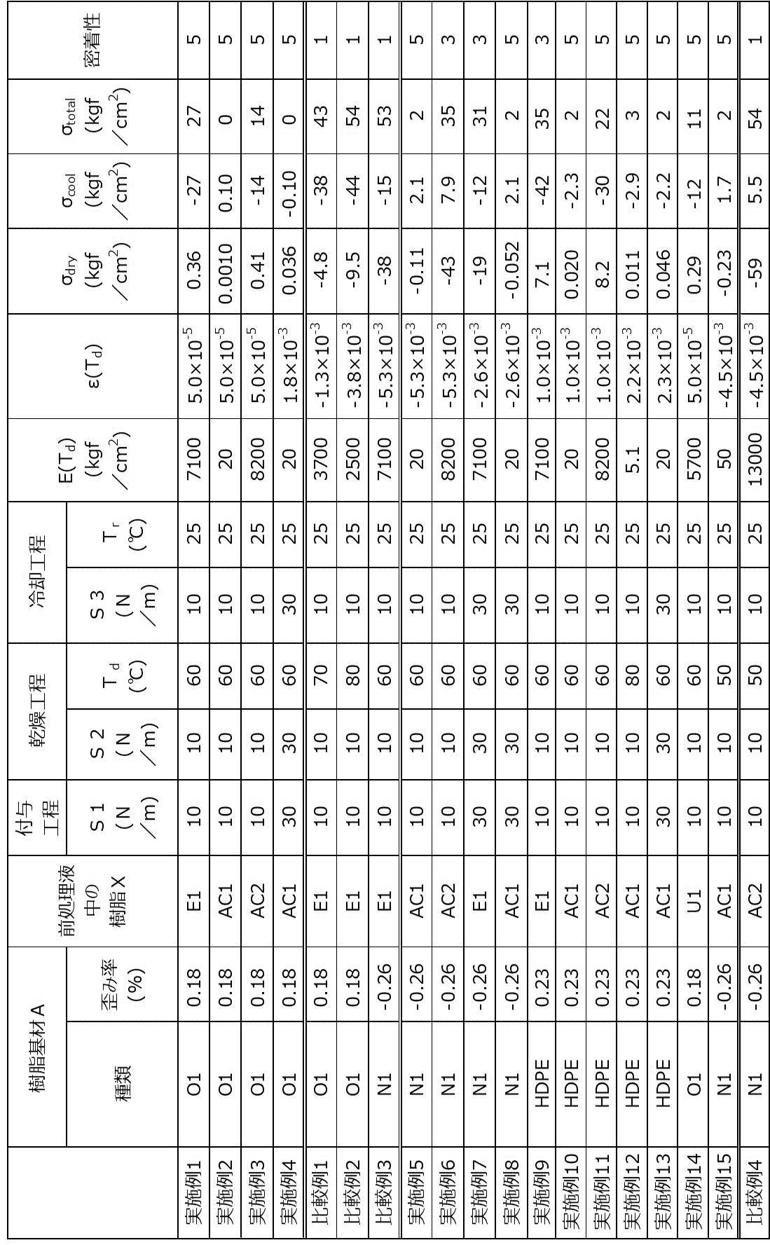
表1に示すように、σtotalが40kgf/cm2以下である実施例1~15では、σtotalが40kgf/cm2超である比較例1~4と比較して、樹脂基材Aに対する画像の密着性に優れていた。
σtotalが30kgf/cm2以下である場合には、樹脂基材Aに対する画像の密着性がより向上することが確認された。
σtotalが30kgf/cm2以下である場合には、樹脂基材Aに対する画像の密着性がより向上することが確認された。
以上、インクとして、シアンインクを用いた実施例群について説明したが、これらの実施例群において、シアンインクをシアンインク以外のインク(例えば、マゼンタインク、イエローインク、ブラックインク等)に変更した場合、又は、シアンインクに加えてシアンインク以外のインクの少なくとも1つを用いて多色の画像を記録した場合にも、上述した実施例群と同様の効果が得られることはいうまでもない。
2019年7月25日に出願された日本国特許出願2019-137000号の開示は、その全体が参照により本明細書に取り込まれる。
本明細書に記載された全ての文献、特許出願、及び技術規格は、個々の文献、特許出願、及び技術規格が参照により取り込まれることが具体的かつ個々に記された場合と同程度に、本明細書に参照により取り込まれる。
本明細書に記載された全ての文献、特許出願、及び技術規格は、個々の文献、特許出願、及び技術規格が参照により取り込まれることが具体的かつ個々に記された場合と同程度に、本明細書に参照により取り込まれる。
Claims (7)
- 30N/mの張力が印加された状態で5℃/分の昇温速度にて25℃から60℃まで加熱されて60℃で2分間保持され、次いで30N/mの張力が印加された状態のまま5℃/分の降温速度にて25℃まで冷却された場合における、下記式(a1)で表される歪み率の絶対値が0.05%以上である樹脂基材Aを準備する工程と、
水及び樹脂Xを含有する前処理液を準備する工程と、
水及び着色剤を含有するインクを準備する工程と、
10N/m以上の張力S1が印加されている前記樹脂基材A上に、前記前処理液及び前記インクをこの順に付与して画像を得る付与工程と、
前記樹脂基材Aに対して10N/m以上の張力S2が印加されている状態で、前記画像を、50℃以上の温度Tdに加熱して乾燥させる乾燥工程と、
前記樹脂基材Aに対して10N/m以上の張力S3が印加されている状態で、前記乾燥工程後の前記画像を、30℃以下の温度Trまで冷却する冷却工程と、
を含み、
下記式(1)によって算出されるσtotalが、40kgf/cm2以下である画像記録方法。
歪み率(%)=((冷却終了時点の張力印加方向の長さ-加熱開始時点の張力印加方向の長さ)/加熱開始時点の張力印加方向の長さ)×100 … 式(a1)

式(1)中、σdryは、式(2)によって算出され、σcoolは、式(3)によって算出される。
式(2)中、
E(Td)は、kgf/cm2の単位で表した、前記温度Tdにおける前記樹脂Xの弾性率であり、
ε(Td)は、張力S2が印加された状態で25℃から温度Tdまで加熱されて温度Tdで保持され、次いで張力S2が印加された状態のまま25℃まで冷却された場合における、下記式(a2)で表される前記樹脂基材Aの張力印加方向の長さの膨張率である。
樹脂基材Aの張力印加方向の長さの膨張率 = (冷却終了時点の張力印加方向の長さ-加熱開始時点の張力印加方向の長さ)/加熱開始時点の張力印加方向の長さ … 式(a2)
式(3)中、
E(T)は、kgf/cm2の単位で表した、前記冷却工程中の前記画像の温度Tにおける前記樹脂Xの弾性率であり、
αr(T)は、前記温度Tにおける前記樹脂Xの線膨張係数であり、
αs(T)は、前記温度Tにおける、前記張力S3が印加された状態の前記樹脂基材Aの張力印加方向の線膨張係数であり、
Tdは、前記温度Tdであり、
Trは、前記温度Trである。 - 前記σtotalが、30kgf/cm2以下である請求項1に記載の画像記録方法。
- 前記張力S1、前記張力S2、及び前記張力S3が、それぞれ独立に、10N/m~60N/mである請求項1又は請求項2に記載の画像記録方法。
- 前記樹脂基材Aの厚さが、12μm~60μmである請求項1~請求項3のいずれか1項に記載の画像記録方法。
- 前記樹脂基材Aが、ポリプロピレン基材又はナイロン基材である請求項1~請求項4のいずれか1項に記載の画像記録方法。
- 前記樹脂Xが、アクリル樹脂及びポリエステル樹脂の少なくとも一方である請求項1~請求項5のいずれか1項に記載の画像記録方法。
- 前記樹脂基材Aの形状が、長尺フィルム形状であり、
前記付与工程における前記前処理液及び前記インクの付与、前記乾燥工程における前記画像の乾燥、並びに、前記冷却工程における前記画像の冷却は、前記樹脂基材Aを、前記樹脂基材Aの長手方向にロール・ツー・ロール方式で搬送しながら行う請求項1~請求項6のいずれか1項に記載の画像記録方法。
Priority Applications (4)
| Application Number | Priority Date | Filing Date | Title |
|---|---|---|---|
| EP20843388.8A EP4005797A4 (en) | 2019-07-25 | 2020-07-13 | IMAGE RECORDING PROCEDURE |
| CN202080053310.3A CN114174071B (zh) | 2019-07-25 | 2020-07-13 | 图像记录方法 |
| JP2021533961A JP7133716B2 (ja) | 2019-07-25 | 2020-07-13 | 画像記録方法 |
| US17/582,222 US20220143998A1 (en) | 2019-07-25 | 2022-01-24 | Image recording method |
Applications Claiming Priority (2)
| Application Number | Priority Date | Filing Date | Title |
|---|---|---|---|
| JP2019-137000 | 2019-07-25 | ||
| JP2019137000 | 2019-07-25 |
Related Child Applications (1)
| Application Number | Title | Priority Date | Filing Date |
|---|---|---|---|
| US17/582,222 Continuation US20220143998A1 (en) | 2019-07-25 | 2022-01-24 | Image recording method |
Publications (1)
| Publication Number | Publication Date |
|---|---|
| WO2021015046A1 true WO2021015046A1 (ja) | 2021-01-28 |
Family
ID=74193458
Family Applications (1)
| Application Number | Title | Priority Date | Filing Date |
|---|---|---|---|
| PCT/JP2020/027293 WO2021015046A1 (ja) | 2019-07-25 | 2020-07-13 | 画像記録方法 |
Country Status (5)
| Country | Link |
|---|---|
| US (1) | US20220143998A1 (ja) |
| EP (1) | EP4005797A4 (ja) |
| JP (1) | JP7133716B2 (ja) |
| CN (1) | CN114174071B (ja) |
| WO (1) | WO2021015046A1 (ja) |
Cited By (1)
| Publication number | Priority date | Publication date | Assignee | Title |
|---|---|---|---|---|
| WO2023176296A1 (ja) * | 2022-03-14 | 2023-09-21 | 富士フイルム株式会社 | インクジェット記録方法 |
Families Citing this family (1)
| Publication number | Priority date | Publication date | Assignee | Title |
|---|---|---|---|---|
| EP3888924A1 (en) * | 2020-04-01 | 2021-10-06 | Canon Production Printing Holding B.V. | Wet on wet inkjet printing method |
Citations (18)
| Publication number | Priority date | Publication date | Assignee | Title |
|---|---|---|---|---|
| JPS5459936A (en) | 1977-10-03 | 1979-05-15 | Canon Inc | Recording method and device therefor |
| JPS59157636A (ja) | 1983-02-25 | 1984-09-07 | Fuji Photo Film Co Ltd | カラ−画像形成方法 |
| JP2003306623A (ja) | 2002-04-16 | 2003-10-31 | Fuji Photo Film Co Ltd | 水性インク |
| JP2003322926A (ja) | 2002-05-02 | 2003-11-14 | Fuji Photo Film Co Ltd | ハロゲン化銀写真感光材料 |
| JP2004309806A (ja) | 2003-04-08 | 2004-11-04 | Fuji Photo Film Co Ltd | ハロゲン化銀写真感光材料 |
| JP2004325707A (ja) | 2003-04-24 | 2004-11-18 | Fuji Photo Film Co Ltd | ハロゲン化銀写真感光材料および水性塗布組成物 |
| JP2009241586A (ja) | 2008-03-12 | 2009-10-22 | Fujifilm Corp | 画像記録方法、インクセット、及びインクジェット記録物 |
| JP2011042150A (ja) | 2009-08-24 | 2011-03-03 | Fujifilm Corp | 画像形成方法 |
| JP2013001854A (ja) | 2011-06-17 | 2013-01-07 | Fujifilm Corp | インクセット及び画像形成方法 |
| JP2016145312A (ja) | 2015-01-29 | 2016-08-12 | 富士フイルム株式会社 | インクセット及び画像形成方法 |
| JP2016188345A (ja) | 2015-03-30 | 2016-11-04 | 富士フイルム株式会社 | インクジェット用顔料分散体及びその製造方法、インクセット、並びに画像形成方法 |
| WO2017069074A1 (ja) * | 2015-10-19 | 2017-04-27 | コニカミノルタ株式会社 | 記録方法、乾燥方法、記録システムおよび乾燥装置 |
| JP2017088646A (ja) | 2015-11-02 | 2017-05-25 | サカタインクス株式会社 | インクジェット記録用プライマーインクおよびインクジェット記録用インクセット |
| WO2017138436A1 (ja) * | 2016-02-12 | 2017-08-17 | 花王株式会社 | インクジェット記録装置 |
| JP2018187829A (ja) * | 2017-05-02 | 2018-11-29 | キヤノン株式会社 | インクジェット記録方法 |
| WO2019004485A1 (ja) * | 2017-06-30 | 2019-01-03 | 富士フイルム株式会社 | 非浸透媒体印刷用前処理液、印刷用基材、印刷用基材の製造方法、画像記録方法及びインクセット |
| WO2019064978A1 (ja) * | 2017-09-29 | 2019-04-04 | 富士フイルム株式会社 | 画像形成方法及びインクセット |
| JP2019137000A (ja) | 2018-02-14 | 2019-08-22 | ユーエムジー・エービーエス株式会社 | 被覆成形体 |
Family Cites Families (5)
| Publication number | Priority date | Publication date | Assignee | Title |
|---|---|---|---|---|
| CN102295860A (zh) * | 2005-03-31 | 2011-12-28 | 精工爱普生株式会社 | 塑料膜用的处理液、印刷底层液、墨液组合物和使用了这些的喷墨记录方法 |
| JP6530509B2 (ja) * | 2015-12-07 | 2019-06-12 | 富士フイルム株式会社 | 透明樹脂基材印画物の製造方法 |
| EP3578377B1 (en) * | 2017-01-31 | 2021-05-05 | FUJIFILM Corporation | Inkjet recording method and manufacturing method of laminate printed article |
| JP6922292B2 (ja) * | 2017-03-17 | 2021-08-18 | セイコーエプソン株式会社 | インクジェット記録方法 |
| JP6977500B2 (ja) * | 2017-11-20 | 2021-12-08 | 東洋インキScホールディングス株式会社 | 水性記録液セット、およびそれらを用いた印刷物の製造方法 |
-
2020
- 2020-07-13 EP EP20843388.8A patent/EP4005797A4/en active Pending
- 2020-07-13 WO PCT/JP2020/027293 patent/WO2021015046A1/ja active Application Filing
- 2020-07-13 CN CN202080053310.3A patent/CN114174071B/zh active Active
- 2020-07-13 JP JP2021533961A patent/JP7133716B2/ja active Active
-
2022
- 2022-01-24 US US17/582,222 patent/US20220143998A1/en active Pending
Patent Citations (18)
| Publication number | Priority date | Publication date | Assignee | Title |
|---|---|---|---|---|
| JPS5459936A (en) | 1977-10-03 | 1979-05-15 | Canon Inc | Recording method and device therefor |
| JPS59157636A (ja) | 1983-02-25 | 1984-09-07 | Fuji Photo Film Co Ltd | カラ−画像形成方法 |
| JP2003306623A (ja) | 2002-04-16 | 2003-10-31 | Fuji Photo Film Co Ltd | 水性インク |
| JP2003322926A (ja) | 2002-05-02 | 2003-11-14 | Fuji Photo Film Co Ltd | ハロゲン化銀写真感光材料 |
| JP2004309806A (ja) | 2003-04-08 | 2004-11-04 | Fuji Photo Film Co Ltd | ハロゲン化銀写真感光材料 |
| JP2004325707A (ja) | 2003-04-24 | 2004-11-18 | Fuji Photo Film Co Ltd | ハロゲン化銀写真感光材料および水性塗布組成物 |
| JP2009241586A (ja) | 2008-03-12 | 2009-10-22 | Fujifilm Corp | 画像記録方法、インクセット、及びインクジェット記録物 |
| JP2011042150A (ja) | 2009-08-24 | 2011-03-03 | Fujifilm Corp | 画像形成方法 |
| JP2013001854A (ja) | 2011-06-17 | 2013-01-07 | Fujifilm Corp | インクセット及び画像形成方法 |
| JP2016145312A (ja) | 2015-01-29 | 2016-08-12 | 富士フイルム株式会社 | インクセット及び画像形成方法 |
| JP2016188345A (ja) | 2015-03-30 | 2016-11-04 | 富士フイルム株式会社 | インクジェット用顔料分散体及びその製造方法、インクセット、並びに画像形成方法 |
| WO2017069074A1 (ja) * | 2015-10-19 | 2017-04-27 | コニカミノルタ株式会社 | 記録方法、乾燥方法、記録システムおよび乾燥装置 |
| JP2017088646A (ja) | 2015-11-02 | 2017-05-25 | サカタインクス株式会社 | インクジェット記録用プライマーインクおよびインクジェット記録用インクセット |
| WO2017138436A1 (ja) * | 2016-02-12 | 2017-08-17 | 花王株式会社 | インクジェット記録装置 |
| JP2018187829A (ja) * | 2017-05-02 | 2018-11-29 | キヤノン株式会社 | インクジェット記録方法 |
| WO2019004485A1 (ja) * | 2017-06-30 | 2019-01-03 | 富士フイルム株式会社 | 非浸透媒体印刷用前処理液、印刷用基材、印刷用基材の製造方法、画像記録方法及びインクセット |
| WO2019064978A1 (ja) * | 2017-09-29 | 2019-04-04 | 富士フイルム株式会社 | 画像形成方法及びインクセット |
| JP2019137000A (ja) | 2018-02-14 | 2019-08-22 | ユーエムジー・エービーエス株式会社 | 被覆成形体 |
Cited By (1)
| Publication number | Priority date | Publication date | Assignee | Title |
|---|---|---|---|---|
| WO2023176296A1 (ja) * | 2022-03-14 | 2023-09-21 | 富士フイルム株式会社 | インクジェット記録方法 |
Also Published As
| Publication number | Publication date |
|---|---|
| US20220143998A1 (en) | 2022-05-12 |
| JPWO2021015046A1 (ja) | 2021-01-28 |
| CN114174071B (zh) | 2022-10-28 |
| CN114174071A (zh) | 2022-03-11 |
| EP4005797A1 (en) | 2022-06-01 |
| JP7133716B2 (ja) | 2022-09-08 |
| EP4005797A4 (en) | 2022-11-23 |
Similar Documents
| Publication | Publication Date | Title |
|---|---|---|
| US11939483B2 (en) | Ink set, image recording method, method of producing laminate, image recorded material, and laminate | |
| JP6997201B2 (ja) | 画像形成方法及びインクセット | |
| US20220143998A1 (en) | Image recording method | |
| WO2020195360A1 (ja) | 非浸透性基材用インクジェットインク、画像記録方法、及びラミネート体の製造方法 | |
| JPWO2020049929A1 (ja) | 非浸透性基材印刷用インク組成物及び画像記録方法 | |
| US11807024B2 (en) | Image recording method | |
| JP6964760B2 (ja) | インクジェットインク組成物、画像記録方法、及び、画像記録物 | |
| WO2020195211A1 (ja) | インクセット、画像記録方法、及び、画像記録物 | |
| WO2019150878A1 (ja) | 被記録媒体の製造方法、及び、画像記録方法 | |
| WO2020066454A1 (ja) | 前処理液、インクセット、画像記録用基材、画像記録用基材の製造方法、画像記録物、及び画像記録方法 | |
| US11338592B2 (en) | Image recording method and image recording system | |
| WO2021140772A1 (ja) | 画像記録方法 | |
| US20220227154A1 (en) | Image recorded material and method of producing same, and laminate and method of producing same | |
| WO2021131496A1 (ja) | 画像記録方法 | |
| JP7371265B2 (ja) | 非浸透性基材用前処理液及びインクセット | |
| WO2020235296A1 (ja) | 非浸透性基材用前処理液、インクセット、画像記録方法、画像記録物、並びに、被記録媒体及びその製造方法 | |
| WO2024062915A1 (ja) | 画像記録方法及び画像記録装置 | |
| JP7354413B2 (ja) | 非浸透性基材用前処理液、及び画像記録方法 | |
| WO2024024526A1 (ja) | 画像記録方法及び画像記録装置 |
Legal Events
| Date | Code | Title | Description |
|---|---|---|---|
| 121 | Ep: the epo has been informed by wipo that ep was designated in this application |
Ref document number: 20843388 Country of ref document: EP Kind code of ref document: A1 |
|
| ENP | Entry into the national phase |
Ref document number: 2021533961 Country of ref document: JP Kind code of ref document: A |
|
| NENP | Non-entry into the national phase |
Ref country code: DE |
|
| WWE | Wipo information: entry into national phase |
Ref document number: 2020843388 Country of ref document: EP |