WO2021010240A1 - ソレノイド - Google Patents
ソレノイド Download PDFInfo
- Publication number
- WO2021010240A1 WO2021010240A1 PCT/JP2020/026647 JP2020026647W WO2021010240A1 WO 2021010240 A1 WO2021010240 A1 WO 2021010240A1 JP 2020026647 W JP2020026647 W JP 2020026647W WO 2021010240 A1 WO2021010240 A1 WO 2021010240A1
- Authority
- WO
- WIPO (PCT)
- Prior art keywords
- core
- solenoid
- magnetic flux
- plunger
- magnetic
- Prior art date
- Legal status (The legal status is an assumption and is not a legal conclusion. Google has not performed a legal analysis and makes no representation as to the accuracy of the status listed.)
- Ceased
Links
Images

Classifications
-
- H—ELECTRICITY
- H01—ELECTRIC ELEMENTS
- H01F—MAGNETS; INDUCTANCES; TRANSFORMERS; SELECTION OF MATERIALS FOR THEIR MAGNETIC PROPERTIES
- H01F7/00—Magnets
- H01F7/06—Electromagnets; Actuators including electromagnets
- H01F7/08—Electromagnets; Actuators including electromagnets with armatures
- H01F7/16—Rectilinearly-movable armatures
- H01F7/1607—Armatures entering the winding
-
- F—MECHANICAL ENGINEERING; LIGHTING; HEATING; WEAPONS; BLASTING
- F16—ENGINEERING ELEMENTS AND UNITS; GENERAL MEASURES FOR PRODUCING AND MAINTAINING EFFECTIVE FUNCTIONING OF MACHINES OR INSTALLATIONS; THERMAL INSULATION IN GENERAL
- F16K—VALVES; TAPS; COCKS; ACTUATING-FLOATS; DEVICES FOR VENTING OR AERATING
- F16K31/00—Actuating devices; Operating means; Releasing devices
- F16K31/02—Actuating devices; Operating means; Releasing devices electric; magnetic
- F16K31/06—Actuating devices; Operating means; Releasing devices electric; magnetic using a magnet, e.g. diaphragm valves, cutting off by means of a liquid
- F16K31/0603—Multiple-way valves
- F16K31/061—Sliding valves
- F16K31/0613—Sliding valves with cylindrical slides
-
- F—MECHANICAL ENGINEERING; LIGHTING; HEATING; WEAPONS; BLASTING
- F16—ENGINEERING ELEMENTS AND UNITS; GENERAL MEASURES FOR PRODUCING AND MAINTAINING EFFECTIVE FUNCTIONING OF MACHINES OR INSTALLATIONS; THERMAL INSULATION IN GENERAL
- F16K—VALVES; TAPS; COCKS; ACTUATING-FLOATS; DEVICES FOR VENTING OR AERATING
- F16K31/00—Actuating devices; Operating means; Releasing devices
- F16K31/02—Actuating devices; Operating means; Releasing devices electric; magnetic
- F16K31/06—Actuating devices; Operating means; Releasing devices electric; magnetic using a magnet, e.g. diaphragm valves, cutting off by means of a liquid
- F16K31/0675—Electromagnet aspects, e.g. electric supply therefor
-
- H—ELECTRICITY
- H01—ELECTRIC ELEMENTS
- H01F—MAGNETS; INDUCTANCES; TRANSFORMERS; SELECTION OF MATERIALS FOR THEIR MAGNETIC PROPERTIES
- H01F7/00—Magnets
- H01F7/06—Electromagnets; Actuators including electromagnets
- H01F7/08—Electromagnets; Actuators including electromagnets with armatures
- H01F7/081—Magnetic constructions
- H01F2007/085—Yoke or polar piece between coil bobbin and armature having a gap, e.g. filled with nonmagnetic material
-
- H—ELECTRICITY
- H01—ELECTRIC ELEMENTS
- H01F—MAGNETS; INDUCTANCES; TRANSFORMERS; SELECTION OF MATERIALS FOR THEIR MAGNETIC PROPERTIES
- H01F7/00—Magnets
- H01F7/06—Electromagnets; Actuators including electromagnets
- H01F7/08—Electromagnets; Actuators including electromagnets with armatures
- H01F7/081—Magnetic constructions
- H01F2007/086—Structural details of the armature
Definitions
- This disclosure relates to solenoids.
- a solenoid has a coil portion that generates magnetic flux when energized, a side surface portion along the axial direction, and a bottom portion formed along a direction intersecting the axial direction, and a yoke that accommodates the coil portion.
- a columnar plunger that slides in the axial direction and a stator core that are arranged so as to face the tip surface of the plunger in the axial direction and magnetically attract the plunger by the magnetic flux generated by the coil portion.
- a sliding core having a first magnetic flux transfer portion formed from the end portions of the opposing cores toward the outside in the radial direction and transferring magnetic flux between the yoke and the core portion, and the sliding core.
- a stator core having a magnetic flux passage suppressing portion that suppresses the passage of magnetic flux between the magnetic flux core and the magnetic attraction core, and a side opposite to the axial end portion of the magnetic attraction core that faces the tip surface.
- the first magnetic flux delivery portion is provided with a second magnetic flux delivery portion that is arranged outside the end portion of the magnetic attraction core on the side in the radial direction and that transfers magnetic flux between the magnetic attraction core and the side surface portion.
- At least one of the first facing surface facing the bottom portion and the second facing surface facing the first magnetic flux delivery portion at the bottom portion is inside the first magnetic flux delivery portion in the radial direction.
- a breathing groove that communicates with the outside is formed so as to be in the vertical direction when the solenoid is assembled.
- the sliding core is formed with a tubular core portion arranged radially outside the plunger and from the core end portion of the core portion toward the outside in the radial direction to transfer magnetic flux. Since it has a first magnetic flux delivery portion for performing the above, there is almost no radial gap between the core portion and the first magnetic flux delivery portion. Therefore, it is possible to prevent the core portion and the first magnetic flux delivery portion from being eccentric, so that the distribution of the magnetic flux transmitted from the first magnetic flux delivery portion to the plunger via the core portion due to such eccentricity is in the radial direction. It is possible to suppress the occurrence of bias. Therefore, it is possible to suppress an increase in side force due to a bias in the distribution of magnetic flux.
- the diameter of the first magnetic flux delivery portion is formed on at least one of the first facing surface facing the bottom of the yoke in the first magnetic flux delivery portion and the second facing surface facing the first magnetic flux delivery portion in the bottom portion.
- a breathing groove that communicates the inside and outside of the direction is formed so as to be in the top direction when the solenoid is assembled. Therefore, the foreign matter flowing from the outside of the solenoid to the inside of the solenoid passes through a relatively long path in order to reach the breathing groove. For example, if the inflow portion that allows the fluid existing in the solenoid mounting environment to flow into the inside of the solenoid is formed so as to be in a direction different from the top direction when the solenoid is assembled, the direction is the top direction.
- This disclosure can also be realized in various forms.
- it can be realized in the form of a solenoid valve, a method for manufacturing a solenoid, or the like.
- FIG. 1 is a cross-sectional view showing a schematic configuration of a linear solenoid valve to which the solenoid of the first embodiment is applied.
- FIG. 2 is a cross-sectional view showing a detailed configuration of the solenoid.
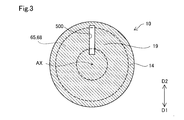
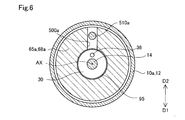
- FIG. 3 is a cross-sectional view taken along the line III-III of FIG.
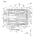
- FIG. 4 is a cross-sectional view showing a detailed configuration of the solenoid of the second embodiment.
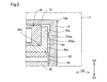
- FIG. 5 is an enlarged cross-sectional view showing the region V of FIG. 4 in an enlarged manner.
- FIG. 6 is a cross-sectional view taken along the line VI-VI of FIG.
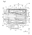
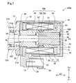
- FIG. 7 is a cross-sectional view showing a detailed configuration of the solenoid of the third embodiment.
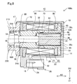
- FIG. 8 is a cross-sectional view showing a detailed configuration of the solenoid of the fourth embodiment.
- FIG. 1 schematically shows a cross section of the linear solenoid valve 300 cut along the central axis AX.
- the linear solenoid valve 300 includes a spool valve 200 and a solenoid 100 arranged side by side along the central axis AX. Note that FIGS. 1 and 2 show the solenoid 100 and the linear solenoid valve 300 in the non-energized state.
- the linear solenoid valve 300 of the present embodiment is a normally closed type, but may be a normally open type.
- the spool valve 200 shown in FIG. 1 adjusts the opening areas of a plurality of oil ports 214, which will be described later.
- the spool valve 200 includes a sleeve 210, a spool 220, a spring 230, and a spring load adjusting unit 240.
- the sleeve 210 has a substantially cylindrical external shape.
- the sleeve 210 is formed with an insertion hole 212 penetrating along the central axis AX and a plurality of oil ports 214 communicating with the insertion hole 212 and opening in the radial direction.
- a spool 220 is inserted into the insertion hole 212.
- the end of the insertion hole 212 on the solenoid 100 side is formed with an enlarged diameter and functions as an elastic member accommodating portion 218.
- the elastic member 420 which will be described later, is accommodated in the elastic member accommodating portion 218.
- the plurality of oil ports 214 are formed side by side along a direction parallel to the central axis AX (hereinafter, also referred to as "axial direction AD").
- the plurality of oil ports 214 are, for example, an input port that communicates with an oil pump (not shown) to receive an oil supply, an output port that communicates with a clutch piston (not shown), etc. It functions as a feedback port that applies a load to the vehicle, a drain port that discharges hydraulic oil, and so on.
- a collar portion 216 is formed at the end of the sleeve 210 on the solenoid 100 side.
- the flange portion 216 has a diameter increasing outward in the radial direction, and is fixed to each other with the yoke 10 of the solenoid 100 described later.
- the radial direction means a direction orthogonal to the axial direction AD.
- the spool 220 has a substantially rod-like external shape in which a plurality of large-diameter portions 222 and small-diameter portions 224 are arranged side by side along the axial direction AD.
- the spool 220 slides along the axial direction AD inside the insertion hole 212, and opens a plurality of oil ports 214 according to the positions of the large diameter portion 222 and the small diameter portion 224 along the axial direction AD. adjust.
- a shaft 90 for transmitting the thrust of the solenoid 100 to the spool 220 is in contact with the end of the spool 220 on the solenoid 100 side.
- a spring 230 is arranged at the other end of the spool 220.
- the spring 230 is composed of a compression coil spring, and presses the spool 220 in the axial direction AD to urge the spool 220 toward the solenoid 100.
- the spring load adjusting unit 240 is arranged in contact with the spring 230, and the amount of screwing into the sleeve 210 is adjusted to adjust the spring load of the spring 230.
- the solenoid 100 shown in FIGS. 1 and 2 is energized and controlled by an electronic control device (not shown) to drive the spool valve 200.
- the solenoid 100 includes a yoke 10, a coil portion 20, a plunger 30, a stator core 40, a ring member 80, and an elastic member 420.
- the yoke 10 is formed of a magnetic metal and constitutes the outer shell of the solenoid 100.
- the yoke 10 has a bottomed tubular appearance shape, and accommodates the coil portion 20, the plunger 30, and the stator core 40.
- the yoke 10 has a side surface portion 12, a bottom portion 14, an opening portion 17, and a notch portion 18.
- the side surface portion 12 has a substantially cylindrical appearance shape along the axial direction AD, and is arranged outside the coil portion 20 in the radial direction.
- the bottom portion 14 is connected to the end portion of the side surface portion 12 opposite to the spool valve 200 side and is formed perpendicular to the axial direction AD, and closes the end portion of the side surface portion 12.
- the bottom portion 14 is not limited to being perpendicular to the axial direction AD, but may be formed substantially perpendicular to the axial direction AD, or may be formed so as to intersect the axial direction AD according to the shape of the magnetic flux delivery portion 65 described later.
- the bottom portion 14 faces the proximal end surface 34 of the plunger 30, which will be described later. A detailed description of the bottom 14 will be given later.
- the space surrounded by the bottom portion 14, the stator core 40, and the shaft 90 is also referred to as a “plunger chamber 95”.
- the plunger 30 is housed in the plunger room 95.
- the opening 17 is formed at the end of the side surface 12 on the spool valve 200 side.
- the opening 17 is caulked and fixed to the flange portion 216 of the spool valve 200 after the components of the solenoid 100 are assembled inside the yoke 10.
- the spool valve 200 and the yoke 10 may be fixed by any method such as welding.
- the notch 18 is formed by notching a part of the opening 17 in the circumferential direction.
- the notch 18 of the present embodiment is formed so as to be in the ground direction D1 in the circumferential direction in a state where the solenoid 100 is assembled (hereinafter, also referred to as an “assembled state”). More specifically, it is formed so as to be in the vertical downward direction, but it is not limited to the vertical downward direction, but is less than 90 ° with respect to the vertical downward direction, such as an angle rotated by 45 ° with respect to the vertical downward direction. It may be formed at a position rotated by an angle.
- the notch 18 exposes the connector 26, which will be described later, from the yoke 10.
- the notch portion 18 functions as an inflow portion for flowing a fluid existing in the mounting environment of the solenoid 100 from the outside of the solenoid 100 into the inside of the solenoid 100.
- the fluid existing in the mounting environment of the solenoid 100 corresponds to a fluid such as hydraulic oil or air.
- the fluid that has flowed into the solenoid 100 through the notch 18 flows out to the outside of the solenoid 100 through the notch 18.
- the coil portion 20 is arranged inside the side surface portion 12 of the yoke 10 in the radial direction.
- the coil portion 20 generates a magnetic force when energized, and a loop-shaped magnetic flux flows through the side surface portion 12 of the yoke 10, the bottom portion 14 of the yoke 10, the stator core 40, the plunger 30, and the ring member 80. (Hereinafter, also referred to as "magnetic circuit") is formed.
- the coil portion 20 is not energized and the magnetic circuit is not formed. However, for convenience of explanation, the magnetic circuit formed when the coil portion 20 is energized is executed.
- a part of C1 is schematically shown by a thick arrow in FIG.
- the coil portion 20 has a coil 21 and a bobbin 22.
- the coil 21 is formed of a conducting wire having an insulating coating.
- the bobbin 22 is made of resin, and the coil 21 is wound around it.
- the bobbin 22 is connected to a connector 26 arranged on the outer peripheral portion of the yoke 10.
- the connector 26 is exposed from the yoke 10 via the notch 18.
- a connection terminal 24 to which the end of the coil 21 is connected is arranged inside the connector 26, .
- the connector 26 electrically connects the solenoid 100 and the electronic control device via a connection line (not shown).
- the outer diameter of the coil portion 20 is formed to be smaller than the inner diameter of the side surface portion 12 of the yoke 10. With such a configuration, a radial gap is formed over the entire circumference between the inner surface of the side surface portion 12 and the outer surface of the coil portion 20, and the radial outside of the magnetic flux delivery portion 65, which will be described later. It functions as a respiratory passage 28 that communicates with the outside of the solenoid 100.
- the breathing path 28 communicates with the outside of the solenoid 100 through the notch 18 of the yoke 10 to circulate the fluid existing in the mounting environment of the solenoid 100.
- the notch 18 when the notch 18 is immersed in the hydraulic oil, the hydraulic oil as a fluid is circulated, and the notch 18 is located vertically above the storage level of the hydraulic oil. Circulates air as a fluid.
- the plunger 30 is housed in the plunger room 95.
- the plunger 30 has a substantially columnar appearance shape and is made of a magnetic metal.
- the plunger 30 slides on the inner peripheral surface of the core portion 61 of the stator core 40, which will be described later, in the axial direction AD.
- the shaft 90 described above is in contact with the end surface (hereinafter, also referred to as “tip surface 32”) of the plunger 30 on the spool valve 200 side.
- tip surface 32 the end surface of the plunger 30 on the spool valve 200 side.
- the end surface of the plunger 30 opposite to the front end surface 32 faces the bottom portion 14 of the yoke 10.
- the plunger 30 is formed with a breathing hole 36 penetrating in the axial direction AD.
- the breathing hole 36 allows fluids located on the proximal end surface 34 side and the distal end surface 32 side of the plunger 30 to flow in the plunger chamber 95.
- the stator core 40 is made of a magnetic metal and is arranged between the coil portion 20 and the plunger 30.
- the stator core 40 is composed of a member in which a magnetic attraction core 50, a sliding core 60, and a magnetic flux passage suppressing portion 70 are integrated.
- the magnetic attraction core 50 is arranged so as to surround the shaft 90 in the circumferential direction.
- the magnetic attraction core 50 constitutes a portion of the stator core 40 on the spool valve 200 side, and magnetically attracts the plunger 30 by the magnetic force generated by the coil portion 20.
- a stopper 52 is arranged on the surface of the magnetic attraction core 50 facing the tip surface 32 of the plunger 30.
- the stopper 52 is made of a non-magnetic material and suppresses the direct contact between the plunger 30 and the magnetic attraction core 50, and prevents the plunger 30 from being separated from the magnetic attraction core 50 by magnetic attraction.
- the sliding core 60 constitutes a portion of the stator core 40 on the bottom 14 side, and is arranged on the outer side in the radial direction of the plunger 30.
- the sliding core 60 has a core portion 61 and a magnetic flux delivery portion 65.
- the core portion 61 and the magnetic flux transfer portion 65 are integrally molded.
- the core portion 61 has a substantially cylindrical appearance shape, and is arranged between the coil portion 20 and the plunger 30 in the radial direction.
- the core portion 61 guides the movement of the plunger 30 along the axial AD.
- the plunger 30 slides directly on the inner peripheral surface of the core portion 61.
- the end of the sliding core 60 which is opposite to the magnetic attraction core 50 side (hereinafter, also referred to as “core end 62”), faces the bottom 14 and is in contact with the bottom 14.
- the magnetic flux delivery portion 65 is formed from the core end portion 62 toward the outer side in the radial direction over the entire circumference of the core end portion 62. Therefore, the magnetic flux delivery portion 65 is located between the bobbin 22 and the bottom portion 14 of the yoke 10 in the axial direction AD.
- the magnetic flux transfer unit 65 transfers the magnetic flux between the yoke 10 and the plunger 30 via the core unit 61. More specifically, the magnetic flux transfer portion 65 of the present embodiment transfers the magnetic flux between the bottom portion 14 of the yoke 10 and the plunger 30.
- the magnetic flux transfer portion 65 may transfer the magnetic flux between the side surface portion 12 of the yoke 10 and the plunger 30.
- the magnetic flux delivery portion 65 of this embodiment is integrally molded with the core portion 61.
- the magnetic flux delivery portion 65 and the core portion 61 may be integrated after being formed as separate bodies from each other.
- the core portion 61 may be press-fitted into the through hole of the magnetic flux delivery portion 65 formed in a ring shape, or may be fixed by welding or the like after the core portion 61 is inserted.
- the magnetic flux delivery portion 65 is formed with a first facing surface 68 facing the bottom 14 of the yoke 10.
- the first facing surface 68 is formed in a planar shape along the radial direction.
- the portion of the bottom portion 14 facing the first facing surface 68 is also referred to as a “second facing surface 19”.
- the second facing surface 19 is formed in a planar shape along the radial direction and is in contact with the first facing surface 68.
- a breathing groove 500 is formed on the second facing surface 19.
- FIG. 3 for convenience of explanation, the position of the first facing surface 68 of the magnetic flux delivery portion 65 is shown by a broken line.
- the breathing groove 500 communicates the inside and the outside of the magnetic flux delivery portion 65 in the radial direction. Therefore, as shown in FIG. 2, the plunger chamber 95 and the outside of the solenoid 100 are communicated with each other via the breathing groove 500 and the breathing path 28. With such a configuration, the pressure fluctuation of the plunger chamber 95 is suppressed due to the sliding of the plunger 30, and the smooth sliding of the plunger 30 is suppressed.
- the breathing groove 500 of the present embodiment has a linear groove shape formed along the radial direction. Further, the breathing groove 500 of the present embodiment is formed so as to be in the vertical direction D2 in the assembled state.
- the "heavenly direction D2" is not limited to the vertically upward direction indicated by the arrow in FIG. 3, but means a direction on the vertically upward direction side rather than the horizontal direction. Therefore, the breathing groove 500 is formed in the assembled state along the direction rotated at an angle of less than 90 ° with respect to the vertically upward direction.
- the breathing groove 500 of the present embodiment is formed at a position rotated by about 180 ° in the circumferential direction with respect to the connector 26 and the notch 18.
- the fluid such as hydraulic oil existing in the mounting environment of the solenoid 100 may contain foreign matter such as abrasion powder. Such foreign matter may enter the respiratory tract 28 through the notch 18.
- the solenoid 100 of the present embodiment is formed so that the breathing groove 500 is in the vertical direction D2 in the assembled state. Therefore, the passage path from the notch 18 located in the ground direction D1 to the foreign matter flowing into the breathing path 28 to reach the breathing groove 500 located in the top direction D2 is set to be relatively long.
- the foreign matter flowing into the respiratory tract 28 from the notch 18 located in the ground direction D1 needs to go around the respiratory tract 28 in the circumferential direction by half a circumference in order to reach the respiratory groove 500 located in the heaven direction D2. There is.
- the "maze structure” means a structure that forms a path that is more complicated and has a longer path length than a linear path.
- the magnetic flux passage suppressing portion 70 shown in FIG. 2 is formed between the magnetic attraction core 50 and the core portion 61 in the axial direction AD.
- the magnetic flux passage suppressing unit 70 suppresses the flow of magnetic flux directly between the core unit 61 and the magnetic attraction core 50.
- the magnetic flux passage suppressing portion 70 of the present embodiment is configured such that the magnetic flux passage suppressing portion 70 is formed to have a thin radial thickness of the stator core 40 so that the magnetic resistance is larger than that of the magnetic attraction core 50 and the core portion 61.
- the ring member 80 is arranged between the coil portion 20 and the flange portion 216 of the spool valve 200 in the axial direction AD.
- the ring member 80 is an end portion of the magnetic attraction core 50 of the stator core 40 described later in the axial direction AD and opposite to the plunger 30 side (hereinafter, also referred to as “magnetic attraction core end portion 54”). ) Is arranged radially outside.
- the ring member 80 has a ring-shaped external shape and is made of a magnetic metal.
- the ring member 80 transfers magnetic flux between the magnetic attraction core 50 of the stator core 40 and the side surface portion 12 of the yoke 10.
- the ring member 80 is configured to be displaceable in the radial direction.
- the manufacturing dimensional variation of the stator core 40 and the axial deviation in assembly are absorbed.
- the magnetic attraction core 50 is press-fitted into the ring member 80. Not limited to press fitting, the magnetic attraction core 50 may be fitted with a slight gap in the radial direction.
- the elastic member 420 is accommodated in the elastic member accommodating portion 218 formed in the sleeve 210 of the spool valve 200, and urges the stator core 40 toward the bottom portion 14.
- the elastic member 420 is arranged in contact with the end surface of the magnetic attraction core 50 in the axial direction AD and on the side opposite to the plunger 30 side (hereinafter, also referred to as “end surface 56”).
- the elastic member 420 is composed of a compression coil spring having a substantially cylindrical appearance shape.
- a spool 220 is inserted inside the elastic member 420 in the radial direction.
- the stator core 40 is axially urged toward the bottom 14 side of the yoke 10 by the elastic member 420, the magnetic flux delivery portion 65 is pressed against the bottom 14 and from the bottom 14 of the yoke 10 to the magnetic flux delivery portion 65. The loss of the transmitted magnetic flux is suppressed.
- the yoke 10, the ring member 80, the plunger 30, and the stator core 40 are each made of iron. Not limited to iron, it may be composed of any magnetic material such as nickel and cobalt. Further, in the present embodiment, the outer peripheral surface of the plunger 30 is plated. By such a plating treatment, the surface hardness of the plunger 30 can be increased, and deterioration of slidability can be suppressed. Further, in the present embodiment, the yoke 10 is formed by press molding and the stator core 40 is formed by forging, but each may be formed by any molding method. For example, the yoke 10 may be integrated by caulking fixing, press-fitting fixing, or the like after the side surface portion 12 and the bottom portion 14 are formed separately from each other.
- FIGS. 1 and 2 show a state in which the plunger 30 is farthest from the magnetic attraction core 50 without energizing the coil 21.
- the magnetic circuit C1 is formed inside the solenoid 100.
- the plunger 30 is attracted to the magnetic attraction core 50 side by the formation of the magnetic circuit C1 and slides on the inner peripheral surface of the core portion 61 in the axial direction AD.
- the current flowing through the coil portion 20 increases, the magnetic flux density of the magnetic circuit C1 increases, and the stroke amount of the plunger 30 increases.
- the opening area of the oil port 214 is adjusted, and the oil pressure proportional to the current value flowing through the coil 21 is output.
- the core portion 61 and the magnetic flux delivery portion 65 are integrally formed. Therefore, there is no radial gap between the core portion 61 and the magnetic flux delivery portion 65, and it is possible to prevent the core portion 61 and the magnetic flux delivery portion 65 from being eccentric. Therefore, when the magnetic circuit C1 is configured by energization, it is possible to suppress the occurrence of radial bias in the distribution of the magnetic flux transmitted from the magnetic flux delivery portion 65 to the core portion 61, and from the core portion 61 to the plunger 30. It is possible to suppress the occurrence of radial bias in the distribution of the magnetic flux transmitted to.
- the magnetic flux densities of the magnetic circuit C1 can be made substantially equal in the circumferential direction. Therefore, an increase in side force due to a bias in the distribution of magnetic flux can be suppressed, and deterioration of the slidability of the plunger 30 can be suppressed.
- the magnetic flux delivery portion 65 corresponds to the first magnetic flux delivery portion in the present disclosure
- the ring member 80 corresponds to the second magnetic flux delivery portion in the present disclosure
- the notch portion 18 corresponds to the inflow portion in the present disclosure. Corresponds to.
- the sliding core 60 has a diameter from the tubular core portion 61 arranged radially outward with respect to the plunger 30 and the core end portion 62 of the core portion 61. Since the magnetic flux delivery portion 65 is formed toward the outside in the direction and transfers the magnetic flux, there is almost no radial gap between the core portion 61 and the magnetic flux delivery portion 65. Therefore, it is possible to prevent the core portion 61 and the magnetic flux delivery portion 65 from being eccentric. Therefore, the diameter of the distribution of the magnetic flux transmitted from the magnetic flux delivery portion 65 to the plunger 30 via the core portion 61 due to such eccentricity. It is possible to suppress the occurrence of directional bias. Therefore, it is possible to suppress an increase in side force due to a bias in the distribution of magnetic flux.
- a breathing groove 500 that communicates the inside and outside of the magnetic flux delivery portion 65 in the radial direction with the second facing surface 19 facing the magnetic flux delivery portion 65 at the bottom 14 of the yoke 10 becomes the top direction D2 in the assembled state. It is formed like this. Further, the notch 18 serving as the inflow port of the foreign matter flowing into the respiratory tract 28 is formed so as to be in the ground direction D1 in the assembled state. That is, the notch 18 is formed in a direction different from that of the breathing groove 500. With such a configuration, a maze structure with a long path can be realized as the structure of the respiratory path 28.
- the solenoid 100 of the first embodiment it is possible to suppress the invasion of foreign matter into the plunger chamber 95 while suppressing the increase in the side force of the solenoid 100.
- the breathing groove 500 is formed on the second facing surface 19 of the bottom portion 14 of the yoke 10, the circumferential position of the breathing groove 500 with respect to the notch 18 which is the inflow port of the foreign matter flowing into the breathing path 28 can be determined. It can be specified only by the yoke 10. Therefore, it is possible to easily realize a configuration in which the breathing groove 500 is in the vertical direction D2 in the assembled state, and it is possible to omit the step of adjusting the position of the breathing groove 500 in the circumferential direction when the solenoid 100 is assembled.
- the solenoid 100a of the second embodiment shown in FIG. 4 is different from the solenoid 100 of the first embodiment in that the yoke 10a and the stator core 40a are provided in place of the yoke 10 and the stator core 40. More specifically, in the solenoid 100 of the first embodiment, the breathing groove 500a is formed on the first facing surface 68a of the magnetic flux delivery portion 65a instead of the breathing groove 500 formed on the second facing surface 19 of the yoke 10. Has been done. Since the other configurations are the same as those of the solenoid 100 of the first embodiment, the same configurations are designated by the same reference numerals, and detailed description thereof will be omitted.
- a breathing groove 500a is formed on the first facing surface 68a in the magnetic flux delivery portion 65a of the sliding core 60a included in the stator core 40a of the second embodiment.
- the breathing groove 500a has a linear groove shape formed along the radial direction.
- a protruding portion 510a that protrudes toward the first facing surface 68a in the axial direction AD is formed on the second facing surface 19a of the bottom portion 14a of the yoke 10a of the second embodiment.
- the protruding portion 510a is formed so as to be in the vertical direction D2 in the assembled state.
- the protrusion 510a is formed at a position rotated by about 180 ° in the circumferential direction with respect to the connector 26 and the notch 18 shown in FIG.
- the protrusion 510a has a diameter smaller than the width of the breathing groove 500a and engages with the breathing groove 500a formed on the first facing surface 68a. By such engagement, the circumferential positions of the stator core 40a and the breathing groove 500a with respect to the yoke 10a are determined.
- the same effect as that of the first embodiment is obtained.
- the protruding portion 510a that engages with the breathing groove 500a is formed on the second facing surface 19a, the circumferential position of the breathing groove 500a with respect to the yoke 10a can be fixed. Therefore, it is possible to omit adjusting the circumferential position of the sliding core 60a when assembling the solenoid 100a, and it is possible to easily realize a configuration in which the breathing groove 500a is in the vertical direction D2 in the assembled state.
- the solenoid 100b of the third embodiment shown in FIG. 7 is different from the solenoid 100 of the first embodiment in that it includes a stator core 40b having a magnetic flux passage suppressing portion 70b instead of the magnetic flux passing suppressing portion 70. Since the other configurations are the same as those of the solenoid 100 of the first embodiment, the same configurations are designated by the same reference numerals, and detailed description thereof will be omitted.
- the magnetic flux passage suppressing portion 70b in the solenoid 100b of the third embodiment includes a connecting portion 72b formed of a non-magnetic material.
- the connecting portion 72b physically connects the magnetic attraction core 50 and the sliding core 60, which are formed as separate bodies from each other.
- the connecting portion 72b has a wall thickness substantially equal to that of the core portion 61, and is formed by brazing or the like.
- the connecting portion 72b is formed of austenitic stainless steel, but is not limited to austenitic stainless steel, and may be formed of any non-magnetic material such as aluminum or brass.
- the magnetic flux passage suppressing portion 70b includes the connecting portion 72b formed of a non-magnetic material, the magnetic flux is directly transmitted from the core portion 61 to the magnetic attraction core 50 without passing through the plunger 30 when energized. It is possible to further suppress the passage. Further, since the connecting portion 72b is formed to have a wall thickness substantially equal to that of the core portion 61, the magnetic attraction core 50 and the core portion 61 can be more firmly connected, and the plunger 30 also slides on the connecting portion 72b. Can guide you.
- the solenoid 100c of the fourth embodiment shown in FIG. 8 is different from the solenoid 100 of the first embodiment in that the plunger 30c is provided in place of the plunger 30. Since the other configurations are the same as those of the solenoid 100 of the first embodiment, the same configurations are designated by the same reference numerals, and detailed description thereof will be omitted.
- the plating treatment of the outer peripheral surface is omitted, and the outer peripheral surface is covered with the film member 39c.
- the film member 39c is formed of a Teflon sheet (Teflon is a registered trademark) and is wound around a plunger 30c. Not limited to Teflon, it may be formed of any other non-magnetic material.
- the film member 39c of the present embodiment covers the plunger 30c on the outer peripheral surface of the plunger 30c, that is, the outer surface in the radial direction, over the entire length of the axial AD of the plunger 30c.
- the total length of the axial AD of the plunger 30c is not limited, and at least a part of the outer peripheral surface of the plunger 30c including the sliding portion of the plunger 30c may be covered.
- the same effect as that of the first embodiment is obtained.
- the film member 39c formed of a non-magnetic material and covering at least a part of the outer peripheral surface of the plunger 30c is further provided, the plating treatment of the outer peripheral surface of the plunger 30c can be omitted, and the cost required for manufacturing the plunger 30c is increased. Can be suppressed.
- breathing grooves 500 and 500a in each of the above embodiments are merely examples and can be changed in various ways.
- the breathing grooves 500 and 500a are not limited to a linear groove shape along the radial direction, and may have an arbitrary groove shape such as a curved shape or a wavy shape, and are not limited to one and have two or more. Any number of grooves may be formed side by side in the circumferential direction.
- breathing grooves 500 and 500a may be formed on both the first facing surfaces 68 and 68a of the magnetic flux delivery portions 65 and 65a and the second facing surfaces 19 and 19a of the bottoms 14 and 14a, respectively.
- the breathing grooves 500 and 500a that communicate the inner and outer sides of the first magnetic flux delivery portion in the radial direction with at least one of the first facing surfaces 68 and 68a and the second facing surfaces 19 and 19a are solenoids. It may be formed so as to be in the heaven direction D2 in a state where 100, 100a to 100c are assembled. Even with such a configuration, the same effect as that of each of the above-described embodiments can be obtained.
- the protruding portion 510a is formed on the second facing surface 19a, but the protruding portion 510a may be omitted.
- the breathing groove 500a can be directed to the top direction D2 by adjusting the circumferential position of the sliding core 60a when assembling the solenoid 100a.
- any radial through hole formed in the side surface 12 of the yokes 10 and 10a exists in the mounting environment of the solenoids 100, 100a-c. It may function as an inflow part of the fluid.
- the core portions 61 of the sliding cores 60 and 60a and the magnetic flux delivery portions 65 and 65a may be formed separately from each other. In such an embodiment, the core portion 61 may be press-fitted into the inner holes of the magnetic flux delivery portions 65, 65a formed in an annular shape.
- the elastic member 420 is not limited to the compression coil spring, and may be composed of any elastic member such as a disc spring or a leaf spring.
- the elastic member accommodating portion 218, the elastic member 420 may be formed with the coil portion 20 in the axial direction AD.
- the magnetic flux delivery portions 65 and 65a may be urged by being arranged between the magnetic flux delivery portions 65 and 65a. Even with such a configuration, the same effect as that of each of the above-described embodiments can be obtained.
- the connecting portion 72b is formed to have a wall thickness substantially equal to that of the core portion 61, but is formed to be thinner than the core portion 61 and is formed on the inner peripheral surface of the coil portion 20.
- the magnetic attraction core 50 and the sliding cores 60 and 60a may be physically connected on the side or the like. Even with such a configuration, the same effect as that of the third embodiment can be obtained.
- the sheet-shaped film member 39c is wound around the plunger 30c, but the film member 39c is formed not only by winding the sheet but also by coating the outer peripheral surface of the plunger 30c. It may have been done. Further, by coating the inner peripheral surfaces of the sliding cores 60 and 60a with a non-magnetic material, at least a part of the outer peripheral surface of the plunger 30c may be covered with the film member 39c. Even with such a configuration, the same effect as that of the fourth embodiment can be obtained.
- the solenoids 100, 100a to 100c of each of the above embodiments are assembled and used so that the positions of the connector 26 and the notch 18 in the circumferential direction are in the ground direction D1, but the solenoids are not limited to the ground direction D1. It may be assembled and used so as to be in an arbitrary direction, and the notch portion 18 may be formed in a direction different from that of the breathing grooves 500 and 500a. Even with this configuration, foreign matter that has flowed into the yokes 10 and 10a from the outside of the solenoids 100 and 100a to 100a through the notch 18 passes through a relatively long path to reach the breathing grooves 500 and 500a. , The invasion of foreign matter into the plunger chamber 95 can be suppressed.
- the position of the notch 18 in the circumferential direction may be formed in the vertical direction D2, or may be formed in the same direction as the breathing grooves 500 and 500a.
- a foreign substance contained in a fluid such as air falls vertically downward according to gravity and passes through a long path in order to reach the breathing grooves 500 and 500a located in the heavenly direction D2. Therefore, it is possible to suppress the invasion of foreign matter into the plunger chamber 95.
- the solenoids 100, 100a to 100c of each of the above embodiments are applied to the linear solenoid valve 300 for controlling the hydraulic pressure of the hydraulic oil supplied to the automatic transmission for vehicles, and function as an actuator for driving the spool valve 200.
- the present disclosure is not limited to this.
- it is not limited to being mounted on a valve body provided on the outer surface of a transmission case, and may be mounted on any hydraulic device that requires control of flood control.
- an arbitrary valve such as a poppet valve may be driven, and instead of the valve, an arbitrary driven body such as a switch may be driven.
- the present disclosure is not limited to each of the above-described embodiments, and can be realized with various configurations within a range that does not deviate from the purpose.
- the technical features in each embodiment corresponding to the technical features in the embodiments described in the column of the outline of the invention may be used to solve some or all of the above-mentioned problems, or one of the above-mentioned effects. It is possible to replace or combine as appropriate to achieve a part or all. Further, if the technical feature is not described as essential in the present specification, it can be appropriately deleted.
Landscapes
- Engineering & Computer Science (AREA)
- Physics & Mathematics (AREA)
- Electromagnetism (AREA)
- General Engineering & Computer Science (AREA)
- Power Engineering (AREA)
- Mechanical Engineering (AREA)
- Magnetically Actuated Valves (AREA)
- Electromagnets (AREA)
Priority Applications (1)
| Application Number | Priority Date | Filing Date | Title |
|---|---|---|---|
| US17/566,230 US11948737B2 (en) | 2019-07-18 | 2021-12-30 | Solenoid |
Applications Claiming Priority (2)
| Application Number | Priority Date | Filing Date | Title |
|---|---|---|---|
| JP2019-132578 | 2019-07-18 | ||
| JP2019132578A JP7183985B2 (ja) | 2019-07-18 | 2019-07-18 | ソレノイド |
Related Child Applications (1)
| Application Number | Title | Priority Date | Filing Date |
|---|---|---|---|
| US17/566,230 Continuation US11948737B2 (en) | 2019-07-18 | 2021-12-30 | Solenoid |
Publications (1)
| Publication Number | Publication Date |
|---|---|
| WO2021010240A1 true WO2021010240A1 (ja) | 2021-01-21 |
Family
ID=74210661
Family Applications (1)
| Application Number | Title | Priority Date | Filing Date |
|---|---|---|---|
| PCT/JP2020/026647 Ceased WO2021010240A1 (ja) | 2019-07-18 | 2020-07-08 | ソレノイド |
Country Status (3)
| Country | Link |
|---|---|
| US (1) | US11948737B2 (enExample) |
| JP (1) | JP7183985B2 (enExample) |
| WO (1) | WO2021010240A1 (enExample) |
Families Citing this family (1)
| Publication number | Priority date | Publication date | Assignee | Title |
|---|---|---|---|---|
| KR102680617B1 (ko) * | 2022-12-29 | 2024-07-03 | 주식회사 현대케피코 | 솔레노이드 밸브 및 이를 포함하는 수소 연료 전지 차량 |
Citations (6)
| Publication number | Priority date | Publication date | Assignee | Title |
|---|---|---|---|---|
| JP2011228568A (ja) * | 2010-04-22 | 2011-11-10 | Denso Corp | リニアソレノイド |
| JP2015135135A (ja) * | 2014-01-16 | 2015-07-27 | 株式会社不二越 | 電磁比例弁 |
| JP2016149416A (ja) * | 2015-02-10 | 2016-08-18 | 株式会社デンソー | リニアソレノイド |
| JP2017161014A (ja) * | 2016-03-10 | 2017-09-14 | 日本電産トーソク株式会社 | 電磁弁装置 |
| JP2018170470A (ja) * | 2017-03-30 | 2018-11-01 | アイシン精機株式会社 | 電磁ソレノイド |
| JP2019087599A (ja) * | 2017-11-06 | 2019-06-06 | Kyb株式会社 | ソレノイドアクチュエータ |
Family Cites Families (11)
| Publication number | Priority date | Publication date | Assignee | Title |
|---|---|---|---|---|
| KR100502307B1 (ko) | 2003-07-14 | 2005-07-20 | 위니아만도 주식회사 | 솔레노이드밸브의 소음 저감 구조 |
| JP4306519B2 (ja) * | 2003-09-29 | 2009-08-05 | アイシン・エィ・ダブリュ株式会社 | 圧力制御弁 |
| JP4569371B2 (ja) | 2005-04-28 | 2010-10-27 | 株式会社デンソー | リニアソレノイド |
| JP5077331B2 (ja) * | 2009-11-16 | 2012-11-21 | 株式会社デンソー | リニアソレノイド |
| JP4844672B2 (ja) * | 2009-12-01 | 2011-12-28 | 株式会社デンソー | リニアソレノイド |
| JP5454511B2 (ja) * | 2011-05-16 | 2014-03-26 | 株式会社デンソー | ソレノイドバルブ |
| JP2012241740A (ja) * | 2011-05-16 | 2012-12-10 | Denso Corp | ソレノイドバルブおよび油圧制御装置 |
| JP5971146B2 (ja) * | 2013-02-14 | 2016-08-17 | 株式会社デンソー | リニアソレノイド |
| JP5842840B2 (ja) * | 2013-02-14 | 2016-01-13 | 株式会社デンソー | リニアソレノイド |
| JP6164167B2 (ja) * | 2014-06-25 | 2017-07-19 | 株式会社デンソー | リニアソレノイド |
| JP7031164B2 (ja) * | 2017-08-09 | 2022-03-08 | 日本電産トーソク株式会社 | ソレノイド装置及びコントロールバルブ |
-
2019
- 2019-07-18 JP JP2019132578A patent/JP7183985B2/ja active Active
-
2020
- 2020-07-08 WO PCT/JP2020/026647 patent/WO2021010240A1/ja not_active Ceased
-
2021
- 2021-12-30 US US17/566,230 patent/US11948737B2/en active Active
Patent Citations (6)
| Publication number | Priority date | Publication date | Assignee | Title |
|---|---|---|---|---|
| JP2011228568A (ja) * | 2010-04-22 | 2011-11-10 | Denso Corp | リニアソレノイド |
| JP2015135135A (ja) * | 2014-01-16 | 2015-07-27 | 株式会社不二越 | 電磁比例弁 |
| JP2016149416A (ja) * | 2015-02-10 | 2016-08-18 | 株式会社デンソー | リニアソレノイド |
| JP2017161014A (ja) * | 2016-03-10 | 2017-09-14 | 日本電産トーソク株式会社 | 電磁弁装置 |
| JP2018170470A (ja) * | 2017-03-30 | 2018-11-01 | アイシン精機株式会社 | 電磁ソレノイド |
| JP2019087599A (ja) * | 2017-11-06 | 2019-06-06 | Kyb株式会社 | ソレノイドアクチュエータ |
Also Published As
| Publication number | Publication date |
|---|---|
| US11948737B2 (en) | 2024-04-02 |
| JP7183985B2 (ja) | 2022-12-06 |
| JP2021019035A (ja) | 2021-02-15 |
| US20220122754A1 (en) | 2022-04-21 |
Similar Documents
| Publication | Publication Date | Title |
|---|---|---|
| JP5125441B2 (ja) | リニアソレノイド装置および電磁弁 | |
| JP7006571B2 (ja) | ソレノイド | |
| JP2012204574A (ja) | リニアソレノイド | |
| US20100301978A1 (en) | Linear actuator | |
| KR20210064375A (ko) | 솔레노이드 | |
| US7584937B2 (en) | Linear solenoid with abutted portion | |
| JP2009030777A (ja) | リニアソレノイド | |
| US12046418B2 (en) | Solenoid | |
| US11948737B2 (en) | Solenoid | |
| JP4492649B2 (ja) | ブリード式バルブ装置 | |
| JP2002243057A (ja) | 電磁弁装置 | |
| KR102344692B1 (ko) | 솔레노이드 | |
| US11908620B2 (en) | Solenoid | |
| WO2020226101A1 (ja) | ソレノイドバルブ | |
| JP5291548B2 (ja) | リニアソレノイド及びそれを用いたバルブ装置 | |
| JP2003207067A (ja) | 電磁弁装置 | |
| JP7136068B2 (ja) | ソレノイドバルブ | |
| JP2022049218A (ja) | ソレノイドバルブ | |
| US20230013945A1 (en) | Solenoid valve |
Legal Events
| Date | Code | Title | Description |
|---|---|---|---|
| 121 | Ep: the epo has been informed by wipo that ep was designated in this application |
Ref document number: 20839573 Country of ref document: EP Kind code of ref document: A1 |
|
| NENP | Non-entry into the national phase |
Ref country code: DE |
|
| 122 | Ep: pct application non-entry in european phase |
Ref document number: 20839573 Country of ref document: EP Kind code of ref document: A1 |