WO2021006116A1 - ガラス基体およびその製造方法 - Google Patents
ガラス基体およびその製造方法 Download PDFInfo
- Publication number
- WO2021006116A1 WO2021006116A1 PCT/JP2020/025670 JP2020025670W WO2021006116A1 WO 2021006116 A1 WO2021006116 A1 WO 2021006116A1 JP 2020025670 W JP2020025670 W JP 2020025670W WO 2021006116 A1 WO2021006116 A1 WO 2021006116A1
- Authority
- WO
- WIPO (PCT)
- Prior art keywords
- glass substrate
- main surface
- curvature
- boundary
- radius
- Prior art date
Links
Images


Classifications
-
- B—PERFORMING OPERATIONS; TRANSPORTING
- B24—GRINDING; POLISHING
- B24B—MACHINES, DEVICES, OR PROCESSES FOR GRINDING OR POLISHING; DRESSING OR CONDITIONING OF ABRADING SURFACES; FEEDING OF GRINDING, POLISHING, OR LAPPING AGENTS
- B24B9/00—Machines or devices designed for grinding edges or bevels on work or for removing burrs; Accessories therefor
- B24B9/02—Machines or devices designed for grinding edges or bevels on work or for removing burrs; Accessories therefor characterised by a special design with respect to properties of materials specific to articles to be ground
- B24B9/06—Machines or devices designed for grinding edges or bevels on work or for removing burrs; Accessories therefor characterised by a special design with respect to properties of materials specific to articles to be ground of non-metallic inorganic material, e.g. stone, ceramics, porcelain
- B24B9/08—Machines or devices designed for grinding edges or bevels on work or for removing burrs; Accessories therefor characterised by a special design with respect to properties of materials specific to articles to be ground of non-metallic inorganic material, e.g. stone, ceramics, porcelain of glass
- B24B9/10—Machines or devices designed for grinding edges or bevels on work or for removing burrs; Accessories therefor characterised by a special design with respect to properties of materials specific to articles to be ground of non-metallic inorganic material, e.g. stone, ceramics, porcelain of glass of plate glass
-
- B—PERFORMING OPERATIONS; TRANSPORTING
- B24—GRINDING; POLISHING
- B24B—MACHINES, DEVICES, OR PROCESSES FOR GRINDING OR POLISHING; DRESSING OR CONDITIONING OF ABRADING SURFACES; FEEDING OF GRINDING, POLISHING, OR LAPPING AGENTS
- B24B9/00—Machines or devices designed for grinding edges or bevels on work or for removing burrs; Accessories therefor
-
- C—CHEMISTRY; METALLURGY
- C03—GLASS; MINERAL OR SLAG WOOL
- C03C—CHEMICAL COMPOSITION OF GLASSES, GLAZES OR VITREOUS ENAMELS; SURFACE TREATMENT OF GLASS; SURFACE TREATMENT OF FIBRES OR FILAMENTS MADE FROM GLASS, MINERALS OR SLAGS; JOINING GLASS TO GLASS OR OTHER MATERIALS
- C03C19/00—Surface treatment of glass, not in the form of fibres or filaments, by mechanical means
-
- G—PHYSICS
- G09—EDUCATION; CRYPTOGRAPHY; DISPLAY; ADVERTISING; SEALS
- G09F—DISPLAYING; ADVERTISING; SIGNS; LABELS OR NAME-PLATES; SEALS
- G09F9/00—Indicating arrangements for variable information in which the information is built-up on a support by selection or combination of individual elements
Definitions
- the present invention relates to a glass substrate and a method for producing the same.
- Vehicles such as automobiles are equipped with in-vehicle display devices such as car navigation devices.
- in-vehicle display devices such as car navigation devices.
- a glass cover member (cover glass) is used from the viewpoint of protecting the display panel (see, for example, Patent Document 1).
- the in-vehicle display device mounted on the vehicle is different from the stationary display device whose installation position does not change, and the direction and intensity of the light hitting the cover glass changes rapidly. Therefore, strong light may hit the chamfered portion of the cover glass.
- the reflected light from the chamfered portion may be perceived as dazzling. If such reflected light gets into the driver's eyes, it may interfere with driving. Therefore, in a glass substrate used as a cover glass or the like of an in-vehicle display device, it is preferable that glare due to reflected light from the chamfered portion is suppressed (hereinafter, also referred to as “excellent in chamfered portion antiglare property”).
- the present invention has been made in view of the above points, and an object of the present invention is to provide a glass substrate having excellent chamfered antiglare properties and a method for producing the same.
- the present invention provides the following [1] to [10].
- [1] The first main surface, the second main surface which is the main surface opposite to the first main surface, the end surface sandwiched between the first main surface and the second main surface, and the first A first boundary surface arranged between the main surface and the end surface and connecting to the end surface, and a second boundary surface connecting the first main surface and the first boundary surface are provided, and the second boundary surface is provided.
- interface is a curved surface which is convexly curved, the radius of curvature R 2 of the second boundary surface is 0.1mm or more 2.0mm or less, the glass substrate.
- the first boundary surface is a curved surface which is convexly curved, the radius of curvature R 1 of the first boundary surface is 0.1mm or more 1.0mm or less, the above-mentioned [1] or [2]
- the glass substrate according to. [4] above than the radius of curvature R 1 of the first boundary surface, towards the radius of curvature R 2 of the second boundary surface is large, a glass substrate according to above [3].
- a method for manufacturing a glass substrate, wherein the ground surface of the grindstone has a shape corresponding to the shapes of the first boundary surface and the second boundary surface.
- the present invention it is possible to provide a glass substrate having excellent chamfered antiglare properties and a method for producing the same.
- FIG. 1 is a cross-sectional view showing a glass substrate.
- FIG. 2 is a cross-sectional view showing an in-vehicle display device.
- FIG. 3 is a cross-sectional view showing a modified example of the glass substrate.
- FIG. 4 is a cross-sectional view showing grinding of a glass plate using a rotary grindstone.
- FIG. 5 is a graph for explaining how to obtain the radius of curvature.
- FIG. 6 is an enlarged view of FIG.
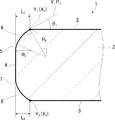
- FIG. 1 is a cross-sectional view showing a glass substrate 1.
- the glass substrate 1 is a plate-shaped glass and has a first main surface 2 and a second main surface 3 opposite to the first main surface 2.
- the first main surface 2 and the second main surface 3 are planes parallel to each other.
- the glass substrate 1 has an end surface 4 sandwiched between a first main surface 2 and a second main surface 3.
- the end surface 4 is shown as a flat surface perpendicular to the first main surface 2 and the second main surface 3.
- the end surface 4 may be a curved surface that is curved in a convex shape, as in the case of the first boundary surface 5 and the second boundary surface 6 described later.
- the glass substrate 1 has a first boundary surface 5 arranged between the first main surface 2 and the end surface 4.
- the first boundary surface 5 is connected to the end surface 4.
- the glass substrate 1 has a second boundary surface 6 arranged between the first main surface 2 and the first boundary surface 5.
- the second boundary surface 6 is connected to the first boundary surface 5 and the first main surface 2.
- the second boundary surface 6 is a curved surface that is curved in a convex shape.
- the radius of curvature R 2 of the second boundary surface 6 is 0.1 mm or more and 2.0 mm or less.
- the first boundary surface 5 and the second boundary surface 6 may be collectively referred to as a “chamfered portion”.
- the chamfered portion has excellent antiglare properties.
- FIG. 2 is a cross-sectional view showing the vehicle-mounted display device 21.
- the vehicle-mounted display device 21 shown in FIG. 2 is, as an example, a car navigation device.
- the in-vehicle display device 21 has a housing 22 for accommodating each part.
- a backlight unit 23 is housed inside the housing 22, and a display panel 24, which is a liquid crystal panel, is arranged on the backlight unit 23.
- the display panel 24 may be, for example, an organic EL panel, an electronic ink type panel, or the like, or may have a touch panel or the like.
- a glass substrate is attached to such a display panel 24 via an adhesive layer 25 so that the second main surface 3 of the glass substrate 1 is in contact with the adhesive layer 25.
- the adhesive layer 25 is, for example, OCA (Optical Clear Adhesive).
- the glass substrate 1 functions as a cover member (cover glass) that covers the display panel 24.
- the second main surface 3 of the glass substrate 1 is a surface facing the display panel 24.
- the first main surface 2 of the glass substrate 1 is a surface that does not face the display panel 24 and faces the user (for example, the driver) side of the in-vehicle display device 21.
- the vehicle-mounted display device 21 since the vehicle-mounted display device 21 is mounted on the vehicle, the direction and intensity of the light that hits the first main surface 2 of the glass substrate 1 changes rapidly. Therefore, strong light may hit the chamfered portions (first boundary surface 5 and second boundary surface 6) of the glass substrate 1, and reflected light may be emitted.
- the chamfered portion has excellent antiglare properties. It is presumed that this is because the glass substrate 1 has the above-mentioned second boundary surface 6 to reduce the amount of reflected light entering the eyes.
- the second boundary surface 6 is a curved surface that is curved in a convex shape, and the radius of curvature R 2 of the second boundary surface 6 is 0.1 mm or more and 2.0 mm or less.
- the radius of curvature R 2 of the second interface 6 is preferably at least 0.2 mm, more preferably at least 0.3 mm, more preferably not less than 0.4 mm, 0.6 mm or more Is particularly preferable.
- the radius of curvature R 2 of the second interface 6 is preferably 1.5mm or less, more preferably 1.2 mm, more preferably 1.0mm or less.
- the angle ⁇ 1 formed by the second boundary surface 6 and the first main surface 2 is preferably 10 ° or more and 45 ° or less, and more preferably 15 ° or more and 35 ° or less, because the chamfered portion is more excellent in antiglare property.
- Chipping is a chip formed on the glass surface, and the portion where such chipping is formed may have particularly strong reflected light. Therefore, the size of the chipping on the second boundary surface 6 is preferably 0.08 mm or less, more preferably 0.05 mm or less, because the chamfered portion is more excellent in antiglare property.
- the size of the chipping is measured by observing the surface of the glass substrate 1 at a magnification of 100 times using a scanning confocal laser scanning microscope (for example, OLS3000, manufactured by Olympus Corporation). Observation is performed in any five fields of view, the chipping having the longest diameter is found, and the diameter is defined as the chipping size. The diameter is the longest distance between two points in the chipping region shown in the observation field image.
- the first boundary surface 5 is preferably a curved surface that is curved in a convex shape.
- the radius of curvature R 1 of the first interface 5, for reasons of obtaining superior chamfer antiglare property is preferably at least 0.1 mm, more preferably not less than 0.3 mm.
- the radius of curvature R 1 of the first interface 5, for reasons of obtaining superior chamfer antiglare property is preferably 1.0mm or less, more preferably 0.8 mm.
- the glass substrate 1 may have a third boundary surface 7 arranged between the second main surface 3 and the end surface 4.
- the third boundary surface 7 is connected to the end surface 4.
- the glass substrate 1 may have a fourth boundary surface 8 arranged between the second main surface 3 and the third boundary surface 7.
- the fourth boundary surface 8 is connected to the second main surface 3 and the third boundary surface 7.
- the third boundary surface 7 and the fourth boundary surface 8 are curved surfaces that are curved in a convex shape, respectively.
- Curvature of the third boundary surface 7 radius may be the same as the radius of curvature R 1 of the first interface 5, may be different.
- Curvature of the fourth boundary surface 8 radii may be the same as the radius of curvature R 2 of the second interface 6, it may be different.
- the third boundary surface 7 and the fourth boundary surface 8 may both be continuous surfaces having the same radius of curvature.
- the difference from the length L 2 in the tangential direction is preferably 0.2 mm or less, and more preferably 0.1 mm or less.
- the radius of curvature R 1 and the radius of curvature R 2 , the length L 1 and the length L 2 , and the angle ⁇ 1 are, for example, 100 to 200 times using a contour measuring device (for example, a contour record manufactured by Tokyo Seimitsu Co., Ltd.). Measure at the magnification of.
- FIG. 5 is a graph for explaining how to obtain the radius of curvature, and the upper portion of FIG. 5 also shows the contour shape of the glass substrate 1.
- the contour shape of the glass substrate 1 is measured using a contour measuring device, and the radius of curvature R of the chamfered portion (first boundary surface 5 and second boundary surface 6) is calculated every 10 ⁇ m from, for example, the end surface 4 side.
- a plurality of points representing the calculated radius of curvature R are plotted. Of the calculated radius of curvature R, firstly, (in FIG.
- the radius of curvature R surrounded by broken lines S 1) a radius of curvature R of the three points worth in order from the side closer to the end surface 4 in the mean value R A ( Figure 5, (Indicated by the broken line) is calculated. Then selects a plurality of radii of curvature R to be within the scope G A to the average value R A median, a curvature radius R 1 and the average value (in FIG. 5, shown in dashed lines). Similarly, the average value of the curvature of the 3-point fraction in order from the side closer to the first major surface 2 the radius R (in FIG. 5, rate songs surrounded by broken lines S 2 radius R) R B (in FIG. 5, shown in dashed lines) Is calculated.
- Range G A and scope G B respectively, for example, in the range of ⁇ 50 [mu] m from the average value R A and the average value R B.
- 50 ⁇ m is appropriately set in consideration of processing accuracy and measurement accuracy, and may be, for example, ⁇ 100 ⁇ m, ⁇ 70 ⁇ m, ⁇ 30 ⁇ m, or the like. In this way, regardless of the distance of the first boundary surface 5 and the second boundary surface 6, also in the case where a plurality of radii of curvature R are also present, the curvature radius R 1 and radius of curvature R 2 efficiently Can be calculated.
- the length L 1 and the length L 2 are defined as follows. See FIG. Any point in the first main surface 2 and the line of intersection X 1 and the second boundary surface 6 to a point Y 1. Through the point Y 1, and the line of intersection X 1 and intersecting the vertical plane (cross section) and section Z. Sectional Z is also perpendicular plane (cross section) to the tangent line of intersection X 1 at point Y 1. In the cross section Z, from the point Y 1 to the end face 4, among the parallel distance to the first major surface 2, the longest distance is defined as the length L 1. Next, a point on the line of intersection X 2 between the second main surface 3 and the fourth boundary surface 8 and on the cross section Z is defined as a point Y 2 .
- the longest distance from the point Y 2 to the end surface 4 in the direction parallel to the second main surface 3 is defined as the length L 2 .
- the end surface 4 is a curved surface curved in a convex shape, the distance from the most protruding top of the curved surface is measured. In this case, "end face” shall be read as "top”.
- the angle ⁇ 1 will be described with reference to FIG. FIG. 6 is an enlarged view of FIG.
- the same reference numerals are used for the same parts as those described with reference to FIG. 1, and the description thereof will be omitted.
- the point P 1 is a point on the first main surface 2, and the distance between the point Y 1 and the point P 1 (distance in the direction parallel to the first main surface 2) is 50 ⁇ m.
- the straight line passing through the point Y 1 and the point P 1 is defined as the straight line Y 1 P 1 .
- the point P 2 is a point on the second boundary surface 6, and the distance between the point Y 1 and the point P 2 (distance in the direction parallel to the first main surface 2) is 50 ⁇ m.
- the straight line passing through the point Y 1 and the point P 2 is defined as a straight line Y 1 P 2 .
- the angle formed by the straight line Y 1 P 1 and the straight line Y 1 P 2 is defined as the angle ⁇ 1 .
- the glass substrate 1 is preferably a chemically strengthened glass (chemically strengthened glass).
- a compressive stress layer is formed on the surface layer of the chemically strengthened glass.
- the depth (DOL) of the compressive stress layer is preferably 10 ⁇ m or more, more preferably 15 ⁇ m or more, still more preferably 25 ⁇ m or more.
- the compressive stress value (CS) of the compressive stress layer is preferably 500 MPa or more, more preferably 650 MPa or more, and even more preferably 750 MPa or more. On the other hand, 1200 MPa or less is preferable.
- the compressive stress value (CS) of the compressive stress layer and the depth (DOL) of the compressive stress layer are determined by, for example, a surface stress meter (FSM-6000, manufactured by Orihara Seisakusho) or a scattered photoelastic stress meter (SLP-2000, Orihara). Can be measured using (manufactured by Seisakusho).
- FSM-6000 surface stress meter
- SLP-2000 scattered photoelastic stress meter
- a functional layer may be formed on the first main surface 2 and / or the second main surface 3 of the glass substrate 1.
- the functional layer include an antireflection layer, an antiglare layer (AG layer), an antifouling layer, and a light-shielding layer.
- the functional layer may be formed by treating the surface layer of the glass substrate 1, or may be formed by laminating another layer on the surface of the glass substrate 1.
- the plate thickness of the glass substrate 1 is preferably 0.5 mm or more and 2.5 mm or less, and more preferably 0.7 mm or more and 2.0 mm or less.
- the shape and size of the main surfaces (first main surface 2 and second main surface 3) of the glass substrate 1 are appropriately determined according to, for example, the shape of the vehicle-mounted display device 21 used.
- FIG. 3 is a cross-sectional view showing a modified example of the glass substrate 1.
- the glass substrate 1 is shown as a flat plate-shaped glass, but the shape of the glass substrate 1 is not limited to this.
- the glass substrate 1 may have a bent portion 12.
- the first main surface 2 is bent (curved) in a concave shape
- the other second main surface 3 is bent (curved) in a convex shape.
- the radius of curvature of the bent portion 12 is, for example, 10 mm or more and 100 mm or less.
- the first main surface 2 may be bent in a convex shape and the second main surface 3 may be bent in a concave shape.
- the use of the glass substrate 1 is not particularly limited, and for example, it is used as a cover glass of a display device, and among them, it is preferably used as a cover glass of an in-vehicle display device 21.
- the glass plate 31 is prepared.
- the glass plate 31 has a first main surface 32 which is one main surface, a second main surface 33 which is the other main surface, and an end surface 34 which connects the first main surface 32 and the second main surface 33. ..
- the first main surface 32 of the glass plate 31 becomes the first main surface 2 of the glass substrate 1.
- the second main surface 33 of the glass plate 31 becomes the second main surface 3 of the glass substrate 1.
- the plate thickness of the glass plate 31 is the same as the plate thickness of the glass substrate 1 described above.
- Examples of the glass type of the glass plate 31 include soda lime glass and aluminosilicate glass (SiO 2- Al 2 O 3- Na 2 O-based glass).
- Examples of the glass composition of the glass plate 31 include the glass composition described in paragraph [0019] of Japanese Patent Application Laid-Open No. 2019-006650.
- a chemical strengthening glass based on aluminosilicate glass is preferably used.
- FIG. 4 is a cross-sectional view showing the grinding of the glass plate 31 using the rotary grindstone 35.
- the end portion of the glass plate 31 is ground using the rotary grindstone 35.
- the glass plate 31 is chamfered.
- An annular grinding groove extending in the circumferential direction is formed on the grinding surface 36 which is the outer peripheral surface of the rotary grindstone 35.
- the ground surface 36 contains abrasive grains such as alumina, silicon carbide, and diamond.
- the particle size of the abrasive grains JIS R 6001) is not particularly limited, but is selected from, for example, a range from # 300 to # 2000.
- the rotary grindstone 35 moves relatively along the end portion of the glass plate 31 while rotating around the center line of the rotary grindstone 35, and the end portion of the glass plate 31 is ground by the grinding surface 36.
- a cooling liquid such as water may be used for grinding.
- the grinding surface 36 of the rotary grindstone 35 has at least a shape corresponding to the shape of the chamfered portion (first boundary surface 5 and second boundary surface 6) of the desired glass substrate 1 (however, , FIG. 4 is a schematic diagram, so it does not have such a shape).
- a rotary grindstone 35 is available as a custom-made product, for example.
- the above-mentioned glass substrate 1 can be obtained by grinding and chamfering the end portion of the glass plate 31 using such a rotary grindstone 35.
- the glass plate 31 In order to obtain the glass substrate 1 as shown in FIG. 3, the glass plate 31 also needs to be bent. In this case, a glass plate 31 having the same radius of curvature as the radius of curvature of the bent portion 12 of the glass substrate 1 is used. If the diameter D 1 of the rotary grindstone 35 is too large when grinding the bent glass plate 31, the corners of the rotary grindstone 35 hit the glass plate 31 on the concave side of the bent glass plate 31, and chipping is likely to be formed. In some cases. Therefore, when grinding a bent glass plate 31, it is preferable that the diameter D 1 of the rotary grindstone 35 is smaller than the radius of curvature of the glass plate 31. As a result, the formation of chipping is suppressed.
- the diameter D 1 of the rotary grindstone is preferably 5 to 30 mm in consideration of the peripheral speed of the grindstone.
- the above-mentioned glass substrate 1 may be first rough-processed with a rotary grindstone having a coarse particle size, and then finished with a rotary grindstone having a fine particle size.
- grinding may be performed using a grinding tool other than the rotary grindstone.
- a rotary grindstone is preferable.
- the glass plate 31 after grinding may be chemically strengthened.
- the glass plate 31 that has been chemically strengthened becomes the glass substrate 1.
- chemically strengthening glass is used as the glass plate 31.
- the chemical strengthening treatment a conventionally known method can be adopted, and typically, the glass plate 31 is immersed in a molten salt.
- the alkali ions Li ions and / or Na ions
- the alkaline ions Na ions and / or K ions
- the molten salt inorganic salt composition
- the molten salt preferably contains potassium nitrate (KNO 3 ).
- the treatment conditions such as the temperature of the molten salt and the immersion time may be set so that the compressive stress value (CS) of the compressive stress layer and the thickness (DOL) of the compressive stress layer become desired values.
- a functional layer may be formed on the first main surface 2 and / or the second main surface 3 of the glass substrate 1 as appropriate.
- Example 1 As the glass plate 31, AGC's "Dragon Trail" was prepared. The size of the main surfaces (first main surface 32 and second main surface 33) of the glass plate 31 was 1200 mm ⁇ 300 mm. The plate thickness of the glass plate 31 was 2.0 mm. The glass plate 31 was bent in a direction in which the first main surface 32 was concave, and the radius of curvature of the glass plate 31 was 50 mm.
- the end of the prepared glass plate 31 was ground using a custom-made rotary grindstone 35 having a specific grinding surface 36 to obtain the glass substrate 1 of Example 1.
- the diameter D 1 of the rotary grindstone 35 was 20 mm.
- the abrasive grains on the ground surface 36 of the rotary grindstone 35 were diamonds having a particle size of # 800. Grinding was done wet. That is, water was used as the cooling water during grinding.
- the glass plate 31 was chamfered by grinding the rotary grindstone 35 to form an end surface 4, a first boundary surface 5, a second boundary surface 6, a third boundary surface 7, and a fourth boundary surface 8.
- ) are shown in Table 1 below (the same applies to Examples 2 to 7 described later).
- Example 2 to 7 the glass plate 31 was ground using a rotary grindstone 35 having a different shape of the grinding surface 36 from that of Example 1 to obtain a glass substrate 1.
- a non-curved flat surface was formed as the second boundary surface 6 instead of a curved surface. Therefore, in the column of the radius of curvature R 2 of the second boundary surface 6 in Table 1, - describing the ".” Further, in Example 6, unlike Examples 1 to 5, the diameter D 1 of the rotary grindstone 35 was set to 50 mm.
- the subject was asked to record the illuminance at an angle A when the reflected light from the chamfered portion of the glass substrate 1 felt dazzling.
- the average value of the illuminance when each of the 11 subjects felt dazzling (hereinafter, simply referred to as “illuminance” in this paragraph) was calculated.
- “C” is shown when the illuminance is less than 4000 lux
- "B” is shown when the illuminance is 4000 lux or more and less than 8000 lux
- “A” is shown when the illuminance is 8000 lux or more. It can be evaluated that the larger the illuminance, the more the glare due to the reflected light from the chamfered portion of the glass substrate 1 is suppressed, and the better the chamfered portion antiglare property is.
- Examples 1 to 4 and Example 7 have excellent chamfered antiglare properties as compared with Examples 5 to 6 in which the second boundary surface 6 is a flat surface. Chamfer.
- Example 2 When comparing the examples 1 and 2, than the radius of curvature R 1 is the radius of curvature R 2 is greater than Example 2, it curvature radius R 2 is greater example 1 than the radius of curvature R 1 is chamfered portions antiglare property It was better. Comparing Example 1 and Example 7 in which only the radius of curvature R 2 is different, Example 1 having a radius of curvature R 2 of 0.6 mm has a chamfered portion than Example 7 having a radius of curvature R 2 of 0.5 mm. The anti-glare property was better.
Abstract
本発明は、面取り部防眩性に優れるガラス基体およびその製造方法を提供する。本発明のガラス基体は、第1主面と、上記第1主面とは反対側の主面である第2主面と、上記第1主面および上記第2主面に挟まれた端面と、上記第1主面と上記端面との間に配置され、上記端面に接続する第1境界面と、上記第1主面と上記第1境界面とに接続する第2境界面と、を備え、上記第2境界面が、凸状に湾曲した湾曲面であり、上記第2境界面の曲率半径R2が0.1mm以上2.0mm以下である。
Description
本発明は、ガラス基体およびその製造方法に関する。
自動車等の車両には、カーナビゲーション装置などの車載表示装置が搭載されている。
車載表示装置において、表示パネルを保護する観点から、ガラス製のカバー部材(カバーガラス)が使用されている(例えば、特許文献1参照)。
車載表示装置において、表示パネルを保護する観点から、ガラス製のカバー部材(カバーガラス)が使用されている(例えば、特許文献1参照)。
車両に搭載される車載表示装置は、設置位置が不変の据置型表示装置とは異なり、カバーガラスに当たる光の方向や強さが目まぐるしく変化する。このため、カバーガラスの面取り部に強い光が当たる場合がある。
本発明者らが検討したところ、カバーガラスとして用いるガラス基体によっては、面取り部からの反射光が眩しいと感じる場合があった。このような反射光が運転手の目に入ると、運転に支障が出る可能性がある。
したがって、車載表示装置のカバーガラス等として用いられるガラス基体においては、面取り部からの反射光による眩しさが抑制されている(以下、「面取り部防眩性に優れる」とも言う)ことが好ましい。
したがって、車載表示装置のカバーガラス等として用いられるガラス基体においては、面取り部からの反射光による眩しさが抑制されている(以下、「面取り部防眩性に優れる」とも言う)ことが好ましい。
本発明は、以上の点を鑑みてなされたものであり、面取り部防眩性に優れるガラス基体およびその製造方法を提供することを目的とする。
本発明者らは、鋭意検討した結果、下記構成を採用することにより、上記目的が達成されることを見出し、本発明を完成させた。
すなわち、本発明は、以下の[1]~[10]を提供する。
[1]第1主面と、上記第1主面とは反対側の主面である第2主面と、上記第1主面および上記第2主面に挟まれた端面と、上記第1主面と上記端面との間に配置され、上記端面に接続する第1境界面と、上記第1主面と上記第1境界面とに接続する第2境界面と、を備え、上記第2境界面が、凸状に湾曲した湾曲面であり、上記第2境界面の曲率半径R2が0.1mm以上2.0mm以下である、ガラス基体。
[2]上記第2境界面と上記第1主面とのなす角度θ1が10°以上45°以下である、上記[1]に記載のガラス基体。
[3]上記第1境界面が、凸状に湾曲した湾曲面であり、上記第1境界面の曲率半径R1が0.1mm以上1.0mm以下である、上記[1]または[2]に記載のガラス基体。
[4]上記第1境界面の曲率半径R1よりも、上記第2境界面の曲率半径R2の方が大きい、上記[3]に記載のガラス基体。
[5]上記第1主面および上記第2主面が屈曲した屈曲部を有する、上記[1]~[4]のいずれか1つに記載のガラス基体。
[6]上記第2境界面におけるチッピングのサイズが、0.08mm以下である、上記[1]~[5]のいずれか1つに記載のガラス基体。
[7]上記端面から上記第1主面までの、上記端面から上記第1主面に対して接線方向の長さL1と、上記端面から上記第2主面までの、上記端面から上記第2主面に対して接線方向の長さL2との差が、0.2mm以下である、上記[1]~[6]のいずれか1つに記載のガラス基体。
[8]表示装置のカバーガラスとして用いられる、上記[1]~[7]のいずれか1つに記載のガラス基体。
[9]上記表示装置が、車載表示装置である、上記[8]に記載のガラス基体。
[10]上記[1]~[9]のいずれか1つに記載のガラス基体を製造する方法であって、ガラス板を準備し、回転砥石を用いて、上記ガラス板を研削し、上記回転砥石の研削面は、上記第1境界面および上記第2境界面の形状に対応する形状を有する、ガラス基体の製造方法。
本発明によれば、面取り部防眩性に優れるガラス基体およびその製造方法を提供できる。
以下、本発明の好適な実施形態を、図面に基づいて説明する。
ただし、本発明は、以下の実施形態に限定されない。本発明の趣旨を逸脱することなく、以下の実施形態に種々の変形および置換を加えることができる。
ただし、本発明は、以下の実施形態に限定されない。本発明の趣旨を逸脱することなく、以下の実施形態に種々の変形および置換を加えることができる。
[ガラス基体]
図1は、ガラス基体1を示す断面図である。
ガラス基体1は、板状のガラスであって、第1主面2、および、第1主面2とは反対側の第2主面3を有する。第1主面2および第2主面3は、互いに平行な面である。
図1は、ガラス基体1を示す断面図である。
ガラス基体1は、板状のガラスであって、第1主面2、および、第1主面2とは反対側の第2主面3を有する。第1主面2および第2主面3は、互いに平行な面である。
ガラス基体1は、第1主面2と第2主面3とに挟まれた端面4を有する。
図1では、端面4を、第1主面2および第2主面3に対して垂直な平坦面として図示している。ただし、端面4は、後述する第1境界面5および第2境界面6と同様に、凸状に湾曲した湾曲面であってもよい。
図1では、端面4を、第1主面2および第2主面3に対して垂直な平坦面として図示している。ただし、端面4は、後述する第1境界面5および第2境界面6と同様に、凸状に湾曲した湾曲面であってもよい。
ガラス基体1は、第1主面2と端面4との間に配置された第1境界面5を有する。第1境界面5は、端面4に接続している。
更に、ガラス基体1は、第1主面2と第1境界面5との間に配置された第2境界面6を有する。第2境界面6は、第1境界面5と、第1主面2とに接続している。
第2境界面6は、凸状に湾曲した湾曲面である。
第2境界面6の曲率半径R2は0.1mm以上2.0mm以下である。
第2境界面6は、凸状に湾曲した湾曲面である。
第2境界面6の曲率半径R2は0.1mm以上2.0mm以下である。
以下、ガラス基体1において、第1境界面5および第2境界面6を併せて「面取り部」と呼ぶ場合がある。
このようなガラス基体1を、以下に説明するように車載表示装置のカバーガラスとして用いた場合、面取り部防眩性に優れる。
図2は、車載表示装置21を示す断面図である。
図2に示す車載表示装置21は、一例として、カーナビゲーション装置である。
車載表示装置21は、各部を収納する筐体22を有する。筐体22の内部には、バックライトユニット23が収納され、その上に、液晶パネルである表示パネル24が配置されている。表示パネル24は、例えば、有機ELパネル、電子インク型パネル等であってもよく、タッチパネル等を有していてもよい。
図2に示す車載表示装置21は、一例として、カーナビゲーション装置である。
車載表示装置21は、各部を収納する筐体22を有する。筐体22の内部には、バックライトユニット23が収納され、その上に、液晶パネルである表示パネル24が配置されている。表示パネル24は、例えば、有機ELパネル、電子インク型パネル等であってもよく、タッチパネル等を有していてもよい。
このような表示パネル24には、粘着層25を介して、ガラス基体が、該ガラス基体1の第2主面3が粘着層25と接するようにして、貼合されている。粘着層25は、例えば、OCA(Optical Clear Adhesive)である。ガラス基体1は、表示パネル24をカバーするカバー部材(カバーガラス)として機能する。
車載表示装置21において、ガラス基体1の第2主面3は、表示パネル24と対向する面である。
一方、ガラス基体1の第1主面2は、表示パネル24と対向しない面であり、車載表示装置21の使用者(例えば、運転手)側に向いている。
一方、ガラス基体1の第1主面2は、表示パネル24と対向しない面であり、車載表示装置21の使用者(例えば、運転手)側に向いている。
ところで、車載表示装置21は車両に搭載されているから、ガラス基体1の第1主面2に当たる光の方向や強さが目まぐるしく変化する。
このため、ガラス基体1の面取り部(第1境界面5および第2境界面6)に、強い光が当たり、反射光が出る場合がある。
このため、ガラス基体1の面取り部(第1境界面5および第2境界面6)に、強い光が当たり、反射光が出る場合がある。
しかしながら、本実施形態においては、ガラス基体1の面取り部からの反射光による眩しさが抑制されている。すなわち、面取り部防眩性に優れる。
これは、ガラス基体1が上述した第2境界面6を有することにより、目に入る反射光の量が低減されるためと推測される。
これは、ガラス基体1が上述した第2境界面6を有することにより、目に入る反射光の量が低減されるためと推測される。
再び図1の説明に戻る。
〈第2境界面の曲率半径R2〉
上述したように、第2境界面6は凸状に湾曲した湾曲面であって、第2境界面6の曲率半径R2は、0.1mm以上2.0mm以下である。
面取り部防眩性により優れるという理由から、第2境界面6の曲率半径R2は、0.2mm以上が好ましく、0.3mm以上がより好ましく、0.4mm以上が更に好ましく、0.6mm以上が特に好ましい。
同様に、面取り部防眩性により優れるという理由から、第2境界面6の曲率半径R2は、1.5mm以下が好ましく、1.2mm以下がより好ましく、1.0mm以下が更に好ましい。
上述したように、第2境界面6は凸状に湾曲した湾曲面であって、第2境界面6の曲率半径R2は、0.1mm以上2.0mm以下である。
面取り部防眩性により優れるという理由から、第2境界面6の曲率半径R2は、0.2mm以上が好ましく、0.3mm以上がより好ましく、0.4mm以上が更に好ましく、0.6mm以上が特に好ましい。
同様に、面取り部防眩性により優れるという理由から、第2境界面6の曲率半径R2は、1.5mm以下が好ましく、1.2mm以下がより好ましく、1.0mm以下が更に好ましい。
〈第2境界面と第1主面とのなす角度θ1〉
第2境界面6と第1主面2とのなす角度θ1は、面取り部防眩性により優れるという理由から、10°以上45°以下が好ましく、15°以上35°以下がより好ましい。
第2境界面6と第1主面2とのなす角度θ1は、面取り部防眩性により優れるという理由から、10°以上45°以下が好ましく、15°以上35°以下がより好ましい。
〈チッピングのサイズ〉
チッピングは、ガラス表面に形成される欠けであり、このようなチッピングが形成されている部分は、特に反射光が強い場合がある。
このため、面取り部防眩性により優れるという理由から、第2境界面6におけるチッピングのサイズは、0.08mm以下が好ましく、0.05mm以下がより好ましい。
チッピングのサイズは、走査型共焦点レーザ顕微鏡(例えば、OLS3000、オリンパス社製)を用いて、ガラス基体1の表面を、倍率100倍で観察することにより計測する。
任意の5視野で観察を行ない、最も長い径を有するチッピングを見つけ出し、その径を、チッピングのサイズとする。径は、観察視野画像に示されるチッピング領域中の2点間距離のうち、最長の2点間距離とする。
〈第1境界面の曲率半径R1〉
第1境界面5は、凸状に湾曲した湾曲面であることが好ましい。
この場合、第1境界面5の曲率半径R1は、面取り部防眩性により優れるという理由から、0.1mm以上が好ましく、0.3mm以上がより好ましい。
同様に、第1境界面5の曲率半径R1は、面取り部防眩性により優れるという理由から、1.0mm以下が好ましく、0.8mm以下がより好ましい。
第1境界面5は、凸状に湾曲した湾曲面であることが好ましい。
この場合、第1境界面5の曲率半径R1は、面取り部防眩性により優れるという理由から、0.1mm以上が好ましく、0.3mm以上がより好ましい。
同様に、第1境界面5の曲率半径R1は、面取り部防眩性により優れるという理由から、1.0mm以下が好ましく、0.8mm以下がより好ましい。
〈曲率半径R1と曲率半径R2との関係性〉
面取り部防眩性により優れるという理由から、第1境界面5の曲率半径R1よりも、第2境界面6の曲率半径R2の方が大きいことが好ましい。
面取り部防眩性により優れるという理由から、第1境界面5の曲率半径R1よりも、第2境界面6の曲率半径R2の方が大きいことが好ましい。
〈第3境界面および第4境界面〉
図1に示すように、ガラス基体1は、第2主面3と端面4との間に配置された第3境界面7を有していてもよい。第3境界面7は、端面4に接続している。
更に、ガラス基体1は、第2主面3と第3境界面7との間に配置された第4境界面8を有していてもよい。第4境界面8は、第2主面3と第3境界面7とに接続している。
第3境界面7および第4境界面8は、それぞれ、凸状に湾曲した湾曲面であることが好ましい。
第3境界面7の曲率半径は、第1境界面5の曲率半径R1と同じであってもよく、異なっていてもよい。
第4境界面8の曲率半径は、第2境界面6の曲率半径R2と同じであってもよく、異なっていてもよい。
第3境界面7と第4境界面8とは、共に同じ曲率半径を有する連続した面であってもよい。
〈面幅〉
端面4から第1主面2までの、端面4から第1主面2に対して接線方向の長さL1と、端面4から第2主面3までの、端面4から第2主面3に対して接線方向の長さL2との差(以下、便宜的に「面幅」ともいう)は、0.2mm以下が好ましく、0.1mm以下がより好ましい。
端面4から第1主面2までの、端面4から第1主面2に対して接線方向の長さL1と、端面4から第2主面3までの、端面4から第2主面3に対して接線方向の長さL2との差(以下、便宜的に「面幅」ともいう)は、0.2mm以下が好ましく、0.1mm以下がより好ましい。
曲率半径R1および曲率半径R2、長さL1および長さL2、ならびに、角度θ1は、輪郭測定装置(例えば、東京精密社製のコンターレコード)を用いて、例えば100~200倍の倍率で、計測する。
曲率半径R1および曲率半径R2の求め方を、図5に基づいて説明する。
図5は、曲率半径の求め方を説明するためのグラフであり、図5の上段部分には、ガラス基体1の輪郭形状も示している。
まず、輪郭測定装置を用いてガラス基体1の輪郭形状を測定し、面取り部(第1境界面5および第2境界面6)の曲率半径Rを、例えば端面4側から10μmごとに算出する。図5では、算出した曲率半径Rを表す複数の点を、プロットしている。
算出した曲率半径Rのうち、まず、端面4に近い方から順に3点分の曲率半径R(図5中、破線S1で囲われた曲率半径R)の平均値RA(図5中、破線で示す)を算出する。次いで、平均値RAを中央値とする範囲GAに含まれる複数の曲率半径Rを選出し、それらの平均値を曲率半径R1(図5中、破線で示す)とする。
同様に、第1主面2に近い方から順に3点分の曲率半径R(図5中、破線S2で囲われた曲率半径R)の平均値RB(図5中、破線で示す)を算出する。次いで、平均値RBを中央値とする範囲GBに含まれる複数の曲率半径Rを選出し、それらの平均値を曲率半径R2(図5中、破線で示す)とする。
範囲GAおよび範囲GBは、それぞれ、例えば、平均値RAおよび平均値RBから±50μmの範囲である。ここで、50μmは、加工精度および計測精度を考慮して適宜設定され、例えば、±100μm、±70μm、±30μmなどであってもよい。このようにすれば、第1境界面5および第2境界面6の距離に関係なく、また、複数の曲率半径Rが存在する場合においても、曲率半径R1および曲率半径R2を効率的に算出できる。
長さL1および長さL2は、次のように定義される。
図1を参照されたい。
第1主面2と第2境界面6との交線X1上における任意の点を点Y1とする。点Y1を通り、かつ、交線X1と垂直に交わる平面(断面)を断面Zとする。断面Zは、点Y1における交線X1の接線に対して垂直な平面(断面)でもある。断面Z上において、点Y1から端面4までの、第1主面2に平行な方向の距離のうち、最も長い距離を、長さL1と定義する。
次に、第2主面3と第4境界面8との交線X2上の点であって、断面Z上の点を点Y2とする。断面Z上において、点Y2から端面4までの、第2主面3に平行な方向の距離のうち、最も長い距離を、長さL2と定義する。
なお、端面4が凸状に湾曲した湾曲面である場合、湾曲面の最も突き出た頂部からの距離を測定する。この場合、「端面」は「頂部」と読み替えるものとする。
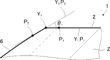
角度θ1を、図6に基づいて説明する。
図6は、図1の拡大図である。図1に基づいて説明した部分と同一の部分については同一の符号を用い、説明を省略する。
点P1は、第1主面2上の点であり、点Y1と点P1との距離(第1主面2に平行な方向の距離)が50μmである。点Y1と点P1とを通る直線を、直線Y1P1とする。
点P2は、第2境界面6上の点であり、点Y1と点P2との距離(第1主面2に平行な方向の距離)が50μmである。点Y1と点P2とを通る直線を、直線Y1P2とする。
直線Y1P1と直線Y1P2とのなす角度を、角度θ1とする。
図6は、図1の拡大図である。図1に基づいて説明した部分と同一の部分については同一の符号を用い、説明を省略する。
点P1は、第1主面2上の点であり、点Y1と点P1との距離(第1主面2に平行な方向の距離)が50μmである。点Y1と点P1とを通る直線を、直線Y1P1とする。
点P2は、第2境界面6上の点であり、点Y1と点P2との距離(第1主面2に平行な方向の距離)が50μmである。点Y1と点P2とを通る直線を、直線Y1P2とする。
直線Y1P1と直線Y1P2とのなす角度を、角度θ1とする。
〈化学強化ガラス〉
ガラス基体1は、カバーガラスとして用いられる場合、化学強化処理が施されたガラス(化学強化ガラス)であることが好ましい。
化学強化ガラスの表面層には、圧縮応力層が形成される。
圧縮応力層の深さ(DOL)は、10μm以上が好ましく、15μm以上がより好ましく、25μm以上が更に好ましい。
圧縮応力層の圧縮応力値(CS)は、500MPa以上が好ましく、650MPa以上がより好ましく、750MPa以上が更に好ましい。一方、1200MPa以下が好ましい。
圧縮応力層の圧縮応力値(CS)および圧縮応力層の深さ(DOL)は、例えば、表面応力計(FSM-6000、折原製作所社製)または散乱光光弾性応力計(SLP-2000、折原製作所社製)を用いて計測できる。
〈機能層〉
ガラス基体1の第1主面2および/または第2主面3には、機能層が形成されていてもよい。機能層としては、例えば、反射防止層、アンチグレア層(AG層)、防汚層、遮光層などが挙げられる。
機能層は、ガラス基体1の表層を処理して形成してもよく、ガラス基体1の表面に他の層を積層して形成してもよい。
ガラス基体1の第1主面2および/または第2主面3には、機能層が形成されていてもよい。機能層としては、例えば、反射防止層、アンチグレア層(AG層)、防汚層、遮光層などが挙げられる。
機能層は、ガラス基体1の表層を処理して形成してもよく、ガラス基体1の表面に他の層を積層して形成してもよい。
〈板厚、形状および大きさ〉
ガラス基体1の板厚は、0.5mm以上2.5mm以下が好ましく、0.7mm以上2.0mm以下がより好ましい。
ガラス基体1の主面(第1主面2および第2主面3)の形状および大きさは、例えば、使用される車載表示装置21の形状等に合わせて適宜決定される。
ガラス基体1の板厚は、0.5mm以上2.5mm以下が好ましく、0.7mm以上2.0mm以下がより好ましい。
ガラス基体1の主面(第1主面2および第2主面3)の形状および大きさは、例えば、使用される車載表示装置21の形状等に合わせて適宜決定される。
〈屈曲部〉
図3は、ガラス基体1の変形例を示す断面図である。
図1では、ガラス基体1を平坦な板状のガラスとして図示したが、ガラス基体1の形状としてはこれに限定されない。
例えば、図3に示すように、ガラス基体1は、屈曲部12を有していてもよい。屈曲部12においては、第1主面2が凹状に屈曲(湾曲)し、他方の第2主面3が凸状に屈曲(湾曲)している。
ガラス基体1が屈曲部12を有する場合、屈曲部12の曲率半径は、例えば、10mm以上100mm以下である。
なお、屈曲部12においては、反対に、第1主面2が凸状に屈曲し、第2主面3が凹状に屈曲していてもよい。
図3は、ガラス基体1の変形例を示す断面図である。
図1では、ガラス基体1を平坦な板状のガラスとして図示したが、ガラス基体1の形状としてはこれに限定されない。
例えば、図3に示すように、ガラス基体1は、屈曲部12を有していてもよい。屈曲部12においては、第1主面2が凹状に屈曲(湾曲)し、他方の第2主面3が凸状に屈曲(湾曲)している。
ガラス基体1が屈曲部12を有する場合、屈曲部12の曲率半径は、例えば、10mm以上100mm以下である。
なお、屈曲部12においては、反対に、第1主面2が凸状に屈曲し、第2主面3が凹状に屈曲していてもよい。
〈用途〉
ガラス基体1の用途は、特に限定されず、例えば、表示装置のカバーガラスとして用いられ、なかでも、車載表示装置21のカバーガラスとして好適に用いられる。
ガラス基体1の用途は、特に限定されず、例えば、表示装置のカバーガラスとして用いられ、なかでも、車載表示装置21のカバーガラスとして好適に用いられる。
[ガラス基体の製造方法]
次に、上述したガラス基体1を製造する方法(以下、便宜的に「本製造方法」ともいう)について説明する。
次に、上述したガラス基体1を製造する方法(以下、便宜的に「本製造方法」ともいう)について説明する。
〈ガラス板の準備〉
まず、ガラス板31を準備する。ガラス板31は、一方の主面である第1主面32、他方の主面である第2主面33、および、第1主面32と第2主面33とに接続する端面34を有する。
ガラス板31の第1主面32が、ガラス基体1の第1主面2となる。ガラス板31の第2主面33が、ガラス基体1の第2主面3となる。
ガラス板31の板厚は、上述したガラス基体1の板厚と同じである。
まず、ガラス板31を準備する。ガラス板31は、一方の主面である第1主面32、他方の主面である第2主面33、および、第1主面32と第2主面33とに接続する端面34を有する。
ガラス板31の第1主面32が、ガラス基体1の第1主面2となる。ガラス板31の第2主面33が、ガラス基体1の第2主面3となる。
ガラス板31の板厚は、上述したガラス基体1の板厚と同じである。
ガラス板31のガラス種としては、例えば、ソーダライムガラス、アルミノシリケートガラス(SiO2-Al2O3-Na2O系ガラス)等が挙げられる。
ガラス板31のガラス組成としては、例えば、日本国特開2019-006650号公報の段落[0019]に記載されたガラス組成が挙げられる。
後述する化学強化処理を施す場合は、例えば、アルミノシリケートガラスをベースとする化学強化用ガラス(ドラゴントレイル(登録商標)、AGC社製)が好適に用いられる。
ガラス板31のガラス組成としては、例えば、日本国特開2019-006650号公報の段落[0019]に記載されたガラス組成が挙げられる。
後述する化学強化処理を施す場合は、例えば、アルミノシリケートガラスをベースとする化学強化用ガラス(ドラゴントレイル(登録商標)、AGC社製)が好適に用いられる。
〈研削〉
図4は、回転砥石35を用いたガラス板31の研削を示す断面図である。
次に、図4に示すように、回転砥石35を用いて、ガラス板31の端部を研削する。これにより、ガラス板31に対して、いわゆる面取りが行なわれる。
回転砥石35の外周面である研削面36には、周方向に延びる環状の研削溝が形成されている。研削面36は、アルミナ、炭化ケイ素、ダイヤモンドなどの砥粒を含む。砥粒の粒度(JIS R 6001)は、特に限定されないが、例えば#300から#2000までの範囲から選択される。
回転砥石35は、回転砥石35の中心線を中心に回転しながら、ガラス板31の端部に沿って相対的に移動し、ガラス板31の端部を研削面36で研削する。研削に際しては水などの冷却液が用いられてもよい。
そして、本製造方法においては、回転砥石35の研削面36が、少なくとも、所望するガラス基体1の面取り部(第1境界面5および第2境界面6)の形状に対応する形状を有する(ただし、図4は、模式図であるため、そのような形状にはなっていない)。このような回転砥石35は、例えば特注品として入手できる。
このような回転砥石35を用いて、ガラス板31の端部を研削して面取りすることにより、上述したガラス基体1が得られる。
このような回転砥石35を用いて、ガラス板31の端部を研削して面取りすることにより、上述したガラス基体1が得られる。
図3のようなガラス基体1を得るためには、ガラス板31も屈曲していることを要する。この場合、ガラス基体1の屈曲部12の曲率半径と同じ曲率半径を有するガラス板31を用いる。
屈曲したガラス板31を研削する際に、回転砥石35の直径D1が大きすぎると、屈曲したガラス板31の凹面側において、回転砥石35の角などがガラス板31に当たって、チッピングが形成されやすい場合がある。
このため、屈曲したガラス板31を研削する場合、回転砥石35の直径D1は、ガラス板31の曲率半径よりも小さいことが好ましい。これにより、チッピングの形成が抑制される。回転砥石の直径D1は、砥石周速を考慮して、5~30mmが好ましい。
屈曲したガラス板31を研削する際に、回転砥石35の直径D1が大きすぎると、屈曲したガラス板31の凹面側において、回転砥石35の角などがガラス板31に当たって、チッピングが形成されやすい場合がある。
このため、屈曲したガラス板31を研削する場合、回転砥石35の直径D1は、ガラス板31の曲率半径よりも小さいことが好ましい。これにより、チッピングの形成が抑制される。回転砥石の直径D1は、砥石周速を考慮して、5~30mmが好ましい。
なお、最終的に、上述したガラス基体1が得られるのであれば、まず粒度が粗い回転砥石を用いて粗加工し、その後、粒度が細かい回転砥石を用いて仕上げ加工してもよい。
また、上述したガラス基体1が得られるのであれば、回転砥石以外の研削用具を用いて研削してもよい。ただし、生産性の観点からは、回転砥石が好ましい。
〈化学強化処理〉
研削後のガラス板31に、化学強化処理を施してもよい。この場合、化学強化処理が施されたガラス板31が、ガラス基体1となる。
化学強化処理を施す場合、ガラス板31として、化学強化用ガラスを用いる。
化学強化処理では、従来公知の方法を採用でき、典型的には、ガラス板31を、溶融塩に浸漬させる。これにより、ガラス板31の表層において、アルカリイオン(Liイオンおよび/またはNaイオン)を、溶融塩中のイオン半径の大きい他のアルカリイオン(Naイオンおよび/またはKイオン)とイオン交換(置換)する。このイオン交換によって、ガラス板31の表層に、高密度化によって圧縮応力が発生した層(圧縮応力層)を形成する。こうして、ガラス板31を強化できる。
ガラス板31に含まれるアルカリイオンがNaイオンである場合、溶融塩(無機塩組成物)は、硝酸カリウム(KNO3)を含有することが好ましい。
溶融塩の温度や浸漬時間などの処理条件は、圧縮応力層の圧縮応力値(CS)および圧縮応力層の厚さ(DOL)などが所望の値となるように設定すればよい。
なお、本製造方法では、適宜、ガラス基体1の第1主面2および/または第2主面3に、機能層を形成してもよい。
以下に、実施例等により本発明の実施形態を具体的に説明する。ただし、本発明は以下の例に限定されない。以下、例1~例4および例7が実施例であり、例5~例6が比較例である。
〈例1〉
ガラス板31として、AGC社製「ドラゴントレイル」を準備した。ガラス板31の主面(第1主面32および第2主面33)のサイズは1200mm×300mmであった。ガラス板31の板厚は2.0mmであった。
ガラス板31は、第1主面32が凹状となる向きに屈曲しており、ガラス板31の曲率半径は、50mmであった。
ガラス板31として、AGC社製「ドラゴントレイル」を準備した。ガラス板31の主面(第1主面32および第2主面33)のサイズは1200mm×300mmであった。ガラス板31の板厚は2.0mmであった。
ガラス板31は、第1主面32が凹状となる向きに屈曲しており、ガラス板31の曲率半径は、50mmであった。
次に、準備したガラス板31の端部を、特定の研削面36を有する特注品である回転砥石35を用いて研削することにより、例1のガラス基体1を得た。
回転砥石35の直径D1は20mmであった。回転砥石35の研削面36の砥粒は、粒度が#800のダイヤモンドであった。
研削は湿式で行なった。すなわち、研削に際しては、冷却水として水を用いた。
回転砥石35の直径D1は20mmであった。回転砥石35の研削面36の砥粒は、粒度が#800のダイヤモンドであった。
研削は湿式で行なった。すなわち、研削に際しては、冷却水として水を用いた。
回転砥石35の研削によりガラス板31の面取りが行なわれ、端面4、第1境界面5、第2境界面6、第3境界面7および第4境界面8が形成された。
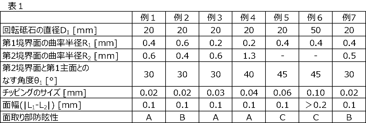
第1境界面5の曲率半径R1、第2境界面6の曲率半径R2、第2境界面6と第1主面2とのなす角度θ1、第2境界面6のチッピングのサイズ、および、面幅(|L1-L2|)を、下記表1に示す(後述する例2~例7においても同様)。
第1境界面5の曲率半径R1、第2境界面6の曲率半径R2、第2境界面6と第1主面2とのなす角度θ1、第2境界面6のチッピングのサイズ、および、面幅(|L1-L2|)を、下記表1に示す(後述する例2~例7においても同様)。
〈例2~例7〉
例2~例7では、それぞれ、例1とは研削面36の形状が異なる回転砥石35を用いてガラス板31の研削を行ない、ガラス基体1を得た。
なお、例5~例6では、第2境界面6として、湾曲面ではなく、湾曲していない平坦面を形成した。このため、下記表1における第2境界面6の曲率半径R2の欄には、「-」を記載した。
また、例6では、例1~例5とは異なり、回転砥石35の直径D1は50mmとした。
例2~例7では、それぞれ、例1とは研削面36の形状が異なる回転砥石35を用いてガラス板31の研削を行ない、ガラス基体1を得た。
なお、例5~例6では、第2境界面6として、湾曲面ではなく、湾曲していない平坦面を形成した。このため、下記表1における第2境界面6の曲率半径R2の欄には、「-」を記載した。
また、例6では、例1~例5とは異なり、回転砥石35の直径D1は50mmとした。
〈評価〉
例1~例7のそれぞれのガラス基体1を用いて、年齢が30代から60代までの被験者11人に、以下の評価をしてもらった。
まず、被験者には、光が当てられているガラス基体1を、第1主面2と対面する向きで60cm離して持ってもらい、様々な角度からガラス基体1の面取り部(第1境界面5および第2境界面6)を見てもらった。そして、面取り部からの反射光が最も強いと感じる角度Aを決めてもらった。
このとき、ガラス基体1に当てる光の照度を、1000ルクス(蛍光灯の明りに相当)から順に、15000ルクス(晴天時の日陰を少し超える照度に相当)まで変化させた。被験者には、角度Aにおいて、ガラス基体1の面取り部からの反射光が眩しいと感じたときの照度を記録してもらった。
被験者11人のそれぞれが眩しいと感じたときの照度の平均値(以下、本段落において単に「照度」という)を求めた。下記表1には、照度が4000ルクス未満の場合は「C」を、照度が4000ルクス以上8000ルクス未満の場合は「B」を、照度が8000ルクス以上の場合は「A」を記載した。照度が大きいほど、ガラス基体1の面取り部からの反射光による眩しさが抑制されており、面取り部防眩性に優れると評価できる。
〈評価結果まとめ〉
上記表1に示す結果から明らかなように、第2境界面6が平坦面である例5~例6と比較して、例1~例4および例7は、面取り部防眩性に優れていた。
上記表1に示す結果から明らかなように、第2境界面6が平坦面である例5~例6と比較して、例1~例4および例7は、面取り部防眩性に優れていた。
例1と例2とを対比すると、曲率半径R1が曲率半径R2より大きい例2よりも、曲率半径R2が曲率半径R1よりも大きい例1の方が、面取り部防眩性がより優れていた。
曲率半径R2のみが異なる例1と例7とを対比すると、曲率半径R2が0.5mmである例7よりも、曲率半径R2が0.6mmである例1の方が、面取り部防眩性がより優れていた。
曲率半径R2のみが異なる例1と例7とを対比すると、曲率半径R2が0.5mmである例7よりも、曲率半径R2が0.6mmである例1の方が、面取り部防眩性がより優れていた。
本発明を詳細にまた特定の実施形態を参照して説明したが、本発明の精神と範囲を逸脱することなく様々な変更や修正を加えることができることは当業者にとって明らかである。本出願は、2019年7月10日出願の日本特許出願(特願2019-128071)に基づくものであり、その内容はここに参照として取り込まれる。
1:ガラス基体
2:第1主面
3:第2主面
4:端面
5:第1境界面
6:第2境界面
7:第3境界面
8:第4境界面
12:屈曲部
21:車載表示装置
22:筐体
23:バックライトユニット
24:表示パネル
25:粘着層
31:ガラス板
32:ガラス板の第1主面
33:ガラス板の第2主面
34:ガラス板の端面
35:回転砥石
36:研削面
D1:回転砥石の直径
R1:第1境界面の曲率半径
R2:第2境界面の曲率半径
θ1:第2境界面と第1主面とのなす角度
L1:端面から第1主面までの、端面から第1主面に対して接線方向の長さ
L2:端面から第2主面までの、端面から第2主面に対して接線方向の長さ
2:第1主面
3:第2主面
4:端面
5:第1境界面
6:第2境界面
7:第3境界面
8:第4境界面
12:屈曲部
21:車載表示装置
22:筐体
23:バックライトユニット
24:表示パネル
25:粘着層
31:ガラス板
32:ガラス板の第1主面
33:ガラス板の第2主面
34:ガラス板の端面
35:回転砥石
36:研削面
D1:回転砥石の直径
R1:第1境界面の曲率半径
R2:第2境界面の曲率半径
θ1:第2境界面と第1主面とのなす角度
L1:端面から第1主面までの、端面から第1主面に対して接線方向の長さ
L2:端面から第2主面までの、端面から第2主面に対して接線方向の長さ
Claims (10)
- 第1主面と、
前記第1主面とは反対側の主面である第2主面と、
前記第1主面および前記第2主面に挟まれた端面と、
前記第1主面と前記端面との間に配置され、前記端面に接続する第1境界面と、
前記第1主面と前記第1境界面とに接続する第2境界面と、を備え、
前記第2境界面が、凸状に湾曲した湾曲面であり、
前記第2境界面の曲率半径R2が0.1mm以上2.0mm以下である、ガラス基体。 - 前記第2境界面と前記第1主面とのなす角度θ1が10°以上45°以下である、請求項1に記載のガラス基体。
- 前記第1境界面が、凸状に湾曲した湾曲面であり、
前記第1境界面の曲率半径R1が0.1mm以上1.0mm以下である、請求項1または2に記載のガラス基体。 - 前記第1境界面の曲率半径R1よりも、前記第2境界面の曲率半径R2の方が大きい、請求項3に記載のガラス基体。
- 前記第1主面および前記第2主面が屈曲した屈曲部を有する、請求項1~4のいずれか1項に記載のガラス基体。
- 前記第2境界面におけるチッピングのサイズが、0.08mm以下である、請求項1~5のいずれか1項に記載のガラス基体。
- 前記端面から前記第1主面までの、前記端面から前記第1主面に対して接線方向の長さL1と、前記端面から前記第2主面までの、前記端面から前記第2主面に対して接線方向の長さL2との差が、0.2mm以下である、請求項1~6のいずれか1項に記載のガラス基体。
- 表示装置のカバーガラスとして用いられる、請求項1~7のいずれか1項に記載のガラス基体。
- 前記表示装置が、車載表示装置である、請求項8に記載のガラス基体。
- 請求項1~9のいずれか1項に記載のガラス基体を製造する方法であって、
ガラス板を準備し、
回転砥石を用いて、前記ガラス板を研削し、
前記回転砥石の研削面は、前記第1境界面および前記第2境界面の形状に対応する形状を有する、ガラス基体の製造方法。
Priority Applications (4)
| Application Number | Priority Date | Filing Date | Title |
|---|---|---|---|
| EP20836632.8A EP3998245A4 (en) | 2019-07-10 | 2020-06-30 | GLASS SUBSTRATE AND METHOD OF MANUFACTURING THEREOF |
| CN202080049981.2A CN114080371B (zh) | 2019-07-10 | 2020-06-30 | 玻璃基体以及其制造方法 |
| JP2021530624A JPWO2021006116A1 (ja) | 2019-07-10 | 2020-06-30 | |
| US17/571,184 US20220126416A1 (en) | 2019-07-10 | 2022-01-07 | Glass substrate and method for manufacturing same |
Applications Claiming Priority (2)
| Application Number | Priority Date | Filing Date | Title |
|---|---|---|---|
| JP2019128071 | 2019-07-10 | ||
| JP2019-128071 | 2019-07-10 |
Related Child Applications (1)
| Application Number | Title | Priority Date | Filing Date |
|---|---|---|---|
| US17/571,184 Continuation US20220126416A1 (en) | 2019-07-10 | 2022-01-07 | Glass substrate and method for manufacturing same |
Publications (1)
| Publication Number | Publication Date |
|---|---|
| WO2021006116A1 true WO2021006116A1 (ja) | 2021-01-14 |
Family
ID=74115229
Family Applications (1)
| Application Number | Title | Priority Date | Filing Date |
|---|---|---|---|
| PCT/JP2020/025670 WO2021006116A1 (ja) | 2019-07-10 | 2020-06-30 | ガラス基体およびその製造方法 |
Country Status (6)
| Country | Link |
|---|---|
| US (1) | US20220126416A1 (ja) |
| EP (1) | EP3998245A4 (ja) |
| JP (1) | JPWO2021006116A1 (ja) |
| CN (1) | CN114080371B (ja) |
| TW (1) | TW202106651A (ja) |
| WO (1) | WO2021006116A1 (ja) |
Families Citing this family (1)
| Publication number | Priority date | Publication date | Assignee | Title |
|---|---|---|---|---|
| FR3139135A1 (fr) * | 2022-08-31 | 2024-03-01 | Saint-Gobain Glass France | Feuille de verre usinée et procédé d’usinage associé |
Citations (10)
| Publication number | Priority date | Publication date | Assignee | Title |
|---|---|---|---|---|
| JP2001191238A (ja) * | 1999-12-28 | 2001-07-17 | Koyo Mach Ind Co Ltd | 円盤状工作物の面取り加工方法、面取り用研削砥石車および面取り加工装置 |
| JP2011108355A (ja) * | 2010-12-20 | 2011-06-02 | Hoya Corp | 磁気記録媒体用ガラス基板及びその製造方法 |
| WO2012005019A1 (ja) * | 2010-07-08 | 2012-01-12 | 旭硝子株式会社 | ガラス基板端面の評価方法及びガラス基板端面の加工方法並びにガラス基板 |
| JP2012526040A (ja) * | 2009-05-08 | 2012-10-25 | コーニング インコーポレイテッド | ポリマーの外側被覆を有するガラス物品およびその形成方法 |
| WO2013031548A1 (ja) * | 2011-08-29 | 2013-03-07 | 旭硝子株式会社 | ガラス板 |
| JP2015058507A (ja) * | 2013-09-19 | 2015-03-30 | 旭硝子株式会社 | レジンボンド砥石の研磨用溝の作製方法及びレジンボンド砥石並びに板状体の加工装置及び板状体の加工方法 |
| JP2017120416A (ja) * | 2015-12-29 | 2017-07-06 | Hoya株式会社 | フォトマスク基板、フォトマスクブランク、フォトマスク、フォトマスク基板の製造方法、フォトマスクの製造方法、及び表示装置の製造方法 |
| WO2017208995A1 (ja) | 2016-05-31 | 2017-12-07 | 旭硝子株式会社 | カバーガラスおよび表示装置 |
| JP2019006650A (ja) | 2017-06-27 | 2019-01-17 | Agc株式会社 | 化学強化ガラスの製造方法及び化学強化ガラス |
| JP2019128071A (ja) | 2018-01-23 | 2019-08-01 | 三菱電機株式会社 | 空気調和装置 |
Family Cites Families (5)
| Publication number | Priority date | Publication date | Assignee | Title |
|---|---|---|---|---|
| JP4274708B2 (ja) * | 2001-05-14 | 2009-06-10 | Hoya株式会社 | 磁気記録媒体用ガラス基板及びその製造方法 |
| WO2010104039A1 (ja) * | 2009-03-10 | 2010-09-16 | 日本電気硝子株式会社 | ガラス基板およびその製造方法 |
| KR101755062B1 (ko) * | 2010-06-21 | 2017-07-06 | 아사히 가라스 가부시키가이샤 | 유리 기판 및 유리 기판의 제조 방법 |
| KR20140063610A (ko) * | 2011-08-29 | 2014-05-27 | 아사히 가라스 가부시키가이샤 | 유리판 및 유리판의 제조 방법 |
| KR20180041133A (ko) * | 2015-08-19 | 2018-04-23 | 아사히 가라스 가부시키가이샤 | 유리판 |
-
2020
- 2020-06-30 JP JP2021530624A patent/JPWO2021006116A1/ja active Pending
- 2020-06-30 WO PCT/JP2020/025670 patent/WO2021006116A1/ja unknown
- 2020-06-30 EP EP20836632.8A patent/EP3998245A4/en active Pending
- 2020-06-30 CN CN202080049981.2A patent/CN114080371B/zh active Active
- 2020-07-08 TW TW109123028A patent/TW202106651A/zh unknown
-
2022
- 2022-01-07 US US17/571,184 patent/US20220126416A1/en active Pending
Patent Citations (10)
| Publication number | Priority date | Publication date | Assignee | Title |
|---|---|---|---|---|
| JP2001191238A (ja) * | 1999-12-28 | 2001-07-17 | Koyo Mach Ind Co Ltd | 円盤状工作物の面取り加工方法、面取り用研削砥石車および面取り加工装置 |
| JP2012526040A (ja) * | 2009-05-08 | 2012-10-25 | コーニング インコーポレイテッド | ポリマーの外側被覆を有するガラス物品およびその形成方法 |
| WO2012005019A1 (ja) * | 2010-07-08 | 2012-01-12 | 旭硝子株式会社 | ガラス基板端面の評価方法及びガラス基板端面の加工方法並びにガラス基板 |
| JP2011108355A (ja) * | 2010-12-20 | 2011-06-02 | Hoya Corp | 磁気記録媒体用ガラス基板及びその製造方法 |
| WO2013031548A1 (ja) * | 2011-08-29 | 2013-03-07 | 旭硝子株式会社 | ガラス板 |
| JP2015058507A (ja) * | 2013-09-19 | 2015-03-30 | 旭硝子株式会社 | レジンボンド砥石の研磨用溝の作製方法及びレジンボンド砥石並びに板状体の加工装置及び板状体の加工方法 |
| JP2017120416A (ja) * | 2015-12-29 | 2017-07-06 | Hoya株式会社 | フォトマスク基板、フォトマスクブランク、フォトマスク、フォトマスク基板の製造方法、フォトマスクの製造方法、及び表示装置の製造方法 |
| WO2017208995A1 (ja) | 2016-05-31 | 2017-12-07 | 旭硝子株式会社 | カバーガラスおよび表示装置 |
| JP2019006650A (ja) | 2017-06-27 | 2019-01-17 | Agc株式会社 | 化学強化ガラスの製造方法及び化学強化ガラス |
| JP2019128071A (ja) | 2018-01-23 | 2019-08-01 | 三菱電機株式会社 | 空気調和装置 |
Non-Patent Citations (1)
| Title |
|---|
| See also references of EP3998245A4 |
Also Published As
| Publication number | Publication date |
|---|---|
| EP3998245A1 (en) | 2022-05-18 |
| CN114080371B (zh) | 2024-01-02 |
| TW202106651A (zh) | 2021-02-16 |
| JPWO2021006116A1 (ja) | 2021-01-14 |
| US20220126416A1 (en) | 2022-04-28 |
| CN114080371A (zh) | 2022-02-22 |
| EP3998245A4 (en) | 2023-08-02 |
Similar Documents
| Publication | Publication Date | Title |
|---|---|---|
| US10766222B2 (en) | Glass substrate and method for manufacturing the same, cover glass and method for manufacturing the same, personal digital assistant, and display device | |
| CN110054418B (zh) | 玻璃板和显示装置 | |
| JP6833165B2 (ja) | 輸送機用内装組立体 | |
| CN215340409U (zh) | 包含光学涂层的制品 | |
| JP6687044B2 (ja) | 曲面カバーガラス及びその製造方法、並びに車載用表示部材 | |
| JP7092137B2 (ja) | カバー部材および携帯情報端末 | |
| CN206143062U (zh) | 保护玻璃以及便携式信息终端 | |
| WO2019159983A1 (ja) | カバーガラス、およびインセル型液晶表示装置 | |
| US10775657B2 (en) | Transparent substrate and display device | |
| US20180071881A1 (en) | Method for manufacturing glass plate, glass plate, and display device | |
| TWI572947B (zh) | 具有光擴散玻璃面板之顯示裝置 | |
| WO2021006116A1 (ja) | ガラス基体およびその製造方法 | |
| WO2020255926A1 (ja) | ガラス基体 | |
| US20170260079A1 (en) | Pre-compressed glass article | |
| WO2022149512A1 (ja) | ガラス板、表示装置及びガラス板の製造方法 | |
| TW201714852A (zh) | 玻璃板 | |
| TW202110766A (zh) | 具有受控色彩的低反射率、防反射的膜結構及具有該等膜結構的製品 | |
| JP2018016513A (ja) | ガラス部材およびガラス部材の製造方法 |
Legal Events
| Date | Code | Title | Description |
|---|---|---|---|
| 121 | Ep: the epo has been informed by wipo that ep was designated in this application |
Ref document number: 20836632 Country of ref document: EP Kind code of ref document: A1 |
|
| ENP | Entry into the national phase |
Ref document number: 2021530624 Country of ref document: JP Kind code of ref document: A |
|
| ENP | Entry into the national phase |
Ref document number: 2020836632 Country of ref document: EP Effective date: 20220210 |