WO2021005390A1 - 金属樹脂複合体及び該金属樹脂複合体の製造方法 - Google Patents
金属樹脂複合体及び該金属樹脂複合体の製造方法 Download PDFInfo
- Publication number
- WO2021005390A1 WO2021005390A1 PCT/IB2019/000671 IB2019000671W WO2021005390A1 WO 2021005390 A1 WO2021005390 A1 WO 2021005390A1 IB 2019000671 W IB2019000671 W IB 2019000671W WO 2021005390 A1 WO2021005390 A1 WO 2021005390A1
- Authority
- WO
- WIPO (PCT)
- Prior art keywords
- resin
- metal
- metal plate
- resin composite
- exposed portion
- Prior art date
- Legal status (The legal status is an assumption and is not a legal conclusion. Google has not performed a legal analysis and makes no representation as to the accuracy of the status listed.)
- Ceased
Links
Images



Classifications
-
- B—PERFORMING OPERATIONS; TRANSPORTING
- B29—WORKING OF PLASTICS; WORKING OF SUBSTANCES IN A PLASTIC STATE IN GENERAL
- B29C—SHAPING OR JOINING OF PLASTICS; SHAPING OF MATERIAL IN A PLASTIC STATE, NOT OTHERWISE PROVIDED FOR; AFTER-TREATMENT OF THE SHAPED PRODUCTS, e.g. REPAIRING
- B29C45/00—Injection moulding, i.e. forcing the required volume of moulding material through a nozzle into a closed mould; Apparatus therefor
- B29C45/14—Injection moulding, i.e. forcing the required volume of moulding material through a nozzle into a closed mould; Apparatus therefor incorporating preformed parts or layers, e.g. injection moulding around inserts or for coating articles
-
- B—PERFORMING OPERATIONS; TRANSPORTING
- B32—LAYERED PRODUCTS
- B32B—LAYERED PRODUCTS, i.e. PRODUCTS BUILT-UP OF STRATA OF FLAT OR NON-FLAT, e.g. CELLULAR OR HONEYCOMB, FORM
- B32B15/00—Layered products comprising a layer of metal
- B32B15/04—Layered products comprising a layer of metal comprising metal as the main or only constituent of a layer, which is next to another layer of the same or of a different material
- B32B15/08—Layered products comprising a layer of metal comprising metal as the main or only constituent of a layer, which is next to another layer of the same or of a different material of synthetic resin
Definitions
- the present invention relates to a metal-resin composite in which a metal plate and a resin are directly bonded, and more particularly to a metal-resin composite having a portion that can be welded to another metal member or the like.
- the weight of the vehicle is reduced by using a composite of resin and metal member, and an adhesive is often used to bond the resin and metal member.
- a through hole may be formed in the metal member, and the thermoplastic resin may be continuously formed from one side surface to the other side surface of the metal member through the through hole to join the metal member and the thermoplastic resin. It is done. However, when the through holes are formed in the metal member, the thermoplastic resin is exposed on the design surface constituting the appearance of the metal resin composite, and the design property is deteriorated.
- the surface of the metal member is roughened by sandblasting or the like to improve the joint strength between the metal member and the resin.
- the holes formed by sandblasting are mortar-shaped and the opening diameter is wider than the diameter of the bottom, a large anchor effect is not exhibited, and when the metal member bends, it easily peels off, and the metal plate and resin that are thin and easily bend. It is not suitable for joining.
- Patent Document 1 describes an injection molding method or compression on an aluminum substrate whose surface has been pretreated by acid treatment, soda treatment, amine treatment, anodizing, base treatment or laser treatment.
- a lightweight member having a hybrid design in which a thermoplastic resin is applied by molding or the like and the thermoplastic resin and an aluminum base material are joined is described.
- thermoplastic resin can be bonded to the surface of the aluminum base material without forming through holes in the aluminum base material or wrapping the periphery of the aluminum base material with the resin. It is possible to prevent deterioration of design.
- the reaction proceeds at the boundary between the bottom of the pores of the oxide film generated on the aluminum surface and aluminum, and independent pores (hexagonal column model) with the same degree of opening diameter and inner diameter. ) Is believed to be formed. Since the thermoplastic resin that has penetrated into the pores is easily removed without being caught on the inner wall of the pores, it is peeled off at the interface between the thermoplastic resin and the aluminum base material.
- thermoplastic resin and the aluminum group that have penetrated into the pores The material does not bite. Therefore, the infiltrated thermoplastic resin is easily removed and the bonding strength is insufficient, and the thermoplastic resin and the aluminum base material are peeled off at the interface.
- the present inventors immerse the metal plate in a predetermined surface treatment liquid to roughen the surface of the metal plate with a nano-sized porous structure, and infiltrate the resin into the nano-sized porous structure to separate the metal plate and the resin. It was decided to secure the joint strength by occluding and joining.
- a metal plate having a nano-sized porous structure formed by being immersed in a predetermined surface treatment liquid has the nano-sized porous structure formed on the entire surface, and is a flange for welding with other metal members or the like during molding. If the resin leaks to a part or the like where the resin is not desired to be applied, it is very difficult to remove the excess resin from the bonding strength. Even if the resin is forcibly peeled off, the resin is not peeled off at the interface between the metal plate and the resin, the resin is broken, and the resin remains on the surface of the metal plate, so that welding cannot be performed.
- metal plates are prone to deformation due to their thickness, making high-precision press molding difficult, so the metal plates placed in the mold are prone to distortion. Further, when the resin is applied to the metal plate, the metal plate tends to move or tilt in the mold due to the injection pressure or the pressing pressure, and the resin easily leaks to a place other than the desired portion of the metal plate.
- the present invention has been made in view of such a problem, and an object of the present invention is an extra resin in a portion of a metal plate having a nano-sized porous structure and a rough surface, to which resin is not desired to be applied. It is an object of the present invention to provide a metal-resin composite in which the excess resin can be easily removed even if the resin leaks.
- the present inventor has formed a nano-sized porous structure on the coating portion of the metal plate and does not form the nano-sized porous structure on the exposed portion. We have found that this can be achieved, and have completed the present invention.
- the metal-resin composite of the present invention includes a metal plate and a resin that directly coats the metal plate. Then, one main surface of the metal plate has a coated portion coated with the resin and an exposed portion exposed from the resin, and the roughening rate of the coated portion is higher than that of the exposed portion. It is a feature.
- the method for producing a metal-resin composite of the present invention is a method for producing a metal-resin composite having a coating portion directly coated with a resin and an exposed portion exposed from the resin on one main surface of a metal plate. is there. Then, an integration step of applying the resin to one main surface of a metal plate having a different roughening ratio on one main surface and integrating the metal plate and the resin. It is characterized by comprising a removing step of removing the resin from a portion of the metal plate having a low roughening rate.
- the roughening ratio of the metal plate is made higher than that of the exposed portion exposed from the resin in the coated portion directly coated with the resin, so that the exposed portion to which the resin is not desired to be applied is extra in the molding. It is possible to provide a metal resin composite in which the excess resin can be easily removed even if the resin leaks.
- the metal-resin composite of the present invention will be described in detail.
- the metal-resin composite includes a metal plate and a resin that directly coats the metal plate, and one main surface of the metal plate is a covering portion coated with the resin and an exposed portion exposed from the resin. And have. In the metal plate, the roughening rate of the covering portion is higher than that of the exposed portion.
- the "roughening rate" in the present invention is roughened by a porous structure (hereinafter, may be referred to as "nanoporous structure”) formed by gathering a plurality of holes having an average opening diameter of 10 nm to 100 nm.
- the ratio refers to the ratio of the portion roughened by an independent hole having the same opening diameter and the inner diameter, or a mortar-shaped independent hole having an opening wider than the bottom, and is not included in the roughening ratio.
- the cross section of an arbitrary portion 1 cm or more away from the boundary between the covering portion and the exposed portion is observed at 5 points or more, and the area ratio of the portion where the nanoporous structure is formed in each visual field to the metal plate surface ( The average of the width / measurement length of the nanoporous structure in cross section was taken as the roughening ratio.
- thermoplastic resin was bonded to each of the metal plate roughened to form a nanoporous structure, the metal plate roughened by sandblasting, and the metal plate not roughened as follows.
- a sample of the metal resin composite was prepared, and the bonding strength between the metal plate and the thermoplastic resin was compared. The measurement results are shown in Table 1.
- the metal resin composite was cut out so that the joint area was 0.5 cm 2 , measured with a tensile tester, and then converted into an area strength of 1.0 cm 2 .
- Example 1 An aluminum plate having a thickness of 1 mm and a surface roughness (Ra) of 0.1 ⁇ m or less, which was press-molded, was immersed in an alkaline solution to degreas it, and then immersed in an acid solution to neutralize it. The aluminum plate was immersed in a 5% aqueous solution of hydrazine monohydrate heated to 50 ° C. for 5 minutes, washed with water and dried to obtain an aluminum plate having a roughened surface.
- Ra surface roughness
- the surface of the aluminum plate was photographed with a scanning electron microscope (Hitachi High-Tech: S4700).
- the SEM image of the surface of the roughened aluminum plate is shown in FIG. 1, and the SEM image of the surface of the aluminum plate before roughening is shown in FIG.
- the roughened aluminum plate had a surface roughness (Ra) of 0.3 ⁇ m, and a nanoporous structure was formed by nano-sized pores having an average pore size of 10 nm.
- the surface roughness (Ra) of the female aluminum plate was measured according to JIS B0601-1994 using a stylus type roughness meter.
- the roughened aluminum plate is placed on a mold, pressed by the upper mold and heated to 280 ° C., and the average fiber diameter is 10 ⁇ m and the average length is 0.5 mm with the mold slightly open.
- a kneaded material of carbon fiber and nylon 6 containing 35% by mass of carbon fiber was injected. Then, the die was completely closed and pressed at 10 MPa to obtain a metal resin composite having a resin thickness of 2 mm.
- a roughened metal plate and a flaky sample of a metal resin composite were prepared.
- the presence or absence of a nanoporous structure was observed using a transmission electron microscope (JEOL: JEM-F200, observation conditions: acceleration voltage 200 kV, field of view: 700 nm ⁇ 700 nm).
- TEM transmission electron microscope
- an energy dispersive X-ray spectroscopic analyzer manufactured by JEOL: Dual SDD (attached to JEM-F200), analysis conditions: elemental analysis of the cross section of the metal resin composite was performed at an acceleration voltage of 200 kV.
- thermoplastic resin 3 is filled in the entire space of the nanoporous structure 23 formed on the aluminum plate, and the thermoplastic resin 3 is impregnated to a depth of 450 nm. There were no filling defects.
- the nanoporous structure 23 formed on the aluminum plate has a plurality of micro-sized holes having an inner diameter larger than the opening diameter and an opening diameter of 1 ⁇ m or more, and the micro-sized holes are formed. It was confirmed that a plurality of nano-sized holes having an opening diameter of 10 nm to 100 nm were formed on the wall surface, and the plurality of micro-sized holes were internally connected to form an internal space in the shape of an ant's nest. ..
- the resin 3 that has penetrated into the nanoporous structure 23 does not peel off from the metal plate unless it breaks, so that the bonding strength is dramatically improved. On the other hand, if the resin 3 is forcibly peeled off, the resin 3 breaks and becomes nanoporous. Since the resin remains in the structure 23, the resin 3 cannot be removed from the metal plate 2.
- Example 2 A metal resin composite was obtained in the same manner as in Sample 1, except that an aluminum plate having a surface roughness (Ra) of 7 ⁇ m was used for roughening by sandblasting. The roughening ratio of the aluminum plate of sample 2 was 0%.
- Example 3 A metal resin composite was obtained in the same manner as in Sample 1 except that the aluminum plate was not roughened. The roughening ratio of the aluminum plate of Sample 3 was 0%.
- the joint strength of the sandblasted sample 2 is only 2.5 times that of the sample 3 without the roughening treatment.
- the bonding strength with respect to the sample 3 is improved by 21 times, and it can be seen that the metal plate and the resin are bonded very strongly.
- the bonding strength between the metal plate and the resin is improved. If the resin is forcibly peeled off from such a metal plate, the resin tends to remain on the surface of the metal plate, making welding difficult.
- the nanoporous structure is formed in the coating portion coated with the resin, and the roughening ratio of the coating portion is higher than that of the exposed portion such as a metal flange that enables welding with other metal members or the like. Use a high metal plate.
- Such a metal plate having a higher roughening ratio of the covering portion than the exposed portion can easily remove excess resin even if the resin leaks to the exposed portion when producing the metal resin composite. It is possible to weld and join a lightweight and high-strength metal-resin composite to another metal member.
- the roughening ratio of the covering portion is preferably 80% or more. Further, the roughening ratio of the exposed portion is preferably 20% or less, more preferably 10% or less, and further preferably 0%, that is, no nanoporous structure is formed.
- the roughening rate is 80% or more, the metal plate and the resin are firmly bonded. Further, when the roughening ratio is 20% or less, excess resin can be removed more easily, and the resin peeled from the surface of the metal plate has nano-sized holes or micro-sized holes on the surface of the metal plate. Even if it remains in the hole, the resin does not remain in the non-roughened portion, so that welding can be performed more easily.
- the roughening rate of the exposed portion of one main surface of the metal plate is lower than that of the covering portion, and the other main surface and side surfaces of the metal plate are formed even if the nanoporous structure is formed. It does not have to be.
- the surface roughness of the exposed portion of the metal plate is not particularly limited as long as the resin can be removed at the interface between the metal plate and the resin, but the exposed portion is smaller than the surface roughness of the coating portion from the viewpoint of easy peeling. Is preferable.
- the nanoporous structure can be carried out by masking the exposed portion of the metal plate and immersing it in an aqueous solution of ammonia, hydrazine and / or a water-soluble amine compound. Specifically, the metal plate is immersed in a 3% to 10% hydrazine monohydrate aqueous solution heated to 40 ° C. to 70 ° C. for several minutes and then washed with water to roughen the surface due to the nanoporous structure. It is possible.
- Examples of the masking material include tapes such as polyimide and silicon.
- metal plate for example, in addition to metal plates such as aluminum, iron, stainless steel, copper, titanium, magnesium, and brass, metal plates plated with the above metals can be used.
- the thickness of the metal plate depends on the required strength, but when it is 0.5 mm or more and 2.5 mm or less, it is possible to significantly reduce the weight.
- the metal-resin composite is subjected to resin on one main surface of the metal plate by an injection molding method, an injection press method, an RTM (Resin Transfer Molding) molding method, and an LFT-D (Long Fiber Thermoplastic-Direct) molding method. It can be manufactured by integrating.
- the injection press method is a method in which a resin is injected with the mold slightly open, the mold is completely closed, the injection material is pressed, and the resin is spread over the entire cavity for molding. is there. Since the molten thermoplastic resin is filled in the cavity, the thermoplastic resin adheres to the metal plate without gaps and can be firmly bonded, so that it can be preferably used.
- the molded metal plate is placed in the mold, and the thermoplastic resin is injected toward one main surface side of the metal plate with the mold slightly open. Then, the mold is completely closed and the thermoplastic resin is pressed together with the metal plate to spread the thermoplastic resin throughout the cavity, and the metal plate and the thermoplastic resin are brought into close contact with the metal resin. Make a complex.
- thermoplastic resin is injected with the mold slightly open, the metal plate is liable to float, and resin leakage is particularly liable to occur.
- metal plate is liable to float, and resin leakage is particularly liable to occur.
- resin can be easily removed.
- the carbon fiber is put into the kneader together with the thermoplastic resin, and the carbon fiber cut to an appropriate length by the shearing force of the screw and the thermoplastic resin are melt-kneaded into the LFT-D kneading material. (Composite of thermoplastic resin and carbon fiber) is produced. Then, this is a method of obtaining a molded product by press-molding the kneaded material before it cools.
- the exposed portion of the metal plate it is preferable to heat the exposed portion of the metal plate at a temperature lower than that of the covering portion. Since the temperature of the exposed portion is low, the resin leaking to the exposed portion solidifies at an early stage and dams up the resin that flows later, so that the amount of resin leaking to the exposed portion is reduced.
- thermoplastic resin can be used as the above resin.
- thermoplastic resin examples include nylon 6, nylon 66, polyphenylene sulfide, polybutylene terephthalate, and polyphthalamide.
- the thermoplastic resin preferably contains carbon fibers having an average fiber diameter of 7 ⁇ m or more and 15 ⁇ m or less and an average length of 0.1 mm or more and 1 mm or less. By containing the carbon fibers in the above range, the thermoplastic resin has fluidity, can be molded by the injection press method, and a highly rigid metal resin composite can be obtained.
- thermoplastic resin preferably contains the carbon fibers in an amount of 30% by mass or more and 40% by mass or less.
- the carbon fiber content satisfies the above range, the rigidity of the metal resin composite can be improved.
- the content of the carbon fibers exceeds 40% by mass, a large amount of carbon fibers having a large thermal conductivity is contained, so that the kneaded material of the thermoplastic resin and the carbon fibers cools and the viscosity increases, and the nanoporous structure It may be difficult for the thermoplastic resin to enter the space, filling defects may occur, the resin may be easily peeled off, and the rigidity of the metal resin composite may be reduced. Further, when the content of the carbon fibers is less than 30% by mass, the reinforcing effect of the carbon fibers is small and the rigidity of the metal resin composite is lowered.
- the viscosity of the thermoplastic resin during injection pressing depends on the resin type, injection pressure, etc., but is preferably 30 Pa ⁇ s or more and 200 Pa ⁇ s or less, and more preferably 30 Pa ⁇ s or more and 50 Pa ⁇ s or less. preferable. If the viscosity of the thermoplastic resin is low, the resin easily enters the space of the nanoporous structure, but at a temperature of less than 30 Pa ⁇ s, the thermoplastic resin is thermally decomposed and the bonding strength tends to decrease.
- the removing step is a step of removing excess resin leaked to the exposed portion of the metal plate in the above-mentioned integration step.
- the bonding strength between the exposed portion of the metal plate and the resin is low, and only the resin is lifted and the resin is bent at the boundary between the exposed portion and the covering portion. It is possible to remove excess resin.
- the resin can be removed from the metal plate by bending the exposed part of the metal plate and the resin adhering to the exposed part together within the range of elastic deformation of the metal plate. It can be peeled off and the resin can be bent to remove excess resin.
- the resin 3 and the metal plate 2 are firmly bonded to the entire surface thereof, and the resin supports the metal plate. Therefore, sufficient rigidity can be obtained even if the thickness of the metal plate is reduced. Therefore, the weight can be reduced, and the exposed portion exposed from the resin can be welded and joined with other metal parts.
- the metal resin composite 1 preferably has the exposed portion 21 at the edge of the metal plate 2.
- the exposed portion 21 is the edge portion of the metal plate 2, as shown by the arrow in FIG. 5, when the resin is injected from the vicinity of the center of the covering portion 22, the exposed portion 21 moves to the downstream side of the resin that flows during molding. To position. Then, the resin leaked to the exposed portion 21 is easily peeled off from the end (tip of the flowing resin), and the excess resin 28 can be easily removed by bending the resin at the boundary between the exposed portion 21 and the covering portion 22. it can.
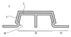
- the cross-sectional shape of the metal-resin composite is a hat shape, and the flange portion of the hat shape is an exposed portion 21. Since the flange portion where the metal plate is bent to the opposite side to the resin side at the boundary between the covering portion 22 and the exposed portion 21 is the exposed portion 21, the resin is less likely to leak to the flange portion (exposed portion) during molding. At the same time, it is easy to remove the excess resin that has leaked.
- the coating portion 22 is covered with another metal member 4 (inner metal) and welded, so that the resin portion can be visually recognized.
- the design of the metal-resin composite can be improved, and the strength of the metal-resin composite can be increased.
- the metal-resin composite preferably has a cross-sectional shape having a bent portion 26 at which the end of the exposed portion is bent. Since the end of the exposed portion 21 is bent, excess resin wraps around from one side surface to the other side surface of the metal plate 2 due to resin leakage as shown by the broken line arrow in FIG. 7 during molding. It is possible to prevent the metal plate from being held by the metal plate, and it is easy to grab the excess resin 28. By bending the resin 28 as shown by the thick line arrow in FIG. 7, it is easy to remove the excess resin 28 after molding.
- the direction in which the end of the exposed portion is bent may be either one main surface side of the metal plate or the other main surface side of the metal plate.
- the metal resin composite preferably has a thin resin thickness on the exposed portion side in the vicinity of the boundary between the coated portion and the exposed portion. Since the thickness of the resin near the boundary between the covering part and the exposed part is thin, as shown by the thick arrow in FIG. 8, when the excess resin leaked to the exposed part is bent, the extra resin is formed at the boundary. It is easy to break and the excess resin can be easily removed. In addition, during molding, the resin that flows and reaches the vicinity of the boundary is easily cooled and solidified, so that the resin that flows later can be dammed up and resin leakage can be reduced. The thickness of the resin at the boundary between the covering portion and the exposed portion can be adjusted by the mold.
- the thickness of the resin on the exposed portion side of the covering portion is covered as shown in FIG. 9, even if the notch shape 24 has a thin boundary only between the exposed portion and the covering portion. It may be gradually decreased toward the exposed portion near the boundary between the portion and the exposed portion.
- the metal-resin composite preferably has a protrusion 25 protruding toward the resin at the boundary between the covering portion and the exposed portion. At the time of molding, the protrusion 25 and the mold come into contact with each other to prevent resin leakage to the exposed portion 21.
- the metal-resin composite has a convex portion 27 in which the cross-sectional shape of the metal plate is curved between the covering portion 22 and the flange portion (exposed portion 21).
- the convex portion 27 is convex on the side opposite to the convex direction in the cross-sectional hat shape of the metal plate.
- the metal plate Since the metal plate has the above shape, the flange portion and the covering portion are separated from each other, making it difficult for excess resin to reach the flange portion. Further, during molding, even if the metal plate moves in the mold and floats up, it is prevented that a gap is generated between the mold and the metal plate, and resin leakage is suppressed. Further, even if a load is applied to the metal-resin composite, the stress is not concentrated in one place and is dispersed at the curved portion to improve the mechanical strength of the metal-resin composite.
- the metal-resin composite of the present invention can easily remove the excess resin even if the excess resin leaks to the exposed portion to which the resin is not desired to be applied during molding, and other metal members. Can be welded to.
Landscapes
- Engineering & Computer Science (AREA)
- Manufacturing & Machinery (AREA)
- Mechanical Engineering (AREA)
- Laminated Bodies (AREA)
- Injection Moulding Of Plastics Or The Like (AREA)
Priority Applications (2)
| Application Number | Priority Date | Filing Date | Title |
|---|---|---|---|
| PCT/IB2019/000671 WO2021005390A1 (ja) | 2019-07-05 | 2019-07-05 | 金属樹脂複合体及び該金属樹脂複合体の製造方法 |
| JP2021531198A JP7238989B2 (ja) | 2019-07-05 | 2019-07-05 | 金属樹脂複合体及び該金属樹脂複合体の製造方法 |
Applications Claiming Priority (1)
| Application Number | Priority Date | Filing Date | Title |
|---|---|---|---|
| PCT/IB2019/000671 WO2021005390A1 (ja) | 2019-07-05 | 2019-07-05 | 金属樹脂複合体及び該金属樹脂複合体の製造方法 |
Publications (1)
| Publication Number | Publication Date |
|---|---|
| WO2021005390A1 true WO2021005390A1 (ja) | 2021-01-14 |
Family
ID=74114406
Family Applications (1)
| Application Number | Title | Priority Date | Filing Date |
|---|---|---|---|
| PCT/IB2019/000671 Ceased WO2021005390A1 (ja) | 2019-07-05 | 2019-07-05 | 金属樹脂複合体及び該金属樹脂複合体の製造方法 |
Country Status (2)
| Country | Link |
|---|---|
| JP (1) | JP7238989B2 (https=) |
| WO (1) | WO2021005390A1 (https=) |
Cited By (1)
| Publication number | Priority date | Publication date | Assignee | Title |
|---|---|---|---|---|
| CN115696888A (zh) * | 2021-07-22 | 2023-02-03 | 启碁科技股份有限公司 | 屏蔽结构及其制造方法 |
Citations (4)
| Publication number | Priority date | Publication date | Assignee | Title |
|---|---|---|---|---|
| JP2003170531A (ja) * | 2001-12-10 | 2003-06-17 | Taisei Plas Co Ltd | 金属と樹脂の複合体及びその製造方法 |
| JP2007182071A (ja) * | 2005-12-08 | 2007-07-19 | Toray Ind Inc | アルミニウム合金と樹脂の複合体及びその製造方法 |
| JP2014004823A (ja) * | 2012-05-29 | 2014-01-16 | Polyplastics Co | 複合成形体の製造方法 |
| WO2016117711A1 (ja) * | 2015-01-23 | 2016-07-28 | 古河電気工業株式会社 | 金属部材と樹脂モールドとの複合体および樹脂モールドとの複合体形成用金属部材 |
-
2019
- 2019-07-05 WO PCT/IB2019/000671 patent/WO2021005390A1/ja not_active Ceased
- 2019-07-05 JP JP2021531198A patent/JP7238989B2/ja active Active
Patent Citations (4)
| Publication number | Priority date | Publication date | Assignee | Title |
|---|---|---|---|---|
| JP2003170531A (ja) * | 2001-12-10 | 2003-06-17 | Taisei Plas Co Ltd | 金属と樹脂の複合体及びその製造方法 |
| JP2007182071A (ja) * | 2005-12-08 | 2007-07-19 | Toray Ind Inc | アルミニウム合金と樹脂の複合体及びその製造方法 |
| JP2014004823A (ja) * | 2012-05-29 | 2014-01-16 | Polyplastics Co | 複合成形体の製造方法 |
| WO2016117711A1 (ja) * | 2015-01-23 | 2016-07-28 | 古河電気工業株式会社 | 金属部材と樹脂モールドとの複合体および樹脂モールドとの複合体形成用金属部材 |
Cited By (1)
| Publication number | Priority date | Publication date | Assignee | Title |
|---|---|---|---|---|
| CN115696888A (zh) * | 2021-07-22 | 2023-02-03 | 启碁科技股份有限公司 | 屏蔽结构及其制造方法 |
Also Published As
| Publication number | Publication date |
|---|---|
| JP7238989B2 (ja) | 2023-03-14 |
| JPWO2021005390A1 (https=) | 2021-01-14 |
Similar Documents
| Publication | Publication Date | Title |
|---|---|---|
| US6820678B2 (en) | Metal casting fabrication method | |
| WO2015034078A1 (ja) | 電子部品搭載基板およびその製造方法 | |
| JP2012245784A (ja) | 混成部材を製造するための方法ならびに製造する際に使用するためのカバー | |
| Huang et al. | Effect of interfacial nanostructures on shear strength of Al-PPS joints fabricated via injection moulding method combined with anodising | |
| TW201351437A (zh) | 晶片接合用導電性膏以及利用該導電性膏作晶片接合之方法 | |
| JP6226724B2 (ja) | 複合成形体の製造方法及び放熱性を向上させる方法 | |
| CN105378141B (zh) | 溅射靶材及其制造方法 | |
| JP2019181711A (ja) | 金属樹脂接合体 | |
| TWI762747B (zh) | 包覆材及其製造方法 | |
| CN114025932B (zh) | 金属树脂复合体的制造方法、该制造方法所使用的支承部件及金属树脂复合体 | |
| WO2021005390A1 (ja) | 金属樹脂複合体及び該金属樹脂複合体の製造方法 | |
| CN109183108B (zh) | 一种铝合金材料及其制备方法以及复合材料 | |
| CN109076116A (zh) | 一种电子设备壳体制备方法及电子设备壳体、电子设备 | |
| TWI418281B (zh) | 電子裝置殼體之製造方法 | |
| TW201200350A (en) | Composite of metal and plastic and method for making the same | |
| EP3805077B1 (en) | Automobile part | |
| JP6625774B1 (ja) | 中空パッケージ構造およびその製造方法、ならびに半導体装置およびその製造方法 | |
| KR102102755B1 (ko) | 관통 구멍의 밀봉 구조 및 밀봉 방법, 그리고 관통 구멍을 밀봉하기 위한 전사 기판 | |
| TWI549809B (zh) | 鋁或鋁合金與塑膠的複合體及其製作方法 | |
| JP7498588B2 (ja) | 金属樹脂複合体 | |
| KR20160124304A (ko) | 알루미늄 전선용 단자 및 그 제조방법 | |
| JPH0623775A (ja) | 圧縮成形方法 | |
| CN117116774A (zh) | 一种引线框架及其制备方法 | |
| CN114103351A (zh) | 一种铝塑膜、制备方法和包含其的电池 | |
| JP2019005927A (ja) | 積層アルミニウム合金及びその製造方法、並びに積層体 |
Legal Events
| Date | Code | Title | Description |
|---|---|---|---|
| 121 | Ep: the epo has been informed by wipo that ep was designated in this application |
Ref document number: 19934394 Country of ref document: EP Kind code of ref document: A1 |
|
| ENP | Entry into the national phase |
Ref document number: 2021531198 Country of ref document: JP Kind code of ref document: A |
|
| NENP | Non-entry into the national phase |
Ref country code: DE |
|
| 122 | Ep: pct application non-entry in european phase |
Ref document number: 19934394 Country of ref document: EP Kind code of ref document: A1 |