WO2020262318A1 - 管継手 - Google Patents
管継手 Download PDFInfo
- Publication number
- WO2020262318A1 WO2020262318A1 PCT/JP2020/024445 JP2020024445W WO2020262318A1 WO 2020262318 A1 WO2020262318 A1 WO 2020262318A1 JP 2020024445 W JP2020024445 W JP 2020024445W WO 2020262318 A1 WO2020262318 A1 WO 2020262318A1
- Authority
- WO
- WIPO (PCT)
- Prior art keywords
- pipe
- tip
- tooth
- peripheral surface
- outer peripheral
- Prior art date
Links
- 230000002093 peripheral effect Effects 0.000 claims description 278
- 238000003466 welding Methods 0.000 claims description 81
- 238000007789 sealing Methods 0.000 claims description 67
- 230000009467 reduction Effects 0.000 claims description 45
- 238000003780 insertion Methods 0.000 claims description 31
- 230000037431 insertion Effects 0.000 claims description 31
- 238000003860 storage Methods 0.000 claims description 26
- 230000002265 prevention Effects 0.000 claims description 24
- 238000003825 pressing Methods 0.000 claims description 23
- 239000003566 sealing material Substances 0.000 claims description 18
- 238000005452 bending Methods 0.000 claims description 11
- 239000002184 metal Substances 0.000 abstract description 21
- 229910052751 metal Inorganic materials 0.000 abstract description 21
- 239000003507 refrigerant Substances 0.000 description 14
- 230000009471 action Effects 0.000 description 13
- 238000012545 processing Methods 0.000 description 11
- 239000012530 fluid Substances 0.000 description 10
- 238000000034 method Methods 0.000 description 10
- 230000036544 posture Effects 0.000 description 10
- 230000008569 process Effects 0.000 description 10
- 210000000078 claw Anatomy 0.000 description 9
- 239000000463 material Substances 0.000 description 9
- 229910001369 Brass Inorganic materials 0.000 description 8
- 239000010951 brass Substances 0.000 description 8
- 230000008901 benefit Effects 0.000 description 6
- 239000010949 copper Substances 0.000 description 6
- 230000033001 locomotion Effects 0.000 description 6
- 230000002411 adverse Effects 0.000 description 4
- 230000007704 transition Effects 0.000 description 4
- 229910052782 aluminium Inorganic materials 0.000 description 3
- XAGFODPZIPBFFR-UHFFFAOYSA-N aluminium Chemical compound [Al] XAGFODPZIPBFFR-UHFFFAOYSA-N 0.000 description 3
- 238000005520 cutting process Methods 0.000 description 3
- 230000000694 effects Effects 0.000 description 3
- 230000000149 penetrating effect Effects 0.000 description 3
- RYGMFSIKBFXOCR-UHFFFAOYSA-N Copper Chemical compound [Cu] RYGMFSIKBFXOCR-UHFFFAOYSA-N 0.000 description 2
- 238000013459 approach Methods 0.000 description 2
- 230000000903 blocking effect Effects 0.000 description 2
- 238000010276 construction Methods 0.000 description 2
- 229910052802 copper Inorganic materials 0.000 description 2
- 238000005260 corrosion Methods 0.000 description 2
- 230000007797 corrosion Effects 0.000 description 2
- 238000013461 design Methods 0.000 description 2
- 238000002474 experimental method Methods 0.000 description 2
- 239000007769 metal material Substances 0.000 description 2
- 150000002739 metals Chemical class 0.000 description 2
- 230000004048 modification Effects 0.000 description 2
- 238000012986 modification Methods 0.000 description 2
- 239000004033 plastic Substances 0.000 description 2
- 230000001105 regulatory effect Effects 0.000 description 2
- 230000000295 complement effect Effects 0.000 description 1
- 239000000470 constituent Substances 0.000 description 1
- 238000005336 cracking Methods 0.000 description 1
- 230000009545 invasion Effects 0.000 description 1
- 235000013372 meat Nutrition 0.000 description 1
Images


Classifications
-
- F—MECHANICAL ENGINEERING; LIGHTING; HEATING; WEAPONS; BLASTING
- F16—ENGINEERING ELEMENTS AND UNITS; GENERAL MEASURES FOR PRODUCING AND MAINTAINING EFFECTIVE FUNCTIONING OF MACHINES OR INSTALLATIONS; THERMAL INSULATION IN GENERAL
- F16L—PIPES; JOINTS OR FITTINGS FOR PIPES; SUPPORTS FOR PIPES, CABLES OR PROTECTIVE TUBING; MEANS FOR THERMAL INSULATION IN GENERAL
- F16L19/00—Joints in which sealing surfaces are pressed together by means of a member, e.g. a swivel nut, screwed on or into one of the joint parts
- F16L19/02—Pipe ends provided with collars or flanges, integral with the pipe or not, pressed together by a screwed member
- F16L19/0212—Pipe ends provided with collars or flanges, integral with the pipe or not, pressed together by a screwed member using specially adapted sealing means
- F16L19/0218—Pipe ends provided with collars or flanges, integral with the pipe or not, pressed together by a screwed member using specially adapted sealing means comprising only sealing rings
-
- F—MECHANICAL ENGINEERING; LIGHTING; HEATING; WEAPONS; BLASTING
- F16—ENGINEERING ELEMENTS AND UNITS; GENERAL MEASURES FOR PRODUCING AND MAINTAINING EFFECTIVE FUNCTIONING OF MACHINES OR INSTALLATIONS; THERMAL INSULATION IN GENERAL
- F16L—PIPES; JOINTS OR FITTINGS FOR PIPES; SUPPORTS FOR PIPES, CABLES OR PROTECTIVE TUBING; MEANS FOR THERMAL INSULATION IN GENERAL
- F16L19/00—Joints in which sealing surfaces are pressed together by means of a member, e.g. a swivel nut, screwed on or into one of the joint parts
- F16L19/02—Pipe ends provided with collars or flanges, integral with the pipe or not, pressed together by a screwed member
- F16L19/0206—Pipe ends provided with collars or flanges, integral with the pipe or not, pressed together by a screwed member the collar not being integral with the pipe
-
- F—MECHANICAL ENGINEERING; LIGHTING; HEATING; WEAPONS; BLASTING
- F16—ENGINEERING ELEMENTS AND UNITS; GENERAL MEASURES FOR PRODUCING AND MAINTAINING EFFECTIVE FUNCTIONING OF MACHINES OR INSTALLATIONS; THERMAL INSULATION IN GENERAL
- F16L—PIPES; JOINTS OR FITTINGS FOR PIPES; SUPPORTS FOR PIPES, CABLES OR PROTECTIVE TUBING; MEANS FOR THERMAL INSULATION IN GENERAL
- F16L19/00—Joints in which sealing surfaces are pressed together by means of a member, e.g. a swivel nut, screwed on or into one of the joint parts
- F16L19/02—Pipe ends provided with collars or flanges, integral with the pipe or not, pressed together by a screwed member
- F16L19/0237—Pipe ends provided with collars or flanges, integral with the pipe or not, pressed together by a screwed member specially adapted for use with attachments, e.g. reduction units, T-pieces, bends or the like
-
- F—MECHANICAL ENGINEERING; LIGHTING; HEATING; WEAPONS; BLASTING
- F16—ENGINEERING ELEMENTS AND UNITS; GENERAL MEASURES FOR PRODUCING AND MAINTAINING EFFECTIVE FUNCTIONING OF MACHINES OR INSTALLATIONS; THERMAL INSULATION IN GENERAL
- F16L—PIPES; JOINTS OR FITTINGS FOR PIPES; SUPPORTS FOR PIPES, CABLES OR PROTECTIVE TUBING; MEANS FOR THERMAL INSULATION IN GENERAL
- F16L19/00—Joints in which sealing surfaces are pressed together by means of a member, e.g. a swivel nut, screwed on or into one of the joint parts
- F16L19/04—Joints in which sealing surfaces are pressed together by means of a member, e.g. a swivel nut, screwed on or into one of the joint parts using additional rigid rings, sealing directly on at least one pipe end, which is flared either before or during the making of the connection
-
- F—MECHANICAL ENGINEERING; LIGHTING; HEATING; WEAPONS; BLASTING
- F16—ENGINEERING ELEMENTS AND UNITS; GENERAL MEASURES FOR PRODUCING AND MAINTAINING EFFECTIVE FUNCTIONING OF MACHINES OR INSTALLATIONS; THERMAL INSULATION IN GENERAL
- F16L—PIPES; JOINTS OR FITTINGS FOR PIPES; SUPPORTS FOR PIPES, CABLES OR PROTECTIVE TUBING; MEANS FOR THERMAL INSULATION IN GENERAL
- F16L19/00—Joints in which sealing surfaces are pressed together by means of a member, e.g. a swivel nut, screwed on or into one of the joint parts
- F16L19/06—Joints in which sealing surfaces are pressed together by means of a member, e.g. a swivel nut, screwed on or into one of the joint parts in which radial clamping is obtained by wedging action on non-deformed pipe ends
- F16L19/065—Joints in which sealing surfaces are pressed together by means of a member, e.g. a swivel nut, screwed on or into one of the joint parts in which radial clamping is obtained by wedging action on non-deformed pipe ends the wedging action being effected by means of a ring
-
- F—MECHANICAL ENGINEERING; LIGHTING; HEATING; WEAPONS; BLASTING
- F16—ENGINEERING ELEMENTS AND UNITS; GENERAL MEASURES FOR PRODUCING AND MAINTAINING EFFECTIVE FUNCTIONING OF MACHINES OR INSTALLATIONS; THERMAL INSULATION IN GENERAL
- F16L—PIPES; JOINTS OR FITTINGS FOR PIPES; SUPPORTS FOR PIPES, CABLES OR PROTECTIVE TUBING; MEANS FOR THERMAL INSULATION IN GENERAL
- F16L19/00—Joints in which sealing surfaces are pressed together by means of a member, e.g. a swivel nut, screwed on or into one of the joint parts
- F16L19/06—Joints in which sealing surfaces are pressed together by means of a member, e.g. a swivel nut, screwed on or into one of the joint parts in which radial clamping is obtained by wedging action on non-deformed pipe ends
- F16L19/075—Joints in which sealing surfaces are pressed together by means of a member, e.g. a swivel nut, screwed on or into one of the joint parts in which radial clamping is obtained by wedging action on non-deformed pipe ends specially adapted for spigot-and-socket joints for pipes of the same diameter
-
- F—MECHANICAL ENGINEERING; LIGHTING; HEATING; WEAPONS; BLASTING
- F16—ENGINEERING ELEMENTS AND UNITS; GENERAL MEASURES FOR PRODUCING AND MAINTAINING EFFECTIVE FUNCTIONING OF MACHINES OR INSTALLATIONS; THERMAL INSULATION IN GENERAL
- F16L—PIPES; JOINTS OR FITTINGS FOR PIPES; SUPPORTS FOR PIPES, CABLES OR PROTECTIVE TUBING; MEANS FOR THERMAL INSULATION IN GENERAL
- F16L19/00—Joints in which sealing surfaces are pressed together by means of a member, e.g. a swivel nut, screwed on or into one of the joint parts
- F16L19/08—Joints in which sealing surfaces are pressed together by means of a member, e.g. a swivel nut, screwed on or into one of the joint parts with metal rings which bite into the wall of the pipe
- F16L19/10—Joints in which sealing surfaces are pressed together by means of a member, e.g. a swivel nut, screwed on or into one of the joint parts with metal rings which bite into the wall of the pipe the profile of the ring being altered
- F16L19/106—Joints in which sealing surfaces are pressed together by means of a member, e.g. a swivel nut, screwed on or into one of the joint parts with metal rings which bite into the wall of the pipe the profile of the ring being altered the ring comprising a shoulder against which the pipe end abuts
-
- F—MECHANICAL ENGINEERING; LIGHTING; HEATING; WEAPONS; BLASTING
- F16—ENGINEERING ELEMENTS AND UNITS; GENERAL MEASURES FOR PRODUCING AND MAINTAINING EFFECTIVE FUNCTIONING OF MACHINES OR INSTALLATIONS; THERMAL INSULATION IN GENERAL
- F16L—PIPES; JOINTS OR FITTINGS FOR PIPES; SUPPORTS FOR PIPES, CABLES OR PROTECTIVE TUBING; MEANS FOR THERMAL INSULATION IN GENERAL
- F16L19/00—Joints in which sealing surfaces are pressed together by means of a member, e.g. a swivel nut, screwed on or into one of the joint parts
- F16L19/08—Joints in which sealing surfaces are pressed together by means of a member, e.g. a swivel nut, screwed on or into one of the joint parts with metal rings which bite into the wall of the pipe
- F16L19/10—Joints in which sealing surfaces are pressed together by means of a member, e.g. a swivel nut, screwed on or into one of the joint parts with metal rings which bite into the wall of the pipe the profile of the ring being altered
- F16L19/12—Joints in which sealing surfaces are pressed together by means of a member, e.g. a swivel nut, screwed on or into one of the joint parts with metal rings which bite into the wall of the pipe the profile of the ring being altered with additional sealing means
-
- F—MECHANICAL ENGINEERING; LIGHTING; HEATING; WEAPONS; BLASTING
- F16—ENGINEERING ELEMENTS AND UNITS; GENERAL MEASURES FOR PRODUCING AND MAINTAINING EFFECTIVE FUNCTIONING OF MACHINES OR INSTALLATIONS; THERMAL INSULATION IN GENERAL
- F16L—PIPES; JOINTS OR FITTINGS FOR PIPES; SUPPORTS FOR PIPES, CABLES OR PROTECTIVE TUBING; MEANS FOR THERMAL INSULATION IN GENERAL
- F16L19/00—Joints in which sealing surfaces are pressed together by means of a member, e.g. a swivel nut, screwed on or into one of the joint parts
- F16L19/08—Joints in which sealing surfaces are pressed together by means of a member, e.g. a swivel nut, screwed on or into one of the joint parts with metal rings which bite into the wall of the pipe
- F16L19/10—Joints in which sealing surfaces are pressed together by means of a member, e.g. a swivel nut, screwed on or into one of the joint parts with metal rings which bite into the wall of the pipe the profile of the ring being altered
- F16L19/14—Joints in which sealing surfaces are pressed together by means of a member, e.g. a swivel nut, screwed on or into one of the joint parts with metal rings which bite into the wall of the pipe the profile of the ring being altered the rings being integral with one of the connecting parts
-
- F—MECHANICAL ENGINEERING; LIGHTING; HEATING; WEAPONS; BLASTING
- F16—ENGINEERING ELEMENTS AND UNITS; GENERAL MEASURES FOR PRODUCING AND MAINTAINING EFFECTIVE FUNCTIONING OF MACHINES OR INSTALLATIONS; THERMAL INSULATION IN GENERAL
- F16L—PIPES; JOINTS OR FITTINGS FOR PIPES; SUPPORTS FOR PIPES, CABLES OR PROTECTIVE TUBING; MEANS FOR THERMAL INSULATION IN GENERAL
- F16L21/00—Joints with sleeve or socket
- F16L21/02—Joints with sleeve or socket with elastic sealing rings between pipe and sleeve or between pipe and socket, e.g. with rolling or other prefabricated profiled rings
- F16L21/04—Joints with sleeve or socket with elastic sealing rings between pipe and sleeve or between pipe and socket, e.g. with rolling or other prefabricated profiled rings in which sealing rings are compressed by axially-movable members
Definitions
- the present invention relates to pipe fittings.
- Flare fittings are widely known as a type of pipe fittings.
- the flared joint is formed by plastically processing a flared portion f at the end of the pipe p with a special jig, and the flared portion f is formed on the flared joint main body h. It is configured to be applied to the tapered portion a and tightened with the bag nut n, sandwiched between the tapered surface t of the bag nut n and the tapered portion a of the flare joint body h, and the sealing property is ensured by mutual pressure welding of the metal surfaces. (See, for example, Patent Document 1).
- Patent Document 1 See, for example, Patent Document 1
- Patent Document 2 a pipe joint having a structure as shown in FIG. 50 is proposed (see Patent Document 2).
- the bag nut 54 is screwed to the flare joint main body 51 having the male threaded portion 52 and the tapered portion 53, but the internal storage space portion 55 is fitted with a bag nut 54.
- the stop ring 56 has a sealing groove 57, an O-ring 58 is incorporated therein, and a sealing action with the pipe P to be inserted is performed by the O-ring 58.
- the stop ring 56 has a pressure contact gradient surface 59 that presses against the tapered portion 53 of the joint body 51.
- a thin-walled cylindrical portion 60 is extended on the tip side with the same diameter, and a claw portion 61 for biting into the outer peripheral surface of the pipe having a triangular cross section is attached to the tip end of the thin-walled cylindrical portion 60.
- the claw portion 61 is configured to bite into the outer peripheral surface of the pipe P as the bag nut 54 is screwed (see Patent Document 2).
- Patent Document 2 In order to actually provide the pipe joint shown in FIG. 50 (Patent Document 2) to the market for refrigerant piping, the following three points are unsolved or technically insufficient. However, it has become clear. (i) As the bag nut 54 is screwed, the stop ring 56 co-rotates and causes a relative slip between the tapered portion 53 and the pressure contact slope surface 59, which breaks the metal pressure contact seal. Slip. In order to prevent this, it is necessary to perform "preliminary processing" in which the claw portion 61 is made to bite into the outer peripheral surface of the pipe P in advance by using a special jig. Such "preliminary processing" significantly reduces work efficiency at the pipe connection site.
- the wall thickness of the actual pipe P is about the same as the wall thickness of the thin cylindrical portion 60, and may be about 1/3 of the wall thickness Tp shown in FIG. 50. Therefore, even the claw portion 61 having a triangular cross section does not bite into the surface of the Cu pipe P, but only locally plastically deforms the pipe P in the inner diameter direction, and the pipe pull-out resistance is small.
- the claw portion 61 does not bite into the pipe P, and after the piping work is completed, when an external force that rotates the pipe P around its axis acts, the pipe P is easily rotated. Along with this, the metal sealing property between the claw portion 61 and the outer peripheral surface of the pipe is destroyed. Therefore, the O-ring 58 cannot be omitted.
- the present invention has a flare joint body having a male screw portion and a tip diameter reduction gradient surface, and a female screw portion screwed to the male screw portion at the base end of the hole portion, and the hole portion has the same.
- a bag nut having a storage space having the same diameter, a stepped portion, and a tapered tip diameter, and a base end that is installed in the storage space and press-contacts with the tip diameter-reduced slope surface.
- the above-mentioned tooth in a pipe joint provided with a stop ring having a lateral pressure contact gradient surface and a thin-walled substantially cylindrical portion that can be plastically deformable on the tip side and a tooth portion for preventing pipe withdrawal at the tip head thereof.
- the portion is composed of rear teeth and anterior teeth arranged at minute intervals, and the cross-sectional shape of the posterior teeth is a trapezoidal to substantially trapezoidal shape having a linear first tip side as an upper side, and the cross-sectional shape of the anterior teeth is , A trapezoidal or substantially trapezoidal shape having a linear second tip side as an upper side, with respect to the outer peripheral surface of the straight tip portion of the connected pipe, the first tip side of the rear tooth of the stop ring and the first tip side of the front tooth. 2
- the tip side is configured to be in a strong pressure contact state with the screwing of the bag nut to generate a pipe pull-out resistance force.
- the rear teeth and the front teeth of the tooth portion are strongly pressed against the outer peripheral surface as the bag nut is screwed, and the rear teeth and the front teeth exert a sealing function to the inner peripheral surface of the stop ring.
- the sealing material is omitted on the outer peripheral surface.
- the tip reduced diameter tapered portion is composed of a proximal end side steep slope tapered portion and a tip end side gentle gradient tapered portion.
- the rear teeth and the front teeth are configured to share the pipe pull-out resistance force substantially equal to the outer peripheral surface of the pipe in the strong pressure contact state.
- the first tip side of the rear tooth and the second tip side of the front tooth are parallel to each other, and the first tip side is from the second tip side.
- the second tip side protrudes in the radial inward direction from the first tip side, or the second tip side and the first tip end.
- the inclination angle of the tip side of the tip reduced diameter tapered portion and the shape and dimensions of the tip head were set so that the sides were at the same position in the radial direction.
- the thin-walled substantially cylindrical portion having the rear teeth and the anterior teeth at the tips is formed into a conical cylinder having a diameter widening in the tip direction.
- a small protrusion for preventing the thin-walled substantially cylindrical portion from being deformed due to excessive diameter expansion is provided on the outer peripheral surface of the thin-walled substantially cylindrical portion, and the small protrusion is attached to the bag nut. It was configured to come into contact with the inner surface of the hole.
- the base of the stop ring is an annular small ridge that is hooked from the inner diameter side to the annular tip edge portion formed by the tip of the tip diameter-reduced gradient surface of the joint body and the hole portion of the joint body. It is attached to the inner peripheral edge of the end side pressure contact slope surface, and is configured to prevent the base end portion of the stop ring from being excessively deformed to the radial outward side.
- At least the inner portion of the pipe insertion hole of the stop ring is formed in a tapered shape with a reduced diameter in the inner diameter, and the straight tip is pressed against the inner peripheral surface of the pipe insertion hole when the pipe insertion is completed. did.
- the tooth portion for preventing pulling out which is in a strong pressure contact state with respect to the outer peripheral surface of the connected pipe and generates a pipe pulling resistance force
- the joint body itself has one.
- the pull-out prevention tooth portion that generates a pipe pull-out resistance force by being strongly pressed against the outer peripheral surface of the connected pipe is provided.
- the joint body itself has it integrally; the pull-out prevention tooth portion is formed at the tip of a thin-walled substantially cylindrical portion protruding at the tip of the joint body; the pull-out prevention tooth portion is arranged at a minute interval.
- the cross-sectional shape of the rear tooth is a trapezoidal or substantially trapezoidal shape having a linear first tip side as an upper side
- the cross-sectional shape of the front tooth is a linear second tip side as an upper side.
- the first tip side of the rear tooth and the second tip side of the front tooth of the joint body are accompanied by the screwing of the cap nut. Therefore, it is configured to be in a strong pressure welding state and generate a pipe pull-out resistance force.
- the bag nut has a female threaded portion screwed to the male threaded portion of the joint body at the base end of the hole, and a stepped portion and a tip diameter taper in the middle of the hole.
- the tip-reduced taper portion is configured to have a base end-side steep slope taper portion and a tip-end side gentle slope taper portion.
- the rear teeth and the front teeth are configured to share the pipe pull-out resistance force substantially equal to the outer peripheral surface of the pipe in the strong pressure contact state.
- the first tip side of the rear tooth and the second tip side of the front tooth are parallel to each other, and the first tip side is the second tip.
- the second tip side protrudes in the radial inward direction from the first tip side, or the second tip side and the second tip side 1
- the tip side is set to the same position in the radial direction; the inclination angle of the tip side of the tip reduced diameter tapered portion and the shape and dimension of the tip head are set.
- the thin-walled substantially cylindrical portion having the rear teeth and the anterior teeth at the tips is formed into a conical cylinder having a diameter widening in the tip direction.
- a small protrusion for preventing the thin-walled substantially cylindrical portion from being deformed due to excessive diameter expansion is provided on the outer peripheral surface of the thin-walled substantially cylindrical portion, and the small protrusion is attached to the bag nut. It was configured to come into contact with the inner surface of the hole.
- the inner portion of the pipe insertion hole portion of the joint body is formed in a tapered shape with a reduced diameter in the inner diameter, and the outer peripheral surface of the pipe is pressed against the inner peripheral surface of the pipe insertion hole portion in the state where the pipe insertion is completed.
- the present invention has a male screw portion and a flare joint body having a tip diameter reduction gradient surface; a female screw portion screwed to the male screw portion is provided at the base end of the hole portion, and the hole portion has a female screw portion.
- a bag nut that forms a storage space portion having the same diameter portion, a stepped portion, and a tip diameter reduction taper portion; the base end that is installed in the storage space portion and is pressed against the tip diameter reduction gradient surface.
- a stop ring having a lateral pressure contact gradient surface and having a plastically deformable thin-walled substantially cylindrical portion and a tooth portion for preventing pipe withdrawal at the tip head of the pipe joint;
- the portion is composed of rear teeth and anterior teeth arranged at a minute interval; with respect to the outer peripheral surface of the straight tip portion of the connected pipe, the first tip side of the posterior tooth of the stop ring and the anterior tooth.
- the second tip side is configured to be in a strong pressure contact state with the screwing of the bag nut to generate a pipe pull-out resistance force;
- the stop ring has a basic inner diameter part into which the pipe is inserted and a bag.
- the present invention has a male screw portion and a flare joint body having a tip diameter reduction gradient surface; a female screw portion screwed to the male screw portion is provided at the base end of the hole portion, and the hole portion has a female screw portion.
- a bag nut that forms a storage space with the same diameter, stepped portion, and tip diameter reduction taper; the base end that is installed in the storage space and presses against the tip diameter reduction gradient surface.
- a pipe joint having a lateral pressure contact gradient surface and a stop ring having a plastically deformable thin-walled substantially cylindrical portion and a tooth portion for preventing pipe withdrawal at the tip head thereof;
- the portion is composed of rear teeth and anterior teeth arranged at minute intervals;
- the cross-sectional shape of the rear teeth is substantially trapezoidal, and the first tip side composed of the upper side of the substantially trapezoidal shape is It has a short rear half and a tall front half via a rounded intermediate step;
- the cross-sectional shape of the front teeth is substantially trapezoidal, and from the upper side of the substantially trapezoidal shape.
- the second tip side thereof is a bent line having a short rear half side portion and a tall front half portion through a slope surface inclined backward and downward.
- the first tip side of the rear tooth and the second tip side of the front tooth of the stop ring are strengthened as the cap nut is screwed. It is configured to generate a pipe pull-out resistance force in a pressure contact state, and further, in the strong pressure contact state, the first tip side of the rear tooth and the second tip side of the front tooth are on the outer peripheral surface of the pipe. On the other hand, it was configured to perform a double seal function by pressure contacting in a biting shape. Further, with respect to the outer peripheral surface of the straight tip portion of the connected pipe, the first tip side of the rear tooth and the second tip side of the front tooth of the stop ring become strong as the cap nut is screwed.
- the first tip side of the rear tooth and the second tip side of the front tooth are pressed against the outer peripheral surface of the pipe in a biting manner to form a double seal function. Due to the double sealing function, the sealing material is omitted on the inner and outer peripheral surfaces of the stop ring.
- the front half side portion of the first tip side of the rear tooth has a closed annular small concave peripheral groove on the outer peripheral surface of the pipe. It bites into the pipe so as to form it, prevents spiral rotation of the pipe, and further, the rounded intermediate step portion of the first tip side presses against the rear side surface of the small concave peripheral groove to exert a sealing function.
- the rear teeth and the front teeth share the outer peripheral surface of the pipe so that the pipe pull-out resistance of the front teeth becomes larger than the pipe pull-out resistance of the rear teeth in the strong pressure contact state;
- the front teeth share the function of preventing the pipe from pulling out by strongly pressing the second tip side of the pipe against the outer peripheral surface in the shape of a bent line to prevent the pipe from coming out due to an external force in the bending direction.
- the rear teeth and the front teeth are the same with respect to the outer peripheral surface of the pipe so that the first tip side and the second tip side are equidistant from the axial center of the pipe. It was configured to bite into the depth.
- the tip reduced diameter tapered portion is composed of a proximal end side steep slope tapered portion and an intermediate gentle gradient tapered portion, and an intermediate steep slope tapered portion and a tip side gentle gradient tapered portion.
- the tip reduced diameter tapered portion is composed of a proximal end side steep slope tapered portion and an intermediate gentle gradient tapered portion, and an intermediate steep slope tapered portion and a tip side gentle gradient tapered portion.
- the tip head of the thin-walled substantially cylindrical portion is formed on the outer periphery of the tip head at the first convex portion composed of the most advanced outer peripheral corner portion and the axial position corresponding to the axial position of the rear tooth.
- the second convex portion has a low triangular hill-shaped second convex portion that has been formed; when the tip head of the tip head slides into the tip diameter-reduced tapered portion as the bag nut is screwed, the second convex portion is formed.
- the portion is pressed in the radial inward direction by the base end side steep slope tapered portion to perform the first pushing step of pressing the rear teeth against the outer peripheral surface of the pipe, and then the first convex portion is subjected to the intermediate steep slope. It is configured to perform the second pushing step of pressing the front teeth against the outer peripheral surface of the pipe by being pressed in the radial inward direction by the tapered portion.
- the stepped portion formed by the tip surface of the basic short cylindrical portion of the stop ring and the stepped portion of the hole portion of the bag nut come into contact with each other.
- the operator can detect an increase in the screwing resistance of the bag nut.
- a support in-core that supports the tip of the pipe from the inner peripheral side is attached so that the rear teeth and the front teeth of the stop ring are in the strong pressure contact state with respect to the outer peripheral surface of the pipe.
- the cap nut as the cap nut is screwed into the male threaded portion of the joint body, it is in a strong pressure contact state with respect to the outer peripheral surface of the connected pipe, and a pull-out prevention tooth that generates a pipe pull-out resistance force.
- the pull-out prevention tooth is provided at the tip of a thin-walled substantially cylindrical portion that is integrally provided with the joint body itself and has a male screw portion on the outer periphery and is continuously provided in a protruding shape from the tip surface of the connection cylinder portion. A portion is formed; the tooth portion is composed of rear teeth and anterior teeth arranged at minute intervals; the average wall thickness dimension of the thin-walled substantially cylindrical portion is T 35, and the average wall thickness of the connecting cylinder portion is defined. Assuming that the thickness dimension is T 7 , the relational expression of 0.40 ⁇ T 7 ⁇ T 35 ⁇ 0.75 ⁇ T 7 holds.
- the cap nut as the cap nut is screwed into the male threaded portion of the joint body, it is in a strong pressure contact state with respect to the outer peripheral surface of the connected pipe, and a pull-out prevention tooth that generates a pipe pull-out resistance force.
- the pull-out prevention tooth is provided at the tip of a thin-walled substantially cylindrical portion that is integrally provided with the joint body itself and has a male screw portion on the outer periphery and is continuously provided in a protruding shape from the tip surface of the connection cylinder portion. A portion is formed; the tooth portion is composed of rear teeth and anterior teeth arranged at minute intervals; the cross-sectional shape of the rear teeth is substantially trapezoidal, and from the upper side of the substantially trapezoidal shape.
- the first tip side thereof has a short rear half side portion and a tall front half side portion via a rounded intermediate step portion; the cross-sectional shape of the front teeth is substantially trapezoidal, and moreover.
- the second tip side formed of the upper side of the substantially trapezoidal shape is a bent line having a short second half side portion and a tall front half side portion via a slope surface inclined backward and downward.
- the first tip side of the rear tooth and the second tip side of the front tooth of the joint body become strong as the cap nut is screwed. It is configured to generate a pipe pull-out resistance force in a pressure contact state, and further, in the strong pressure contact state, the first tip side of the rear tooth and the second tip side of the front tooth are on the outer peripheral surface of the pipe. On the other hand, it was configured to perform a double seal function by pressure contacting in a biting shape. Further, with respect to the outer peripheral surface of the straight tip portion of the connected pipe, the first tip side of the rear tooth and the second tip side of the front tooth of the joint body become strong as the cap nut is screwed.
- the first tip side of the rear tooth and the second tip side of the front tooth are pressed against the outer peripheral surface of the pipe in a biting manner to form a double seal function.
- the sealing material is omitted on the inner and outer peripheral surfaces of the joint body.
- the front half portion of the first tip side of the rear tooth has a closed annular small concave peripheral groove on the outer peripheral surface of the pipe. It bites into the pipe so as to form it, prevents spiral rotation of the pipe, and further, the rounded intermediate step portion of the first tip side presses against the rear side surface of the small concave peripheral groove to exert a sealing function.
- the rear teeth and the front teeth share the outer peripheral surface of the pipe so that the pipe pull-out resistance of the front teeth becomes larger than the pipe pull-out resistance of the rear teeth in the strong pressure contact state;
- the front teeth share the function of preventing the pipe from pulling out by strongly pressing the second tip side of the pipe against the outer peripheral surface in the shape of a bent line to prevent the pipe from coming out due to an external force in the bending direction.
- the rear teeth and the front teeth are the same with respect to the outer peripheral surface of the pipe so that the first tip side and the second tip side are equidistant from the axial center of the pipe. It was configured to bite into the depth.
- the tip reduced diameter tapered portion is composed of a proximal end side steep slope tapered portion and an intermediate gentle gradient tapered portion, and an intermediate steep slope tapered portion and a tip side gentle gradient tapered portion.
- the tip reduced diameter tapered portion is composed of a proximal end side steep slope tapered portion and an intermediate gentle gradient tapered portion, and an intermediate steep slope tapered portion and a tip side gentle gradient tapered portion.
- the tip head of the thin-walled substantially cylindrical portion is formed on the outer periphery of the tip head at the first convex portion composed of the tip outer peripheral corner portion and the axial position corresponding to the axial position of the rear tooth. It has a low triangular hill-shaped second convex portion that has been formed; when the tip head of the tip head slides into the tip diameter-reduced tapered portion as the bag nut is screwed, the second convex portion is formed.
- the portion is pressed in the radial inward direction by the base end side steep slope tapered portion to perform the first pushing step of pressing the rear teeth against the outer peripheral surface of the pipe, and then the first convex portion is subjected to the intermediate steep slope. It is configured to perform the second pushing step of pressing the front teeth against the outer peripheral surface of the pipe by being pressed in the radial inward direction by the tapered portion.
- a support in-core is provided to support the tip of the pipe from the inner peripheral side in the strong pressure contact state between the rear teeth and the front teeth of the joint body with respect to the outer peripheral surface of the pipe.
- the two rear teeth and the front teeth are in a strong pressure contact state with respect to the outer peripheral surface of the pipe, the pipe pull-out resistance is large, and excellent sealing performance (sealing property) against a refrigerant or the like is exhibited.
- the "preliminary processing" described in the above-mentioned problem (i) can be omitted, and the pipe connection work can be performed quickly and efficiently.
- the rear and front teeth each exert their own functions (actions) and complement each other, they have excellent overall sealing performance (sealing properties) and pull-out resistance when bending force acts on the pipe. It demonstrates its properties and can reliably prevent accidents in which the pipe is pulled out.
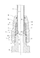
- Explanatory drawing showing a strong pressure welding state (A) is an explanatory view of an enlarged cross section of a main part, (B) is an explanatory view of a partially non-cross section showing the main part of (A) further enlarged, (C). Is an explanatory view of a partial non-cross section showing the main part of (A) in a further enlarged manner. It is a figure which shows another Example, (A) is the expanded sectional view of the main part (the tip head) in the initial set state, (B) is the enlarged sectional view of the main part which shows the strong pressure welding state. It is sectional drawing which showed the 4th Embodiment of this invention and showed the state in the process of pipe connection work.
- sectional drawing which shows the pipe connection completion state. It is sectional drawing which shows an example of a bag nut, (A) is an overall sectional view, (B) is an enlarged sectional view of a main part. It is sectional drawing of one Example of a joint body. It is an enlarged sectional view of the main part of a joint body. It is an enlarged cross-sectional explanatory view of the main part which shows the initial set state of the tip head. It is an enlarged cross-sectional explanatory view of the main part for sequentially explaining the operation of the tip head. It is an enlarged cross-sectional explanatory view of the main part for sequentially explaining the operation of the tip head.
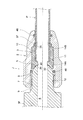
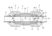
- the pipe joint J includes a flare joint main body 1F, a bag nut 2, and a stop ring 3, and is further connected.
- the tip of the pipe P has a straight tip 10 (without the conventional flaring process).
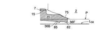
- the flare joint body 1F has been used for a long time, is similar to the flare joint body h shown in FIG. 49, and has a tip diameter reduction gradient surface 5. That is, the tip diameter reduction gradient surface 5 is formed at the tip of the connection cylinder portion 7 through which the flow path hole 6 is formed.
- the overall shape can be straight, T-shaped, Y-shaped, cross-shaped, etc., but the shapes of other connecting ends existing outside the drawings of FIGS. 1 and 2 are shown in FIGS. 1 and 2. It is free to have the same connection cylinder portion 7 as above, or to have a tapered male screw, a parallel female screw, a welding cylinder portion, and the like. In short, as shown in FIGS.
- connection cylinder portion 7 has a male screw portion 9 of a parallel screw.
- Brass (brass) is suitable as the material of the flare joint body 1.
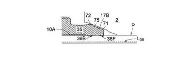
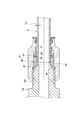
- the cap nut 2 has a hole 11 penetrating in the axial direction (as shown in FIGS. 1 to 3), and a female screw portion 9 is screwed to the base end of the hole 11. It has a threaded portion 12, and from the female threaded portion 12 toward the tip, a seal groove 13 having a small width dimension W 13 in the axial direction, a first same diameter portion (first straight portion) 14A, and a second identical portion. diameter (second straight portion) 14B, stepped portion 15, the short straight section 16 of the narrow dimension W 16, tip diameter tapered portion 17, and, of slightly larger inner diameter than the outer diameter of (the connected pipe P ) The straight portion 18 is formed.
- a concave groove portion 19 is formed in the straight portion 18, and a seal 48 such as an O-ring is attached. Further, another seal 46 such as an O-ring is attached to the seal groove 13.
- the first same diameter portion 14A is set to have an inner diameter slightly larger than that of the second same diameter portion 14B.
- a storage space portion E for accommodating the stop ring 3 is formed by the same diameter portions 14A and 14B, the stepped portion 15, the short straight portion 16, and the tip diameter reduction tapered portion 17 of the hole portion 11.
- the material of the bag nut 2 is brass (brass) or aluminum.
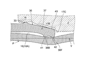
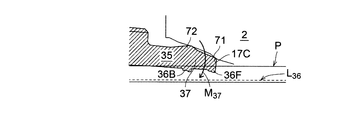
- the tip diameter reduced taper portion 17 has a base end side steep slope taper portion 17A, a tip end side gentle slope taper portion 17B, and the like. It is configured. It is also preferable to add a steeply inclined tapered portion 17C at the innermost part. As shown in FIG. 3B, the corners of the stepped portion 15 and the short straight portion 16 are defined as rounded chamfers r.
- the first and second same diameter portions 14A and 14B having slightly different inner diameter dimensions are used as the same diameter portion (straight portion) 14 has been described with reference to FIG. In some cases, the same diameter portion 14A and the second same diameter portion 14B may have exactly the same inner diameter.
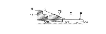
- the stop ring 3 As shown in FIGS. 4 and 1 to 3, the stop ring 3 is installed in the storage space E of the bag nut 2.
- the stop ring 3 has a substantially short cylindrical shape, and the outer peripheral surface is slidably fitted to the straight portion 14 of the hole portion 11 of the bag nut 2 from the base end to the intermediate region with the basic outer diameter portion 24. It has a thin-walled substantially cylindrical portion 35 having a small diameter and a taper that gently expands to the tip, which is continuously provided on the tip side via the stepped portion 25.
- the inner peripheral surface 27 has a basic inner diameter portion 28 in the middle in the axial direction, and the pipe P is inserted into the basic inner diameter portion 28 (as shown in FIG. 1).
- an inner protrusion portion 29 having a small diameter inner peripheral surface portion 29A is continuously provided at the base end portion of the basic inner diameter portion 28.
- One end surface (in the shape of an orthogonal plane of the axis) of the inner protrusion 29 becomes a stepped surface 30.
- Reference numeral 32 denotes a rounded (convex) pressure contact gradient surface, which is formed at the base end of the stop ring 3 and is pressed against the tip diameter reduction gradient surface 5 of the joint body 1 as shown in FIGS. It acts as a seal.
- annular small ridge 40 is provided at the intersection of the inner peripheral edge of the rounded pressure contact gradient surface 32 and the small diameter inner peripheral surface portion 29A. Specifically, as shown in FIGS. 1 and 2, with respect to the annular tip edge portion 20 formed by the tip of the tip diameter-reduced gradient surface 5 of the joint body 1 and the hole 6 of the joint body.
- the stop ring 3 has an annular small ridge 40 that is hooked from the inner diameter side.
- the small ridge 40 has a horizontal triangular cross-sectional shape, and the inner edge of the rounded (convex) pressure contact gradient surface 32 is passed through the small rounded recess 21.
- the small hypotenuse inverted outward and the small diameter inner peripheral surface portion 29A form a sideways triangle.
- the stop ring 3 is formed by forming the annular small ridge 40 from the inner diameter side into a hook shape as shown in FIGS. 1 and 2 with respect to the annular tip edge portion 20 of the joint body 1. It is possible to prevent the base end portion of the tire from being excessively deformed to the outside of the radial tire.
- At least the inner portion 31 of the pipe insertion hole portion 3A of the stop ring 3 is formed in a tapered inner diameter. That is, in FIG. 4, at least the inner portion 31 is formed in a tapered shape with an extremely small gradient angle ⁇ for example, 0.5 ° ⁇ ⁇ ⁇ 2 ° ⁇ , and the pipe insertion shown in FIG.
- the tip portion 10 of the pipe P is configured to be pressed against the inner peripheral surface 27 of the pipe insertion hole portion 3A at the inner peripheral portion 31.
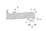
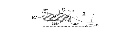
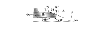
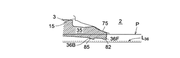
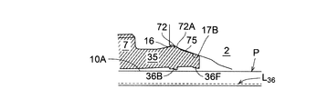
- the stop ring 3 integrally has a thin-walled substantially cylindrical portion 35 that can be plastically deformed on the tip side. Further, a tooth portion 36 for preventing pipe withdrawal is provided on the tip head portion 37 of the thin-walled substantially cylindrical portion 35. As shown in the enlarged cross section in FIG. 5 or 6, the tooth portion 36 is composed of the rear teeth 36B and the front teeth 36F arranged with a minute interval W 36 .
- the thin-walled substantially cylindrical portion 35 has a conical cylinder shape whose diameter increases toward the tip (see FIGS. 4, 5, and 6). Further, the direction of the tip (right) in FIGS. 1, 2 and 4 is referred to as the rear tooth 36B and the front tooth 36F by referring to the "front" direction.
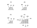
- the cross-sectional shape of the rear tooth 36B is a trapezoid or a substantially trapezoid having a linear first tip side 41 as an upper side.
- FIG. 7 can be seen as an enlarged cross-sectional view showing the X portion of FIG. 4 in an enlarged manner.
- FIG. 7A shows a case where the cross-sectional shape of the rear tooth 36B is trapezoidal
- FIG. 7B shows a substantially trapezoidal shape in which the left and right hypotenuses are concave and curved
- FIG. 7C shows a case where the left and right hypotenuses of the trapezoid are trapezoidal.
- the case where the posterior hypotenuse is steep and the anterior hypotenuse is concave and curved is illustrated.
- FIG. 8 is an enlarged cross-sectional view showing the X portion of FIG. 4 in an enlarged manner.
- FIG. 8A shows a case where the cross-sectional shape of the front teeth 36F is a trapezoid
- FIG. 8B shows a trapezoid in which the front hypotenuse of the trapezoid is steep.
- FIG. 8C the front hypotenuse of the left and right hypotenuses of the trapezoid is steep, and the rear hypotenuse is concave and curved.
- the cross-sectional shape of both the rear teeth 36B and the front teeth 36F has a straight upper side, and can be called a "table mounting type".
- the thin-walled substantially cylindrical portion 35 having the rear teeth 36B and the anterior teeth 36F at the tip is a conical cylinder with an enlarged diameter in the tip direction as a whole, but is attached to the tip of the cylindrical portion 35.
- the first tip side 41 of the rear tooth 36B and the second tip side 42 of the front tooth 36F are formed in parallel with each other, and in a free state, from the second tip side 42 of the front tooth 36F as shown in FIG.
- the first tip side 41 of the rear tooth 36B is set so as to be in the radial inward direction by the minute dimension ⁇ H. (So to speak, they are arranged in parallel steps.) Further, as shown in FIG.
- the cutting-edge radial outer portion 38 of the tip head 37 in FIG. 5 has a rounded rounded shape. Further, the tip head portion 37 in FIG. 6 has a tip diameter-reduced slope portion 43.
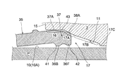
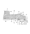
- the thin-walled substantially cylindrical portion 35 in the free state shown in FIG. 6 is sequentially deformed as the bag nut 2 is screwed, as shown in FIGS. 9, 10, 11, 12, and 13 and 14. I will go. That is, with respect to the outer peripheral surface 10A of the straight tip portion 10 of the connected pipe P, the first tip side 41 of the rear tooth 36B of the stop ring 3 and the second tip side 42 of the front tooth 36F are in the radial reduction direction (inside the radial). In the direction), in the final connection completion state, as shown in FIGS. 13 and 14, with the large pressure contact surface pressure indicated by arrows P 41 and P 42 , a strong pressure contact state is established and a large pipe pull-out resistance is obtained. Generates force Z.
- FIG. 10A When the rear teeth 36B and the front teeth 36F are strongly pressed against the pipe outer peripheral surface 10A, the tooth portion 36 composed of the rear teeth 36B and the front teeth 36F fully exerts a sealing function against a fluid such as a refrigerant, and FIG.
- a sealing material is provided between the inner peripheral surface of the stop ring 3 and the outer peripheral surface of the pipe 10A, and between the outer peripheral surface of the stop ring 3 and the inner peripheral surface of the hole 11 of the bag nut 2. Omitted. That is, the O-ring 58 in FIG. 50 showing the conventional example is omitted.
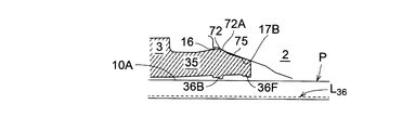
- the tip reduced diameter tapered portion 17 of the hole portion 11 of the bag nut 2 has a base end side steep slope tapered portion 17A (following the short straight portion 16) and a tip side gentle slope tapered portion 17B. It is composed of.
- the outermost diameter portion 37A of the tip head portion 37 of the thin-walled substantially cylindrical portion 35 in the free state shown in FIG. 6 is set to have the same diameter as the inner diameter dimension of the short straight portion 16 or slightly smaller.
- the tip head portion 37 can be easily penetrated into the state shown in FIG. That is, the cutting edge rounded portion 38A of the tip head 37 corresponds to the steeply inclined tapered portion 17A (as shown in FIG. 9).
- the rounded portion 38A reaches the boundary between the steeply inclined tapered portion 17A and the gentlely inclined tapered portion 17B (see FIG. 10), and at this time, with respect to the outer peripheral surface 10A of the pipe P. , The first tip side 41 of the rear tooth 36B and the second tip side 42 of the front tooth 36F start contact. If the bag nut 2 is continuously screwed, as shown in FIGS. 11 and 12, the slope portion 43 is in sliding contact with the gentle slope tapered portion 17B and maintains the same slope (tilt angle). The tip head 37 moves in the radial inward direction, and the pipe P locally undergoes diameter reduction deformation. Further, when the bag nut 2 is screwed, the final tightening state shown in FIGS. 13 and 14 is obtained.
- a relatively soft pipe P such as copper (Cu) undergoes a diameter reduction deformation locally and becomes a shape as shown in FIGS. 13 and 14 through FIG. 12 (from FIG. 11), but the first tip side 41 And the second tip side 42 are kept parallel to each other (see FIG. 6), and are in a strong pressure contact state with respect to the outer peripheral surface 10A of the pipe P, and exhibit a large pipe pull-out resistance force Z.
- the broken line Y indicates a reference line parallel to the axis of the pipe P. That is, it is for clearly showing how the outer peripheral surface 10A of the pipe P is deformed with reference to this reference line (broken line) Y, and the tilted posture and relative positional relationship between the rear teeth 36B and the front teeth 36F. Is.
- the configuration for making the pull-out resistance force (vector) Z B of the rear tooth 36B and the pull-out resistance force (vector) Z F of the front tooth 36F substantially equal will be described below.
- the first tip side 41 of the rear tooth 36B and the second tip side 42 of the front tooth 36F are parallel to each other with a minute (step) dimension ⁇ H, and the first tip side 41 is the second tip side. Arrange it as a radial inside rather than 42.
- the second tip side 42 is made to protrude radially inward from the first tip side 41, or both tip sides 42.
- the outer peripheral surface (slope portion) 43 of the tip head 37 is sufficiently in contact with the gentle slope tapered portion 17B to maintain a stable posture. It is formed in a straight inclined shape with various axial dimensions. Then, the straight line connecting the rear teeth 36B and the front teeth 36F (not shown) is parallel to the broken line Y shown in FIG. 14 (FIG. 13), or gradually becomes the broken line Y as it goes toward the tip (forward). The radial positions of the rear teeth 36B and the front teeth 36F are set so as to approach each other. In the case of the shape shown in FIG. 5, the tip head 37 is slightly larger inward in the radial direction, and the gentle slope taper portion 17B of the tip diameter reduction taper portion 17 and the innermost contact are made so as to swing the head. Set the dimensions and shape of the steep taper portion 17C.
- a small protrusion 33 is attached to the outer peripheral surface of the thin-walled substantially cylindrical portion 35 of the stop ring 3.
- the small protrusion 33 has a substantially trapezoidal shape.
- the small protrusion 33 corresponds to the short straight portion 16 of the bag nut 2, and when the thin-walled substantially cylindrical portion 35 tries to be excessively expanded and deformed under a pressure receiving state. , The small protrusion 33 abuts on the inner surface of the hole 11 of the bag nut 2 to prevent it.
- the small protrusion 33 corresponds to the short straight portion 16 of the hole portion 11 (see FIG. 13).
- the thin-walled substantially cylindrical portion 35 is particularly slidable with the inner peripheral surface of the hole portion 11 only by the tip head 37.
- the rotational torque when rotating 2 with a work tool is small, and there is an advantage that the work can be done lightly. Further, there is an advantage that the small protrusion 33 abuts on the short straight portion 16 to center the thin-walled substantially cylindrical portion 35 near the final and under the final tightening state shown in FIGS. 12 and 13.
- seals 46 and 48 such as O-rings are provided in FIGS. 1 and 2, they are not for preventing external leakage of a fluid such as a refrigerant, but for a pressure welding portion, a plastic deformation portion, etc. in the present invention.
- O-ring resistant rubber is desirable because it is for preventing stress corrosion.
- the present invention is not limited to the illustrated embodiment, and the design can be freely changed.
- the short straight portion 16 of the bag nut 2 may be omitted, or the bag nut 2 may have a gentle taper shape.
- the flare joint body 1 having the male screw portion 9 and the tip diameter reduction gradient surface 5 and the male screw portion are described.
- a female screw portion 12 screwed into 9 is provided at the base end of the hole portion 11, and an same diameter portion 14, a stepped portion 15, and a tip diameter reduction tapered portion 17 are provided in the middle of the hole portion 11.
- It has a bag nut 2 forming a storage space E, a base end side pressure contact slope surface 32 that is internally provided in the storage space E and is in pressure contact with the tip diameter reduction slope surface 5, and is plastically deformed on the tip side.
- the tooth portions 36 are arranged with a minute interval W 36.
- the rear tooth 36B is composed of the provided rear tooth 36B and the front tooth 36F, and the cross-sectional shape of the rear tooth 36B is a trapezoidal shape or a substantially trapezoidal shape having a linear first tip side 41 as an upper side, and the cross-sectional shape of the front tooth 36F is a straight line.
- It is a trapezoidal or substantially trapezoidal shape having a second tip side 42 as an upper side, and has a first tip side 41 of the rear tooth 36B of the stop ring 3 with respect to the outer peripheral surface 10A of the straight tip portion 10 of the connected pipe P. Since the second tip side 42 of the front tooth 36F is configured to be in a strong pressure contact state with the screwing of the bag nut 2 to generate a pipe pull-out resistance force Z, the bag nut 2 is screwed. The stop ring 3 does not rotate together with the pipe P, and the stop ring 3 continues to stand still integrally with the pipe P. Therefore, it is possible to prevent the occurrence of relative slip between the slope surface 5 of the joint body 1 and the rounded pressure contact slope portion 32.
- the "preliminary processing" using a special jig described as the unsolved problem (i) in the conventional pipe joint (shown in FIG. 50) can be omitted.
- work efficiency at the pipe connection site is dramatically improved.
- the pull-out force of the pipe is a trapezoidal or substantially trapezoidal first tip side 41 and a second tip side 42, which provides a strong surface pressure welding state. Therefore, a claw with a triangular cross section in a conventional pipe joint (see FIG. 50). It was much stronger than Part 61.
- the rear teeth 36B and the front teeth 36F of the tooth portion 36 are strongly pressed against the outer peripheral surface 10A as the bag nut 2 is screwed, and the rear teeth 36B and the front teeth 36F exert a sealing function. Since the sealing material is omitted from the inner peripheral surface and the outer peripheral surface of the stop ring 3, it is possible to omit an expensive sealing material (O-ring 58 shown in FIG. 50 in the past), which is particularly expensive for refrigerant resistance. , The troublesome processing of the concave groove for sealing on the stop ring 3 can be omitted.
- the tip reduced diameter tapered portion 17 is composed of a base end side steep slope tapered portion 17A and a tip side gentle gradient tapered portion 17B, so that the bag nut 2 is screwed. It is possible to improve the efficiency of pipe connection work by reducing the number of advances. That is, at the initial stage of screwing of the bag nut 2 (see the state of FIGS. 9 to 10) in which the thin-walled substantially cylindrical portion 35 can be reduced in diameter with a small force, the diameter is reduced by a slight rotation of the bag nut 2. It is possible to reduce the total number of times the bag nut 2 is screwed.
- the rear teeth 36B and the front teeth 36F are configured to share the pipe pull-out resistance force Z substantially equally with respect to the outer peripheral surface 10A of the pipe P in the strong pressure contact state, as shown in FIG. ,
- the pipe pull-out resistance Z is a sufficiently large value as (Z B + Z F ), and exhibits excellent pull-out resistance in practical use.
- the tooth portion does not stick and escapes as shown in FIGS. 12 to 13 and 14, even under such adverse conditions. , Practically, a sufficiently large pull-out resistance can be obtained.
- the first tip side 41 of the rear tooth 36B and the second tip side 42 of the front tooth 36F are parallel to each other, and the first tip side 41 is set.
- the second tip side 42 is arranged radially inward from the second tip side 42, and in the strong pressure contact state, the second tip side 42 protrudes radially inward from the first tip side 41, or the above
- the inclination angle of the tip reduced diameter tapered portion 17 on the tip side and the shape and dimensions of the tip head 37 are set so that the second tip side 42 and the first tip side 41 are at the same position in the radial direction.
- either the rear tooth 36B or the front tooth 36F does not "play", and each exhibits substantially the same pull-out resistance Z B and Z F , and the overall pipe pull-out resistance Z becomes sufficiently large.
- excellent pull-out resistance can be obtained in practice.
- the tooth portion is not inserted and the outer peripheral surface 10A of the pipe escapes in a curved concave shape while being plastically deformed (see FIGS. 12 to 13 and 14). .. Even under such adverse conditions, a sufficiently large pull-out resistance can be obtained.
- the thin-walled substantially cylindrical portion 35 having the rear tooth 36B and the front tooth 36F at the tip has a conical cylinder shape having an enlarged diameter in the tip direction
- the thin-walled substantially cylindrical portion 35 with respect to the tip diameter-reduced tapered portion 17 of the bag nut 2 is substantially formed.
- the contact area of the outer peripheral surface of the cylindrical portion 35 is small (compared to the cylindrical type having the same diameter), the rotational torque of the bag nut 2 is small, and the amount of work (energy) required for rotation is also small. Excellent screwing workability. Further, the torque for rotating the stop ring 3 together is also reduced.
- a small protrusion 33 for preventing the thin-walled substantially cylindrical portion 35 from being deformed due to excessive diameter expansion is attached to the outer peripheral surface of the thin-walled substantially cylindrical portion 35 to form the small protrusion 33. Since the bag nut 2 is configured to come into contact with the inner surface of the hole portion 11, the thin-walled substantially cylindrical portion 35 is sufficiently thinned without abnormally expanding and deforming the diameter of the thin-walled substantially cylindrical portion 35 under pressure receiving conditions. it can. When the wall thickness is sufficiently thin, the rotational torque of the bag nut 2 can be reduced, the amount of work (energy) required for rotation can be reduced, and the screwing workability of the bag nut 2 is improved.
- annular small ridge 40 that is hooked from the inner diameter side to the annular tip edge portion 20 formed by the tip of the tip diameter reduction gradient surface 5 of the joint body 1 and the joint body hole portion 6 is formed. It is attached to the inner peripheral edge of the pressure contact slope surface 32 on the base end side of the stop ring 3 so as to prevent the base end portion of the stop ring 3 from being excessively deformed radially outward.
- the mutual attitude of the slope surface 5 of 1 and the pressure contact slope surface 32 of the stop ring 3 is stable, and the sealing performance of the metal touch portion is stably ensured. Further, it is possible to prevent the outer peripheral surface of the base end of the stop ring 3 from being locally expanded in diameter to prevent the bag nut 2 from being screwed.
- At least the inner peripheral portion 31 of the pipe insertion hole portion 3A of the stop ring 3 is formed in a tapered inner diameter, and the straight tip portion 10 is the inner peripheral surface of the pipe insertion hole portion 3A when the pipe insertion is completed. Since it is configured to be in pressure contact with 27, even if an external force in the direction of swinging the pipe P acts, the pipe P is maintained so as to completely coincide with each other with respect to the stop ring 3. Therefore, when such an external force acts on the pipe P, a swinging motion is caused around the tip head 37 of the thin-walled substantially cylindrical portion 35 that strongly holds the pipe P, and the rear teeth 36B and the front teeth 36F are generated. It is possible to prevent the strong pressure welding state (holding state) from being destroyed.
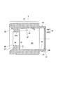
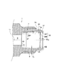
- the pipe joint J includes a joint body 1 and bag nuts 2 and 2.
- the point that the tip of the pipe P has a straight tip 10 is the same as that of the first embodiment described above.
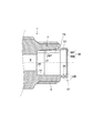
- the joint body 1 has a straight shape as a whole, a flow path hole 6 is formed along the axis, and a hexagon or the like for hanging a work tool such as a spanner is gripped at the center position in the axis direction.
- a holding portion 1A is provided, and connecting cylinder portions 7 and 7 are continuously provided in the left-right direction of the axis.
- a male screw portion 9 is formed on the outer peripheral surface of each connection cylinder portion 7. Then, the two bag nuts 2 and 2 are screwed to the left and right male screw portions 9 and 9.
- a thin-walled substantially cylindrical portion 35 is integrally extended from the tip surface 7A of the connecting cylinder portion 7.
- a connecting cylinder portion 7 having a male screw portion 9 on the outer peripheral surface and a taper shape having a small diameter and gently expanding to the tip, which are connected to the tip side (via the tip surface 7A as a stepped portion). It has a thin-walled substantially cylindrical portion 35. Therefore, the thin-walled substantially cylindrical portion 35 is a conical cylinder type whose diameter increases toward the tip end.
- the flow path hole (hole portion) 6 has a stepped portion 30, and the diameter of the left and right outer portions is larger than the central basic diameter, and the pipe P reaches the stepped portion 30 (or near it). It has been inserted.
- the inner portion 31 (explained earlier) is formed in a tapered inner diameter to insert the pipe.
- the pipe outer peripheral surface 10A is formed so as to be in pressure contact with the inner peripheral surface 27 of the hole 28P.
- the inner diameter dimension of the base end of the thin-walled substantially cylindrical portion 35 matches the inner diameter dimension of the tip of the pipe insertion hole portion 28P, and the inner peripheral surface shape of the thin-walled substantially cylindrical portion 35. Is a tapered shape that gradually expands in the tip direction.
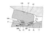
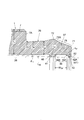
- a pull-out prevention tooth portion 36 is provided on the inner peripheral surface of the tip head portion 37 of the thin-walled substantially cylindrical portion 35. Similar to FIGS. 5 and 6 described in the first embodiment, the tooth portion 36 is composed of rear teeth 36B and front teeth 36F arranged with a minute interval W 36 . In this way, the joint body 1 itself integrally has the pull-out preventing tooth portion 36 ⁇ the rear tooth 36B and the front tooth 36F ⁇ that exerts the pipe pull-out resistance force.
- FIGS. 15 and 16 the overall shape is shown as a straight shape, but this can be freely T-shaped, Y-shaped, cross-shaped, elbow-shaped, or the like. Further, in FIGS. 15 and 16, the case where the thin-walled substantially cylindrical portion 35 is provided at both ends for connection is shown, but this unique thin-walled substantially cylindrical portion 35 is provided only at one end, and the other end is provided with a tapered male screw or parallel. A connection structure having a female screw, a welding cylinder, or the like is also free.
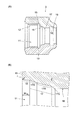
- the cap nut 2 has a smaller axial dimension than that of FIG. 3 (A) shown in the first embodiment, and has a hole 11 in the axial direction (as shown in FIGS. 15 to 17).
- a female screw portion 12 At the base end of the hole portion 11, there is a female screw portion 12 to which the male screw portion 9 is screwed, and the female screw portion 12 is sequentially smaller toward the tip in the axial direction.
- Width dimension relief groove 13, stepped portion 15, narrow dimension W 16 short straight portion 16, tip reduced diameter tapered portion 17, and straight portion (with an inner diameter slightly larger than the outer diameter of the connected pipe P) 18 is formed.
- a concave groove portion 19 is formed on the straight portion 18, and a seal 48 such as an O-ring is attached.
- a seal 48 such as an O-ring is attached.
- the base end portion of the bag nut 2 and the vicinity of the tip surface of the grip portion 1A of the joint body 1 are formed with metal seals Ms (see FIG. 16) by pressure welding between the metals under the screwed state of the bag nut 2. Therefore, the sealing material is omitted.
- the material of the bag nut 2 is brass (brass) or aluminum.
- the tip diameter-reduced tapered portion 17 includes a proximal end side steep slope tapered portion 17A, an intermediate gentle gradient tapered portion 17B, and the like. Has been done. It is also preferable to add a steep taper portion 17C (at the innermost part). As shown in FIG. 17B, the corners of the stepped portion 15 and the short straight portion 16 are defined as rounded chamfers r.
- FIG. 18 showing the enlargement of the main part of the joint body 1 will be additionally described. That is, it is preferable to form the inner portion 31 in a tapered shape with an extremely small gradient angle ⁇ for example, 0.5 ° ⁇ ⁇ ⁇ 2 ° ⁇ .
- ⁇ for example, 0.5 ° ⁇ ⁇ ⁇ 2 ° ⁇ .
- the thin-walled substantially cylindrical portion 35 of the joint body 1 has the rear teeth 36B and the front teeth 36F protruding from the inner peripheral surface of the tip with a minute interval W 36 .
- the left and right tip directions are referred to as "front” and are referred to as rear teeth 36B and front teeth 36F.
- FIGS. 7 and 5 The shapes of the rear teeth 36B, the front teeth 36F, and the like are the same as those in the first embodiment described above. That is, as shown in FIGS. 7 and 5, the cross-sectional shape of the rear tooth 36B is a trapezoid or a substantially trapezoid having a linear first tip side 41 as an upper side.
- FIG. 7 can be seen as an enlarged cross-sectional view showing the X portion of FIG. 18 in an enlarged manner.
- FIG. 7A shows a case where the cross-sectional shape of the rear tooth 36B is trapezoidal
- FIG. 7B shows a substantially trapezoidal shape in which the left and right hypotenuses are concave and curved
- FIG. 7C shows a case where the left and right hypotenuses of the trapezoid are trapezoidal.
- the case where the posterior hypotenuse is steep and the anterior hypotenuse is concave and curved is illustrated.
- FIG. 8 is an enlarged cross-sectional view showing the X portion of FIG. 4 in an enlarged manner.
- FIG. 8A shows a case where the cross-sectional shape of the front teeth 36F is a trapezoid
- FIG. 8B shows a trapezoid in which the front hypotenuse of the trapezoid is steep.
- FIG. 8C the front hypotenuse of the left and right hypotenuses of the trapezoid is steep, and the rear hypotenuse is concave and curved.
- the cross-sectional shape of both the rear teeth 36B and the front teeth 36F has a straight upper side, and can be called a "table mounting type".
- the thin-walled substantially cylindrical portion 35 having the rear teeth 36B and the anterior teeth 36F at the tip is, as a whole, a conical cylinder having an enlarged diameter in the tip direction.
- the first tip side 41 of the rear tooth 36B and the second tip side 42 of the front tooth 36F, which are attached to the tip of the portion 35, are formed in parallel with each other, and under a free state, as shown in FIG. 5, the front tooth 36F
- the first tip side 41 of the rear tooth 36B is set so as to be in the radial inward direction by a minute dimension ⁇ H rather than the second tip side 42 of the above. (So to speak, they are arranged in parallel steps.)
- the cutting-edge radial outer portion 38 of the tip head 37 has a rounded rounded shape (see FIG. 5), and the tip head 37 has a shape having a tip diameter-reduced slope portion 43 (see FIG. 6). ).
- the operation and function of the thin-walled substantially cylindrical portion 35, the rear teeth 36B and the front teeth 36F are the same as those in the first embodiment described above. That is, the thin-walled substantially cylindrical portion 35 in the free state shown in FIG. 6 is sequentially as shown in FIGS. 9, 10, 10, 11, 12, and 13 and 14 as the bag nut 2 is screwed. It transforms.
- the first tip side 41 of the rear teeth 36B of the joint body 1 and the second tip side 42 of the front teeth 36F are in the radial inward direction.
- a strong pressure contact state is obtained with the large pressure contact surface pressure indicated by arrows P 41 and P 42 , and a large pipe pull-out resistance force Z Occurs.
- the tooth portion 36 composed of the rear teeth 36B and the front teeth 36F fully exerts a sealing function against a fluid such as a refrigerant, and FIG.
- the sealing material is omitted between the inner peripheral surface of the joint body 1 and the outer peripheral surface 10A of the pipe. That is, the O-ring 58 in FIG. 50 showing the conventional example is omitted.
- the tip reduced diameter tapered portion 17 of the hole portion 11 of the bag nut 2 (as described above) has a base end side steep slope tapered portion 17A (following the short straight portion 16) and an intermediate gentle gradient tapered portion 17B. ,It is configured.
- the outermost diameter portion 37A of the tip head portion 37 of the thin-walled substantially cylindrical portion 35 in the free state shown in FIG. 6 is set to have the same diameter as the inner diameter dimension of the short straight portion 16 or slightly smaller.
- the slope portion 43 is formed, the tip head portion 37 can be easily penetrated into the state shown in FIG. That is, the cutting edge rounded portion 38A of the tip head 37 corresponds to the steeply inclined tapered portion 17A (as shown in FIG. 9).
- the rounded portion 38A reaches the boundary between the steeply inclined tapered portion 17A and the gentlely inclined tapered portion 17B (see FIG. 10), and at this time, with respect to the outer peripheral surface 10A of the pipe P. , The first tip side 41 of the rear tooth 36B and the second tip side 42 of the front tooth 36F start contact. If the bag nut 2 is continuously screwed, as shown in FIGS. 11 and 12, the slope portion 43 is in sliding contact with the gentle slope tapered portion 17B and maintains the same slope (tilt angle). The tip head 37 moves in the radial inward direction, and the pipe P locally undergoes diameter reduction deformation. Further, when the bag nut 2 is screwed, the final tightening state shown in FIGS. 13 and 14 is obtained.
- a relatively soft pipe P such as copper (Cu) undergoes a diameter reduction deformation locally and becomes a shape as shown in FIGS. 13 and 14 through FIG. 12 (from FIG. 11), but the first tip side 41 And the second tip side 42 are kept parallel to each other (see FIG. 6), and are in a strong pressure contact state with respect to the outer peripheral surface 10A of the pipe P, and exhibit a large pipe pull-out resistance force Z.
- the broken line Y indicates a reference line parallel to the axis of the pipe P. That is, it is for clearly showing how the outer peripheral surface 10A of the pipe P is deformed with reference to this reference line (broken line) Y, and the tilted posture and relative positional relationship between the rear teeth 36B and the front teeth 36F. Is.
- the configuration for making the pull-out resistance force (vector) Z B of the rear tooth 36B and the pull-out resistance force (vector) Z F of the front tooth 36F substantially equal will be described below.
- the first tip side 41 of the rear tooth 36B and the second tip side 42 of the front tooth 36F are parallel to each other with a minute (step) dimension ⁇ H, and the first tip side 41 is the second tip side. Arrange it as a radial inside rather than 42.
- the second tip side 42 is made to protrude radially inward from the first tip side 41, or both tip sides 42.
- the outer peripheral surface (slope portion) 43 of the tip head 37 is sufficiently in contact with the gentle slope tapered portion 17B to maintain a stable posture. It is formed in a straight inclined shape with various axial dimensions. Then, the straight line connecting the rear teeth 36B and the front teeth 36F (not shown) is parallel to the broken line Y shown in FIG. 14 (FIG. 13), or gradually becomes the broken line Y as it goes toward the tip (forward). The radial positions of the rear teeth 36B and the front teeth 36F are set so as to approach each other. In the case of the shape shown in FIG. 5, the tip head 37 is slightly larger inward in the radial direction, and the gentle slope taper portion 17B of the tip diameter reduction taper portion 17 and the innermost contact are made so as to swing the head. Set the dimensions and shape of the steep taper portion 17C.
- a small protrusion 33 is attached to the outer peripheral surface of the thin-walled substantially cylindrical portion 35 of the joint body 1 itself.
- the small protrusion 33 has a substantially trapezoidal shape. As shown in FIGS. 12 and 13, the small protrusion 33 corresponds to the short straight portion 16 of the bag nut 2, and when the thin-walled substantially cylindrical portion 35 tries to be excessively expanded and deformed under a pressure receiving state. , The small protrusion 33 abuts on the inner surface of the hole 11 of the bag nut 2 to prevent it. In particular, the small protrusion 33 corresponds to the short straight portion 16 of the hole portion 11 (see FIG. 13).
- seals 48 such as O-rings are provided in FIGS. 15 and 16, they are not for preventing external leakage of fluid such as refrigerant, but for stress corrosion cracking of pressure welding portions and plastic deformation portions in the present invention.
- O-ring resistant rubber is desirable because it is for preventing the above.
- the present invention is not limited to the illustrated embodiment, and the design can be freely changed.
- the short straight portion 16 of the bag nut 2 may be omitted, or the bag nut 2 may have a gentle taper shape.
- the outer peripheral surface of the connected pipe P is accompanied by the screwing of the bag nut 2 to the joint body 1. Since the joint body 1 itself has a pull-out prevention tooth portion 36 that is in a strong pressure contact state with respect to 10A and generates a pipe pull-out resistance force Z, the bag nut 2 is simply screwed. , Exhibits a large pull-out resistance Z on the connected pipe P.
- the pipe connection work that exhibits reliable sealing performance can be performed easily and quickly. In particular, the number of parts is small, there is no risk of losing small parts, the dimensions in the axial direction can be significantly reduced, and compactness can be achieved.
- the present invention is for preventing the pipe from being pulled out by causing a strong pressure contact with the outer peripheral surface 10A of the connected pipe P as the cap nut 2 is screwed into the joint body 1 and generating a pipe pull-out resistance force Z.
- the joint body 1 itself has the tooth portion 36 integrally, and the pull-out prevention tooth portion 36 is formed at the tip of the thin-walled substantially cylindrical portion 35 protruding from the tip of the joint body 1 to prevent the pull-out.
- the tooth portion 36 is composed of a rear tooth 36B and an anterior tooth 36F arranged with a minute interval W 36, and the cross-sectional shape of the rear tooth 36B is a trapezoidal shape or a substantially trapezoidal shape having a linear first tip side 41 as an upper side.
- the cross-sectional shape of the front tooth 36F is a trapezoidal shape or a substantially trapezoidal shape having a linear second tip side 42 as an upper side, and the rear tooth 36B of the joint body 1 with respect to the outer peripheral surface 10A of the connected pipe P. Since the first tip side 41 and the second tip side 42 of the front tooth 36F are in a strong pressure-welding state as the bag nut 2 is screwed, a pipe pull-out resistance force Z is generated. As for the pull-out resistance, a surface strong pressure contact state can be obtained by the first tip side 41 and the second tip side 42 of a trapezoidal or substantially trapezoidal shape (see FIG. 14), and a sufficiently strong pull-out force can be exhibited.
- the bag nut 2 has a female screw portion 12 screwed to the male screw portion 9 of the joint body 1 at the base end of the hole portion 11, and is stepped in the middle of the hole portion 11.
- a bag is provided with a portion 15 and a tip-reduced taper portion 17, and further, the tip-reduced taper portion 17 is composed of a base end-side steep slope taper portion 17A and an intermediate gentle slope taper portion 17B.
- the number of screwing of the nut 2 can be reduced to improve the efficiency of the pipe connection work. That is, at the initial stage of screwing of the bag nut 2 (see the state of FIGS.
- the diameter is reduced by a slight rotation of the bag nut 2. It is possible to reduce the total number of times the bag nut 2 is screwed. After that, after the rear teeth 36B and the front teeth 36F come into contact with the outer peripheral surface 10A of the pipe (see FIGS. 11 to 13), the diameter can be slowly reduced by the intermediate gentle slope tapered portion 17B, and the pipe is reasonably screwed. Can do the work.
- the rear teeth 36B and the front teeth 36F are configured to share the pipe pull-out resistance force Z substantially equally with respect to the outer peripheral surface 10A of the pipe P in the strong pressure contact state, as shown in FIG. ,
- the pipe pull-out resistance Z is a sufficiently large value as (Z B + Z F ), and exhibits excellent pull-out resistance in practical use.
- the tooth portion does not stick and escapes as shown in FIGS. 12 to 13 and 14, even under such adverse conditions. , Practically, a sufficiently large pull-out resistance can be obtained.
- the first tip side 41 of the rear tooth 36B and the second tip side 42 of the front tooth 36F are parallel to each other and the first tip side.
- 41 is arranged as radial inward from the second tip side 42, and further, in the strong pressure contact state, the second tip side 42 protrudes in the radial inward direction from the first tip side 41, or
- the inclination angle of the tip side of the tip reduced diameter tapered portion 17 and the shape and dimensions of the tip head 37 are set so that the second tip side 42 and the first tip side 41 are at the same position in the radial direction.
- either the rear tooth 36B or the front tooth 36F does not "play", and each exhibits substantially the same pull-out resistance Z B and Z F , and the overall pipe pull-out resistance Z is sufficiently large.
- excellent pull-out resistance can be obtained in practice.
- the tooth portion is not inserted and the outer peripheral surface 10A of the pipe escapes in a curved concave shape while being plastically deformed (see FIGS. 12 to 13 and 14). .. Even under such adverse conditions, a sufficiently large pull-out resistance can be obtained.
- the thin-walled substantially cylindrical portion 35 having the rear tooth 36B and the front tooth 36F at the tip has a conical cylinder shape having an enlarged diameter in the tip direction
- the thin-walled substantially cylindrical portion 35 with respect to the tip diameter-reduced tapered portion 17 of the bag nut 2 is substantially formed.
- the contact area of the outer peripheral surface of the cylindrical portion 35 is small (compared to the cylindrical type having the same diameter), the rotational torque of the bag nut 2 is small, and the amount of work (energy) required for rotation is also small. Excellent screwing workability.
- a small protrusion 33 for preventing the thin-walled substantially cylindrical portion 35 from being deformed due to excessive diameter expansion is attached to the outer peripheral surface of the thin-walled substantially cylindrical portion 35 to form the small protrusion 33. Since the bag nut 2 is configured to come into contact with the inner surface of the hole portion 11, the thin-walled substantially cylindrical portion 35 is sufficiently thinned without abnormally expanding and deforming the diameter of the thin-walled substantially cylindrical portion 35 under pressure receiving conditions. it can. When the wall thickness is sufficiently thin, the rotational torque of the bag nut 2 can be reduced, the amount of work (energy) required for rotation can be reduced, and the screwing workability of the bag nut 2 is improved.
- the inner peripheral surface 31 of the pipe insertion hole 28P of the joint body 1 is formed in a tapered inner diameter, and the pipe outer peripheral surface 10A is pressed against the inner peripheral surface 27 of the pipe insertion hole 28P when the pipe insertion is completed. Therefore, even if an external force in the direction of swinging the pipe P acts, the pipe P is maintained so as to completely coincide with each other with respect to the hole 28P. Therefore, when such an external force acts on the pipe P, a vibrating motion is caused around the tip head 37 of the thin-walled substantially cylindrical portion 35 that strongly holds the pipe P, and the rear teeth 36B and the front teeth 36F cause vibration. It is possible to prevent the strong pressure welding state (holding state) from being destroyed.
- the pipe joint J includes a flare joint body 1F, a bag nut 2, and a stop ring 3, and is further attached to the tip of the connected pipe P. Has a straight tip 10 (without the conventional flaring process altogether).
- the flare joint body 1F has been used for a long time, is similar to the flare joint body h shown in FIG. 49, and has a tip diameter reduction gradient surface 5. That is, the tip diameter reduction gradient surface 5 is formed at the tip of the connection cylinder portion 7 through which the flow path hole 6 is formed.
- the overall shape can be straight, T-shaped, Y-shaped, cross-shaped, etc., but the shapes of other connecting ends that are not shown in FIGS. 19 and 20 are shown in FIGS. 19 and 20. It is free to have the same connection cylinder portion 7 as above, or to have a tapered male screw, a parallel female screw, a welding cylinder portion, and the like. In short, as shown in FIGS.
- connection cylinder portion 7 has a male screw portion 9 of a parallel screw.
- the cap nut 2 has a hole 11 penetrating in the axial direction (as shown in FIGS. 19 to 21), and a female screw portion 9 is screwed to the base end of the hole 11. It has a threaded portion 12, and from the female threaded portion 12 toward the tip, a seal groove 13 having a small width dimension W 13 in the axial direction, a first same diameter portion (first straight portion) 14A, and a second identical portion. diameter (second straight portion) 14B, stepped portion 15, the short straight section 16 of the narrow dimension W 16, tip diameter tapered portion 17, and, of slightly larger inner diameter than the outer diameter of (the connected pipe P ) The straight portion 18 is formed. In some cases, the short straight portion 16 can be omitted (in the case of a small diameter).
- a concave groove portion 19 is formed in the straight portion 18, and a seal 48 such as an O-ring is attached. Further, another seal 46 such as an O-ring is attached to the seal groove 13.
- the first same diameter portion 14A is set to have an inner diameter slightly larger than that of the second same diameter portion 14B.
- a storage space portion E for accommodating the stop ring 3 is formed by the same diameter portions 14A and 14B, the stepped portion 15, the short straight portion 16, and the tip diameter reduction tapered portion 17 of the hole portion 11. (Note that the short straight portion 16 may be omitted.) As described above, this third embodiment has a part in common with the first embodiment described above.
- the tip diameter reduced taper portion 17 has a base end side steep slope taper portion 17A, an intermediate gentle slope taper portion 17B, and an intermediate steep slope taper portion 17. It is composed of a portion 17C and a tip side gentle slope tapered portion 17D and the like.
- the base end side steep slope taper portion 17A and the intermediate steep slope taper portion 17C are set to have the same gradient (inclination) angle.
- the width dimensions of both steeply inclined tapered portions 17A and 17C are set to be the same. Further, as is clear from FIG.
- the gradient (inclination) angle of the intermediate gentle gradient tapered portion 17B is set to a value equal to the gradient (inclination) angle of the tip side gentle gradient tapered portion 17D, or ,
- the gradient (inclination) angle of the latter tapered portion 17D is set slightly larger.
- the width dimension of the latter tapered portion 17D is smaller.
- the stop ring 3 As shown in FIGS. 22 and 19 to 21, the stop ring 3 is installed in the storage space E of the bag nut 2.
- the stop ring 3 has a substantially short cylindrical shape, and the outer peripheral surface is slidably fitted to the straight portion 14 of the hole portion 11 of the bag nut 2 from the base end to the intermediate region with the basic outer diameter portion 24. It has a thin-walled substantially cylindrical portion 35 having a small diameter and a taper that gently expands to the tip, which is continuously provided on the tip side via the stepped portion 25.
- the inner peripheral surface 27 has a basic inner diameter portion 28 in the middle in the axial direction, and the pipe P is inserted into the basic inner diameter portion 28 (as shown in FIG. 19).
- an inner protrusion portion 29 having a small diameter inner peripheral surface portion 29A is continuously provided at the base end portion of the basic inner diameter portion 28.
- One end surface (in the shape of an orthogonal plane of the axis) of the inner protrusion 29 becomes a stepped surface 30.
- Reference numeral 32 denotes a rounded (convex) pressure contact gradient surface, which is formed at the base end of the stop ring 3 and is pressed against the tip diameter reduction gradient surface 5 of the joint body 1 as shown in FIGS. It acts as a seal.
- the annular small ridge 40 is provided at the intersection of the inner peripheral edge of the rounded pressure contact gradient surface 32 and the small diameter inner peripheral surface portion 29A. .. Specifically, as shown in FIGS. 19, 20, and 22 (A), the annular shape formed by the tip of the tip diameter reduction gradient surface 5 of the joint body 1 and the hole 6 of the joint body 1.
- the stop ring 3 has an annular small ridge 40 that is hooked from the inner diameter side with respect to the tip edge portion 20.
- this small ridge 40 has a horizontal triangular cross-sectional shape, and the inner edge of the rounded (convex) pressure contact gradient surface 32 is formed by the small rounded recess 21.
- a small hypotenuse that is inverted outward through a small diameter and a small diameter inner peripheral surface portion 29A form a sideways triangle.
- the stop ring 3 is formed by forming the annular small ridge 40 from the inner diameter side into a hook shape as shown in FIGS. 19 and 20 with respect to the annular tip edge portion 20 of the joint body 1. It is possible to prevent the base end portion of the tire from being excessively deformed to the outside of the radial tire. As shown in FIG. 22 (B), it may be preferable to omit the annular small ridge 40 shown in FIG. 22 (A).
- At least the inner portion 31 of the pipe insertion hole portion 3A of the stop ring 3 is formed in a tapered inner diameter. That is, in FIG. 22, at least the inner portion 31 is formed in a tapered shape with an extremely small gradient angle ⁇ for example, 0.5 ° ⁇ ⁇ ⁇ 2 ° ⁇ , and the pipe insertion shown in FIG. 20 is performed.
- the tip portion 10 of the pipe P is configured to be pressed against the inner peripheral surface 27 of the pipe insertion hole portion 3A at the inner peripheral portion 31.
- the stop ring 3 integrally has a thin-walled substantially cylindrical portion 35 that can be plastically deformed on the tip side. Further, a tooth portion 36 for preventing pipe withdrawal is provided on the tip head portion 37 of the thin-walled substantially cylindrical portion 35. As shown in the enlarged cross section in FIG. 23, the tooth portion 36 is composed of a rear tooth 36B and an anterior tooth 36F arranged with a minute interval W 36 .
- the thin-walled substantially cylindrical portion 35 has a conical cylinder shape with a slightly enlarged diameter toward the tip (see FIGS. 22 and 23). Then, in FIGS.
- the wall thickness dimension of the basic short cylindrical portion 50 including the basic inner diameter portion 28 and the basic outer diameter portion 24 is set to T 50, and further, the average of the thin-walled substantially cylindrical portions 35.
- the wall thickness dimension is T 35
- the thin-walled substantially cylindrical portion 35 is formed to be relatively thick so that 0.40 ⁇ T 50 ⁇ T 35 ⁇ 0.75 ⁇ T 50 (Formula 1) holds.
- the average wall thickness dimension T 35 of the thin-walled substantially cylindrical portion 35 is sufficiently large, 40% to 75% of the wall-thickness dimension T 50 of the basic short cylindrical portion 50. It should be noted that preferably, it is set as 0.43 ⁇ T 50 ⁇ T 35 ⁇ 0.65 ⁇ T 50 (Formula 2). Further, preferably, it is set as 0.45 ⁇ T 50 ⁇ T 35 ⁇ 0.55 ⁇ T 50 (Formula 3). In the above formula, it is difficult to withstand the internal pressure below the lower limit. On the contrary, when the upper limit value is exceeded, the step size of the stepped portion 25 becomes too small, and it becomes difficult for the operator to detect an increase in the screwing resistance of the bag nut 2 (described later). Further, when the value is less than the lower limit value or exceeds the upper limit value, the tip head portion 37 does not bite (narrow down) into the outer peripheral surface 10A of the pipe P reliably and smoothly as shown in FIGS. 26 to 33 (described later).
- the direction of the tip (right) in FIGS. 19, 20, and 22 is referred to as the rear tooth 36B and the front tooth 36F by referring to the "front" direction.
- the cross-sectional shape of the rear teeth 36B is substantially trapezoidal, and the first tip side 41 formed of the substantially trapezoidal upper side is a rounded intermediate step portion. Through 62, it has a short second half 63 and a tall front half 64.
- the cross-sectional shape of the rear teeth 36B is a trapezoid or a substantially trapezoid having a linear first tip side 41 as an upper side (see FIGS. 24 (A), (B), (C), and (D)). Note that FIG. 24 can be seen as an enlarged view of the rear tooth 36B in the X portion of FIG. 22.
- FIG. 24 (A) shows a case where the cross-sectional shape of the rear tooth 36B is trapezoidal
- FIG. 24 (B) shows a substantially trapezoidal shape in which the left and right hypotenuses are concave and curved
- FIG. 24 (C) shows a case where the left and right hypotenuses are trapezoidal.
- the case where the posterior hypotenuse is steep and the anterior hypotenuse is concave and curved is illustrated.
- the cross-sectional shape of the front tooth 36F is a trapezoid or a substantially trapezoid having a linear second tip side 42 as an upper side (see FIGS. 25 (A) to 25 (C)). It is also desirable that the linear second tip side 42 of FIGS. 25 (A) to 25 (C) has a gentle upward inclination in the right direction (forward). That is, the resistance to the withdrawal of the pipe P can be increased.
- FIG. 25 (D) it is desirable to have a substantially trapezoidal shape having a second tip side 42 in a polygonal line as an upper side. That is, the second tip side 42 of the front tooth 36F shown in FIG.
- FIG. 25 (D) is a polygonal line having a short rear half side portion 66 and a tall front half side portion 67 via a slope surface 65 tilted backward and downward. It is in the shape. (The front half side portion 67 may be referred to as a tip portion 42A.) It can be said that FIG. 25 is an enlarged cross-sectional view showing the front teeth 36F in the X portion of FIG. 22 in an enlarged manner.
- FIG. 25 (A) shows a case where the cross-sectional shape of the front teeth 36F is a trapezoid
- FIG. 25 (B) shows a trapezoid in which the front hypotenuse of the trapezoid is steep
- FIG. 25C the front hypotenuse of the left and right hypotenuses of the trapezoid is steep
- the rear hypotenuse is concave and curved.
- the cross-sectional shape of both the rear teeth 36B and the front teeth 36F is a straight line or a polygonal line on the upper side.
- the thin-walled substantially cylindrical portion 35 having the rear teeth 36B and the anterior teeth 36F at the tip is a conical cylinder with an enlarged diameter in the tip direction as a whole, but is attached to the tip of the cylindrical portion 35.
- the first tip side 41 of the rear tooth 36B and the second tip side 42 of the front tooth 36F are formed substantially parallel to each other, and in a free state, as shown in FIG. 23, the second tip side 42 of the front tooth 36F.
- the tip portion 42A (front half side portion 67) of the rear tooth 36B is provided at a position slightly outside the radial side of the first tip side 41 of the rear tooth 36B. That is, with respect to the axis L 3 (see FIG.
- FIGS. 26 to 32 The thin-walled substantially cylindrical portion 35 in the free state described above is sequentially deformed as shown in FIGS. 26 to 32 as the bag nut 2 is screwed.
- the pipe P is not deformed and is illustrated with the original shape and dimensions, so that the thin-walled substantially cylindrical portion 35 and the like are deformed, and the rear teeth 36B and front teeth are shown.
- the position and posture of the 36th floor are expressed in an easy-to-understand manner.
- FIG. 33 shows a strong pressure welding state (finally narrowed down), and shows a state in which the pipe P is specifically deformed.
- the broken line L 36 indicates the (sunk) radial direction position of the tooth portion 36 in the strong pressure welding state ⁇ the virtual cylindrical surface position ⁇ .
- the thin-walled substantially cylindrical portion 35, the rear tooth 36B, the front tooth 36F, the tip head 37, etc. are shown in FIGS. 26 to 32.
- the positions and postures of the tires are shown in sequence.
- the thin-walled substantially cylindrical portion 35 and its tip head 37 are deformed in the radial inward direction ⁇ narrowing deformation ⁇ . Since the shape of the tip diameter-reduced tapered portion 17 has already been described in FIG. 21 (B), here, the shape of the thin-walled substantially cylindrical portion 35 and the tip head 37 thereof will be described first.
- a low triangular hilly shape formed on the outer periphery of the thin-walled substantially cylindrical portion 35 at the same axial direction position as the first convex portion 71 formed of the most advanced outer peripheral corner portion and the axial direction position of the rear tooth 36B. It has two convex portions 72.
- the outer peripheral surface of the thin-walled substantially cylindrical portion 35 has an inclination that reduces in diameter from the rounded portion 73 on the inner end side of the stepped portion 25 to the cylindrical straight portion 74 and the low triangular hill portion of the second convex portion 72. It is made up of parts 75 and.
- the inner peripheral surface of the thin-walled substantially cylindrical portion 35 has a tip with a minute inclination angle ⁇ 1 (with respect to the horizon) from the inner diameter portion 28 (see FIG. 22) toward the tip. It forms a substantially conical surface with an enlarged diameter in the direction.
- the rear teeth 36B and the front teeth 36F are projected at a predetermined minute distance W 36 , and the front teeth 36F have an edge portion 82 at a right angle to the front end (tip) of the second tip side 42 (FIG. FIG. 25 (B) (C) (D)).
- the rear tooth 36B has an edge portion 85 at the rear end of the first tip side 41 thereof (see FIG. 24).
- the first tip side 41 of the rear tooth 36B bites into the pipe outer peripheral surface 10A
- the second tip side 42 of the front tooth 36F bites into the pipe outer peripheral surface 10A. It is pressure welded and has a double seal function.
- the pipe pull-out resistance forces Z B and Z F are generated by the first tip side 41 and the second tip side 42. Since the first tip side 41 and the second tip side 42 exert the above-mentioned double sealing function under the strong pressure welding state, the sealing material such as the O-ring is used as the stop ring 3 (as shown in FIG. 19). It is completely omitted from the inner and outer peripheral surfaces of.
- FIG. 26 shows an initial set state
- the second convex portion 72 is a short straight of the bag nut 2.
- the inclined portion 75 (shown in FIG. 23) fitted into the portion 16 is fitted into the intermediate gentle gradient tapered portion 17B (shown in FIG. 21 (B)), and the second convex portion 72 is inclined forward.
- the portion 72A is fitted to the base end side steep slope tapered portion 17A.
- the second convex portion 72 becomes a steeply inclined tapered portion on the proximal end side, as shown in FIG. 27.
- 17A see FIG. 21B
- it is pressed inward in the radial direction and is pressed against the outer peripheral surface 10A of the pipe P.
- the first pushing step the dimensions of each part are set in advance so that the rounded pressure contact gradient surface 32 of the stop ring 3 (shown in FIG. 19) is lightly pressure contacted with the gradient surface 5 of the flare joint body 1F. Is preferable.
- the second convex portion 72 rides on (presses) the intermediate gentle slope tapered portion 17B (as the bag nut 2 is screwed), and further, as shown in FIG. 29. Narrow down as follows. At this time, only the second convex portion 72 is pressure-welded to the tapered portion 17B, and in the first half of narrowing down, the rear teeth 36B (as shown in FIG. (As shown in Fig. 29) The front tooth 36F also invades (bites into). As shown in FIGS. 28 and 29, the inclined portion 75 (see FIG. 23) has a minute gap formed in the intermediate gentle gradient tapered portion 17B (non-contact shape).
- the first convex portion 71 and the second convex portion 72 are in contact with the tapered portion 17 of the bag nut 2 at two points.
- the tip head 37 under the state where the front first convex portion 71 abuts on the intermediate steep taper portion 17C and the rear second convex portion 72 abuts on the intermediate gentle slope taper portion 17B. Is rotationally deformed as shown by the arrow M 37 .
- the second pushing step shown in FIG. 30 is performed.
- the front tooth 36F rotates by about 2 ° to 2.5 ° and sinks.
- the inclined portion 75 of the tip head portion 37 is in a posture corresponding to the tip side gentle slope tapered portion 17D.
- the front teeth 36F are mainly narrowed down.
- the stepped portion 25 of the stop ring 3 comes into contact with the stepped portion 15 of the bag nut 2, and the connection work is completed. That is, in the tightened state of the bag nut 2, the stepped portion 25 formed of the tip surface of the basic short cylindrical portion 50 of the stop ring 3 and the stepped portion 15 of the hole portion 11 of the bag nut 2 are in contact with each other. , The operator can detect the increase in the screwing resistance of the bag nut 2.
- the work process has been sequentially described with reference to FIGS. 26 to 33.
- the tip head portion 37 slides into the tip diameter reduced taper portion 17.
- the second convex portion 72 is pressed in the radial inward direction by the base end side steeply inclined tapered portion 17A, and the first pushing step of pressing the rear teeth 36B against the outer peripheral surface 10A of the pipe P is performed, and then the first convex portion 72 is performed.
- the dimensions, shape, and structure of each part are such that the part 71 is pressed in the radial inward direction by the intermediate steep taper part 17C to perform the second pushing step of pressing the front teeth 36F against the outer peripheral surface 10A of the pipe P. it can.
- the small concave peripheral groove U 64 is, as present on the orthogonal plane to the pipe axis L P, restricts rotation of the pipe P. That is, the rotation of the pipe P is regulated so as not to meander or spirally rotate. In this way, even if the pipe P rotates, meandering rotation and spiral rotation are prevented (suppressed) by the engagement of the small ridge 68 and the small concave groove U 64 , and the seal is broken. Can be prevented.
- the slip-out of the pipe P due to internal pressure or the like ⁇ movement in the axial outward direction ⁇ is a small convex angle of the pipe outer peripheral surface 10A of the rounded intermediate step portion 62.
- pressing see arrow P 62
- the high surface pressure indicated by the arrow P 62 is generated in the rounded intermediate step portion 62 on the rear side surface of the small ridge 68, thereby exerting a sealing function.
- FIGS. 33 (A) and 33 (C) Under the strong pressure welding state, the second tip side 42 of the front tooth 36F is strongly pressed against the outer peripheral surface 10A in a polygonal line shape.
- a pipe pull-out prevention function that prevents the pipe P from coming out (to the right in the same figure) when an external force in the bending direction is applied in the vicinity of the pipe P in the right direction shown in FIG.
- the front teeth 36F which are strongly pressure-welded in the polygonal line shape, are mainly responsible.
- the arrow P 65 in FIG. 33 (C) is a “surface pressure” indicating that the slope surface 65 is strongly pressed against the pipe outer peripheral surface 10A. Note that FIG. 33 (C) shows the pipe P with a non-cross section as in FIG. 33 (B).
- the second tip side 42 has a forward high inclination (so that it rises in the direction of the edge portion 82) (not shown). abridgement). That is, the second tip side 42 having a high forward inclination has an increased effect of preventing the pipe P from coming out.
- the rear teeth 36B and the front teeth 36F were able to solve the above-mentioned problem (ii) of FIG. 50 by providing the front half sides 64 and 67 having a small width. That is, there is an advantage that it easily bites into the outer peripheral surface 10A of the pipe P.
- the rounded intermediate step portion 62 of the rear teeth 36B and the slope surface 65 of the front teeth 36F shown in FIGS. 33 (B) and 33 (C) exhibit excellent sealing functions (performance).
- the small ridge 68 was guided and guided by the small concave peripheral groove U 64 of the pipe P, and the sealing performance could be improved.
- the polygonal front tooth 36F blocks (blocks) the movement in the pipe pull-out direction and acts so as not to transmit the influence to the rear tooth 36B. Moreover, even if the pipe P bends, the front teeth 36F exert a strong pull-out blocking force, and the rear teeth 36B effectively prevent spiral rotation and meandering rotation even if the pipe P rotates, and the rear teeth 36B are rounded.
- the surface pressure P 62 of the intermediate step portion 62 rises, and both the sealing action and the pipe pull-out prevention function are exhibited.
- the third embodiment of the present invention has a configuration in which the rear teeth 36B and the front teeth 36F cooperate with each other to sufficiently exert the pull-out prevention function and the sealing function of the pipe P. ..
- the support in-core 83 is attached. That is, the in-core 83 has a cylindrical portion 86 having an outer collar 84 at one end.
- 19 and 20 show states corresponding to FIGS. 34 (A) and 34 (B), respectively, and the same reference numerals as those of the embodiments described in FIGS. 19 to 33 have the same configurations. This is effective when the wall thickness of the pipe P is small (thin).
- the material of the in-core 83 is SUS or Cu.
- the flare joint body 1 having the male screw portion 9 and the tip diameter reduction gradient surface 5 and the male screw portion are described.
- a female screw portion 12 screwed to 9 is provided at the base end of the hole portion 11, and an same diameter portion 14, a stepped portion 15, and a tip diameter reduction tapered portion 17 are provided in the middle of the hole portion 11.
- It has a bag nut 2 forming a storage space E, a base end side pressure contact gradient surface 32 that is internally provided in the storage space E and is in pressure contact with the tip diameter reduction slope surface 5, and is plastically deformed on the tip side.
- the tooth portions 36 are arranged with a minute interval W 36. It is composed of the provided rear teeth 36B and front teeth 36F, and has the first tip side 41 of the rear teeth 36B of the stop ring 3 and the front teeth with respect to the outer peripheral surface 10A of the straight tip portion 10 of the connected pipe P.
- the second tip side 42 of the 36F is configured to be in a strong pressure contact state with the screwing of the bag nut 2 to generate a pipe pull-out resistance force Z, and the pipe P is inserted into the stop ring 3.
- the thickness dimension is T 50
- the average wall thickness dimension of the thin-walled substantially cylindrical portion 35 is T 35
- the relational expression of 0.40 ⁇ T 50 ⁇ T 35 ⁇ 0.75 ⁇ T 50 is established.
- the "preliminary processing" using a special jig described as the unsolved problem (i) in the conventional pipe joint (shown in FIG. 50) can be omitted. Along with this, work efficiency at the pipe connection site is dramatically improved. Further, the pull-out force of the pipe is sufficiently strong in the double strong pressure welding state of the rear teeth 36B and the front teeth 36F. Moreover, such a double pressure welding state can more reliably prevent the rotation of the pipe P around the axis than the claw portion 61 of the triangular cross section of the conventional pipe joint (shown in FIG. 50).
- the thin wall thickness dimension T 35 of the thin cylindrical portion 35 is sufficiently large as 40% to 75% of the wall thickness dimension T 50 of the basic short cylindrical portion 50, the thin wall thickness is equal to or higher than the strength of the pipe P.
- the rear teeth 36B and the front teeth 36F at the tip of the substantially cylindrical portion 35 can be strongly pressed against the outer peripheral surface 10A of the pipe.
- the thickness dimension T 35 of the thin generally cylindrical portion 35 is sufficiently large, that rotational torque for the cap nut 2 screwed is capable of sufficiently low, the results of (Experiment ) It is clear. Further, the metal seal performance can be maintained sufficiently high because it is a double seal of the rear teeth 36B and the front teeth 36F.
- the present invention has a flare joint body 1 having a male screw portion 9 and a tip diameter reduction gradient surface 5 and a female screw portion 12 screwed to the male screw portion 9 at the base end of the hole portion 11.
- a bag nut 2 having a storage space portion E having the same diameter portion 14, a stepped portion 15, and a tip diameter reduction tapered portion 17 is formed, and the storage space portion E is internally fitted.
- it has a base end side pressure contact slope surface 32 that is in pressure contact with the tip diameter reduction slope surface 5, and a plastically deformable thin-walled substantially cylindrical portion 35 and a pipe pull-out prevention tooth portion 36 of the tip head 37 thereof on the tip side.
- the tooth portion 36 is composed of the rear teeth 36B and the front teeth 36F arranged with a minute interval W 36, and the cross-sectional shape of the rear teeth 36B.
- the first tip side 41 which has a substantially trapezoidal shape and is composed of the upper side of the substantially trapezoidal shape, has a short rear half side portion 63 and a tall front half side via a rounded intermediate step portion 62.
- the cross-sectional shape of the front tooth 36F having the portion 64 is substantially trapezoidal, and the second tip side 42 formed of the upper side of the substantially trapezoidal shape is via a slope surface 65 tilted backward and downward.
- the slope surface 65 of the front teeth 36F and the tall front half side portion 67 easily bite (sink) into the outer peripheral surface 10A of the pipe P, and can reliably prevent the pipe P from coming out. In particular, it is possible to reliably prevent the pipe P from coming off on the slope surface 65 in a situation where the bending force acts on the pipe P and the pulling force acts in the vicinity of the pipe joint.
- the tall front half side portion 64 is subducted into the pipe outer peripheral surface 10A while forming the small ridge 68, and the small concave peripheral groove U 64 is formed. , Guidance guidance to reduce or prevent spiral rotation and meandering rotation of the pipe P is performed, and high sealing performance is maintained.
- the first tip side 41 of the rear tooth 36B of the stop ring 3 and the second tip side 42 of the front tooth 36F are the bag nuts.
- the pipe pull-out resistance force Z is generated in a strong pressure welding state.
- the first tip side 41 of the rear tooth 36B and the front tooth Since the second tip side 42 of the 36F is configured to perform a double-sealing function by pressing against the outer peripheral surface 10A of the pipe P in a biting manner, high sealing performance is achieved when the fluid to be sealed is a "refrigerant". Can be demonstrated stably.
- the structure is such that the double sealing function is exhibited in a strong pressure welding state and the sealing material is omitted on the inner peripheral surface and the outer peripheral surface of the stop ring 3, an expensive sealing material such as for refrigerant resistance is particularly suitable. It can be omitted, and the sealing performance can be maintained for a long period of time, and the troublesome processing of the concave groove for sealing on the stop ring 3 can be omitted.
- the front half side portion 64 of the first tip side 41 of the rear tooth 36B becomes the outer peripheral surface 10A of the pipe P.
- the closed circular annular small concave peripheral groove U 64 is bitten into the pipe P to prevent meandering or spiral rotation, and the rounded intermediate step portion 62 of the first tip side 41 is formed by the small concave peripheral groove U. Since it is configured to exert a sealing function by pressure contacting the rear side surface of the 64 , the sealing function of the rounded intermediate step portion 62 can always be maintained well (without becoming unstable).
- the rear teeth 36B and the front teeth 36F have a pipe pull-out resistance Z F of the front teeth 36F rather than the pipe pull-out resistance Z B of the rear teeth 36B in the strong pressure contact state.
- the second tip side 42 of the front tooth 36F is strongly pressed against the outer peripheral surface 10A with the bent line shape to prevent the pipe P from coming out due to the external force in the bending direction. Since the function is shared by the front teeth 36F, the front teeth 36F prevent the pipe P from being pulled out even when the pipe P is bent, and the rear teeth 36B always exhibit a good sealing function. It works with the rear teeth 36B to keep the pipe pull-out resistance and sealing performance stable and high.
- the tip reduced diameter tapered portion 17 has a base end side steep slope taper portion 17A and an intermediate gentle slope taper portion 17B, an intermediate steep slope taper portion 17C and a tip side gentle slope taper portion 17. Since it is configured by the portion 17D, as described sequentially in FIGS. 26 to 33, a time difference is given to the bite (push) of the rear teeth 36B and the front teeth 36F into the outer peripheral surfaces 10A of the pipes. You can squeeze it skillfully. Moreover, even if the average wall thickness dimension of the thin-walled substantially cylindrical portion 35 is relatively large in T 35 and the dimension in the axial direction is small (shortened), the final thickness shown in FIG. 33 is obtained by the screwing of the bag nut 2.
- the pressure contact gradient surface 32 comes into close contact with the tip diameter reduction gradient surface 5 of the joint body 1 to form a metal seal (pressure contact), but the rear teeth 36B and the front teeth 36F are formed.
- the metal seal (pressure welding) is gradually strengthened while being narrowed down to the outer peripheral surface 10A of the pipe little by little. In this way, it can be said that the two actions that differ in the axial direction-the narrowing action of the rear teeth 36B and the front teeth 36F and the metal sealing (pressure welding) action-have been achieved in a well-balanced manner at the same time. Since the base end side steeply inclined tapered portion 17A is present, the total number of rotations of the bag nut 2 can be reduced.
- the tip reduced diameter tapered portion 17 has a base end side steep slope taper portion 17A and an intermediate gentle slope taper portion 17B, an intermediate steep slope taper portion 17C and a tip side gentle slope taper
- the tip head portion 37 of the thin-walled substantially cylindrical portion 35 is configured by the portion 17D, and the first convex portion 71 formed of the most advanced outer peripheral corner portion and the axial position corresponding to the axial position of the rear tooth 36B. It has a low triangular hill-shaped second convex portion 72 formed on the outer periphery of the tip head 37 at a directional position, and the tip head 37 has the tip reduced diameter as the bag nut 2 is screwed.
- the second convex portion 72 As the second convex portion 72 is slidably entered into the tapered portion 17, the second convex portion 72 is pressed in the radial inward direction by the base end side steeply inclined tapered portion 17A, and the rear teeth 36B are pressed against the outer peripheral surface 10A of the pipe P.
- the first pushing step is performed, and then the first convex portion 71 is pressed in the radial inward direction by the intermediate steep taper portion 17C, and the front teeth 36F are pressed against the outer peripheral surface 10A of the pipe P. Since the pushing step is configured to be performed, the pushing (pressing) of the rear teeth 36B and the front teeth 36F can be performed skillfully while giving a time difference between the first and second times.
- the bag nut 2 is screwed to the strong pressure welding state shown in FIG. 33.
- the rear teeth 36B are mainly pushed
- the front teeth are mainly pushed.
- 36F is pushed, as a result, as shown in FIG.
- the pressure welding gradient surface 32 of the stop ring 3 is in close contact with the tip diameter reduction gradient surface 5 of the joint body 1 to form a metal seal (pressure welding), and this metal sealing (pressure welding) is suddenly performed at one time. It is convenient because it is divided into two parts and gradually strengthened.
- a time difference is provided between the first pushing step and the second pushing step, and the pushing action of the rear teeth 36B and the front teeth 36F and the metal sealing (press welding) action of the pressure contact gradient surface 32 and the gradient surface 5 are provided.
- a rear tooth 36B and anterior 36F is pushed evenly to the same depth as indicated by a broken line L 36, it can exhibit a large pipe pull-out resistance force (Z B + Z F) At the same time, it demonstrates excellent sealing performance against refrigerants due to the double seal of metal touch.
- the stepped portion 25 formed of the tip surface of the basic short cylindrical portion 50 of the stop ring 3 and the stepped portion 15 of the hole portion 11 of the bag nut 2
- the tightening torque of the work tool such as a spanner or wrench increases sharply, and the construction is completed (connection work is completed).
- the arrow F 15 indicates a vector of the force generated at the moment when the stepped portion 25 hits the stepped portion 15.
- a support in-core 83 for supporting the tip portion 10 of the pipe P from the inner peripheral side is attached.
- the metal material of the pipe P is soft, or when the outer diameter dimension and the wall thickness dimension of the pipe P have a large variation due to overseas standards, etc., as shown by the arrow P 36 in FIG. 34 (B), as shown by the arrow P 36 . It can be pushed into the rear teeth 36B and the front teeth 36F to support the pipe P so as not to be excessively deformed in the radial inward direction.
- the pipe joint J includes a joint body 1 and a bag nut 2.
- the shape of the tip of the pipe P is the same as that of the first, second, and third embodiments.
- the joint body 1 has a straight shape as a whole, a flow path hole 6 is formed along the axis, and a hexagon or the like for hanging a work tool such as a spanner is gripped at the center position in the axis direction.
- a holding portion 1A is provided, and connecting cylinder portions 7 and 7 are continuously provided in the left-right direction of the axis.
- a male screw portion 9 is formed on the outer peripheral surface of each connection cylinder portion 7. Then, the two bag nuts 2 and 2 are screwed to the left and right male screw portions 9 and 9.
- a thin-walled substantially cylindrical portion 35 extends integrally from the tip surface 7A of the connecting cylinder portion 7.
- it has a connecting cylinder portion 7 having a male screw portion 9 on the outer peripheral surface, and a thin-walled substantially cylindrical portion 35 connected to the tip side (via the tip surface 7A as a stepped portion).
- the flow path hole (hole portion) 6 has a stepped portion 30, and the diameter of the left and right outer portions is larger than the central basic diameter, and the pipe P reaches the stepped portion 30 (or near it). It has been inserted.
- the inner portion 31 (explained earlier) is formed in a tapered inner diameter to insert the pipe.
- the pipe outer peripheral surface 10A is formed so as to be in pressure contact with the inner peripheral surface 27 of the hole 28P.
- the inner diameter dimension of the base end of the thin-walled substantially cylindrical portion 35 matches the inner diameter dimension of the tip of the pipe insertion hole portion 28P, and the inner peripheral surface shape of the thin-walled substantially cylindrical portion 35. Is a tapered shape that gradually expands in the direction of the tip (see angle ⁇ 1 in FIG. 39).
- a pull-out prevention tooth portion 36 is provided on the inner peripheral surface of the tip head portion 37 of the thin-walled substantially cylindrical portion 35.
- the tooth portion 36 is composed of the rear teeth 36B and the front teeth 36F arranged with a minute interval W 36 .
- the joint body 1 itself integrally has the pull-out preventing tooth portion 36 ⁇ the rear tooth 36B and the front tooth 36F ⁇ which exerts the pipe pull-out resistance force.
- FIGS. 35 and 36 the overall shape is shown as a straight shape, but this can be freely T-shaped, Y-shaped, cross-shaped, elbow-shaped, or the like. Further, in FIGS. 35 and 36, the case where the thin-walled substantially cylindrical portion 35 is provided at both ends for connection is shown, but this unique thin-walled substantially cylindrical portion 35 is provided only at one end, and the other end is provided with a tapered male screw or parallel. A connection structure having a female screw, a welding cylinder, or the like is also free.
- the cap nut 2 has a hole 11 penetrating in the axial direction, and a female screw portion 9 to which the male screw portion 9 is screwed is screwed to the base end of the hole portion 11. has 12, toward the distal end from the female screw portion 12, sequentially, the relief groove 13 of small width dimension, stepped portion 15, the short straight section 16 of the narrow dimension W 16, tip diameter tapered portion 17 and, ( A straight portion 18 (with an inner diameter slightly larger than the outer diameter of the connected pipe P) is formed. In some cases, the short straight portion 16 can be omitted (in the case of a small diameter).
- a concave groove portion 19 is formed in the straight portion 18, and a seal 48 such as an O-ring is attached.
- a seal 48 such as an O-ring is attached.
- the base end portion of the bag nut 2 and the vicinity of the tip surface of the grip portion 1A of the joint body 1 are formed with metal seals Ms (see FIG. 36) by pressure welding between the metals under the screwed state of the bag nut 2. Therefore, the sealing material is omitted.
- the material of the bag nut 2 is brass (brass) or aluminum.
- the tip diameter-reduced tapered portion 17 is configured as follows. That is, as shown in FIG.
- the tip-reduced taper portion 17 has a base end-side steep slope taper portion 17A and an intermediate gentle-gradient taper portion 17B, an intermediate steep-gradient taper portion 17C, and a tip-side gentle-gradient taper portion 17. It is composed of 17D and so on.
- the base end side steep slope taper portion 17A and the intermediate steep slope taper portion 17C are set to have the same gradient (inclination) angle. Moreover, the width dimensions of both steeply inclined tapered portions 17A and 17C are set to be the same. Further, as is clear from FIG. 37 (B), the gradient (inclination) angle of the intermediate gentle gradient tapered portion 17B is set to a value equal to the gradient (inclination) angle of the tip side gentle gradient tapered portion 17D, or , The gradient (inclination) angle of the latter tapered portion 17D is set slightly larger. Moreover, the width dimension of the latter tapered portion 17D is smaller.
- the average wall thickness dimension of the thin-walled substantially cylindrical portion 35 is T 35 and the average wall thickness dimension of the connecting cylinder portion 7 is T 7 , 0.40. T 7 ⁇ T 35 ⁇ 0.75 ⁇
- the wall thickness dimension T 35 of the thin cylindrical portion 35 is formed to be relatively thick so that T 7 (Formula 4) holds.
- T 7 (Formula 4) holds.
- L F the average thickness dimension T 35 except front teeth 36F and a rear tooth 36B which is partitioned by L B.
- the connection cylinder portion 7 has male screw portions (peaks and valleys) on the outer circumference, the wall thickness dimension varies for each position in the axial direction, but the average value thereof is calculated.
- the average wall thickness dimension T 7 is obtained.
- the average wall thickness dimension T 35 of the thin-walled substantially cylindrical portion 35 is set to be sufficiently large, 40% to 75% of the wall thickness dimension T 7 of the connecting cylinder portion 7. .. It should be noted that preferably, it is set as 0.43 ⁇ T 7 ⁇ T 35 ⁇ 0.65 ⁇ T 7 (Formula 5). Further, preferably, it is set as 0.45 ⁇ T 7 ⁇ T 35 ⁇ 0.55 ⁇ T 7 (Formula 6). In the above formula, it is difficult for the thin-walled substantially cylindrical portion 35 to withstand the internal pressure below the lower limit.
- the step size of the tip surface 7A becomes too small, and it becomes difficult for the operator to detect an increase in the screwing resistance of the bag nut 2 (described later). Further, when the value is less than the lower limit value or exceeds the upper limit value, the tip head 37 does not bite (narrow down) into the outer peripheral surface 10A of the pipe P reliably and smoothly as shown in FIGS. 40 to 47 (described later). ..
- the tooth portion 36 is composed of rear teeth 36B and front teeth 36F arranged with a minute interval W 36 .
- the cross-sectional shapes of the rear teeth 36B and the front teeth 36F are the same as those in the third embodiment described above, and are the same as those shown in FIGS. 24 and 25.
- the cross-sectional shape of the rear teeth 36B is substantially trapezoidal, and the first end side 41 composed of the upper side of the substantially trapezoidal shape is a rounded intermediate step portion. Through 62, it has a short second half 63 and a tall front half 64.
- the cross-sectional shape of the rear teeth 36B is a trapezoid or a substantially trapezoid having a linear first tip side 41 as an upper side (see FIGS. 24 (A), (B), and (C)). Note that FIG. 24 can be seen as an enlarged view of the rear tooth 36B in the X portion of FIG. 38.
- FIG. 24 (A) shows a case where the cross-sectional shape of the rear tooth 36B is trapezoidal
- FIG. 24 (B) shows a substantially trapezoidal shape in which the left and right hypotenuses are concave and curved
- the cross-sectional shape of the front tooth 36F is a trapezoid or a substantially trapezoid having a linear second tip side 42 as an upper side (see FIGS. 25 (A) to 25 (C)). It is also desirable that the linear second tip side 42 of FIGS. 25 (A) to 25 (C) has a gentle upward inclination in the right direction (forward). That is, the resistance to the withdrawal of the pipe P can be increased.
- FIG. 25 (D) it is desirable to have a substantially trapezoidal shape having a second tip side 42 in a polygonal line as an upper side. That is, the second tip side 42 of the front tooth 36F shown in FIG.
- FIG. 25 (D) is a polygonal line having a short rear half side portion 66 and a tall front half side portion 67 via a slope surface 65 tilted backward and downward. It is in the shape. (The front half side portion 67 may be referred to as a tip portion 42A.) It can be said that FIG. 25 is an enlarged cross-sectional view showing the front teeth 36F in the X portion of FIG. 38 in an enlarged manner.
- FIG. 25 (A) shows a case where the cross-sectional shape of the front teeth 36F is a trapezoid
- FIG. 25 (B) shows a trapezoid in which the front hypotenuse of the trapezoid is steep
- FIG. 25C the front hypotenuse of the left and right hypotenuses of the trapezoid is steep
- the rear hypotenuse is concave and curved.
- the cross-sectional shape of both the rear teeth 36B and the front teeth 36F has a straight upper side or a polygonal line, and can be called a "table mounting type".
- the thin-walled substantially cylindrical portion 35 having the rear teeth 36B and the anterior teeth 36F at the tip is a conical cylinder with an enlarged diameter in the tip direction as a whole, but is attached to the tip of the cylindrical portion 35.
- the first tip side 41 of the rear tooth 36B and the second tip side 42 of the front tooth 36F are formed substantially parallel to each other, and in a free state, as shown in FIG. 39, the second tip side of the front tooth 36F.
- the tip portion 42A (front half side portion 67) of the 42 is provided at a position slightly in the radial outward direction with respect to the first tip side 41 of the rear teeth 36B. That is, with respect to the axis L 1 (FIG.
- FIGS. 40 to 46 The thin-walled substantially cylindrical portion 35 in the free state described above is sequentially deformed as shown in FIGS. 40 to 46 as the bag nut 2 is screwed.
- the pipe P is not deformed and is illustrated with the original shape and dimensions, so that the thin-walled substantially cylindrical portion 35 and the like are deformed, and the rear teeth 36B and front teeth are shown.
- the position and posture of the 36th floor are expressed in an easy-to-understand manner.
- FIG. 47 shows a strong pressure welding state (finally narrowed down), and shows a state in which the pipe P is specifically deformed.
- the broken line L 36 indicates the (sunk) radial direction position of the tooth portion 36 in the strong pressure welding state ⁇ the virtual cylindrical surface position ⁇ .
- the thin-walled substantially cylindrical portion 35, the rear teeth 36B, the front teeth 36F, the tip head 37, etc. are shown in FIGS. 40 to 46.
- the positions and postures of the tires are shown in sequence.
- the thin-walled substantially cylindrical portion 35 and its tip head 37 are deformed in the radial inward direction ⁇ narrowing deformation ⁇ . Since the shape of the tip diameter-reduced tapered portion 17 has already been described in FIG. 37 (B), first, the shape of the thin-walled substantially cylindrical portion 35 and the tip head portion 37 thereof will be described.
- a low triangular hilly shape formed on the outer periphery of the thin-walled substantially cylindrical portion 35 at the same axial direction position as the first convex portion 71 formed of the most advanced outer peripheral corner portion and the axial direction position of the rear tooth 36B. It has two convex portions 72.
- the outer peripheral surface of the thin-walled substantially cylindrical portion 35 has a cylindrical straight portion 74, a low triangular hill portion of the second convex portion 72, and an inclined portion whose diameter is reduced toward the tip, from the rounded portion 73 on the inner end side of the tip surface 7A. It is made up of 75 and.
- the inner peripheral surface of the thin-walled substantially cylindrical portion 35 has a tip with a minute inclination angle ⁇ 1 (with respect to the horizon) from the inner diameter portion 28 (see FIG. 38) toward the tip. It forms a substantially conical surface with an enlarged diameter in the direction.
- the rear teeth 36B and the front teeth 36F are projected at a predetermined minute distance W 36 , and the front teeth 36F have an edge portion 82 at a right angle to the front end (tip) of the second tip side 42 thereof.
- the rear tooth 36B has an edge portion 85 at the rear end of the first tip side 41 thereof (see FIG. 47).
- the first tip side 41 of the rear tooth 36B bites into the pipe outer peripheral surface 10A
- the second tip side 42 of the front tooth 36F bites into the pipe outer peripheral surface 10A. It is pressure welded and has a double seal function.
- the pipe pull-out resistance forces Z B and Z F are generated by the first tip side 41 and the second tip side 42. Since the first tip side 41 and the second tip side 42 exert the above-mentioned double seal function under the strong pressure welding state, the inner peripheral surface and the outer peripheral surface of the joint body 1 (as shown in FIG. 35) Can omit the sealing material such as the O-ring.
- FIG. 40 shows the initial set state
- the second convex portion 72 is a short straight of the bag nut 2.
- the inclined portion 75 (shown in FIG. 39) fitted in the portion 16 is fitted in the intermediate gentle gradient tapered portion 17B (shown in FIG. 37 (B)), and the second convex portion 72 is inclined forward.
- the portion 72A is fitted to the base end side steep slope tapered portion 17A.
- the tip head 37 slides into the tapered portion 17 as the bag nut 2 is screwed
- the second convex portion 72 becomes a steeply tapered portion on the proximal end side, as shown in FIG. By 17A (see FIG. 37 (B)), it is pressed inward in the radial direction and is pressed against the outer peripheral surface 10A of the pipe P. This is called the first pushing step.
- the second convex portion 72 rides on (presses) the intermediate gentle slope tapered portion 17B (as the bag nut 2 is screwed), and further, as shown in FIG. 43. Narrow down as follows. At this time, only the second convex portion 72 is pressure-welded to the tapered portion 17B, and in the first half of narrowing down, the rear teeth 36B (as shown in FIG. 42) first invade the outer peripheral surface 10A of the pipe, and in the second half (as shown in FIG. 42). The front tooth 36F also invades (bites into) (as shown in Fig. 43). As shown in FIGS. 42 and 43, the inclined portion 75 (see FIG. 39) has a minute gap formed in the intermediate gentle gradient tapered portion 17B (non-contact shape).
- the first convex portion 71 and the second convex portion 72 are in contact with the tapered portion 17 of the bag nut 2 at two points.
- the tip head 37 is rotationally deformed as shown by the arrow M 37 under the state where the front first convex portion 71 is in contact with the intermediate steep taper portion 17C at two points.
- the second pushing step shown in FIG. 44 is performed.
- the front tooth 36F rotates by about 2 ° to 2.5 ° and sinks.
- the inclined portion 75 of the tip head portion 37 is in a posture corresponding to the tip side gentle slope tapered portion 17D.
- the front teeth 36F are mainly narrowed down.
- the tip surface 7A comes into contact with the stepped portion 15 of the bag nut 2, and the connection work is completed. That is, when the bag nut 2 is tightened, the tip surface 7A of the connection cylinder portion 7 of the joint body 1 and the stepped portion 15 of the bag nut 2 come into contact with each other, and the screwing resistance of the bag nut 2 increases. Can be detected by the operator (by hand).
- the work process has been sequentially described with reference to FIGS. 40 to 47, but in the present invention, when the tip head portion 37 slides into the tip diameter reduced taper portion 17 as the cap nut 2 is screwed. , The second convex portion 72 is pressed in the radial inward direction by the base end side steeply inclined tapered portion 17A, and the first pushing step of pressing the rear teeth 36B against the outer peripheral surface 10A of the pipe P is performed, and then the first convex portion 72 is performed.
- the dimensions, shape, and structure of each part are such that the part 71 is pressed in the radial inward direction by the intermediate steep taper part 17C to perform the second pushing step of pressing the front teeth 36F against the outer peripheral surface 10A of the pipe P. it can.
- the front half side portion 64 of the first tip side 41 of the rear tooth 36B and the front half side portion 67 of the second tip side 42 of the front tooth 36F are connected to the pipe P. there at the same distance from the axis L P. That is, the broken line L 36 shown in FIG. 47 indicates an equal radius (equidistant) from the axial center L P of the pipe P, and on the broken line L 36 , the front half side portion 64 and the front half side portion 67 are the outer circumference of the pipe. It is sunk in surface 10A (it is digging in).
- the front half side portion 64 of the rear tooth 36B and the front tooth half side portion 67 of 36F is, as there equidistant L 36 from the pipe shaft center L P, under strong pressure contact state, bites into ⁇ same depth subducting ⁇ .
- the small concave peripheral groove U 64 is, as present on the orthogonal plane to the pipe axis L P, restricts rotation of the pipe P. That is, the rotation of the pipe P is regulated so as not to meander or spirally rotate.
- FIGS. 47 (A) and 47 (C) Under the strong pressure welding state, the second tip side 42 of the front tooth 36F is strongly pressed against the outer peripheral surface 10A in a polygonal line shape.
- a pipe pull-out prevention function that prevents the pipe P from coming out (to the right in the same figure) when an external force in the bending direction is applied in the vicinity of the pipe P in the right direction shown in FIG.
- the front teeth 36F which are strongly pressure-welded in the polygonal line shape, are mainly responsible.
- the arrow P 65 in FIG. 47 (C) is a “surface pressure” indicating that the slope surface 65 is strongly pressed against the pipe outer peripheral surface 10A. Note that FIG. 47 (C) shows the pipe P with a non-cross section as in FIG. 47 (B).
- the second tip side 42 has a forward high inclination (so that it rises in the direction of the edge portion 82) (not shown). abridgement). That is, the second tip side 42 having a high forward inclination has an increased effect of preventing the pipe P from coming out.
- the rear teeth 36B and the front teeth 36F were able to solve the above-mentioned problem (ii) of FIG. 50 by providing the front half sides 64 and 67 having a small width. That is, there is an advantage that it easily bites into the outer peripheral surface 10A of the pipe P.
- the rounded intermediate step portion 62 of the rear teeth 36B and the slope surface 65 of the front teeth 36F shown in FIGS. 47 (B) and 47 (C) exhibit excellent sealing functions (performance).
- the rear teeth 36B can effectively prevent the sealing surface from meandering due to the small ridge 68 being guided and guided by the small concave peripheral groove U 64 of the pipe P when the pipe P is rotated. Performance was also improved.
- the polygonal front tooth 36F blocks (blocks) the movement in the pipe pull-out direction and acts so as not to transmit the influence to the rear tooth 36B. Moreover, even if the pipe P bends, the front teeth 36F exert a strong pull-out blocking force, and the rear teeth 36B effectively prevent spiral rotation and meandering rotation even if the pipe P rotates, and the rear teeth 36B are rounded.
- the surface pressure P 62 of the intermediate step portion 62 rises, and both the sealing action and the pipe pull-out prevention function are exhibited.
- the rear teeth 36B and the front teeth 36F cooperate with each other to sufficiently exert the pull-out prevention function and the sealing function of the pipe P.
- a support in-core 83 is attached. That is, the in-core 83 has a cylindrical portion 86 having an outer collar 84 at one end.
- 48 (A) and 48 (B) show states corresponding to FIGS. 35 and 36, respectively, and the same reference numerals as those of the (fourth) embodiment described with reference to FIGS. 35 to 47 have the same configurations. is there. This is effective when the wall thickness of the pipe P is small (thin).
- the cap nut 2 is screwed onto the male threaded portion 9 of the joint body 1 and is connected.
- the joint body 1 itself has a pull-out preventing tooth portion 36 that is in a strong pressure contact state with respect to the outer peripheral surface of the pipe P and generates a pipe pull-out resistance force Z, and also has the male screw portion 9.
- the pull-out prevention tooth portion 36 is formed at the tip of a thin-walled substantially cylindrical portion 35 that is continuously provided from the tip surface 7A of the connection cylinder portion 7 on the outer periphery, and the tooth portions 36 have a minute interval W 36.
- the thin-walled substantially cylindrical portion 35 is T 35 and the average wall thickness dimension of the connecting cylinder portion 7 is T 7 , it is 0. Since the relational expression of .40 ⁇ T 7 ⁇ T 35 ⁇ 0.75 ⁇ T 7 is set to hold, the thin-walled substantially cylindrical portion 35 is completely rotated (co-rotated) when the cap nut 2 is screwed. It is possible to omit the "preliminary processing" using a special jig, which is described as the unsolved problem (i) in the conventional pipe joint (shown in FIG. 50). Along with this, work efficiency at the pipe connection site is dramatically improved.
- the pull-out force of the pipe is sufficiently strong in the double strong pressure welding state of the rear teeth 36B and the front teeth 36F.
- a double pressure welding state can more reliably prevent the rotation of the pipe P around the axis than the claw portion 61 of the triangular cross section of the conventional pipe joint (shown in FIG. 50).
- the average wall thickness dimension T 35 of the thin cylindrical portion 35 is sufficiently large as 40% to 75% of the average wall thickness dimension T 7 of the connecting cylinder portion 7, the thin wall thickness is equal to or higher than the strength of the pipe P.
- the rear teeth 36B and the front teeth 36F at the tip of the substantially cylindrical portion 35 can be strongly pressed against the outer peripheral surface 10A of the pipe.
- the thickness dimension T 35 of the thin generally cylindrical portion 35 is sufficiently large, that rotational torque for the cap nut 2 screwed is capable of sufficiently low, the results of (Experiment ) It is clear. Further, the metal seal performance can be maintained sufficiently high because it is a double seal of the rear teeth 36B and the front teeth 36F. Further, in the present invention, the number of parts is small, there is no risk of losing small parts, and the dimensions in the axial direction are reduced, so that the size can be reduced. In addition, the number of places where fluid leakage occurs is reduced, and the sealing property can be improved.
- the cap nut 2 is screwed into the male threaded portion 9 of the joint body 1, it is in a strong pressure contact state with respect to the outer peripheral surface of the connected pipe P, and is used to prevent the pipe from being pulled out.
- the tip of the thin-walled substantially cylindrical portion 35 which is integrally provided with the tooth portion 36 by the joint body 1 itself and is continuously provided from the tip surface 7A of the connecting cylinder portion 7 having the male screw portion 9 on the outer periphery.
- the pull-out prevention tooth portion 36 is formed therein, and the tooth portion 36 is composed of a rear tooth 36B and a front tooth 36F arranged with a minute interval W 36, and the cross-sectional shape of the rear tooth 36B is substantially a table.
- the first tip side 41 which has a shape and is composed of the upper side of the substantially trapezoidal shape, has a short rear half side portion 63 and a tall front half side portion 64 via a rounded intermediate step portion 62.
- the cross-sectional shape of the front tooth 36F is substantially trapezoidal
- the second tip side 42 which is composed of the upper side of the substantially trapezoidal shape, is short in the latter half through a slope surface 65 tilted backward and downward. Since it has a broken line shape having a side portion 66 and a tall front half side portion 67, when the sealed fluid is a gas such as a refrigerant, the double sealing function is exhibited and high sealing performance can be stably obtained.
- the slope surface 65 of the front teeth 36F and the tall front half side portion 67 easily bite (sink) into the outer peripheral surface 10A of the pipe P, and can reliably prevent the pipe P from coming out. In particular, it is possible to reliably prevent the pipe P from coming off on the slope surface 65 in a situation where the bending force acts on the pipe P and the pulling force acts in the vicinity of the pipe joint. Further, in the rear teeth 36B, even if the pipe P is rotated, the tall front half side portion 64 is subducted into the pipe outer peripheral surface 10A while forming the small ridge 68, and the small concave peripheral groove U 64 is formed. , Guidance guidance to reduce or prevent spiral rotation and meandering rotation of the pipe P is performed, and high sealing performance is maintained.
- the first tip side 41 of the rear tooth 36B of the joint body 1 and the second tip side 42 of the front tooth 36F are the bag nuts.
- the pipe pull-out resistance force Z is generated in a strong pressure welding state.
- the first tip side 41 of the rear tooth 36B and the front tooth Since the second tip side 42 of the 36F is configured to perform a double-sealing function by being pressed against the outer peripheral surface 10A of the pipe P in a biting manner, high sealing performance is achieved when the fluid to be sealed is a "refrigerant". Can be demonstrated stably.
- the above double sealing function is exhibited, and since the sealing material is omitted on the inner peripheral surface and the outer peripheral surface of the joint body 1, it is possible to omit an expensive sealing material especially for refrigerant resistance. As a result, the sealing performance is also maintained stably for a long period of time. Further, it is possible to omit the troublesome processing of the concave groove for sealing on the joint body 1.
- the front half side portion 64 of the first tip side 41 of the rear tooth 36B becomes the outer peripheral surface 10A of the pipe P.
- the closed circular annular small concave peripheral groove U 64 is bitten into the pipe P to prevent meandering or spiral rotation, and the rounded intermediate step portion 62 of the first tip side 41 is formed by the small concave peripheral groove U. Since it is configured to exert a sealing function by pressure contacting the rear side surface of the 64 , the sealing function of the rounded intermediate step portion 62 can always be maintained well (without becoming unstable).
- the pipe pull-out resistance force Z F of the front teeth 36F is higher than the pipe pull-out resistance force Z B of the rear teeth 36B.
- the second tip side 42 of the front tooth 36F is strongly pressed against the outer peripheral surface 10A with the bent line shape to prevent the pipe P from coming out due to the external force in the bending direction. Since the function is shared by the front teeth 36F, the front teeth 36F prevent the pipe P from being pulled out even when the pipe P is bent, and the rear teeth 36B always exhibit a good sealing function. In cooperation with the rear teeth 36B, the pipe pull-out resistance and sealing performance are stably maintained.
- the tip reduced diameter tapered portion 17 has a base end side steep slope taper portion 17A and an intermediate gentle slope taper portion 17B, an intermediate steep slope taper portion 17C and a tip side gentle slope taper portion 17. Since it is configured by the portion 17D, as described sequentially in FIGS. 40 to 47, a time difference is given to the bite (push) of the rear teeth 36B and the front teeth 36F into the outer peripheral surfaces 10A of the pipes. You can squeeze it skillfully. Moreover, even if the average wall thickness dimension of the thin-walled substantially cylindrical portion 35 is relatively large in T 35 and the dimension in the axial direction is small (shortened), the final thickness shown in FIG. 47 is obtained by the screwing of the bag nut 2.
- the base end side steeply inclined tapered portion 17A Since the base end side steeply inclined tapered portion 17A is present, the total number of rotations of the bag nut 2 can be reduced. That is, immediately after the start of drawing the cylindrical portion 35 shown in FIG. 40, the rear teeth 36B and the front teeth 36F are in a non-contact state with respect to the pipe P, so that the rotational torque of the bag nut 2 can be small. It can be said that it is rational to rapidly squeeze the cylindrical portion 35 by the end-side steeply inclined tapered portion 17A because the total number of rotations of the bag nut 2 can be reduced.
- the tip reduced diameter tapered portion 17 has a base end side steep slope taper portion 17A and an intermediate gentle slope taper portion 17B, an intermediate steep slope taper portion 17C and a tip side gentle slope taper
- the tip head portion 37 of the thin-walled substantially cylindrical portion 35 is configured by the portion 17D, and the first convex portion 71 formed of the most advanced outer peripheral corner portion and the axial position corresponding to the axial position of the rear tooth 36B. It has a low triangular hill-shaped second convex portion 72 formed on the outer periphery of the tip head 37 at a directional position, and the tip head 37 has the tip reduced diameter as the bag nut 2 is screwed.
- the second convex portion 72 As the second convex portion 72 is slidably entered into the tapered portion 17, the second convex portion 72 is pressed in the radial inward direction by the base end side steeply inclined tapered portion 17A, and the rear teeth 36B are pressed against the outer peripheral surface 10A of the pipe P.
- the first pushing step is performed, and then the first convex portion 71 is pressed in the radial inward direction by the intermediate steep taper portion 17C, and the front teeth 36F are pressed against the outer peripheral surface 10A of the pipe P. Since the pushing step is configured to be performed, the pushing (pressing) of the rear teeth 36B and the front teeth 36F can be performed skillfully while giving a time difference between the first and second times.
- the bag nut 2 is screwed to the strong pressure welding state shown in FIG. 47. .
- the rear teeth 36B are mainly pushed
- the front teeth are mainly pushed.
- 36F is pushed, as a result, as shown in FIG.
- the tip surface 7A of the bag nut connection cylinder portion 7 of the joint body 1 and the stepped portion 15 of the hole portion 11 of the bag nut 2 come into contact with each other. Since the operator can detect the increase in the screwing resistance of the bag nut 2, the tightening torque of the work tool such as a spanner or wrench increases sharply, and the completion of construction (completion of connection work) is detected. It is convenient to be able to do it.
- the arrow F 15 indicates a vector of the force generated at the moment when the tip surface 7A hits the stepped portion 15.
- a support in-core 83 for supporting the tip portion 10 of the pipe P from the inner peripheral side is attached.
- the metal material of the pipe P is soft, or when the outer diameter dimension and the wall thickness dimension are the pipe P in which there is a large variation due to overseas standards, etc., as shown by the arrow P 36 in FIG. 48 (B), as shown by the arrow P 36 . It can be pushed into the rear teeth 36B and the front teeth 36F to support the pipe P so as not to be excessively deformed in the radial inward direction.
Abstract
【課題】パイプPにフレア加工せずに確実に接続できる管継手を提供する。 【解決手段】フレア継手本体1Fと袋ナット2とストップリング3とを有し、ストップリング3のアール状の圧接勾配面32が、フレア継手本体1Fの先端縮径勾配面5に圧接して金属面相互接触によるシールをなす。ストップリング3の薄肉略円筒部35の先端頭部37に形成された後歯と前歯によって、パイプPは強力圧接状態で掴持される。
Description
本発明は、管継手に関する。
管継手の一種として、フレア継手が広く知られている。一般に、このフレア継手は、図49に示すように、パイプpの端部にフレア加工部fを特別な治具にて塑性加工して形成し、このフレア加工部fを、フレア継手本体hのテーパ部aに当てて袋ナットnにて締付けて、袋ナットnのテーパ面tとフレア継手本体hのテーパ部aにて挟圧し、金属面の相互圧接にて密封性を確保する構成である(例えば特許文献1参照)。
しかしながら、図49に示した管継手は、作業現場にて、被接続パイプpの端部に、専用工具を使用して、フレア加工部fを形成する必要があり、作業能率が悪く、品質のバラツキも生じる。さらに、パイプpのフレア加工部fの小径端縁f1 に亀裂を生じ易い。また、袋ナットnを締付けた際にパイプpが減肉して、その結果、密封性の低下や袋ナットnに緩みを発生し易いという問題もあった。
そこで、本出願人等は、図49に示したフレア加工部fを、全く省略したパイプpを、接続できる管継手をかつて提案した。
しかしながら、図49に示した管継手は、作業現場にて、被接続パイプpの端部に、専用工具を使用して、フレア加工部fを形成する必要があり、作業能率が悪く、品質のバラツキも生じる。さらに、パイプpのフレア加工部fの小径端縁f1 に亀裂を生じ易い。また、袋ナットnを締付けた際にパイプpが減肉して、その結果、密封性の低下や袋ナットnに緩みを発生し易いという問題もあった。
そこで、本出願人等は、図49に示したフレア加工部fを、全く省略したパイプpを、接続できる管継手をかつて提案した。
即ち、図50に示すような構造の管継手を提案している(特許文献2参照)。この図50(特許文献2)に記載の管継手は、雄ネジ部52とテーパ部53を有するフレア継手本体51に対し、袋ナット54を螺着するが、内部の収納空間部55には、ストップリング56を内装保持する。
このストップリング56は、シール凹溝57を有し、Oリング58が内装され、挿入されるパイプPとの間の密封作用は、このOリング58によって行われる。特に、ストップリング56は、継手本体51のテーパ部53に圧接する圧接勾配面59を有する。また、先端側には薄肉円筒部60が同一径をもって延設され、この薄肉円筒部60の最先端には、断面三角形のパイプ外周面食い込み用爪部61が付設されている。
この爪部61は、袋ナット54の螺進に伴って、パイプPの外周面に食い込ませる構成である(特許文献2参照)。
このストップリング56は、シール凹溝57を有し、Oリング58が内装され、挿入されるパイプPとの間の密封作用は、このOリング58によって行われる。特に、ストップリング56は、継手本体51のテーパ部53に圧接する圧接勾配面59を有する。また、先端側には薄肉円筒部60が同一径をもって延設され、この薄肉円筒部60の最先端には、断面三角形のパイプ外周面食い込み用爪部61が付設されている。
この爪部61は、袋ナット54の螺進に伴って、パイプPの外周面に食い込ませる構成である(特許文献2参照)。
しかしながら、図50(特許文献2)に示した管継手を、冷媒配管用として現実に市場へ提供するうえで、次の3点が、未解決であり、又は、技術的に不十分であることが、判明してきた。
(i) 袋ナット54を螺進してゆくとストップリング56が共廻りを生じ、テーパ部53と圧接勾配面59の間で相対的スリップを発生し、これによって、その金属圧接シールが破壊される。これを防ぐために、爪部61を、特別な治具を使用して、パイプPの外周面に、予め、食い込ませておく「予備加工」を必要とする点。
このような「予備加工」は配管接続現場での作業能率を著しく低下させる。
(ii) 現実のパイプPは、その肉厚が、薄肉円筒部60の肉厚と同程度であり、図50に示した肉厚Tpの約1/3の場合もあり得る。従って、三角形断面の爪部61といえども、Cu製パイプPの表面に食い込まず、パイプPを局部的に内径方向に塑性変形させるのみで、パイプ耐引抜力が小さい点。
(iii) 上記 (ii) に記述したように爪部61がパイプPに食い込まず、配管工事完了後、パイプPをその軸心廻りに回転させる外力が作用すると、簡単に回転を起こす。これに伴って、爪部61とパイプ外周面との間のメタルシール性が破壊される。従って、Oリング58を省略できない点。
そこで、本発明は、雄ネジ部と先端縮径勾配面を有するフレア継手本体と、上記雄ネジ部に螺着される雌ネジ部を孔部の基端に有し、かつ、該孔部の中間には同一径部と段付部と先端縮径テーパ部とを有する収納空間部を形成した袋ナットと、該収納空間部に内装されると共に、上記先端縮径勾配面に圧接する基端側圧接勾配面を有すると共に、先端側には塑性変形可能な薄肉略円筒部とその先端頭部のパイプ引抜阻止用歯部とを有するストップリングと、を具備した管継手に於て、上記歯部は、微小間隔をもって配設された後歯と前歯にて構成され、上記後歯の断面形状は、直線状第1先端辺を上辺として有する台形乃至略台形であり、上記前歯の断面形状は、直線状第2先端辺を上辺として有する台形乃至略台形であり、被接続パイプのストレート状先端部の外周面に対し、上記ストップリングの上記後歯の第1先端辺と、上記前歯の第2先端辺が、上記袋ナットの螺進に伴って、強力圧接状態となって、パイプ引抜抵抗力を発生するよう構成した。
また、上記歯部の上記後歯・前歯が上記袋ナットの螺進に伴って上記外周面に強力圧接状態で、上記後歯と前歯が密封機能を発揮して、ストップリングの内周面と外周面にシール材が省略されている。
また、上記袋ナットの上記孔部において、先端縮径テーパ部が、基端側急勾配テーパ部と先端側緩勾配テーパ部をもって、構成されている。
また、上記パイプの外周面に対し、上記後歯及び前歯が、上記強力圧接状態において、パイプ引抜抵抗力を略相等しく分担するよう構成した。
また、上記歯部の上記後歯・前歯が上記袋ナットの螺進に伴って上記外周面に強力圧接状態で、上記後歯と前歯が密封機能を発揮して、ストップリングの内周面と外周面にシール材が省略されている。
また、上記袋ナットの上記孔部において、先端縮径テーパ部が、基端側急勾配テーパ部と先端側緩勾配テーパ部をもって、構成されている。
また、上記パイプの外周面に対し、上記後歯及び前歯が、上記強力圧接状態において、パイプ引抜抵抗力を略相等しく分担するよう構成した。
また、上記ストップリングの自由状態において、上記後歯の上記第1先端辺と、上記前歯の上記第2先端辺を、相互に平行として、かつ、上記第1先端辺を上記第2先端辺よりもラジアル内方として、配設し、さらに、上記強力圧接状態において、上記第2先端辺が上記第1先端辺よりもラジアル内方向に突出状、又は、上記第2先端辺と上記第1先端辺がラジアル方向同一位置となるように、上記先端縮径テーパ部の先端側の傾斜角度と、上記先端頭部の形状と寸法を、設定した。
また、上記後歯と上記前歯を先端に有する上記薄肉略円筒部は、先端方向に拡径状の円錐筒型とした。
また、受圧状態下で、上記薄肉略円筒部が、過大拡径変形するのを阻止するための小突起を、上記薄肉略円筒部の外周面に付設して、上記小突起を上記袋ナットの上記孔部の内面に当接するように構成した。
また、上記継手本体の上記先端縮径勾配面の先端と、継手本体孔部とによって形成される円環状先端エッジ部に対し、内径側から引掛ける円環状小突条を、上記ストップリングの基端側圧接勾配面の内周端縁に付設し、該ストップリングの基端部が、過大にラジアル外方へ変形することを阻止するよう構成した。
また、上記ストップリングのパイプ挿入孔部の少なくとも奥方部位を、奥方縮径テーパ状に形成し、パイプ挿入完了状態で上記ストレート状先端部が上記パイプ挿入孔部の内周面に圧接するよう構成した。
また、本発明は、継手本体への袋ナットの螺進に伴って、被接続パイプの外周面に対し、強力圧接状態となって、パイプ引抜抵抗力を発生する引抜阻止用歯部を、上記継手本体自身が一体に有する。
また、本発明は、継手本体への袋ナットの螺進に伴って、被接続パイプの外周面に対し、強力圧接状態となって、パイプ引抜抵抗力を発生する引抜阻止用歯部を、上記継手本体自身が一体に有すると共に;上記引抜阻止用歯部は、上記継手本体の先端に突出状の薄肉略円筒部の先端に形成され;上記引抜阻止用歯部は、微小間隔をもって配設された後歯と前歯にて構成され、上記後歯の断面形状は、直線状第1先端辺を上辺として有する台形乃至略台形であり、上記前歯の断面形状は、直線状第2先端辺を上辺として有する台形乃至略台形であり、被接続パイプの上記外周面に対し、上記継手本体の上記後歯の第1先端辺と、上記前歯の第2先端辺が、上記袋ナットの螺進に伴って、強力圧接状態となって、パイプ引抜抵抗力を発生するよう構成した。
また、上記袋ナットは、上記継手本体の雄ネジ部に螺着される雌ネジ部を孔部の基端に有し、かつ、該孔部の中間には、段付部と先端縮径テーパ部とを、有し;さらに、上記先端縮径テーパ部が、基端側急勾配テーパ部と先端側緩勾配テーパ部をもって、構成されている。
また、上記パイプの外周面に対し、上記後歯及び前歯が、上記強力圧接状態において、パイプ引抜抵抗力を略相等しく分担するよう構成した。
また、上記薄肉略円筒部の自由状態において、上記後歯の上記第1先端辺と、上記前歯の上記第2先端辺を、相互に平行として、かつ、上記第1先端辺を上記第2先端辺よりもラジアル内方として、配設し;さらに、上記強力圧接状態において、上記第2先端辺が上記第1先端辺よりもラジアル内方向に突出状、又は、上記第2先端辺と上記第1先端辺がラジアル方向同一位置となるように;上記先端縮径テーパ部の先端側の傾斜角度と、上記先端頭部の形状と寸法を、設定した。
また、上記後歯と上記前歯を先端に有する上記薄肉略円筒部は、先端方向に拡径状の円錐筒型とした。
また、受圧状態下で、上記薄肉略円筒部が、過大拡径変形するのを阻止するための小突起を、上記薄肉略円筒部の外周面に付設して、上記小突起を上記袋ナットの上記孔部の内面に当接するように構成した。
また、上記継手本体のパイプ挿入孔部の奥方部位を、奥方縮径テーパ状に形成し、パイプ挿入完了状態でパイプ外周面が上記パイプ挿入孔部の内周面に圧接するよう構成した。
また、上記後歯と上記前歯を先端に有する上記薄肉略円筒部は、先端方向に拡径状の円錐筒型とした。
また、受圧状態下で、上記薄肉略円筒部が、過大拡径変形するのを阻止するための小突起を、上記薄肉略円筒部の外周面に付設して、上記小突起を上記袋ナットの上記孔部の内面に当接するように構成した。
また、上記継手本体のパイプ挿入孔部の奥方部位を、奥方縮径テーパ状に形成し、パイプ挿入完了状態でパイプ外周面が上記パイプ挿入孔部の内周面に圧接するよう構成した。
また、本発明は、雄ネジ部と先端縮径勾配面を有するフレア継手本体と;上記雄ネジ部に螺着される雌ネジ部を孔部の基端に有し、かつ、該孔部の中間には同一径部と段付部と先端縮径テーパ部とを有する収納空間部を形成した袋ナットと;該収納空間部に内装されると共に、上記先端縮径勾配面に圧接する基端側圧接勾配面を有すると共に、先端側には塑性変形可能な薄肉略円筒部とその先端頭部のパイプ引抜阻止用歯部とを有するストップリングと;を具備した管継手に於て;上記歯部は、微小間隔をもって配設された後歯と前歯にて構成され;被接続パイプのストレート状先端部の外周面に対し、上記ストップリングの上記後歯の第1先端辺と、上記前歯の第2先端辺が、上記袋ナットの螺進に伴って、強力圧接状態となって、パイプ引抜抵抗力を発生するよう構成し;上記ストップリングは、パイプが挿入される基本内径部と、袋ナットの収納空間部に内装される基本外径部とを、有し、上記基本内径部と基本外径部から成る基本短円筒部の肉厚寸法をT50とし、さらに、上記薄肉略円筒部の平均肉厚寸法をT35とすると、0.40・T50≦T35≦0.75・T50の関係式が成立する。
また、本発明は、雄ネジ部と先端縮径勾配面を有するフレア継手本体と;上記雄ネジ部に螺着される雌ネジ部を孔部の基端に有し、かつ、該孔部の中間には同一径部と段付部と先端縮径テーパ部とを有する収納空間部を形成した袋ナットと;該収納空間部に内装されると共に、上記先端縮径勾配面に圧接する基端側圧接勾配面を有すると共に、先端側には塑性変形可能な薄肉略円筒部とその先端頭部のパイプ引抜阻止用歯部とを有するストップリングと;を具備した管継手に於て;上記歯部は、微小間隔をもって配設された後歯と前歯にて構成され;上記後歯の断面形状は、略台形状であって、しかも、該略台形状の上辺から成る上記第1先端辺は、アール状中間段差部を介して、背の低い後半辺部と背の高い前半辺部を有し;上記前歯の断面形状は、略台形状であって、しかも、該略台形状の上辺から成る上記第2先端辺は、後方下傾の勾配面を介して、背の低い後半辺部と背の高い前半辺部を有する折れ線状である。
また、被接続パイプのストレート状先端部の外周面に対し、上記ストップリングの上記後歯の第1先端辺と、上記前歯の第2先端辺が、上記袋ナットの螺進に伴って、強力圧接状態となって、パイプ引抜抵抗力を発生するよう構成し、さらに、上記強力圧接状態では、上記後歯の第1先端辺、及び、上記前歯の第2先端辺がパイプの上記外周面に対して食い込み状に圧接してダブルシール機能をなすように構成した。
また、被接続パイプのストレート状先端部の外周面に対し、上記ストップリングの上記後歯の第1先端辺と、上記前歯の第2先端辺が、上記袋ナットの螺進に伴って、強力圧接状態となって、上記後歯の第1先端辺、及び、上記前歯の第2先端辺がパイプの上記外周面に対して食い込み状に圧接してダブルシール機能をなすように構成し、上記ダブルシール機能の発揮によって、ストップリングの内周面と外周面にシール材が省略されている。
また、被接続パイプのストレート状先端部の外周面に対し、上記ストップリングの上記後歯の第1先端辺と、上記前歯の第2先端辺が、上記袋ナットの螺進に伴って、強力圧接状態となって、上記後歯の第1先端辺、及び、上記前歯の第2先端辺がパイプの上記外周面に対して食い込み状に圧接してダブルシール機能をなすように構成し、上記ダブルシール機能の発揮によって、ストップリングの内周面と外周面にシール材が省略されている。
また、上記強力圧接状態下で、パイプがその軸心廻りに回転を生じたとしても、上記後歯の第1先端辺の上記前半辺部がパイプの外周面に閉円環状小凹周溝を形成するように食い込み、パイプの螺旋回転を防止し、さらに、上記第1先端辺の上記アール状中間段差部が上記小凹周溝の後側面に圧接して、シール機能を発揮する。
また、上記パイプの外周面に対し、上記後歯及び前歯が、上記強力圧接状態において、後歯のパイプ引抜抵抗力よりも、前歯のパイプ引抜抵抗力が大きくなるように分担すると共に;上記前歯の第2先端辺が、上記折れ線状をもって上記外周面に強力圧接してパイプが曲げ方向の外力を受けて抜け出ることを阻止するパイプ引抜阻止機能を、上記前歯が分担する。
また、上記強力圧接状態下で、上記第1先端辺と上記第2先端辺が、上記パイプの軸心から等距離に在るように、後歯と前歯が上記パイプの外周面に対して同一深さに食い込ませるよう構成した。
また、上記強力圧接状態下で、上記第1先端辺と上記第2先端辺が、上記パイプの軸心から等距離に在るように、後歯と前歯が上記パイプの外周面に対して同一深さに食い込ませるよう構成した。
また、上記袋ナットの上記孔部において、先端縮径テーパ部が、基端側急勾配テーパ部と中間緩勾配テーパ部と、中間急勾配テーパ部と先端側緩勾配テーパ部をもって、構成されている。
また、上記袋ナットの上記孔部において、先端縮径テーパ部が、基端側急勾配テーパ部と中間緩勾配テーパ部と、中間急勾配テーパ部と先端側緩勾配テーパ部とをもって、構成され;さらに、上記薄肉略円筒部の上記先端頭部は、最先端外周角部から成る第1凸部と、上記後歯のアキシャル方向位置に対応したアキシャル方向位置において上記先端頭部の外周に形成された低三角丘陵状第2凸部とを、有し;上記袋ナットの螺進に伴って、上記先端頭部が上記先端縮径テーパ部に摺接進入してゆくと、上記第2凸部が上記基端側急勾配テーパ部によってラジアル内方向へ押圧されて、上記後歯をパイプの外周面に押圧する第1回押し込み工程を行い、その後、上記第1凸部が上記中間急勾配テーパ部によってラジアル内方向へ押圧されて、上記前歯をパイプの外周面に押圧する第2回押し込み工程を行うように構成した。
また、上記袋ナットの上記孔部において、先端縮径テーパ部が、基端側急勾配テーパ部と中間緩勾配テーパ部と、中間急勾配テーパ部と先端側緩勾配テーパ部とをもって、構成され;さらに、上記薄肉略円筒部の上記先端頭部は、最先端外周角部から成る第1凸部と、上記後歯のアキシャル方向位置に対応したアキシャル方向位置において上記先端頭部の外周に形成された低三角丘陵状第2凸部とを、有し;上記袋ナットの螺進に伴って、上記先端頭部が上記先端縮径テーパ部に摺接進入してゆくと、上記第2凸部が上記基端側急勾配テーパ部によってラジアル内方向へ押圧されて、上記後歯をパイプの外周面に押圧する第1回押し込み工程を行い、その後、上記第1凸部が上記中間急勾配テーパ部によってラジアル内方向へ押圧されて、上記前歯をパイプの外周面に押圧する第2回押し込み工程を行うように構成した。
また、上記袋ナットの締付完了状態において、上記ストップリングの上記基本短円筒部の先端面から成る段付部と、上記袋ナットの上記孔部の上記段付部とが、当接して、袋ナットの螺進抵抗の増加を作業者が検知可能とした。
また、上記ストップリングの後歯と前歯が、パイプの外周面に対する上記強力圧接状態で、パイプの先端部を内周側から支持するサポート用インコアを、付設した。
また、上記ストップリングの後歯と前歯が、パイプの外周面に対する上記強力圧接状態で、パイプの先端部を内周側から支持するサポート用インコアを、付設した。
また、本発明は、継手本体の雄ネジ部への袋ナットの螺進に伴って、被接続パイプの外周面に対し、強力圧接状態となって、パイプ引抜抵抗力を発生する引抜阻止用歯部を、上記継手本体自身が一体に有し、しかも、上記雄ネジ部を外周に有する接続筒部の先端面から突出状に連設された薄肉略円筒部の先端に、上記引抜阻止用歯部が形成され;該歯部は、微小間隔をもって配設された後歯と前歯にて構成され;上記薄肉略円筒部の平均肉厚寸法をT35とすると共に、上記接続筒部の平均肉厚寸法をT7 とすると、0.40・T7 ≦T35≦0.75・T7の関係式が成立する。
また、本発明は、継手本体の雄ネジ部への袋ナットの螺進に伴って、被接続パイプの外周面に対し、強力圧接状態となって、パイプ引抜抵抗力を発生する引抜阻止用歯部を、上記継手本体自身が一体に有し、しかも、上記雄ネジ部を外周に有する接続筒部の先端面から突出状に連設された薄肉略円筒部の先端に、上記引抜阻止用歯部が形成され;上記歯部は、微小間隔をもって配設された後歯と前歯にて構成され;上記後歯の断面形状は、略台形状であって、しかも、該略台形状の上辺から成る上記第1先端辺は、アール状中間段差部を介して、背の低い後半辺部と背の高い前半辺部を有し;上記前歯の断面形状は、略台形状であって、しかも、該略台形状の上辺から成る上記第2先端辺は、後方下傾の勾配面を介して、背の低い後半辺部と背の高い前半辺部を有する折れ線状である。
また、被接続パイプのストレート状先端部の外周面に対し、上記継手本体の上記後歯の第1先端辺と、上記前歯の第2先端辺が、上記袋ナットの螺進に伴って、強力圧接状態となって、パイプ引抜抵抗力を発生するよう構成し、さらに、上記強力圧接状態では、上記後歯の第1先端辺、及び、上記前歯の第2先端辺がパイプの上記外周面に対して食い込み状に圧接してダブルシール機能をなすように構成した。
また、被接続パイプのストレート状先端部の外周面に対し、上記継手本体の上記後歯の第1先端辺と、上記前歯の第2先端辺が、上記袋ナットの螺進に伴って、強力圧接状態となって、上記後歯の第1先端辺、及び、上記前歯の第2先端辺がパイプの上記外周面に対して食い込み状に圧接してダブルシール機能をなすように構成し、上記ダブルシール機能の発揮によって、継手本体の内周面と外周面にシール材が省略されている。
また、上記強力圧接状態下で、パイプがその軸心廻りに回転を生じたとしても、上記後歯の第1先端辺の上記前半辺部がパイプの外周面に閉円環状小凹周溝を形成するように食い込み、パイプの螺旋回転を防止し、さらに、上記第1先端辺の上記アール状中間段差部が上記小凹周溝の後側面に圧接して、シール機能を発揮する。
また、上記パイプの外周面に対し、上記後歯及び前歯が、上記強力圧接状態において、後歯のパイプ引抜抵抗力よりも、前歯のパイプ引抜抵抗力が大きくなるように分担すると共に;上記前歯の第2先端辺が、上記折れ線状をもって上記外周面に強力圧接してパイプが曲げ方向の外力を受けて抜け出ることを阻止するパイプ引抜阻止機能を、上記前歯が分担する。
また、上記強力圧接状態下で、上記第1先端辺と上記第2先端辺が、上記パイプの軸心から等距離に在るように、後歯と前歯が上記パイプの外周面に対して同一深さに食い込ませるよう構成した。
また、上記袋ナットの上記孔部において、先端縮径テーパ部が、基端側急勾配テーパ部と中間緩勾配テーパ部と、中間急勾配テーパ部と先端側緩勾配テーパ部をもって、構成されている。
また、上記強力圧接状態下で、上記第1先端辺と上記第2先端辺が、上記パイプの軸心から等距離に在るように、後歯と前歯が上記パイプの外周面に対して同一深さに食い込ませるよう構成した。
また、上記袋ナットの上記孔部において、先端縮径テーパ部が、基端側急勾配テーパ部と中間緩勾配テーパ部と、中間急勾配テーパ部と先端側緩勾配テーパ部をもって、構成されている。
また、上記袋ナットの上記孔部において、先端縮径テーパ部が、基端側急勾配テーパ部と中間緩勾配テーパ部と、中間急勾配テーパ部と先端側緩勾配テーパ部とをもって、構成され;さらに、上記薄肉略円筒部の上記先端頭部は、最先端外周角部から成る第1凸部と、上記後歯のアキシャル方向位置に対応したアキシャル方向位置において上記先端頭部の外周に形成された低三角丘陵状第2凸部とを、有し;上記袋ナットの螺進に伴って、上記先端頭部が上記先端縮径テーパ部に摺接進入してゆくと、上記第2凸部が上記基端側急勾配テーパ部によってラジアル内方向へ押圧されて、上記後歯をパイプの外周面に押圧する第1回押し込み工程を行い、その後、上記第1凸部が上記中間急勾配テーパ部によってラジアル内方向へ押圧されて、上記前歯をパイプの外周面に押圧する第2回押し込み工程を行うように構成した。
また、上記袋ナットの締付完了状態において、上記継手本体の袋ナット接続筒部の先端面と、上記袋ナットの上記孔部の上記段付部とが、当接して、袋ナットの螺進抵抗の増加を作業者が検知可能とした。
また、上記継手本体の後歯と前歯が、パイプの外周面に対する上記強力圧接状態で、パイプの先端部を内周側から支持するサポート用インコアを、付設した。
また、上記継手本体の後歯と前歯が、パイプの外周面に対する上記強力圧接状態で、パイプの先端部を内周側から支持するサポート用インコアを、付設した。
本発明によれば、2個の後歯と前歯がパイプ外周面に対して強力圧接状態となって、パイプ耐引抜力が大きく、冷媒等に対する優れた密封性能(シール性)を発揮する。さらに、従来の前記課題(i)で述べた「予備加工」が省略可能となって、配管接続作業が迅速に能率良く行い得ることとなった。さらに、後歯と前歯が各々独自の機能(作用)を発揮して相互に補完しつつ、総合的に優れた密封性能(シール性)、及び、パイプに曲げ力が作用した状況での耐引抜性を発揮し、パイプが引抜ける事故を確実に防止できる。
以下、図示の実施の形態に基づき本発明を詳説する。
図1~図5に示す本発明の第1の実施の形態に於て、本発明に係る管継手Jは、フレア継手本体1Fと袋ナット2とストップリング3を具備し、さらに、被接続用パイプPの先端には(従来のフレア加工を全く省略して)ストレート状先端部10を有している。
図1~図5に示す本発明の第1の実施の形態に於て、本発明に係る管継手Jは、フレア継手本体1Fと袋ナット2とストップリング3を具備し、さらに、被接続用パイプPの先端には(従来のフレア加工を全く省略して)ストレート状先端部10を有している。
フレア継手本体1Fは、古くから使用されてきたものであって、図49に示したフレア継手本体hと同様のものであって、先端縮径勾配面5を有する。つまり、流路孔6が貫設された接続筒部7の先端に先端縮径勾配面5が形成されている。
また、全体形状は、ストレート状、T字型、Y字型、十字型等自由であるが、図1,図2の図外に存在する他の接続端部の形状は、図1,図2と同様の接続筒部7を有していても、あるいは、テーパ雄ネジ,平行雌ネジ,溶接用筒部等を有していても、自由である。
要するに、図1,図2に示すように少なくとも1個の接続筒部7を備え、また、図1,図2の図例では、上記勾配面5の基端縁に連設した短いストレート部8を介して、平行ネジの雄ネジ部9を、上記接続筒部7が有している。このフレア継手本体1の材質としては、黄銅(真鍮)が好適である。
また、全体形状は、ストレート状、T字型、Y字型、十字型等自由であるが、図1,図2の図外に存在する他の接続端部の形状は、図1,図2と同様の接続筒部7を有していても、あるいは、テーパ雄ネジ,平行雌ネジ,溶接用筒部等を有していても、自由である。
要するに、図1,図2に示すように少なくとも1個の接続筒部7を備え、また、図1,図2の図例では、上記勾配面5の基端縁に連設した短いストレート部8を介して、平行ネジの雄ネジ部9を、上記接続筒部7が有している。このフレア継手本体1の材質としては、黄銅(真鍮)が好適である。
袋ナット2は、(図1~図3に示すように、)軸心方向に孔部11が貫設され、この孔部11の基端には、上記雄ネジ部9が螺着される雌ネジ部12を有し、その雌ネジ部12から先端に向かって、順次、軸心方向に小さな幅寸法W13のシール溝13、第1同一径部(第1ストレート部)14A、第2同一径部(第2ストレート部)14B、段付部15、小幅寸法W16の短ストレート部16、先端縮径テーパ部17、及び、(被接続パイプPの外径よりも僅かに大きい内径寸法の)ストレート部18が、形成される。
ストレート部18には、凹溝部19が形成され、Oリング等のシール48が装着される。また、シール溝13には別のOリング等のシール46が装着される。前記第1同一径部14Aは第2同一径部14Bよりも、僅かに大きい内径寸法に設定する。
上記孔部11の同一径部14A,14B、段付部15、短ストレート部16と先端縮径テーパ部17をもって、ストップリング3を収納するための収納空間部Eを形成している。この袋ナット2の材質は、黄銅(真鍮)、又は、アルミニウムとする。
上記孔部11の同一径部14A,14B、段付部15、短ストレート部16と先端縮径テーパ部17をもって、ストップリング3を収納するための収納空間部Eを形成している。この袋ナット2の材質は、黄銅(真鍮)、又は、アルミニウムとする。
そして、図3(B)に示すように、袋ナット2の孔部11に於て、先端縮径テーパ部17が、基端側急勾配テーパ部17Aと先端側緩勾配テーパ部17B等をもって、構成されている。また、最奥当り急勾配テーパ部17Cを付加するも好ましい。
なお、図3(B)に示したように、段付部15と短ストレート部16の角部を、アール状面取りrとする。
なお、僅かに内径寸法を相違した前記第1・第2同一径部14A,14Bをもって、同一径部(ストレート部)14とした場合を、図3に於て、説明したが、所望により、第1同一径部14Aと第2同一径部14Bとを全く同一内径としても良い場合もある。
なお、図3(B)に示したように、段付部15と短ストレート部16の角部を、アール状面取りrとする。
なお、僅かに内径寸法を相違した前記第1・第2同一径部14A,14Bをもって、同一径部(ストレート部)14とした場合を、図3に於て、説明したが、所望により、第1同一径部14Aと第2同一径部14Bとを全く同一内径としても良い場合もある。
次に、ストップリング3について説明する。図4、及び、図1~3に示すように、ストップリング3は、袋ナット2の収納空間部Eに内装される。このストップリング3は略短円筒型であって、外周面が、基端から中間域までは、袋ナット2の孔部11のストレート部14に摺動可能に嵌合する基本外径部24と、段付部25を介して先端側に連設された小径かつ先端へ緩やかに拡径テーパ状の薄肉略円筒部35とを、有する。
また、内周面27は、軸心方向中間に基本内径部28を有し、パイプPは、(図1に示すように)この基本内径部28に挿入される。
また、内周面27は、軸心方向中間に基本内径部28を有し、パイプPは、(図1に示すように)この基本内径部28に挿入される。
さらに、基本内径部28の基端部は、小径内周面部29Aを有する内突隆部29が連設される。この内突隆部29の(軸心直交面状の)一端面が段付面30となる。
32は、アール(凸)状圧接勾配面であり、ストップリング3の基端に形成され、図1,図2に示す如く、継手本体1の先端縮径勾配面5に圧接して、メタルタッチで密封作用をなす。
32は、アール(凸)状圧接勾配面であり、ストップリング3の基端に形成され、図1,図2に示す如く、継手本体1の先端縮径勾配面5に圧接して、メタルタッチで密封作用をなす。
ところで、アール状圧接勾配面32の内周端縁と、前記小径内周面部29Aとの交叉部位に於て、円環状小突条40が設けられている。
具体的に説明すれば、図1,図2に示したように、継手本体1の先端縮径勾配面5の先端と、継手本体孔部6とによって形成された円環状先端エッジ部20に対し、内径側から引掛ける円環状小突条40を、ストップリング3が有する。
具体的に説明すれば、図1,図2に示したように、継手本体1の先端縮径勾配面5の先端と、継手本体孔部6とによって形成された円環状先端エッジ部20に対し、内径側から引掛ける円環状小突条40を、ストップリング3が有する。
図4から明らかなように、この小突条40は、その断面形状が横倒三角形であり、しかも、アール(凸)状の圧接勾配面32の内端縁を、小アール凹部21を介して外方へ反転した小斜辺と、小径内周面部29Aとによって、横倒三角形に構成している。
このように、継手本体1の円環状先端エッジ部20に対し、円環状小突条40を、内径側から、図1,図2に示すように、引掛け状とすることで、ストップリング3の基端部が、過大にラジアル外方へ変形することを阻止できる。
このように、継手本体1の円環状先端エッジ部20に対し、円環状小突条40を、内径側から、図1,図2に示すように、引掛け状とすることで、ストップリング3の基端部が、過大にラジアル外方へ変形することを阻止できる。
そして、図4に示すように、ストップリング3のパイプ挿入孔部3Aの少なくとも奥方部位31を、奥方縮径テーパ状に形成する。つまり、図4に於て、極めて小さな勾配角度θ───例えば、0.5°≦θ≦2°───をもって、少なくとも奥方部位31をテーパ状に形成し、図2に示したパイプ挿入完了状態で、パイプPの先端部10が、パイプ挿入孔部3Aの内周面27の奥方部位31にて圧接するよう構成する。
そして、ストップリング3は、先端側に塑性変形可能な薄肉略円筒部35を一体に有する。かつ、この薄肉略円筒部35の先端頭部37には、パイプ引抜阻止用歯部36が設けられる。
図5又は図6に、拡大断面をもって示すように、この歯部36は、微小間隔W36をもって配設された後歯36Bと前歯36Fにて、構成される。
なお、薄肉略円筒部35は、先端方向へ拡径状の円錐筒型とする(図4,図5,図6参照)。
また、図1,図2,図4に於ける先端(右)方向を、「前方」と見ることによって、後歯36B・前歯36Fと呼称する。
図5又は図6に、拡大断面をもって示すように、この歯部36は、微小間隔W36をもって配設された後歯36Bと前歯36Fにて、構成される。
なお、薄肉略円筒部35は、先端方向へ拡径状の円錐筒型とする(図4,図5,図6参照)。
また、図1,図2,図4に於ける先端(右)方向を、「前方」と見ることによって、後歯36B・前歯36Fと呼称する。
そして、図7と図5に示すように、後歯36Bの断面形状は、直線状第1先端辺41を上辺として有する台形乃至略台形である。なお、図7は、図4のX部を拡大して示した拡大断面図であると、見ることができる。
図7(A)は後歯36Bの断面形状が台形の場合を示し、図7(B)では左右斜辺が凹状弯曲状の略台形を示し、図7(C)では台形の左右斜辺の内の後方斜辺が急峻であり、前方斜辺は凹状弯曲状である場合を例示している。
図7(A)は後歯36Bの断面形状が台形の場合を示し、図7(B)では左右斜辺が凹状弯曲状の略台形を示し、図7(C)では台形の左右斜辺の内の後方斜辺が急峻であり、前方斜辺は凹状弯曲状である場合を例示している。
また、図8と図5に示すように、前歯36Fの断面形状は、直線状第2先端辺42を上辺として有する台形乃至略台形である。なお、図8は、図4のX部を拡大して示した拡大断面図であると言える。
図8(A)は前歯36Fの断面形状が台形の場合を示し、図8(B)では台形の内の前方斜辺が急峻な台形を示す。図8(C)では台形の左右斜辺の内の前方斜辺が急峻であり、後方斜辺は凹状弯曲状の場合を例示する。
いずれにせよ、後歯36Bと前歯36Fのいずれも、その断面形状は、上辺が直線状であり、いわば「テーブルマウンティン型」と呼ぶことも可能である。
図8(A)は前歯36Fの断面形状が台形の場合を示し、図8(B)では台形の内の前方斜辺が急峻な台形を示す。図8(C)では台形の左右斜辺の内の前方斜辺が急峻であり、後方斜辺は凹状弯曲状の場合を例示する。
いずれにせよ、後歯36Bと前歯36Fのいずれも、その断面形状は、上辺が直線状であり、いわば「テーブルマウンティン型」と呼ぶことも可能である。
(既に述べたが)後歯36Bと前歯36Fを、先端に有する薄肉略円筒部35は、全体として、先端方向に拡径状の円錐筒型であるが、その円筒部35の先端に付設された、後歯36Bの第1先端辺41と、前歯36Fの第2先端辺42は、相互に平行に形成され、自由状態下で、図5のように、前歯36Fの第2先端辺42よりも後歯36Bの第1先端辺41を微小寸法ΔHだけ、ラジアル内方向となるように設定する。(いわば、平行段違いに配設している。)
また、図6に示すように、前述の微小寸法ΔHを極微小乃至零とすることも、好ましい場合がある。
なお、図5の先端頭部37の最先端ラジアル外方部38は丸味のあるアール形状としている。また、図6の先端頭部37は、先端縮径状斜面部43を有する。
また、図6に示すように、前述の微小寸法ΔHを極微小乃至零とすることも、好ましい場合がある。
なお、図5の先端頭部37の最先端ラジアル外方部38は丸味のあるアール形状としている。また、図6の先端頭部37は、先端縮径状斜面部43を有する。
図6に示した自由状態の薄肉略円筒部35は、袋ナット2の螺進に伴って、順次、図9,図10,図11,図12及び図13・図14のように、変形してゆく。
即ち、被接続パイプPのストレート状先端部10の外周面10Aに対し、ストップリング3の後歯36Bの第1先端辺41と、前歯36Fの第2先端辺42が、縮径方向(ラジアル内方向)に、移動して、最終の接続完了状態では、図13と図14に示す如く、矢印P41,P42をもって示した大きな圧接面圧力をもって、強力圧接状態となって、大きなパイプ引抜抵抗力Zを発生する。
即ち、被接続パイプPのストレート状先端部10の外周面10Aに対し、ストップリング3の後歯36Bの第1先端辺41と、前歯36Fの第2先端辺42が、縮径方向(ラジアル内方向)に、移動して、最終の接続完了状態では、図13と図14に示す如く、矢印P41,P42をもって示した大きな圧接面圧力をもって、強力圧接状態となって、大きなパイプ引抜抵抗力Zを発生する。
そして、後歯36B・前歯36Fがパイプ外周面10Aに対し強力圧接状態では、この後歯36B・前歯36Fから成る歯部36が、冷媒等の流体に対する密封機能を十分に発揮して、図2に示したように、ストップリング3の内周面とパイプ外周面10Aとの間、及び、ストップリング3の外周面と袋ナット2の孔部11の内周面との間に、シール材が省略される。即ち、従来例を示した図50におけるOリング58が省略されている。
ところで、(既に述べたように)袋ナット2の孔部11の先端縮径テーパ部17は、(短ストレート部16につづく)基端側急勾配テーパ部17Aと、先端側緩勾配テーパ部17Bをもって、構成されている。図6に示した自由状態の薄肉略円筒部35の先端頭部37の最外径部37Aは、短ストレート部16の内径寸法と同一径、乃至、僅かに小さく設定しておく。しかも、斜面部43が形成されているので、図9の状態まで容易に先端頭部37を侵入させることができる。つまり、先端頭部37の最先端アール部38Aが、(図9に示したように)急勾配テーパ部17Aに当る。
引続き袋ナット2を螺進させれば、アール部38Aは、急勾配テーパ部17Aと緩勾配テーパ部17Bの境目に到達し(図10参照)、このとき、パイプPの外周面10Aに対して、後歯36Bの第1先端辺41と、前歯36Fの第2先端辺42が、接触を開始する。
引続き袋ナット2を螺進させてゆけば、図11及び図12に示すように、斜面部43が、緩勾配テーパ部17Bに摺接しつつ、かつ、同一勾配(傾斜角度)を保持しつつ、先端頭部37は、ラジアル内方向に動き、パイプPが局部的に縮径変形を起こす。さらに、袋ナット2を螺進させてゆけば、図13と図14に示した最終締付状態となる。
引続き袋ナット2を螺進させてゆけば、図11及び図12に示すように、斜面部43が、緩勾配テーパ部17Bに摺接しつつ、かつ、同一勾配(傾斜角度)を保持しつつ、先端頭部37は、ラジアル内方向に動き、パイプPが局部的に縮径変形を起こす。さらに、袋ナット2を螺進させてゆけば、図13と図14に示した最終締付状態となる。
銅(Cu)等の比較的柔らかいパイプPは、局部的に縮径変形を起こして、(図11から)図12を経て図13・図14のような形状となるが、第1先端辺41と第2先端辺42は相互に平行を保ちつつ(図6参照)、パイプPの外周面10Aに対して、強力圧接状態となって、大きなパイプ引抜抵抗力Zを発揮する。
図13と図14に於て、破線Yは、パイプPの軸心と平行な基準線を示す。即ち、この基準線(破線)Yを基準として、パイプPの外周面10Aが如何に変形しているか、及び、後歯36Bと前歯36Fの傾斜姿勢と相対的位置関係を明らかに示すためのものである。
図13と図14に於て、破線Yは、パイプPの軸心と平行な基準線を示す。即ち、この基準線(破線)Yを基準として、パイプPの外周面10Aが如何に変形しているか、及び、後歯36Bと前歯36Fの傾斜姿勢と相対的位置関係を明らかに示すためのものである。
図13と図14に示した接続完了状態に於て、後歯36B及び前歯36Fは、略等しい圧接面圧力P41,P42をもってパイプ外周面10Aに対して強力圧接状態となり、(図14に示した)後歯36Bによる引抜抵抗力ZB と、前歯36Fによる引抜抵抗力ZF は、略相等しくなる。
即ち、図14に於て、次式が成立する。
Z=ZB +ZF
ZB ≒ZF
さらに、言い換えれば、(図14に示すように、)全体パイプ引抜抵抗力を示すベクトルZに関して、後歯36Bと前歯36Fは、各々、ベクトルZB とベクトルZF をもって示すように、相等しく分担する。
即ち、図14に於て、次式が成立する。
Z=ZB +ZF
ZB ≒ZF
さらに、言い換えれば、(図14に示すように、)全体パイプ引抜抵抗力を示すベクトルZに関して、後歯36Bと前歯36Fは、各々、ベクトルZB とベクトルZF をもって示すように、相等しく分担する。
具体的に、後歯36Bの引抜抵抗力(ベクトル)ZB と、前歯36Fの引抜抵抗力(ベクトル)ZF を、略等しくするための構成を、以下、説明すると、自由状態では、図6に示したように、後歯36Bの第1先端辺41と、前歯36Fの第2先端辺42を、微小(段差)寸法ΔHをもって相互平行として、さらに、第1先端辺41を第2先端辺42よりもラジアル内方として、配設しておく。
そして、強力圧接状態(接続完了状態)においては、図13と図14に示す如く、第2先端辺42が第1先端辺41よりもラジアル内方向に突出状とさせ、又は、両先端辺42,41をラジアル方向同一位置となるように、袋ナット2の先端縮径テーパ部17の先端側の傾斜角度───つまり、図9~図14では、緩勾配テーパ部17Bの傾斜角度───と、先端頭部37の形状と寸法を、決定する。
そして、強力圧接状態(接続完了状態)においては、図13と図14に示す如く、第2先端辺42が第1先端辺41よりもラジアル内方向に突出状とさせ、又は、両先端辺42,41をラジアル方向同一位置となるように、袋ナット2の先端縮径テーパ部17の先端側の傾斜角度───つまり、図9~図14では、緩勾配テーパ部17Bの傾斜角度───と、先端頭部37の形状と寸法を、決定する。
特に、先端頭部37の形状と寸法について、さらに具体的に説明すれば、先端頭部37の外周面(斜面部)43は、緩勾配テーパ部17Bに圧接して安定姿勢を維持するに十分なアキシャル方向寸法をもってストレート傾斜状に形成する。そして、後歯36Bと前歯36Fを結ぶ直線(図示省略)が、図14(図13)に示した破線Yと平行状として、乃至、先端方向(前方)へゆくにしたがって、破線Yにしだいに接近するように、後歯36Bと前歯36Fのラジアル方向位置を、設定する。
なお、図5に示す形状の場合には、先端頭部37が、ラジアル内方へやや大き目に、首を振るように、先端縮径テーパ部17の緩勾配テーパ部17B、及び、最奥当り急勾配テーパ部17Cの寸法と形状を設定する。
なお、図5に示す形状の場合には、先端頭部37が、ラジアル内方へやや大き目に、首を振るように、先端縮径テーパ部17の緩勾配テーパ部17B、及び、最奥当り急勾配テーパ部17Cの寸法と形状を設定する。
そして、ストップリング3の薄肉略円筒部35に於て、その外周面に小突起33が付設されている。図例では、小突起33は略台形状である。
この小突起33は、図12、及び、図13に示すように、袋ナット2の短ストレート部16に対応し、受圧状態下で、薄肉略円筒部35が過大に拡径変形しようとした際、小突起33が袋ナット2の孔部11の内面に当接して、それを阻止する。特に、小突起33は、孔部11の短ストレート部16に対応している(図13参照)。
この小突起33は、図12、及び、図13に示すように、袋ナット2の短ストレート部16に対応し、受圧状態下で、薄肉略円筒部35が過大に拡径変形しようとした際、小突起33が袋ナット2の孔部11の内面に当接して、それを阻止する。特に、小突起33は、孔部11の短ストレート部16に対応している(図13参照)。
図9,図10,図11に示した螺進初期から中期までは、薄肉略円筒部35は、孔部11の内周面に対して先端頭部37のみが摺接するので、特に、袋ナット2を作業工具で回転させるときの回転トルクは小さく、軽快に作業できる利点がある。
そして、図12及び図13に示した最終近く、及び、最終締付状態下では、小突起33が短ストレート部16に当接して、薄肉略円筒部35のセンタリングを行うという利点もある。
そして、図12及び図13に示した最終近く、及び、最終締付状態下では、小突起33が短ストレート部16に当接して、薄肉略円筒部35のセンタリングを行うという利点もある。
なお、図1,図2に於て、Oリング等のシール46,48が設けられているが、冷媒等の流体の外部漏洩阻止のためではなく、本発明における圧接部位や塑性変形部位等の応力腐食を防止するためのものであり、耐酸素性ゴムが望ましい。また、本発明は、図示の実施の形態に限らず、設計変更自由であって、例えば、袋ナット2の短ストレート部16を省略し、あるいは、緩やかなテーパ状とするも、自由である。
以上詳述したように、図1~図14に示した本発明の第1の実施形態によれば、雄ネジ部9と先端縮径勾配面5を有するフレア継手本体1と、上記雄ネジ部9に螺着される雌ネジ部12を孔部11の基端に有し、かつ、該孔部11の中間には同一径部14と段付部15と先端縮径テーパ部17とを有する収納空間部Eを形成した袋ナット2と、該収納空間部Eに内装されると共に、上記先端縮径勾配面5に圧接する基端側圧接勾配面32を有すると共に、先端側には塑性変形可能な薄肉略円筒部35とその先端頭部37のパイプ引抜阻止用歯部36とを有するストップリング3と、を具備した管継手に於て、上記歯部36は、微小間隔W36をもって配設された後歯36Bと前歯36Fにて構成され、上記後歯36Bの断面形状は、直線状第1先端辺41を上辺として有する台形乃至略台形であり、上記前歯36Fの断面形状は、直線状第2先端辺42を上辺として有する台形乃至略台形であり、被接続パイプPのストレート状先端部10の外周面10Aに対し、上記ストップリング3の上記後歯36Bの第1先端辺41と、上記前歯36Fの第2先端辺42が、上記袋ナット2の螺進に伴って、強力圧接状態となって、パイプ引抜抵抗力Zを発生するよう構成したので、袋ナット2を螺進してゆく際にストップリング3は共廻りせず、ストップリング3はパイプPと一体状に静止を続ける。従って、継手本体1の勾配面5と、アール状圧接勾配部32の間での相対的スリップの発生を防止できる。従来の(図50に示した)管継手における未解決の課題(i)として述べた、特別な治具を使用した「予備加工」が省略できる。
これに伴って、配管接続現場での作業能率が飛躍的に改善される。
さらに、パイプ耐引抜力は、台形乃至略台形の第1先端辺41と第2先端辺42による面的な強力圧接状態が得られるため、従来の管継手(図50参照)における三角形断面の爪部61よりも、十分に強力となった。
配管工事完了後、パイプPをその軸心廻りに回転させる外力が作用した際、(線圧接ではなく)面的圧接であるため、しかも、後歯36Bと前歯36Fのダブル強力圧接であるため、歯部36とパイプ外周面10Aとの間のメタルシール性が確実に維持される。
これに伴って、配管接続現場での作業能率が飛躍的に改善される。
さらに、パイプ耐引抜力は、台形乃至略台形の第1先端辺41と第2先端辺42による面的な強力圧接状態が得られるため、従来の管継手(図50参照)における三角形断面の爪部61よりも、十分に強力となった。
配管工事完了後、パイプPをその軸心廻りに回転させる外力が作用した際、(線圧接ではなく)面的圧接であるため、しかも、後歯36Bと前歯36Fのダブル強力圧接であるため、歯部36とパイプ外周面10Aとの間のメタルシール性が確実に維持される。
また、上記歯部36の上記後歯36B・前歯36Fが上記袋ナット2の螺進に伴って上記外周面10Aに強力圧接状態で、上記後歯36Bと前歯36Fが密封機能を発揮して、ストップリング3の内周面と外周面にシール材が省略されている構成であるので、特に耐冷媒用の高価なシール材(従来の図50に示したOリング58)が省略できることとなり、さらに、ストップリング3に面倒なシール用凹溝の加工も省略できる。
また、上記袋ナット2の上記孔部11において、先端縮径テーパ部17が、基端側急勾配テーパ部17Aと先端側緩勾配テーパ部17Bをもって、構成されているので、袋ナット2の螺進回数を減少して、配管接続作業の能率向上を図り得る。即ち、薄肉略円筒部35が小さい力で縮径できる袋ナット2の螺進初期(図9から図10までの状態参照)にあっては、僅かな袋ナット2の回転で縮径させて、袋ナット2の螺進全回数を減らすことが可能となる。
その後、後歯36Bと前歯36Fがパイプ外周面10Aに接触した後(図11~図13参照)は、先端側緩勾配テーパ部17Bにてゆっくりと縮径させることができて、合理的に螺進作業を行い得る。
その後、後歯36Bと前歯36Fがパイプ外周面10Aに接触した後(図11~図13参照)は、先端側緩勾配テーパ部17Bにてゆっくりと縮径させることができて、合理的に螺進作業を行い得る。
また、上記パイプPの外周面10Aに対し、上記後歯36B及び前歯36Fが、上記強力圧接状態において、パイプ引抜抵抗力Zを略相等しく分担するよう構成したので、図14に示したように、パイプ引抜抵抗力Zは、(ZB+ZF)として十分大きな値となり、実用上、優れた耐引抜力を発揮する。特に、パイプPの材質が塑性変形し易い軟らかい場合には、歯部が突き挿さらず、図12から図13,図14のように逃げてしまうが、このような悪条件下であっても、実用上、十分に大きい耐引抜力が得られる。
また、上記ストップリング3の自由状態において、上記後歯36Bの上記第1先端辺41と、上記前歯36Fの上記第2先端辺42を、相互に平行として、かつ、上記第1先端辺41を上記第2先端辺42よりもラジアル内方として、配設し、さらに、上記強力圧接状態において、上記第2先端辺42が上記第1先端辺41よりもラジアル内方向に突出状、又は、上記第2先端辺42と上記第1先端辺41がラジアル方向同一位置となるように、上記先端縮径テーパ部17の先端側の傾斜角度と、上記先端頭部37の形状と寸法を、設定したので、後歯36Bと前歯36Fのいずれか一方が「遊ぶ」ことがなく、各々が略相等しい引抜抵抗力ZB ,ZF を、発揮し、全体のパイプ引抜抵抗力Zは十分大となって、実用上、優秀な耐引抜力が得られる。特に、パイプPの材質が塑性変形し易い軟らかい場合には、歯部が突き挿さらず、塑性変形しつつパイプ外周面10Aが弯曲凹状に逃げてしまう(図12から図13,図14参照)。このような悪条件下であっても、十分に大きい耐引抜力が得られる。
また、上記後歯36Bと上記前歯36Fを先端に有する上記薄肉略円筒部35は、先端方向に拡径状の円錐筒型としたので、袋ナット2の先端縮径テーパ部17に対する、薄肉略円筒部35の外周面の接触面積が、(同一径の円筒型に比較して)少なく、袋ナット2の回転トルクも小さくて済むと共に、回転に要する仕事量(エネルギー)も少なく、袋ナット2の螺進作業性が優れる。さらに、ストップリング3を共回りさせるトルクも減少する。
また、受圧状態下で、上記薄肉略円筒部35が、過大拡径変形するのを阻止するための小突起33を、上記薄肉略円筒部35の外周面に付設して、上記小突起33を上記袋ナット2の上記孔部11の内面に当接するように構成したので、受圧状態下で薄肉略円筒部35が異常拡径変形させることなく、薄肉略円筒部35の肉厚を十分に薄くできる。この肉厚が十分に薄いことによって、袋ナット2の回転トルクも小さくて済み、回転に要する仕事量(エネルギー)も減少できて、袋ナット2の螺進作業性が向上する。
また、上記継手本体1の上記先端縮径勾配面5の先端と、継手本体孔部6とによって形成される円環状先端エッジ部20に対し、内径側から引掛ける円環状小突条40を、上記ストップリング3の基端側圧接勾配面32の内周端縁に付設し、該ストップリング3の基端部が、過大にラジアル外方へ変形することを阻止するよう構成したので、継手本体1の勾配面5と、ストップリング3の圧接勾配面32の相互の姿勢が安定し、このメタルタッチ部位の密封性能が安定して確保される。
また、ストップリング3の基端外周面が局部的に拡径して、袋ナット2の螺進を妨げることを、防止できる。
また、ストップリング3の基端外周面が局部的に拡径して、袋ナット2の螺進を妨げることを、防止できる。
また、上記ストップリング3のパイプ挿入孔部3Aの少なくとも奥方部位31を、奥方縮径テーパ状に形成し、パイプ挿入完了状態で上記ストレート状先端部10が上記パイプ挿入孔部3Aの内周面27に圧接するよう構成したので、パイプPを振らせる方向の外力が作用したとしても、パイプPはストップリング3に対して、両軸心相互を完全に一致するように維持される。従って、そのような外力がパイプPに作用した際に、パイプPを強力に保持している薄肉略円筒部35の先端頭部37を中心として、揺動運動を起こし、後歯36Bと前歯36Fによる強力圧接状態(掴持状態)が、破壊されることを、防止できる。
次に、図15~図18に於て、本発明の第2の実施形態を示す。
この図15~図18に示すように、管継手Jは、継手本体1と袋ナット2,2を具備している。パイプPの先端には、ストレート状先端部10を有する点は、上述した第1の実施形態と同じである。
この図15~図18に示すように、管継手Jは、継手本体1と袋ナット2,2を具備している。パイプPの先端には、ストレート状先端部10を有する点は、上述した第1の実施形態と同じである。
この継手本体1は、全体形状がストレート状であって、軸心に沿って流路孔6が貫設され、軸心方向中央位置に、スパナ等の作業工具を掛けるための六角形等の掴持部1Aが設けられ、さらに、軸心左右方向に接続筒部7,7が連設されている。各接続筒部7の外周面に雄ネジ部9が形成される。そして、2個の袋ナット2,2が、左右の上記雄ネジ部9,9に螺着される構造である。
図15と図18に示すように、接続筒部7の先端面7Aから、薄肉略円筒部35が一体状に延設されている。言い換えれば、雄ネジ部9を外周面に有する接続筒部7と、(段付部としての先端面7Aを介して、)先端側へ連設された、小径かつ先端へ緩やかに拡径テーパ状の薄肉略円筒部35を、有する。従って、この薄肉略円筒部35は、先端方向へ拡径する円錐筒型である。
また、流路孔(孔部)6は、段付部30を有し、中央基本径よりも、左右外方部位は大径として、この段付部30まで(又はその近傍まで)パイプPが挿入されている。このように、段付部30をもって形成された、(やや)大径のパイプ挿入孔部28Pにつき、(先に説明すると、)奥方部位31を、奥方縮径テーパ状に形成して、パイプ挿入完了状態(図16参照)で、パイプ外周面10Aが孔部28Pの内周面27に圧接するように、形成する。
そして、図18に示すように、薄肉略円筒部35の基端の内径寸法は、上記パイプ挿入孔部28Pの先端の内径寸法と、一致させ、しかも、薄肉略円筒部35の内周面形状は、先端方向へ緩やかに拡径するテーパ状である。
さらに、薄肉略円筒部35の先端頭部37の内周面には、引抜阻止用歯部36が設けられる。第1の実施の形態にて説明した図5,図6と同様に、この歯部36は、微小間隔W36をもって配設された後歯36Bと前歯36Fにて、構成される。
このように、パイプ引抜抵抗力を発揮する引抜阻止用歯部36───後歯36Bと前歯36F───を、継手本体1自身が、一体に有する。
さらに、薄肉略円筒部35の先端頭部37の内周面には、引抜阻止用歯部36が設けられる。第1の実施の形態にて説明した図5,図6と同様に、この歯部36は、微小間隔W36をもって配設された後歯36Bと前歯36Fにて、構成される。
このように、パイプ引抜抵抗力を発揮する引抜阻止用歯部36───後歯36Bと前歯36F───を、継手本体1自身が、一体に有する。
ところで、図15,図16に於ては、全体形状が、ストレート状を図示したが、これを、T字型、Y字型、十字型やエルボ型等自由である。また、図15,図16では、薄肉略円筒部35を接続用両端部に有する場合を図示したが、この独自の薄肉略円筒部35を一端のみに設け、他端は、テーパ雄ネジや平行雌ネジ、又は、溶接用筒部等を有する接続構造とするも、自由である。
袋ナット2は、第1の実施の形態で示した図3(A)よりも、アキシャル方向寸法は小さく、また、(図15~図17に示すように、)軸心方向に孔部11が貫設され、この孔部11の基端には、上記雄ネジ部9が螺着される雌ネジ部12を有し、その雌ネジ部12から先端に向かって、順次、軸心方向に小さな幅寸法の逃げ溝13、段付部15、小幅寸法W16の短ストレート部16、先端縮径テーパ部17、及び、(被接続パイプPの外径よりも僅かに大きい内径寸法の)ストレート部18が、形成される。
ストレート部18には、凹溝部19が形成され、Oリング等のシール48が装着される。なお、袋ナット2の基端部位と、継手本体1の掴持部1Aの先端面近傍とを、袋ナット2の螺着状態下でメタル相互の圧接によるメタルシールMs(図16参照)を形成して、シール材を省略している。この袋ナット2の材質は、黄銅(真鍮)、又は、アルミニウムとする。
そして、図17(B)に示すように、袋ナット2の孔部11に於て、先端縮径テーパ部17が、基端側急勾配テーパ部17Aと中間緩勾配テーパ部17B等をもって、構成されている。また、(最奥当り)急勾配テーパ部17Cを付加するも好ましい。
なお、図17(B)に示したように、段付部15と短ストレート部16の角部を、アール状面取りrとする。
なお、図17(B)に示したように、段付部15と短ストレート部16の角部を、アール状面取りrとする。
次に、継手本体1の要部拡大を示した図18について、追加説明する。即ち、極めて小さな勾配角度θ───例えば、0.5°≦θ≦2°───をもって、奥方部位31をテーパ状に形成するのが良い。図16に示したパイプ挿入完了状態で、パイプPの先端部10が、パイプ挿入孔部28Pの内周面27の奥方部位31にて、圧接し、パイプ先端部10の軸心と、継手本体1の流路孔(孔部)6の軸心とが完全に一致して、振れずに強固に保持される。
ところで、(既述したように、)継手本体1の薄肉略円筒部35は、その先端内周面に、後歯36Bと前歯36Fを微小間隔W36をもって、突出状に有するが、図15,図16に於て、継手本体1の基端部(中央部)から見て、左右各先端方向を、「前方」と見ることによって、後歯36B・前歯36Fと、呼称する。
そして、後歯36Bと前歯36F等の形状は、前述の第1の実施の形態と同様とする。つまり、図7と図5に示したように、後歯36Bの断面形状は、直線状第1先端辺41を上辺として有する台形乃至略台形である。なお、図7は、図18のX部を拡大して示した拡大断面図であると、見ることができる。
図7(A)は後歯36Bの断面形状が台形の場合を示し、図7(B)では左右斜辺が凹状弯曲状の略台形を示し、図7(C)では台形の左右斜辺の内の後方斜辺が急峻であり、前方斜辺は凹状弯曲状である場合を例示している。
図7(A)は後歯36Bの断面形状が台形の場合を示し、図7(B)では左右斜辺が凹状弯曲状の略台形を示し、図7(C)では台形の左右斜辺の内の後方斜辺が急峻であり、前方斜辺は凹状弯曲状である場合を例示している。
また、図8と図5に示したように、前歯36Fの断面形状は、直線状第2先端辺42を上辺として有する台形乃至略台形である。なお、図8は、図4のX部を拡大して示した拡大断面図であると言える。
図8(A)は前歯36Fの断面形状が台形の場合を示し、図8(B)では台形の内の前方斜辺が急峻な台形を示す。図8(C)では台形の左右斜辺の内の前方斜辺が急峻であり、後方斜辺は凹状弯曲状の場合を例示する。
いずれにせよ、後歯36Bと前歯36Fのいずれも、その断面形状は、上辺が直線状であり、いわば「テーブルマウンティン型」と呼ぶことも可能である。
図8(A)は前歯36Fの断面形状が台形の場合を示し、図8(B)では台形の内の前方斜辺が急峻な台形を示す。図8(C)では台形の左右斜辺の内の前方斜辺が急峻であり、後方斜辺は凹状弯曲状の場合を例示する。
いずれにせよ、後歯36Bと前歯36Fのいずれも、その断面形状は、上辺が直線状であり、いわば「テーブルマウンティン型」と呼ぶことも可能である。
さらに、第1の実施の形態と同じように、後歯36Bと前歯36Fを、先端に有する薄肉略円筒部35は、全体として、先端方向に拡径状の円錐筒型であるが、その円筒部35の先端に付設された、後歯36Bの第1先端辺41と、前歯36Fの第2先端辺42は、相互に平行に形成され、自由状態下で、図5のように、前歯36Fの第2先端辺42よりも後歯36Bの第1先端辺41を微小寸法ΔHだけ、ラジアル内方向となるように設定する。(いわば、平行段違いに配設している。)
また、第1の実施の形態と同じく、前述の微小寸法ΔHを極微小乃至零とすることも、好ましい場合がある(図6参照)。さらに、先端頭部37の最先端ラジアル外方部38を丸味のあるアール形状としたり(図5参照)、先端頭部37を、先端縮径状斜面部43を有する形状とする(図6参照)。
さらに、この第2の実施の形態にあっても、薄肉略円筒部35,後歯36Bと前歯36Fの作動と機能は、既述の第1の実施の形態と同様である。
即ち、図6に示した自由状態の薄肉略円筒部35は、袋ナット2の螺進に伴って、順次、図9,図10,図11,図12及び図13・図14のように、変形してゆく。
さらに、この第2の実施の形態にあっても、薄肉略円筒部35,後歯36Bと前歯36Fの作動と機能は、既述の第1の実施の形態と同様である。
即ち、図6に示した自由状態の薄肉略円筒部35は、袋ナット2の螺進に伴って、順次、図9,図10,図11,図12及び図13・図14のように、変形してゆく。
被接続パイプPのストレート状先端部10の外周面10Aに対し、継手本体1の後歯36Bの第1先端辺41と、前歯36Fの第2先端辺42が、縮径方向(ラジアル内方向)に、移動して、最終の接続完了状態では、図13と図14に示す如く、矢印P41,P42をもって示した大きな圧接面圧力をもって、強力圧接状態となって、大きなパイプ引抜抵抗力Zを発生する。
そして、後歯36B・前歯36Fがパイプ外周面10Aに対し強力圧接状態では、この後歯36B・前歯36Fから成る歯部36が、冷媒等の流体に対する密封機能を十分に発揮して、図16に示したように、継手本体1の内周面とパイプ外周面10Aとの間に、シール材が省略される。即ち、従来例を示した図50におけるOリング58が省略されている。
そして、後歯36B・前歯36Fがパイプ外周面10Aに対し強力圧接状態では、この後歯36B・前歯36Fから成る歯部36が、冷媒等の流体に対する密封機能を十分に発揮して、図16に示したように、継手本体1の内周面とパイプ外周面10Aとの間に、シール材が省略される。即ち、従来例を示した図50におけるOリング58が省略されている。
ところで、(既に述べたように)袋ナット2の孔部11の先端縮径テーパ部17は、(短ストレート部16につづく)基端側急勾配テーパ部17Aと、中間緩勾配テーパ部17Bをもって、構成されている。図6に示した自由状態の薄肉略円筒部35の先端頭部37の最外径部37Aは、短ストレート部16の内径寸法と同一径、乃至、僅かに小さく設定しておく。しかも、斜面部43が形成されているので、図9の状態まで容易に先端頭部37を侵入させることができる。つまり、先端頭部37の最先端アール部38Aが、(図9に示したように)急勾配テーパ部17Aに当る。
引続き袋ナット2を螺進させれば、アール部38Aは、急勾配テーパ部17Aと緩勾配テーパ部17Bの境目に到達し(図10参照)、このとき、パイプPの外周面10Aに対して、後歯36Bの第1先端辺41と、前歯36Fの第2先端辺42が、接触を開始する。
引続き袋ナット2を螺進させてゆけば、図11及び図12に示すように、斜面部43が、緩勾配テーパ部17Bに摺接しつつ、かつ、同一勾配(傾斜角度)を保持しつつ、先端頭部37は、ラジアル内方向に動き、パイプPが局部的に縮径変形を起こす。さらに、袋ナット2を螺進させてゆけば、図13と図14に示した最終締付状態となる。
引続き袋ナット2を螺進させてゆけば、図11及び図12に示すように、斜面部43が、緩勾配テーパ部17Bに摺接しつつ、かつ、同一勾配(傾斜角度)を保持しつつ、先端頭部37は、ラジアル内方向に動き、パイプPが局部的に縮径変形を起こす。さらに、袋ナット2を螺進させてゆけば、図13と図14に示した最終締付状態となる。
銅(Cu)等の比較的柔らかいパイプPは、局部的に縮径変形を起こして、(図11から)図12を経て図13・図14のような形状となるが、第1先端辺41と第2先端辺42は相互に平行を保ちつつ(図6参照)、パイプPの外周面10Aに対して、強力圧接状態となって、大きなパイプ引抜抵抗力Zを発揮する。
図13と図14に於て、破線Yは、パイプPの軸心と平行な基準線を示す。即ち、この基準線(破線)Yを基準として、パイプPの外周面10Aが如何に変形しているか、及び、後歯36Bと前歯36Fの傾斜姿勢と相対的位置関係を明らかに示すためのものである。
図13と図14に於て、破線Yは、パイプPの軸心と平行な基準線を示す。即ち、この基準線(破線)Yを基準として、パイプPの外周面10Aが如何に変形しているか、及び、後歯36Bと前歯36Fの傾斜姿勢と相対的位置関係を明らかに示すためのものである。
図13と図14に示した接続完了状態に於て、後歯36B及び前歯36Fは、略等しい圧接面圧力P41,P42をもってパイプ外周面10Aに対して強力圧接状態となり、(図14に示した)後歯36Bによる引抜抵抗力ZB と、前歯36Fによる引抜抵抗力ZF は、略相等しくなる。
即ち、図14に於て、次式が成立する。
Z=ZB +ZF
ZB ≒ZF
さらに、言い換えれば、(図14に示すように、)全体パイプ引抜抵抗力を示すベクトルZに関して、後歯36Bと前歯36Fは、各々、ベクトルZB とベクトルZF をもって示すように、相等しく分担する。
即ち、図14に於て、次式が成立する。
Z=ZB +ZF
ZB ≒ZF
さらに、言い換えれば、(図14に示すように、)全体パイプ引抜抵抗力を示すベクトルZに関して、後歯36Bと前歯36Fは、各々、ベクトルZB とベクトルZF をもって示すように、相等しく分担する。
具体的に、後歯36Bの引抜抵抗力(ベクトル)ZB と、前歯36Fの引抜抵抗力(ベクトル)ZF を、略等しくするための構成を、以下、説明すると、自由状態では、図6に示したように、後歯36Bの第1先端辺41と、前歯36Fの第2先端辺42を、微小(段差)寸法ΔHをもって相互平行として、さらに、第1先端辺41を第2先端辺42よりもラジアル内方として、配設しておく。
そして、強力圧接状態(接続完了状態)においては、図13と図14に示す如く、第2先端辺42が第1先端辺41よりもラジアル内方向に突出状とさせ、又は、両先端辺42,41をラジアル方向同一位置となるように、袋ナット2の先端縮径テーパ部17の先端側の傾斜角度───つまり、図9~図14では、緩勾配テーパ部17Bの傾斜角度───と、先端頭部37の形状と寸法を、決定する。
そして、強力圧接状態(接続完了状態)においては、図13と図14に示す如く、第2先端辺42が第1先端辺41よりもラジアル内方向に突出状とさせ、又は、両先端辺42,41をラジアル方向同一位置となるように、袋ナット2の先端縮径テーパ部17の先端側の傾斜角度───つまり、図9~図14では、緩勾配テーパ部17Bの傾斜角度───と、先端頭部37の形状と寸法を、決定する。
特に、先端頭部37の形状と寸法について、さらに具体的に説明すれば、先端頭部37の外周面(斜面部)43は、緩勾配テーパ部17Bに圧接して安定姿勢を維持するに十分なアキシャル方向寸法をもってストレート傾斜状に形成する。そして、後歯36Bと前歯36Fを結ぶ直線(図示省略)が、図14(図13)に示した破線Yと平行状として、乃至、先端方向(前方)へゆくにしたがって、破線Yにしだいに接近するように、後歯36Bと前歯36Fのラジアル方向位置を、設定する。
なお、図5に示す形状の場合には、先端頭部37が、ラジアル内方へやや大き目に、首を振るように、先端縮径テーパ部17の緩勾配テーパ部17B、及び、最奥当り急勾配テーパ部17Cの寸法と形状を設定する。
なお、図5に示す形状の場合には、先端頭部37が、ラジアル内方へやや大き目に、首を振るように、先端縮径テーパ部17の緩勾配テーパ部17B、及び、最奥当り急勾配テーパ部17Cの寸法と形状を設定する。
そして、継手本体1自身の薄肉略円筒部35に於て、その外周面に小突起33が付設されている。図例では、小突起33は略台形状である。
この小突起33は、図12、及び、図13に示すように、袋ナット2の短ストレート部16に対応し、受圧状態下で、薄肉略円筒部35が過大に拡径変形しようとした際、小突起33が袋ナット2の孔部11の内面に当接して、それを阻止する。特に、小突起33は、孔部11の短ストレート部16に対応している(図13参照)。
この小突起33は、図12、及び、図13に示すように、袋ナット2の短ストレート部16に対応し、受圧状態下で、薄肉略円筒部35が過大に拡径変形しようとした際、小突起33が袋ナット2の孔部11の内面に当接して、それを阻止する。特に、小突起33は、孔部11の短ストレート部16に対応している(図13参照)。
図9,図10,図11に示した挿入初期から中期までは、薄肉略円筒部35は、孔部11の内周面に対して先端頭部37のみが摺接するので、特に、袋ナット2を作業工具で回転させるときの回転トルクは小さく、軽快に作業できる利点がある。
そして、図12及び図13に示した最終近く、及び、最終締付状態下では、小突起33が短ストレート部16に当接して、薄肉略円筒部35のセンタリングを行うという利点もある。
そして、図12及び図13に示した最終近く、及び、最終締付状態下では、小突起33が短ストレート部16に当接して、薄肉略円筒部35のセンタリングを行うという利点もある。
なお、図15,図16に於て、Oリング等のシール48が設けられているが、冷媒等の流体の外部漏洩阻止のためではなく、本発明における圧接部位や塑性変形部位等の応力腐食を防止するためのものであり、耐酸素性ゴムが望ましい。また、本発明は、図示の実施の形態に限らず、設計変更自由であって、例えば、袋ナット2の短ストレート部16を省略し、あるいは、緩やかなテーパ状とするも、自由である。
以上詳述したように、図15~図18に示した本発明の第2の実施の形態によれば、継手本体1への袋ナット2の螺進に伴って、被接続パイプPの外周面10Aに対し、強力圧接状態となって、パイプ引抜抵抗力Zを発生する引抜阻止用歯部36を、上記継手本体1自身が一体に有する構成であるので、袋ナット2を螺進するだけで、被接続パイプPに大きな引抜抵抗力Zを発揮する。かつ、確実な密封性能を発揮する配管接続作業を、容易かつ迅速に行い得る。特に、部品点数が少なく、小部品紛失の虞れがなく、アキシャル方向の寸法が著しく減少できて、コンパクト化を図り得る。また、従来(図50参照)に比較すると、流体洩れを阻止すべき箇所が半減し、シール性能が安定して優れた管継手が得られる。
さらに、従来の図50に示した管継手におけるストップリング56が省略されるので、前述した未解決の課題(i)の特別な治具を使用した「予備加工」が全く省略できる。これに伴って、配管接続現場での作業能率が飛躍的に改善できる。
さらに、従来の図50に示した管継手におけるストップリング56が省略されるので、前述した未解決の課題(i)の特別な治具を使用した「予備加工」が全く省略できる。これに伴って、配管接続現場での作業能率が飛躍的に改善できる。
また、本発明は、継手本体1への袋ナット2の螺進に伴って、被接続パイプPの外周面10Aに対し、強力圧接状態となって、パイプ引抜抵抗力Zを発生する引抜阻止用歯部36を、上記継手本体1自身が一体に有すると共に、上記引抜阻止用歯部36は、上記継手本体1の先端に突出状の薄肉略円筒部35の先端に形成され、上記引抜阻止用歯部36は、微小間隔W36をもって配設された後歯36Bと前歯36Fにて構成され、上記後歯36Bの断面形状は、直線状第1先端辺41を上辺として有する台形乃至略台形であり、上記前歯36Fの断面形状は、直線状第2先端辺42を上辺として有する台形乃至略台形であり、被接続パイプPの上記外周面10Aに対し、上記継手本体1の上記後歯36Bの第1先端辺41と、上記前歯36Fの第2先端辺42が、上記袋ナット2の螺進に伴って、強力圧接状態となって、パイプ引抜抵抗力Zを発生するよう構成したので、パイプ耐引抜力は、台形乃至略台形の第1先端辺41と第2先端辺42による面的な強力圧接状態が得られ(図14参照)、十分に強力な耐引抜力を発揮できる。
配管工事完了後、パイプPをその軸心廻りに回転させる外力が作用した際、面的圧接力(図14に示す圧接面圧力P41,P42参照)が強大であるため、パイプPは回転せず、歯部36とパイプ外周面10Aとの間のメタルシール性(密封性)は確実に維持される。
配管工事完了後、パイプPをその軸心廻りに回転させる外力が作用した際、面的圧接力(図14に示す圧接面圧力P41,P42参照)が強大であるため、パイプPは回転せず、歯部36とパイプ外周面10Aとの間のメタルシール性(密封性)は確実に維持される。
また、上記袋ナット2は、上記継手本体1の雄ネジ部9に螺着される雌ネジ部12を孔部11の基端に有し、かつ、該孔部11の中間には、段付部15と先端縮径テーパ部17とを、有し、さらに、上記先端縮径テーパ部17が、基端側急勾配テーパ部17Aと中間緩勾配テーパ部17Bをもって、構成されているので、袋ナット2の螺進回数を減少して、配管接続作業の能率向上を図り得る。即ち、薄肉略円筒部35が小さい力で縮径できる袋ナット2の螺進初期(図9から図10までの状態参照)にあっては、僅かな袋ナット2の回転で縮径させて、袋ナット2の螺進全回数を減らすことが可能となる。
その後、後歯36Bと前歯36Fがパイプ外周面10Aに接触した後(図11~図13参照)は、中間緩勾配テーパ部17Bにてゆっくりと縮径させることができて、合理的に螺進作業を行い得る。
その後、後歯36Bと前歯36Fがパイプ外周面10Aに接触した後(図11~図13参照)は、中間緩勾配テーパ部17Bにてゆっくりと縮径させることができて、合理的に螺進作業を行い得る。
また、上記パイプPの外周面10Aに対し、上記後歯36B及び前歯36Fが、上記強力圧接状態において、パイプ引抜抵抗力Zを略相等しく分担するよう構成したので、図14に示したように、パイプ引抜抵抗力Zは、(ZB +ZF )として十分大きな値となり、実用上、優れた耐引抜力を発揮する。特に、パイプPの材質が塑性変形し易い軟らかい場合には、歯部が突き挿さらず、図12から図13,図14のように逃げてしまうが、このような悪条件下であっても、実用上、十分に大きい耐引抜力が得られる。
また、上記薄肉略円筒部35の自由状態において、上記後歯36Bの上記第1先端辺41と、上記前歯36Fの上記第2先端辺42を、相互に平行として、かつ、上記第1先端辺41を上記第2先端辺42よりもラジアル内方として、配設し、さらに、上記強力圧接状態において、上記第2先端辺42が上記第1先端辺41よりもラジアル内方向に突出状、又は、上記第2先端辺42と上記第1先端辺41がラジアル方向同一位置となるように、上記先端縮径テーパ部17の先端側の傾斜角度と、上記先端頭部37の形状と寸法を、設定したので、後歯36Bと前歯36Fのいずれか一方が「遊ぶ」ことがなく、各々が略相等しい引抜抵抗力ZB ,ZF を、発揮し、全体のパイプ引抜抵抗力Zは十分大となって、実用上、優秀な耐引抜力が得られる。特に、パイプPの材質が塑性変形し易い軟らかい場合には、歯部が突き挿さらず、塑性変形しつつパイプ外周面10Aが弯曲凹状に逃げてしまう(図12から図13,図14参照)。このような悪条件下であっても、十分に大きい耐引抜力が得られる。
また、上記後歯36Bと上記前歯36Fを先端に有する上記薄肉略円筒部35は、先端方向に拡径状の円錐筒型としたので、袋ナット2の先端縮径テーパ部17に対する、薄肉略円筒部35の外周面の接触面積が、(同一径の円筒型に比較して)少なく、袋ナット2の回転トルクも小さくて済むと共に、回転に要する仕事量(エネルギー)も少なく、袋ナット2の螺進作業性が優れる。
また、受圧状態下で、上記薄肉略円筒部35が、過大拡径変形するのを阻止するための小突起33を、上記薄肉略円筒部35の外周面に付設して、上記小突起33を上記袋ナット2の上記孔部11の内面に当接するように構成したので、受圧状態下で薄肉略円筒部35が異常拡径変形させることなく、薄肉略円筒部35の肉厚を十分に薄くできる。この肉厚が十分に薄いことによって、袋ナット2の回転トルクも小さくて済み、回転に要する仕事量(エネルギー)も減少できて、袋ナット2の螺進作業性が向上する。
また、上記継手本体1のパイプ挿入孔部28Pの奥方部位31を、奥方縮径テーパ状に形成し、パイプ挿入完了状態でパイプ外周面10Aが上記パイプ挿入孔部28Pの内周面27に圧接するよう構成したので、パイプPを振らせる方向の外力が作用したとしても、パイプPは孔部28Pに対して、両軸心相互を完全に一致するように維持される。従って、そのような外力がパイプPに作用した際に、パイプPを強力に保持している薄肉略円筒部35の先端頭部37を中心として、振動運動を起こし、後歯36Bと前歯36Fによる強力圧接状態(掴持状態)が、破壊されることを、防止できる。
次に、図19~図34に於て、本発明の第3の実施の形態を示す。
この図19~図34に基づき第3の実施の形態を説明すれば、管継手Jは、フレア継手本体1Fと袋ナット2とストップリング3を具備し、さらに、被接続用パイプPの先端には(従来のフレア加工を全く省略して)ストレート状先端部10を有している。
この図19~図34に基づき第3の実施の形態を説明すれば、管継手Jは、フレア継手本体1Fと袋ナット2とストップリング3を具備し、さらに、被接続用パイプPの先端には(従来のフレア加工を全く省略して)ストレート状先端部10を有している。
フレア継手本体1Fは、古くから使用されてきたものであって、図49に示したフレア継手本体hと同様のものであって、先端縮径勾配面5を有する。つまり、流路孔6が貫設された接続筒部7の先端に先端縮径勾配面5が形成されている。
また、全体形状は、ストレート状、T字型、Y字型、十字型等自由であるが、図19,図20の図外に存在する他の接続端部の形状は、図19,図20と同様の接続筒部7を有していても、あるいは、テーパ雄ネジ,平行雌ネジ,溶接用筒部等を有していても、自由である。
要するに、図19,図20に示すように少なくとも1個の接続筒部7を備え、また、図19,図20の図例では、上記勾配面5の基端縁に連設した短いストレート部8を介して、平行ネジの雄ネジ部9を、上記接続筒部7が有している。
また、全体形状は、ストレート状、T字型、Y字型、十字型等自由であるが、図19,図20の図外に存在する他の接続端部の形状は、図19,図20と同様の接続筒部7を有していても、あるいは、テーパ雄ネジ,平行雌ネジ,溶接用筒部等を有していても、自由である。
要するに、図19,図20に示すように少なくとも1個の接続筒部7を備え、また、図19,図20の図例では、上記勾配面5の基端縁に連設した短いストレート部8を介して、平行ネジの雄ネジ部9を、上記接続筒部7が有している。
袋ナット2は、(図19~図21に示すように、)軸心方向に孔部11が貫設され、この孔部11の基端には、上記雄ネジ部9が螺着される雌ネジ部12を有し、その雌ネジ部12から先端に向かって、順次、軸心方向に小さな幅寸法W13のシール溝13、第1同一径部(第1ストレート部)14A、第2同一径部(第2ストレート部)14B、段付部15、小幅寸法W16の短ストレート部16、先端縮径テーパ部17、及び、(被接続パイプPの外径よりも僅かに大きい内径寸法の)ストレート部18が、形成される。なお、短ストレート部16を省略できる場合もある(小口径の場合)。
ストレート部18には、凹溝部19が形成され、Oリング等のシール48が装着される。また、シール溝13には別のOリング等のシール46が装着される。前記第1同一径部14Aは第2同一径部14Bよりも、僅かに大きい内径寸法に設定する。
上記孔部11の同一径部14A,14B、段付部15、短ストレート部16と先端縮径テーパ部17をもって、ストップリング3を収納するための収納空間部Eを形成している。(なお、短ストレート部16は省略可能な場合もある。)
上述のように、この第3の実施形態は、既述の第1の実施形態と構成が共通する部分も存在している。
上記孔部11の同一径部14A,14B、段付部15、短ストレート部16と先端縮径テーパ部17をもって、ストップリング3を収納するための収納空間部Eを形成している。(なお、短ストレート部16は省略可能な場合もある。)
上述のように、この第3の実施形態は、既述の第1の実施形態と構成が共通する部分も存在している。
しかし、以下説明するように、重要な構成要件及び作用・効果が相違する。
図21(B)に示すように、袋ナット2の孔部11に於て、先端縮径テーパ部17が、基端側急勾配テーパ部17Aと中間緩勾配テーパ部17Bと、中間急勾配テーパ部17Cと先端側緩勾配テーパ部17D等をもって、構成されている。
上記基端側急勾配テーパ部17Aと中間急勾配テーパ部17Cとは、相等しい勾配(傾斜)角度に設定する。しかも、両急勾配テーパ部17A,17Cの幅寸法も同等に設定する。
また、図21(B)で明らかなように、中間緩勾配テーパ部17Bの勾配(傾斜)角度は、先端側緩勾配テーパ部17Dの勾配(傾斜)角度と相等しい値に設定するか、或いは、後者のテーパ部17Dの勾配(傾斜)角度を僅かに大きく設定する。しかも、後者のテーパ部17Dの幅寸法の方が小さい。
なお、僅かに内径寸法を相違した前記第1・第2同一径部14A,14Bをもって、同一径部(ストレート部)14とした場合を、図21(A)に於て、説明したが、所望により、第1同一径部14Aと第2同一径部14Bとを全く同一内径としても良い場合もある。
次に、ストップリング3について説明する。図22、及び、図19~21に示すように、ストップリング3は、袋ナット2の収納空間部Eに内装される。このストップリング3は略短円筒型であって、外周面が、基端から中間域までは、袋ナット2の孔部11のストレート部14に摺動可能に嵌合する基本外径部24と、段付部25を介して先端側に連設された小径かつ先端へ緩やかに拡径テーパ状の薄肉略円筒部35とを、有する。
また、内周面27は、軸心方向中間に基本内径部28を有し、パイプPは、(図19に示すように)この基本内径部28に挿入される。
また、内周面27は、軸心方向中間に基本内径部28を有し、パイプPは、(図19に示すように)この基本内径部28に挿入される。
さらに、基本内径部28の基端部は、小径内周面部29Aを有する内突隆部29が連設される。この内突隆部29の(軸心直交面状の)一端面が段付面30となる。
32は、アール(凸)状圧接勾配面であり、ストップリング3の基端に形成され、図19,図20に示す如く、継手本体1の先端縮径勾配面5に圧接して、メタルタッチで密封作用をなす。
32は、アール(凸)状圧接勾配面であり、ストップリング3の基端に形成され、図19,図20に示す如く、継手本体1の先端縮径勾配面5に圧接して、メタルタッチで密封作用をなす。
ところで、図22(A)の実施例では、アール状圧接勾配面32の内周端縁と、前記小径内周面部29Aとの交叉部位に於て、円環状小突条40が設けられている。
具体的に説明すれば、図19,図20,図22(A)に示したように、継手本体1の先端縮径勾配面5の先端と、継手本体孔部6とによって形成された円環状先端エッジ部20に対し、内径側から引掛ける円環状小突条40を、ストップリング3が有する。
具体的に説明すれば、図19,図20,図22(A)に示したように、継手本体1の先端縮径勾配面5の先端と、継手本体孔部6とによって形成された円環状先端エッジ部20に対し、内径側から引掛ける円環状小突条40を、ストップリング3が有する。
図22(A)から明らかなように、この小突条40は、その断面形状が横倒三角形であり、しかも、アール(凸)状の圧接勾配面32の内端縁を、小アール凹部21を介して外方へ反転した小斜辺と、小径内周面部29Aとによって、横倒三角形に構成している。
このように、継手本体1の円環状先端エッジ部20に対し、円環状小突条40を、内径側から、図19,図20に示すように、引掛け状とすることで、ストップリング3の基端部が、過大にラジアル外方へ変形することを阻止できる。なお、図22(B)に示す如く、図22(A)に示した円環状小突条40を省略するも、好ましい場合もある。
このように、継手本体1の円環状先端エッジ部20に対し、円環状小突条40を、内径側から、図19,図20に示すように、引掛け状とすることで、ストップリング3の基端部が、過大にラジアル外方へ変形することを阻止できる。なお、図22(B)に示す如く、図22(A)に示した円環状小突条40を省略するも、好ましい場合もある。
そして、図22に示すように、ストップリング3のパイプ挿入孔部3Aの少なくとも奥方部位31を、奥方縮径テーパ状に形成する。つまり、図22に於て、極めて小さな勾配角度θ───例えば、0.5°≦θ≦2°───をもって、少なくとも奥方部位31をテーパ状に形成し、図20に示したパイプ挿入完了状態で、パイプPの先端部10が、パイプ挿入孔部3Aの内周面27の奥方部位31にて圧接するよう構成する。
そして、ストップリング3は、先端側に塑性変形可能な薄肉略円筒部35を一体に有する。かつ、この薄肉略円筒部35の先端頭部37には、パイプ引抜阻止用歯部36が設けられる。
図23に、拡大断面をもって示すように、この歯部36は、微小間隔W36をもって配設された後歯36Bと前歯36Fにて、構成される。
なお、薄肉略円筒部35は、先端方向へ僅かに拡径状の円錐筒型とする(図22,図23参照)。
そして、図22(A)と図23に於て、上記基本内径部28と基本外径部24から成る基本短円筒部50の肉厚寸法をT50とし、さらに、薄肉略円筒部35の平均肉厚寸法をT35とすれば、0.40・T50≦T35≦0.75・T50(数式1)が、成立するように、薄肉略円筒部35を比較的に厚く形成する。(なお、図23に於て、点線LF ,LB にて区画した前歯36Fと後歯36Bを除いて、平均肉厚寸法T35を求める。)
言い換えると、薄肉略円筒部35は、その平均肉厚寸法T35が、基本短円筒部50の肉厚寸法T50の40%~75%と十分に大きい。
なお、好ましくは、0.43・T50≦T35≦0.65・T50(数式2)のように設定する。
さらに、望ましくは、0.45・T50≦T35≦0.55・T50(数式3)のように設定する。
上記数式に於て、下限値未満では内圧に耐えることが難しい。逆に、上限値を越すと、段付部25の段差寸法が過小となり、(後述の)袋ナット2の螺進抵抗の増加を、作業者が検知することが困難となる。また、下限値未満あるいは上限値を越えると、(後述する)図26~図33に示すように確実かつスムーズに先端頭部37がパイプPの外周面10Aに食い込んで(絞り込んで)ゆかなくなる。
なお、好ましくは、0.43・T50≦T35≦0.65・T50(数式2)のように設定する。
さらに、望ましくは、0.45・T50≦T35≦0.55・T50(数式3)のように設定する。
上記数式に於て、下限値未満では内圧に耐えることが難しい。逆に、上限値を越すと、段付部25の段差寸法が過小となり、(後述の)袋ナット2の螺進抵抗の増加を、作業者が検知することが困難となる。また、下限値未満あるいは上限値を越えると、(後述する)図26~図33に示すように確実かつスムーズに先端頭部37がパイプPの外周面10Aに食い込んで(絞り込んで)ゆかなくなる。
また、図19,図20,図22に於ける先端(右)方向を、「前方」と見ることによって、後歯36B・前歯36Fと呼称する。
そして、図24(D)と図23に示すように、後歯36Bの断面形状は、略台形状であり、しかも、略台形状の上辺から成る第1先端辺41は、アール状中間段差部62を介して、背の低い後半辺部63と背の高い前半辺部64を、有する。あるいは後歯36Bの断面形状は、直線状第1先端辺41を上辺として有する台形乃至略台形である(図24(A)(B)(C)(D)参照)。なお、図24は図22のX部における後歯36Bの拡大図であると、見ることができる。
そして、図24(D)と図23に示すように、後歯36Bの断面形状は、略台形状であり、しかも、略台形状の上辺から成る第1先端辺41は、アール状中間段差部62を介して、背の低い後半辺部63と背の高い前半辺部64を、有する。あるいは後歯36Bの断面形状は、直線状第1先端辺41を上辺として有する台形乃至略台形である(図24(A)(B)(C)(D)参照)。なお、図24は図22のX部における後歯36Bの拡大図であると、見ることができる。
図24(A)は後歯36Bの断面形状が台形の場合を示し、図24(B)では左右斜辺が凹状弯曲状の略台形を示し、図24(C)では台形の左右斜辺の内の後方斜辺が急峻であり、前方斜辺は凹状弯曲状である場合を例示している。
また、図25と図23に示すように、前歯36Fの断面形状は、直線状第2先端辺42を上辺として有する台形乃至略台形である(図25(A)~(C)参照)。なお、図25(A)~(C)の直線状第2先端辺42を、右方向(前方)に緩い上傾状とすることも望ましい。つまり、パイプPの抜け出しに対して抵抗力を増加させ得るからである。あるいは、図25(D)に示すように、折れ線状の第2先端辺42を上辺として有する略台形とするのが望ましい。即ち、図25(D)に示した前歯36Fの第2先端辺42は、後方下傾の勾配面65を介して、背の低い後半辺部66と、背の高い前半辺部67を有する折れ線状である。(この前半辺部67を先端部42Aと呼ぶ場合もある。)なお、図25は、図22のX部における前歯36Fを拡大して示した拡大断面図であると言える。
図25(A)は前歯36Fの断面形状が台形の場合を示し、図25(B)では台形の内の前方斜辺が急峻な台形を示す。図25(C)では台形の左右斜辺の内の前方斜辺が急峻であり、後方斜辺は凹状弯曲状の場合を例示する。
いずれにせよ、後歯36Bと前歯36Fのいずれも、その断面形状は、上辺が直線状又は折れ線状である。
いずれにせよ、後歯36Bと前歯36Fのいずれも、その断面形状は、上辺が直線状又は折れ線状である。
(既に述べたが)後歯36Bと前歯36Fを、先端に有する薄肉略円筒部35は、全体として、先端方向に拡径状の円錐筒型であるが、その円筒部35の先端に付設された、後歯36Bの第1先端辺41と、前歯36Fの第2先端辺42は、相互に略平行に形成され、自由状態下で、図23のように、前歯36Fの第2先端辺42の先端部42A(前半辺部67)は、後歯36Bの第1先端辺41よりも、僅かにラジアル外方位置に設ける。つまり、ストップリング3の軸心L3 (図22参照)と平行な一直線L30に対して、後歯36Bの第1先端辺41が当接した状態下で、前歯36Fの第2先端辺42は、微小間隙が形成される(図23参照)。言い換えれば、薄肉略円筒部35の自由状態下では、第1先端辺41のパイプPの軸心LP ───つまり、ストップリング3の軸心L3 ───からの寸法(半径)よりも、第2先端辺42のその寸法(半径)が、僅かに大きい。
言い換えると、第1先端辺41と第2先端辺42とは、パイプPの軸心LP 、及び、ストップリング3の軸心L3 からの寸法に差がある(段違い状である)。
言い換えると、第1先端辺41と第2先端辺42とは、パイプPの軸心LP 、及び、ストップリング3の軸心L3 からの寸法に差がある(段違い状である)。
以上説明した自由状態の薄肉略円筒部35は、袋ナット2の螺進に伴って、順次、図26~図32に示す如く、変形してゆく。なお、図26~図32に於ては、パイプPは、変形させずに、元のままの形状と寸法をもって図示することで、薄肉略円筒部35等の変形、及び、後歯36B・前歯36Fの位置と姿勢等を、理解しやすいように表現した。また、図33は、(最終的に絞り込んだ)強力圧接状態を示し、パイプPが具体的に変形した状態を示している。そして、破線L36は、図33に示す如く、強力圧接状態における歯部36の(沈み込んだ)ラジアル方向位置───仮想円筒面位置───を示す。
上記破線L36をもって示したラジアル方向位置(仮想円筒面位置)を目標基準として、図26~図32に於て、薄肉略円筒部35、後歯36B、前歯36F、先端頭部37等が、順次、どのような位置及び姿勢等に在るか、を図示している。
図26~図33に順次示すように、薄肉略円筒部35とその先端頭部37がラジアル内方向へ変形───絞り込み変形───してゆく。図21(B)に於て、先端縮径テーパ部17の形状について既に説明したので、ここでは、まず薄肉略円筒部35とその先端頭部37の形状から、説明する。
図26~図33に順次示すように、薄肉略円筒部35とその先端頭部37がラジアル内方向へ変形───絞り込み変形───してゆく。図21(B)に於て、先端縮径テーパ部17の形状について既に説明したので、ここでは、まず薄肉略円筒部35とその先端頭部37の形状から、説明する。
図23に於て、最先端外周角部から成る第1凸部71と、後歯36Bのアキシャル方向位置と同じアキシャル方向位置において、薄肉略円筒部35の外周に形成された低三角丘陵状第2凸部72とを、有している。
薄肉略円筒部35の外周面は、段付部25の内端側のアール部73から、円筒状ストレート部74と、第2凸部72の低三角丘陵部と、先端方向へ縮径する傾斜部75と、から形成されている。
薄肉略円筒部35の外周面は、段付部25の内端側のアール部73から、円筒状ストレート部74と、第2凸部72の低三角丘陵部と、先端方向へ縮径する傾斜部75と、から形成されている。
図23にて明らかなように、薄肉略円筒部35の内周面は、内径部28(図22参照)から、先端方向に向かって、(水平線に対して)微小傾斜角度θ1 をもって、先端方向に拡径状略円錐面を成す。そして、後歯36Bと前歯36Fが所定微小間隔W36をもって、突設され、しかも、前歯36Fは、その上記第2先端辺42の前端(先端)にエッジ部82を、直角状に有する(図25(B)(C)(D)参照)。
さらに、後歯36Bは、その上記第1先端辺41の後端にエッジ部85を有する(図24参照)。
さらに、後歯36Bは、その上記第1先端辺41の後端にエッジ部85を有する(図24参照)。
図33に示した強力圧接状態では、後歯36Bの第1先端辺41がパイプ外周面10Aに食い込み状に圧接し、かつ、前歯36Fの第2先端辺42がパイプ外周面10Aに食い込み状に圧接し、ダブルシール機能を成している。しかも、図33に示す強力圧接状態では、第1先端辺41と第2先端辺42によって、パイプ引抜抵抗力ZB ,ZF を発生する。なお、強力圧接状態下で、上述のダブルシール機能を、第1先端辺41・第2先端辺42が発揮するので、Oリング等のシール材を、(図19に示すように)ストップリング3の内周面と外周面から、全く省略している。
図26~図33の各工程について、図21(B)と図23等を参照しつつ、順に説明すれば、図26は初期セット状態を示し、第2凸部72が袋ナット2の短ストレート部16に嵌込まれ、かつ、(図23に示した)傾斜部75が、(図21(B)に示した)中間緩勾配テーパ部17Bに嵌合し、第2凸部72の前方傾斜部72Aが、基端側急勾配テーパ部17Aに嵌合している。
次に、袋ナット2の螺進に伴って、先端頭部37がテーパ部17に摺接進入してゆくと、図27に示すように、第2凸部72が基端側急勾配テーパ部17A(図21(B)参照)によって、ラジアル内方向へ押圧されて、パイプPの外周面10Aに圧接する。これを第1回押し込み工程と呼ぶ。なお、この際に、(図19に示した)ストップリング3のアール状圧接勾配面32が、フレア継手本体1Fの勾配面5に軽く圧接するように、各部の寸法を予め設定しておくのが好ましい。
次に、図27から図28に示すように、(袋ナット2の螺進に伴って)第2凸部72が中間緩勾配テーパ部17Bに乗り上げて(圧接して)、さらに、図29のように絞り込みを行う。このとき、第2凸部72のみがテーパ部17Bに圧接状であって、絞り込み前半は、(図28のように)後歯36Bがパイプ外周面10Aに先に侵入してゆき、後半に(図29に示すように)前歯36Fも侵入してゆく(食い込んでゆく)。
図28と図29に示したように、傾斜部75(図23参照)は、中間緩勾配テーパ部17Bに対して微小間隙が形成されている(非接触状である)。
図28と図29に示したように、傾斜部75(図23参照)は、中間緩勾配テーパ部17Bに対して微小間隙が形成されている(非接触状である)。
次に、図30に示すように、第1凸部71と第2凸部72が袋ナット2のテーパ部17に対して、当接した2点当りの状態となる。前方の第1凸部71が中間急勾配テーパ部17Cに当接し、かつ、後方の第2凸部72は中間緩勾配テーパ部17Bに当接した2点当りの状態下では、先端頭部37が矢印M37のように回転変形する。
図27に示した第1回押し込み工程の後には、図30に示す第2回押し込み工程が行われる。この図30にあっては、前歯36Fは、約2°~2.5°も回転しながら、沈む動作が発生する。
図27に示した第1回押し込み工程の後には、図30に示す第2回押し込み工程が行われる。この図30にあっては、前歯36Fは、約2°~2.5°も回転しながら、沈む動作が発生する。
次に、図31から図32に示すように、先端頭部37の傾斜部75が、先端側緩勾配テーパ部17Dに対応する姿勢となる。このような絞り込み後半では、前歯36Fをメインとして絞り込まれる。
その後、図33に示すように、袋ナット2の段付部15に対して、ストップリング3の段付部25が当接して、接続作業は、完了する。即ち、袋ナット2の締付完了状態において、ストップリング3の基本短円筒部50の先端面から成る段付部25と、袋ナット2の孔部11の段付部15とが、当接して、袋ナット2の螺進抵抗の増加を作業者が検知可能とした。
その後、図33に示すように、袋ナット2の段付部15に対して、ストップリング3の段付部25が当接して、接続作業は、完了する。即ち、袋ナット2の締付完了状態において、ストップリング3の基本短円筒部50の先端面から成る段付部25と、袋ナット2の孔部11の段付部15とが、当接して、袋ナット2の螺進抵抗の増加を作業者が検知可能とした。
図26~図33に基づいて、作業工程を順次説明したが、本発明は、袋ナット2の螺進に伴って、先端頭部37が先端縮径テーパ部17に摺接進入してゆくと、第2凸部72が基端側急勾配テーパ部17Aによってラジアル内方向へ押圧されて、後歯36BをパイプPの外周面10Aに押圧する第1回押し込み工程を行い、その後、第1凸部71が中間急勾配テーパ部17Cによってラジアル内方向へ押圧されて、前歯36FをパイプPの外周面10Aに押圧する第2回押し込み工程を行うような各部寸法と形状と構造であるということができる。
そして、図33に示すように、強力圧接状態下で、後歯36Bの第1先端辺41の前半辺部64(図24(D)参照)と、前歯36Fの第2先端辺42の前半辺部67(図25(D)参照)とが、パイプPの軸心LP から等距離に在る。
即ち、図33に示す破線L36は、パイプPの軸心LP から等しい半径(等距離)を示し、この破線L36の上に、上記前半辺部64と前半辺部67(図24(D)と図25(D)参照)が、パイプ外周面10Aに沈み込んでいる(食い込んでいる)。
このように、先端頭部37の外周面の形状、及び、先端縮径テーパ部17の傾斜角度とアキシャル方向位置(寸法)を、適宜設定すれば、後歯36Bの前半辺部64(図24(D)参照)と、前歯36Fの前半辺部67(図25(D)参照)が、パイプ軸心LP からの等距離L36に在るように、強力圧接状態下で、沈みこむ───同一深さに食い込む───。
即ち、図33に示す破線L36は、パイプPの軸心LP から等しい半径(等距離)を示し、この破線L36の上に、上記前半辺部64と前半辺部67(図24(D)と図25(D)参照)が、パイプ外周面10Aに沈み込んでいる(食い込んでいる)。
このように、先端頭部37の外周面の形状、及び、先端縮径テーパ部17の傾斜角度とアキシャル方向位置(寸法)を、適宜設定すれば、後歯36Bの前半辺部64(図24(D)参照)と、前歯36Fの前半辺部67(図25(D)参照)が、パイプ軸心LP からの等距離L36に在るように、強力圧接状態下で、沈みこむ───同一深さに食い込む───。
さらに、図24(D),図25(D)、及び、図33(A)(B)(C)に基づき、強力圧接状態下での作用と機能について、以下、説明する。
上記強力圧接状態下で、パイプPが外力(回転トルク)を受けて、その軸心LP 廻りに回転を生じた場合を想定すれば、後歯36Bの前半辺部64がパイプ外周面10Aに閉円環状小凹周溝U64を、図33(B)に示した拡大図のように、形成する。この閉円環状小凹周溝U64は、誘導案内溝(レール溝)の機能を果たすこととなる。
上記強力圧接状態下で、パイプPが外力(回転トルク)を受けて、その軸心LP 廻りに回転を生じた場合を想定すれば、後歯36Bの前半辺部64がパイプ外周面10Aに閉円環状小凹周溝U64を、図33(B)に示した拡大図のように、形成する。この閉円環状小凹周溝U64は、誘導案内溝(レール溝)の機能を果たすこととなる。
小凸条68がいわばレールとして、小凹周溝U64が、パイプ軸心LP に直交面上に存在するように、パイプPの回転を規制する。即ち、蛇行回転あるいは螺旋回転することのないようにパイプPの回転を規制する。
このように、パイプPが回転したとしても、蛇行回転及び螺旋回転することを、小凸条68と小凹周溝U64の係合にて、防止(抑制)して、シール破壊を起こすことを、防止できる。
このように、パイプPが回転したとしても、蛇行回転及び螺旋回転することを、小凸条68と小凹周溝U64の係合にて、防止(抑制)して、シール破壊を起こすことを、防止できる。
しかも、図33(B)に示したように、内圧等によるパイプPの抜け出し───アキシャル外方向への動き───は、アール状中間段差部62のパイプ外周面10Aの小凸状角部への圧接(矢印P62参照)によって、強力に阻止される。
特に、上記矢印P62をもって示した高い面圧力が、小凸条68の後方側面のアール状中間段差部62に、発生することで、シール(密封)機能を発揮する。
特に、上記矢印P62をもって示した高い面圧力が、小凸条68の後方側面のアール状中間段差部62に、発生することで、シール(密封)機能を発揮する。
次に、図33(A)(C)に示すように、前記強力圧接状態下では、前歯36Fの第2先端辺42が、折れ線状に、外周面10Aに強力圧接している。図19に示したパイプPの右方向の図外近傍にて、曲げ方向の外力を受けた際に、パイプPが(同図の右方向へ)抜け出ることを、阻止するパイプ引抜阻止機能を、主として前記折れ線状に強力圧接した前歯36Fが分担する。図33(C)の矢印P65は、勾配面65がパイプ外周面10Aに対して強く圧接していることを示す「面圧力」である。
なお、図33(C)は図33(B)と同様に、パイプPを非断面をもって表示している。
なお、図33(C)は図33(B)と同様に、パイプPを非断面をもって表示している。
また、図25の(A)(B)(C)に示した各断面形状において、第2先端辺42を(エッジ部82の方向に高くなるような)前方高傾状とするも望ましい(図示省略)。即ち、前方高傾状とした第2先端辺42は、パイプPの抜け出ることを、阻止する作用効果が増大する。
図33(B)(C)に示したように、後歯36Bと前歯36Fは、幅の小さい前半辺部64,67を設けることによって、前述した図50の課題(ii)を解決できた。つまり、パイプPの外周面10Aに食い込み易いという利点がある。しかも、図33(B)(C)に示した後歯36Bのアール状中間段差部62、前歯36Fの勾配面65は、優れたシール機能(性能)を発揮する。しかも、後歯36Bは、パイプPが回転してしまった際、小凸条68がパイプPの小凹周溝U64に案内誘導されて、シール性能も向上できた。
図33(B)(C)に示したように、後歯36Bと前歯36Fは、幅の小さい前半辺部64,67を設けることによって、前述した図50の課題(ii)を解決できた。つまり、パイプPの外周面10Aに食い込み易いという利点がある。しかも、図33(B)(C)に示した後歯36Bのアール状中間段差部62、前歯36Fの勾配面65は、優れたシール機能(性能)を発揮する。しかも、後歯36Bは、パイプPが回転してしまった際、小凸条68がパイプPの小凹周溝U64に案内誘導されて、シール性能も向上できた。
さらに言えば、折れ線状の前歯36Fは、パイプ引抜け方向の動きをブロック(阻止)し、後歯36Bに影響を伝えない作用をなす。しかも、パイプPが曲げを起こしたとしても前歯36Fは強い引抜阻止力を発揮し、後歯36Bは、パイプPの回転が生じても、螺旋回転や蛇行回転を有効に防ぎ、しかも、アール状中間段差部62はパイプPに内圧が作用した際に、面圧P62が上がって、密封作用及びパイプ引抜阻止機能を、共に発揮する。
上述のように、本発明の第3の実施の形態は、後歯36Bと前歯36Fとが共働して、パイプPの引抜阻止機能、及び、シール機能を、十分発揮できる構成であると言える。
上述のように、本発明の第3の実施の形態は、後歯36Bと前歯36Fとが共働して、パイプPの引抜阻止機能、及び、シール機能を、十分発揮できる構成であると言える。
次に、図34に示した変形例について説明すると、サポート用インコア83が付設されている。即ち、このインコア83は外鍔84を一端に有する円筒部86を有する。図19,図20は、図34(A)と図34(B)に各々対応した状態を示し、図19~図33にて説明した実施形態と同一符号は同様の構成である。パイプPの肉厚寸法が小さい(薄い)場合に有効である。インコア83の材質は、SUS又はCuとする。
以上詳述したように、図19~図34に示した本発明の第3の実施形態によれば、雄ネジ部9と先端縮径勾配面5を有するフレア継手本体1と、上記雄ネジ部9に螺着される雌ネジ部12を孔部11の基端に有し、かつ、該孔部11の中間には同一径部14と段付部15と先端縮径テーパ部17とを有する収納空間部Eを形成した袋ナット2と、該収納空間部Eに内装されると共に、上記先端縮径勾配面5に圧接する基端側圧接勾配面32を有すると共に、先端側には塑性変形可能な薄肉略円筒部35とその先端頭部37のパイプ引抜阻止用歯部36とを有するストップリング3と、を具備した管継手に於て、上記歯部36は、微小間隔W36をもって配設された後歯36Bと前歯36Fにて構成され、被接続パイプPのストレート状先端部10の外周面10Aに対し、上記ストップリング3の上記後歯36Bの第1先端辺41と、上記前歯36Fの第2先端辺42が、上記袋ナット2の螺進に伴って、強力圧接状態となって、パイプ引抜抵抗力Zを発生するよう構成し、上記ストップリング3は、パイプPが挿入される基本内径部28と、袋ナット2の収納空間部Eに内装される基本外径部24とを、有し、上記基本内径部28と基本外径部24から成る基本短円筒部50の肉厚寸法をT50とし、さらに、上記薄肉略円筒部35の平均肉厚寸法をT35とすると、0.40・T50≦T35≦0.75・T50なる関係式が成立するので、袋ナット2を螺進してゆく際にストップリング3は共廻りせず、ストップリング3はパイプPと一体状に静止している。従って、継手本体1の勾配面5と、圧接勾配面32の間での相対的スリップの発生を防止できる。従来の(図50に示した)管継手における未解決の課題(i)として述べた、特別な治具を使用した「予備加工」を省略できる。
これに伴って、配管接続現場での作業能率が飛躍的に改善される。
さらに、パイプ耐引抜力は、後歯36Bと前歯36Fの二重の強力圧接状態であって、十分に強大となる。かつ、このような二重圧接状態によって、従来の(図50に示した)管継手の三角形断面の爪部61よりも、パイプPの軸心廻りの回転を確実に阻止できる。特に、薄肉略円筒部35の平均肉厚寸法T35が、基本短円筒部50の肉厚寸法T50の40%~75%として十分に大きいので、パイプPの強度と同等以上の強度をもって薄肉略円筒部35の先端の後歯36Bと前歯36Fはパイプ外周面10Aに強く圧接できる。しかも、薄肉略円筒部35の肉厚寸法T35が十分に大きいにかかわらず、袋ナット2の螺進のための回転トルクは十分に低くすることが可能であることが、(実験の結果から)明らかとなっている。また、メタルシール性能は、後歯36Bと前歯36Fのダブルシールであるため、十分に高く維持できる。
また、本発明は、雄ネジ部9と先端縮径勾配面5を有するフレア継手本体1と、上記雄ネジ部9に螺着される雌ネジ部12を孔部11の基端に有し、かつ、該孔部11の中間には同一径部14と段付部15と先端縮径テーパ部17とを有する収納空間部Eを形成した袋ナット2と、該収納空間部Eに内装されると共に、上記先端縮径勾配面5に圧接する基端側圧接勾配面32を有すると共に、先端側には塑性変形可能な薄肉略円筒部35とその先端頭部37のパイプ引抜阻止用歯部36とを有するストップリング3と、を具備した管継手に於て、上記歯部36は、微小間隔W36をもって配設された後歯36Bと前歯36Fにて構成され、上記後歯36Bの断面形状は、略台形状であって、しかも、該略台形状の上辺から成る上記第1先端辺41は、アール状中間段差部62を介して、背の低い後半辺部63と背の高い前半辺部64を有し、上記前歯36Fの断面形状は、略台形状であって、しかも、該略台形状の上辺から成る上記第2先端辺42は、後方下傾の勾配面65を介して、背の低い後半辺部66と背の高い前半辺部67を有する折れ線状であるので、被密封流体が冷媒等の気体である場合に、ダブルシール機能を発揮して、高い密封性能が安定して得られる。前歯36Fの勾配面65及び背の高い前半辺部67は、パイプPの外周面10Aに食い込み(沈み込み)易く、パイプPの抜け出しを確実に阻止できる。特に、管継手の近傍にてパイプPに曲げ力が作用しつつ、引抜け力が作用した状況で勾配面65に確実にパイプPの抜けを防止できる。
また、後歯36Bは、パイプPに回転が起こっても、背の高い前半辺部64が小凸条68を形成しつつパイプ外周面10Aに沈み込み、小凹周溝U64が形成されて、パイプPの螺旋回転や蛇行回転を減少乃至防止する誘導案内を行って、密封性能が高く維持される。
また、後歯36Bは、パイプPに回転が起こっても、背の高い前半辺部64が小凸条68を形成しつつパイプ外周面10Aに沈み込み、小凹周溝U64が形成されて、パイプPの螺旋回転や蛇行回転を減少乃至防止する誘導案内を行って、密封性能が高く維持される。
また、被接続パイプPのストレート状先端部10の外周面10Aに対し、上記ストップリング3の上記後歯36Bの第1先端辺41と、上記前歯36Fの第2先端辺42が、上記袋ナット2の螺進に伴って、強力圧接状態となって、パイプ引抜抵抗力Zを発生するよう構成し、さらに、上記強力圧接状態では、上記後歯36Bの第1先端辺41、及び、上記前歯36Fの第2先端辺42がパイプPの上記外周面10Aに対して食い込み状に圧接してダブルシール機能をなすように構成したので、被密封流体が「冷媒」である場合に、高い密封性能を安定して発揮できる。
また、強力圧接状態で、上記ダブルシール機能を発揮して、ストップリング3の内周面と外周面にシール材が省略されている構造であるので、特に耐冷媒用等の高価なシール材が省略でき、かつ、密封性能も長期間に渡って維持可能となり、ストップリング3に面倒なシール用凹溝の加工が省略できる。
また、上記強力圧接状態下で、パイプPがその軸心LP 廻りに回転を生じたとしても、上記後歯36Bの第1先端辺41の上記前半辺部64がパイプPの外周面10Aに閉円環状小凹周溝U64を形成するように食い込み、パイプPの蛇行又は螺旋回転を防止し、さらに、上記第1先端辺41の上記アール状中間段差部62が上記小凹周溝U64の後側面に圧接して、シール機能を発揮する構成であるので、アール状中間段差部62のシール機能も(不安定とならず)常に良好に維持できる。
また、上記パイプPの外周面10Aに対し、上記後歯36B及び前歯36Fが、上記強力圧接状態において、後歯36Bのパイプ引抜抵抗力ZB よりも、前歯36Fのパイプ引抜抵抗力ZF が大きくなるように分担すると共に、上記前歯36Fの第2先端辺42が、上記折れ線状をもって上記外周面10Aに強力圧接してパイプPが曲げ方向の外力を受けて抜け出ることを阻止するパイプ引抜阻止機能を、上記前歯36Fが分担する構成であるので、前歯36Fは、パイプPの引抜けを、パイプPが曲がった状態下にあっても阻止し、後歯36Bが常に良好な密封機能を発揮するように維持して、後歯36Bと共働して、パイプ耐引抜性及び密封性能を安定して高く維持する。
また、上記強力圧接状態下で、上記第1先端辺41と上記第2先端辺42が、上記パイプPの軸心LP から等距離L36に在るように、後歯36Bと前歯36Fが上記パイプPの外周面10Aに対して同一深さに食い込ませるよう構成したので、(図33に示したように、)後歯36Bと前歯36Fとが、最も協力してバランス良く、高いパイプ耐引抜性及び高い密封(シール)性能を、発揮できる。
また、上記袋ナット2の上記孔部11において、先端縮径テーパ部17が、基端側急勾配テーパ部17Aと中間緩勾配テーパ部17Bと、中間急勾配テーパ部17Cと先端側緩勾配テーパ部17Dをもって、構成されているので、図26~図33に於て順次説明したように、後歯36Bと前歯36Fの各々のパイプ外周面10Aへの食い込み(押し込み)に、時差を与えて、巧妙に絞ることを行うことができる。しかも、薄肉略円筒部35における平均肉厚寸法をT35が比較的に大きく、かつ、アキシャル方向寸法を小さく(短く)しても、袋ナット2の螺進によって、図33に示した最終の強力圧接状態にまで、スムーズに移行できる。特に、図26~図28に示した前半工程では、後歯36Bをメインに絞り込み、図29~図31に示した後半では、先端頭部37の矢印M37方向の回転変形によって、前歯36Fをメインに絞り込むことが可能となる。その結果、図33に示したように後歯36B及び前歯36Fを均等にパイプ外周面10Aに対して、食い込ませることを可能とできる。
さらに、基端側急勾配テーパ部17Aと中間急勾配テーパ部17Cとに分離配設することによって、アキシャル内方向にストップリング3全体が押圧される工程を、複数回に分けることができる。このストップリング3の押圧される工程によって、圧接勾配面32が継手本体1の先端縮径勾配面5に密接して、メタルシール(圧接)をなさしめるのであるが、後歯36Bと前歯36Fが少しずつ順にパイプ外周面10Aに絞り込まれつつ、上記メタルシール(圧接)も少しずつ強化されてゆく。
このように、アキシャル方向に相違した2箇所の作用───後歯36B・前歯36Fの絞り込み作用とメタルシール(圧接)作用───を、バランス良く、同時進行させることを実現したと言える。
なお、基端側急勾配テーパ部17Aが存在することによって、袋ナット2の総回転数が少なくて済む。つまり、図26に示した円筒部35の絞り開始直後は、後歯36Bと前歯36FはパイプPに対して非接触状態であるから、袋ナット2の回転トルクは小さくて済み、そのときに基端側急勾配テーパ部17Aによって急速に円筒部35を絞ることは、袋ナット2の総回転数を減少できて、合理的であると言える。
また、上記袋ナット2の上記孔部11において、先端縮径テーパ部17が、基端側急勾配テーパ部17Aと中間緩勾配テーパ部17Bと、中間急勾配テーパ部17Cと先端側緩勾配テーパ部17Dとをもって、構成され、さらに、上記薄肉略円筒部35の上記先端頭部37は、最先端外周角部から成る第1凸部71と、上記後歯36Bのアキシャル方向位置に対応したアキシャル方向位置において上記先端頭部37の外周に形成された低三角丘陵状第2凸部72とを、有し、上記袋ナット2の螺進に伴って、上記先端頭部37が上記先端縮径テーパ部17に摺接進入してゆくと、上記第2凸部72が上記基端側急勾配テーパ部17Aによってラジアル内方向へ押圧されて、上記後歯36BをパイプPの外周面10Aに押圧する第1回押し込み工程を行い、その後、上記第1凸部71が上記中間急勾配テーパ部17Cによってラジアル内方向へ押圧されて、上記前歯36FをパイプPの外周面10Aに押圧する第2回押し込み工程を行うように構成したので、後歯36Bと前歯36Fの各々の押し込み(押圧)を、第1回と第2回とに時差を与えつつ、巧妙に行い得る。しかも、薄肉略円筒部35における平均肉厚寸法をT35が比較的に大きく、かつ、アキシャル方向寸法を小さくしても、袋ナット2の螺進に伴って、図33の強力圧接状態にまで、スムーズに移行できる。
特に、(図26~図28に示した)前半の第1回押し込み工程では、主として後歯36Bが押し込まれ、(図29~図31に示した)後半の第2回押し込み工程では、主として前歯36Fが押し込まれ、その結果、図33に示したように、後歯36B及び前歯36Fは、(破線L36のラジアル方向深さ位置まで)均等に食い込ませる(沈み込ませる)ことが可能となる。
第1回押し込み工程と第2回押し込み工程として、2回に分けて、絞り込みを行ってゆくので、袋ナット2を締付ける作業工具の回転トルクは、(均等化して)小さくすることもできる。
しかも、ストップリング3の圧接勾配面32が継手本体1の先端縮径勾配面5に密接して、メタルシール(圧接)をなさしめるのであるが、このメタルシール(圧接)が一度に急激に行わずに、2回に分けて、少しずつ強化されてゆくので、好都合である。
言い換えれば、第1回押し込み工程と第2回押し込み工程とに、時差を設けて、後歯36B・前歯36Fの押し込み作用と、圧接勾配面32と勾配面5とのメタルシール(圧接)作用とを、バランス良く、各々2回に分割して、同時に進行させることが可能となる。これによって、図33に示したように、後歯36Bと前歯36Fとが、破線L36に示すように同一の深さまで均等に押し込まれ、大きなパイプ引抜抵抗力(ZB +ZF )を発揮できると共に、メタルタッチのダブルシールによる優れた冷媒等に対する密封性能を発揮する。
また、上記袋ナット2の締付完了状態において、上記ストップリング3の上記基本短円筒部50の先端面から成る段付部25と、上記袋ナット2の上記孔部11の上記段付部15とが、当接して、袋ナット2の螺進抵抗の増加を作業者が検知可能としたので、スパナやレンチ等の作業工具の締込トルクが急激にアップし、施工完了(接続作業の完了)を感知することができて、好都合である。なお、図33に於て、矢印F15は、段付部25が段付部15に突き当った瞬間に発生した力のベクトルを示す。
また、上記ストップリング3の後歯36Bと前歯36Fが、パイプPの外周面10Aに対する上記強力圧接状態で、パイプPの先端部10を内周側から支持するサポート用インコア83を、付設したので、パイプPの金属材質が柔らかい場合、又は、外径寸法や肉厚寸法が海外規格等によって大きなバラツキが存在するパイプPである場合に、図34(B)に矢印P36をもって示すように、後歯36Bと前歯36Fに押し込まれて、ラジアル内方向に過大に、パイプPが過大変形しないように支持することができる。
言い換えると、このようなサポート用インコア83によって、パイプPが柔らかい場合、あるいは、(各国の規格の相違等によって)パイプPの寸法公差、又は、外径寸法やパイプ肉厚寸法自体が大きな差異を有する場合に、本発明の構成の管継手を適用可能となる。
言い換えると、このようなサポート用インコア83によって、パイプPが柔らかい場合、あるいは、(各国の規格の相違等によって)パイプPの寸法公差、又は、外径寸法やパイプ肉厚寸法自体が大きな差異を有する場合に、本発明の構成の管継手を適用可能となる。
次に、図35~図48に於て、本発明の第4の実施の形態を説明する。
図35~図48に示すように、管継手Jは、継手本体1と袋ナット2を具備している。パイプPの先端の形状は、第1・第2・第3の実施の形態と同じである。
図35~図48に示すように、管継手Jは、継手本体1と袋ナット2を具備している。パイプPの先端の形状は、第1・第2・第3の実施の形態と同じである。
この継手本体1は、全体形状がストレート状であって、軸心に沿って流路孔6が貫設され、軸心方向中央位置に、スパナ等の作業工具を掛けるための六角形等の掴持部1Aが設けられ、さらに、軸心左右方向に接続筒部7,7が連設されている。各接続筒部7の外周面に雄ネジ部9が形成される。そして、2個の袋ナット2,2が、左右の上記雄ネジ部9,9に螺着される構造である。
図37と図38に示すように、接続筒部7の先端面7Aから、薄肉略円筒部35が一体状に延設されている。言い換えれば、雄ネジ部9を外周面に有する接続筒部7と、(段付部としての先端面7Aを介して、)先端側へ連設された薄肉略円筒部35を、有する。
また、流路孔(孔部)6は、段付部30を有し、中央基本径よりも、左右外方部位は大径として、この段付部30まで(又はその近傍まで)パイプPが挿入されている。このように、段付部30をもって形成された、(やや)大径のパイプ挿入孔部28Pにつき、(先に説明すると、)奥方部位31を、奥方縮径テーパ状に形成して、パイプ挿入完了状態(図36参照)で、パイプ外周面10Aが孔部28Pの内周面27に圧接するように、形成する。
また、流路孔(孔部)6は、段付部30を有し、中央基本径よりも、左右外方部位は大径として、この段付部30まで(又はその近傍まで)パイプPが挿入されている。このように、段付部30をもって形成された、(やや)大径のパイプ挿入孔部28Pにつき、(先に説明すると、)奥方部位31を、奥方縮径テーパ状に形成して、パイプ挿入完了状態(図36参照)で、パイプ外周面10Aが孔部28Pの内周面27に圧接するように、形成する。
そして、図38に示すように、薄肉略円筒部35の基端の内径寸法は、上記パイプ挿入孔部28Pの先端の内径寸法と、一致させ、しかも、薄肉略円筒部35の内周面形状は、先端方向へ緩やかに拡径するテーパ状である(図39の角度θ1 参照)。
さらに、薄肉略円筒部35の先端頭部37の内周面には、引抜阻止用歯部36が設けられる。図39に、拡大断面をもって示したように、この歯部36は、微小間隔W36をもって配設された後歯36Bと前歯36Fにて、構成される。
このように、本発明に係る管継手では、パイプ引抜抵抗力を発揮する引抜阻止用歯部36───後歯36Bと前歯36F───を、継手本体1自身が、一体に有する。
さらに、薄肉略円筒部35の先端頭部37の内周面には、引抜阻止用歯部36が設けられる。図39に、拡大断面をもって示したように、この歯部36は、微小間隔W36をもって配設された後歯36Bと前歯36Fにて、構成される。
このように、本発明に係る管継手では、パイプ引抜抵抗力を発揮する引抜阻止用歯部36───後歯36Bと前歯36F───を、継手本体1自身が、一体に有する。
ところで、図35,図36に於ては、全体形状が、ストレート状を図示したが、これを、T字型、Y字型、十字型やエルボ型等自由である。また、図35,図36では、薄肉略円筒部35を接続用両端部に有する場合を図示したが、この独自の薄肉略円筒部35を一端のみに設け、他端は、テーパ雄ネジや平行雌ネジ、又は、溶接用筒部等を有する接続構造とするも、自由である。
袋ナット2は、図35~図37に示すように、軸心方向に孔部11が貫設され、この孔部11の基端には、上記雄ネジ部9が螺着される雌ネジ部12を有し、この雌ネジ部12から先端に向かって、順次、小幅寸法の逃げ溝13、段付部15、小幅寸法W16の短ストレート部16、先端縮径テーパ部17、及び、(被接続パイプPの外径よりも僅かに大きい内径寸法の)ストレート部18が、形成されている。なお、短ストレート部16を省略できる場合もある(小口径の場合)。
ストレート部18には、凹溝部19が形成され、Oリング等のシール48が装着される。なお、袋ナット2の基端部位と、継手本体1の掴持部1Aの先端面近傍とを、袋ナット2の螺着状態下でメタル相互の圧接によるメタルシールMs(図36参照)を形成して、シール材を省略している。この袋ナット2の材質は、黄銅(真鍮)、又は、アルミニウムとする。
そして、上記先端縮径テーパ部17は次のように構成されている。即ち、図37(B)に示す如く、上記先端縮径テーパ部17は、基端側急勾配テーパ部17Aと中間緩勾配テーパ部17Bと、中間急勾配テーパ部17Cと先端側緩勾配テーパ部17D等をもって、構成されている。
そして、上記先端縮径テーパ部17は次のように構成されている。即ち、図37(B)に示す如く、上記先端縮径テーパ部17は、基端側急勾配テーパ部17Aと中間緩勾配テーパ部17Bと、中間急勾配テーパ部17Cと先端側緩勾配テーパ部17D等をもって、構成されている。
上記基端側急勾配テーパ部17Aと中間急勾配テーパ部17Cとは、相等しい勾配(傾斜)角度に設定する。しかも、両急勾配テーパ部17A,17Cの幅寸法も同等に設定する。
また、図37(B)で明らかなように、中間緩勾配テーパ部17Bの勾配(傾斜)角度は、先端側緩勾配テーパ部17Dの勾配(傾斜)角度と相等しい値に設定するか、或いは、後者のテーパ部17Dの勾配(傾斜)角度を僅かに大きく設定する。しかも、後者のテーパ部17Dの幅寸法の方が小さい。
また、図37(B)で明らかなように、中間緩勾配テーパ部17Bの勾配(傾斜)角度は、先端側緩勾配テーパ部17Dの勾配(傾斜)角度と相等しい値に設定するか、或いは、後者のテーパ部17Dの勾配(傾斜)角度を僅かに大きく設定する。しかも、後者のテーパ部17Dの幅寸法の方が小さい。
そして、図38(A)と図39に於て、薄肉略円筒部35の平均肉厚寸法をT35とすると共に、接続筒部7の平均肉厚寸法をT7 とすると、0.40・T7 ≦T35≦0.75・T7 (数式4)が、成立するように、薄肉略円筒部35の肉厚寸法T35を比較的厚く形成する。
なお、図39に於て、点線LF ,LB にて区画した前歯36Fと後歯36Bを除いて平均肉厚寸法T35を求める。さらに、接続筒部7は、外周に雄ネジ部(山と谷)を有しているので、軸心(アキシャル)方向の各位置毎に肉厚寸法が変動するがそれらの平均値を演算して平均肉厚寸法T7 を求める。
なお、図39に於て、点線LF ,LB にて区画した前歯36Fと後歯36Bを除いて平均肉厚寸法T35を求める。さらに、接続筒部7は、外周に雄ネジ部(山と谷)を有しているので、軸心(アキシャル)方向の各位置毎に肉厚寸法が変動するがそれらの平均値を演算して平均肉厚寸法T7 を求める。
このように、本発明にあっては、薄肉略円筒部35は、その平均肉厚寸法T35が、接続筒部7の肉厚寸法T7 の40%~75%と、十分に大きく設定する。
なお、好ましくは、0.43・T7 ≦T35≦0.65・T7 (数式5)のように設定する。
さらに、望ましくは、0.45・T7 ≦T35≦0.55・T7 (数式6)のように設定する。
上記数式に於て、下限値未満では薄肉略円筒部35が内圧に耐えることが難しい。逆に、上限値を越すと、(段差状の)先端面7Aの段差寸法が過小となり、(後述の)袋ナット2の螺進抵抗の増加を、作業者が検知することが困難となる。また、下限値未満あるいは上限値を越えると、(後述する)図40~図47に示すように確実かつスムーズに先端頭部37がパイプPの外周面10Aに食い込んで(絞込んで)ゆかなくなる。
なお、好ましくは、0.43・T7 ≦T35≦0.65・T7 (数式5)のように設定する。
さらに、望ましくは、0.45・T7 ≦T35≦0.55・T7 (数式6)のように設定する。
上記数式に於て、下限値未満では薄肉略円筒部35が内圧に耐えることが難しい。逆に、上限値を越すと、(段差状の)先端面7Aの段差寸法が過小となり、(後述の)袋ナット2の螺進抵抗の増加を、作業者が検知することが困難となる。また、下限値未満あるいは上限値を越えると、(後述する)図40~図47に示すように確実かつスムーズに先端頭部37がパイプPの外周面10Aに食い込んで(絞込んで)ゆかなくなる。
そして、図38,図39に示すように、上記歯部36は、微小間隔W36をもって配設された後歯36Bと前歯36Fをもって、構成されている。後歯36Bと前歯36Fの断面形状に関しては、既述した第3の実施の形態と同じであって、図24と図25に示したものと同一である。
そして、図24(D)と図39に示すように、後歯36Bの断面形状は、略台形状であり、しかも、略台形状の上辺から成る第1端辺41は、アール状中間段差部62を介して、背の低い後半辺部63と背の高い前半辺部64を、有する。あるいは後歯36Bの断面形状は、直線状第1先端辺41を上辺として有する台形乃至略台形である(図24(A)(B)(C)参照)。なお、図24は図38のX部における後歯36Bの拡大図であると、見ることができる。
図24(A)は後歯36Bの断面形状が台形の場合を示し、図24(B)では左右斜辺が凹状弯曲状の略台形を示し、図24(C)では台形の左右斜辺の内の後方斜辺が急峻であり、前方斜辺は凹状弯曲状である場合を例示している。
また、図25と図39に示すように、前歯36Fの断面形状は、直線状第2先端辺42を上辺として有する台形乃至略台形である(図25(A)~(C)参照)。なお、図25(A)~(C)の直線状第2先端辺42を、右方向(前方)に緩い上傾状とすることも望ましい。つまり、パイプPの抜け出しに対して抵抗力を増加させ得るからである。あるいは、図25(D)に示すように、折れ線状の第2先端辺42を上辺として有する略台形とするのが望ましい。即ち、図25(D)に示した前歯36Fの第2先端辺42は、後方下傾の勾配面65を介して、背の低い後半辺部66と、背の高い前半辺部67を有する折れ線状である。(この前半辺部67を先端部42Aと呼ぶ場合もある。)なお、図25は、図38のX部における前歯36Fを拡大して示した拡大断面図であると言える。
図25(A)は前歯36Fの断面形状が台形の場合を示し、図25(B)では台形の内の前方斜辺が急峻な台形を示す。図25(C)では台形の左右斜辺の内の前方斜辺が急峻であり、後方斜辺は凹状弯曲状の場合を例示する。
いずれにせよ、後歯36Bと前歯36Fのいずれも、その断面形状は、上辺が直線状又は折れ線状であり、いわば「テーブルマウンティン型」と呼ぶことも可能である。
いずれにせよ、後歯36Bと前歯36Fのいずれも、その断面形状は、上辺が直線状又は折れ線状であり、いわば「テーブルマウンティン型」と呼ぶことも可能である。
(既に述べたが)後歯36Bと前歯36Fを、先端に有する薄肉略円筒部35は、全体として、先端方向に拡径状の円錐筒型であるが、その円筒部35の先端に付設された、後歯36Bの第1先端辺41と、前歯36Fの第2先端辺42は、相互に略平行に形成され、自由状態下で、図39に示すように、前歯36Fの第2先端辺42の先端部42A(前半辺部67)は、後歯36Bの第1先端辺41よりも、僅かにラジアル外方向位置に設ける。つまり、継手本体1の軸心L1 (図38参照)と平行な一直線L30に対して、後歯36Bの第1先端辺41が当接した状態下で、前歯36Fの第2先端辺42は、微小間隙が形成される(図39参照)。言い換えれば、薄肉略円筒部35の自由状態下では、第1先端辺41のパイプ軸心L1 からの寸法(半径)よりも第2先端辺42のその寸法(半径)が、僅かに大きい。
即ち、第1先端辺41と第2先端辺42とは、パイプ軸心L1 からの寸法に差がある。
即ち、第1先端辺41と第2先端辺42とは、パイプ軸心L1 からの寸法に差がある。
以上説明した自由状態の薄肉略円筒部35は、袋ナット2の螺進に伴って、順次、図40~図46に示す如く、変形してゆく。なお、図40~図46に於ては、パイプPは、変形させずに、元のままの形状と寸法をもって図示することで、薄肉略円筒部35等の変形、及び、後歯36B・前歯36Fの位置と姿勢等を、理解しやすいように表現した。また、図47は、(最終的に絞り込んだ)強力圧接状態を示し、パイプPが具体的に変形した状態を示している。そして、破線L36は、図47に示す如く、強力圧接状態における歯部36の(沈み込んだ)ラジアル方向位置───仮想円筒面位置───を示す。
上記破線L36をもって示したラジアル方向位置(仮想円筒面位置)を目標基準として、図40~図46に於て、薄肉略円筒部35、後歯36B、前歯36F、先端頭部37等が、順次、どのような位置及び姿勢等に在るか、を図示している。
図40~図47に順次示すように、薄肉略円筒部35とその先端頭部37がラジアル内方向へ変形───絞り込み変形───してゆく。図37(B)に於て、先端縮径テーパ部17の形状について既に説明したので、ここでは、まず、薄肉略円筒部35とその先端頭部37の形状から、説明する。
図40~図47に順次示すように、薄肉略円筒部35とその先端頭部37がラジアル内方向へ変形───絞り込み変形───してゆく。図37(B)に於て、先端縮径テーパ部17の形状について既に説明したので、ここでは、まず、薄肉略円筒部35とその先端頭部37の形状から、説明する。
図39に於て、最先端外周角部から成る第1凸部71と、後歯36Bのアキシャル方向位置と同じアキシャル方向位置において、薄肉略円筒部35の外周に形成された低三角丘陵状第2凸部72とを、有している。
薄肉略円筒部35の外周面は、先端面7Aの内端側のアール部73から、円筒状ストレート部74と、第2凸部72の低三角丘陵部と、先端方向へ縮径する傾斜部75と、から形成されている。
図39にて明らかなように、薄肉略円筒部35の内周面は、内径部28(図38参照)から、先端方向に向かって、(水平線に対して)微小傾斜角度θ1 をもって、先端方向に拡径状略円錐面を成す。そして、後歯36Bと前歯36Fが所定微小間隔W36をもって、突設され、しかも、前歯36Fは、その上記第2先端辺42の前端(先端)にエッジ部82を、直角状に有する。
さらに、後歯36Bは、その上記第1先端辺41の後端にエッジ部85を有する(図47参照)。
図47に示した強力圧接状態では、後歯36Bの第1先端辺41がパイプ外周面10Aに食い込み状に圧接し、かつ、前歯36Fの第2先端辺42がパイプ外周面10Aに食い込み状に圧接し、ダブルシール機能を成している。しかも、図47に示す強力圧接状態では、第1先端辺41と第2先端辺42によって、パイプ引抜抵抗力ZB,ZFを発生する。なお、強力圧接状態下で、上述のダブルシール機能を、第1先端辺41・第2先端辺42が発揮するので、(図35に示すように)継手本体1の内周面と外周面には、Oリング等のシール材を省略できる。
図40~図47の各工程について、図37(B)と図39等を参照しつつ、順に説明すれば、図40は初期セット状態を示し、第2凸部72が袋ナット2の短ストレート部16に嵌込まれ、かつ、(図39に示した)傾斜部75が、(図37(B)に示した)中間緩勾配テーパ部17Bに嵌合し、第2凸部72の前方傾斜部72Aが、基端側急勾配テーパ部17Aに嵌合している。
次に、袋ナット2の螺進に伴って、先端頭部37がテーパ部17に摺接進入してゆくと、図41に示すように、第2凸部72が基端側急勾配テーパ部17A(図37(B)参照)によって、ラジアル内方向へ押圧されて、パイプPの外周面10Aに圧接する。これを第1回押し込み工程と呼ぶ。
次に、袋ナット2の螺進に伴って、先端頭部37がテーパ部17に摺接進入してゆくと、図41に示すように、第2凸部72が基端側急勾配テーパ部17A(図37(B)参照)によって、ラジアル内方向へ押圧されて、パイプPの外周面10Aに圧接する。これを第1回押し込み工程と呼ぶ。
次に、図41から図42に示すように、(袋ナット2の螺進に伴って)第2凸部72が中間緩勾配テーパ部17Bに乗り上げて(圧接して)、さらに、図43のように絞り込みを行う。このとき、第2凸部72のみがテーパ部17Bに圧接状であって、絞り込み前半は、(図42のように)後歯36Bがパイプ外周面10Aに先に侵入してゆき、後半に(図43に示すように)前歯36Fも侵入してゆく(食い込んでゆく)。
図42と図43に示したように、傾斜部75(図39参照)は、中間緩勾配テーパ部17Bに対して微小間隙が形成されている(非接触状である)。
図42と図43に示したように、傾斜部75(図39参照)は、中間緩勾配テーパ部17Bに対して微小間隙が形成されている(非接触状である)。
次に、図44に示すように、第1凸部71と第2凸部72が袋ナット2のテーパ部17に対して、当接した2点当りの状態となる。前方の第1凸部71が中間急勾配テーパ部17Cに当接した2点当りの状態下では、先端頭部37が矢印M37のように回転変形する。
図41に示した第1回押し込み工程の後には、図44に示す第2回押し込み工程が行われる。この図44にあっては、前歯36Fは、約2°~2.5°も回転しながら、沈む動作が発生する。
図41に示した第1回押し込み工程の後には、図44に示す第2回押し込み工程が行われる。この図44にあっては、前歯36Fは、約2°~2.5°も回転しながら、沈む動作が発生する。
次に、図45から図46に示すように、先端頭部37の傾斜部75が、先端側緩勾配テーパ部17Dに対応する姿勢となる。このような絞り込み後半では、前歯36Fをメインとして絞り込まれる。
その後、図47に示すように、袋ナット2の段付部15に対して、先端面7Aが当接して、接続作業は、完了する。即ち、袋ナット2の締付完了状態において、継手本体1の接続筒部7の先端面7Aと、袋ナット2の段付部15とが、当接して、袋ナット2の螺進抵抗の増加を作業者が(手で)検知可能である。
その後、図47に示すように、袋ナット2の段付部15に対して、先端面7Aが当接して、接続作業は、完了する。即ち、袋ナット2の締付完了状態において、継手本体1の接続筒部7の先端面7Aと、袋ナット2の段付部15とが、当接して、袋ナット2の螺進抵抗の増加を作業者が(手で)検知可能である。
図40~図47に基づいて、作業工程を順次説明したが、本発明は、袋ナット2の螺進に伴って、先端頭部37が先端縮径テーパ部17に摺接進入してゆくと、第2凸部72が基端側急勾配テーパ部17Aによってラジアル内方向へ押圧されて、後歯36BをパイプPの外周面10Aに押圧する第1回押し込み工程を行い、その後、第1凸部71が中間急勾配テーパ部17Cによってラジアル内方向へ押圧されて、前歯36FをパイプPの外周面10Aに押圧する第2回押し込み工程を行うような各部寸法と形状と構造であるということができる。
そして、図47に示すように、強力圧接状態下で、後歯36Bの第1先端辺41の前半辺部64と、前歯36Fの第2先端辺42の前半辺部67とが、パイプPの軸心LP から等距離に在る。
即ち、図47に示す破線L36は、パイプPの軸心LP から等しい半径(等距離)を示し、この破線L36の上に、上記前半辺部64と前半辺部67が、パイプ外周面10Aに沈み込んでいる(食い込んでいる)。
このように、先端頭部37の外周面の形状、及び、先端縮径テーパ部17の傾斜角度とアキシャル方向位置(寸法)を、適宜設定すれば、後歯36Bの前半辺部64と、前歯36Fの前半辺部67が、パイプ軸心LP からの等距離L36に在るように、強力圧接状態下で、沈みこむ───同一深さに食い込む───。
即ち、図47に示す破線L36は、パイプPの軸心LP から等しい半径(等距離)を示し、この破線L36の上に、上記前半辺部64と前半辺部67が、パイプ外周面10Aに沈み込んでいる(食い込んでいる)。
このように、先端頭部37の外周面の形状、及び、先端縮径テーパ部17の傾斜角度とアキシャル方向位置(寸法)を、適宜設定すれば、後歯36Bの前半辺部64と、前歯36Fの前半辺部67が、パイプ軸心LP からの等距離L36に在るように、強力圧接状態下で、沈みこむ───同一深さに食い込む───。
さらに、図24(D),図25(D)、及び図47(A)(B)(C)に基づき、強力圧接状態下での作用と機能について、以下、説明する。
上記強力圧接状態下で、パイプPが外力(回転トルク)を受けて、その軸心LP 廻りに回転を生じた場合を想定すれば、後歯36Bの前半辺部64がパイプ外周面10Aに閉円環状小凹周溝U64を、図47(B)に示した拡大図のように、形成する。この閉円環状小凹周溝U64は、誘導案内溝(レール溝)の機能を果たすこととなる。
小凸条68がいわばレールとして、小凹周溝U64が、パイプ軸心LP に直交面上に存在するように、パイプPの回転を規制する。即ち、蛇行回転あるいは螺旋回転することのないようにパイプPの回転を規制する。
上記強力圧接状態下で、パイプPが外力(回転トルク)を受けて、その軸心LP 廻りに回転を生じた場合を想定すれば、後歯36Bの前半辺部64がパイプ外周面10Aに閉円環状小凹周溝U64を、図47(B)に示した拡大図のように、形成する。この閉円環状小凹周溝U64は、誘導案内溝(レール溝)の機能を果たすこととなる。
小凸条68がいわばレールとして、小凹周溝U64が、パイプ軸心LP に直交面上に存在するように、パイプPの回転を規制する。即ち、蛇行回転あるいは螺旋回転することのないようにパイプPの回転を規制する。
このように、パイプPが回転したとしても、蛇行回転及び螺旋回転することを、小凸条68と小凹周溝U64の係合にて、防止(抑制)して、シール破壊を起こすことを、防止できる。
しかも、図47(B)に示したように、内圧等によるパイプPの抜け出し───アキシャル外方向への動き───は、アール状中間段差部62のパイプ外周面10Aの小凸状角部への圧接(矢印P62参照)によって、強力に阻止される。
特に、上記矢印P62をもって示した高い面圧力が、小凸条68の後方側面のアール状中間段差部62に、発生することで、シール(密封)機能を発揮する。
しかも、図47(B)に示したように、内圧等によるパイプPの抜け出し───アキシャル外方向への動き───は、アール状中間段差部62のパイプ外周面10Aの小凸状角部への圧接(矢印P62参照)によって、強力に阻止される。
特に、上記矢印P62をもって示した高い面圧力が、小凸条68の後方側面のアール状中間段差部62に、発生することで、シール(密封)機能を発揮する。
次に、図47(A)(C)に示すように、前記強力圧接状態下では、前歯36Fの第2先端辺42が、折れ線状に、外周面10Aに強力圧接している。図36に示したパイプPの右方向の図外近傍にて、曲げ方向の外力を受けた際に、パイプPが(同図の右方向へ)抜け出ることを、阻止するパイプ引抜阻止機能を、主として前記折れ線状に強力圧接した前歯36Fが分担する。図47(C)の矢印P65は、勾配面65がパイプ外周面10Aに対して強く圧接していることを示す「面圧力」である。
なお、図47(C)は図47(B)と同様に、パイプPを非断面をもって表示している。
なお、図47(C)は図47(B)と同様に、パイプPを非断面をもって表示している。
また、図25の(A)(B)(C)に示した各断面形状において、第2先端辺42を(エッジ部82の方向に高くなるような)前方高傾状とするも望ましい(図示省略)。即ち、前方高傾状とした第2先端辺42は、パイプPの抜け出ることを、阻止する作用効果が増大する。
図47(B)(C)に示したように、後歯36Bと前歯36Fは、幅の小さい前半辺部64,67を設けることによって、前述した図50の課題(ii)を解決できた。つまり、パイプPの外周面10Aに食い込み易いという利点がある。しかも、図47(B)(C)に示した後歯36Bのアール状中間段差部62、前歯36Fの勾配面65は、優れたシール機能(性能)を発揮する。しかも、後歯36Bは、パイプPが回転してしまった際、小凸条68がパイプPの小凹周溝U64に案内誘導されて、シール面が蛇行することを有効に防止でき、シール性能も向上できた。
図47(B)(C)に示したように、後歯36Bと前歯36Fは、幅の小さい前半辺部64,67を設けることによって、前述した図50の課題(ii)を解決できた。つまり、パイプPの外周面10Aに食い込み易いという利点がある。しかも、図47(B)(C)に示した後歯36Bのアール状中間段差部62、前歯36Fの勾配面65は、優れたシール機能(性能)を発揮する。しかも、後歯36Bは、パイプPが回転してしまった際、小凸条68がパイプPの小凹周溝U64に案内誘導されて、シール面が蛇行することを有効に防止でき、シール性能も向上できた。
さらに言えば、折れ線状の前歯36Fは、パイプ引抜け方向の動きをブロック(阻止)し、後歯36Bに影響を伝えない作用をなす。しかも、パイプPが曲げを起こしたとしても前歯36Fは強い引抜阻止力を発揮し、後歯36Bは、パイプPの回転が生じても、螺旋回転や蛇行回転を有効に防ぎ、しかも、アール状中間段差部62はパイプPに内圧が作用した際に、面圧P62が上がって、密封作用及びパイプ引抜阻止機能を、共に発揮する。
上述のように、本発明では、後歯36Bと前歯36Fが共働して、パイプPの引抜け阻止機能、及び、シール機能を、十分発揮できる構成であると言える。
上述のように、本発明では、後歯36Bと前歯36Fが共働して、パイプPの引抜け阻止機能、及び、シール機能を、十分発揮できる構成であると言える。
次に、図48に示した別の変形例について説明すると、サポート用インコア83が付設されている。即ち、このインコア83は外鍔84を一端に有する円筒部86を有する。図48(A)と図48(B)は、図35と図36に各々対応した状態を示し、図35~図47にて説明した(第4の)実施形態と同一符号は同様の構成である。パイプPの肉厚寸法が小さい(薄い)場合に有効である。
以上詳述したように、図35~図48に示した本発明の第4の実施の形態によれば、継手本体1の雄ネジ部9への袋ナット2の螺進に伴って、被接続パイプPの外周面に対し、強力圧接状態となって、パイプ引抜抵抗力Zを発生する引抜阻止用歯部36を、上記継手本体1自身が一体に有し、しかも、上記雄ネジ部9を外周に有する接続筒部7の先端面7Aから突出状に連設された薄肉略円筒部35の先端に、上記引抜阻止用歯部36が形成され、該歯部36は、微小間隔W36をもって配設された後歯36Bと前歯36Fにて構成され、上記薄肉略円筒部35の平均肉厚寸法をT35とすると共に、上記接続筒部7の平均肉厚寸法をT7 とすると、0.40・T7 ≦T35≦0.75・T7 なる関係式が成立するよう設定したので、袋ナット2を螺進してゆく際に薄肉略円筒部35は全く回転(共廻り)せずに済み、従来の(図50に示した)管継手における未解決の課題(i)として述べた、特別な治具を使用した「予備加工」を省略できる。
これに伴って、配管接続現場での作業能率が飛躍的に改善される。
さらに、パイプ耐引抜力は、後歯36Bと前歯36Fの二重の強力圧接状態であって、十分に強大となる。かつ、このような二重圧接状態によって、従来の(図50に示した)管継手の三角形断面の爪部61よりも、パイプPの軸心廻りの回転を確実に阻止できる。特に、薄肉略円筒部35の平均肉厚寸法T35が、接続筒部7の平均肉厚寸法T7 の40%~75%として十分に大きいので、パイプPの強度と同等以上の強度をもって薄肉略円筒部35の先端の後歯36Bと前歯36Fはパイプ外周面10Aに強く圧接できる。しかも、薄肉略円筒部35の肉厚寸法T35が十分に大きいにかかわらず、袋ナット2の螺進のための回転トルクは十分に低くすることが可能であることが、(実験の結果から)明らかとなっている。また、メタルシール性能は、後歯36Bと前歯36Fのダブルシールであるため、十分に高く維持できる。
また、本発明は、部品点数が少なく、小部品紛失の虞れがなくなり、かつ、アキシャル方向の寸法が減少してコンパクト化を図り得る。また、流体洩れを生ずる箇所が少なくなって、シール性も改善できる。
また、継手本体1の雄ネジ部9への袋ナット2の螺進に伴って、被接続パイプPの外周面に対し、強力圧接状態となって、パイプ引抜抵抗力Zを発生する引抜阻止用歯部36を、上記継手本体1自身が一体に有し、しかも、上記雄ネジ部9を外周に有する接続筒部7の先端面7Aから突出状に連設された薄肉略円筒部35の先端に、上記引抜阻止用歯部36が形成され、上記歯部36は、微小間隔W36をもって配設された後歯36Bと前歯36Fにて構成され、上記後歯36Bの断面形状は、略台形状であって、しかも、該略台形状の上辺から成る上記第1先端辺41は、アール状中間段差部62を介して、背の低い後半辺部63と背の高い前半辺部64を有し、上記前歯36Fの断面形状は、略台形状であって、しかも、該略台形状の上辺から成る上記第2先端辺42は、後方下傾の勾配面65を介して、背の低い後半辺部66と背の高い前半辺部67を有する折れ線状であるので、被密封流体が冷媒等の気体である場合に、ダブルシール機能を発揮して、高い密封性能が安定して得られる。前歯36Fの勾配面65及び背の高い前半辺部67は、パイプPの外周面10Aに食い込み(沈み込み)易く、パイプPの抜け出しを確実に阻止できる。特に、管継手の近傍にてパイプPに曲げ力が作用しつつ、引抜け力が作用した状況で勾配面65に確実にパイプPの抜けを防止できる。
また、後歯36Bは、パイプPに回転が起こっても、背の高い前半辺部64が小凸条68を形成しつつパイプ外周面10Aに沈み込み、小凹周溝U64が形成されて、パイプPの螺旋回転や蛇行回転を減少乃至防止する誘導案内を行って、密封性能が高く維持される。
また、後歯36Bは、パイプPに回転が起こっても、背の高い前半辺部64が小凸条68を形成しつつパイプ外周面10Aに沈み込み、小凹周溝U64が形成されて、パイプPの螺旋回転や蛇行回転を減少乃至防止する誘導案内を行って、密封性能が高く維持される。
また、被接続パイプPのストレート状先端部10の外周面10Aに対し、上記継手本体1の上記後歯36Bの第1先端辺41と、上記前歯36Fの第2先端辺42が、上記袋ナット2の螺進に伴って、強力圧接状態となって、パイプ引抜抵抗力Zを発生するよう構成し、さらに、上記強力圧接状態では、上記後歯36Bの第1先端辺41、及び、上記前歯36Fの第2先端辺42がパイプPの上記外周面10Aに対して食い込み状に圧接してダブルシール機能をなすように構成したので、被密封流体が「冷媒」である場合に、高い密封性能を安定して発揮できる。
また、強力圧接状態で、上記ダブルシール機能を発揮して、継手本体1の内周面と外周面にシール材が省略されているので、特に耐冷媒用等の高価なシール材が省略可能となって、密封性能も長期間に渡って安定して維持される。また、継手本体1に面倒なシール用凹溝の加工も省略できる。
また、上記強力圧接状態下で、パイプPがその軸心LP 廻りに回転を生じたとしても、上記後歯36Bの第1先端辺41の上記前半辺部64がパイプPの外周面10Aに閉円環状小凹周溝U64を形成するように食い込み、パイプPの蛇行又は螺旋回転を防止し、さらに、上記第1先端辺41の上記アール状中間段差部62が上記小凹周溝U64の後側面に圧接して、シール機能を発揮する構成であるので、アール状中間段差部62のシール機能も(不安定とならず)常に良好に維持できる。
また、上記パイプPの外周面10Aに対し、上記後歯36B及び前歯36Fが、上記強力圧接状態において、後歯36Bのパイプ引抜抵抗力ZB よりも、前歯36Fのパイプ引抜抵抗力ZF が大きくなるように分担すると共に、上記前歯36Fの第2先端辺42が、上記折れ線状をもって上記外周面10Aに強力圧接してパイプPが曲げ方向の外力を受けて抜け出ることを阻止するパイプ引抜阻止機能を、上記前歯36Fが分担する構成であるので、前歯36Fは、パイプPの引抜けを、パイプPが曲がった状態下にあっても阻止し、後歯36Bが常に良好な密封機能を発揮するように維持して、後歯36Bと共働して、パイプ耐引抜性及び密封性能を安定して維持する。
また、上記強力圧接状態下で、上記第1先端辺41と上記第2先端辺42が、上記パイプPの軸心LP から等距離L36に在るように、後歯36Bと前歯36Fが上記パイプPの外周面10Aに対して同一深さに食い込ませるよう構成したので、(図47に示したように、)後歯36Bと前歯36Fとが、最も協力してバランス良く、高いパイプ耐引抜性及び高い密封(シール)性能を、発揮できる。
また、上記袋ナット2の上記孔部11において、先端縮径テーパ部17が、基端側急勾配テーパ部17Aと中間緩勾配テーパ部17Bと、中間急勾配テーパ部17Cと先端側緩勾配テーパ部17Dをもって、構成されているので、図40~図47に於て順次説明したように、後歯36Bと前歯36Fの各々のパイプ外周面10Aへの食い込み(押し込み)に、時差を与えて、巧妙に絞ることを行うことができる。しかも、薄肉略円筒部35における平均肉厚寸法をT35が比較的に大きく、かつ、アキシャル方向寸法を小さく(短く)しても、袋ナット2の螺進によって、図47に示した最終の強力圧接状態にまで、スムーズに移行できる。特に、図40~図42に示した前半工程では、後歯36Bをメインに絞り込み、図43~図45に示した後半では、先端頭部37の矢印M37方向の回転変形によって、前歯36Fをメインに絞り込むことが可能となる。その結果、図47に示したように後歯36B及び前歯36Fを均等にパイプ外周面10Aに対して、食い込ませることを可能とできる。
このように、アキシャル方向に相違した2箇所の作用───後歯36B・前歯36Fの絞り込み作用とメタルシール(圧接)作用───を、バランス良く、同時進行させることを実現したと言える。
なお、基端側急勾配テーパ部17Aが存在することによって、袋ナット2の総回転数が少なくて済む。つまり、図40に示した円筒部35の絞り開始直後は、後歯36Bと前歯36FはパイプPに対して非接触状態であるから、袋ナット2の回転トルクは小さくて済み、そのときに基端側急勾配テーパ部17Aによって急速に円筒部35を絞ることは、袋ナット2の総回転数を減少できて、合理的であると言える。
このように、アキシャル方向に相違した2箇所の作用───後歯36B・前歯36Fの絞り込み作用とメタルシール(圧接)作用───を、バランス良く、同時進行させることを実現したと言える。
なお、基端側急勾配テーパ部17Aが存在することによって、袋ナット2の総回転数が少なくて済む。つまり、図40に示した円筒部35の絞り開始直後は、後歯36Bと前歯36FはパイプPに対して非接触状態であるから、袋ナット2の回転トルクは小さくて済み、そのときに基端側急勾配テーパ部17Aによって急速に円筒部35を絞ることは、袋ナット2の総回転数を減少できて、合理的であると言える。
また、上記袋ナット2の上記孔部11において、先端縮径テーパ部17が、基端側急勾配テーパ部17Aと中間緩勾配テーパ部17Bと、中間急勾配テーパ部17Cと先端側緩勾配テーパ部17Dとをもって、構成され、さらに、上記薄肉略円筒部35の上記先端頭部37は、最先端外周角部から成る第1凸部71と、上記後歯36Bのアキシャル方向位置に対応したアキシャル方向位置において上記先端頭部37の外周に形成された低三角丘陵状第2凸部72とを、有し、上記袋ナット2の螺進に伴って、上記先端頭部37が上記先端縮径テーパ部17に摺接進入してゆくと、上記第2凸部72が上記基端側急勾配テーパ部17Aによってラジアル内方向へ押圧されて、上記後歯36BをパイプPの外周面10Aに押圧する第1回押し込み工程を行い、その後、上記第1凸部71が上記中間急勾配テーパ部17Cによってラジアル内方向へ押圧されて、上記前歯36FをパイプPの外周面10Aに押圧する第2回押し込み工程を行うように構成したので、後歯36Bと前歯36Fの各々の押し込み(押圧)を、第1回と第2回とに時差を与えつつ、巧妙に行い得る。しかも、薄肉略円筒部35における平均肉厚寸法をT35が比較的に大きく、かつ、アキシャル方向寸法を小さくしても、袋ナット2の螺進に伴って、図47の強力圧接状態にまで、スムーズに移行できる。
特に、(図40~図42に示した)前半の第1回押し込み工程では、主として後歯36Bが押し込まれ、(図43~図45に示した)後半の第2回押し込み工程では、主として前歯36Fが押し込まれ、その結果、図47に示したように、後歯36B及び前歯36Fは、(破線L36のラジアル方向深さ位置まで)均等に食い込ませる(沈み込ませる)ことが可能となる。
第1回押し込み工程と第2回押し込み工程として、2回に分けて、絞り込みを行ってゆくので、袋ナット2を締付ける作業工具の回転トルクは、(均等化して)小さくすることもできる。
特に、(図40~図42に示した)前半の第1回押し込み工程では、主として後歯36Bが押し込まれ、(図43~図45に示した)後半の第2回押し込み工程では、主として前歯36Fが押し込まれ、その結果、図47に示したように、後歯36B及び前歯36Fは、(破線L36のラジアル方向深さ位置まで)均等に食い込ませる(沈み込ませる)ことが可能となる。
第1回押し込み工程と第2回押し込み工程として、2回に分けて、絞り込みを行ってゆくので、袋ナット2を締付ける作業工具の回転トルクは、(均等化して)小さくすることもできる。
また、上記袋ナット2の締付完了状態において、上記継手本体1の袋ナット接続筒部7の先端面7Aと、上記袋ナット2の上記孔部11の上記段付部15とが、当接して、袋ナット2の螺進抵抗の増加を作業者が検知可能としたので、スパナやレンチ等の作業工具の締込トルクが急激にアップし、施工完了(接続作業の完了)を感知することができて、好都合である。なお、図47に於て、矢印F15は、先端面7Aが段付部15に突き当った瞬間に発生した力のベクトルを示す。
また、上記継手本体1の後歯36Bと前歯36Fが、パイプPの外周面10Aに対する上記強力圧接状態で、パイプPの先端部10を内周側から支持するサポート用インコア83を、付設したので、パイプPの金属材質が柔らかい場合、又は、外径寸法や肉厚寸法が海外規格等によって大きなバラツキが存在するパイプPである場合に、図48(B)に矢印P36をもって示すように、後歯36Bと前歯36Fに押し込まれて、ラジアル内方向に過大に、パイプPが過大変形しないように支持することができる。
言い換えると、このようなサポート用インコア83によって、パイプPが柔らかい場合、あるいは、(各国の規格の相違等によって)パイプPの寸法公差、又は、外径寸法やパイプ肉厚寸法自体が大きな差異を有する場合に、本発明の構成の管継手を適用可能となる。
言い換えると、このようなサポート用インコア83によって、パイプPが柔らかい場合、あるいは、(各国の規格の相違等によって)パイプPの寸法公差、又は、外径寸法やパイプ肉厚寸法自体が大きな差異を有する場合に、本発明の構成の管継手を適用可能となる。
1 継手本体
1F フレア継手本体
2 袋ナット
3 ストップリング
5 先端縮径勾配面
6 流路孔
7 接続筒部
7A 先端面
9 雄ネジ部
10 ストレート状先端部
10A 外周面
11 孔部
15 段付部
17 先端縮径テーパ部
17A 基端側急勾配テーパ部
17B 中間緩勾配テーパ部
17C 中間急勾配テーパ部
17D 先端側緩勾配テーパ部
35 薄肉略円筒部
36 歯部
36B 後歯
36F 前歯
37 先端頭部
41 第1先端辺
42 第2先端辺
62 アール状中間段差部
63 後半辺部
64 前半辺部
65 勾配面
66 後半辺部
67 前半辺部
71 第1凸部
72 第2凸部
83 サポート用インコア
L36 破線(軸心からの等距離)
LP パイプ軸心
P パイプ
T7 平均肉厚寸法
T35 肉厚寸法
U64 小凹周溝
W36 微小間隔
Z パイプ引抜抵抗力
ZB 後歯による引抜抵抗力
ZF 前歯による引抜抵抗力
Claims (39)
- 雄ネジ部(9)と先端縮径勾配面(5)を有するフレア継手本体(1F)と、
上記雄ネジ部(9)に螺着される雌ネジ部(12)を孔部(11)の基端に有し、かつ、該孔部(11)の中間には同一径部(14)と段付部(15)と先端縮径テーパ部(17)とを有する収納空間部(E)を形成した袋ナット(2)と、
該収納空間部(E)に内装されると共に、上記先端縮径勾配面(5)に圧接する基端側圧接勾配面(32)を有すると共に、先端側には塑性変形可能な薄肉略円筒部(35)とその先端頭部(37)のパイプ引抜阻止用歯部(36)とを有するストップリング(3)と、
を具備した管継手に於て、
上記歯部(36)は、微小間隔(W36)をもって配設された後歯(36B)と前歯(36F)にて構成され、上記後歯(36B)の断面形状は、直線状第1先端辺(41)を上辺として有する台形乃至略台形であり、上記前歯(36F)の断面形状は、直線状第2先端辺(42)を上辺として有する台形乃至略台形であり、
被接続パイプ(P)のストレート状先端部(10)の外周面(10A)に対し、上記ストップリング(3)の上記後歯(36B)の第1先端辺(41)と、上記前歯(36F)の第2先端辺(42)が、上記袋ナット(2)の螺進に伴って、強力圧接状態となって、パイプ引抜抵抗力(Z)を発生するよう構成したことを特徴とする管継手。 - 上記歯部(36)の上記後歯(36B)・前歯(36F)が上記袋ナット(2)の螺進に伴って上記外周面(10A)に強力圧接状態で、上記後歯(36B)と前歯(36F)が密封機能を発揮して、ストップリング(3)の内周面と外周面にシール材が省略されている請求項1記載の管継手。
- 上記袋ナット(2)の上記孔部(11)において、先端縮径テーパ部(17)が、基端側急勾配テーパ部(17A)と先端側緩勾配テーパ部(17B)をもって、構成されている請求項1記載の管継手。
- 上記パイプ(P)の外周面(10A)に対し、上記後歯(36B)及び前歯(36F)が、上記強力圧接状態において、パイプ引抜抵抗力(Z)を略相等しく分担するよう構成した請求項1記載の管継手。
- 上記ストップリング(3)の自由状態において、上記後歯(36B)の上記第1先端辺(41)と、上記前歯(36F)の上記第2先端辺(42)を、相互に平行として、かつ、上記第1先端辺(41)を上記第2先端辺(42)よりもラジアル内方として、配設し、
さらに、上記強力圧接状態において、上記第2先端辺(42)が上記第1先端辺(41)よりもラジアル内方向に突出状、又は、上記第2先端辺(42)と上記第1先端辺(41)がラジアル方向同一位置となるように、
上記先端縮径テーパ部(17)の先端側の傾斜角度と、上記先端頭部(37)の形状と寸法を、設定した請求項1記載の管継手。 - 上記後歯(36B)と上記前歯(36F)を先端に有する上記薄肉略円筒部(35)は、先端方向に拡径状の円錐筒型とした請求項1記載の管継手。
- 受圧状態下で、上記薄肉略円筒部(35)が、過大拡径変形するのを阻止するための小突起(33)を、上記薄肉略円筒部(35)の外周面に付設して、上記小突起(33)を上記袋ナット(2)の上記孔部(11)の内面に当接するように構成した請求項1記載の管継手。
- 上記フレア継手本体(1F)の上記先端縮径勾配面(5)の先端と、継手本体孔部(6)とによって形成される円環状先端エッジ部(20)に対し、内径側から引掛ける円環状小突条(40)を、
上記ストップリング(3)の基端側圧接勾配面(32)の内周端縁に付設し、該ストップリング(3)の基端部が、過大にラジアル外方へ変形することを阻止するよう構成した請求項1記載の管継手。 - 上記ストップリング(3)のパイプ挿入孔部(3A)の少なくとも奥方部位(31)を、奥方縮径テーパ状に形成し、パイプ挿入完了状態で上記ストレート状先端部(10)が上記パイプ挿入孔部(3A)の内周面(27)に圧接するよう構成した請求項1記載の管継手。
- 継手本体(1)への袋ナット(2)の螺進に伴って、被接続パイプ(P)の外周面(10A)に対し、強力圧接状態となって、パイプ引抜抵抗力(Z)を発生する引抜阻止用歯部(36)を、上記継手本体(1)自身が一体に有することを特徴とする管継手。
- 継手本体(1)への袋ナット(2)の螺進に伴って、被接続パイプ(P)の外周面(10A)に対し、強力圧接状態となって、パイプ引抜抵抗力(Z)を発生する引抜阻止用歯部(36)を、上記継手本体(1)自身が一体に有すると共に、
上記引抜阻止用歯部(36)は、上記継手本体(1)の先端に突出状の薄肉略円筒部(35)の先端に形成され、
上記引抜阻止用歯部(36)は、微小間隔(W36)をもって配設された後歯(36B)と前歯(36F)にて構成され、上記後歯(36B)の断面形状は、直線状第1先端辺(41)を上辺として有する台形乃至略台形であり、上記前歯(36F)の断面形状は、直線状第2先端辺(42)を上辺として有する台形乃至略台形であり、被接続パイプ(P)の上記外周面(10A)に対し、上記継手本体(1)の上記後歯(36B)の第1先端辺(41)と、上記前歯(36F)の第2先端辺(42)が、上記袋ナット(2)の螺進に伴って、強力圧接状態となって、パイプ引抜抵抗力(Z)を発生するよう構成したことを特徴とする管継手。 - 上記袋ナット(2)は、上記継手本体(1)の雄ネジ部(9)に螺着される雌ネジ部(12)を孔部(11)の基端に有し、かつ、該孔部(11)の中間には、段付部(15)と先端縮径テーパ部(17)とを、有し、
さらに、上記先端縮径テーパ部(17)が、基端側急勾配テーパ部(17A)と先端側緩勾配テーパ部(17B)をもって、構成されている請求項11記載の管継手。 - 上記パイプ(P)の外周面(10A)に対し、上記後歯(36B)及び前歯(36F)が、上記強力圧接状態において、パイプ引抜抵抗力(Z)を略相等しく分担するよう構成した請求項11記載の管継手。
- 上記薄肉略円筒部(35)の自由状態において、上記後歯(36B)の上記第1先端辺(41)と、上記前歯(36F)の上記第2先端辺(42)を、相互に平行として、かつ、上記第1先端辺(41)を上記第2先端辺(42)よりもラジアル内方として、配設し、
さらに、上記強力圧接状態において、上記第2先端辺(42)が上記第1先端辺(41)よりもラジアル内方向に突出状、又は、上記第2先端辺(42)と上記第1先端辺(41)がラジアル方向同一位置となるように、
上記先端縮径テーパ部(17)の先端側の傾斜角度と、上記先端頭部(37)の形状と寸法を、設定した請求項11記載の管継手。 - 上記後歯(36B)と上記前歯(36F)を先端に有する上記薄肉略円筒部(35)は、先端方向に拡径状の円錐筒型とした請求項11記載の管継手。
- 受圧状態下で、上記薄肉略円筒部(35)が、過大拡径変形するのを阻止するための小突起(33)を、上記薄肉略円筒部(35)の外周面に付設して、上記小突起(33)を上記袋ナット(2)の上記孔部(11)の内面に当接するように構成した請求項11記載の管継手。
- 上記継手本体(1)のパイプ挿入孔部(28P)の奥方部位(31)を、奥方縮径テーパ状に形成し、パイプ挿入完了状態でパイプ外周面(10A)が上記パイプ挿入孔部(28P)の内周面(27)に圧接するよう構成した請求項11記載の管継手。
- 雄ネジ部(9)と先端縮径勾配面(5)を有するフレア継手本体(1F)と、
上記雄ネジ部(9)に螺着される雌ネジ部(12)を孔部(11)の基端に有し、かつ、該孔部(11)の中間には同一径部(14)と段付部(15)と先端縮径テーパ部(17)とを有する収納空間部(E)を形成した袋ナット(2)と、
該収納空間部(E)に内装されると共に、上記先端縮径勾配面(5)に圧接する基端側圧接勾配面(32)を有すると共に、先端側には塑性変形可能な薄肉略円筒部(35)とその先端頭部(37)のパイプ引抜阻止用歯部(36)とを有するストップリング(3)と、
を具備した管継手に於て、
上記歯部(36)は、微小間隔(W36)をもって配設された後歯(36B)と前歯(36F)にて構成され、
被接続パイプ(P)のストレート状先端部(10)の外周面(10A)に対し、上記ストップリング(3)の上記後歯(36B)の第1先端辺(41)と、上記前歯(36F)の第2先端辺(42)が、上記袋ナット(2)の螺進に伴って、強力圧接状態となって、パイプ引抜抵抗力(Z)を発生するよう構成し、
上記ストップリング(3)は、パイプ(P)が挿入される基本内径部(28)と、袋ナット(2)の収納空間部(E)に内装される基本外径部(24)とを、有し、上記基本内径部(28)と基本外径部(24)から成る基本短円筒部(50)の肉厚寸法を(T50)とし、さらに、上記薄肉略円筒部(35)の平均肉厚寸法を(T35)とすると、下記数式1が成立するように設定したことを特徴とする管継手。
0.40・T50≦T35≦0.75・T50 …(数式1) - 雄ネジ部(9)と先端縮径勾配面(5)を有するフレア継手本体(1F)と、
上記雄ネジ部(9)に螺着される雌ネジ部(12)を孔部(11)の基端に有し、かつ、該孔部(11)の中間には同一径部(14)と段付部(15)と先端縮径テーパ部(17)とを有する収納空間部(E)を形成した袋ナット(2)と、
該収納空間部(E)に内装されると共に、上記先端縮径勾配面(5)に圧接する基端側圧接勾配面(32)を有すると共に、先端側には塑性変形可能な薄肉略円筒部(35)とその先端頭部(37)のパイプ引抜阻止用歯部(36)とを有するストップリング(3)と、
を具備した管継手に於て、
上記歯部(36)は、微小間隔(W36)をもって配設された後歯(36B)と前歯(36F)にて構成され、
上記後歯(36B)の断面形状は、略台形状であって、しかも、該略台形状の上辺から成る上記第1先端辺(41)は、アール状中間段差部(62)を介して、背の低い後半辺部(63)と背の高い前半辺部(64)を有し、
上記前歯(36F)の断面形状は、略台形状であって、しかも、該略台形状の上辺から成る上記第2先端辺(42)は、後方下傾の勾配面(65)を介して、背の低い後半辺部(66)と背の高い前半辺部(67)を有する折れ線状である
ことを特徴とする管継手。 - 被接続パイプ(P)のストレート状先端部(10)の外周面(10A)に対し、上記ストップリング(3)の上記後歯(36B)の第1先端辺(41)と、上記前歯(36F)の第2先端辺(42)が、上記袋ナット(2)の螺進に伴って、強力圧接状態となって、パイプ引抜抵抗力(Z)を発生するよう構成し、さらに、上記強力圧接状態では、上記後歯(36B)の第1先端辺(41)、及び、上記前歯(36F)の第2先端辺(42)がパイプ(P)の上記外周面(10A)に対して食い込み状に圧接してダブルシール機能をなすように構成した請求項19記載の管継手。
- 被接続パイプ(P)のストレート状先端部(10)の外周面(10A)に対し、上記ストップリング(3)の上記後歯(36B)の第1先端辺(41)と、上記前歯(36F)の第2先端辺(42)が、上記袋ナット(2)の螺進に伴って、強力圧接状態となって、上記後歯(36B)の第1先端辺(41)、及び、上記前歯(36F)の第2先端辺(42)がパイプ(P)の上記外周面(10A)に対して食い込み状に圧接してダブルシール機能をなすように構成し、上記ダブルシール機能の発揮によって、ストップリング(3)の内周面と外周面にシール材が省略されている請求項19記載の管継手。
- 上記強力圧接状態下で、パイプ(P)がその軸心(LP )廻りに回転を生じたとしても、上記後歯(36B)の第1先端辺(41)の上記前半辺部(64)がパイプ(P)の外周面(10A)に閉円環状小凹周溝(U64)を形成するように食い込み、パイプ(P)の螺旋回転を防止し、さらに、上記第1先端辺(41)の上記アール状中間段差部(62)が上記小凹周溝(U64)の後側面に圧接して、シール機能を発揮する請求項19記載の管継手。
- 上記パイプ(P)の外周面(10A)に対し、上記後歯(36B)及び前歯(36F)が、上記強力圧接状態において、後歯(36B)のパイプ引抜抵抗力(ZB )よりも、前歯(36F)のパイプ引抜抵抗力(ZF )が大きくなるように分担すると共に、
上記前歯(36F)の第2先端辺(42)が、上記折れ線状をもって上記外周面(10A)に強力圧接してパイプ(P)が曲げ方向の外力を受けて抜け出ることを阻止するパイプ引抜阻止機能を、上記前歯(36F)が分担する請求項19記載の管継手。 - 上記強力圧接状態下で、上記第1先端辺(41)と上記第2先端辺(42)が、上記パイプ(P)の軸心(LP )から等距離(L36)に在るように、後歯(36B)と前歯(36F)が上記パイプ(P)の外周面(10A)に対して同一深さに食い込ませるよう構成した請求項18又は19記載の管継手。
- 上記袋ナット(2)の上記孔部(11)において、先端縮径テーパ部(17)が、基端側急勾配テーパ部(17A)と中間緩勾配テーパ部(17B)と、中間急勾配テーパ部(17C)と先端側緩勾配テーパ部(17D)をもって、構成されている請求項18又は19記載の管継手。
- 上記袋ナット(2)の上記孔部(11)において、先端縮径テーパ部(17)が、基端側急勾配テーパ部(17A)と中間緩勾配テーパ部(17B)と、中間急勾配テーパ部(17C)と先端側緩勾配テーパ部(17D)とをもって、構成され、
さらに、上記薄肉略円筒部(35)の上記先端頭部(37)は、最先端外周角部から成る第1凸部(71)と、上記後歯(36B)のアキシャル方向位置に対応したアキシャル方向位置において上記先端頭部(37)の外周に形成された低三角丘陵状第2凸部(72)とを、有し、
上記袋ナット(2)の螺進に伴って、上記先端頭部(37)が上記先端縮径テーパ部(17)に摺接進入してゆくと、上記第2凸部(72)が上記基端側急勾配テーパ部(17A)によってラジアル内方向へ押圧されて、上記後歯(36B)をパイプ(P)の外周面(10A)に押圧する第1回押し込み工程を行い、その後、上記第1凸部(71)が上記中間急勾配テーパ部(17C)によってラジアル内方向へ押圧されて、上記前歯(36F)をパイプ(P)の外周面(10A)に押圧する第2回押し込み工程を行うように構成した請求項18又は19記載の管継手。 - 上記袋ナット(2)の締付完了状態において、上記ストップリング(3)の上記基本短円筒部(50)の先端面から成る段付部(25)と、上記袋ナット(2)の上記孔部(11)の上記段付部(15)とが、当接して、袋ナット(2)の螺進抵抗の増加を作業者が検知可能とした請求項18又は19記載の管継手。
- 上記ストップリング(3)の後歯(36B)と前歯(36F)が、パイプ(P)の外周面(10A)に対する上記強力圧接状態で、パイプ(P)の先端部(10)を内周側から支持するサポート用インコア(83)を、付設した請求項18又は19記載の管継手。
- 継手本体(1)の雄ネジ部(9)への袋ナット(2)の螺進に伴って、被接続パイプ(P)の外周面に対し、強力圧接状態となって、パイプ引抜抵抗力(Z)を発生する引抜阻止用歯部(36)を、上記継手本体(1)自身が一体に有し、しかも、上記雄ネジ部(9)を外周に有する接続筒部(7)の先端面(7A)から突出状に連設された薄肉略円筒部(35)の先端に、上記引抜阻止用歯部(36)が形成され、
該歯部(36)は、微小間隔(W36)をもって配設された後歯(36B)と前歯(36F)にて構成され、
上記薄肉略円筒部(35)の平均肉厚寸法を(T35)とすると共に、上記接続筒部(7)の平均肉厚寸法を(T7 )とすると、下記数式2が成立するよう設定したことを特徴とする管継手。
0.40・T7 ≦T35≦0.75・T7 …(数式2) - 継手本体(1)の雄ネジ部(9)への袋ナット(2)の螺進に伴って、被接続パイプ(P)の外周面に対し、強力圧接状態となって、パイプ引抜抵抗力(Z)を発生する引抜阻止用歯部(36)を、上記継手本体(1)自身が一体に有し、しかも、上記雄ネジ部(9)を外周に有する接続筒部(7)の先端面(7A)から突出状に連設された薄肉略円筒部(35)の先端に、上記引抜阻止用歯部(36)が形成され、
上記歯部(36)は、微小間隔(W36)をもって配設された後歯(36B)と前歯(36F)にて構成され、
上記後歯(36B)の断面形状は、略台形状であって、しかも、該略台形状の上辺から成る上記第1先端辺(41)は、アール状中間段差部(62)を介して、背の低い後半辺部(63)と背の高い前半辺部(64)を有し、
上記前歯(36F)の断面形状は、略台形状であって、しかも、該略台形状の上辺から成る上記第2先端辺(42)は、後方下傾の勾配面(65)を介して、背の低い後半辺部(66)と背の高い前半辺部(67)を有する折れ線状である
ことを特徴とする管継手。 - 被接続パイプ(P)のストレート状先端部(10)の外周面(10A)に対し、上記継手本体(1)の上記後歯(36B)の第1先端辺(41)と、上記前歯(36F)の第2先端辺(42)が、上記袋ナット(2)の螺進に伴って、強力圧接状態となって、パイプ引抜抵抗力(Z)を発生するよう構成し、さらに、上記強力圧接状態では、上記後歯(36B)の第1先端辺(41)、及び、上記前歯(36F)の第2先端辺(42)がパイプ(P)の上記外周面(10A)に対して食い込み状に圧接してダブルシール機能をなすように構成した請求項30記載の管継手。
- 被接続パイプ(P)のストレート状先端部(10)の外周面(10A)に対し、上記継手本体(1)の上記後歯(36B)の第1先端辺(41)と、上記前歯(36F)の第2先端辺(42)が、上記袋ナット(2)の螺進に伴って、強力圧接状態となって、上記後歯(36B)の第1先端辺(41)、及び、上記前歯(36F)の第2先端辺(42)がパイプ(P)の上記外周面(10A)に対して食い込み状に圧接してダブルシール機能をなすように構成し、上記ダブルシール機能の発揮によって、継手本体(1)の内周面と外周面にシール材が省略されている請求項30記載の管継手。
- 上記強力圧接状態下で、パイプ(P)がその軸心(LP )廻りに回転を生じたとしても、上記後歯(36B)の第1先端辺(41)の上記前半辺部(64)がパイプ(P)の外周面(10A)に閉円環状小凹周溝(U64)を形成するように食い込み、パイプ(P)の螺旋回転を防止し、さらに、上記第1先端辺(41)の上記アール状中間段差部(62)が上記小凹周溝(U64)の後側面に圧接して、シール機能を発揮する請求項30記載の管継手。
- 上記パイプ(P)の外周面(10A)に対し、上記後歯(36B)及び前歯(36F)が、上記強力圧接状態において、後歯(36B)のパイプ引抜抵抗力(ZB )よりも、前歯(36F)のパイプ引抜抵抗力(ZF )が大きくなるように分担すると共に、
上記前歯(36F)の第2先端辺(42)が、上記折れ線状をもって上記外周面(10A)に強力圧接してパイプ(P)が曲げ方向の外力を受けて抜け出ることを阻止するパイプ引抜阻止機能を、上記前歯(36F)が分担する請求項30記載の管継手。 - 上記強力圧接状態下で、上記第1先端辺(41)と上記第2先端辺(42)が、上記パイプ(P)の軸心(LP )から等距離(L36)に在るように、後歯(36B)と前歯(36F)が上記パイプ(P)の外周面(10A)に対して同一深さに食い込ませるよう構成した請求項29又は30記載の管継手。
- 上記袋ナット(2)の上記孔部(11)において、先端縮径テーパ部(17)が、基端側急勾配テーパ部(17A)と中間緩勾配テーパ部(17B)と、中間急勾配テーパ部(17C)と先端側緩勾配テーパ部(17D)をもって、構成されている請求項29又は30記載の管継手。
- 上記袋ナット(2)の上記孔部(11)において、先端縮径テーパ部(17)が、基端側急勾配テーパ部(17A)と中間緩勾配テーパ部(17B)と、中間急勾配テーパ部(17C)と先端側緩勾配テーパ部(17D)とをもって、構成され、
さらに、上記薄肉略円筒部(35)の上記先端頭部(37)は、最先端外周角部から成る第1凸部(71)と、上記後歯(36B)のアキシャル方向位置に対応したアキシャル方向位置において上記先端頭部(37)の外周に形成された低三角丘陵状第2凸部(72)とを、有し、
上記袋ナット(2)の螺進に伴って、上記先端頭部(37)が上記先端縮径テーパ部(17)に摺接進入してゆくと、上記第2凸部(72)が上記基端側急勾配テーパ部(17A)によってラジアル内方向へ押圧されて、上記後歯(36B)をパイプ(P)の外周面(10A)に押圧する第1回押し込み工程を行い、その後、上記第1凸部(71)が上記中間急勾配テーパ部(17C)によってラジアル内方向へ押圧されて、上記前歯(36F)をパイプ(P)の外周面(10A)に押圧する第2回押し込み工程を行うように構成した請求項29又は30記載の管継手。 - 上記袋ナット(2)の締付完了状態において、上記継手本体(1)の袋ナット接続筒部(7)の先端面(7A)と、上記袋ナット(2)の上記孔部(11)の上記段付部(15)とが、当接して、袋ナット(2)の螺進抵抗の増加を作業者が検知可能とした請求項29又は30記載の管継手。
- 上記継手本体(1)の後歯(36B)と前歯(36F)が、パイプ(P)の外周面(10A)に対する上記強力圧接状態で、パイプ(P)の先端部(10)を内周側から支持するサポート用インコア(83)を、付設した請求項29又は30記載の管継手。
Priority Applications (5)
| Application Number | Priority Date | Filing Date | Title |
|---|---|---|---|
| EP20831687.7A EP3992514B1 (en) | 2019-06-28 | 2020-06-22 | Pipe joint |
| KR1020227002471A KR20220024929A (ko) | 2019-06-28 | 2020-06-22 | 관조인트 |
| EP23205201.9A EP4286725A3 (en) | 2019-06-28 | 2020-06-22 | Pipe joint |
| CN202080045514.2A CN114008364A (zh) | 2019-06-28 | 2020-06-22 | 管接头 |
| US17/621,619 US20220356971A1 (en) | 2019-06-28 | 2020-06-22 | Joint pipe |
Applications Claiming Priority (8)
| Application Number | Priority Date | Filing Date | Title |
|---|---|---|---|
| JP2019121338A JP7126209B2 (ja) | 2019-06-28 | 2019-06-28 | 管継手 |
| JP2019-121338 | 2019-06-28 | ||
| JP2019122823A JP7185877B2 (ja) | 2019-07-01 | 2019-07-01 | 管継手 |
| JP2019-122823 | 2019-07-01 | ||
| JP2020094036A JP7126213B2 (ja) | 2020-05-29 | 2020-05-29 | 管継手 |
| JP2020094035A JP7185885B2 (ja) | 2020-05-29 | 2020-05-29 | 管継手 |
| JP2020-094035 | 2020-05-29 | ||
| JP2020-094036 | 2020-05-29 |
Publications (1)
| Publication Number | Publication Date |
|---|---|
| WO2020262318A1 true WO2020262318A1 (ja) | 2020-12-30 |
Family
ID=74060979
Family Applications (1)
| Application Number | Title | Priority Date | Filing Date |
|---|---|---|---|
| PCT/JP2020/024445 WO2020262318A1 (ja) | 2019-06-28 | 2020-06-22 | 管継手 |
Country Status (5)
| Country | Link |
|---|---|
| US (1) | US20220356971A1 (ja) |
| EP (2) | EP3992514B1 (ja) |
| KR (1) | KR20220024929A (ja) |
| CN (1) | CN114008364A (ja) |
| WO (1) | WO2020262318A1 (ja) |
Citations (16)
| Publication number | Priority date | Publication date | Assignee | Title |
|---|---|---|---|---|
| DE1237391B (de) * | 1960-10-06 | 1967-03-23 | Imp Eastman Corp | Klemm- und Dichthuelse fuer eine Metallrohrverbindung |
| FR2395451A1 (fr) * | 1977-06-24 | 1979-01-19 | Ermeto | Raccord d'etancheite pour tube |
| JPS56171489U (ja) * | 1980-05-21 | 1981-12-18 | ||
| JPS6027874B2 (ja) * | 1977-11-18 | 1985-07-01 | エ−ロクイツプ・ア−・ゲ− | 37゜アダプタ用フレアレス管取付具 |
| JPS6455393U (ja) * | 1987-10-02 | 1989-04-05 | ||
| US5028078A (en) * | 1990-02-05 | 1991-07-02 | The Pullman Company | Tube fitting with variable tube insertion |
| JP2003529032A (ja) * | 1999-12-22 | 2003-09-30 | スウエイジロク・カンパニー | かじり傷を低減するための逃げを持つはめ輪 |
| JP2005042858A (ja) | 2003-07-24 | 2005-02-17 | Mitsubishi Electric Corp | フレア配管継手構造およびそれを用いた製品 |
| US20050189766A1 (en) * | 2004-02-27 | 2005-09-01 | Masco Canada Limited | Pipe coupling |
| US20080001404A1 (en) * | 2005-02-25 | 2008-01-03 | Spencer Nicholson | Coupling |
| JP2009523967A (ja) * | 2006-01-13 | 2009-06-25 | スウエイジロク・カンパニー | 管またはパイプの継手 |
| JP5091191B2 (ja) | 2009-05-22 | 2012-12-05 | 東尾メック株式会社 | 管継手 |
| JP2015007445A (ja) * | 2013-06-25 | 2015-01-15 | 井上スダレ株式会社 | 管継手構造 |
| CN106015778A (zh) * | 2016-07-22 | 2016-10-12 | 陆子万 | 管件的卡入式连接装置 |
| JP2017223277A (ja) * | 2016-06-15 | 2017-12-21 | 井上スダレ株式会社 | 管継手構造 |
| WO2018011906A1 (ja) * | 2016-07-13 | 2018-01-18 | 井上スダレ株式会社 | 管継手 |
Family Cites Families (13)
| Publication number | Priority date | Publication date | Assignee | Title |
|---|---|---|---|---|
| US2695796A (en) * | 1952-10-29 | 1954-11-30 | George V Woodling | Coupling sleeve connection |
| US2943871A (en) * | 1956-10-25 | 1960-07-05 | Paul D Wurzburger | Tube coupling with deformable pipe gripping cutting means |
| JPS5025649B1 (ja) * | 1970-12-05 | 1975-08-26 | ||
| GB1362205A (en) * | 1971-01-26 | 1974-07-30 | Alenco Ind Components Ltd | Pipe coupling |
| DE3636773A1 (de) * | 1985-11-19 | 1987-05-21 | Martin Norbert | Rohrkupplung |
| US4867489A (en) * | 1987-09-21 | 1989-09-19 | Parker Hannifin Corporation | Tube fitting |
| US6108895A (en) * | 1996-09-09 | 2000-08-29 | The Deutsch Company | Method of axially swaging a male end fitting assembly |
| US6692040B1 (en) * | 2000-10-03 | 2004-02-17 | Lokring Technology Corporation | Lokring fitting having improved anti-torsion capability |
| US7575257B2 (en) * | 2005-02-24 | 2009-08-18 | Lokring Technology Corporation | Fitting with sequential sealing action |
| WO2007041840A1 (en) * | 2005-10-11 | 2007-04-19 | Lokring Technology Llc | Improved fitting with complementary fitting materials |
| CN102822586B (zh) * | 2010-01-04 | 2014-12-24 | 洛克英技术公司 | 用于在酸性环境中使用的机械附接配件 |
| MY167445A (en) * | 2011-10-20 | 2018-08-28 | Toyox Kk | Tube joint |
| CN205877491U (zh) * | 2016-07-22 | 2017-01-11 | 陆子万 | 管件的卡入式连接装置 |
-
2020
- 2020-06-22 CN CN202080045514.2A patent/CN114008364A/zh active Pending
- 2020-06-22 KR KR1020227002471A patent/KR20220024929A/ko unknown
- 2020-06-22 EP EP20831687.7A patent/EP3992514B1/en active Active
- 2020-06-22 WO PCT/JP2020/024445 patent/WO2020262318A1/ja active Application Filing
- 2020-06-22 US US17/621,619 patent/US20220356971A1/en active Pending
- 2020-06-22 EP EP23205201.9A patent/EP4286725A3/en active Pending
Patent Citations (16)
| Publication number | Priority date | Publication date | Assignee | Title |
|---|---|---|---|---|
| DE1237391B (de) * | 1960-10-06 | 1967-03-23 | Imp Eastman Corp | Klemm- und Dichthuelse fuer eine Metallrohrverbindung |
| FR2395451A1 (fr) * | 1977-06-24 | 1979-01-19 | Ermeto | Raccord d'etancheite pour tube |
| JPS6027874B2 (ja) * | 1977-11-18 | 1985-07-01 | エ−ロクイツプ・ア−・ゲ− | 37゜アダプタ用フレアレス管取付具 |
| JPS56171489U (ja) * | 1980-05-21 | 1981-12-18 | ||
| JPS6455393U (ja) * | 1987-10-02 | 1989-04-05 | ||
| US5028078A (en) * | 1990-02-05 | 1991-07-02 | The Pullman Company | Tube fitting with variable tube insertion |
| JP2003529032A (ja) * | 1999-12-22 | 2003-09-30 | スウエイジロク・カンパニー | かじり傷を低減するための逃げを持つはめ輪 |
| JP2005042858A (ja) | 2003-07-24 | 2005-02-17 | Mitsubishi Electric Corp | フレア配管継手構造およびそれを用いた製品 |
| US20050189766A1 (en) * | 2004-02-27 | 2005-09-01 | Masco Canada Limited | Pipe coupling |
| US20080001404A1 (en) * | 2005-02-25 | 2008-01-03 | Spencer Nicholson | Coupling |
| JP2009523967A (ja) * | 2006-01-13 | 2009-06-25 | スウエイジロク・カンパニー | 管またはパイプの継手 |
| JP5091191B2 (ja) | 2009-05-22 | 2012-12-05 | 東尾メック株式会社 | 管継手 |
| JP2015007445A (ja) * | 2013-06-25 | 2015-01-15 | 井上スダレ株式会社 | 管継手構造 |
| JP2017223277A (ja) * | 2016-06-15 | 2017-12-21 | 井上スダレ株式会社 | 管継手構造 |
| WO2018011906A1 (ja) * | 2016-07-13 | 2018-01-18 | 井上スダレ株式会社 | 管継手 |
| CN106015778A (zh) * | 2016-07-22 | 2016-10-12 | 陆子万 | 管件的卡入式连接装置 |
Non-Patent Citations (1)
| Title |
|---|
| See also references of EP3992514A4 |
Also Published As
| Publication number | Publication date |
|---|---|
| KR20220024929A (ko) | 2022-03-03 |
| EP4286725A2 (en) | 2023-12-06 |
| EP3992514B1 (en) | 2024-05-15 |
| CN114008364A (zh) | 2022-02-01 |
| US20220356971A1 (en) | 2022-11-10 |
| EP4286725A3 (en) | 2024-01-17 |
| EP3992514A1 (en) | 2022-05-04 |
| EP3992514A4 (en) | 2023-08-23 |
Similar Documents
| Publication | Publication Date | Title |
|---|---|---|
| JP5592573B1 (ja) | 冷媒用管継手構造 | |
| WO2014045632A1 (ja) | 管継手構造 | |
| JP5028394B2 (ja) | 樹脂管継手 | |
| JP2003307290A (ja) | 管継手 | |
| JP2015007445A (ja) | 管継手構造 | |
| WO2020262318A1 (ja) | 管継手 | |
| JP2019509450A (ja) | ストローク抵抗特徴を備えた導管継手 | |
| JP5736499B1 (ja) | 管継手構造 | |
| JP2010223347A (ja) | 樹脂管継手 | |
| JP2021188676A (ja) | 管継手 | |
| JP2021188677A (ja) | 管継手 | |
| JP2010101475A (ja) | パイプ継手 | |
| JP5124523B2 (ja) | 樹脂管継手 | |
| JP7126209B2 (ja) | 管継手 | |
| JP2010127461A (ja) | 樹脂管継手 | |
| JP6924538B1 (ja) | 管継手構造 | |
| JP7185877B2 (ja) | 管継手 | |
| JP6901178B1 (ja) | 管継手構造 | |
| JP6356893B1 (ja) | 管継手構造 | |
| JP2015135170A (ja) | 冷媒用管継手構造 | |
| JP2008057574A (ja) | 管継手 | |
| JP4935444B2 (ja) | 食い込み式管継手、冷凍装置及び温水装置 | |
| JP4424809B2 (ja) | 合成樹脂管用管継手 | |
| JP5523612B1 (ja) | 管継手構造 | |
| JP5503797B1 (ja) | 冷媒用管継手構造 |
Legal Events
| Date | Code | Title | Description |
|---|---|---|---|
| 121 | Ep: the epo has been informed by wipo that ep was designated in this application |
Ref document number: 20831687 Country of ref document: EP Kind code of ref document: A1 |
|
| NENP | Non-entry into the national phase |
Ref country code: DE |
|
| ENP | Entry into the national phase |
Ref document number: 20227002471 Country of ref document: KR Kind code of ref document: A |
|
| WWE | Wipo information: entry into national phase |
Ref document number: 2020831687 Country of ref document: EP |