WO2020261957A1 - 高分子複合圧電体および圧電フィルム - Google Patents
高分子複合圧電体および圧電フィルム Download PDFInfo
- Publication number
- WO2020261957A1 WO2020261957A1 PCT/JP2020/022508 JP2020022508W WO2020261957A1 WO 2020261957 A1 WO2020261957 A1 WO 2020261957A1 JP 2020022508 W JP2020022508 W JP 2020022508W WO 2020261957 A1 WO2020261957 A1 WO 2020261957A1
- Authority
- WO
- WIPO (PCT)
- Prior art keywords
- piezoelectric
- polymer composite
- layer
- laminated
- piezoelectric film
- Prior art date
- Legal status (The legal status is an assumption and is not a legal conclusion. Google has not performed a legal analysis and makes no representation as to the accuracy of the status listed.)
- Ceased
Links
Images


Classifications
-
- H—ELECTRICITY
- H04—ELECTRIC COMMUNICATION TECHNIQUE
- H04R—LOUDSPEAKERS, MICROPHONES, GRAMOPHONE PICK-UPS OR LIKE ACOUSTIC ELECTROMECHANICAL TRANSDUCERS; ELECTRIC HEARING AIDS; PUBLIC ADDRESS SYSTEMS
- H04R17/00—Piezoelectric transducers; Electrostrictive transducers
- H04R17/005—Piezoelectric transducers; Electrostrictive transducers using a piezoelectric polymer
-
- H—ELECTRICITY
- H10—SEMICONDUCTOR DEVICES; ELECTRIC SOLID-STATE DEVICES NOT OTHERWISE PROVIDED FOR
- H10N—ELECTRIC SOLID-STATE DEVICES NOT OTHERWISE PROVIDED FOR
- H10N30/00—Piezoelectric or electrostrictive devices
- H10N30/01—Manufacture or treatment
- H10N30/04—Treatments to modify a piezoelectric or electrostrictive property, e.g. polarisation characteristics, vibration characteristics or mode tuning
- H10N30/045—Treatments to modify a piezoelectric or electrostrictive property, e.g. polarisation characteristics, vibration characteristics or mode tuning by polarising
-
- H—ELECTRICITY
- H10—SEMICONDUCTOR DEVICES; ELECTRIC SOLID-STATE DEVICES NOT OTHERWISE PROVIDED FOR
- H10N—ELECTRIC SOLID-STATE DEVICES NOT OTHERWISE PROVIDED FOR
- H10N30/00—Piezoelectric or electrostrictive devices
- H10N30/01—Manufacture or treatment
- H10N30/09—Forming piezoelectric or electrostrictive materials
- H10N30/092—Forming composite materials
-
- H—ELECTRICITY
- H10—SEMICONDUCTOR DEVICES; ELECTRIC SOLID-STATE DEVICES NOT OTHERWISE PROVIDED FOR
- H10N—ELECTRIC SOLID-STATE DEVICES NOT OTHERWISE PROVIDED FOR
- H10N30/00—Piezoelectric or electrostrictive devices
- H10N30/20—Piezoelectric or electrostrictive devices with electrical input and mechanical output, e.g. functioning as actuators or vibrators
- H10N30/204—Piezoelectric or electrostrictive devices with electrical input and mechanical output, e.g. functioning as actuators or vibrators using bending displacement, e.g. unimorph, bimorph or multimorph cantilever or membrane benders
- H10N30/2047—Membrane type
-
- H—ELECTRICITY
- H10—SEMICONDUCTOR DEVICES; ELECTRIC SOLID-STATE DEVICES NOT OTHERWISE PROVIDED FOR
- H10N—ELECTRIC SOLID-STATE DEVICES NOT OTHERWISE PROVIDED FOR
- H10N30/00—Piezoelectric or electrostrictive devices
- H10N30/80—Constructional details
- H10N30/85—Piezoelectric or electrostrictive active materials
- H10N30/852—Composite materials, e.g. having 1-3 or 2-2 type connectivity
-
- H—ELECTRICITY
- H10—SEMICONDUCTOR DEVICES; ELECTRIC SOLID-STATE DEVICES NOT OTHERWISE PROVIDED FOR
- H10N—ELECTRIC SOLID-STATE DEVICES NOT OTHERWISE PROVIDED FOR
- H10N30/00—Piezoelectric or electrostrictive devices
- H10N30/80—Constructional details
- H10N30/88—Mounts; Supports; Enclosures; Casings
- H10N30/883—Additional insulation means preventing electrical, physical or chemical damage, e.g. protective coatings
Definitions
- the present invention relates to a polymer composite piezoelectric body and a piezoelectric film using this polymer composite piezoelectric body.
- the speakers used in these thin displays are also required to be lighter and thinner. Further, in a flexible display having flexibility, flexibility is also required in order to integrate into the flexible display without impairing lightness and flexibility. As such a lightweight, thin and flexible speaker, it is considered to adopt a sheet-shaped piezoelectric film having a property of expanding and contracting in response to an applied voltage.
- Patent Document 1 describes a polymer composite piezoelectric body in which piezoelectric particles are dispersed in a viscoelastic matrix made of a viscoelastic polymer material having viscoelasticity at room temperature, and a polymer composite piezoelectric body formed on both sides.
- a piezoelectric conversion film having a thin film electrode and a protective layer formed on the surface of the thin film electrode is described.
- An object of the present invention is to solve the problems of the prior art, and to obtain a polymer composite piezoelectric material having stable piezoelectric conversion characteristics by suppressing changes in piezoelectric conversion efficiency under various humidity environments.
- the purpose is to provide a piezoelectric film.
- the present invention has the following configuration.
- a polymer composite piezoelectric body containing piezoelectric particles in a matrix containing a polymer material A sample obtained by cutting a polymer composite piezoelectric body in the thickness direction and cutting out a sample having a size of 12.5 mm ⁇ 25 mm is obtained by measuring the press-fitting amount of mercury by the mercury press-fitting method and dividing the press-fitting amount by the cross-sectional area of the sample.
- polymer composite piezoelectric pore volume per unit area is 0.01 ⁇ L / mm 2 ⁇ 1.7 ⁇ L / mm 2.
- a sample obtained by cutting a piezoelectric film in the thickness direction and cutting out a size of 12.5 mm ⁇ 25 mm is measured for the amount of mercury press-fitted by the mercury press-fitting method, and the press-fitting amount is divided by the area of the cross section of the polymer composite piezoelectric body of the sample.
- the piezoelectric film pore volume per unit area required Te is 0.01 ⁇ L / mm 2 ⁇ 1.7 ⁇ L / mm 2.
- a polymer composite piezoelectric body and a piezoelectric film having stable piezoelectric conversion characteristics by suppressing changes in piezoelectric conversion efficiency under various humidity environments.
- the description of the constituent elements described below may be based on typical embodiments of the present invention, but the present invention is not limited to such embodiments.
- the numerical range represented by using "-" means the range including the numerical values before and after "-" as the lower limit value and the upper limit value.
- the polymer composite piezoelectric material of the present invention A polymer composite piezoelectric body containing piezoelectric particles in a matrix containing a polymer material.
- the piezoelectric film of the present invention is A polymer composite piezoelectric body containing piezoelectric particles in a matrix containing a polymer material, A piezoelectric film having electrode layers formed on both sides of a polymer composite piezoelectric body.
- a sample obtained by cutting a piezoelectric film in the thickness direction and cutting out a size of 12.5 mm ⁇ 25 mm is measured by the mercury press-fitting method, and the press-fitting amount is divided by the cross-sectional area of the polymer composite piezoelectric body of the sample.
- pore volume per unit area required Te is a piezoelectric film is 0.01 ⁇ L / mm 2 ⁇ 1.7 ⁇ L / mm 2.
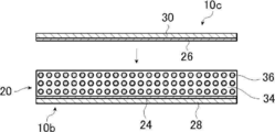
- FIG. 1 conceptually shows an example of the piezoelectric film of the present invention having the polymer composite piezoelectric material of the present invention by a cross-sectional view.
- the piezoelectric film 10 is laminated on a piezoelectric layer 20 which is a sheet-like material having piezoelectricity, a lower electrode 24 laminated on one surface of the piezoelectric layer 20, and a lower electrode 24. It has a lower protective layer 28, an upper electrode 26 laminated on the other surface of the piezoelectric layer 20, and an upper protective layer 30 laminated on the upper electrode 26.
- the piezoelectric layer 20 is formed by dispersing the piezoelectric particles 36 in a matrix 34 containing a polymer material.
- the piezoelectric layer 20 is the polymer composite piezoelectric material in the present invention. Further, the lower electrode 24 and the upper electrode 26 are the electrode layers in the present invention. Further, the lower protective layer 28 and the upper protective layer 30 are protective layers in the present invention. As will be described later, the piezoelectric film 10 (piezoelectric layer 20) is preferably polarized in the thickness direction.
- Such a piezoelectric film 10 is, for example, Various sensors such as sound sensor, ultrasonic sensor, pressure sensor, tactile sensor, distortion sensor and vibration sensor, Acoustic devices such as microphones, pickups, speakers and exciters (specifically, noise cancellers (used for cars, trains, airplanes, robots, etc.), artificial voice bands, buzzers to prevent pests and beasts from entering, furniture, wallpapers, etc. Photos, helmets, goggles, signage, robots, etc.), Haptics used for automobiles, smartphones, smart watches, games, etc. Ultrasonic transducers and ultrasonic transducers such as hydrophones, actuators used for water droplet adhesion prevention, transportation, stirring, dispersion, polishing, etc.
- Damping materials used for sports equipment such as containers, vehicles, buildings, skis and rackets, and It can be suitably used as a vibration power generator used by applying it to roads, floors, mattresses, chairs, shoes, tires, wheels, personal computer keyboards, and the like.
- the piezoelectric layer 20 which is the polymer composite piezoelectric material of the present invention, is formed by dispersing the piezoelectric particles 36 in the matrix 34.
- the polymer composite piezoelectric body, the pore volume which is cut out a sample determined by mercury porosimetry is 0.01 ⁇ L / mm 2 ⁇ 1.7 ⁇ L / mm 2. This point will be described in detail later.
- the material of the matrix 34 (matrix and binder) of the polymer composite piezoelectric material constituting the piezoelectric layer 20 it is preferable to use a polymer material having viscoelasticity at room temperature.
- the piezoelectric film 10 of the present invention is suitably used for a speaker having flexibility such as a speaker for a flexible display.
- the polymer composite piezoelectric body (piezoelectric layer 20) used for the flexible speaker has the following requirements. Therefore, it is preferable to use a polymer material having viscoelasticity at room temperature as a material satisfying the following requirements.
- "normal temperature” refers to a temperature range of about 0 to 50 ° C.
- (Ii) Sound quality A speaker vibrates piezoelectric particles at a frequency in the audio band of 20 Hz to 20 kHz, and the vibration energy causes the entire polymer composite piezoelectric body (piezoelectric film) to vibrate as a unit to reproduce sound. To. Therefore, in order to increase the transmission efficiency of vibration energy, the polymer composite piezoelectric material is required to have an appropriate hardness. Further, if the frequency characteristic of the speaker is smooth, the amount of change in sound quality when the minimum resonance frequency changes with the change in curvature also becomes small. Therefore, the loss tangent of the polymer composite piezoelectric material is required to be moderately large.
- the polymer composite piezoelectric material is required to behave hard against vibrations of 20 Hz to 20 kHz and soft against vibrations of several Hz or less. Further, the loss tangent of the polymer composite piezoelectric body is required to be appropriately large with respect to vibrations of all frequencies of 20 kHz or less.
- polymer solids have a viscoelastic relaxation mechanism, and large-scale molecular motion decreases (Relaxation) or maximizes loss elastic modulus (absorption) as the temperature rises or the frequency decreases.
- Relaxation large-scale molecular motion decreases
- absorption loss elastic modulus
- main dispersion the relaxation caused by the micro-Brownian motion of the molecular chain in the amorphous region is called main dispersion, and a very large relaxation phenomenon is observed.
- the temperature at which this main dispersion occurs is the glass transition point (Tg), and the viscoelastic relaxation mechanism appears most prominently.
- the polymer composite piezoelectric body (piezoelectric layer 20), by using a polymer material having a glass transition point at room temperature, in other words, a polymer material having viscoelasticity at room temperature, for vibration of 20 Hz to 20 kHz.
- a polymer composite piezoelectric material that is hard and behaves softly against slow vibrations of several Hz or less is realized.
- the polymer material having viscoelasticity at room temperature various known materials can be used as long as they have dielectric properties.
- a polymer material having a maximum loss tangent value of 0.5 or more at a frequency of 1 Hz by a dynamic viscoelasticity test at room temperature, that is, 0 ° C. to 50 ° C. is used.
- the polymer material preferably has a storage elastic modulus (E') at a frequency of 1 Hz measured by dynamic viscoelasticity measurement of 100 MPa or more at 0 ° C. and 10 MPa or less at 50 ° C.
- E' storage elastic modulus
- the polymer material has a relative permittivity of 10 or more at 25 ° C.
- a voltage is applied to the polymer composite piezoelectric body, a higher electric field is applied to the piezoelectric particles in the matrix, so that a large amount of deformation can be expected.
- the polymer material has a relative permittivity of 10 or less at 25 ° C.
- polymer material satisfying such conditions examples include cyanoethylated polyvinyl alcohol (cyanoethylated PVA), polyvinyl acetate, polyvinylidene chloride core acrylonitrile, polystyrene-vinyl polyisoprene block copolymer, polyvinyl methyl ketone, and polybutyl. Examples include methacrylate. Further, as these polymer materials, commercially available products such as Hybler 5127 (manufactured by Kuraray Co., Ltd.) can also be preferably used.
- Hybler 5127 manufactured by Kuraray Co., Ltd.
- the polymer material it is preferable to use a material having a cyanoethyl group, and it is particularly preferable to use cyanoethylated PVA.
- a material having a cyanoethyl group it is preferable to use cyanoethylated PVA.
- only one kind of these polymer materials may be used, and a plurality of kinds may be used in combination (mixing).
- a plurality of polymer materials may be used in combination, if necessary. That is, in addition to the polymer material having viscoelasticity at room temperature, other dielectric polymer materials may be added to the matrix 34 for the purpose of adjusting the dielectric properties and mechanical properties. ..
- dielectric polymer material examples include polyvinylidene fluoride, vinylidene fluoride-tetrafluoroethylene copolymer, vinylidene fluoride-trifluoroethylene copolymer, and polyvinylidene fluoride-trifluoroethylene copolymer.
- fluoropolymers such as polyvinylidene fluoride-tetrafluoroethylene copolymer, vinylidene cyanide-vinyl acetate copolymer, cyanoethyl cellulose, cyanoethyl hydroxysaccharose, cyanoethyl hydroxycellulose, cyanoethyl hydroxypurrane, cyanoethyl methacrylate, cyanoethyl acrylate, cyanoethyl.
- Cyano groups such as hydroxyethyl cellulose, cyanoethyl amylose, cyanoethyl hydroxypropyl cellulose, cyanoethyl dihydroxypropyl cellulose, cyanoethyl hydroxypropyl amylose, cyanoethyl polyacrylamide, cyanoethyl polyacrylate, cyanoethyl pullulan, cyanoethyl polyhydroxymethylene, cyanoethyl glycidol pullulan, cyanoethyl saccharose and cyanoethyl sorbitol.
- polymers having a cyanoethyl group synthetic rubbers such as nitrile rubber and chloroprene rubber, and the like are exemplified. Among them, a polymer material having a cyanoethyl group is preferably used. Further, in the matrix 34 of the piezoelectric layer 20, the dielectric polymer material added in addition to the polymer material having viscoelasticity at room temperature such as cyanoethylated PVA is not limited to one type, and a plurality of types are added. You may.
- the matrix 34 contains a thermoplastic resin such as vinyl chloride resin, polyethylene, polystyrene, methacrylic resin, polybutene, and isobutylene, and phenol for the purpose of adjusting the glass transition point.
- a resin, a urea resin, a melamine resin, an alkyd resin, and a thermosetting resin such as mica may be added.
- a tackifier such as rosin ester, rosin, terpene, terpene phenol, and petroleum resin may be added.
- the amount to be added when a material other than the viscoelastic polymer material such as cyanoethylated PVA is added is not particularly limited, but is 30% by mass or less in proportion to the matrix 34. Is preferable. As a result, the characteristics of the polymer material to be added can be exhibited without impairing the viscoelastic relaxation mechanism in the matrix 34, so that the dielectric constant can be increased, the heat resistance can be improved, and the adhesion to the piezoelectric particles 36 and the electrode layer can be improved. In this respect, favorable results can be obtained.
- the piezoelectric layer 20 is a polymer composite piezoelectric body in which the piezoelectric particles 36 are dispersed in such a matrix 34.
- the piezoelectric particles 36 are made of ceramic particles having a perovskite-type or wurtzite-type crystal structure. Examples of the ceramic particles constituting the piezoelectric particles 36 include lead zirconate titanate (PZT), lead zirconate titanate (PLZT), barium titanate (BaTIO 3 ), zinc oxide (ZnO), and zinc oxide (ZnO). Examples thereof include a solid solution (BFBT) of barium titanate and bismuth ferrite (BiFe 3 ). Only one type of these piezoelectric particles 36 may be used, or a plurality of types may be used in combination (mixed).
- the particle size of the piezoelectric particles 36 is not limited, and may be appropriately selected depending on the size and application of the polymer composite piezoelectric body (piezoelectric film 10).
- the particle size of the piezoelectric particles 36 is preferably 1 to 10 ⁇ m. By setting the particle size of the piezoelectric particles 36 in this range, it is possible to obtain preferable results in that the polymer composite piezoelectric body (piezoelectric film 10) can achieve both high piezoelectric characteristics and flexibility.
- the piezoelectric particles 36 in the piezoelectric layer 20 are uniformly and regularly dispersed in the matrix 34, but the present invention is not limited to this. That is, the piezoelectric particles 36 in the piezoelectric layer 20 may be irregularly dispersed in the matrix 34 as long as they are preferably uniformly dispersed.
- the amount ratio of the matrix 34 and the piezoelectric particles 36 in the piezoelectric layer 20 is not limited, and the size and thickness of the piezoelectric layer 20 in the plane direction are not limited.
- the suitable setting may be made according to the application of the polymer composite piezoelectric body and the characteristics required for the polymer composite piezoelectric body.
- the volume fraction of the piezoelectric particles 36 in the piezoelectric layer 20 is preferably 30 to 80%, more preferably 50% or more, and therefore more preferably 50 to 80%.
- the thickness of the piezoelectric layer 20 is not limited, and may be appropriately set according to the application of the polymer composite piezoelectric body, the characteristics required for the polymer composite piezoelectric body, and the like.
- the thickness of the piezoelectric layer 20 is preferably 10 to 300 ⁇ m, more preferably 20 to 200 ⁇ m, and even more preferably 30 to 150 ⁇ m.
- the piezoelectric film 10 of the illustrated example has a lower electrode 24 on one surface of the piezoelectric layer 20, a lower protective layer 28 on the surface thereof, and a lower protective layer 28 on the other surface of the piezoelectric layer 20.
- the upper electrode 26 is provided, and the upper protective layer 30 is provided on the surface thereof.
- the upper electrode 26 and the lower electrode 24 form an electrode pair.
- the piezoelectric film 10 has, for example, an upper electrode 26 and an electrode drawing portion for drawing out the electrode from the lower electrode 24, and the electrode drawing portion is connected to a power source.
- the piezoelectric film 10 may have an insulating layer or the like that covers a region where the piezoelectric layer 20 is exposed to prevent a short circuit or the like.
- the piezoelectric film 10 has a structure in which both sides of the piezoelectric layer 20 are sandwiched between electrode pairs, that is, the upper electrode 26 and the lower electrode 24, and the laminate is sandwiched between the lower protective layer 28 and the upper protective layer 30. Has. As described above, in the piezoelectric film 10, the region held by the upper electrode 26 and the lower electrode 24 is expanded and contracted according to the applied voltage.
- the lower protective layer 28 and the upper protective layer 30 are provided as a preferred embodiment rather than an essential constituent requirement.
- the lower protective layer 28 and the upper protective layer 30 cover the upper electrode 26 and the lower electrode 24, and play a role of imparting appropriate rigidity and mechanical strength to the piezoelectric layer 20. That is, in the piezoelectric film 10, the piezoelectric layer 20 composed of the matrix 34 and the piezoelectric particles 36 exhibits extremely excellent flexibility against slow bending deformation, while being rigid depending on the application. And mechanical strength may be insufficient.
- the piezoelectric film 10 is provided with a lower protective layer 28 and an upper protective layer 30 to supplement the piezoelectric film 10.
- the lower protective layer 28 and the upper protective layer 30 are not limited, and various sheet-like materials can be used, and various resin films are preferably exemplified as an example.
- various resin films are preferably exemplified as an example.
- PET polyethylene terephthalate
- PP polypropylene
- PS polystyrene
- PC polycarbonate
- PPS polyphenylene sulfide
- PMMA polymethylmethacrylate
- PET polyethylene terephthalate
- PET polypropylene
- PS polystyrene
- PC polycarbonate
- PPS polyphenylene sulfide
- PMMA polymethylmethacrylate
- PEI Polyetherimide
- PI Polystyrene
- PEN Polyethylene Naphthalate
- TAC Triacetyl Cellulose
- a resin film made of a cyclic olefin resin or the like are preferably used.
- the thickness of the lower protective layer 28 and the upper protective layer 30 there is also no limitation on the thickness of the lower protective layer 28 and the upper protective layer 30. Further, the thicknesses of the lower protective layer 28 and the upper protective layer 30 are basically the same, but may be different. Here, if the rigidity of the lower protective layer 28 and the upper protective layer 30 is too high, not only the expansion and contraction of the piezoelectric layer 20 is restricted, but also the flexibility is impaired. Therefore, the thinner the lower protective layer 28 and the upper protective layer 30, the more advantageous it is, except when mechanical strength and good handleability as a sheet-like material are required.
- the thickness of the lower protective layer 28 and the upper protective layer 30 is twice or less the thickness of the piezoelectric layer 20, it is possible to ensure both rigidity and appropriate flexibility. Preferred results can be obtained.
- the thickness of the piezoelectric layer 20 is 50 ⁇ m and the lower protective layer 28 and the upper protective layer 30 are made of PET
- the thickness of the lower protective layer 28 and the upper protective layer 30 is preferably 100 ⁇ m or less, more preferably 50 ⁇ m or less. It is preferable, and more preferably 25 ⁇ m or less.
- a lower electrode 24 is formed between the piezoelectric layer 20 and the lower protective layer 28, and an upper electrode 26 is formed between the piezoelectric layer 20 and the upper protective layer 30.
- the lower electrode 24 and the upper electrode 26 are provided to apply a driving voltage to the piezoelectric layer 20.
- the materials for forming the lower electrode 24 and the upper electrode 26 are not limited, and various conductors can be used. Specifically, alloys such as carbon, palladium, iron, tin, aluminum, nickel, platinum, gold, silver, copper, titanium, chromium and molybdenum, laminates and composites of these metals and alloys, and Examples thereof include indium tin oxide. Among them, copper, aluminum, gold, silver, platinum, and indium tin oxide are preferably exemplified as the lower electrode 24 and the upper electrode 26.
- a vapor phase deposition method such as vacuum deposition and sputtering, a film formation by plating, and a foil formed of the above materials
- Various known methods such as a method of sticking can be used.
- thin films such as copper and aluminum formed by vacuum vapor deposition are preferably used as the lower electrode 24 and the upper electrode 26 because the flexibility of the piezoelectric film 10 can be ensured.
- a copper thin film produced by vacuum deposition is preferably used.
- the thickness of the lower electrode 24 and the upper electrode 26 There is no limitation on the thickness of the lower electrode 24 and the upper electrode 26. Further, the thicknesses of the lower electrode 24 and the upper electrode 26 are basically the same, but may be different.
- the lower electrode 24 and the upper electrode 26 are thinner as long as the electric resistance does not become too high. That is, the lower electrode 24 and the upper electrode 26 are preferably thin film electrodes.
- the flexibility is increased. It is suitable because it does not damage it.
- the lower protective layer 28 and the upper protective layer 30 are made of PET (Young's modulus: about 6.2 GPa) and the lower electrode 24 and the upper electrode 26 are made of copper (Young's modulus: about 130 GPa)
- the lower protective layer 28 Assuming that the thickness of the upper protective layer 30 is 25 ⁇ m, the thickness of the lower electrode 24 and the upper electrode 26 is preferably 1.2 ⁇ m or less, more preferably 0.3 ⁇ m or less, and particularly preferably 0.1 ⁇ m or less.
- the piezoelectric film 10 preferably has a maximum value of loss tangent (Tan ⁇ ) at a frequency of 1 Hz as measured by dynamic viscoelasticity measurement at room temperature, and more preferably has a maximum value of 0.1 or more at room temperature.
- Tan ⁇ loss tangent
- the piezoelectric film 10 preferably has a storage elastic modulus (E') at a frequency of 1 Hz measured by dynamic viscoelasticity measurement of 10 GPa to 30 GPa at 0 ° C. and 1 GPa to 10 GPa at 50 ° C. Regarding this condition, the same applies to the piezoelectric layer 20. As a result, the piezoelectric film 10 can have a large frequency dispersion in the storage elastic modulus (E'). That is, it can behave hard for vibrations of 20 Hz to 20 kHz and soft for vibrations of several Hz or less.
- E' storage elastic modulus
- the product of the thickness and the storage elastic modulus at a frequency of 1 Hz measured by dynamic viscoelasticity is 1.0 ⁇ 10 5 to 2.0 ⁇ 10 6 (1.0E + 05 to 2.) At 0 ° C. It is preferably 0E + 06) N / m, preferably 1.0 ⁇ 10 5 to 1.0 ⁇ 10 6 (1.0E + 05 to 1.0E + 06) N / m at 50 ° C. Regarding this condition, the same applies to the piezoelectric layer 20. As a result, the piezoelectric film 10 can be provided with appropriate rigidity and mechanical strength as long as the flexibility and acoustic characteristics are not impaired.
- the piezoelectric film 10 preferably has a loss tangent of 0.05 or more at 25 ° C. and a frequency of 1 kHz in the master curve obtained from the dynamic viscoelasticity measurement. Regarding this condition, the same applies to the piezoelectric layer 20. As a result, the frequency characteristics of the speaker using the piezoelectric film 10 are smoothed, and the change in sound quality when the minimum resonance frequency f 0 changes with the change in the curvature of the speaker can be reduced.
- the storage elastic modulus (Young's modulus) and the loss tangent of the piezoelectric film 10 and the piezoelectric layer 20 and the like may be measured by a known method.
- the measurement may be performed using a dynamic viscoelasticity measuring device DMS6100 manufactured by SII Nanotechnology Inc. (manufactured by SII Nanotechnology Inc.).
- the measurement frequency is 0.1 Hz to 20 Hz (0.1 Hz, 0.2 Hz, 0.5 Hz, 1 Hz, 2 Hz, 5 Hz, 10 Hz and 20 Hz)
- the measurement temperature is -50 to 150 ° C.
- the temperature rise rate is 2 ° C./min (in a nitrogen atmosphere)
- the sample size is 40 mm ⁇ 10 mm (including the clamp region)
- the inter-chuck distance is 20 mm.
- the pore volume measured by mercury porosimetry a unit sectional area per 0.01 ⁇ L / mm 2 ⁇ 1.7 ⁇ L / mm 2.
- the pore volume per unit area measured by the mercury intrusion method in the cross section of the polymer composite piezoelectric body is the thickness direction of the piezoelectric film. It is a value obtained by measuring the press-fitting amount of mercury by a mercury press-fitting method and dividing the press-fitting amount by the cross-sectional area of the polymer composite piezoelectric body of the sample.
- the electrode layers are laminated on both main surfaces of the polymer composite piezoelectric body, so that both main surfaces are sealed by the electrode layers. Therefore, the amount of mercury injected by the mercury injection method is the amount of mercury injected into the polymer composite piezoelectric body in the cross section of the sample.
- the relative permittivity of the polymer material becomes maximum near the glass transition point. Therefore, for example, when the humidity of the atmosphere becomes high, more water is adsorbed on the polymer composite piezoelectric body, and the glass transition point of the polymer material as a matrix is lowered. Along with this, apparently, for example, the relative permittivity of the polymer material at room temperature increases.
- the relative permittivity of the polymer material is increased, a higher electric field is applied to the piezoelectric particles in the matrix when a voltage is applied to the polymer composite piezoelectric body, so that the piezoelectric particles in the matrix can be deformed more greatly. That is, the piezoelectric conversion efficiency of the piezoelectric film is increased.
- the piezoelectric conversion efficiency of the piezoelectric film changes due to the adsorption of moisture on the polymer composite piezoelectric body.
- the sound pressure changes depending on the humidity of the atmosphere.
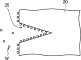
- the end face of the polymer composite piezoelectric material has recesses (pores), and the influence of the humidity of the atmosphere depends on the size and number of the pores. I found it different. Specifically, as shown in FIG. 2, when the end face of the polymer composite piezoelectric body (piezoelectric layer 20) has pores 35, the actual surface area of the end face of the polymer composite piezoelectric body, that is, is exposed to the outside. Since the area (the area of the interface with the atmosphere) is large, the amount of water W adsorbed increases.
- the humidity of the atmosphere is low and the actual surface area of the end face of the polymer composite piezoelectric body, that is, the area of the interface with the atmosphere is large, the moisture in the polymer composite piezoelectric body is likely to evaporate. Therefore, the larger the actual surface area of the end face of the polymer composite piezoelectric body, the easier it is for the water W to be adsorbed and evaporated, and the change in the piezoelectric conversion efficiency of the piezoelectric film due to the change in the water content is likely to occur.
- the piezoelectric film of the present invention is a polymer composite piezoelectric material by setting the pore volume per unit area of the polymer composite piezoelectric body to 0.01 ⁇ L / mm 2 to 1.7 ⁇ L / mm 2 .
- a piezoelectric film is used as a piezoelectric film for various purposes after forming each layer such as an electrode layer and a polymer composite piezoelectric body and then cutting it into a desired shape. Therefore, on the end surface of the polymer composite piezoelectric body of the piezoelectric film after cutting, the bubble portion on the cut surface appears as a recess (pore).
- the present invention is such that due to the bubbles, and 0.01 ⁇ L / mm 2 ⁇ 1.7 ⁇ L / mm 2 per unit area of the volume of the pores of the end face of the polymer composite piezoelectric body.
- the pore volume per unit area of the polymer composite piezoelectric material is measured using a cut-out sample.
- the polymer is polymer.
- the pore volume per unit area on the end face of the composite piezoelectric material is basically the same as the pore volume per unit area measured using a sample.
- the pore volume per unit area of the polymer composite piezoelectric body is it is preferably from 0.05 ⁇ L / mm 2 ⁇ 1.7 ⁇ L / mm 2, more preferably from 0.05 ⁇ L / mm 2 ⁇ 0.6 ⁇ L / mm 2, 0.05 ⁇ L / mm 2 ⁇ 0.3 ⁇ L / It is more preferably mm 2 .
- the volume of the bubbles corresponds to the pore volume per unit area of the polymer composite piezoelectric body. Since the bubbles in the polymer composite piezoelectric body act as a path for water, if the volume of the bubbles is large, the water adhering to the polymer composite piezoelectric body is more likely to enter the polymer composite piezoelectric body.
- the present invention is that the 0.01 ⁇ L / mm 2 ⁇ 1.7 ⁇ L / mm 2 the pore volume per unit area of the polymer composite piezoelectric body, the volume of the bubble of the polymer composite piezoelectric body Can also be reduced to prevent water from entering the polymer composite piezoelectric body.
- a sample is cut out from the piezoelectric film.
- the sample shall be a piezoelectric film cut in the thickness direction and cut out to a size of 12.5 mm ⁇ 25 mm.
- the piezoelectric film has a layer other than the electrode layer such as a protective layer, it is assumed that the piezoelectric film has a protective layer from the sample. That is, the sample is assumed to have electrode layers on both sides of the polymer composite piezoelectric body.
- the cut out samples are weighed and the number of samples is adjusted so that the total mass of the samples is 1.2 g to 1.5 g. In addition, the sample is not pretreated for vacuum exhaust.
- the above sample is placed in a cell container of the pore distribution measuring device Autopore IV 9520 manufactured by Shimadzu Corporation-Micromeritics Co., Ltd., and the amount of mercury press-fitted is measured.
- a cell a 5 cc large piece cell (stem volume 0.4 cc) is used.
- the measurement pressure is such that the initial pressure is about 7 kPa (1.0 psia (corresponding to the pore diameter of about 180 ⁇ m)) and the maximum pressure is about 400 MPa (60,000 psia). In this pressure range, for example, the pressure is applied in a plurality of times under the conditions shown in FIG.
- the analysis software uses AutoPore IV 9500 version 1.09.
- the physical property values of mercury used in the calculation are set to a mercury contact angle of 130.0 degrees and a mercury surface tension of 485.0 days / cm. There is no blank correction.
- the pore distribution is measured under the above conditions.
- the amount of mercury intrusion is calculated as follows.
- the amount of mercury injected is calculated in the range of pore diameter of 0.1 ⁇ m to 10 ⁇ m. That is, the mercury intrusion amount (unit: ⁇ L / g) per 1 g of the sample is the integrated value of the mercury intrusion amount in the pore diameter of 10 ⁇ m (pressure of about 17 psia) from the integrated value of the mercury intrusion amount in the pore diameter of 0.1 ⁇ m (pressure of about 1700 psia). Obtained by subtracting.
- the amount of mercury injected per 1 g of the obtained sample ( ⁇ L / g) is multiplied by the mass of the sample to determine the amount of mercury injected ( ⁇ L).
- the total exposed area of the polymer composite piezoelectric material that is, the total cross-sectional area in the sample for which the amount of mercury intrusion has been determined is calculated as follows.
- the method for measuring the thickness of the polymer composite piezoelectric layer in the cross section of the polymer composite piezoelectric body is as follows. Cut in the thickness direction to observe the cross section of the polymer composite piezoelectric body.
- a Leica Biosystem RM2265 is attached with a Drukker histo knife blade width of 8 mm, and the speed is set to the controller scale 1 and the meshing amount is set to 0.25 ⁇ m to 1 ⁇ m to obtain a cross section.
- the cross section is observed with a scanning electron microscope (SEM) (for example, SU8220 manufactured by Hitachi High-Technologies Corporation).
- SEM scanning electron microscope
- the sample is conductively treated by Pt vapor deposition, and the work distance is 3 mm.
- the observation conditions are SE image (Upper), acceleration voltage: 0.5 kV, sharp image is output by focus adjustment and astigmatism adjustment, and automatic brightness adjustment (auto) with the polymer composite piezoelectric part covering the entire screen. Set Brightness: 0, Contrast: 0).
- the magnification of photography is such that the electrodes at both ends fit on one screen and the width between the electrodes is more than half of the screen.
- the length between the two electrode layers laminated on both sides of the polymer composite piezoelectric body is obtained and used as the thickness of the polymer composite piezoelectric body. This is performed in any 10 cross sections, and the average value of the distances between the electrodes is taken as the thickness of the polymer composite piezoelectric layer. Multiply the obtained thickness of the polymer composite piezoelectric layer by the total width of the polymer composite piezoelectrics in the sample cross section, that is, "(12.5 mm + 25 mm) x 2 x number of samples" to obtain the polymer composite piezoelectric layer. Calculate the total exposed area (cross-sectional area) of.
- the pore volume per unit area may be obtained in the same manner as described above by using a sample cut out by masking both main surfaces of the polymer composite piezoelectric body.
- Masking of both main surfaces of the polymer composite piezoelectric body is preferably performed with a metal layer used as an electrode layer such as a copper foil. That is, it is preferable that the sample form is the same as that of the sample in the case of the piezoelectric film, and the pore volume per unit area is obtained even in the case of the polymer composite piezoelectric body alone.
- a method of adjusting the pore volume per unit area of the polymer composite piezoelectric material for example, by performing a line mixing treatment before applying the paint, air bubbles in the paint are made finer by shearing force, and the surface before drying is performed. There is a method of eliminating air bubbles that cause pores by making it easier to escape from.
- the processing time (processing length) and the number of rotations of the lymixing the size of bubbles in the paint can be adjusted, and the amount of bubbles that escape during drying can be adjusted.
- the processing time and rotation speed of line mixing depend on the desired pore volume, matrix type, solvent (the substance) type, solvent ratio, paint viscosity, and the thickness of the polymer composite piezoelectric material to be formed. It may be set as appropriate according to the situation.
- a sheet-like object 10a in which the lower electrode 24 is formed on the lower protective layer 28 is prepared.
- the sheet-like material 10a may be produced by forming a copper thin film or the like as the lower electrode 24 on the surface of the lower protective layer 28 by vacuum deposition, sputtering, plating or the like.
- the lower protective layer 28 with a separator temporary support
- PET or the like having a thickness of 25 ⁇ m to 100 ⁇ m can be used.
- the separator may be removed after thermocompression bonding the upper electrode 26 and the upper protective layer 30 and before laminating any member on the lower protective layer 28.
- a polymer material to be a matrix material is dissolved in an organic solvent, and piezoelectric particles 36 such as PZT particles are added and stirred to prepare a dispersed coating material.
- organic solvent there are no restrictions on the organic solvent other than the above substances, and various organic solvents can be used.
- a line mixing process is performed before applying the prepared paint.
- the air bubbles in the coating material are made finer and easily removed from the surface before drying, so that the pore area of the produced polymer composite piezoelectric material can be reduced.
- the paint is cast (applied) to the sheet-like material 10a to evaporate the organic solvent and dry it.
- a laminated body 10b having the lower electrode 24 on the lower protective layer 28 and forming the piezoelectric layer 20 on the lower electrode 24 is produced.
- the lower electrode 24 is an electrode on the base material side when the piezoelectric layer 20 is applied, and does not indicate the vertical positional relationship in the laminated body.
- a dielectric polymer material may be added to the matrix 34 in addition to the viscoelastic material such as cyanoethylated PVA.
- the polymer materials to be added to the paint described above may be dissolved.
- the polarization treatment (polling) of the piezoelectric layer 20 is preferably performed. Do.
- the method for polarization treatment of the piezoelectric layer 20 is not limited, and known methods can be used.
- a calendar treatment may be performed in which the surface of the piezoelectric layer 20 is smoothed by using a heating roller or the like. By performing this calendar processing, the thermocompression bonding process described later can be smoothly performed.
- a sheet-like material 10c in which the upper electrode 26 is formed on the upper protective layer 30 is prepared.
- the sheet-like material 10c may be produced by forming a copper thin film or the like as the upper electrode 26 on the surface of the upper protective layer 30 by vacuum deposition, sputtering, plating or the like.
- the upper electrode 26 is directed toward the piezoelectric layer 20, and the sheet-like material 10c is laminated on the laminated body 10b that has undergone the polarization treatment of the piezoelectric layer 20.
- the laminate 10b and the sheet-like material 10c are thermocompression-bonded with a heating press device or a heating roller or the like so as to sandwich the upper protective layer 30 and the lower protective layer 28, and then have a desired shape.
- the piezoelectric film 10 is produced by cutting into.
- the laminated piezoelectric element 14 described later has a configuration in which such a piezoelectric film 10 of the present invention is laminated and bonded with a sticking layer 19 as a preferred embodiment.
- the laminated piezoelectric element 14 shown in FIG. 7 has the polarization directions of the adjacent piezoelectric films 10 opposite to each other, as shown by the arrows attached to the piezoelectric layer 20.
- a general laminated ceramic piezoelectric element in which piezoelectric ceramics are laminated is subjected to a polarization treatment after producing a laminate of piezoelectric ceramics. Since only common electrodes exist at the interface of each piezoelectric layer, the polarization directions of each piezoelectric layer alternate in the stacking direction.
- the polarization treatment can be performed in the state of the piezoelectric film 10 before lamination.
- the piezoelectric film 10 preferably undergoes a polarization treatment of the piezoelectric layer 20 before laminating the upper electrode 26 and the upper protective layer 30. Therefore, the laminated piezoelectric element using the piezoelectric film of the present invention can be produced by laminating the polarization-treated piezoelectric film 10.
- a long piezoelectric film (large-area piezoelectric film) subjected to polarization treatment is produced, cut into individual piezoelectric films 10, and then the piezoelectric films 10 are laminated to form a laminated piezoelectric element 14. Therefore, in the laminated piezoelectric element using the piezoelectric film of the present invention, the polarization directions of the adjacent piezoelectric films 10 can be aligned in the laminated direction as in the laminated piezoelectric element 60 shown in FIG. 9, and the laminated piezoelectric element shown in FIG. 7 can be aligned. Like the element 14, it can be alternated.
- a general piezoelectric film made of a polymer material such as PVDF (polyvinylidene fluoride) the molecular chains are oriented in the stretching direction by stretching in the uniaxial direction after the polarization treatment, and as a result, the molecular chains are oriented in the stretching direction. It is known that large piezoelectric properties can be obtained. Therefore, a general piezoelectric film has in-plane anisotropy in the piezoelectric characteristics, and has anisotropy in the amount of expansion and contraction in the plane direction when a voltage is applied.
- PVDF polyvinylidene fluoride
- the polymer composite piezoelectric material of the present invention in which the piezoelectric particles 36 are dispersed in the matrix 34 can obtain large piezoelectric characteristics without stretching treatment after polarization treatment. Therefore, the polymer composite piezoelectric material of the present invention has no in-plane anisotropy in the piezoelectric characteristics, and when a driving voltage is applied as described later, it expands and contracts isotropically in all directions in the in-plane direction.
- the polymer composite piezoelectric body and the piezoelectric film 10 of the present invention may be produced by using a cut sheet-like sheet, but preferably roll-to-roll or less. , Also called RtoR).
- RtoR is a raw material that has been processed by drawing out the raw material from a roll formed by winding a long raw material and carrying it in the longitudinal direction while performing various treatments such as film formation and surface treatment. This is a manufacturing method in which the material is wound into a roll again.
- a second roll formed by winding a sheet-like material 10c having an upper electrode 26 formed on a long upper protective layer 30 is used.
- the first roll and the second roll may be exactly the same.
- a sheet-like material 10a is pulled out from this roll, and while being conveyed in the longitudinal direction, a paint containing the matrix 34 and the piezoelectric particles 36 is applied, dried by heating or the like, and the piezoelectric layer is placed on the lower electrode 24. 20 is formed to form the above-mentioned laminated body 10b.
- the above-mentioned polarization treatment is performed to perform the polarization treatment of the piezoelectric layer 20.
- the piezoelectric film 10 is manufactured by RtoR
- the piezoelectric layer 20 is polarized while the laminated body 10b is conveyed.
- calendar processing may be performed before this polarization treatment.
- the sheet-like material 10c is pulled out from the second roll, and while the sheet-like material 10c and the laminated body are conveyed, the upper electrode 26 is subjected to the piezoelectric layer as described above by a known method using a bonding roller or the like.
- the sheet-like material 10c is laminated on the laminated body 10b toward 20.
- the laminated laminate 10b and the sheet-like material 10c are thermocompression-bonded by sandwiching and transporting them by a pair of heating rollers to complete the piezoelectric film 10 of the present invention, and the piezoelectric film 10 is wound in a roll shape. To do.
- the piezoelectric film 10 of the present invention is produced by transporting the sheet-like material (laminated body) only once in the longitudinal direction by RtoR, but the present invention is not limited to this.
- the laminated body roll is made by winding the laminated body once in a roll shape.
- the laminate is pulled out from the laminate roll, and while being conveyed in the longitudinal direction, the sheet-like material having the upper electrode 26 formed on the upper protective layer 30 is laminated as described above to form a piezoelectric film. 10 may be completed, and the piezoelectric film 10 may be wound in a roll shape.
- the piezoelectric film 10 when a voltage is applied to the lower electrode 24 and the upper electrode 26, the piezoelectric particles 36 expand and contract in the polarization direction according to the applied voltage. As a result, the piezoelectric film 10 (piezoelectric layer 20) shrinks in the thickness direction. At the same time, the piezoelectric film 10 expands and contracts in the in-plane direction due to the pore ratio. This expansion and contraction is about 0.01 to 0.1%. As described above, it expands and contracts isotropically in all directions in the in-plane direction. As described above, the thickness of the piezoelectric layer 20 is preferably about 10 to 300 ⁇ m. Therefore, the expansion and contraction in the thickness direction is very small, about 0.3 ⁇ m at the maximum.
- the piezoelectric film 10 that is, the piezoelectric layer 20, has a size much larger than the thickness in the plane direction. Therefore, for example, if the length of the piezoelectric film 10 is 20 cm, the piezoelectric film 10 expands and contracts by a maximum of about 0.2 mm when a voltage is applied. Further, when pressure is applied to the piezoelectric film 10, electric power is generated by the action of the piezoelectric particles 36. By utilizing this, the piezoelectric film 10 can be used for various purposes such as a speaker, a microphone, and a pressure-sensitive sensor as described above.
- FIG. 6 shows a conceptual diagram of an example of a flat plate type piezoelectric speaker having the piezoelectric film 10 of the present invention.
- the piezoelectric speaker 45 is a flat plate type piezoelectric speaker that uses the piezoelectric film 10 of the present invention as a diaphragm that converts an electric signal into vibration energy.
- the piezoelectric speaker 45 can also be used as a microphone, a sensor, or the like.
- the piezoelectric speaker 45 includes a piezoelectric film 10, a case 43, a viscoelastic support 46, and a frame body 48.
- the case 43 is a thin square-shaped tubular housing that is made of plastic or the like and has an open surface.
- the frame body 48 is a plate material having a through hole in the center and having the same shape as the upper end surface (open surface side) of the case 43.
- the viscoelastic support 46 has appropriate viscosity and elasticity, supports the piezoelectric film 10, and applies a constant mechanical bias to any part of the piezoelectric film to move the piezoelectric film 10 back and forth without waste. It is for converting into motion (movement in the direction perpendicular to the surface of the film).
- wool felt, non-woven fabric such as wool felt containing rayon and PET, glass wool and the like are exemplified.
- the piezoelectric speaker 45 accommodates the viscoelastic support 46 in the case 43, covers the case 43 and the viscoelastic support 46 with the piezoelectric film 10, and surrounds the periphery of the piezoelectric film 10 with the frame 48 to form the upper end surface of the case 43.
- the frame body 48 is fixed to the case 43 while being pressed against the case 43.
- the viscoelastic support 46 is a square columnar whose height (thickness) is thicker than the height of the inner surface of the case 43. Therefore, in the piezoelectric speaker 45, the viscoelastic support 46 is held in a state of being thinned by being pressed downward by the piezoelectric film 10 at the peripheral portion of the viscoelastic support 46. Similarly, in the peripheral portion of the viscoelastic support 46, the curvature of the piezoelectric film 10 suddenly fluctuates, and the piezoelectric film 10 is formed with a rising portion 45a that becomes lower toward the periphery of the viscoelastic support 46. Further, the central region of the piezoelectric film 10 is pressed by the viscoelastic support 46 having a square columnar shape to be (omitted) flat.
- the piezoelectric speaker 45 When the piezoelectric film 10 is stretched in the in-plane direction by applying a driving voltage to the lower electrode 24 and the upper electrode 26, the piezoelectric speaker 45 is made piezoelectric by the action of the viscoelastic support 46 in order to absorb the stretched portion.
- the rising portion 45a of the film 10 changes the angle in the rising direction.
- the piezoelectric film 10 having the flat portion moves upward.
- the piezoelectric film 10 contracts in the in-plane direction due to the application of the driving voltage to the lower electrode 24 and the upper electrode 26
- the rising portion 45a of the piezoelectric film 10 collapses in order to absorb the contracted portion. Change the angle in the direction closer to the plane).
- the piezoelectric film 10 having the flat portion moves downward.
- the piezoelectric speaker 45 generates sound by the vibration of the piezoelectric film 10.
- the conversion from the stretching motion to the vibration can also be achieved by holding the piezoelectric film 10 in a curved state. Therefore, the piezoelectric film 10 of the present invention can function as a flexible speaker by simply holding it in a curved state instead of such a piezoelectric speaker 45.
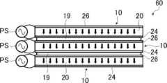
- FIG. 7 conceptually shows an example of an electroacoustic converter having the piezoelectric film 10 of the present invention.
- the electroacoustic transducer 50 shown in FIG. 7 has a laminated piezoelectric element 14 and a diaphragm 12.
- the laminated piezoelectric element 14 is formed by laminating a plurality of layers of the piezoelectric film of the present invention.
- the laminated piezoelectric element 14 is formed by laminating three layers of the above-mentioned piezoelectric film 10 of the present invention.
- the laminated piezoelectric element 14 and the diaphragm 12 are attached by an attachment layer 16.
- a power supply PS for applying a driving voltage is connected to the piezoelectric film 10 constituting the laminated piezoelectric element 14 of the electroacoustic converter 50.
- the lower protective layer 28 and the upper protective layer 30 are omitted for simplification of the drawings.
- all the piezoelectric films 10 have both the lower protective layer 28 and the upper protective layer 30.
- the laminated piezoelectric element is not limited to this, and a piezoelectric film having a protective layer and a piezoelectric film not having a protective layer may be mixed. Further, when the piezoelectric film has a protective layer, the piezoelectric film may have only the lower protective layer 28 or only the upper protective layer 30.
- the piezoelectric film in the uppermost layer in the figure has only the upper protective layer 30, and the piezoelectric film in the middle has no protective layer.
- the structure may be such that the lowermost piezoelectric film has only the lower protective layer 28.
- the piezoelectric film 10 expands and contracts in the plane direction by applying a driving voltage to the piezoelectric film 10 of the laminated piezoelectric element 14, and the expansion and contraction of the piezoelectric film 10 causes the piezoelectric film 10 to expand and contract.
- the laminated piezoelectric element 14 expands and contracts in the plane direction.
- the expansion and contraction of the laminated piezoelectric element 14 in the surface direction causes the diaphragm 12 to bend, and as a result, the diaphragm 12 vibrates in the thickness direction. Due to the vibration in the thickness direction, the diaphragm 12 generates a sound.
- the diaphragm 12 vibrates according to the magnitude of the drive voltage applied to the piezoelectric film 10, and generates a sound corresponding to the drive voltage applied to the piezoelectric film 10. That is, the electroacoustic converter 50 is a speaker that uses the laminated piezoelectric element 14 as an exciter.
- the diaphragm 12 is, in a preferred embodiment, flexible.
- having flexibility is synonymous with having flexibility in a general interpretation, and indicates that it can be bent and bent, specifically. Shows that it can be bent and stretched without causing breakage and damage.
- the diaphragm 12 is not limited as long as it is preferably flexible and satisfies the relationship with the laminated piezoelectric element 14 described later, and various sheet-like materials (plate-like materials, films) can be used. is there.
- PET polyethylene terephthalate
- PP polypropylene
- PS polystyrene
- PC polycarbonate
- PPS polyphenylene sulfide
- PMMA polymethylmethacrylate
- PEI polyetherimide
- PI polyimide
- PEN polyethylene naphthalate
- TAC triacetyl cellulose
- foamed plastic made of expanded polystyrene, expanded styrene, expanded polyethylene, etc., and other on one or both sides of wavy paperboard.
- cardboard materials and the like made by sticking the paperboard of the above are exemplified.
- the vibrating plate 12 includes an organic electroluminescence (OLED (Organic Light Emitting Diode)) display, a liquid crystal display, and a micro LED (Light Emitting Diode) display.
- OLED Organic Light Emitting Diode
- a display device such as an inorganic electroluminescent display can also be suitably used.
- such a diaphragm 12 and the laminated piezoelectric element 14 are attached by an attachment layer 16.
- the adhesive layer 16 has fluidity when bonded, and then becomes a solid. Even a layer made of an adhesive is a soft solid gel-like (rubber-like) when bonded, and then gels. It may be a layer made of a pressure-sensitive adhesive whose state does not change, or a layer made of a material having the characteristics of both an adhesive and a pressure-sensitive adhesive.
- the laminated piezoelectric element 14 is expanded and contracted to bend and vibrate the diaphragm 12 to generate sound.
- the adhesive layer 16 is preferably an adhesive layer made of an adhesive, which can obtain a solid and hard adhesive layer 16 rather than the adhesive layer made of an adhesive.
- the more preferable adhesive layer 16 include an adhesive layer made of a polyester adhesive and a thermoplastic type adhesive such as a styrene-butadiene rubber (SBR) adhesive. Adhesion, unlike adhesion, is useful when seeking high adhesion temperatures. Further, the thermoplastic type adhesive has "relatively low temperature, short time, and strong adhesion" and is suitable.
- SBR styrene-butadiene rubber
- the thickness of the sticking layer 16 is not limited, and a thickness at which sufficient sticking force (adhesive force, adhesive force) can be obtained may be appropriately set according to the material of the sticking layer 16.
- the thinner the adhesive layer 16 the higher the effect of transmitting the expansion / contraction energy (vibration energy) of the laminated piezoelectric element 14 transmitted to the diaphragm 12, and the higher the energy efficiency. ..
- the adhesive layer 16 is thick and has high rigidity, the expansion and contraction of the laminated piezoelectric element 14 may be restricted.
- the sticking layer 16 is preferably thin.
- the thickness of the sticking layer 16 is preferably 0.1 to 50 ⁇ m, more preferably 0.1 to 30 ⁇ m, and even more preferably 0.1 to 10 ⁇ m after sticking.
- the sticking layer 16 is provided as a preferred embodiment and is not an essential component. Therefore, the electroacoustic converter 50 does not have the bonding layer 16, and the diaphragm 12 and the laminated piezoelectric element 14 may be fixed by using known crimping means, fastening means, fixing means, and the like. ..
- the laminated piezoelectric element 14 is rectangular, the four corners may be fastened with members such as bolts and nuts to form an electroacoustic transducer, or the four corners and the central portion may be bolted and nuts.
- the electroacoustic converter may be formed by fastening with members.
- the laminated piezoelectric element 14 expands and contracts independently with respect to the diaphragm 12, and in some cases, only the laminated piezoelectric element 14 bends.
- the expansion and contraction of the laminated piezoelectric element 14 is not transmitted to the diaphragm 12.
- the vibration efficiency of the diaphragm 12 by the laminated piezoelectric element 14 decreases.
- the diaphragm 12 cannot be vibrated sufficiently.
- it is preferable that the diaphragm 12 and the laminated piezoelectric element 14 are attached by the attachment layer 16 as shown in FIG.
- the laminated piezoelectric element 14 has a configuration in which three piezoelectric films 10 are laminated and adjacent piezoelectric films 10 are attached by an attachment layer 19.
- a power supply PS for applying a driving voltage for expanding and contracting the piezoelectric film 10 is connected to each piezoelectric film 10.
- the laminated piezoelectric element 14 shown in FIG. 7 is formed by laminating three layers of piezoelectric films 10, but the present invention is not limited thereto. That is, as long as the laminated piezoelectric element is formed by laminating a plurality of layers of the piezoelectric film 10, the number of laminated piezoelectric films 10 may be two layers or four or more layers.
- the electroacoustic converter may be one that vibrates the diaphragm 12 with the same effect and effect by the piezoelectric film of the present invention instead of the laminated piezoelectric element 14 to generate sound. That is, the electroacoustic converter may use the piezoelectric film of the present invention as an exciter.
- the polarization directions of the adjacent piezoelectric films 10 are reversed from each other, and a plurality of layers (three layers in the example shown in FIG. 7) of the piezoelectric films 10 are laminated and adjacent to each other. It has a structure in which the piezoelectric film 10 is attached by the attachment layer 19.
- the adhesive layer 19 may be the above-mentioned layer made of an adhesive, a layer made of an adhesive, or a layer made of a material having the characteristics of both an adhesive and an adhesive.
- the laminated piezoelectric element 14 vibrates the diaphragm 12 by expanding and contracting the plurality of laminated piezoelectric films 10, and generates sound. Therefore, it is preferable that the expansion and contraction of each piezoelectric film 10 is directly transmitted to the laminated piezoelectric element 14.
- the adhesive layer 19 is preferably an adhesive layer made of an adhesive, which can obtain a solid and hard adhesive layer 19 rather than an adhesive layer made of an adhesive.
- an adhesive layer made of a polyester adhesive and a thermoplastic type adhesive such as a styrene-butadiene rubber (SBR) adhesive is preferably exemplified. Adhesion, unlike adhesion, is useful when seeking high adhesion temperatures. Further, the thermoplastic type adhesive has "relatively low temperature, short time, and strong adhesion" and is suitable.
- the thickness of the sticking layer 19 is not limited, and a thickness capable of exhibiting a sufficient sticking force may be appropriately set according to the material for forming the sticking layer 19.
- the thinner the bonding layer 19 the higher the effect of transmitting the expansion and contraction energy of the piezoelectric film 10, and the higher the energy efficiency.
- the adhesive layer 19 is thick and has high rigidity, the expansion and contraction of the piezoelectric film 10 may be restricted.
- the sticking layer 19 is preferably thinner than the piezoelectric layer 20. That is, in the laminated piezoelectric element 14, the bonding layer 19 is preferably hard and thin.
- the thickness of the sticking layer 19 is preferably 0.1 to 50 ⁇ m, more preferably 0.1 to 30 ⁇ m, and even more preferably 0.1 to 10 ⁇ m after sticking.
- the polarization directions of the adjacent piezoelectric films are opposite to each other, and there is no possibility that the adjacent piezoelectric films 10 are short-circuited, so that the bonding layer 19 can be made thin. ..
- the spring constant of the sticking layer 19 is equal to or less than the spring constant of the piezoelectric film 10.
- the product of the thickness of the adhesive layer 19 and the storage elastic modulus (E') at a frequency of 1 Hz by dynamic viscoelasticity measurement is 2.0 ⁇ 10 6 N / m or less at 0 ° C., 50. It is preferably 1.0 ⁇ 10 6 N / m or less at ° C.
- the internal loss at a frequency of 1 Hz by the dynamic viscoelasticity measurement of the adhesive layer is 1.0 or less at 25 ° C. in the case of the adhesive layer 19 made of an adhesive, and in the case of the adhesive layer 19 made of an adhesive. It is preferably 0.1 or less at 25 ° C.
- the bonding layer 19 is provided as a preferred embodiment and is not an essential component. Therefore, the laminated piezoelectric element constituting the electroacoustic converter does not have the bonding layer 19, and the piezoelectric film 10 is laminated and brought into close contact with each other by using known crimping means, fastening means, fixing means and the like.
- the laminated piezoelectric element may be configured. For example, when the piezoelectric film 10 is rectangular, the four corners may be fastened with bolts and nuts to form a laminated piezoelectric element, or the four corners and the central portion may be fastened with bolts and nuts to form a laminated piezoelectric element. May be configured.
- the laminated piezoelectric film 10 may be fixed by attaching an adhesive tape to the peripheral portion (end face) to form a laminated piezoelectric element.
- the individual piezoelectric films 10 expand and contract independently, and in some cases, each layer of each piezoelectric film 10 bends in the opposite direction to form a gap. It ends up.
- the drive efficiency of the laminated piezoelectric element decreases, the expansion and contraction of the laminated piezoelectric element as a whole becomes small, and the diaphragm and the like that come into contact with each other.
- the laminated piezoelectric element has a bonding layer 19 for bonding adjacent piezoelectric films 10 to each other, as in the laminated piezoelectric element 14 shown in FIG.
- a power supply PS is connected to the lower electrode 24 and the upper electrode 26 of each piezoelectric film 10 to apply a driving voltage for expanding and contracting the piezoelectric film 10, that is, to supply driving power.
- the power supply PS is not limited and may be a DC power supply or an AC power supply.
- the drive voltage capable of appropriately driving each piezoelectric film 10 may be appropriately set according to the thickness of the piezoelectric layer 20 of each piezoelectric film 10 and the forming material. As will be described later, in the laminated piezoelectric element 14, the polarization directions of the adjacent piezoelectric films 10 are opposite to each other.
- the lower electrodes 24 and the upper electrodes 26 face each other. Therefore, the power supply PS always supplies power of the same polarity to the facing electrodes regardless of whether it is an AC power supply or a DC power supply.
- the upper electrode 26 of the piezoelectric film 10 in the lowermost layer in the figure and the upper electrode 26 of the piezoelectric film 10 in the second layer (middle) always have the same polarity. Power is always supplied to the lower electrode 24 of the second layer piezoelectric film 10 and the lower electrode 24 of the uppermost piezoelectric film 10 in the drawing.
- the method of drawing the electrode from the lower electrode 24 and the upper electrode 26 is not limited, and various known methods can be used.
- An example is a method in which the through hole is filled with a conductive material and the electrode is pulled out to the outside.
- suitable electrode extraction methods include the methods described in JP-A-2014-209724 and the methods described in JP-A-2016-015354.
- the piezoelectric layer 20 is formed by dispersing the piezoelectric particles 36 in the matrix 34. Further, the lower electrode 24 and the upper electrode 26 are provided so as to sandwich the piezoelectric layer 20 in the thickness direction.
- the piezoelectric particles 36 expand and contract in the polarization direction according to the applied voltage.
- the piezoelectric film 10 shrinks in the thickness direction.
- the piezoelectric film 10 expands and contracts in the in-plane direction due to the pore ratio. This expansion and contraction is about 0.01 to 0.1%.
- the thickness of the piezoelectric layer 20 is preferably about 10 to 300 ⁇ m. Therefore, the expansion and contraction in the thickness direction is very small, about 0.3 ⁇ m at the maximum.
- the piezoelectric film 10, that is, the piezoelectric layer 20 has a size much larger than the thickness in the plane direction. Therefore, for example, if the length of the piezoelectric film 10 is 20 cm, the piezoelectric film 10 expands and contracts by a maximum of about 0.2 mm when a voltage is applied.
- the laminated piezoelectric element 14 is formed by laminating and adhering a piezoelectric film 10. Therefore, if the piezoelectric film 10 expands and contracts, the laminated piezoelectric element 14 also expands and contracts.
- the diaphragm 12 is attached to the laminated piezoelectric element 14 by the attachment layer 16. Therefore, the expansion and contraction of the laminated piezoelectric element 14 causes the diaphragm 12 to bend, and as a result, the diaphragm 12 vibrates in the thickness direction. Due to the vibration in the thickness direction, the diaphragm 12 generates a sound. That is, the diaphragm 12 vibrates according to the magnitude of the voltage (driving voltage) applied to the piezoelectric film 10 and generates a sound corresponding to the driving voltage applied to the piezoelectric film 10.
- a general piezoelectric film made of a polymer material such as PVDF has in-plane anisotropy in the piezoelectric characteristics, and has anisotropy in the amount of expansion and contraction in the plane direction when a voltage is applied. ..
- the piezoelectric film 10 of the present invention constituting the laminated piezoelectric element 14 has no in-plane anisotropy in the piezoelectric characteristics, and is equal in all directions in the in-plane direction. It expands and contracts in a direction. That is, in the electroacoustic converter 50 shown in FIG.
- the piezoelectric film 10 constituting the laminated piezoelectric element 14 expands and contracts isotropically and two-dimensionally.
- the laminated piezoelectric element 14 in which the piezoelectric film 10 that expands and contracts isotropically and two-dimensionally is laminated it is larger than the case where a general piezoelectric film such as PVDF that expands and contracts greatly in only one direction is laminated.
- the diaphragm 12 can be vibrated by force, and a louder and more beautiful sound can be generated.
- the laminated piezoelectric element 14 shown in FIG. 7 is formed by laminating a plurality of piezoelectric films 10.
- the laminated piezoelectric element 14 further adheres adjacent piezoelectric films 10 to each other with a bonding layer 19. Therefore, even if the rigidity of each piezoelectric film 10 is low and the stretching force is small, the rigidity is increased by laminating the piezoelectric films 10, and the stretching force of the laminated piezoelectric element 14 is increased.
- the laminated piezoelectric element 14 even if the diaphragm 12 has a certain degree of rigidity, the diaphragm 12 is sufficiently flexed by a large force to sufficiently vibrate the diaphragm 12 in the thickness direction.
- the preferable thickness of the piezoelectric layer 20 is about 300 ⁇ m at the maximum, so that even if the voltage applied to each piezoelectric film 10 is small, the piezoelectric layer is sufficiently piezoelectric.
- the film 10 can be expanded and contracted.
- the product of the thickness of the laminated piezoelectric element 14 and the storage elastic modulus at a frequency of 1 Hz and 25 ° C. measured by dynamic viscoelasticity measurement is 0.1 to 3 times the product of the thickness of the diaphragm 12 and Young's modulus. Is preferable.
- the piezoelectric film 10 of the present invention has good flexibility
- the laminated piezoelectric element 14 on which the piezoelectric film 10 is laminated also has good flexibility
- the diaphragm 12 has a certain degree of rigidity.
- the laminated piezoelectric element 14 having high rigidity is combined with such a diaphragm 12, it becomes hard and difficult to bend, which is disadvantageous in terms of flexibility of the electroacoustic converter 50.
- the thickness of the diaphragm 12 and Young's modulus measured by dynamic viscoelasticity is the thickness of the diaphragm 12 and Young's modulus. It is less than three times the product of the rate. That is, the laminated piezoelectric element 14 preferably has a spring constant of 3 times or less that of the diaphragm 12 for slow movement.
- the electroacoustic transducer 50 can behave softly against slow movements due to external forces such as bending and rolling, that is, good for slow movements. Expresses flexibility.
- the product of the thickness of the laminated piezoelectric element 14 and the storage elastic modulus at a frequency of 1 Hz and 25 ° C. measured by dynamic viscoelasticity measurement is twice the product of the thickness of the diaphragm 12 and Young's modulus. It is more preferably less than or equal to, more preferably 1 time or less, and particularly preferably 0.3 times or less.
- the product of the thickness of the laminated piezoelectric element 14 and the storage elastic modulus at a frequency of 1 Hz and 25 ° C. by dynamic viscoelasticity measurement. Is preferably 0.1 times or more the product of the thickness of the vibrating plate 12 and the Young's modulus.
- the product of the thickness of the laminated piezoelectric element 14 and the storage elastic modulus at a frequency of 1 kHz and 25 ° C. in the master curve obtained from the dynamic viscoelasticity measurement is the thickness of the diaphragm 12 and Young's modulus. It is preferably 0.3 to 10 times the product of. That is, the laminated piezoelectric element 14 preferably has a spring constant of 0.3 to 10 times that of the diaphragm 12 in a fast movement in a driven state.
- the electroacoustic converter 50 generates sound by vibrating the diaphragm 12 by expanding and contracting the laminated piezoelectric element 14 in the plane direction. Therefore, it is preferable that the laminated piezoelectric element 14 has a certain degree of rigidity (hardness, stiffness) with respect to the diaphragm 12 in the frequency of the audio band (20 Hz to 20 kHz).
- the electroacoustic transducer 50 combines the product of the thickness of the laminated piezoelectric element 14 and the storage elastic modulus at a frequency of 1 kHz and 25 ° C. in the master curve obtained from the dynamic viscoelasticity measurement with the thickness of the diaphragm 12 and Young's modulus.
- the product is preferably 0.3 times or more, more preferably 0.5 times or more, still more preferably 1 time or more. That is, the spring constant of the laminated piezoelectric element 14 is preferably 0.3 times or more, more preferably 0.5 times or more, and 1 times or more that of the diaphragm 12 for fast movement. It is more preferable to have it. As a result, in the frequency of the audio band, the rigidity of the laminated piezoelectric element 14 with respect to the diaphragm 12 is sufficiently secured, and the electroacoustic converter 50 can output a sound with high sound pressure with high energy efficiency.
- the product of the thickness of the laminated piezoelectric element 14 and the storage elastic modulus at a frequency of 1 kHz and 25 ° C. by dynamic viscoelasticity measurement. Is preferably 10 times or less the product of the thickness of the vibrating plate 12 and the Young's modulus.
- the product of the thickness and the storage elastic modulus described above is the same when the electroacoustic converter is configured by using the piezoelectric film 10 instead of the laminated piezoelectric element 14.
- the polarization directions of the piezoelectric layers 20 of the adjacent piezoelectric films 10 are opposite to each other.
- the polarity of the voltage applied to the piezoelectric layer 20 depends on the polarization direction. Therefore, the polarity of the applied voltage is the polarity of the electrode on the direction side (downstream side of the arrow) toward which the arrow points and the polarity of the electrode on the opposite side (upstream side of the arrow) in the polarization direction shown by the arrow in FIG. , Match with all piezoelectric films 10.
- the polarity of the voltage applied to the piezoelectric layer 20 depends on the polarization direction. Therefore, the polarity of the applied voltage is the polarity of the electrode on the direction side (downstream side of the arrow) toward which the arrow points and the polarity of the electrode on the opposite side (upstream side of the arrow) in the polarization direction shown by the arrow in FIG. , Match with all piezoelectric films 10.
- FIG. 10 Match with all
- the electrode on the side in which the arrow indicating the polarization direction faces is the lower electrode 24, the electrode on the opposite side is the upper electrode 26, and in all the piezoelectric films 10, the upper electrode 26 and the lower electrode 24 are Make the polarity the same. Therefore, in the laminated piezoelectric element 14 in which the polarization directions of the piezoelectric layers 20 of the adjacent piezoelectric films 10 are opposite to each other, in the adjacent piezoelectric film 10, the upper electrodes 26 face each other on one surface and the other surface. The lower electrodes face each other. Therefore, in the laminated piezoelectric element 14, even if the electrodes of the adjacent piezoelectric films 10 come into contact with each other, there is no risk of short-circuiting.
- the adhesive layer 19 thin so that the adhesive layer 19 does not interfere with the expansion and contraction of the piezoelectric layer 20.
- the bonding layer 19 may not be provided, and the bonding layer is preferable. Even if the attachment layer 19 is provided, the attachment layer 19 can be made extremely thin if the required attachment force is obtained. Therefore, the laminated piezoelectric element 14 can be expanded and contracted with high energy efficiency.
- the absolute amount of expansion and contraction of the piezoelectric layer 20 in the thickness direction is very small, and the expansion and contraction of the piezoelectric film 10 is substantially only in the plane direction. Therefore, even if the polarization directions of the laminated piezoelectric films 10 are opposite, all the piezoelectric films 10 expand and contract in the same direction as long as the polarities of the voltages applied to the lower electrode 24 and the upper electrode 26 are correct.
- the polarization direction of the piezoelectric film 10 may be detected by a d33 meter or the like. Alternatively, the polarization direction of the piezoelectric film 10 may be known from the processing conditions of the polarization treatment.
- the laminated piezoelectric element 14 shown in FIG. 7 preferably prepares a long (large area) piezoelectric film and cuts the long piezoelectric film into individual piezoelectric films 10 as described above. Therefore, in this case, the plurality of piezoelectric films 10 constituting the laminated piezoelectric element 14 are all the same. However, the present invention is not limited to this.
- the piezoelectric laminate has a structure in which piezoelectric films having different layer configurations such as a piezoelectric film having a lower protective layer 28 and an upper protective layer 30 and a piezoelectric film having no lower protective layer 30 are laminated, and piezoelectric Various configurations are available, such as a configuration in which piezoelectric films having different thicknesses of the body layer 20 are laminated.
- the laminated piezoelectric element 14 in the laminated piezoelectric element 14, a plurality of piezoelectric films 10 are laminated with adjacent piezoelectric films in opposite polarization directions, and as a preferred embodiment, the adjacent piezoelectric films 10 are laminated. Is attached with the attachment layer 19.
- the laminated piezoelectric element of the present invention is not limited to this, and various configurations can be used.
- FIG. 8 shows an example thereof. Since the laminated piezoelectric element 56 shown in FIG. 8 uses a plurality of the same members as the above-mentioned laminated piezoelectric element 14, the same members are designated by the same reference numerals, and the description will be given mainly to different parts.
- the laminated piezoelectric element 56 shown in FIG. 8 is a more preferable embodiment of the laminated piezoelectric element in the present invention.
- the piezoelectric film is formed by folding a long piezoelectric film 10L once or more, preferably a plurality of times in the longitudinal direction. It is a stack of a plurality of 10L layers. Further, similarly to the laminated piezoelectric element 14 shown in FIG.
- the piezoelectric film 10L laminated by folding back is attached by the attachment layer 19. There is.
- the polarization direction of the piezoelectric film 10L adjacent (facing) in the laminating direction is as shown by an arrow in FIG. , In the opposite direction.
- the laminated piezoelectric element 56 can be configured with only one long piezoelectric film 10L, only one power supply PS for applying a driving voltage is required, and an electrode from the piezoelectric film 10L is required.
- the drawer may be in one place. Therefore, according to the laminated piezoelectric element 56 shown in FIG. 8, the number of parts can be reduced, the configuration can be simplified, the reliability of the piezoelectric element (module) can be improved, and the cost can be further reduced. ..
- the core rod 58 is inserted into the folded portion of the piezoelectric film 10L in contact with the piezoelectric film 10L.
- the lower electrode 24 and the upper electrode 26 of the piezoelectric film 10L are formed of a metal vapor-deposited film or the like. If the metal vapor-deposited film is bent at an acute angle, cracks and the like are likely to occur, and the electrodes may be broken. That is, in the laminated piezoelectric element 56 shown in FIG. 8, cracks or the like are likely to occur in the electrodes inside the bent portion.
- the lower electrode 24 and the upper electrode 26 are prevented from being bent by inserting the core rod 58 into the folded portion of the piezoelectric film 10L. Therefore, it is possible to preferably prevent the disconnection from occurring.
- the laminated piezoelectric element may use the adhesive layer 19 having conductivity.
- the adhesive layer 19 having conductivity is preferably used.
- the laminated piezoelectric element in which the polarization directions of the adjacent piezoelectric films 10 are opposite to each other as shown in FIGS. 7 and 8 in the laminated piezoelectric film 10, electric power having the same polarity is supplied to the facing electrodes. .. Therefore, a short circuit does not occur between the facing electrodes.
- the electrode is likely to be broken inside the bent portion that is folded back at an acute angle. Therefore, by sticking the laminated piezoelectric film 10L with the conductive sticking layer 19, even if the electrode is broken inside the bent portion, the sticking layer 19 can secure the continuity. This can be prevented and the reliability of the laminated piezoelectric element 56 can be significantly improved.
- the piezoelectric film 10L constituting the laminated piezoelectric element 56 preferably has a lower protective layer 28 and an upper portion so as to face the lower electrode 24 and the upper electrode 26 and sandwich the laminated body, as shown in FIG. It has a protective layer 30.
- the piezoelectric film 10L has a protective layer, through holes are provided in the lower protective layer 28 and the upper protective layer 30 in the region where the lower electrodes 24 and the upper electrodes 26 of the laminated piezoelectric films 10L face each other.
- the lower electrode 24 and the upper electrode 26 may be brought into contact with the conductive adhesive layer 19.
- the through holes formed in the lower protective layer 28 and the upper protective layer 30 are closed with a silver paste or a conductive adhesive, and an adjacent piezoelectric film 10L is attached by the conductive adhesive layer 19. To wear.
- the through holes of the lower protective layer 28 and the upper protective layer 30 may be formed by laser processing, removal of the protective layer by solvent etching, mechanical polishing, or the like.
- the through holes of the lower protective layer 28 and the upper protective layer 30 are preferably at one place other than the bent portion of the piezoelectric film 10L in the region where the lower electrodes 24 and the upper electrodes 26 of the laminated piezoelectric films 10L face each other. Often, there may be multiple locations.
- the through holes of the lower protective layer 28 and the upper protective layer 30 may be formed regularly or irregularly on the entire surface of the lower protective layer 28 and the upper protective layer 30.
- the adhesive layer 19 having conductivity is not limited, and various known ones can be used.
- the polarization direction of the laminated piezoelectric film 10 is opposite to that of the adjacent piezoelectric film 10, but the present invention is not limited to this. That is, in the present invention, in the laminated piezoelectric element in which the piezoelectric film 10 is laminated, the polarization directions of the piezoelectric layer 20 may be all the same as in the laminated piezoelectric element 60 shown in FIG. However, as shown in FIG. 9, in the laminated piezoelectric element 60 in which the polarization directions of the laminated piezoelectric films 10 are all the same, the lower electrode 24 and the upper electrode 26 face each other between the adjacent piezoelectric films 10.
- the sticking layer 19 is not made sufficiently thick, the lower electrode 24 and the upper electrode 26 of the adjacent piezoelectric film 10 come into contact with each other at the outer end of the sticking layer 19 in the surface direction, resulting in a short circuit. There is a fear. Therefore, as shown in FIG. 9, the bonding layer 19 cannot be thinned by the laminated piezoelectric element 60 in which the polarization directions of the laminated piezoelectric films 10 are all the same, and the laminations shown in FIGS. 7 and 8 cannot be thinned. It is disadvantageous in terms of energy efficiency compared to piezoelectric elements.
- Example 1 ⁇ Preparation of paint> First, cyanoethylated PVA (manufactured by CR-V Shin-Etsu Chemical Co., Ltd.) was dissolved in methyl ethyl ketone (MEK) at the following composition ratio. Then, PZT particles were added to this solution at the following composition ratio and dispersed by a propeller mixer (rotation speed 2000 rpm) to prepare a coating material for forming a piezoelectric layer. The process of passing this coating liquid through an in-line mixer (MX-F8 manufactured by OHR Fluid Engineering Laboratory Co., Ltd.) at a flow rate of 5 kg / min was repeated for 2 passes to refine the bubbles in the coating liquid.
- MX-F8 manufactured by OHR Fluid Engineering Laboratory Co., Ltd.
- a sheet-like material obtained by vacuum-depositing a copper thin film having a thickness of 0.1 ⁇ m on a PET film having a thickness of 4 ⁇ m was prepared. That is, in this example, the thin film electrode is a copper-deposited thin film having a thickness of 0.1 m, and the protective layer is a PET film having a thickness of 4 ⁇ m.
- a paint for forming the previously prepared piezoelectric layer was applied using a slide coater. The paint was applied so that the film thickness of the coating film after drying was 40 ⁇ m.
- ⁇ Drying paint> a part of MEK was evaporated by heating and drying the sheet-like material coated with the paint on a hot plate at 100 ° C. for 30 minutes. As a result, a laminate formed by having a copper thin film electrode on a PET protective layer and forming a piezoelectric layer (polymer composite piezoelectric body) having a thickness of 40 ⁇ m on the thin film electrode was produced.
- ⁇ Laminating sheet-like material> A sheet-like material was laminated on the polarized body with the thin film electrode (copper thin film side) facing the piezoelectric layer. Next, the laminate of the laminate and the sheet-like material was adhered to the piezoelectric layer and the thin film electrode using a laminator device. A piezoelectric film was produced by the above steps.
- the above sample was placed in a cell container of the pore distribution measuring device Autopore IV 9520 manufactured by Shimadzu Corporation-Micromeritics, and the amount of mercury press-fitted was measured.
- a cell a 5 cc large piece cell (stem volume 0.4 cc) was used.
- the initial pressure was about 7 kPa (1.0 psia (corresponding to a pore diameter of about 180 ⁇ m)), and the maximum pressure was about 400 MPa (60,000 psia). In this pressure range, the pressure was applied in a plurality of times under the conditions shown in FIG. When the pressure became stable at a certain pressure value for 10 seconds, the pressure was set to the next pressure value.
- the analysis software used was AutoPore IV 9500 version 1.09.
- the physical property values of mercury used in the calculation were set to a mercury contact angle of 130.0 degrees and a mercury surface tension of 485.0 days / cm. No blank correction was made. The pore distribution was measured under the above conditions.
- the amount of mercury intrusion was calculated as follows.
- the amount of mercury injected was calculated in the range of pore diameter of 0.1 ⁇ m to 10 ⁇ m. That is, the mercury intrusion amount (unit: ⁇ L / g) per 1 g of the sample is the integrated value of the mercury intrusion amount in the pore diameter of 10 ⁇ m (pressure of about 17 psia) from the integrated value of the mercury intrusion amount in the pore diameter of 0.1 ⁇ m (pressure of about 1700 psia). I asked for it by pulling.
- Example 1 the integrated value of the mercury injection amount at a pore diameter of 0.1 ⁇ m was 0.007422 ⁇ L / g, and the integrated value of the mercury injection amount at a pore diameter of 10 ⁇ m was 0.005179 ⁇ L / g.
- the amount of mercury injected per 1 g of the obtained sample ( ⁇ L / g) was multiplied by the mass of the sample to determine the amount of mercury injected ( ⁇ L).
- the mercury injection amount ( ⁇ L) of Example 1 was 3.2663 ⁇ L.
- the total exposed area of the polymer composite piezoelectric material that is, the total cross-sectional area in the sample for which the amount of mercury intrusion has been determined is calculated as follows.
- the method for measuring the thickness of the polymer composite piezoelectric layer in the cross section of the polymer composite piezoelectric body is as follows. Cut in the thickness direction to observe the cross section of the polymer composite piezoelectric body.
- a Leica Biosystem RM2265 is attached with a Drukker histo knife blade width of 8 mm, and the speed is set to the controller scale 1 and the meshing amount is set to 0.25 ⁇ m to 1 ⁇ m to obtain a cross section.
- the cross section is observed with a scanning electron microscope (SEM) (for example, SU8220 manufactured by Hitachi High-Technologies Corporation).
- SEM scanning electron microscope
- the sample is conductively treated by Pt vapor deposition, and the work distance is 3 mm.
- the observation conditions are SE image (Upper), acceleration voltage: 0.5 kV, sharp image is output by focus adjustment and astigmatism adjustment, and automatic brightness adjustment (auto) with the polymer composite piezoelectric part covering the entire screen. Set Brightness: 0, Contrast: 0).
- the magnification of photography is such that the electrodes at both ends fit on one screen and the width between the electrodes is more than half of the screen.
- the length between the two electrode layers laminated on both sides of the polymer composite piezoelectric body is obtained and used as the thickness of the polymer composite piezoelectric body. This is performed in any 10 cross sections, and the average value of the distances between the electrodes is taken as the thickness of the polymer composite piezoelectric layer. In Example 1, the thickness was 30.1 ⁇ m.
- Example 1 Multiply the obtained thickness of the polymer composite piezoelectric layer by the total width of the polymer composite piezoelectrics in the sample cross section, that is, "(12.5 mm + 25 mm) x 2 x number of samples" to obtain the polymer composite piezoelectric layer.
- the total exposed area (cross-sectional area) of the above was calculated. In Example 1, the cross-sectional area was 60.75 mm 2 .
- Example 1 (Calculation of pore volume) The mercury press-fitting amount ( ⁇ L) obtained above was divided by the cross-sectional area (mm 2 ) of the polymer composite piezoelectric body to obtain the pore volume ( ⁇ L / mm 2 ) per unit area. In Example 1, the pore volume per unit area was 0.05 ⁇ L / mm 2 .
- Example 1 A piezoelectric film was produced in the same manner as in Example 1 except that the conditions for line mixing of the paint used as the piezoelectric layer were changed to the conditions shown in Table 1 below. In each Example and Comparative Example, the pore volume per unit area was measured in the same manner as in Example 1.
- thermoelectric conversion efficiency with respect to humidity conversion of the produced piezoelectric film was evaluated as follows.
- a circular test piece having a diameter of 150 mm was cut out from the produced piezoelectric film.
- This test piece was fixed so as to cover the opening surface of a plastic round case having an inner diameter of 138 mm and a depth of 9 mm, and the pressure inside the case was maintained at 1.02 atm.
- the conversion film was bent into a convex shape like a contact lens to form a piezoelectric speaker.
- the produced piezoelectric speaker was placed in a temperature / humidity control device and left in an environment of 25 ° C. and 50% humidity for 24 hours. Then, immediately after taking it out from the temperature control / humidity device, the sound pressure level-frequency characteristics of the piezoelectric speaker are measured in the range of 50 Hz to 20 kHz by sine wave sweep measurement using a constant current type power amplifier, and the sound pressure of 1 kHz is obtained. I asked.
- the measurement microphone was placed at a position 10 cm directly above the center of the piezoelectric speaker. The temperature of the measurement environment was 25 ° C.
- the piezoelectric speaker was placed in a temperature / humidity control device and left in an environment of 25 ° C. and 80% humidity for 24 hours. Then, immediately after taking out from the temperature / humidity control device, the sound pressure level-frequency characteristics of the piezoelectric speaker were measured in the same manner as described above, and the sound pressure of 1 kHz was obtained.
- Table 1 The results are shown in Table 1.
- Examples 1 to 4 of the present invention the difference between the sound pressure after being left in an environment with a humidity of 50% and the sound pressure after being left in an environment with a humidity of 80% is smaller than that in Comparative Examples. I understand. That is, it can be seen that the piezoelectric film of the present invention can suppress changes in the piezoelectric conversion efficiency depending on the humidity of the environment and has stable piezoelectric conversion characteristics. Further, from the comparison of Examples 1 to 4, it can be seen that the pore volume per unit area is preferably 0.6 ⁇ L / mm 2 or less. From the above, the effect of the present invention is clear.
Landscapes
- Engineering & Computer Science (AREA)
- Chemical & Material Sciences (AREA)
- Composite Materials (AREA)
- Materials Engineering (AREA)
- Manufacturing & Machinery (AREA)
- Physics & Mathematics (AREA)
- Acoustics & Sound (AREA)
- Signal Processing (AREA)
- Piezo-Electric Transducers For Audible Bands (AREA)
- Laminated Bodies (AREA)
Priority Applications (5)
| Application Number | Priority Date | Filing Date | Title |
|---|---|---|---|
| JP2021527617A JP7177268B2 (ja) | 2019-06-28 | 2020-06-08 | 高分子複合圧電体および圧電フィルム |
| KR1020217040498A KR20220006620A (ko) | 2019-06-28 | 2020-06-08 | 고분자 복합 압전체 및 압전 필름 |
| CN202080044779.0A CN114008805B (zh) | 2019-06-28 | 2020-06-08 | 高分子复合压电体及压电薄膜 |
| EP20833576.0A EP3993443A4 (en) | 2019-06-28 | 2020-06-08 | Polymer composite piezoelectric body and piezoelectric film |
| US17/556,933 US12376495B2 (en) | 2019-06-28 | 2021-12-20 | Polymer-based piezoelectric composite material and piezoelectric film |
Applications Claiming Priority (2)
| Application Number | Priority Date | Filing Date | Title |
|---|---|---|---|
| JP2019-121255 | 2019-06-28 | ||
| JP2019121255 | 2019-06-28 |
Related Child Applications (1)
| Application Number | Title | Priority Date | Filing Date |
|---|---|---|---|
| US17/556,933 Continuation US12376495B2 (en) | 2019-06-28 | 2021-12-20 | Polymer-based piezoelectric composite material and piezoelectric film |
Publications (1)
| Publication Number | Publication Date |
|---|---|
| WO2020261957A1 true WO2020261957A1 (ja) | 2020-12-30 |
Family
ID=74061806
Family Applications (1)
| Application Number | Title | Priority Date | Filing Date |
|---|---|---|---|
| PCT/JP2020/022508 Ceased WO2020261957A1 (ja) | 2019-06-28 | 2020-06-08 | 高分子複合圧電体および圧電フィルム |
Country Status (7)
| Country | Link |
|---|---|
| US (1) | US12376495B2 (https=) |
| EP (1) | EP3993443A4 (https=) |
| JP (1) | JP7177268B2 (https=) |
| KR (1) | KR20220006620A (https=) |
| CN (1) | CN114008805B (https=) |
| TW (1) | TW202108377A (https=) |
| WO (1) | WO2020261957A1 (https=) |
Cited By (1)
| Publication number | Priority date | Publication date | Assignee | Title |
|---|---|---|---|---|
| CN113143320A (zh) * | 2021-04-30 | 2021-07-23 | 吉林大学 | 一种多模式测量的柔性超声换能器 |
Families Citing this family (1)
| Publication number | Priority date | Publication date | Assignee | Title |
|---|---|---|---|---|
| TWI803193B (zh) * | 2022-02-15 | 2023-05-21 | 國立成功大學 | 有機無機複合壓電薄膜 |
Citations (6)
| Publication number | Priority date | Publication date | Assignee | Title |
|---|---|---|---|---|
| WO2011083611A1 (ja) * | 2010-01-06 | 2011-07-14 | テイカ株式会社 | コンポジット圧電体とそのコンポジット圧電体の製造方法およびそのコンポジット圧電体を用いたコンポジット圧電素子 |
| JP2014014063A (ja) | 2011-09-30 | 2014-01-23 | Fujifilm Corp | 電気音響変換フィルム、フレキシブルディスプレイ、声帯マイクロフォンおよび楽器用センサー |
| JP2014195132A (ja) * | 2013-03-28 | 2014-10-09 | Fujifilm Corp | 電気音響変換フィルム、フレキシブルディスプレイ、声帯マイクロフォンおよび楽器用センサー |
| JP2014209724A (ja) | 2013-03-29 | 2014-11-06 | 富士フイルム株式会社 | 電気音響変換フィルム |
| JP2016015354A (ja) | 2014-06-30 | 2016-01-28 | 富士フイルム株式会社 | 電気音響変換フィルムおよび電気音響変換フィルムの導通方法 |
| WO2016121765A1 (ja) * | 2015-01-29 | 2016-08-04 | 富士フイルム株式会社 | 電気音響変換フィルムおよび電気音響変換フィルムの製造方法 |
Family Cites Families (7)
| Publication number | Priority date | Publication date | Assignee | Title |
|---|---|---|---|---|
| US9444030B2 (en) * | 2013-05-10 | 2016-09-13 | Wisconsin Alumni Research Foundation | Nanoporous piezoelectric polymer films for mechanical energy harvesting |
| US10538461B2 (en) | 2014-06-11 | 2020-01-21 | Saint-Gobain Centre De Recherches Et D'etudes Europeen | Ceramic product with oriented particles and method for the production thereof |
| JP6193194B2 (ja) * | 2014-09-16 | 2017-09-06 | 富士フイルム株式会社 | 電気音響変換フィルムおよび電気音響変換器 |
| JP6886266B2 (ja) * | 2016-09-28 | 2021-06-16 | 住友理工株式会社 | 柔軟な圧電材料を用いたトランスデューサ |
| KR102617510B1 (ko) * | 2019-06-28 | 2023-12-22 | 후지필름 가부시키가이샤 | 고분자 복합 압전체 및 압전 필름 |
| US12570817B2 (en) * | 2019-08-05 | 2026-03-10 | Agency For Science, Technology And Research | Porous composite material for sound absorption and method of producing same |
| US12521937B2 (en) * | 2021-03-23 | 2026-01-13 | Xerox Corporation | Piezoelectric composite filaments and use thereof in additive manufacturing |
-
2020
- 2020-06-08 CN CN202080044779.0A patent/CN114008805B/zh active Active
- 2020-06-08 WO PCT/JP2020/022508 patent/WO2020261957A1/ja not_active Ceased
- 2020-06-08 EP EP20833576.0A patent/EP3993443A4/en not_active Withdrawn
- 2020-06-08 JP JP2021527617A patent/JP7177268B2/ja active Active
- 2020-06-08 KR KR1020217040498A patent/KR20220006620A/ko not_active Abandoned
- 2020-06-12 TW TW109119945A patent/TW202108377A/zh unknown
-
2021
- 2021-12-20 US US17/556,933 patent/US12376495B2/en active Active
Patent Citations (6)
| Publication number | Priority date | Publication date | Assignee | Title |
|---|---|---|---|---|
| WO2011083611A1 (ja) * | 2010-01-06 | 2011-07-14 | テイカ株式会社 | コンポジット圧電体とそのコンポジット圧電体の製造方法およびそのコンポジット圧電体を用いたコンポジット圧電素子 |
| JP2014014063A (ja) | 2011-09-30 | 2014-01-23 | Fujifilm Corp | 電気音響変換フィルム、フレキシブルディスプレイ、声帯マイクロフォンおよび楽器用センサー |
| JP2014195132A (ja) * | 2013-03-28 | 2014-10-09 | Fujifilm Corp | 電気音響変換フィルム、フレキシブルディスプレイ、声帯マイクロフォンおよび楽器用センサー |
| JP2014209724A (ja) | 2013-03-29 | 2014-11-06 | 富士フイルム株式会社 | 電気音響変換フィルム |
| JP2016015354A (ja) | 2014-06-30 | 2016-01-28 | 富士フイルム株式会社 | 電気音響変換フィルムおよび電気音響変換フィルムの導通方法 |
| WO2016121765A1 (ja) * | 2015-01-29 | 2016-08-04 | 富士フイルム株式会社 | 電気音響変換フィルムおよび電気音響変換フィルムの製造方法 |
Cited By (1)
| Publication number | Priority date | Publication date | Assignee | Title |
|---|---|---|---|---|
| CN113143320A (zh) * | 2021-04-30 | 2021-07-23 | 吉林大学 | 一种多模式测量的柔性超声换能器 |
Also Published As
| Publication number | Publication date |
|---|---|
| EP3993443A4 (en) | 2023-06-14 |
| JP7177268B2 (ja) | 2022-11-22 |
| EP3993443A1 (en) | 2022-05-04 |
| US12376495B2 (en) | 2025-07-29 |
| US20220116714A1 (en) | 2022-04-14 |
| JPWO2020261957A1 (https=) | 2020-12-30 |
| CN114008805B (zh) | 2025-08-08 |
| CN114008805A (zh) | 2022-02-01 |
| KR20220006620A (ko) | 2022-01-17 |
| TW202108377A (zh) | 2021-03-01 |
Similar Documents
| Publication | Publication Date | Title |
|---|---|---|
| TWI827851B (zh) | 高分子複合壓電體及壓電薄膜 | |
| WO2020196850A1 (ja) | 圧電フィルム、積層圧電素子および電気音響変換器 | |
| WO2020261954A1 (ja) | 電気音響変換フィルムおよび電気音響変換器 | |
| US20220384706A1 (en) | Piezoelectric film | |
| WO2020179353A1 (ja) | 電気音響変換器 | |
| WO2020261822A1 (ja) | 圧電フィルム | |
| US11930714B2 (en) | Piezoelectric film | |
| WO2020196807A1 (ja) | 圧電フィルム、積層圧電素子および電気音響変換器 | |
| US12376495B2 (en) | Polymer-based piezoelectric composite material and piezoelectric film | |
| TW202310463A (zh) | 壓電膜及壓電元件 | |
| CN116783902A (zh) | 压电薄膜 | |
| WO2021124743A1 (ja) | 圧電フィルム | |
| WO2021095461A1 (ja) | 圧電素子 | |
| KR20230147697A (ko) | 압전 필름 | |
| TW202245301A (zh) | 壓電薄膜及積層壓電元件 | |
| US20230422626A1 (en) | Piezoelectric film | |
| JP7801307B2 (ja) | 圧電素子 | |
| US20240122074A1 (en) | Piezoelectric film | |
| KR20230147670A (ko) | 압전 필름 | |
| WO2023053931A1 (ja) | 圧電素子および圧電スピーカー | |
| WO2023188929A1 (ja) | 圧電フィルム、圧電素子、および、電気音響変換器 | |
| WO2024062863A1 (ja) | 圧電フィルム |
Legal Events
| Date | Code | Title | Description |
|---|---|---|---|
| 121 | Ep: the epo has been informed by wipo that ep was designated in this application |
Ref document number: 20833576 Country of ref document: EP Kind code of ref document: A1 |
|
| ENP | Entry into the national phase |
Ref document number: 20217040498 Country of ref document: KR Kind code of ref document: A Ref document number: 2021527617 Country of ref document: JP Kind code of ref document: A |
|
| NENP | Non-entry into the national phase |
Ref country code: DE |
|
| WWE | Wipo information: entry into national phase |
Ref document number: 2020833576 Country of ref document: EP |
|
| WWG | Wipo information: grant in national office |
Ref document number: 202080044779.0 Country of ref document: CN |