WO2020261701A1 - ソレノイド装置、および、それを用いた緩衝器 - Google Patents
ソレノイド装置、および、それを用いた緩衝器 Download PDFInfo
- Publication number
- WO2020261701A1 WO2020261701A1 PCT/JP2020/015455 JP2020015455W WO2020261701A1 WO 2020261701 A1 WO2020261701 A1 WO 2020261701A1 JP 2020015455 W JP2020015455 W JP 2020015455W WO 2020261701 A1 WO2020261701 A1 WO 2020261701A1
- Authority
- WO
- WIPO (PCT)
- Prior art keywords
- iron core
- valve
- solenoid device
- passage
- cylinder
- Prior art date
- Legal status (The legal status is an assumption and is not a legal conclusion. Google has not performed a legal analysis and makes no representation as to the accuracy of the status listed.)
- Ceased
Links
Images

Classifications
-
- F—MECHANICAL ENGINEERING; LIGHTING; HEATING; WEAPONS; BLASTING
- F16—ENGINEERING ELEMENTS AND UNITS; GENERAL MEASURES FOR PRODUCING AND MAINTAINING EFFECTIVE FUNCTIONING OF MACHINES OR INSTALLATIONS; THERMAL INSULATION IN GENERAL
- F16K—VALVES; TAPS; COCKS; ACTUATING-FLOATS; DEVICES FOR VENTING OR AERATING
- F16K31/00—Actuating devices; Operating means; Releasing devices
- F16K31/02—Actuating devices; Operating means; Releasing devices electric; magnetic
- F16K31/06—Actuating devices; Operating means; Releasing devices electric; magnetic using a magnet, e.g. diaphragm valves, cutting off by means of a liquid
-
- H—ELECTRICITY
- H01—ELECTRIC ELEMENTS
- H01F—MAGNETS; INDUCTANCES; TRANSFORMERS; SELECTION OF MATERIALS FOR THEIR MAGNETIC PROPERTIES
- H01F7/00—Magnets
- H01F7/06—Electromagnets; Actuators including electromagnets
-
- H—ELECTRICITY
- H01—ELECTRIC ELEMENTS
- H01F—MAGNETS; INDUCTANCES; TRANSFORMERS; SELECTION OF MATERIALS FOR THEIR MAGNETIC PROPERTIES
- H01F7/00—Magnets
- H01F7/06—Electromagnets; Actuators including electromagnets
- H01F7/08—Electromagnets; Actuators including electromagnets with armatures
- H01F7/121—Guiding or setting position of armatures, e.g. retaining armatures in their end position
-
- H—ELECTRICITY
- H01—ELECTRIC ELEMENTS
- H01F—MAGNETS; INDUCTANCES; TRANSFORMERS; SELECTION OF MATERIALS FOR THEIR MAGNETIC PROPERTIES
- H01F7/00—Magnets
- H01F7/06—Electromagnets; Actuators including electromagnets
- H01F7/08—Electromagnets; Actuators including electromagnets with armatures
- H01F7/16—Rectilinearly-movable armatures
Definitions
- the present invention relates to a solenoid device that generates an electromagnetic force and a shock absorber incorporating the solenoid device.
- a damping force adjusting type hydraulic shock absorber having an electric actuator (solenoid device) for switching the damping force adjusting valve built in the piston rod is known.
- an object of the present invention is to provide a solenoid device capable of suppressing an increase in shaft length while ensuring necessary sealing performance and thrust.
- the solenoid device of the present invention is arranged so as to face the bobbin around which the coil is wound, the fixed iron core forming the lower end surface of the storage space for accommodating the bobbin, and the upper end surface of the fixed iron core. It is provided with a movable iron core that moves in a direction and a seal portion provided on the outer peripheral surface of the fixed iron core. On the inner peripheral side of the upper end surface of the fixed iron core, the inner peripheral side is high and the outer peripheral side is low. It is assumed that the annular projecting portion is formed so as to face the outer peripheral surface of the movable iron core, and the sealing portion is provided at an axial height overlapping the protruding portion.
- the solenoid device of the present invention it is possible to suppress the expansion of the shaft length while ensuring the necessary sealing property and thrust.
- FIG. 1 It is sectional drawing of the main part of the damping force adjustment type hydraulic shock absorber which concerns on Example 1.
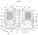
- FIG. It is an enlarged view of the solenoid device which concerns on Example 1.
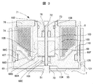
- FIG. It is an enlarged view of the solenoid device which concerns on Example 2.
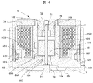
- FIG. It is an enlarged view of the solenoid device which concerns on Example 3.
- the shock absorber of the present invention will be described by taking a shock absorber installed between the vehicle body and the wheels of the vehicle as an example, but the present invention is limited to the configuration shown in the following examples. In the technical concept of the present invention, various modifications and applications are also included in the scope.
- FIG. 1 is a cross-sectional view of a main part of the shock absorber 1 according to the first embodiment of the present invention, which is installed between the vehicle body and the wheels of the vehicle.
- the upward direction (upper side) and the lower direction (lower side) in FIG. 1 are referred to as the upper direction (upper side) and the lower direction (lower side) in the shock absorber 1.
- the first embodiment is a single-cylinder type damping force adjusting type hydraulic shock absorber, it can also be applied to a double-cylinder type damping force adjusting type hydraulic shock absorber provided with a reservoir. Further, when applied to a double-cylinder type damping force adjusting shock absorber composed of an inner cylinder and an outer cylinder, a solenoid device, a damping valve and the like are provided on the outer peripheral side of the outer cylinder.
- the piston 3 is slidably inserted into the cylinder 2.
- the piston 3 divides the inside of the cylinder 2 into two chambers, a cylinder upper chamber 2A and a cylinder lower chamber 2B.
- a working fluid is sealed in the cylinder 2.
- the shaft portion 6 of the piston bolt 5 is inserted into the shaft hole 4 of the piston 3, and the piston 3 is provided in the piston bolt 5.
- the piston bolt 5 is provided with a substantially cylindrical annular base portion 7 extending radially outward, and the annular wall portion 7A located on the upper portion of the annular base portion 7 has a lower end portion of a substantially cylindrical case member 8. It is connected by the screw joint portion 10.
- the piston bolt 5 including the piston 3 is connected to the piston rod 9 via a case member 8.
- the piston bolt 5 is formed with a shaft hole 50 (common passage) extending toward the tip end side (lower side) along the axial direction (vertical direction) and having an upper end opening in the center of the bottom surface of the annular base portion 7.
- the shaft hole 50 includes an axial passage 48 formed in the upper part of the shaft hole 50 and the upper end opens, an axial passage 30 formed in the lower part of the shaft hole 50, and a shaft. It is composed of an axial passage 49 that communicates between the directional passages 30 and 48.
- the diameter (inner diameter) of the shaft hole 50 has the largest diameter of the axial passage 30, and decreases in the order of the axial passage 48 and the axial passage 49.
- the lower end of the piston rod 9 is connected to the upper end of the case member 8 by a screw coupling portion 11.
- a nut 12 is screwed into the lower end of the piston rod 9, and the nut 12 is brought into contact with the upper end of the case member 8 and tightened to prevent the screw coupling portion 11 from loosening.
- a small diameter portion 13 is formed at the lower end of the piston rod 9.
- An O-ring 14 that seals between the case member 8 and the piston rod 9 is mounted on the annular groove formed on the outer peripheral surface of the small diameter portion 13.
- the upper part of the piston rod 9 extends to the outside of the cylinder 2.
- the piston 3 is provided with an extension side passage 15 having one end (upper end) opening toward the cylinder upper chamber 2A side and a contraction side passage 16 having one end (lower end) opening toward the cylinder lower chamber 2B side.
- an extension side damping valve 17 for controlling the flow of the working fluid in the extension side passage 15 is provided.
- a compression side damping valve 18 for controlling the flow of the working fluid in the compression side passage 16 is provided at the upper end of the piston 3.
- the extension side damping valve 17 includes an extension side main valve 20 seated on an annular seat portion 19 formed on the outer peripheral side of the lower end surface of the piston 3, a pilot case 22 fixed to the piston bolt 5 by a nut 21, and an extension side damping valve 17.
- An extension side back pressure chamber 23 formed between the back surface of the side main valve 20 and the pilot case 22 is provided. The pressure in the extension side back pressure chamber 23 acts on the extension side main valve 20 in the valve closing direction.
- a washer 24, a retainer 25, and a disc valve 26 are provided between the nut 21 and the pilot case 22 in this order from the bottom. The inner peripheral edge of the disc valve 26 is sandwiched between the inner peripheral edge of the pilot case 22 and the retainer 25.
- the extension-side main valve 20 is a packing valve in which an annular seal portion 20A made of an elastic body comes into contact with the inner peripheral surface of the pilot case 22 over the entire circumference.
- the extension side back pressure chamber 23 is communicated with the cylinder lower chamber 2B via the passage 27 formed in the pilot case 22 and the disc valve 26.
- the extension side back pressure chamber 23 is always communicated with the cylinder lower chamber 2B via an orifice 26A formed in the disc valve 26.
- the disc valve 26 opens when the pressure in the extension-side back pressure chamber 23 reaches a predetermined pressure to relieve the pressure in the extension-side back pressure chamber 23 to the cylinder lower chamber 2B.
- the extension side back pressure chamber 23 is communicated with a radial passage 29 formed in the piston bolt 5 via a disc type extension side back pressure introduction valve 28.
- the radial passage 29 communicates with the axial passage 30 (common passage) formed in the piston bolt 5.
- the extension side back pressure introduction valve 28 is a check valve that allows only the flow of the working fluid from the radial passage 29 to the extension side back pressure chamber 23.
- the extension-side back pressure introduction valve 28 is seated on an annular seat portion 31 formed on the inner peripheral side of the passage 27 on the upper surface of the pilot case 22.
- the extension side back pressure introduction valve 28 has an inner peripheral edge portion sandwiched between the inner peripheral edge portion of the pilot case 22 and the spacer 32.
- the extension-side back pressure chamber 23 is communicated with the radial passage 29 via the orifice 28A formed in the extension-side back pressure introduction valve 28 by opening the extension-side back pressure introduction valve 28.
- the axial passage 30 communicates with the radial passage 33 (contraction side discharge passage) formed in the piston bolt 5.
- the radial passage 33 communicates with the extension side passage 15 via a contraction side check valve 34 provided in the piston 3.
- the radial passage 33 is always communicated with the extension side passage 15 via the orifice 34A formed in the contraction side check valve 34.
- the contraction side check valve 34 allows only the flow of working fluid from the radial passage 33 to the extension side passage 15.
- the contraction side damping valve 18 is fixed between the contraction side main valve 36 seated on the annular seat portion 35 formed on the outer peripheral side of the upper end surface of the piston 3, the annular base 7 of the piston bolt 5, and the piston 3.
- the piston case 37 is provided with a contraction side back pressure chamber 38 formed between the back surface of the contraction side main valve 36 and the pilot case 37.
- the pressure in the contraction side back pressure chamber 38 acts on the contraction side main valve 36 in the valve closing direction.
- the contraction side main valve 36 is a packing valve in which an annular seal portion 36A made of an elastic body comes into contact with the inner peripheral surface of the pilot case 37 over the entire circumference.
- the contraction side back pressure chamber 38 is communicated with the cylinder upper chamber 2A via the passage 42 and the disc valve 41 formed in the pilot case 37.
- the contraction side back pressure chamber 38 is constantly communicated with the cylinder upper chamber 2A via an orifice 41A formed in the disc valve 41.
- the disc valve 41 opens when the pressure in the contraction side back pressure chamber 38 reaches a predetermined pressure, and relieves the pressure in the contraction side back pressure chamber 38 to the cylinder upper chamber 2A.
- the contraction side back pressure chamber 38 is a radial passage 44 formed in the piston bolt 5 via a circumferential groove 39 formed on the inner peripheral surface of the disc type contraction side back pressure introduction valve 43 and the pilot case 37. Is communicated with.
- the radial passage 44 communicates with the axial passage 48 (common passage) of the piston bolt 5.
- the contraction side back pressure introduction valve 43 is a check valve that allows only the flow of the working fluid from the radial passage 44 to the contraction side back pressure chamber 38.
- the contraction side back pressure introduction valve 43 is seated on the annular seat portion 45 formed on the inner peripheral side of the passage 42 on the lower surface of the pilot case 37.
- the inner peripheral edge of the contraction side back pressure introduction valve 43 is sandwiched between the inner peripheral edge of the pilot case 37 and the spacer 40.
- the contraction side back pressure chamber 38 is communicated with the radial passage 44 via the orifice 43A formed in the contraction side back pressure introduction valve 43 by opening the contraction side back pressure introduction valve 43.
- the axial passage 48 communicates with the radial passage 46 (extension side discharge passage) formed in the piston bolt 5.
- the radial passage 46 communicates with the contraction side passage 16 via the extension side check valve 47 provided on the piston 3.
- the radial passage 46 is always communicated with the contraction side passage 16 via the orifice 47A formed in the extension side check valve 47.
- the extension side check valve 47 allows only the flow of working fluid from the radial passage 46 to the contraction side passage 16.
- the flow of the working fluid in the shaft hole 50 (common passage) of the piston bolt 5 is controlled by the pilot valve.
- the pilot valve has a valve spool 51 (valve body) slidably fitted in the shaft hole 50.
- the valve spool 51 is composed of a solid shaft and constitutes a pilot valve together with the piston bolt 5.
- the valve spool 51 is located in the axial passage 48 with a base portion 52 slidably fitted to the upper portion of the axial passage 48, in other words, a portion above the radial passage 44, via a tapered portion 53.
- a valve portion 54 continuous with the base portion 52, a tip portion 55 (fitting portion) located in the axial passage 30 in the closed state of the pilot valve, and a connecting portion 56 connecting the tip portion 55 and the valve portion 54. And have.
- the diameter (outer diameter) of the valve spool 51 is largest in the base portion 52, and decreases in the order of the valve portion 54, the tip portion 55, and the connecting portion 56. Further, the outer diameter of the valve portion 54 is larger than the inner diameter of the axial passage 49.
- the valve spool 51 is urged upward with respect to the piston bolt 5 by the valve spring 59 interposed between the spring receiving portion 57 of the tip portion 55 and the spring receiving portion 58 of the piston bolt 5.
- the end face of the base 52 is abutted (pressed) against the rod 72 of the solenoid device 71, which will be described later.
- the tip 55 is stroked in the valve opening direction (upward in FIG. 3) when the control current to the solenoid device 71 used as an actuator for controlling the movement of the valve spool 51 is 0A (when failing). It is fitted into the axial passage 49.
- a pair of orifices communicating between the axial passages 30 and 48 are formed between the tip portion 55 and the axial passage 49.
- An annular seat portion 63 on which the valve portion 54 of the valve spool 51 is seated is formed at the opening peripheral edge of the upper end (axial passage 48 side) of the axial passage 49.
- a tapered seating surface 54A is formed on the outer peripheral edge of the lower end (connecting portion 56 side) of the valve portion 54.
- the pressure receiving surface inside the seat portion 63 receives the pressure on the axial passage 30 side, and the tapered portion 53 receives the pressure on the axial passage 48 side on the annular pressure receiving surface formed between the outer diameter of the base portion 52 and the seat portion 63. receive.
- the solenoid device 71 of the present embodiment includes a case member 8, a rod 72, a fixed iron core 68 (anchor), an upper core 76, a guide 103, a housing 102, a bobbin 109, and a bobbin 109. , Coil 74 and the like, and a movable iron core 69 (plunger) movable in the axial direction is coupled to the outer peripheral surface of the rod 72.
- the storage space formed by the upper core 76, the fixed iron core 68, etc. has the same height on the outer peripheral side and the inner peripheral side on the upper side, and is inside the outer peripheral side on the lower side. It has a substantially trapezoidal cross-sectional shape with the peripheral side at the bottom.
- the lower surface of the upper core 76 that defines the upper shape of the storage space is flat, and the upper surface of the fixed iron core 68 that defines the lower shape of the storage space.
- an inclined surface 68D having a high outer peripheral side and a low inner peripheral side is provided over the entire circumference.
- the upper portion of the bobbin 109 is flat so that the bobbin 109 can be stored in such a storage space, and an inclined surface along the inclined surface 68D of the fixed iron core 68 is provided at the lower portion.
- the fixed iron core 68 is arranged so as to be in contact with the upper surface of the annular base portion 7, and has a substantially annular inner convex portion 68A on the inner peripheral side of the upper surface as shown in FIG. It is a substantially cylindrical iron core having a substantially annular outer convex portion 68C on the outer peripheral side and a through hole 68E communicating vertically in the center. Further, on the outer peripheral side of the inner convex portion 68A, a protruding portion 68B (also referred to as an axial height changing portion) projecting upward is provided.
- the protruding portion 68B is formed so that the inner peripheral side is high and the outer peripheral side is low, and the protruding portion 68B serves as a path of the magnetic path M toward the movable iron core 69. Further, a groove 68F for arranging the seal 107 in a circumferential shape is formed on the outer peripheral surface of the outer convex portion 68C.
- a non-magnetic non-magnetic cylindrical member 105 that fits with the outer circumference of the protruding portion 68B is arranged.
- the hole diameter inside the cylinder is large on the upper end side and the lower end side, and is smaller on the intermediate portion.
- An inclined portion is formed in the lower portion of the intermediate portion having a small hole diameter so that the diameter gradually increases so as to face the protruding portion 68B of the fixed iron core 68.
- a bush 106 is arranged in the through hole 68E of the fixed iron core 68, and the rod is supported so as to be movable in the vertical direction (axial direction) via the bush 106.
- the movable iron core 69 is formed in a substantially cylindrical shape by an iron-based magnetic material, and its outer diameter is designed to be slightly smaller than the inner diameter of the protruding portion 68B of the fixed iron core 68, and the inside of the protruding portion 68B is vertically oriented. Arranged so that it can be moved.
- the rod 72 is formed in a cylindrical shape and has an in-rod passage 73 that penetrates (extends) the rod 72 in the axial direction (vertical direction).
- the bobbin 109 is arranged outside the guide 103 and the non-magnetic cylindrical member 105, and has a cylindrical shape with upper and lower collars, and a coil 74 is wound between the upper and lower collars. Further, a resin 110 is formed on the outside of the coil 74. A magnetic upper core 76 is installed above the collar on the upper side of the bobbin 109.
- the lead wire connected to the coil 74 is taken out from the upper part of the bobbin 109, passes through the inside of the piston rod 9 via the connection portion, and can be energized from the outside.
- a cylindrical housing 102 having a bottomed cylindrical hole is arranged on the upper side of the rod 72 and the movable iron core 69 through a space for them to stroke. Further, as shown in FIG. 2, the outer diameter side of the housing 102 is fitted to the upper side of the guide 103 via the seal 108. Further, the inner peripheral side of the cylindrical hole of the housing 102 supports the rod 72 so as to be movable in the vertical direction (axial direction) via the bush 78.
- a magnetic flux flow (magnetic path M) is generated as shown by a broken line in the figure due to a magnetic field generated when the coil 74 is energized, and is attracted to the fixed iron core 68 in the axial direction. Thrust is generated.
- the space having a variable volume formed between the fixed iron core 68 and the movable iron core 69 is referred to as a suction space.
- the magnetic path M passing through the lower part of the guide 103 passes through the movable iron core 69 to the inner surface of the protruding portion 68B of the fixed iron core 68 and the upper surface of the inner convex portion 68A. Need to be reached. In other words, it is necessary to suppress the generation of a magnetic path from the guide 103 to the fixed iron core 68 without passing through the movable iron core 69. For that purpose, it is effective to provide a non-magnetic portion between the guide 103 and the fixed iron core 68.
- the non-magnetic cylindrical member 105 sandwiched between the lower surface of the guide 103 and the protruding portion 68B of the fixed iron core 68.
- a non-magnetic part was formed. Since what is needed is a non-magnetic part between the guide 103 and the fixed iron core 68, for example, if the guide 103 can be fixed to the upper core 76, the non-magnetic cylindrical member 105 as a support member of the guide 103 is omitted. , The air between the guide 103 and the fixed iron core 68 may function as a non-magnetic portion.
- the non-magnetic cylindrical member 105 and the bobbin 109 provided on the outer peripheral side of the protruding portion 68B serve as the non-magnetic portion.
- the seal 107 it is necessary to arrange the seal 107 on the outer peripheral surface of the fixed iron core 68 so that the fluid of the cylinder upper chamber 2A does not flow into the coil 74 side.
- the fixed iron core 68 of the present embodiment by providing the inclined surface 68D described above, a portion in which the axial length of the fixed iron core 68 is long on the outer peripheral side and short on the inner peripheral side is formed.
- the flow of magnetic flux becomes smooth, and there is an effect of efficiently generating thrust in the movable iron core 69.
- the spool back pressure chamber 70 (chamber) together with the inside of the circumferential groove 104 provided on the lower surface of the fixed iron core 68 and the inside of the circumferential groove 95 formed on the upper surface of the annular base 7 of the piston bolt 5. ) Is formed.
- the upper end of the valve spool 51 and the lower end of the rod 72 are brought into contact with each other in the spool back pressure chamber 70 at the upper end (one side end) of the pilot valve.
- the spool back pressure chamber 70 is communicated with the cylinder upper chamber 2A via the upper chamber side communication passage when the pilot valve is closed.
- the upper chamber side continuous passage is a passage (not shown) between the circumferential groove portion 104 and the annular space 120 formed between the inside of the annular wall portion 7A and the outer peripheral side of the fixed iron core 68, the annular space 120 and the cylinder upper chamber 2A. It is composed of an orifice passage 121 provided in the annular wall portion 7A.
- a spool back pressure relief valve 81 (check valve), a retainer 82, a plate 83, a disc 84, a retainer 85, and a disc valve 41 are provided between the annular base 7 of the piston bolt 5 and the pilot case 37 in this order from the upper side. Be done. The inner peripheral edge of the disc valve 41 is sandwiched between the inner peripheral edge of the pilot case 37 and the retainer 85.
- the inner peripheral edge portion is sandwiched between the retainer 82 and the inner peripheral edge portion of the annular base portion 7 of the piston bolt 5, and the outer peripheral edge portion is an annular shape formed on the lower surface of the annular base portion 7 of the piston bolt 5. It is seated on the seat portion 88. Further, the check valve lower chamber 89 (annular space) is used as a space for opening the spool back pressure relief valve 81.
- the spool back pressure relief valve 81 is a check valve that allows only the flow of working fluid from the spool back pressure chamber 70 to the check valve lower chamber 89.
- the spool back pressure chamber 70 is communicated with the cylinder lower chamber 2B via a lower chamber side communication passage (communication passage).
- the lower chamber side continuous passage extends the circumferential groove 94 formed inside the seat portion 88 on the lower surface of the annular base 7 of the piston bolt 5 and the annular base 7 of the piston bolt 5 in the vertical direction to form the circumferential groove 95.
- 94 has a passage 96 for communicating with each other.
- the circumferential groove 104, the circumferential groove 95, the passage 96, and the circumferential groove 94 form a flow path in which the flow of the working fluid is generated by the movement of the piston rod 9.
- the spool back pressure relief valve 81 provided in the flow path serves as a valve for opening and closing the flow path.
- the lower chamber side passage is further formed on the upper surface of the plate 83 and extends radially outward from the inner peripheral surface of the plate 83, and is formed on the lower surface of the plate 83 in the radial direction from the inner peripheral surface of the plate 83.
- a groove 92 extending outward, a passage 91 extending vertically from the plate 83 to communicate between the grooves 90 and 92, and a diameter formed on the outer peripheral surface of the shaft portion 6 of the piston bolt 5 and formed on the piston bolt 5. It has a groove 93 that communicates the directional passage 44 and the groove 92.
- the check valve lower chamber 89 is communicated with the axial passage 48 via the groove 90, the passage 91, the groove 92, the groove 93, and the radial passage 44.
- the groove 93 is formed by processing the width across flats of the shaft portion 6 of the piston bolt 5.
- contraction stroke the working fluid of the cylinder lower chamber 2B is before the contraction side main valve 36 is opened, the contraction side passage 16, and the extension side check valve 47.
- valve spool 51 (valve body) moves and the valve portion 54 is separated from the seat portion 63. That is, when the pilot valve is opened, the working fluid of the cylinder lower chamber 2B is the contraction side passage 16, the extension side check valve 47 orifice 47A, the radial passage 46, the axial passage 48, the axial passage 49, and the like. It flows to the cylinder upper chamber 2A through the axial passage 30, the radial passage 33, the contraction side check valve 34, and the extension side passage 15.
- the valve opening pressure of the pilot valve can be adjusted by controlling the energizing current of the solenoid device 71 to the coil 74.
- the pressure of the working fluid introduced from the contraction side back pressure introduction valve 43 into the contraction side back pressure chamber 38 is also adjusted, so that the valve opening pressure of the contraction side main valve 36 can be controlled.
- the contraction side main valve 36 is opened, the working fluid also flows from the cylinder lower chamber 2B to the cylinder upper chamber 2A in the flow path passing through the contraction side main valve 36.
- extension stroke the working fluid of the cylinder upper chamber 2A is before the extension side main valve 20 is opened, the extension side passage 15, and the contraction side check valve 34.
- valve spool 51 (valve body) moves and the valve portion 54 is separated from the seat portion 63. That is, when the pilot valve is opened, the working fluid of the cylinder upper chamber 2A is the extension side passage 15, the orifice 34A of the contraction side check valve 34, the radial passage 33, the axial passage 30, the axial passage 49, and the like. It flows to the cylinder lower chamber 2B through the axial passage 48, the radial passage 46, the extension side check valve 47, and the contraction side passage 16.
- the valve opening pressure of the pilot valve can be adjusted by controlling the energizing current of the solenoid device 71 to the coil 74.
- the pressure of the working fluid introduced from the extension side back pressure introduction valve 28 into the extension side back pressure chamber 23 is also adjusted, so that the valve opening pressure of the extension side main valve 20 can be controlled.
- the extension side main valve 20 is opened, the working fluid of the cylinder upper chamber 2A also flows to the cylinder lower chamber 2B in the flow path passing through the extension side main valve 20.
- the working fluid of the cylinder upper chamber 2A flows into the spool back pressure chamber 70 (chamber) through the upper chamber side continuous passage. That is, the working fluid of the cylinder upper chamber 2A flows into the spool back pressure chamber 70 through the orifice passage 121.
- the working fluid that has flowed into the spool back pressure chamber 70 flows to the cylinder lower chamber 2B through the lower chamber side communication passage (communication passage).
- the working fluid flowing into the spool back pressure chamber 70 is the passage 96, the circumferential groove 94, the spool back pressure relief valve 81 (check valve), the check valve lower chamber 89, the groove 90, the passage 91, the groove 92, and the groove. It flows to the cylinder lower chamber 2B through 93, the radial passage 44, the axial passage 48, the radial passage 46, the orifice 47A of the extension side check valve 47, and the contraction side passage 16.
- the valve spool 51 moves upward, the working fluid generated by the movement flows to the cylinder lower chamber 2B through the lower chamber side communication passage.
- the spool back pressure relief valve 81 Since the spool back pressure relief valve 81 is kept closed during the shrinking process, the spool back pressure chamber 70 communicates with the low-pressure cylinder upper chamber 2A through the upper chamber side communication passage, so that the valve spool When is moved upward, the working fluid generated by the movement is discharged to the cylinder lower chamber 2B through the upper chamber side communication passage.
- the sealing portion is formed by making the axial length of the fixed iron core 68 longer on the outer peripheral side and shorter on the inner peripheral side by the inclined surface 68D on the upper surface of the fixed iron core 68. It is possible to keep the axial length of the fixed iron core 68 not long while forming the necessary magnetic path, and the solenoid device 71 can be miniaturized.
- Example 2 of the present invention will be described with reference to FIG.
- FIG. 3 is a partially enlarged view of the shock absorber according to the second embodiment of the present invention.
- the differences from the first embodiment will be mainly described.
- the parts common to those in Example 1 are represented by the same names and the same reference numerals.
- the shape of the bobbin 109 and the method of winding the coil 74 are different from those of the first embodiment.
- the bobbin 109 is cylindrical and has a collar at the upper part, but does not have a collar at the lower part.
- the coil 74 is wound from the upper end of the outer side of the cylinder of the bobbin 109 and is formed by repeatedly folding back at the lower part and the upper part, but the lower folding position gradually rises from the inside to the outside and the fixed iron core 68. It is formed along the inclined surface 68D of.
- Example 3 of the present invention will be described with reference to FIG.
- FIG. 4 is a partially enlarged view of the shock absorber according to the third embodiment of the present invention.
- the differences from the first embodiment will be mainly described.
- the parts common to those in Example 1 are represented by the same names and the same reference numerals.
- FIG. 4 which shows Example 3, the shape of the bobbin 109, the method of winding the coil 74, and the shape of the fixed iron core 68 are different from those of Example 1.
- the fixed iron core 68 has a shape having an inner convex portion 68A on the inner surface and an outer convex portion 68C on the outer surface outside when viewed in an axial cross section, and has a cylindrical shape having a through hole 68E connecting the upper and lower surfaces at the center.
- the outer convex portion on the upper surface is different from the first embodiment in that the axial length changing portion 68G is formed in a stepped manner on the inner peripheral side as well.
- the bobbin 109 has a cylindrical shape with upper and lower collars, but the length of the collar is shorter on the lower side than on the upper side.
- the coil 74 is wound from the upper end inside the upper part of the bobbin 109, and is formed by repeatedly folding back at the lower part and the upper part. However, when the lower folding position is initially from the inside to the outside, the folding position does not change. With respect to the portion protruding outside the length of the lower collar of the bobbin 109, the folded position is formed so as to gradually move upward.
- shock absorber 2 ... cylinder, 2A ... cylinder upper chamber, 2B ... cylinder lower chamber, 3 ... piston, 5 ... piston bolt, 8 ... case member, 9 ... piston rod, 68 ... fixed iron core, 69 ... movable iron core, 70 ... spool back pressure chamber, 71 ... solenoid device (electric actuator), 74 ... coil, 81 ... spool back pressure relief valve (check valve), 105 ... non-magnetic cylinder member, 107 ... seal, 109 ... bobbin
Landscapes
- Physics & Mathematics (AREA)
- Electromagnetism (AREA)
- Engineering & Computer Science (AREA)
- Power Engineering (AREA)
- General Engineering & Computer Science (AREA)
- Mechanical Engineering (AREA)
- Electromagnets (AREA)
- Magnetically Actuated Valves (AREA)
- Fluid-Damping Devices (AREA)
Abstract
本発明の課題は、ソレノイド装置の必要推力とシール性を確保しつつ軸長を短縮することである。そのため、コイル74を巻いたボビン109と、該ボビンを収納する収納空間の下端面を形成する固定鉄心68と、該固定鉄心の上端面と対向配置され、軸方向に移動する可動鉄心69と、前記固定鉄心の外周面に設けたシール部107と、を備えたソレノイド装置71であって、前記固定鉄心の上端面の内周側には、内周側が高く外周側が低い略環状の突出部68Bが前記可動鉄心の外周面と対向するように形成されており、前記シール部は、前記突出部と重なる軸方向高さに設けられているソレノイド装置とした。
Description
本発明は、電磁力を発生するソレノイド装置、および、それを内蔵した緩衝器に関する。
車両の車体と車輪の間に設置する緩衝器として、減衰力調整弁を切換える電動アクチュエータ(ソレノイド装置)をピストンロッドに内蔵した減衰力調整式油圧緩衝器が知られている。
このような技術として、例えば、特許文献1の請求項1では、「コイルが巻装されたボビンの内部に固定鉄心および可動鉄心を挿入したソレノイド装置において、前記ボビンの内周に、前記固定鉄心に対向させて、円筒状の磁性スリーブを嵌合し、該磁性スリーブ内に前記固定鉄心を嵌合したことを特徴とするソレノイド装置」が提案されている。
特許文献1のソレノイド装置では、同文献の図2等に示されるように、固定鉄心に相当するピストンボルト20の外周面にシールを配置することで流体がシリンダ上室側からコイル側に流入するのを防止する構成であるため、シール性を確保しつつソレノイドの軸長を短縮すると必要な磁路面積の確保が難しく、推力が小さくなってしまうため、小型化が難しいという課題があった。
そこで、本発明では、必要なシール性と推力を確保しつつ、軸長の拡大を抑制できるソレノイド装置を提供することを目的とする。
上記目的を達成するために本発明のソレノイド装置は、コイルを巻いたボビンと、該ボビンを収納する収納空間の下端面を形成する固定鉄心と、該固定鉄心の上端面と対向配置され、軸方向に移動する可動鉄心と、前記固定鉄心の外周面に設けたシール部と、を備えたものであって、前記固定鉄心の上端面の内周側には、内周側が高く外周側が低い略環状の突出部が前記可動鉄心の外周面と対向するように形成されており、前記シール部は、前記突出部と重なる軸方向高さに設けられているものとした。
本発明のソレノイド装置によれば、必要なシール性と推力を確保しつつ、軸長の拡大を抑制することができる。
以下、本発明に係るソレノイド装置、および、それを内蔵した減衰力調整式油圧緩衝器
(以下、単に「緩衝器」と称する。)の実施例を図面に基づいて説明する。なお、以下の実施例では、車両の車体と車輪の間に設置した緩衝器を例に、本発明の緩衝器を説明するが、本発明は、以下の実施例に示した構成に限定されることなく、本発明の技術的な概念の中で種々の変形例や応用例もその範囲に含むものである。
(以下、単に「緩衝器」と称する。)の実施例を図面に基づいて説明する。なお、以下の実施例では、車両の車体と車輪の間に設置した緩衝器を例に、本発明の緩衝器を説明するが、本発明は、以下の実施例に示した構成に限定されることなく、本発明の技術的な概念の中で種々の変形例や応用例もその範囲に含むものである。
図1は、車両の車体と車輪の間に設置した、本発明の実施例1に係る緩衝器1の主要部の断面図である。以下の説明において、図1における上方向(上側)および下方向(下側)を、緩衝器1における上方向(上側)および下方向(下側)とする。なお、実施例1は、単筒型の減衰力調整式油圧緩衝器であるが、リザーバを備える複筒型の減衰力調整式油圧緩衝器にも適用できる。さらに、内筒、外筒とからなる複筒型の減衰力調整式緩衝器に適用した場合には、外筒の外周側に、ソレノイド装置、減衰弁などが設けられる。
図1に示されるように、シリンダ2内には、ピストン3が摺動可能に挿入される。ピストン3は、シリンダ2内をシリンダ上室2Aとシリンダ下室2Bとの2室に区画する。シリンダ2内には作動流体が封入されている。ピストン3の軸孔4には、ピストンボルト5の軸部6が挿通され、ピストンボルト5にピストン3が備えられる。ピストンボルト5には径方向外側に延びた略円筒形の環状基部7が備えられ、この環状基部7の上側部分に位置する環状壁部7Aには、略円筒形のケース部材8の下端部がねじ結合部10で接続される。ピストン3を備えるピストンボルト5は、ケース部材8を介してピストンロッド9と連結されている。ピストンボルト5には、軸方向(上下方向)に沿って先端側(下側)へ延びて上端が環状基部7の底面中央に開口する軸孔50(共通通路)が形成される。
また、図2に示されるように、軸孔50は、軸孔50の上部に形成されて上端が開口する軸方向通路48と、軸孔50の下部に形成される軸方向通路30と、軸方向通路30、48間を連通させる軸方向通路49とにより構成される。軸孔50の径(内径)は、軸方向通路30の径が最も大きく、軸方向通路48、軸方向通路49の順に小さくなる。
ケース部材8の上端部には、ピストンロッド9の下端部がねじ結合部11で接続される。ピストンロッド9の下端部には、ナット12が螺合され、ナット12をケース部材8の上端に当接させて締め付けることにより、ねじ結合部11の緩みが抑止される。ピストンロッド9の下端には、小径部13が形成される。小径部13の外周面に形成された環状溝には、ケース部材8とピストンロッド9との間をシールするOリング14が装着される。
ピストンロッド9の上部はシリンダ2の外部へ延びている。ピストン3には、一端(上端)がシリンダ上室2A側に開口する伸び側通路15と、一端(下端)がシリンダ下室2B側に開口する縮み側通路16とが設けられる。ピストン3の下端には、伸び側通路15の作動流体の流れを制御する伸び側減衰弁17が設けられる。ピストン3の上端には、縮み側通路16の作動流体の流れを制御する縮み側減衰弁18が設けられる。
ピストンロッド9の上部はシリンダ2の外部へ延びている。ピストン3には、一端(上端)がシリンダ上室2A側に開口する伸び側通路15と、一端(下端)がシリンダ下室2B側に開口する縮み側通路16とが設けられる。ピストン3の下端には、伸び側通路15の作動流体の流れを制御する伸び側減衰弁17が設けられる。ピストン3の上端には、縮み側通路16の作動流体の流れを制御する縮み側減衰弁18が設けられる。
伸び側減衰弁17は、ピストン3の下端面の外周側に形成された環状のシート部19に着座する伸び側メインバルブ20と、ナット21によってピストンボルト5に固定されるパイロットケース22と、伸び側メインバルブ20の背面とパイロットケース22との間に形成される伸び側背圧室23とを備える。伸び側背圧室23内の圧力は、伸び側メインバルブ20に対して閉弁方向へ作用する。ナット21とパイロットケース22との間には、下側から順に、ワッシャ24、リテーナ25、およびディスクバルブ26が設けられる。ディスクバルブ26の内周縁部は、パイロットケース22の内周縁部とリテーナ25との間で挟持される。なお、伸び側メインバルブ20は、弾性体からなる環状のシール部20Aがパイロットケース22の内周面に全周にわたって接触するパッキンバルブである。
伸び側背圧室23は、パイロットケース22に形成された通路27およびディスクバルブ26を介してシリンダ下室2Bに連通される。伸び側背圧室23は、ディスクバルブ26に形成されたオリフィス26Aを介してシリンダ下室2Bに常時連通される。ディスクバルブ26は、伸び側背圧室23の圧力が所定圧力に達したときに開弁して伸び側背圧室23内の圧力をシリンダ下室2Bへリリーフする。また、伸び側背圧室23は、ディスク型の伸び側背圧導入弁28を介して、ピストンボルト5に形成された径方向通路29に連通される。径方向通路29は、ピストンボルト5に形成された軸方向通路30(共通通路)に連通される。
伸び側背圧導入弁28は、径方向通路29から伸び側背圧室23への作動流体の流れのみを許容する逆止弁である。伸び側背圧導入弁28は、パイロットケース22の上面の、通路27の内周側に形成された環状のシート部31に着座される。伸び側背圧導入弁28は、内周縁部がパイロットケース22の内周縁部とスペーサ32との間で挟持される。伸び側背圧室23は、伸び側背圧導入弁28が開弁することで、伸び側背圧導入弁28に形成されたオリフィス28Aを介して径方向通路29に連通される。
軸方向通路30は、ピストンボルト5に形成された径方向通路33(縮み側排出通路)に連通される。径方向通路33は、ピストン3に設けられた縮み側逆止弁34を介して伸び側通路15に連通される。径方向通路33は、縮み側逆止弁34に形成されたオリフィス34Aを介して伸び側通路15に常時連通される。縮み側逆止弁34は、径方向通路33から伸び側通路15への作動流体の流れのみを許容する。
縮み側減衰弁18は、ピストン3の上端面の外周側に形成された環状のシート部35に着座する縮み側メインバルブ36と、ピストンボルト5の環状基部7とピストン3との間で固定されるパイロットケース37と、縮み側メインバルブ36の背面とパイロットケース37との間に形成される縮み側背圧室38とを備える。縮み側背圧室38内の圧力は、縮み側メインバルブ36に対して閉弁方向へ作用する。なお、縮み側メインバルブ36は、弾性体からなる環状のシール部36Aがパイロットケース37の内周面に全周にわたって接触するパッキンバルブである。
縮み側背圧室38は、パイロットケース37に形成された通路42およびディスクバルブ41を介してシリンダ上室2Aに連通される。縮み側背圧室38は、ディスクバルブ41に形成されたオリフィス41Aを介してシリンダ上室2Aに常時連通される。ディスクバルブ41は、縮み側背圧室38の圧力が所定圧力に達したときに開弁し、縮み側背圧室38内の圧力をシリンダ上室2Aへリリーフする。また、縮み側背圧室38は、ディスク型の縮み側背圧導入弁43およびパイロットケース37の内周面に形成された円周溝39を介してピストンボルト5に形成された径方向通路44に連通される。径方向通路44は、ピストンボルト5の軸方向通路48(共通通路)に連通される。
縮み側背圧導入弁43は、径方向通路44から縮み側背圧室38への作動流体の流れのみを許容する逆止弁である。縮み側背圧導入弁43は、パイロットケース37の下面の、通路42の内周側に形成された環状のシート部45に着座される。縮み側背圧導入弁43の内周縁部は、パイロットケース37の内周縁部とスペーサ40との間で挟持される。縮み側背圧室38は、縮み側背圧導入弁43が開弁することで、縮み側背圧導入弁43に形成されたオリフィス43Aを介して径方向通路44に連通される。
軸方向通路48は、ピストンボルト5に形成された径方向通路46(伸び側排出通路)に連通される。径方向通路46は、ピストン3に設けられた伸び側逆止弁47を介して縮み側通路16に連通される。径方向通路46は、伸び側逆止弁47に形成されたオリフィス47Aを介して縮み側通路16に常時連通される。伸び側逆止弁47は、径方向通路46から縮み側通路16への作動流体の流れのみを許容する。
ピストンボルト5の軸孔50(共通通路)内の作動流体の流れは、パイロット弁によって制御される。パイロット弁は、軸孔50に摺動可能に嵌装されたバルブスプール51(弁体)を有する。バルブスプール51は、中実軸からなり、ピストンボルト5とともにパイロット弁を構成する。バルブスプール51は、軸方向通路48の上部、換言すると、径方向通路44よりも上側部分に摺動可能に嵌合される基部52と、軸方向通路48内に位置してテーパ部53を介して基部52に連続する弁部54と、パイロット弁の閉弁状態で軸方向通路30内に位置する先端部55(嵌合部)と、先端部55と弁部54とを接続する接続部56とを有する。なお、バルブスプール51の径(外径)は、基部52が最も大きく、弁部54、先端部55、接続部56の順に小さくなる。また、弁部54の外径は、軸方向通路49の内径よりも大きい。
バルブスプール51は、先端部55のばね受部57とピストンボルト5のばね受部58との間に介装された弁ばね59によってピストンボルト5に対して上方向へ付勢されることにより、基部52の端面が、後述するソレノイド装置71のロッド72に当接される(押し付けられる)。先端部55は、バルブスプール51の移動を制御するアクチュエータとして用いられるソレノイド装置71への制御電流が0Aのとき(フェイル時)、バルブスプール51が開弁方向(図3における上方向)へストロークされて軸方向通路49に嵌合される。これにより、先端部55と軸方向通路49との間には、軸方向通路30、48間を連通する一対のオリフィスが形成される。
軸方向通路49の上端(軸方向通路48側)の開口周縁部には、バルブスプール51の弁部54が着座する環状のシート部63が形成される。弁部54の下端(接続部56側)の外周縁部には、テーパ状に形成された着座面54Aが形成される。バルブスプール51の着座面54Aが、ピストンボルト5の軸孔50に形成されたシート部63に着座された状態、すなわち、パイロット弁の閉弁状態では、バルブスプール51は、先端部55が略円形でシート部63の内側の受圧面で軸方向通路30側の圧力を受け、テーパ部53は基部52の外径とシート部63の間にできる環状の受圧面で軸方向通路48側の圧力を受ける。
ここで、本実施例のソレノイド装置71は、図2の拡大図に示すように、ケース部材8、ロッド72、固定鉄心68(アンカ)、上部コア76、ガイド103、ハウジング102、ボビン109、および、コイル74等から構成されており、ロッド72の外周面には、軸方向に移動可能な可動鉄心69(プランジャ)が結合されている。
ボビン109の上下鍔間にはコイル74が巻かれている。このボビン109は、ソレノイド装置71の外周側に配置された略円筒形のケース部材8と、上部に配置された平環状の上部コア76と、ロッド72を囲むように配置された略円筒形のガイド103と、下部に配置された固定鉄心68等で囲まれた収納空間に収納されている。そして、コイル74に通電したときに、ケース部材8、上部コア76、ガイド103、可動鉄心69、固定鉄心68、を順次通る、図2中では破線で示す磁路Mが形成され、可動鉄心69とロッド72を軸方向に一体移動させる推力が発生する。
なお、上部コア76や固定鉄心68等によって形成される収納空間は、図2の断面図に示すように、上側では外周側と内周側の高さが等しく、下側では外周側よりも内周側が下方にある、略台形状の断面形状をしている。このような断面形状の収納空間を形成するため、収納空間の上側形状を規定する上部コア76の下面は平坦になっており、また、収納空間の下側形状を規定する固定鉄心68の上面の外周側には、全周に亘り、外周側が高く内周側が低い傾斜面68Dが設けられている。そして、このような収納空間に収納できるよう、ボビン109の上部は平坦になっており、下部には固定鉄心68の傾斜面68Dに沿った傾斜面が設けられている。
更に詳述すると、固定鉄心68は、環状基部7の上面に接触するように配置されるもので、図2に示すように、上面内周側に略環状の内側凸部68Aを有し、上面外周側に略環状の外側凸部68Cを有し、中心には上下連通する貫通穴68Eを有する略円筒形状の鉄心である。さらに、内側凸部68Aの外周側には、上側に突出する突出部68B(軸方向高さ変更部とも称する)を有する。この突出部68Bは内周側が高く外周側が低くなるように形成されており、この突出部68Bが可動鉄心69に向かう磁路Mの経路となる。また、外側凸部68Cの外周面には円周状にシール107を配置するための溝68Fが形成される。
固定鉄心68の上方には、突出部68Bの外周と勘合する非磁性体の非磁性円筒部材105が配置される。この非磁性円筒部材105は、円筒内側の穴径が上端側と下端側で大きく、中間部で小さくなっている。穴径の小さい中間部の下部は、固定鉄心68の突出部68Bと対向するように径が徐々に広がるように傾斜部が形成されている。
また、非磁性円筒部材105の上方には、非磁性円筒部材105の上端内周と勘合する略円筒形のガイド103が配置される。このガイド103は、上端部から中間部にかけて外径の大きい大外径部を有し、非磁性円筒部材105の上端内周と勘合する下端部には外径が小さい小外径部を有するように形成される。この結果、ガイド103の下面は非磁性円筒部材105の中間部の上面と接触するように配置される。
固定鉄心68の貫通穴68Eにはブッシュ106が配置され、このブッシュ106を介してロッドが上下方向(軸方向)へ移動可能に支持される。
可動鉄心69は、鉄系の磁性体により略円筒形に形成され、その外径は、固定鉄心68の突出部68Bの内径よりもやや小さく設計されており、突出部68Bの内側を上下方向に移動できるように配置される。
ロッド72は、円筒形に形成され、ロッド72を軸方向(上下方向)に貫通する(延びる)ロッド内通路73を有する。
ボビン109は、ガイド103および非磁性円筒部材105の外側に配置され、円筒形状で上下に鍔を持った形状であり、上下の鍔の間をコイル74が巻かれている。また、コイル74の外側には樹脂110が成形される。ボビン109の上側の鍔部の上側には磁性体の上部コア76が設置される。
コイル74に接続されたリード線は、ボビン109の上部から取り出され、結線部を介してピストンロッド9の内部を通り、外部から通電できるようになっている。
ロッド72および可動鉄心69の上側には、図1に示すように、それらがストロークするための空間を介して有底の円筒穴を有する円筒状のハウジング102が配置される。また、ハウジング102は、図2に示すように、外径側がシール108を介して、ガイド103の上部側に勘合される。さらに、ハウジング102の円筒穴の内周側は、ブッシュ78を介してロッド72を上下方向(軸方向)へ移動可能に支持する。
可動鉄心69には、コイル74に通電されると発生する磁界により磁束の流れ(磁路M)が図中の破線のように発生し、固定鉄心68との間で軸方向に吸引する方向の推力が発生する。なお、固定鉄心68と可動鉄心69の間に形成される、容積可変の空間を吸引空間と称する。
ここで、可動鉄心69に効率よく推力を発生させるには、ガイド103の下部を通る磁路Mが、可動鉄心69を経由して固定鉄心68の突出部68Bの内面や内側凸部68Aの上面に至る必要がある。換言すれば、可動鉄心69を経由せずにガイド103から固定鉄心68に至る磁路の発生を抑制する必要がある。そのためには、ガイド103と固定鉄心68の間に非磁性部を設けることが有効であり、本実施例では、ガイド103の下面と固定鉄心68の突出部68Bで挟んだ非磁性円筒部材105により非磁性部を形成した。なお、必要なのはあくまでガイド103と固定鉄心68の間の非磁性部であるから、例えば上部コア76にガイド103を固定できるのであれば、ガイド103の支持部材としての非磁性円筒部材105を省略し、ガイド103と固定鉄心68の間の空気に非磁性部の機能を担わせても良い。
また、可動鉄心69に効率よく推力を発生させるには、固定鉄心68の内周側の突出部68Bにも、可動鉄心69を通った磁束を集中させる必要があるため、突出部68Bの外周側にも非磁性部が必要である。本実施例では、突出部68Bの外周側に設けた非磁性円筒部材105とボビン109が非磁性部の役割を果たす。一方で、固定鉄心68の外周面にはシリンダ上室2Aの流体がコイル74側に入流しないようにシール107を配置する必要がある。そこで、本実施例の固定鉄心68では、上述した傾斜面68Dを設けることによって、固定鉄心68の軸方向長さが外周側で長く、内周側で短くなる部分を形成した。この傾斜面68Dで軸方向長さを傾斜で変化させることで、磁束の流れがスムーズになり、可動鉄心69に効率よく推力を発生させる効果がある。
貫通穴68Eの内側には、固定鉄心68の下面に設けた円周溝104の内側、ピストンボルト5の環状基部7の上面に形成された円周溝95の内側と共にスプール背圧室70(室)が形成される。バルブスプール51の上端とロッド72の下端とは、パイロット弁の上端(一側端)のスプール背圧室70内で当接される。スプール背圧室70は、パイロット弁の閉弁時に、上室側連通路を介してシリンダ上室2Aに連通される。
上室側連通路は、円周溝部104と、環状壁部7Aの内側と固定鉄心68の外周側との間にできる環状空間120との間の図示しない通路、環状空間120とシリンダ上室2Aとの間で、環状壁部7Aに設けられるオリフィス通路121から構成される。
ピストンボルト5の環状基部7とパイロットケース37との間には、上側から順に、スプール背圧リリーフ弁81(逆止弁)、リテーナ82、プレート83、ディスク84、リテーナ85、ディスクバルブ41が設けられる。ディスクバルブ41の内周縁部は、パイロットケース37の内周縁部とリテーナ85との間で挟持される。
スプール背圧リリーフ弁81は、内周縁部がリテーナ82とピストンボルト5の環状基部7の内周縁部とによって挟持され、外周縁部がピストンボルト5の環状基部7の下面に形成された環状のシート部88に着座される。また、チェック弁下室89(環状空間)は、スプール背圧リリーフ弁81を開弁させるためのスペースとして利用される。スプール背圧リリーフ弁81は、スプール背圧室70からチェック弁下室89への作動流体の流れのみを許容する逆止弁である。
スプール背圧室70は、下室側連通路(連通路)を介してシリンダ下室2Bに連通される。この下室側連通路は、ピストンボルト5の環状基部7の下面のシート部88の内側に形成された円周溝94、およびピストンボルト5の環状基部7を上下方向へ延びて円周溝95、94間を連通させる通路96を有する。これにより、スプール背圧室70は、通路96、円周溝94、およびスプール背圧リリーフ弁81を介してチェック弁下室89に連通される。スプール背圧室70は、円周溝104、円周溝95、通路96、円周溝94は、ピストンロッド9の移動によって作動流体の流れが生じる流路を形成する。流路に設けられるスプール背圧リリーフ弁81は、流路を開閉するバルブとなる。
下室側連通路は、さらにプレート83の上面に形成されてプレート83の内周面から径方向外側へ向かって延びる溝90、プレート83の下面に形成されてプレート83の内周面から径方向外側へ向かって延びる溝92、プレート83を上下方向へ延びて溝90、92間を連通させる通路91、およびピストンボルト5の軸部6の外周面に形成されてピストンボルト5に形成された径方向通路44と溝92とを連通させる溝93を有する。これにより、チェック弁下室89は、溝90、通路91、溝92、溝93、および径方向通路44を介して軸方向通路48に連通される。なお、溝93は、ピストンボルト5の軸部6に二面幅を加工することで形成される。
次に、図1を参照して作動流体の流れを説明する。ピストンロッド9の縮み行程時(以下「縮み行程時」と称する)には、シリンダ下室2Bの作動流体は、縮み側メインバルブ36の開弁前、縮み側通路16、伸び側逆止弁47のオリフィス47A、径方向通路46、軸方向通路48、径方向通路44、縮み側背圧導入弁43、縮み側背圧室38、パイロットケース37の通路42、およびディスクバルブ41のオリフィス41Aを通ってシリンダ上室2Aへ流れる。
そして、バルブスプール51(弁体)が移動して弁部54がシート部63から離座される。すなわち、パイロット弁が開弁されると、シリンダ下室2Bの作動流体は、縮み側通路16、伸び側逆止弁47のオリフィス47A、径方向通路46、軸方向通路48、軸方向通路49、軸方向通路30、径方向通路33、縮み側逆止弁34、および伸び側通路15を通ってシリンダ上室2Aへ流れる。ここで、ソレノイド装置71のコイル74への通電電流を制御することにより、パイロット弁の開弁圧力を調整することができる。同時に、縮み側背圧導入弁43から縮み側背圧室38へ導入される作動流体の圧力も調整されるので、縮み側メインバルブ36の開弁圧力を制御することができる。縮み側メインバルブ36が開弁すると、縮み側メインバルブ36を通る流路でも作動流体がシリンダ下室2Bからシリンダ上室2Aへ流れる。
ピストンロッド9の伸び行程時(以下「伸び行程時」と称する)には、シリンダ上室2Aの作動流体は、伸び側メインバルブ20の開弁前、伸び側通路15、縮み側逆止弁34のオリフィス34A、径方向通路33、軸方向通路30、径方向通路29、伸び側背圧導入弁28、伸び側背圧室23、パイロットケース22の通路27、およびディスクバルブ26のオリフィス26Aを通ってシリンダ下室2Bへ流れる。
そして、バルブスプール51(弁体)が移動して弁部54がシート部63から離座される。すなわち、パイロット弁が開弁されると、シリンダ上室2Aの作動流体は、伸び側通路15、縮み側逆止弁34のオリフィス34A、径方向通路33、軸方向通路30、軸方向通路49、軸方向通路48、径方向通路46、伸び側逆止弁47、および縮み側通路16を通ってシリンダ下室2Bへ流れる。ここで、ソレノイド装置71のコイル74への通電電流を制御することにより、パイロット弁の開弁圧力を調整することができる。同時に、伸び側背圧導入弁28から伸び側背圧室23へ導入される作動流体の圧力も調整されるので、伸び側メインバルブ20の開弁圧力を制御することができる。伸び側メインバルブ20が開弁すると、伸び側メインバルブ20を通る流路でもシリンダ上室2Aの作動流体がシリンダ下室2Bへ流れる。
次に、スプール背圧室70の作動流体の流出入について説明する。伸び行程時には、シリンダ上室2Aの作動流体は、上室側連通路を通ってスプール背圧室70(室)へ流入する。すなわち、シリンダ上室2Aの作動流体は、オリフィス通路121、を通ってスプール背圧室70へ流入する。スプール背圧室70へ流入した作動流体は、下室側連通路(連通路)を通ってシリンダ下室2Bへ流れる。すなわち、スプール背圧室70へ流入した作動流体は、通路96、円周溝94、スプール背圧リリーフ弁81(逆止弁)、チェック弁下室89、溝90、通路91、溝92、溝93、径方向通路44、軸方向通路48、径方向通路46、伸び側逆止弁47のオリフィス47A、および縮み側通路16を通ってシリンダ下室2Bへ流れる。またバルブスプール51が上方に移動した際には、その移動に伴って発生する作動流体は、下室側連通路を通ってシリンダ下室2Bへ流れる。
縮み工程時にはスプール背圧リリーフ弁81が閉弁した状態を保つことから、スプール背圧室70は、上室側連通路を通って低圧のシリンダ上室2Aと連通していることから、バルブスプールが上方に移動した際には、その移動に伴って発生する作動流体は、上室側連通路を通って、シリンダ下室2Bに排出される。
以上説明したように、実施例1のソレノイド装置71では、固定鉄心68上面の傾斜面68Dによって固定鉄心68の軸方向長さが外周側が長く、内周側が短くなるようにすることで、シール部を確保し、必要な磁路を構成しつつ、固定鉄心68の軸長を長くしないことが可能となり、ソレノイド装置71の小型化が可能である。
次に、図3を参照して、本発明の実施例2について説明する。図3は本発明の実施例2に係る緩衝器の一部拡大図である。実施例2では、主に実施例1との相違部分を中心に説明する。なお、実施例1と共通する部位については、同一称呼、同一の符号で表す。
実施例2を示す図3において、ボビン109の形状、コイル74の巻回しの方法が実施例1と異なっている。
図3に示すようにボビン109は円筒形で上部に鍔を持つ一方、下部に鍔を持たない形状となっている。
コイル74は、ボビン109の円筒外側の上端から巻かれ、下部と上部で折り返すことを繰り返して形成されるが、下側の折り返し位置が内側から外側に向かって徐々に上方に、かつ固定鉄心68の傾斜面68Dに沿うように形成される。
これにより、同じ軸方向長さとすればより多くコイル74を巻くことができ、大きな推力を発生させることが可能となる。また、同じ推力を必要とする場合には、小型化が可能となる。
次に、図4を参照して、本発明の実施例3について説明する。図4は本発明の実施例3に係る緩衝器の一部拡大図である。実施例3では、主に実施例1との相違部分を中心に説明する。なお、実施例1と共通する部位については、同一称呼、同一の符号で表す。
実施例3を示す図4において、ボビン109の形状、コイル74の巻回しの方法、固定鉄心68の形状が実施例1と異なっている。
固定鉄心68は軸方向断面で見た場合に上面内側に内側凸部68A、上面外側に外側凸部68Cを有する形状で、中心には上下をつなぐ貫通穴68Eを有する円筒形状である。
上面外側凸部は内周側も軸方向長さ変化部68Gが段状に形成される点が実施例1と異なる。
上面外側凸部は内周側も軸方向長さ変化部68Gが段状に形成される点が実施例1と異なる。
また、ボビン109は上下に鍔を持つ円筒形状であるが、鍔の長さが上側よりも下側が短く形成される。
コイル74は、ボビン109の上部内側の上端から巻かれ、下部と上部で折り返すことを繰り返して形成されるが、下側の折り返し位置が内側から外側に向かって最初は、折り返し位置が変わらないが、ボビン109の下側鍔の長さより外側に出る部分に関しては、折り返し位置が徐々に上側に移動するように形成される。
以上のような構成により、実施例2に比べより多くコイル74を巻くことが可能となり大きな推力を発生させることができる。また、同じ推力であれば短小構造にすることが可能である。
なお、本発明は、上述した実施例に限定するものではなく、様々な変形例が含まれる。
上述した実施例は本発明を分かり易く説明するために詳細に説明したものであり、必ずしも説明した全ての構成を備えるものに限定するものではない。
上述した実施例は本発明を分かり易く説明するために詳細に説明したものであり、必ずしも説明した全ての構成を備えるものに限定するものではない。
1…緩衝器、2…シリンダ、2A…シリンダ上室、2B…シリンダ下室、3… ピストン、5…ピストンボルト、8…ケース部材、9…ピストンロッド、68…固定鉄心、69…可動鉄心、70…スプール背圧室、71…ソレノイド装置(電動アクチュエータ)、74…コイル、81…スプール背圧リリーフ弁(逆止弁)、105…非磁性円筒部材、107…シール、109…ボビン
Claims (6)
- コイルを巻いたボビンと、
該ボビンを収納する収納空間の下端面を形成する固定鉄心と、
該固定鉄心の一端面と対向配置され、軸方向に移動する可動鉄心と、
前記固定鉄心の外周面に設けたシール部と、を備えたソレノイド装置であって、
前記固定鉄心の一端面の内周側には、内周側に対して外周側の軸長が短い略環状の突出部が前記可動鉄心の外周面と対向するように形成されており、
前記シール部は、前記突出部と重なる軸方向位置に設けられていることを特徴とするソレノイド装置。 - さらに、前記突出部と勘合し、前記可動鉄心の外周面と対向する内周面を有する非磁性円筒部材を設けたことを特徴とする請求項1に記載のソレノイド装置。
- 前記コイルの一部は、前記突出部と重なる軸方向位置に設けられていることを特徴とする請求項1または請求項2に記載のソレノイド装置。
- 前記ボビンは、
長さが等しい一側鍔と他側鍔を有し、両鍔間にコイルを巻いたもの、
長さが異なる一側鍔と他側鍔を有し、両鍔間にコイルを巻いたもの、
または、一側鍔を有し、該一側鍔にコイルを巻いたもの、
であることを特徴とする請求項1または請求項2に記載のソレノイド装置。 - 前記収納空間は、前記収納空間の外周面を形成するケース部材と、前記収納空間の内周面を形成するガイドと、前記収納空間の上端面を形成する上部コアと、前記固定鉄心と、で囲まれており、
前記コイルに電流を流したときには、前記ケース部材、前記上部コア、前記ガイド、前記可動鉄心、前記固定鉄心、を順次通る磁路Mが形成されることを特徴とする請求項1から請求項4の何れか一項に記載のソレノイド装置。 - 作動流体が封入されるシリンダと、
前記シリンダ内に挿入されて前記シリンダ内をシリンダ一側室とシリンダ他側室とに区画するピストンと、
前記ピストンを備えるピストンボルトと、
前記ピストンボルトに連結されて前記シリンダの外部へ延びるピストンロッドと、
前記ピストンロッドの移動によって前記作動流体の流れが生じる流路と、前記流路を開閉するバルブと、を有するバルブ機構とを備え、
前記バルブは、請求項1から請求項5の何れか一項に記載されるソレノイド装置によって開閉動作が調整される減衰力調整バルブであることを特徴とする緩衝器。
Applications Claiming Priority (2)
| Application Number | Priority Date | Filing Date | Title |
|---|---|---|---|
| JP2019118577A JP7116018B2 (ja) | 2019-06-26 | 2019-06-26 | ソレノイド装置、および、それを用いた緩衝器 |
| JP2019-118577 | 2019-06-26 |
Publications (1)
| Publication Number | Publication Date |
|---|---|
| WO2020261701A1 true WO2020261701A1 (ja) | 2020-12-30 |
Family
ID=74060212
Family Applications (1)
| Application Number | Title | Priority Date | Filing Date |
|---|---|---|---|
| PCT/JP2020/015455 Ceased WO2020261701A1 (ja) | 2019-06-26 | 2020-04-06 | ソレノイド装置、および、それを用いた緩衝器 |
Country Status (2)
| Country | Link |
|---|---|
| JP (1) | JP7116018B2 (ja) |
| WO (1) | WO2020261701A1 (ja) |
Families Citing this family (1)
| Publication number | Priority date | Publication date | Assignee | Title |
|---|---|---|---|---|
| JP2023025409A (ja) * | 2021-08-10 | 2023-02-22 | 富士電機機器制御株式会社 | 電磁接触器 |
Citations (8)
| Publication number | Priority date | Publication date | Assignee | Title |
|---|---|---|---|---|
| JPH06295817A (ja) * | 1993-04-07 | 1994-10-21 | Tdk Corp | プランジャ |
| JPH11287345A (ja) * | 1998-03-31 | 1999-10-19 | Tokico Ltd | ソレノイド制御弁 |
| JP2002139167A (ja) * | 2000-10-31 | 2002-05-17 | Tokico Ltd | ソレノイド装置及びその製造方法 |
| JP2010129679A (ja) * | 2008-11-26 | 2010-06-10 | Kayaba Ind Co Ltd | ソレノイド |
| JP2016051708A (ja) * | 2014-08-28 | 2016-04-11 | 株式会社不二越 | 永久磁石内蔵型ソレノイド |
| JP2016194319A (ja) * | 2015-03-31 | 2016-11-17 | 株式会社ショーワ | 緩衝器 |
| WO2018168865A1 (ja) * | 2017-03-13 | 2018-09-20 | 日立オートモティブシステムズ株式会社 | 減衰力調整式緩衝器 |
| JP2019102534A (ja) * | 2017-11-29 | 2019-06-24 | パナソニックIpマネジメント株式会社 | 電磁石装置、ショックアブソーバ、及び移動体 |
-
2019
- 2019-06-26 JP JP2019118577A patent/JP7116018B2/ja active Active
-
2020
- 2020-04-06 WO PCT/JP2020/015455 patent/WO2020261701A1/ja not_active Ceased
Patent Citations (8)
| Publication number | Priority date | Publication date | Assignee | Title |
|---|---|---|---|---|
| JPH06295817A (ja) * | 1993-04-07 | 1994-10-21 | Tdk Corp | プランジャ |
| JPH11287345A (ja) * | 1998-03-31 | 1999-10-19 | Tokico Ltd | ソレノイド制御弁 |
| JP2002139167A (ja) * | 2000-10-31 | 2002-05-17 | Tokico Ltd | ソレノイド装置及びその製造方法 |
| JP2010129679A (ja) * | 2008-11-26 | 2010-06-10 | Kayaba Ind Co Ltd | ソレノイド |
| JP2016051708A (ja) * | 2014-08-28 | 2016-04-11 | 株式会社不二越 | 永久磁石内蔵型ソレノイド |
| JP2016194319A (ja) * | 2015-03-31 | 2016-11-17 | 株式会社ショーワ | 緩衝器 |
| WO2018168865A1 (ja) * | 2017-03-13 | 2018-09-20 | 日立オートモティブシステムズ株式会社 | 減衰力調整式緩衝器 |
| JP2019102534A (ja) * | 2017-11-29 | 2019-06-24 | パナソニックIpマネジメント株式会社 | 電磁石装置、ショックアブソーバ、及び移動体 |
Also Published As
| Publication number | Publication date |
|---|---|
| JP2021005622A (ja) | 2021-01-14 |
| JP7116018B2 (ja) | 2022-08-09 |
Similar Documents
| Publication | Publication Date | Title |
|---|---|---|
| JP5308695B2 (ja) | 減衰弁 | |
| KR101754010B1 (ko) | 솔레노이드 밸브 | |
| KR102224607B1 (ko) | 감쇠력 조정식 완충기 | |
| JP7085689B2 (ja) | 減衰力調整式緩衝器 | |
| US8944222B2 (en) | Damping valve | |
| CN111051730B (zh) | 缓冲器 | |
| WO2019239521A1 (ja) | 圧力緩衝装置 | |
| JPWO2019022075A1 (ja) | 緩衝器 | |
| KR20160052623A (ko) | 액압 완충기 | |
| KR102589604B1 (ko) | 완충기 및 완충기의 조립 방법 | |
| JP6516916B2 (ja) | 減衰力調整式緩衝器 | |
| WO2018163444A1 (ja) | 圧力緩衝装置 | |
| WO2023157503A1 (ja) | ソレノイド、減衰力調整機構および減衰力調整式緩衝器 | |
| JP7116018B2 (ja) | ソレノイド装置、および、それを用いた緩衝器 | |
| JP6968017B2 (ja) | 緩衝器 | |
| JP2008138757A (ja) | 減衰力調整式油圧緩衝器 | |
| JP6059549B2 (ja) | ソレノイドバルブ | |
| US12338874B2 (en) | Valve driving device and shock absorber using the same | |
| JP5403772B2 (ja) | 減衰弁 | |
| US20240376956A1 (en) | Damping force adjustable shock absorber, damping valve, and solenoid | |
| JP7510367B2 (ja) | 緩衝器 | |
| WO2018180434A1 (ja) | 減衰力調整式緩衝器 | |
| JP5537697B2 (ja) | 減衰弁 | |
| JP2025149422A (ja) | 緩衝器 | |
| JP2024048011A (ja) | ソレノイド |
Legal Events
| Date | Code | Title | Description |
|---|---|---|---|
| 121 | Ep: the epo has been informed by wipo that ep was designated in this application |
Ref document number: 20831435 Country of ref document: EP Kind code of ref document: A1 |
|
| NENP | Non-entry into the national phase |
Ref country code: DE |
|
| 122 | Ep: pct application non-entry in european phase |
Ref document number: 20831435 Country of ref document: EP Kind code of ref document: A1 |