WO2020261684A1 - マグネシウム合金部材、及びマグネシウム合金部材の製造方法 - Google Patents
マグネシウム合金部材、及びマグネシウム合金部材の製造方法 Download PDFInfo
- Publication number
- WO2020261684A1 WO2020261684A1 PCT/JP2020/014465 JP2020014465W WO2020261684A1 WO 2020261684 A1 WO2020261684 A1 WO 2020261684A1 JP 2020014465 W JP2020014465 W JP 2020014465W WO 2020261684 A1 WO2020261684 A1 WO 2020261684A1
- Authority
- WO
- WIPO (PCT)
- Prior art keywords
- magnesium alloy
- plate
- caulking nut
- nut
- shaped portion
- Prior art date
Links
- 229910000861 Mg alloy Inorganic materials 0.000 title claims abstract description 234
- 238000000034 method Methods 0.000 title claims description 40
- 238000004519 manufacturing process Methods 0.000 title claims description 37
- 239000000463 material Substances 0.000 claims description 67
- 230000002093 peripheral effect Effects 0.000 claims description 20
- 238000002788 crimping Methods 0.000 claims description 2
- 238000010438 heat treatment Methods 0.000 description 29
- 238000004080 punching Methods 0.000 description 19
- 229910052751 metal Inorganic materials 0.000 description 15
- 239000002184 metal Substances 0.000 description 15
- 238000012545 processing Methods 0.000 description 14
- 238000012360 testing method Methods 0.000 description 14
- 238000005266 casting Methods 0.000 description 11
- 229910045601 alloy Inorganic materials 0.000 description 9
- 239000000956 alloy Substances 0.000 description 9
- 239000000203 mixture Substances 0.000 description 8
- 238000005260 corrosion Methods 0.000 description 7
- 230000007797 corrosion Effects 0.000 description 7
- 238000010586 diagram Methods 0.000 description 7
- 238000003754 machining Methods 0.000 description 7
- NJPPVKZQTLUDBO-UHFFFAOYSA-N novaluron Chemical compound C1=C(Cl)C(OC(F)(F)C(OC(F)(F)F)F)=CC=C1NC(=O)NC(=O)C1=C(F)C=CC=C1F NJPPVKZQTLUDBO-UHFFFAOYSA-N 0.000 description 7
- 238000002360 preparation method Methods 0.000 description 6
- 229910000831 Steel Inorganic materials 0.000 description 5
- 230000000694 effects Effects 0.000 description 5
- 238000005259 measurement Methods 0.000 description 5
- 238000003825 pressing Methods 0.000 description 5
- 239000010959 steel Substances 0.000 description 5
- 239000011777 magnesium Substances 0.000 description 4
- 239000011701 zinc Substances 0.000 description 4
- 239000000654 additive Substances 0.000 description 3
- 230000000996 additive effect Effects 0.000 description 3
- 238000005520 cutting process Methods 0.000 description 3
- 229910052684 Cerium Inorganic materials 0.000 description 2
- XEEYBQQBJWHFJM-UHFFFAOYSA-N Iron Chemical compound [Fe] XEEYBQQBJWHFJM-UHFFFAOYSA-N 0.000 description 2
- FYYHWMGAXLPEAU-UHFFFAOYSA-N Magnesium Chemical compound [Mg] FYYHWMGAXLPEAU-UHFFFAOYSA-N 0.000 description 2
- 239000011575 calcium Substances 0.000 description 2
- 230000007423 decrease Effects 0.000 description 2
- 238000004512 die casting Methods 0.000 description 2
- 230000012447 hatching Effects 0.000 description 2
- 229910052749 magnesium Inorganic materials 0.000 description 2
- 239000011572 manganese Substances 0.000 description 2
- 238000001953 recrystallisation Methods 0.000 description 2
- 238000005096 rolling process Methods 0.000 description 2
- 229910052727 yttrium Inorganic materials 0.000 description 2
- 229910052725 zinc Inorganic materials 0.000 description 2
- 229910052726 zirconium Inorganic materials 0.000 description 2
- UKGJZDSUJSPAJL-YPUOHESYSA-N (e)-n-[(1r)-1-[3,5-difluoro-4-(methanesulfonamido)phenyl]ethyl]-3-[2-propyl-6-(trifluoromethyl)pyridin-3-yl]prop-2-enamide Chemical compound CCCC1=NC(C(F)(F)F)=CC=C1\C=C\C(=O)N[C@H](C)C1=CC(F)=C(NS(C)(=O)=O)C(F)=C1 UKGJZDSUJSPAJL-YPUOHESYSA-N 0.000 description 1
- 229910000549 Am alloy Inorganic materials 0.000 description 1
- 238000012935 Averaging Methods 0.000 description 1
- OYPRJOBELJOOCE-UHFFFAOYSA-N Calcium Chemical compound [Ca] OYPRJOBELJOOCE-UHFFFAOYSA-N 0.000 description 1
- WHXSMMKQMYFTQS-UHFFFAOYSA-N Lithium Chemical compound [Li] WHXSMMKQMYFTQS-UHFFFAOYSA-N 0.000 description 1
- PWHULOQIROXLJO-UHFFFAOYSA-N Manganese Chemical compound [Mn] PWHULOQIROXLJO-UHFFFAOYSA-N 0.000 description 1
- HCHKCACWOHOZIP-UHFFFAOYSA-N Zinc Chemical compound [Zn] HCHKCACWOHOZIP-UHFFFAOYSA-N 0.000 description 1
- QCWXUUIWCKQGHC-UHFFFAOYSA-N Zirconium Chemical compound [Zr] QCWXUUIWCKQGHC-UHFFFAOYSA-N 0.000 description 1
- 229910052782 aluminium Inorganic materials 0.000 description 1
- XAGFODPZIPBFFR-UHFFFAOYSA-N aluminium Chemical compound [Al] XAGFODPZIPBFFR-UHFFFAOYSA-N 0.000 description 1
- 238000013459 approach Methods 0.000 description 1
- 230000015572 biosynthetic process Effects 0.000 description 1
- 229910052791 calcium Inorganic materials 0.000 description 1
- GWXLDORMOJMVQZ-UHFFFAOYSA-N cerium Chemical compound [Ce] GWXLDORMOJMVQZ-UHFFFAOYSA-N 0.000 description 1
- 239000012535 impurity Substances 0.000 description 1
- 238000009434 installation Methods 0.000 description 1
- 229910052742 iron Inorganic materials 0.000 description 1
- 229910052744 lithium Inorganic materials 0.000 description 1
- 229910052748 manganese Inorganic materials 0.000 description 1
- 238000012986 modification Methods 0.000 description 1
- 230000004048 modification Effects 0.000 description 1
- 238000000465 moulding Methods 0.000 description 1
- 229910052761 rare earth metal Inorganic materials 0.000 description 1
- 229910052710 silicon Inorganic materials 0.000 description 1
- 239000010703 silicon Substances 0.000 description 1
- 229910052712 strontium Inorganic materials 0.000 description 1
- CIOAGBVUUVVLOB-UHFFFAOYSA-N strontium atom Chemical compound [Sr] CIOAGBVUUVVLOB-UHFFFAOYSA-N 0.000 description 1
- VWQVUPCCIRVNHF-UHFFFAOYSA-N yttrium atom Chemical compound [Y] VWQVUPCCIRVNHF-UHFFFAOYSA-N 0.000 description 1
Images


Classifications
-
- C—CHEMISTRY; METALLURGY
- C22—METALLURGY; FERROUS OR NON-FERROUS ALLOYS; TREATMENT OF ALLOYS OR NON-FERROUS METALS
- C22C—ALLOYS
- C22C23/00—Alloys based on magnesium
- C22C23/02—Alloys based on magnesium with aluminium as the next major constituent
-
- F—MECHANICAL ENGINEERING; LIGHTING; HEATING; WEAPONS; BLASTING
- F16—ENGINEERING ELEMENTS AND UNITS; GENERAL MEASURES FOR PRODUCING AND MAINTAINING EFFECTIVE FUNCTIONING OF MACHINES OR INSTALLATIONS; THERMAL INSULATION IN GENERAL
- F16B—DEVICES FOR FASTENING OR SECURING CONSTRUCTIONAL ELEMENTS OR MACHINE PARTS TOGETHER, e.g. NAILS, BOLTS, CIRCLIPS, CLAMPS, CLIPS OR WEDGES; JOINTS OR JOINTING
- F16B37/00—Nuts or like thread-engaging members
- F16B37/04—Devices for fastening nuts to surfaces, e.g. sheets, plates
Definitions
- the present disclosure relates to a magnesium alloy member and a method for manufacturing the magnesium alloy member.
- This application claims priority based on Japanese Patent Application No. 2019-121651 of the Japanese application dated June 28, 2019, and incorporates all the contents described in the Japanese application.
- Patent Document 1 discloses that a pierce nut is attached to a steel plate.
- Patent Document 2 discloses a structure in which a nut is crimped to a plate-shaped casting base made of a magnesium alloy. A cylindrical convex portion is formed in advance at a position on the casting base where the nut is attached. A groove having a specific shape is pre-formed at a portion of the nut to be attached to the casting base.
- the magnesium alloy member of the present disclosure is With a caulking nut With a base including a plate-shaped part, The base is made of magnesium alloy The caulking nut is attached to the plate-shaped portion and is attached to the plate-shaped portion.
- the idling torque of the caulking nut is 8.5 Nm or more.
- Another magnesium alloy member of the present disclosure is With a caulking nut With a base including a plate-shaped part, The base is made of magnesium alloy The caulking nut is attached to the plate-shaped portion and is attached to the plate-shaped portion.
- the pushing force of the caulking nut is 0.8 kN or more.
- the method for manufacturing the magnesium alloy member of the present disclosure is as follows.
- a step of driving a caulking nut into the plate-shaped portion by a punch while the material having the plate-shaped portion is supported by a die is provided.
- the material is composed of a magnesium alloy.
- the step is performed in a state where the material, the die and the punch are heated to a warm region of the magnesium alloy.
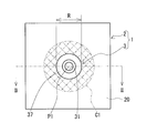
- FIG. 1 is a plan view showing a magnesium alloy member of the embodiment.
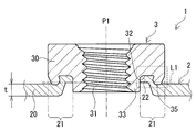
- FIG. 2A is an example of the magnesium alloy member of the embodiment shown in FIG. 1, and is a cross-sectional view taken along the II-II cutting line shown in FIG.
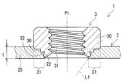
- FIG. 2B is another example of the magnesium alloy member of the embodiment shown in FIG. 1, and is a cross-sectional view taken along the II-II cutting line shown in FIG.
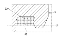
- FIG. 2C is a diagram for explaining the cross-sectional area of the groove portion of the caulking nut.
- FIG. 2D is a diagram illustrating a method of measuring the ratio of the total cross-sectional area of the gap to the cross-sectional area of the groove portion of the caulking nut.
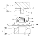
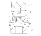
- FIG. 3A is a process diagram for explaining the method for manufacturing the magnesium alloy member of the embodiment, and is a cross-sectional view showing a preparatory process.
- FIG. 3B is a process diagram for explaining the method for manufacturing the magnesium alloy member of the embodiment, and is a cross-sectional view showing the arrangement process.
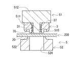
- FIG. 3C is a process diagram for explaining the method for manufacturing the magnesium alloy member of the embodiment, and is a cross-sectional view showing the initial stage of the mounting process.
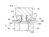
- FIG. 3D is a process diagram for explaining the method for manufacturing the magnesium alloy member of the embodiment, and is a cross-sectional view showing the latter stage of the mounting process.
- FIG. 3A is a process diagram for explaining the method for manufacturing the magnesium alloy member of the embodiment, and is a cross-sectional view showing a preparatory process.
- FIG. 3B is a process diagram for explaining the method for manufacturing the magnesium alloy member of the embodiment, and is a cross-sectional view showing the arrangement process.
- FIG. 3C is
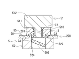
- FIG. 3E is a process diagram illustrating a method for manufacturing the magnesium alloy member of the embodiment, and is a cross-sectional view showing a mold removing step.
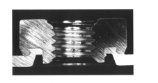
- FIG. 4 shows the sample No. of Test Example 1. It is a figure which shows the cross-sectional photograph which cut
- FIG. 5 shows the sample No. of Test Example 1. It is a figure which shows the cross-sectional photograph which cut the magnesium alloy member of 101 in the plane including the shaft of the caulking nut.
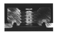
- FIG. 6 shows the sample No. of Test Example 1.
- FIG. 7 shows the sample No. of Test Example 1. It is a figure which shows the cross-sectional photograph which cut the magnesium alloy member of 102 in the plane including the shaft of the caulking nut, and is the figure which enlarges and shows the region near the groove part of the caulking nut.
- FIG. 8 is a graph showing the relationship between the processing temperature and the idling torque in the sample having the pierced nut among the samples prepared in Test Example 1.
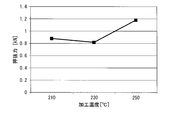
- FIG. 9 is a graph showing the relationship between the processing temperature and the punching force in the sample having the pierced nut among the samples prepared in Test Example 1.
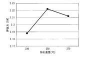
- FIG. 10 is a graph showing the relationship between the processing temperature and the idling torque in the sample having the clinching nut among the samples prepared in Test Example 1.
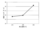
- FIG. 11 is a graph showing the relationship between the processing temperature and the punching force in the sample having the clinching nut among the samples prepared in Test Example 1.
- the caulking nut is a magnesium alloy member attached to a plate-shaped portion made of a magnesium alloy and has excellent fixing strength of the caulking nut.
- Magnesium alloys are generally inferior in plastic workability at room temperature. Therefore, when a commercially available caulking nut is attached to the magnesium alloy plate at room temperature, for example, 25 ° C., as in the case of the steel plate, the place where the caulking nut is attached and the place where the caulking nut is attached in the magnesium alloy plate and as shown in the test example described later. Cracks occur around it. Due to the cracks, the fixing strength of the caulking nut is low. Due to the low fixing strength, it is conceivable that the caulking nut will fall off from the magnesium alloy plate when the bolt is fastened to the caulking nut.
- Patent Document 2 discloses that by forming the grooves of the casting base and the nut into a specific shape as described above, the amount of plastic deformation of the casting base is reduced and the occurrence of cracks is suppressed. However, since the amount of plastic deformation of the casting base is small, the amount filled in the groove of the nut in the casting base is small. As a result, it is considered that the fixing strength between the casting base and the nut is low. In addition, both the casting base and the nut need to be molded into a specific shape. In this respect, this prior art is inferior in manufacturability of the magnesium alloy member with nut.
- one of the purposes of the present disclosure is to provide a magnesium alloy member having excellent fixing strength of the caulking nut.
- Another object of the present disclosure is to provide a method for manufacturing a magnesium alloy member to which a caulking nut can be firmly attached.
- the magnesium alloy member of the present disclosure is excellent in fixing strength of the caulking nut.
- a caulking nut can be firmly attached.
- the magnesium alloy member according to one aspect of the present disclosure is With a caulking nut With a base including a plate-shaped part, The base is made of magnesium alloy The caulking nut is attached to the plate-shaped portion and is attached to the plate-shaped portion.
- the idling torque of the caulking nut is 8.5 Nm or more.
- the magnesium alloy member according to one aspect of the present disclosure may be referred to as the first Mg alloy member.
- the plate-shaped part is unlikely to crack. Therefore, the caulking nut is prevented from falling off from the plate-shaped portion.
- Such a first Mg alloy member is excellent in fixing strength between the plate-shaped portion and the caulking nut. Further, since such a first Mg alloy member can secure a large tightening torque, a strong bolt fastening structure can be constructed.
- the magnesium alloy member according to another aspect of the present disclosure is With a caulking nut With a base including a plate-shaped part, The base is made of magnesium alloy The caulking nut is attached to the plate-shaped portion and is attached to the plate-shaped portion.
- the pushing force of the caulking nut is 0.8 kN or more.
- the magnesium alloy member according to another aspect of the present disclosure may be referred to as a second Mg alloy member.
- the second Mg alloy member even if a load along the axial direction of the caulking nut is applied to the plate-shaped portion when tightening a bolt to the caulking nut, cracks are unlikely to occur in the plate-shaped portion. Therefore, the caulking nut is prevented from falling off from the plate-shaped portion.
- Such a second Mg alloy member is excellent in fixing strength between the plate-shaped portion and the caulking nut. Further, such a second Mg alloy member is excellent in bolt fastening workability because the allowable range of the load along the axial direction is large when the bolt is fastened or the like.
- the first Mg alloy member of the present disclosure examples thereof include a form in which the pushing force of the caulking nut is 0.8 kN or more.
- the caulking nut has a tubular portion provided with a screw hole and a groove portion, and has a tubular portion.
- the groove portion is provided in the tubular portion so as to bite the region on the screw hole side of the plate-shaped portion.
- the plate-shaped portion includes a filling portion that enters the groove portion.
- the plate-shaped portion includes a portion that overlaps the crimping nut in a plan view from the axial direction of the caulking nut.
- the portion overlapping the caulking nut may be in a form having no crack.
- the above cracks may occur when installing the caulking nut. If there is no such crack, the above-mentioned crack does not develop and a large crack does not occur when the above-mentioned rotational force at the time of fastening or a load along the axial direction of the caulking nut is applied to the plate-shaped portion. Therefore, the above-mentioned form can more reliably prevent the caulking nut from falling off from the plate-shaped portion.
- Examples of the magnesium alloy include a form containing 7.2% by mass or more of Al.
- a magnesium alloy having an Al content of 7.2% by mass or more is excellent in strength, rigidity, and corrosion resistance as compared with a case where the Al content is less than 7.2% by mass. Therefore, the above form is excellent in strength, rigidity, and corrosion resistance.
- the nominal diameter of the caulking nut may be M4 or more and M12 or less specified in JIS B 1180: 2014.
- the above form is excellent in manufacturability because a commercially available caulking nut can be used.
- the method for manufacturing a magnesium alloy member according to one aspect of the present disclosure is as follows. A step of driving a caulking nut into the plate-shaped portion by a punch while the material having the plate-shaped portion is supported by a die is provided. The material is composed of a magnesium alloy. The step is performed in a state where the material, the die and the punch are heated to a warm region of the magnesium alloy.
- the method for producing a magnesium alloy member according to one aspect of the present disclosure may be referred to as the present production method.
- a caulking nut can be firmly attached to a material made of magnesium alloy.
- the reason for this is that the plastic workability of the material is enhanced by heating both the material and the die and punch, which are dies, to the warm region of the magnesium alloy.
- this manufacturing method it is not necessary to mold the material and the caulking nut into a special shape.
- a general magnesium alloy plate and a commercially available caulking nut can be used. In this respect, this manufacturing method can produce a magnesium alloy member having excellent fixing strength of the caulking nut with high productivity.
- Examples of the warm range include a form in which the temperature is 200 ° C. or higher and 280 ° C. or lower.
- step 10 As an example of the manufacturing method of the magnesium alloy member of the present disclosure, there is a form in which the caulking nut is heated to the warm region.
- the temperature of the material does not easily drop when the material comes into contact with the caulking nut. Therefore, the temperature of the material is appropriately maintained in the warm range of the magnesium alloy. Therefore, the above-mentioned form can enhance the plastic workability of the material.
- FIG. 1 is a plan view of the magnesium alloy member 1 of the embodiment in the axial direction of the caulking nut 3.
- the axial direction of the caulking nut 3 corresponds to the vertical direction on the paper surface in FIG. 2A and 2B are cross-sectional views of the magnesium alloy member 1 of the embodiment cut along a plane including the shaft P1 of the caulking nut 3.
- the plane including the shaft P1 is a plane parallel to the shaft P1 and passes through the shaft P1 of the caulking nut 3.
- the magnesium alloy member 1 of the embodiment includes a base 2 and a caulking nut 3.
- the base 2 is made of a magnesium alloy.
- the base portion 2 includes a plate-shaped portion 20.
- the caulking nut 3 is attached to the plate-shaped portion 20 by locally biting the plate-shaped portion 20.
- the caulking nut 3 is firmly attached to the plate-shaped portion 20.
- the magnesium alloy constituting the base 2 contains an additive element, and the balance is composed of Mg (magnesium) and unavoidable impurities, and is an alloy containing the largest amount of Mg.
- the additive elements are, for example, Al (aluminum), Zn (zinc), Mn (manganese), Si (silicon), Be (berylium), Ca (calcium), Sr (strontium), Y (yttrium), Li (lithium). , Zr (zirconium), Ce (cerium), and one or more elements selected from the group consisting of rare earth elements excluding Y and Ce.
- magnesium alloys containing Al are excellent in mechanical properties such as strength and rigidity, and corrosion resistance.
- the Al content is, for example, 0.1% by mass or more and 12% by mass or less.
- a magnesium alloy containing 7.2% by mass or more of Al is excellent in strength, rigidity, and corrosion resistance as compared with the case where the Al content is less than 7.2% by mass. Therefore, the magnesium alloy member 1 including the base portion 2 made of a magnesium alloy containing 7.2% by mass or more of Al is excellent in strength, rigidity, and corrosion resistance.
- the magnesium alloy member 1 including the base portion 2 made of a magnesium alloy containing Al in the above range is excellent in manufacturability because the caulking nut 3 can be easily attached in the manufacturing process.
- each additive element other than Al is, for example, 0.01% by mass or more and 10% by mass or less, and further 0.1% by mass or more and 5% by mass or less.
- magnesium alloy an alloy having a known composition, for example, various alloys specified in ASTM standard can be used.
- examples of magnesium alloys containing Al include AZ alloys, AM alloys, AS alloys and the like.
- examples of the magnesium alloy containing Zn and Zr include ZK-based alloys.
- Examples of the AZ alloy containing 7.2% by mass or more of Al include AZ31, AZ61, and AZ91.
- the base 2 includes a plate-shaped portion 20. As shown in FIGS. 2A and 2B, the plate-shaped portion 20 includes a mounting portion 21 where the caulking nut 3 is mounted.
- the base 2 includes a portion where the two surfaces are provided substantially in parallel and the distance between the two surfaces is substantially the same. The above two surfaces correspond to the upper surface and the lower surface in FIGS. 2A and 2B. The above distance corresponds to the thickness of the base 2.
- the plate-shaped portion 20 has substantially the same thickness except for the mounting portion 21. Details of the mounting location 21 will be described later.
- the base portion 2 may have a form in which substantially the entire base portion 2 is a plate-shaped portion 20. This form has substantially the same thickness over the entire base 2 except for the mounting location 21 of the caulking nut 3.
- the base 2 is a flat plate material, that is, a magnesium alloy plate.
- 2A and 2B illustrate the case where the base 2 is a flat plate material.
- the base portion 2 is a three-dimensional object having a bent portion or a curved portion at least a part of the base portion 2. Examples of the three-dimensional object include a box, a cylinder, and the like.
- the base portion 2 may include a portion other than the plate-shaped portion 20.
- the base portion 2 may have at least one of a locally thick portion, a locally thin portion, and a through hole in addition to the plate-shaped portion 20.
- Locally thick portions include, for example, protrusions.
- Locally thin portions include, for example, grooves and steps.
- a typical example of a magnesium alloy plate is one manufactured through a rolling process.
- the rolled magnesium alloy plate has excellent plastic workability, so that the caulking nut 3 can be attached well in the manufacturing process, has excellent mechanical properties such as strength, and easily has a uniform thickness.
- the magnesium alloy plate may be a cast material formed by a casting method such as a die casting method.
- Examples of the above-mentioned three-dimensional object include a molded body obtained by plastically working a magnesium alloy plate to form a predetermined shape. Examples of plastic working include press molding and the like.
- examples of the three-dimensional object include a cast material formed by a casting method such as a die casting method. The cast material is easy to manufacture even if it has a complicated three-dimensional shape.
- the attachment portion 21 of the caulking nut 3 is a portion of the plate-shaped portion 20 that comes into contact with the caulking nut 3 and a portion in the vicinity thereof.
- the mounting portion 21 is a portion of the plate-shaped portion 20 that is overlapped with the caulking nut 3 when the magnesium alloy member 1 is viewed in a plan view from the axial direction of the caulking nut 3. Therefore, the mounting portion 21 is provided in an annular shape along the circumferential direction of the caulking nut 3.
- the attachment portion 21 of the caulking nut 3 includes a portion where the plate-shaped portion 20 is plastically deformed by being bitten into the caulking nut 3.
- This plastically deformed portion is provided in the region of the plate-shaped portion 20 on the screw hole 31 side of the caulking nut 3. Further, at least a part of the plastically deformed portion has a shape corresponding to the outer shape of the groove portion 32 of the caulking nut 3 by entering the groove portion 32. That is, the plate-shaped portion 20 includes a filling portion 22 that enters the groove portion 32. Further, the plastically deformed portion may include a portion of the plate-shaped portion 20 that is thinner than the thickness t of a portion other than the attachment portion 21. Details of the screw hole 31 and the groove 32 of the caulking nut 3 will be described later.
- the thickness t of the portion of the plate-shaped portion 20 other than the attachment portion 21 of the caulking nut 3 is substantially equal to the thickness t 200 of the plate-shaped portion 20 of the material 200 before the caulking nut 3 is attached.
- the thickness t or the thickness t 200 may be appropriately selected within a range in which the caulking nut 3 can be attached.
- the thickness t is 0.1 mm or more and 5.0 mm or less, and further 0.3 mm or more and 4.0 mm or less.
- the magnesium alloy member 1 is excellent in manufacturability in that a commercially available caulking nut 3 can be used.
- the thickness t may be selected according to the type and size of the caulking nut 3. Examples of the size of the caulking nut 3 include a nominal diameter specified in JIS B 1180: 2014.
- the above-mentioned thickness t is an average value measured in a region near the mounting portion 21 of the caulking nut 3 in the plate-shaped portion 20.
- the neighborhood region is the following annular region.
- a circle C1 having a axis P1 of the caulking nut 3 as a center and an outer diameter R of the caulking nut 3 as a radius is taken.
- the annular region is a region obtained by removing the outer peripheral circle of the caulking nut 3 from the circle C1.
- the outer circle of the caulking nut 3 corresponds to a circle having an outer diameter R.
- three or more measurement points are taken at equal intervals in the circumferential direction, and the thickness of each measurement point is measured.
- the thickness t is a value obtained by averaging the thicknesses of three or more measurement points.
- FIG. 1 virtually shows the annular region by cross-hatching the alternate long and short dash line to the annular region.
- the caulking nut 3 is a nut that is attached by being press-fitted into a metal plate.
- the caulking nut 3 includes a tubular portion 30 provided with a screw hole 31 and a groove portion 32, as shown in FIGS. 2A, 2B, and 3A described later.
- the screw hole 31 constitutes a female screw.
- a bolt (not shown) is screwed into the screw hole 31.
- the groove portion 32 is provided in the tubular portion 30 so as to bite the region on the screw hole 31 side of the plate-shaped portion 20 described above. Further, the groove portion 32 is provided in an annular shape. Typically, the groove 32 opens in the end face 35 of the tubular portion 30 as shown in FIG. 2A.
- the groove portion 32 opens on the outer peripheral surface 36 as shown in FIG. 2B.
- the opening of the groove portion 32 is arranged so as to face the region on the screw hole 31 side of the plate-shaped portion 20.
- the groove portion 32 is filled with the metal constituting the metal plate to which the caulking nut 3 is attached, here, the magnesium alloy constituting the plate-shaped portion 20 in a plastically deformed state.
- the plastically deformed portion of the plate-shaped portion 20 constitutes the above-mentioned filling portion 22.
- Typical examples of the caulking nut 3 include piercing nuts and clinching nuts.
- piercing nut and the clinching nut commercially available products and other known ones can be used.
- FIG. 2A illustrates a pierce nut as the caulking nut 3.
- the groove portion 32 of the pierce nut is typically an annular groove that opens to the end face 35 arranged on the plate-shaped portion 20 side of the two end faces of the tubular portion 30.
- the tubular portion 30 of the pierce nut has a locally thin portion on the end face 35 side.
- the locally thin portion will be referred to as a thin cylinder portion 33.
- the end face 35 side corresponds to the lower side in FIG. 2A.
- the thin cylinder portion 33 protrudes from the end face 35.
- the thin cylinder portion 33 is used to provide a through hole in the metal plate when the pierce nut is attached to the metal plate. A part of the outer peripheral surface of the thin cylinder portion 33 is supported by the inner peripheral surface forming the through hole. As a result, the thin cylinder portion 33 is supported by the plate-shaped portion 20 with the through hole inserted.
- the groove portion 32 is filled with a metal plate, in which a region of the plate-shaped portion 20 in the vicinity of the through hole is plastically deformed and filled. It is also preferable to refer to FIG. 3A described later for the groove portion 32 and FIGS. 3C and 3D described later for the thin cylinder portion 33.
- FIG. 2B illustrates a clinching nut as the caulking nut 3.
- a part of the tubular portion 30 of the clinching nut is in a state of being inserted into a metal plate. Therefore, a part of the tubular portion 30 is covered with the metal constituting the metal plate over the entire circumference of the tubular portion 30 in the circumferential direction.
- the groove portion 32 of the clinching nut is typically an annular groove that opens on the outer peripheral surface 36 of the tubular portion 30.
- the groove portion 32 is filled with a metal plate, in which a region in the plate-shaped portion 20 in the vicinity of the above-mentioned pilot hole is plastically deformed and filled.
- the nominal diameter of the caulking nut 3 can be appropriately selected.
- the nominal diameter may be M4 or more and M12 or less specified in JIS B 1180: 2014.
- the nominal diameter may be M5 or more and M10 or less.
- the magnesium alloy member 1 provided with the caulking nut 3 having the nominal diameter of M5 or more and M10 or less can be used for a housing, a structural member, or the like.
- the nominal diameter of the caulking nut 3 is the nominal diameter of the bolt screwed into the screw hole 31.
- the number of caulking nuts 3 provided in the magnesium alloy member 1 does not matter.
- the magnesium alloy member 1 shown in FIG. 1 includes one caulking nut 3, but may include a plurality of caulking nuts 3.
- the mounting position of the caulking nut 3 provided on the magnesium alloy member 1 can be appropriately selected depending on the application and the like.
- the mounting position in FIG. 1 is an example.
- a part of the magnesium alloy constituting the base portion 2 is filled in the groove portion 32 provided in the caulking nut 3.
- the filling amount of the magnesium alloy in the groove 32 is large. That is, there is little gap provided between the filling portion 22 filled in the groove portion 32 and the inner peripheral surface of the groove portion 32. Further, it can be said that the groove portion 32 is filled with the filling portion 22. Quantitatively, for example, the following porosity is 2.5% or less.
- ⁇ Porosity> A cross section of the magnesium alloy member 1 cut along a plane including the shaft P1 of the caulking nut 3 is taken. In the cross section, as follows, obtaining the cross-sectional area S 3 of the groove 32, and the total sectional area S of the gap 9.
- the porosity (%) is the ratio of the total cross-sectional area S of the gap 9 to the cross-sectional area S 3 of the groove 32.
- the porosity (%) is calculated by (S / S 3 ) ⁇ 100.
- the cross-sectional area S 3 of the groove 32 the following linear L1, which is the area of the region surrounded by the inner peripheral surface 320 of the groove 32.
- the straight line L1 is a plane orthogonal to the axis P1 of the caulking nut 3 and is taken so as to be in contact with the surface of the filling portion 22. That is, the straight line L1 is taken so as to close the opening of the groove 32.
- the surface of the filling portion 22 is typically formed by the pushing portion 522 of the die 52 in the manufacturing process. For the push-in portion 522, refer to FIG. 3D described later.
- FIGS. 2C and 2D are cross-sectional views showing an enlarged region of the groove portion 32 and its vicinity when the caulking nut 3 is a pierce nut.
- the above-mentioned area shown in FIGS. 2C and 2D corresponds to the area surrounded by the broken line rectangle in FIG. 2A.
- a region surrounded by the inner peripheral surface 320 and the straight line L1 of the groove 32, the cross-sectional area S 3 of the area of the region lattice hatching of the two-dot chain line is given the groove 32.
- FIG. 2D illustrates a case where the groove portion 32 has a gap 9.
- the gap 9 is provided between the filling portion 22 filled in the groove portion 32 and the inner peripheral surface 320 of the groove portion 32 in the region surrounded by the straight line L1 and the inner peripheral surface 320 of the groove portion 32.
- the gap 9 is a region with a grid-like hatching of fine solid lines.
- the total area of the hatched area is the total cross-sectional area S of the gap 9.
- the total cross-sectional area S of the gap 9 can be obtained by subtracting the cross-sectional area S 22 of the filling portion 22 occupying the area surrounded by the inner peripheral surface 320 of the groove portion 32 and the straight line L1 from the cross-sectional area S 3 of the groove portion 32. Good. That is, the total cross-sectional area S of the gap 9 may be obtained by (S 3- S 22 ).
- the groove portion 32 opens in a direction substantially orthogonal to the axis P1 of the caulking nut 3 and the opening of the groove portion 32 is embedded in the base portion 2
- the straight line L1 is taken so as to close the opening of the groove 32.
- the straight line L1 is a straight line passing through the virtual surface forming the opening of the groove portion 32.
- the porosity is 2.5% or less, that is, if the ratio S / S 3 is 0.025 or less, it can be said that the groove portion 32 has substantially no gap 9 and the filling portion 22 is filled.
- the amount of plastic deformation of the plate-shaped portion 20 is large in the manufacturing process. Since the amount of plastic deformation is large, a large contact area between the plate-shaped portion 20 and the caulking nut 3 is secured. As a result, a strong meshing structure can be constructed between the plate-shaped portion 20 and the caulking nut 3. Therefore, the magnesium alloy member 1 is excellent in the fixing strength of the caulking nut 3.
- the porosity is preferably 2.0% or less, more preferably 1.5% or less, and 1.0% or less. It is more preferable that the porosity is 0%, that is, there is substantially no gap 9. 2A and 2B show a case where the porosity is 0%.
- the mounting portion 21 of the caulking nut 3 does not have a crack.
- the magnesium alloy member 1 has no cracks in the vicinity of the groove 32 in the plate-shaped portion 20, that is, inside and outside the groove 32.
- the cracks may occur when the caulking nut 3 is attached to the material 200 during the manufacturing process. If there are no cracks in the mounting portion 21 of the caulking nut 3, even if a rotational force for tightening the bolt, a load along the axial direction of the caulking nut 3, or the like is applied to the plate-shaped portion 20 including the mounting portion 21, the plate Large cracks are unlikely to occur in the shape portion 20. The reason for this is that the phenomenon that small cracks propagate and become large cracks due to the above-mentioned rotational force and load does not substantially occur. Since such a magnesium alloy member 1 can effectively prevent the caulking nut 3 from falling off from the plate-shaped portion 20 when the bolt is fastened or the like, it can be said that the caulking nut 3 is excellent in fixing strength.
- the magnesium alloy member 1 of the embodiment for example, the idling torque of the caulking nut 3 satisfies 8.5 Nm or more.
- the idling torque is 8.5 Nm or more, even if the rotational force when tightening the bolt to the caulking nut 3 is applied to the plate-shaped portion 20 including the mounting portion 21 of the caulking nut 3, the plate-shaped portion 20 is cracked. Is unlikely to occur. Therefore, the caulking nut 3 is prevented from falling off from the plate-shaped portion 20. It can be said that such a magnesium alloy member 1 is excellent in fixing strength of the caulking nut 3.
- the idling torque is 10 N ⁇ m or more, and further 15 N ⁇ m or more. If the idling torque is 20 N ⁇ m or more, and further 25 N ⁇ m or more, although it depends on the thickness t of the plate-shaped portion 20 and the size of the caulking nut 3, for example, the nominal diameter specified in JIS B 1180: 2014. , The above fixing strength is higher.
- the larger the idling torque the larger the tightening torque allowed when tightening the bolt can be secured. Since such a magnesium alloy member 1 can firmly tighten bolts, a strong bolt fastening structure can be constructed. The upper limit of the idling torque is not particularly set.
- the magnesium alloy member 1 having the above-mentioned porosity of 2.5% or less typically has an idling torque of 8.5 Nm or more.
- the magnesium alloy member 1 having no crack in the mounting portion 21 of the caulking nut 3 described above typically has an idling torque of 8.5 Nm or more.
- the idling torque is measured as follows.
- the magnesium alloy member 1 is arranged on the pedestal so that the caulking nut 3 faces upward, and the plate-shaped portion 20 is fixed.
- the caulking nut 3 is gripped with a jig.
- This jig is rotated around the axis of the caulking nut 3. That is, a rotational force that twists the caulking nut 3 is applied to the caulking nut 3.
- the rotational force is increased, and the jig is rotated until the caulking nut 3 is removed from the plate-shaped portion 20.
- the idling torque is the maximum rotational force when the caulking nut 3 is removed from the plate-shaped portion 20.
- a commercially available tool for measuring torque such as a torque wrench, can be used.
- the pushing force of the caulking nut 3 satisfies 0.8 kN or more.
- the pushing force is 1.00 kN or more, 1.10 kN or more, and 1.15 kN or more.
- the punching force should be 1.2 kN or more, and further 1.5 kN or more.
- the fixing strength is higher.
- the larger the pushing force the larger the allowable range of the load along the axial direction described above can be secured when the bolt is fastened.
- Such a magnesium alloy member 1 is excellent in bolt fastening workability. There is no particular upper limit on the pushing force.
- the magnesium alloy member 1 having the above-mentioned porosity of 2.5% or less typically has a punching force of 0.8 kN or more. The smaller the porosity, the higher the pushing force.
- the magnesium alloy member 1 having no crack in the mounting portion 21 of the caulking nut 3 described above typically has a pushing force of 0.8 kN or more.
- the pushing force is measured as follows.
- the magnesium alloy member 1 shown in FIGS. 2A and 2B is turned upside down, and the plate-shaped portion 20 is arranged on the pedestal so that the caulking nut 3 is arranged downward.
- the pedestal is provided with a through hole larger than the outer diameter R of the caulking nut 3.
- the caulking nut 3 is inserted into the through hole.
- the area around the caulking nut 3 in the plate-shaped portion 20 is supported by the area around the through hole in the pedestal. With the plate-shaped portion 20 supported by the pedestal, a load is applied to the caulking nut 3 along the shaft P1 direction by a jig.
- the jig is arranged so that the caulking nut 3 is pressed but the plate-shaped portion 20 is not pressed.
- a bolt may be screwed into the caulking nut 3 and the jig may press the head of the bolt. In this case, the load is easily transmitted to the caulking nut 3.
- the jig may press the thin cylinder portion 33.
- the pressing surface of the jig is brought into direct contact with the end surface of the thin cylinder portion 33.
- the load is increased and the load is applied until the caulking nut 3 comes off from the plate-shaped portion 20.
- the pushing force is the maximum load when the caulking nut 3 comes off.
- a commercially available clinch meter can be used for the measurement of the pressing force.
- the above-mentioned idling torque satisfies 8.5 Nm or more and the above-mentioned punching force satisfies 0.8 kN or more.
- Such a magnesium alloy member 1 has a plate shape including a mounting portion 21 of the caulking nut 3 in which a rotational force at the time of fastening the bolt and a load along the axial direction of the caulking nut 3 are applied when tightening the bolt to the caulking nut 3. Even if it is added to the portion 20, cracks are less likely to occur in the plate-shaped portion 20. Therefore, the caulking nut 3 is effectively prevented from falling off from the plate-shaped portion 20. It can be said that such a magnesium alloy member 1 is superior to the fixing strength of the caulking nut 3.
- the magnesium alloy member 1 of the embodiment is excellent in fixing strength between the caulking nut 3 attached to the plate-shaped portion 20 and the plate-shaped portion 20. This effect will be specifically described in a test example described later.
- the magnesium alloy member 1 of the above-described embodiment may be manufactured by, for example, a method of manufacturing the magnesium alloy member of the embodiment including the following mounting steps, that is, the present manufacturing method.
- ⁇ Mounting Step> With the material 200 having the plate-shaped portion 20 supported by the die 52, the caulking nut 3 is driven into the plate-shaped portion 20 by the punch 51 (see FIGS. 3C and 3D).
- the material 200 is made of a magnesium alloy.
- the mounting step is performed in a state where the material 200 having the plate-shaped portion 20 and the die 52 and the punch 51 are heated to the warm region of the magnesium alloy.
- the warm range of the magnesium alloy is a temperature above room temperature and below the recrystallization temperature of the magnesium alloy.
- the plastic workability of the material 200, particularly the plate-shaped portion 20 is improved by setting the processing temperature when the caulking nut 3 is attached to the plate-shaped portion 20 to the warm range of the magnesium alloy instead of room temperature.
- the plastic workability of the plate-shaped portion 20 can be effectively enhanced by heating both the material 200 and the die 52 and the punch 51 which are the dies 5 to the warm region of the magnesium alloy.
- the room temperature here is 20 ° C. ⁇ 15 ° C., typically 25 ° C.
- This manufacturing method typically includes the following preparation step, placement step, the above-mentioned mounting step, and mold removal step. Refer to FIGS. 3C and 3D for the mounting process.
- ⁇ Preparation Step> The above-mentioned material 200, a caulking nut 3, and a mold 5 are prepared.
- the mold 5 includes a punch 51 and a die 52. Refer to FIG. 3A for the preparation step.
- ⁇ Arrangement process> The die 52, the material 200, the caulking nut 3, and the punch 51 are arranged in this order from the bottom.
- the plate-shaped portion 20 of the material 200 is supported by the die 52.
- the caulking nut 3 is arranged at a predetermined position of the plate-shaped portion 20. When the plate-shaped portion 20 has a pilot hole, the caulking nut 3 is arranged at the position where the pilot hole is formed. Refer to FIG. 3B for the arrangement process.
- ⁇ Mold Removal Step> After attaching the caulking nut 3 to the plate-shaped portion 20 of the material 200, the mold 5 is removed from the magnesium alloy member 1. Refer to FIG. 3E for the mold removing step.
- the material 200 may include a plate-shaped portion 20.
- the material 200 is provided with a pilot hole according to the size of the caulking nut 3, if necessary. Preliminary holes (not shown) may be formed by performing appropriate machining such as punching.
- FIG. 3A illustrates a case where the pilot hole is not provided.
- caulking nut 3 For the caulking nut 3, it is advisable to refer to the above-mentioned (caulking nut) section.
- the mold 5 of this example includes a punch 51, a die 52, and a heating mechanism (not shown).
- the punch 51 of this example includes a shaft portion 510 and a main body 512.
- the die 52 of this example includes a main body 520 provided with a through hole 524 and a pushing portion 522.
- the heating mechanism may include a heating unit such as a heater and a control panel or the like of the heating unit.
- the heating unit may be built in the main body 512,520 or the like.
- the shaft portion 510 is inserted into the screw hole 31 of the caulking nut 3 and is used for positioning the main body 512 with respect to the guide and the caulking nut 3.
- the shaft portion 510 typically includes a columnar body such as a round bar having an inner diameter smaller than the minimum inner diameter of the screw hole 31.
- the length of the shaft portion 510 is such that the end face of the shaft portion 510 does not protrude from the opening of the screw hole 31 when the shaft portion 510 is inserted into the screw hole 31, or the opening. It is almost flush with the virtual surface created by.
- the main body 512 is a member that presses the caulking nut 3 against the plate-shaped portion 20.
- the main body 512 is typically a columnar body such as a columnar body having an outer diameter larger than the outer diameter of the shaft portion 510.
- the shaft portion 510 is erected on the end surface 511 arranged on the caulking nut 3 side of the main body 512.
- the end face 511 is arranged in contact with the caulking nut 3 as shown in FIGS. 3C and 3D.
- the end face 511 is used as a surface for pressing the end face 37 of the caulking nut 3.
- the main body 520 mainly supports the plate-shaped portion 20 of the material 200.
- the main body 520 of this example is a tubular body provided with a through hole 524 in the central portion.
- the through hole 524 is used to support the outer peripheral surface of the thin cylinder portion 33 of the caulking nut 3 as shown in FIG. 3C, and to discharge the chips 202 as shown in FIG. 3D.
- the chip 202 is generated when a part of the plate-shaped portion 20 is punched out by the thin cylinder portion 33 to form a through hole 201 in the plate-shaped portion 20.
- the main body 520 has an annular protrusion on the end surface on the side where the plate-shaped portion 20 of the material 200 is arranged, and on the upper surface in FIG. 3A and the like.
- An annular protrusion is provided along the periphery of the through hole 524.
- This annular protrusion is the push-in portion 522.
- the pushing portion 522 is used to push the region of the plate-shaped portion 20 in the vicinity of the above-mentioned through hole 201 into the groove portion 32 of the caulking nut 3.
- the shape of the push-in portion 522 is a truncated cone shape having a part of the through hole 524.
- the plate-shaped portion 20 of the material 200 is arranged on the pushing portion 522 of the die 52. Further, with the shaft portion 510 of the punch 51 inserted into the screw hole 31 of the caulking nut 3, the punch 51 and the caulking nut 3 are arranged in the plate-shaped portion 20. In this case, the through hole 524 of the die 52, the screw hole 31 of the caulking nut 3, and the shaft portion 510 of the punch 51 are likely to be arranged coaxially. As a result, the caulking nut 3 is attached to an appropriate position of the plate-shaped portion 20.
- the plate-shaped portion 20 of the material 200 is provided with a pilot hole in advance
- the plate-shaped portion 20 is arranged on the die 52 so that the through hole 524 of the die 52 and the pilot hole are coaxial with each other.
- the caulking nut 3 is arranged in the plate-shaped portion 20 by fitting a part of the caulking nut 3 into the prepared hole of the plate-shaped portion 20.
- the caulking nut 3 is driven into the plate-shaped portion 20 of the material 200 by the mold 5.
- the end face 37 of the caulking nut 3 is pressed against the plate-shaped portion 20 side by the end face 511 of the main body 512.
- the thin cylinder portion 33 comes into contact with a part of the plate-shaped portion 20 to press the plate-shaped portion 20.
- the punch 51 moves, the thin cylinder portion 33 enters the through hole 524 of the main body 520, and as shown in FIG. 3C, the plate-shaped portion 20 is provided with the through hole 201.
- the end face 35 of the caulking nut 3 then comes into contact with the plate-shaped portion 20. In this state, the caulking nut 3 is sandwiched between the punch 51 and the die 52 via the plate-shaped portion 20.
- the groove 32 of the caulking nut 3 approaches so as to cover the pushing portion 522 of the die 52.
- the region in the vicinity of the through hole 201 in the plate-shaped portion 20 is sandwiched between the end face 35 and the region in the vicinity thereof and the pushing portion 522.
- the region of the plate-shaped portion 20 is pushed into the pushing portion 522 and is filled in the groove portion 32. That is, the region of the plate-shaped portion 20 is narrowed down by the mold 5 and press-fitted into the caulking nut 3.
- the chips 202 generated by the formation of the through hole 201 are pushed by the thin cylinder portion 33 and the shaft portion 510, and fall from the through hole 524 of the die 52.
- the caulking nut 3 is also heated to the warm range of the magnesium alloy.
- the reason for this is that it is possible to prevent the temperature of the plate-shaped portion 20 of the material 200 in contact with the caulking nut 3 from dropping. That is, the temperature of the plate-shaped portion 20 is appropriately maintained in the warm region. As a result, the plate-shaped portion 20 can be satisfactorily plastically deformed.
- the processing temperature that is, the heating temperature of the material 200 and the mold 5, preferably the caulking nut 3, is selected within a temperature range equal to or lower than the recrystallization temperature of the magnesium alloy constituting the material 200.
- the heating temperature in the warm range of the magnesium alloy is 200 ° C. or higher and 280 ° C. or lower.
- the heating temperature is 200 ° C. or higher, the plastic workability of the material 200 is enhanced. That is, a large amount of plastic deformation is secured in the plate-shaped portion 20 of the material 200. As a result, the plate-shaped portion 20 and the caulking nut 3 are firmly engaged with each other, and the caulking nut 3 is firmly attached to the plate-shaped portion 20.
- the higher the heating temperature the higher the plastic workability of the plate-shaped portion 20 tends to be.
- the heating temperature may be, for example, 210 ° C. or higher, 220 ° C. or higher, 230 ° C. or higher, or 240 ° C. or higher.
- the heating temperature is 280 ° C or less, the material 200 is unlikely to be burned.
- the heating temperature may be, for example, 275 ° C. or lower, and further 270 ° C. or lower.
- the heating temperature is, for example, 210 ° C. or higher and 275 ° C. or lower, and further 220 ° C. or higher and 270 ° C. or lower, the fixing strength of the caulking nut 3 tends to be higher.
- the fixing strength of the caulking nut 3 tends to be higher.
- the heating temperature is preferably adjusted according to the thickness t 200 of the plate-shaped portion 20, the composition of the magnesium alloy constituting the plate-shaped portion 20, the shape and size of the caulking nut 3.
- JIS B 1180 in the caulking nut 3 on the nominal diameter defined is relatively large in 2014, if the thickness t 200 is relatively thick, the heating temperature may be at higher temperatures.
- the thickness t 200 is 1.5mm or more, if it is more 2.0mm or more, the heating temperature is, for example 230 ° C. or higher, and a higher 240 ° C..
- the temperature of at least one of the material 200, the mold 5, and the caulking nut 3 may be different, or the temperatures of all three may be substantially the same. Good. If the temperatures of the three are the same, temperature control is easy. Further, the temperature of the punch 51 and the temperature of the die 52 may be different or substantially the same. When the heating temperature is different, the temperature difference may be 30 ° C. or lower, further 25 ° C. or lower.
- the caulking nut 3 is easy to use if it is heated and held in a constant temperature bath, for example.
- the heating temperature of the caulking nut 3 is higher than the temperature of the material 200. It may be expensive.
- At least one of the material 200 and the mold 5, preferably both, may be preheated to a warm region of the magnesium alloy.
- both the mold 5 and the material 200 are preheated as compared with the case where the mold 5 and the material 200 are heated in the warm region by the heating mechanism described above.
- the installation work time can be easily shortened.
- the temperature of the material 200 tends to be uniform. Therefore, the material 200, particularly the plate-shaped portion 20, is satisfactorily plastically deformed. In these respects, the above-mentioned form of preheating can produce the magnesium alloy member 1 with high productivity.
- a magnesium alloy member 1 in which the caulking nut 3 is firmly attached to the plate-shaped portion 20 can be obtained.
- a magnesium alloy member 1 satisfying at least one of the idling torque of the caulking nut 3 being 8.5 Nm or more and the pushing force of the caulking nut 3 being 0.8 kN or more can be obtained.
- the region of the plate-shaped portion 20 in the vicinity of the above-mentioned through hole 201 includes a region on the screw hole 31 side of the caulking nut 3 and a filling portion 22 that has entered the groove portion 32.
- the caulking nut 3 is firmly attached to the plate-shaped portion 20. This effect will be specifically described in the following test examples.
- a magnesium alloy plate having a composition equivalent to that of an AZ91 alloy was prepared.
- the composition is Mg-8.7% by mass Al-0.65% by mass Zn.
- This magnesium alloy plate was manufactured by a known method including a rolling step.
- the thickness of the prepared magnesium alloy plate is 1.3 mm to 2.0 mm.
- the thickness of the magnesium alloy plate is referred to as a plate thickness.
- a caulking nut As a caulking nut, a commercially available piercing nut and a commercially available clinching nut were prepared.
- the nominal diameter of the pierce nut is M10.
- the nominal diameter of the clinching nut is M10.
- the nominal diameter is a value standardized in JIS B 1180: 2014.
- a known mold equipped with a punch and a die was used. By attaching commercially available heaters to the punch and die, respectively, the punch and die can be heated.
- the plate with nuts 101 was produced by using a magnesium alloy plate having one plate thickness selected from the group consisting of 1.3 mm, 1.4 mm, and 1.5 mm and the above-mentioned pierced nut.
- the plate thickness (mm) of each sample is shown in Table 1.
- the processing temperature at which the pierce nut was attached to the magnesium alloy plate was set to the warm range of the magnesium alloy. Specifically, the magnesium alloy plate, the pierce nut, and both the punch and the die are heated to a temperature selected from the range of 210 ° C. or higher and 270 ° C. or lower. The pierce nut was attached to the magnesium alloy plate by driving the pierce nut at the above temperature into the magnesium alloy plate with a punch at the above temperature while the magnesium alloy plate at the above temperature was supported by the die at the above temperature.
- the heating temperature of the magnesium alloy plate was 210 ° C., and the heating temperature of the pierce nut and the heating temperature of the punch and die were 250 ° C.
- the heating temperature of the magnesium alloy plate was 230 ° C., and the heating temperature of the pierce nut and the heating temperature of the punch and die were 250 ° C.
- Sample No. 1 to No. In No. 5 the heating temperature (° C.) of the magnesium alloy plate, the pierce nut, and the mold was set to the processing temperature (° C.) shown in Table 1.
- the magnesium alloy plate, the pierce nut, and the die were heated to 250 ° C.
- the punch temperature was set to room temperature
- the pierce nut was attached to the magnesium alloy plate. That is, a part of the mold, here the punch, is not heated to the warm region of the magnesium alloy.
- the room temperature here is 25 ° C.
- the plate with nuts of 102 was produced by using a magnesium alloy plate having a plate thickness of 1.4 mm or 2.0 mm and the above-mentioned clinching nut.
- Table 2 shows the plate thickness (mm) of each sample.
- the processing temperature at which the clinching nut was attached to the magnesium alloy plate was set to the warm range of the magnesium alloy. Specifically, the magnesium alloy plate, the clinching nut, and both the punch and the die are heated to a temperature selected from the range of 210 ° C. or higher and 250 ° C. or lower. The clinching nut was attached to the magnesium alloy plate by driving the clinching nut at the above temperature into the magnesium alloy plate with a punch at the above temperature while the magnesium alloy plate at the above temperature was supported by the die at the above temperature. .. Sample No. 22-No. In No. 24, the heating temperature (° C.) of the magnesium alloy plate, the clinching nut, and the mold was set to the processing temperature (° C.) shown in Table 2.
- Sample No. In 102 the clinching nut was attached to the magnesium alloy plate with the temperatures of the magnesium alloy plate, the clinching nut, and the mold set to room temperature. That is, none of the above three is heated to the warm region of the magnesium alloy.
- the room temperature here is 25 ° C.
- the idling torque is measured as described above. Briefly, the nut-attached plate is placed on the pedestal so that the caulking nut is placed facing up. Grasp the caulking nut with a jig and rotate the caulking nut around its axis. Increase the rotational force until the caulking nut comes off the magnesium alloy plate. The idling torque is the maximum rotational force when the caulking nut is removed from the magnesium alloy plate.
- the idling torque was measured using a commercially available torque wrench. Further, here, 10 samples were prepared for each sample. The idling torques of 10 samples were measured, and the averaged values are shown in Tables 1 and 2 as the idling torques of each sample.
- the pushing force is measured as described above. Briefly, the nut-attached plate is placed on the pedestal so that the caulking nut is placed facing down. A jig is brought into contact with the end face of the caulking nut, and a load is applied along the axial direction of the caulking nut. Increase the load until the caulking nut comes off the magnesium alloy plate. The pushing force is the maximum load when the caulking nut comes off.
- the pushing force was measured using a commercially available clinch meter. Further, here, 10 samples were prepared for each sample. The punching force of 10 samples was measured, and the averaged values are shown in Tables 1 and 2 as the punching force of each sample.
- Sample No. 1 to No. 7, No. 21-No. All of the 24 nut-attached plates have an idling torque of 8.5 Nm or more.
- sample No. 1 to No. 7, No. 21-No. All of the 24 nut-attached plates have a pushing force of 0.8 kN or more.
- sample No. 1 to No. 7, No. 21-No. 24 is called a specific sample group.
- the idling torque of the specific sample group is 10 N ⁇ m or more and 12 N ⁇ m or more.
- the punching force is 1.0 kN or more. Therefore, in many of the specific sample groups, the caulking nut is firmly fixed by the magnesium alloy plate, and it can be said that the caulking nut is superior in fixing strength.
- the specific sample group equipped with the piercing nut has higher idling torque and pushing force than the specific sample group equipped with the clinching nut.
- the punching force is 1.5 kN or more, further 1.9 kN or more, and most samples are 2.0 kN or more.
- sample No. 101, No. All of the 102 nut-attached plates have an idling torque of 8.3 Nm or less and a pushing force of less than 0.1 kN.
- the reason for the difference in the fixing strength of the caulking nut is that, as shown in FIGS. 4 to 7, the properties of the nut-attached plates that come into contact with the caulking nuts in the magnesium alloy plate, that is, the caulking nut mounting locations, are different. Can be considered.
- the sample No. which is a specific sample group. 2, No. In No. 24, the plate with nut does not have a crack at the mounting location of the caulking nut.
- the contact area between the magnesium alloy plate and the caulking nut is large, and it can be said that they are in close contact with each other.
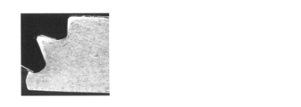
- the sample No. 101, No. In 102 a crack is generated at the mounting location of the caulking nut.
- Sample No. In 101 cracks are formed so as to divide the front and back surfaces of the magnesium alloy plate.
- sample No. In 101 due to this crack, the end face of the caulking nut is not in contact with the magnesium alloy plate, and a large gap is formed between the end face and the magnesium alloy plate.
- Sample No. In 102 the filling portion to be filled in the groove portion of the caulking nut in the magnesium alloy plate is divided into a plurality of parts by the crack, and a large gap 9 is formed between the groove portion and the filling portion.
- Porosity is the ratio of the total cross-sectional area of the gap to the cross-sectional area of the groove of the caulking nut.
- the total cross-sectional area of the gap is the gap provided between the filling portion filled in the groove portion of the caulking nut and the inner peripheral surface of the groove portion in the region surrounded by the straight line L1 and the inner peripheral surface of the groove portion as described above. It is the sum of the cross-sectional areas of.
- the porosity of the specific sample group is 0%. That is, in the specific sample group, it can be said that a part of the magnesium alloy plate is filled in the groove of the caulking nut with substantially no gap.
- sample No. The porosity of 102 is 30% or more, which is very large.
- Sample No. The porosity of 101 is 2.7%.
- the idling torque is 25 N ⁇ m or more and the pushing force is 2.18 kN or more, both of which are high. Therefore, according to the tendency of the graphs of FIGS. 8 and 9, in the range of 200 ° C. or higher and 280 ° C. or lower including the above temperature range, the magnesium alloy member having an idling torque of 8.5 Nm or higher and a punching force of 0. It is considered that a magnesium alloy member having a value of .8 kN or more can be obtained more reliably.
- a magnesium alloy member in which a caulking nut is attached to a plate-shaped portion made of a magnesium alloy, which has a high idling torque and a high punching force and is excellent in fixing strength of the caulking nut. It was.
- Such a magnesium alloy member is lighter than the case where the plate-shaped portion is made of an iron-based material such as steel. Therefore, this magnesium alloy member can be suitably used as a lightweight member having screw holes.
- the magnesium alloy member having excellent fixing strength of the above-mentioned caulking nut is manufactured by setting the processing temperature when attaching the caulking nut to the warm range of the magnesium alloy.
- Test Example 1 the composition of the magnesium alloy, the thickness of the magnesium alloy plate, the nominal diameter of the caulking nut, and the like can be appropriately changed.
Landscapes
- Engineering & Computer Science (AREA)
- Chemical & Material Sciences (AREA)
- Mechanical Engineering (AREA)
- General Engineering & Computer Science (AREA)
- Materials Engineering (AREA)
- Metallurgy (AREA)
- Organic Chemistry (AREA)
- Connection Of Plates (AREA)
- Forging (AREA)
Abstract
かしめナットと、板状部を含む基部とを備え、前記基部は、マグネシウム合金から構成され、前記かしめナットは、前記板状部に取り付けられており、前記かしめナットの空転トルクが8.5N・m以上である、マグネシウム合金部材。
Description
本開示は、マグネシウム合金部材、及びマグネシウム合金部材の製造方法に関する。
本出願は、2019年06月28日付の日本国出願の特願2019-121651に基づく優先権を主張し、前記日本国出願に記載された全ての記載内容を援用するものである。
本出願は、2019年06月28日付の日本国出願の特願2019-121651に基づく優先権を主張し、前記日本国出願に記載された全ての記載内容を援用するものである。
従来、鋼板に雌ねじを形成する方法として、ピアスナットやクリンチングナットと呼ばれるかしめナットを鋼板に取り付けることがなされている。特許文献1はピアスナットを鋼板に取り付けることを開示する。
特許文献2は、マグネシウム合金からなる板状の鋳造基台に、ナットをかしめ付けた構造を開示する。鋳造基台におけるナットが取り付けられる箇所には、予め円筒状の凸部が形成される。ナットにおける鋳造基台に取り付けられる箇所には、特定の形状の溝が予め形成される。
本開示のマグネシウム合金部材は、
かしめナットと、
板状部を含む基部とを備え、
前記基部は、マグネシウム合金から構成され、
前記かしめナットは、前記板状部に取り付けられており、
前記かしめナットの空転トルクが8.5N・m以上である。
かしめナットと、
板状部を含む基部とを備え、
前記基部は、マグネシウム合金から構成され、
前記かしめナットは、前記板状部に取り付けられており、
前記かしめナットの空転トルクが8.5N・m以上である。
別の本開示のマグネシウム合金部材は、
かしめナットと、
板状部を含む基部とを備え、
前記基部は、マグネシウム合金から構成され、
前記かしめナットは、前記板状部に取り付けられており、
前記かしめナットの押抜力が0.8kN以上である。
かしめナットと、
板状部を含む基部とを備え、
前記基部は、マグネシウム合金から構成され、
前記かしめナットは、前記板状部に取り付けられており、
前記かしめナットの押抜力が0.8kN以上である。
本開示のマグネシウム合金部材の製造方法は、
板状部を有する素材がダイで支持された状態で、パンチによって、かしめナットを前記板状部に打ち込む工程を備え、
前記素材は、マグネシウム合金から構成されており、
前記工程は、前記素材と、前記ダイ及び前記パンチとを前記マグネシウム合金の温間域に加熱した状態で行う。
板状部を有する素材がダイで支持された状態で、パンチによって、かしめナットを前記板状部に打ち込む工程を備え、
前記素材は、マグネシウム合金から構成されており、
前記工程は、前記素材と、前記ダイ及び前記パンチとを前記マグネシウム合金の温間域に加熱した状態で行う。
[本開示が解決しようとする課題]
かしめナットがマグネシウム合金からなる板状の部分に取り付けられたマグネシウム合金部材であって、かしめナットの固定強度に優れるものが望まれている。
かしめナットがマグネシウム合金からなる板状の部分に取り付けられたマグネシウム合金部材であって、かしめナットの固定強度に優れるものが望まれている。
マグネシウム合金は、一般に、室温での塑性加工性に劣る。そのため、マグネシウム合金板に対して、鋼板と同様に、室温、例えば25℃で市販のかしめナットが取り付けられると、後述の試験例に示すように、マグネシウム合金板におけるかしめナットが取り付けられた箇所及びその周辺に亀裂が生じる。亀裂があることで、かしめナットの固定強度が低い。固定強度が低いことで、かしめナットにボルトを締結する際に、かしめナットがマグネシウム合金板から脱落することが考えられる。
特許文献2は、上述のように鋳造基台及びナットの溝を特定の形状にすることで、鋳造基台の塑性変形量を僅かにして、亀裂の発生を抑制することを開示する。しかし、鋳造基台の塑性変形量が小さいため、鋳造基台におけるナットの溝に充填される量が少なくなる。その結果、鋳造基台とナットとの固定強度が低いと考えられる。また、鋳造基台もナットも特定の形状に成形する必要がある。この点で、この従来技術は、ナット付きマグネシウム合金部材の製造性に劣る。
そこで、本開示は、かしめナットの固定強度に優れるマグネシウム合金部材を提供することを目的の一つとする。また、本開示は、かしめナットを強固に取り付けられるマグネシウム合金部材の製造方法を提供することを他の目的とする。
[本開示の効果]
本開示のマグネシウム合金部材は、かしめナットの固定強度に優れる。本開示のマグネシウム合金部材の製造方法は、かしめナットを強固に取り付けられる。
本開示のマグネシウム合金部材は、かしめナットの固定強度に優れる。本開示のマグネシウム合金部材の製造方法は、かしめナットを強固に取り付けられる。
[本開示の実施形態の説明]
最初に本開示の実施態様を列記して説明する。
(1)本開示の一態様に係るマグネシウム合金部材は、
かしめナットと、
板状部を含む基部とを備え、
前記基部は、マグネシウム合金から構成され、
前記かしめナットは、前記板状部に取り付けられており、
前記かしめナットの空転トルクが8.5N・m以上である。
以下、本開示の一態様に係るマグネシウム合金部材を第一のMg合金部材と呼ぶことがある。
最初に本開示の実施態様を列記して説明する。
(1)本開示の一態様に係るマグネシウム合金部材は、
かしめナットと、
板状部を含む基部とを備え、
前記基部は、マグネシウム合金から構成され、
前記かしめナットは、前記板状部に取り付けられており、
前記かしめナットの空転トルクが8.5N・m以上である。
以下、本開示の一態様に係るマグネシウム合金部材を第一のMg合金部材と呼ぶことがある。
第一のMg合金部材では、かしめナットにボルトを締め付ける際の回転力が板状部に加えられても、板状部に亀裂が生じ難い。そのため、かしめナットが板状部から脱落することが防止される。このような第一のMg合金部材は、板状部とかしめナットとの固定強度に優れる。また、このような第一のMg合金部材は、締付トルクを大きく確保できるため、強固なボルト締結構造を構築できる。
(2)本開示の別の態様に係るマグネシウム合金部材は、
かしめナットと、
板状部を含む基部とを備え、
前記基部は、マグネシウム合金から構成され、
前記かしめナットは、前記板状部に取り付けられており、
前記かしめナットの押抜力が0.8kN以上である。
以下、本開示の別の態様に係るマグネシウム合金部材を第二のMg合金部材と呼ぶことがある。
かしめナットと、
板状部を含む基部とを備え、
前記基部は、マグネシウム合金から構成され、
前記かしめナットは、前記板状部に取り付けられており、
前記かしめナットの押抜力が0.8kN以上である。
以下、本開示の別の態様に係るマグネシウム合金部材を第二のMg合金部材と呼ぶことがある。
第二のMg合金部材では、かしめナットにボルトを締め付ける際等にかしめナットの軸方向に沿った荷重が板状部に加えられても、板状部に亀裂が生じ難い。そのため、かしめナットが板状部から脱落することが防止される。このような第二のMg合金部材は、板状部とかしめナットとの固定強度に優れる。また、このような第二のMg合金部材は、ボルトの締結時等において上記軸方向に沿った荷重の許容範囲が大きいため、ボルトの締結作業性に優れる。
(3)本開示の第一のMg合金部材の一例として、
前記かしめナットの押抜力が0.8kN以上である形態が挙げられる。
前記かしめナットの押抜力が0.8kN以上である形態が挙げられる。
上記形態では、かしめナットにボルトを締め付ける際等にかしめナットの軸方向に沿った荷重が板状部に加えられても、板状部に亀裂が生じ難い。このような上記形態は、かしめナットの固定強度により優れる。また、上記形態は、ボルトの締結時等における上記荷重の許容範囲が大きいため、ボルトの締結作業性に優れる。
(4)本開示の第一のMg合金部材又は第二のMg合金部材の一例として、
前記かしめナットは、ねじ孔と、溝部とが設けられた筒状部を備え、
前記溝部は、前記板状部における前記ねじ孔側の領域をかみ込むように、前記筒状部に設けられており、
前記板状部は、前記溝部に入り込む充填部を含み、
前記かしめナットの軸を含む平面で切断した断面において、
前記溝部の開口部を塞ぐように直線L1をとり、前記直線L1と前記溝部の内周面とで囲まれる領域の断面積を前記溝部の断面積S3とし、前記領域において、前記充填部と前記内周面との間に設けられる隙間の合計断面積をSとし、前記溝部の断面積S3に対する前記隙間の合計断面積Sの割合S/S3が0.025以下である形態が挙げられる。
前記かしめナットは、ねじ孔と、溝部とが設けられた筒状部を備え、
前記溝部は、前記板状部における前記ねじ孔側の領域をかみ込むように、前記筒状部に設けられており、
前記板状部は、前記溝部に入り込む充填部を含み、
前記かしめナットの軸を含む平面で切断した断面において、
前記溝部の開口部を塞ぐように直線L1をとり、前記直線L1と前記溝部の内周面とで囲まれる領域の断面積を前記溝部の断面積S3とし、前記領域において、前記充填部と前記内周面との間に設けられる隙間の合計断面積をSとし、前記溝部の断面積S3に対する前記隙間の合計断面積Sの割合S/S3が0.025以下である形態が挙げられる。
上記形態は、板状部の一部がかしめナットの溝部に実質的に隙間なく充填されているといえる。つまり、板状部の塑性変形量が多い。このような上記形態は、かしめナットの固定強度に優れる。
(5)本開示の第一のMg合金部材又は第二のMg合金部材の一例として、
前記板状部は、前記かしめナットの軸方向からの平面視で、前記かしめナットに重複して配置される箇所を備え、
前記かしめナットの軸を含む平面で切断した断面において、
前記かしめナットに重複して配置される箇所は、亀裂を有さない形態が挙げられる。
前記板状部は、前記かしめナットの軸方向からの平面視で、前記かしめナットに重複して配置される箇所を備え、
前記かしめナットの軸を含む平面で切断した断面において、
前記かしめナットに重複して配置される箇所は、亀裂を有さない形態が挙げられる。
上記亀裂は、かしめナットを取り付ける際に生じ得る。上記亀裂が無ければ、上述の締結時の回転力や、かしめナットの軸方向に沿った荷重が板状部に加えられた際に、上記亀裂が進展して大きな亀裂が生じることがない。従って、上記形態は、かしめナットが板状部から脱落することをより確実に防止できる。
(6)本開示の第一のMg合金部材又は第二のMg合金部材の一例として、
前記マグネシウム合金は、Alを7.2質量%以上含む形態が挙げられる。
前記マグネシウム合金は、Alを7.2質量%以上含む形態が挙げられる。
Alの含有量が7.2質量%以上であるマグネシウム合金は、Alの含有量が7.2質量%未満である場合に比較して、強度、剛性、耐食性に優れる。従って、上記形態は、強度、剛性、耐食性に優れる。
(7)本開示の第一のMg合金部材又は第二のMg合金部材の一例として、
前記かしめナットの呼び径は、JIS B 1180:2014に規定されるM4以上M12以下である形態が挙げられる。
前記かしめナットの呼び径は、JIS B 1180:2014に規定されるM4以上M12以下である形態が挙げられる。
上記形態は、市販のかしめナットを利用できるため、製造性に優れる。
(8)本開示の一態様に係るマグネシウム合金部材の製造方法は、
板状部を有する素材がダイで支持された状態で、パンチによって、かしめナットを前記板状部に打ち込む工程を備え、
前記素材は、マグネシウム合金から構成されており、
前記工程は、前記素材と、前記ダイ及び前記パンチとを前記マグネシウム合金の温間域に加熱した状態で行う。
以下、本開示の一態様に係るマグネシウム合金部材の製造方法を本製法と呼ぶことがある。
板状部を有する素材がダイで支持された状態で、パンチによって、かしめナットを前記板状部に打ち込む工程を備え、
前記素材は、マグネシウム合金から構成されており、
前記工程は、前記素材と、前記ダイ及び前記パンチとを前記マグネシウム合金の温間域に加熱した状態で行う。
以下、本開示の一態様に係るマグネシウム合金部材の製造方法を本製法と呼ぶことがある。
本製法は、マグネシウム合金からなる素材にかしめナットを強固に取り付けられる。この理由は、素材と、金型であるダイ及びパンチとの双方がマグネシウム合金の温間域に加熱されることで、素材の塑性加工性が高められるからである。また、本製法を利用すれば、素材及びかしめナットを特別な形状に成形する必要がない。本製法は、一般的なマグネシウム合金板及び市販のかしめナットを利用できる。この点で、本製法は、かしめナットの固定強度に優れるマグネシウム合金部材を生産性よく製造できる。
(9)本開示のマグネシウム合金部材の製造方法の一例として、
前記温間域は、200℃以上280℃以下である形態が挙げられる。
前記温間域は、200℃以上280℃以下である形態が挙げられる。
上記形態は、かしめナットの固定強度をより高め易い。
(10)本開示のマグネシウム合金部材の製造方法の一例として、
前記工程では、前記かしめナットを前記温間域に加熱する形態が挙げられる。
前記工程では、前記かしめナットを前記温間域に加熱する形態が挙げられる。
上記形態では、素材がかしめナットに接触した際に素材の温度が低下し難い。そのため、素材の温度がマグネシウム合金の温間域に適切に保持される。従って、上記形態は、素材の塑性加工性を高められる。
[本開示の実施形態の詳細]
以下、図面を参照して、本開示の実施の形態を詳細に説明する。図中の同一符号は、同一名称物を示す。
以下、図面を参照して、本開示の実施の形態を詳細に説明する。図中の同一符号は、同一名称物を示す。
[マグネシウム合金部材]
以下、主に図1,図2A,図2Bを参照して、実施形態に係るマグネシウム合金部材を説明する。
図1は、実施形態のマグネシウム合金部材1をかしめナット3の軸方向に平面視した図である。なお、かしめナット3の軸方向は、図1では紙面垂直方向に相当する。
図2A,図2Bは、実施形態のマグネシウム合金部材1を、かしめナット3の軸P1を含む平面で切断した断面図である。軸P1を含む平面は、軸P1に平行な面であって、かしめナット3の軸P1を通る面である。
以下、主に図1,図2A,図2Bを参照して、実施形態に係るマグネシウム合金部材を説明する。
図1は、実施形態のマグネシウム合金部材1をかしめナット3の軸方向に平面視した図である。なお、かしめナット3の軸方向は、図1では紙面垂直方向に相当する。
図2A,図2Bは、実施形態のマグネシウム合金部材1を、かしめナット3の軸P1を含む平面で切断した断面図である。軸P1を含む平面は、軸P1に平行な面であって、かしめナット3の軸P1を通る面である。
(概要)
実施形態のマグネシウム合金部材1は、基部2と、かしめナット3とを備える。基部2は、マグネシウム合金から構成される。また、基部2は、板状部20を含む。かしめナット3は、板状部20を局所的にかみ込むことで、板状部20に取り付けられる。特に、実施形態のマグネシウム合金部材1では、かしめナット3が板状部20に強固に取り付けられている。
以下、より詳細に説明する。
実施形態のマグネシウム合金部材1は、基部2と、かしめナット3とを備える。基部2は、マグネシウム合金から構成される。また、基部2は、板状部20を含む。かしめナット3は、板状部20を局所的にかみ込むことで、板状部20に取り付けられる。特に、実施形態のマグネシウム合金部材1では、かしめナット3が板状部20に強固に取り付けられている。
以下、より詳細に説明する。
(基部)
〈組成〉
基部2を構成するマグネシウム合金は、添加元素を含み、残部がMg(マグネシウム)及び不可避不純物からなり、Mgを最も多く含む合金である。添加元素は、例えば、Al(アルミニウム),Zn(亜鉛),Mn(マンガン),Si(ケイ素),Be(ベリリウム),Ca(カルシウム),Sr(ストロンチウム),Y(イットリウム),Li(リチウム),Zr(ジルコニウム),Ce(セリウム),及びY,Ceを除く希土類元素からなる群より選択された1種以上の元素が挙げられる。
〈組成〉
基部2を構成するマグネシウム合金は、添加元素を含み、残部がMg(マグネシウム)及び不可避不純物からなり、Mgを最も多く含む合金である。添加元素は、例えば、Al(アルミニウム),Zn(亜鉛),Mn(マンガン),Si(ケイ素),Be(ベリリウム),Ca(カルシウム),Sr(ストロンチウム),Y(イットリウム),Li(リチウム),Zr(ジルコニウム),Ce(セリウム),及びY,Ceを除く希土類元素からなる群より選択された1種以上の元素が挙げられる。
特に、Alを含むマグネシウム合金は、強度や剛性といった機械的特性、耐食性に優れる。Alの含有量は、例えば0.1質量%以上12質量%以下が挙げられる。特に、Alを7.2質量%以上含むマグネシウム合金は、Alの含有量が7.2質量%未満である場合に比較して、強度や剛性、耐食性に優れる。そのため、Alを7.2質量%以上含むマグネシウム合金から構成される基部2を備えるマグネシウム合金部材1は、強度や剛性、耐食性により優れる。
Alの含有量が多いほど、マグネシウム合金は機械的特性及び耐食性に優れる。特に、Alの含有量が8.3質量%以上9.5質量%以下であるマグネシウム合金は、機械的特性及び耐食性に優れる上に、Alの含有量が多い中では塑性加工性にも優れる。そのため、Alを上記範囲で含むマグネシウム合金から構成される基部2を備えるマグネシウム合金部材1は、製造過程でかしめナット3を取り付け易い点から、製造性に優れる。
Al以外の各添加元素の含有量は、例えば、0.01質量%以上10質量%以下、更に0.1質量%以上5質量%以下が挙げられる。
マグネシウム合金は、公知の組成の合金、例えばASTM規格に規定される各種の合金を利用できる。ASTM規格に規定されるマグネシウム合金のうち、Alを含むマグネシウム合金は、例えばAZ系合金、AM系合金、AS系合金等が挙げられる。ZnとZrとを含むマグネシウム合金は、例えばZK系合金等が挙げられる。Alを7.2質量%以上含むAZ系合金は、例えばAZ31,AZ61,AZ91等が挙げられる。
〈形状〉
《板状部》
基部2は、板状部20を含む。板状部20は、図2A,図2Bに示すように、かしめナット3が取り付けられた箇所である取付箇所21を含む。ここで、基部2は、二つの面が実質的に平行に設けられると共に、両面間の距離が実質的に同じ箇所を含む。上記二つの面は、図2A,図2Bでは上面及び下面に相当する。上記距離は基部2の厚さに相当する。板状部20は、取付箇所21を除いて、上記厚さが実質的に同じ箇所である。取付箇所21の詳細は、後述する。
《板状部》
基部2は、板状部20を含む。板状部20は、図2A,図2Bに示すように、かしめナット3が取り付けられた箇所である取付箇所21を含む。ここで、基部2は、二つの面が実質的に平行に設けられると共に、両面間の距離が実質的に同じ箇所を含む。上記二つの面は、図2A,図2Bでは上面及び下面に相当する。上記距離は基部2の厚さに相当する。板状部20は、取付箇所21を除いて、上記厚さが実質的に同じ箇所である。取付箇所21の詳細は、後述する。
基部2は、例えば、その実質的に全体が板状部20である形態が挙げられる。この形態は、かしめナット3の取付箇所21を除き、基部2の全体にわたって実質的に同じ厚さを有する。この形態の一例として、基部2が平坦な板材であること、即ちマグネシウム合金板であることが挙げられる。図2A,図2Bは、基部2が平坦な板材である場合を例示する。図示しないが、この形態の別例として、基部2が、基部2の少なくとも一部に屈曲部や湾曲部を有する立体物であることが挙げられる。上記立体物は、例えば、箱、円筒等が挙げられる。
その他、基部2は、板状部20ではない箇所を含んでもよい。図示しないが、例えば、基部2は、板状部20に加えて、局所的に厚い部分、局所的に薄い部分、及び貫通孔の少なくとも一つを有してもよい。局所的に厚い部分は、例えば突起が挙げられる。局所的に薄い部分は、例えば溝、段差が挙げられる。
マグネシウム合金板は、代表的には、圧延工程を経て製造されたものが挙げられる。圧延を経たマグネシウム合金板は、塑性加工性に優れることで製造過程ではかしめナット3を良好に取り付けられる、強度といった機械的特性に優れる、均一的な厚さを有し易い等の効果を奏する。又は、マグネシウム合金板は、ダイカスト法といった鋳造法によって成形された鋳造材でもよい。
上述の立体物は、例えば、マグネシウム合金板に塑性加工が施されて所定の形状に成形された成形体が挙げられる。塑性加工は例えばプレス成形等が挙げられる。又は、上記立体物は、ダイカスト法等といった鋳造法によって成形された鋳造材等が挙げられる。鋳造材は、複雑な立体形状であっても、製造し易い。
《かしめナットの取付箇所》
かしめナット3の取付箇所21は、板状部20において、かしめナット3に接触する箇所及びその近傍の箇所である。具体的には、取付箇所21は、マグネシウム合金部材1をかしめナット3の軸方向から平面視した場合に、板状部20においてかしめナット3に重複して配置される箇所である。そのため、取付箇所21は、かしめナット3の周方向に沿って環状に設けられる。
かしめナット3の取付箇所21は、板状部20において、かしめナット3に接触する箇所及びその近傍の箇所である。具体的には、取付箇所21は、マグネシウム合金部材1をかしめナット3の軸方向から平面視した場合に、板状部20においてかしめナット3に重複して配置される箇所である。そのため、取付箇所21は、かしめナット3の周方向に沿って環状に設けられる。
かしめナット3の取付箇所21は、かしめナット3にかみ込まれることで板状部20が塑性変形した部分を含む。この塑性変形部分は、板状部20におけるかしめナット3のねじ孔31側の領域に設けられる。また、上記塑性変形部分の少なくとも一部は、溝部32に入り込むことで、かしめナット3の溝部32の外形に対応した形状を有する。即ち、板状部20は、溝部32に入り込む充填部22を備える。また、上記塑性変形部分は、板状部20における取付箇所21以外の箇所の厚さtよりも薄い部分を含み得る。かしめナット3のねじ孔31、溝部32の詳細は後述する。
〈厚さ〉
板状部20におけるかしめナット3の取付箇所21以外の箇所の厚さtは、かしめナット3が取り付けられる前の素材200における板状部20の厚さt200に実質的に等しい。素材200は後述の図3Aを参照するとよい。厚さt又は厚さt200は、かしめナット3を取り付け可能な範囲で適宜選択するとよい。例えば、厚さtは0.1mm以上5.0mm以下、更に0.3mm以上4.0mm以下が挙げられる。厚さtがこの範囲であれば、市販のかしめナット3を利用できる点で、マグネシウム合金部材1は製造性に優れる。厚さtは、かしめナット3の種類や大きさ等に応じて選択するとよい。かしめナット3の大きさは、例えばJIS B 1180:2014に規定される呼び径等が挙げられる。
板状部20におけるかしめナット3の取付箇所21以外の箇所の厚さtは、かしめナット3が取り付けられる前の素材200における板状部20の厚さt200に実質的に等しい。素材200は後述の図3Aを参照するとよい。厚さt又は厚さt200は、かしめナット3を取り付け可能な範囲で適宜選択するとよい。例えば、厚さtは0.1mm以上5.0mm以下、更に0.3mm以上4.0mm以下が挙げられる。厚さtがこの範囲であれば、市販のかしめナット3を利用できる点で、マグネシウム合金部材1は製造性に優れる。厚さtは、かしめナット3の種類や大きさ等に応じて選択するとよい。かしめナット3の大きさは、例えばJIS B 1180:2014に規定される呼び径等が挙げられる。
上述の厚さtは、板状部20のうち、かしめナット3の取付箇所21の近傍領域において測定された平均値とする。上記近傍領域は、以下の円環領域とする。図1に示すように、かしめナット3の軸P1を中心とし、かしめナット3の外径Rを半径とする円C1をとる。円環領域は、円C1から、かしめナット3の外周円を除いた領域である。かしめナット3の外周円は外径Rの円に相当する。円環領域において、周方向に等間隔に3以上の測定点をとり、各測定点の厚さを測定する。厚さtは、3以上の測定点の厚さを平均した値である。図1は、円環領域に二点鎖線のクロスハッチングを付して、円環領域を仮想的に示す。
(かしめナット)
かしめナット3は、金属板に圧入されることで取り付けられるナットである。かしめナット3は、図2A,図2B、後述の図3Aに示すように、ねじ孔31と、溝部32とが設けられた筒状部30を備える。ねじ孔31は、雌ねじを構成する。ねじ孔31には、図示しないボルトがねじ込まれる。溝部32は、上述の板状部20におけるねじ孔31側の領域をかみ込むように、筒状部30に設けられている。また、溝部32は、環状に設けられている。代表的には、溝部32は、図2Aに示すように筒状部30の端面35に開口する。又は、溝部32は、図2Bに示すように外周面36に開口する。溝部32の開口部は、板状部20におけるねじ孔31側の領域に向かい合うように配置される。溝部32には、かしめナット3が取り付けられた金属板を構成する金属、ここでは板状部20を構成するマグネシウム合金が塑性変形した状態で充填される。この板状部20における塑性変形した部分は、上述の充填部22を構成する。
かしめナット3は、金属板に圧入されることで取り付けられるナットである。かしめナット3は、図2A,図2B、後述の図3Aに示すように、ねじ孔31と、溝部32とが設けられた筒状部30を備える。ねじ孔31は、雌ねじを構成する。ねじ孔31には、図示しないボルトがねじ込まれる。溝部32は、上述の板状部20におけるねじ孔31側の領域をかみ込むように、筒状部30に設けられている。また、溝部32は、環状に設けられている。代表的には、溝部32は、図2Aに示すように筒状部30の端面35に開口する。又は、溝部32は、図2Bに示すように外周面36に開口する。溝部32の開口部は、板状部20におけるねじ孔31側の領域に向かい合うように配置される。溝部32には、かしめナット3が取り付けられた金属板を構成する金属、ここでは板状部20を構成するマグネシウム合金が塑性変形した状態で充填される。この板状部20における塑性変形した部分は、上述の充填部22を構成する。
かしめナット3の代表例として、ピアスナット、クリンチングナット等が挙げられる。ピアスナット、クリンチングナットは、市販品、その他、公知のものを利用できる。
ピアスナットは、金属板に下孔を設けることなく、ピアスナットを金属板に直接打ち込むことで金属板に取り付けられる。ピアスナットは、セルフファスナーとも呼ばれる。図2Aは、かしめナット3としてピアスナットを例示する。ピアスナットの溝部32は、代表的には筒状部30における二つの端面のうち、板状部20側に配置される端面35に開口する環状の溝である。ピアスナットの筒状部30は、端面35側に局所的に細い箇所を有する。以下、上記局所的に細い箇所を細筒部33と呼ぶ。なお、端面35側は、図2Aでは下側に相当する。
細筒部33は、端面35よりも突出する。細筒部33は、ピアスナットを金属板に取り付ける際に金属板に貫通孔を設けることに利用される。細筒部33の外周面の一部が上記貫通孔を構成する内周面に支持される。その結果、細筒部33は上記貫通孔を挿通した状態で板状部20に支持される。溝部32には、金属板、ここでは板状部20における上記貫通孔の近傍の領域が塑性変形されて充填される。溝部32については後述の図3A、細筒部33については後述の図3C,図3Dも参照するとよい。
クリンチングナットは、金属板に予め下孔を設けておき、この下孔にクリンチングナットを打ち込むことで金属板に取り付けられる。図2Bは、かしめナット3としてクリンチングナットを例示する。クリンチングナットの筒状部30の一部は、金属板に挿入された状態である。そのため、筒状部30の一部は、筒状部30の周方向の全周にわたって金属板を構成する金属に覆われる。クリンチングナットの溝部32は、代表的には筒状部30の外周面36に開口する環状の溝である。溝部32には、金属板、ここでは板状部20における上述の下孔の近傍の領域が塑性変形されて充填される。
〈呼び径〉
かしめナット3の呼び径は、適宜選択できる。例えば、上記呼び径は、JIS B 1180:2014に規定されるM4以上M12以下が挙げられる。上記呼び径が上記範囲であれば、市販のかしめナット3を利用できる点で、マグネシウム合金部材1は製造性に優れる。上記呼び径はM5以上M10以下でもよい。上記呼び径がM5以上M10以下であるかしめナット3を備えるマグネシウム合金部材1は、筐体や構造部材等に利用できる。なお、かしめナット3の呼び径は、ねじ孔31にねじ込まれるボルトの呼び径である。
かしめナット3の呼び径は、適宜選択できる。例えば、上記呼び径は、JIS B 1180:2014に規定されるM4以上M12以下が挙げられる。上記呼び径が上記範囲であれば、市販のかしめナット3を利用できる点で、マグネシウム合金部材1は製造性に優れる。上記呼び径はM5以上M10以下でもよい。上記呼び径がM5以上M10以下であるかしめナット3を備えるマグネシウム合金部材1は、筐体や構造部材等に利用できる。なお、かしめナット3の呼び径は、ねじ孔31にねじ込まれるボルトの呼び径である。
〈数〉
マグネシウム合金部材1に備えられるかしめナット3の数は問わない。図1に示すマグネシウム合金部材1は、一つのかしめナット3を備えるが、複数のかしめナット3を備えてもよい。
マグネシウム合金部材1に備えられるかしめナット3の数は問わない。図1に示すマグネシウム合金部材1は、一つのかしめナット3を備えるが、複数のかしめナット3を備えてもよい。
〈取付位置〉
マグネシウム合金部材1に備えられるかしめナット3の取付位置は、用途等に応じて、適宜選択できる。図1の取付位置は例示である。
マグネシウム合金部材1に備えられるかしめナット3の取付位置は、用途等に応じて、適宜選択できる。図1の取付位置は例示である。
(かしめナットの取付状態)
基部2を構成するマグネシウム合金の一部は、かしめナット3に設けられた溝部32に充填される。かしめナット3の固定強度に優れるマグネシウム合金部材1では、溝部32におけるマグネシウム合金の充填量が多い。つまり、溝部32に充填される充填部22と溝部32の内周面との間に設けられる隙間が少ない。また、溝部32が充填部22によって満たされているといえる。定量的には、例えば、以下の空隙率が2.5%以下であることが挙げられる。
基部2を構成するマグネシウム合金の一部は、かしめナット3に設けられた溝部32に充填される。かしめナット3の固定強度に優れるマグネシウム合金部材1では、溝部32におけるマグネシウム合金の充填量が多い。つまり、溝部32に充填される充填部22と溝部32の内周面との間に設けられる隙間が少ない。また、溝部32が充填部22によって満たされているといえる。定量的には、例えば、以下の空隙率が2.5%以下であることが挙げられる。
〈空隙率〉
マグネシウム合金部材1を、かしめナット3の軸P1を含む平面で切断した断面をとる。上記断面において、以下のようにして、溝部32の断面積S3と、隙間9の合計断面積Sとを求める。空隙率(%)は、溝部32の断面積S3に対する隙間9の合計断面積Sの割合である。空隙率(%)は、(S/S3)×100で求められる。
マグネシウム合金部材1を、かしめナット3の軸P1を含む平面で切断した断面をとる。上記断面において、以下のようにして、溝部32の断面積S3と、隙間9の合計断面積Sとを求める。空隙率(%)は、溝部32の断面積S3に対する隙間9の合計断面積Sの割合である。空隙率(%)は、(S/S3)×100で求められる。
上記断面において、溝部32の断面積S3は、以下の直線L1と、溝部32の内周面320とで囲まれる領域の面積である。
図2Aに示すように、溝部32がかしめナット3の端面35に開口すると共に、溝部32に充填される充填部22が基部2の表面の一部を構成する場合を説明する。この場合、直線L1は、かしめナット3の軸P1に直交する平面であって、充填部22の表面に接するようにとる。つまり、直線L1は、溝部32の開口部を塞ぐようにとる。上記充填部22の表面は、代表的には、製造過程においてダイ52の押込部522によって成形される。押込部522については後述の図3Dを参照するとよい。
図2C,図2Dは、かしめナット3がピアスナットである場合について、溝部32及びその近傍の領域を拡大して示す断面図である。図2C,図2Dに示す上記領域は、図2Aにおいて破線の長方形で囲まれた領域に相当する。図2Cにおいて、溝部32の内周面320と直線L1とで囲まれた領域であって、二点鎖線の格子状のハッチングが付された領域の面積が溝部32の断面積S3である。図2Dは、溝部32に隙間9を有する場合を例示する。隙間9は、直線L1と溝部32の内周面320とで囲まれた領域において、溝部32に充填される充填部22と溝部32の内周面320との間に設けられる。図2Dにおいて、細実線の格子状のハッチングが付された領域が隙間9である。このハッチングが付された領域の合計面積が隙間9の合計断面積Sである。隙間9の合計断面積Sは、溝部32の断面積S3から、溝部32の内周面320と直線L1とで囲まれた領域に占める充填部22の断面積S22を減じて求めてもよい。即ち、隙間9の合計断面積Sは、(S3-S22)によって求めてもよい。
図2Bに示すように、溝部32がかしめナット3の軸P1に概ね直交する方向に開口すると共に、溝部32の開口部が基部2に埋設されている場合を説明する。直線L1は、溝部32の開口部を塞ぐようにとる。この場合、直線L1は、溝部32の開口部をなす仮想面を通る直線である。かしめナット3がクリンチングナットである場合も、上述のピアスナットの場合と同様にして、溝部32の断面積S3、隙間9の合計断面積Sをとる。
空隙率が2.5%以下であれば、即ち割合S/S3が0.025以下であれば、溝部32に実質的に隙間9がなく、充填部22が充填されているといえる。このようなマグネシウム合金部材1では、製造過程において、板状部20の塑性変形量が多いといえる。塑性変形量が多いことで、板状部20とかしめナット3との接触面積が大きく確保される。その結果、板状部20とかしめナット3とが強固なかみ合い構造を構築できる。従って、マグネシウム合金部材1は、かしめナット3の固定強度に優れる。
空隙率が小さいほど、かしめナット3の固定強度が高くなり易い。空隙率は2.0%以下、更に1.5%以下、1.0%以下が好ましい。空隙率が0%であること、即ち隙間9が実質的に無いことがより好ましい。図2A,図2Bは、空隙率が0%である場合を示す。
〈亀裂〉
マグネシウム合金部材1の一例として、マグネシウム合金部材1をかしめナット3の軸P1を含む平面で切断した断面において、かしめナット3の取付箇所21が亀裂を有さないことが挙げられる。このマグネシウム合金部材1は、板状部20における溝部32の近傍、即ち溝部32の内外に亀裂が無い。
マグネシウム合金部材1の一例として、マグネシウム合金部材1をかしめナット3の軸P1を含む平面で切断した断面において、かしめナット3の取付箇所21が亀裂を有さないことが挙げられる。このマグネシウム合金部材1は、板状部20における溝部32の近傍、即ち溝部32の内外に亀裂が無い。
上記亀裂は、製造過程で、素材200にかしめナット3を取り付ける際に生じ得る。かしめナット3の取付箇所21に亀裂が無ければ、ボルトを締め付ける際の回転力や、かしめナット3の軸方向に沿った荷重等が取付箇所21を含む板状部20に加えられても、板状部20に大きな亀裂が生じ難い。この理由は、上述の回転力や荷重に起因して、小さな亀裂が進展して大きな亀裂になるという現象が実質的に生じないからである。このようなマグネシウム合金部材1は、ボルトの締結時等で、かしめナット3が板状部20から脱落することを効果的に防止できるため、かしめナット3の固定強度に優れるといえる。
〈特性〉
《空転トルク》
実施形態のマグネシウム合金部材1として、例えば、かしめナット3の空転トルクが8.5N・m以上を満たすことが挙げられる。
《空転トルク》
実施形態のマグネシウム合金部材1として、例えば、かしめナット3の空転トルクが8.5N・m以上を満たすことが挙げられる。
空転トルクが8.5N・m以上であれば、かしめナット3にボルトを締め付ける際の回転力がかしめナット3の取付箇所21を含む板状部20に加えられても、板状部20に亀裂が生じ難い。そのため、かしめナット3が板状部20から脱落することが防止される。このようなマグネシウム合金部材1は、かしめナット3の固定強度に優れるといえる。
空転トルクが大きいほど、かしめナット3の固定強度が高い。例えば空転トルクは10N・m以上、更に15N・m以上が挙げられる。板状部20の厚さt、かしめナット3の大きさ、例えばJIS B 1180:2014に規定される呼び径等にもよるが、空転トルクが20N・m以上、更に25N・m以上であれば、上記固定強度がより高い。また、空転トルクが大きいほど、ボルトの締結時に許容される締付トルクを大きく確保することができる。このようなマグネシウム合金部材1は、ボルトを強固に締め付けられるため、強固なボルト締結構造を構築できる。なお、空転トルクの上限は特に設けない。
上述の空隙率が2.5%以下であるマグネシウム合金部材1は、代表的には、8.5N・m以上の空転トルクを有する。空隙率が小さいほど、空転トルクが高くなり易い。
上述のかしめナット3の取付箇所21に亀裂が無いマグネシウム合金部材1は、代表的には、8.5N・m以上の空転トルクを有する。
空転トルクは、以下のように測定する。
かしめナット3が上向きになるように、マグネシウム合金部材1を台座に配置して、板状部20を固定する。
この状態で、かしめナット3を治具で把持する。この治具をかしめナット3の軸周りに回転させる。即ち、かしめナット3を捩じるような回転力をかしめナット3に加える。
回転力を増加させていき、板状部20からかしめナット3が外れるまで、治具を回転させる。空転トルクは、板状部20からかしめナット3が外れたときの最大の回転力である。
空転トルクの測定は、市販のトルクを測定する工具、例えばトルクレンチ等を利用できる。
かしめナット3が上向きになるように、マグネシウム合金部材1を台座に配置して、板状部20を固定する。
この状態で、かしめナット3を治具で把持する。この治具をかしめナット3の軸周りに回転させる。即ち、かしめナット3を捩じるような回転力をかしめナット3に加える。
回転力を増加させていき、板状部20からかしめナット3が外れるまで、治具を回転させる。空転トルクは、板状部20からかしめナット3が外れたときの最大の回転力である。
空転トルクの測定は、市販のトルクを測定する工具、例えばトルクレンチ等を利用できる。
《押抜力》
実施形態のマグネシウム合金部材1として、例えば、かしめナット3の押抜力が0.8kN以上を満たすことが挙げられる。
実施形態のマグネシウム合金部材1として、例えば、かしめナット3の押抜力が0.8kN以上を満たすことが挙げられる。
押抜力が0.8kN以上であれば、かしめナット3にボルトを締め付ける際等に、かしめナット3の軸方向に沿った荷重がかしめナット3の取付箇所21を含む板状部20に加えられても、板状部20に亀裂が生じ難い。そのため、かしめナット3が板状部20から脱落することが防止される。このようなマグネシウム合金部材1は、かしめナット3の固定強度に優れるといえる。
押抜力が大きいほど、かしめナット3の固定強度が高い。例えば押抜力は1.00kN以上、更に1.10kN以上、1.15kN以上が挙げられる。板状部20の厚さt、かしめナット3の大きさ、例えばJIS B 1180:2014に規定される呼び径等にもよるが、押抜力が1.2kN以上、更に1.5kN以上であれば、上記固定強度がより高い。また、押抜力が大きいほど、ボルトの締結時等において、上述の軸方向に沿った荷重の許容範囲を大きく確保することができる。このようなマグネシウム合金部材1は、ボルトの締結作業性に優れる。なお、押抜力の上限は特に設けない。
上述の空隙率が2.5%以下であるマグネシウム合金部材1は、代表的には、0.8kN以上の押抜力を有する。空隙率が小さいほど、押抜力が高くなり易い。
上述のかしめナット3の取付箇所21に亀裂が無いマグネシウム合金部材1は、代表的には、0.8kN以上の押抜力を有する。
押抜力は、以下のように測定する。
図2A,図2Bに示すマグネシウム合金部材1を上下逆にして、かしめナット3が下向きに配置されるように、板状部20を台座に配置する。
台座は、かしめナット3の外径Rよりも大きな貫通孔を備える。かしめナット3は、この貫通孔内に挿入する。板状部20におけるかしめナット3の周囲の領域を台座における貫通孔の周囲の領域で支持する。
板状部20が台座に支持された状態で、治具によって、かしめナット3に、軸P1方向に沿って荷重を加える。治具はかしめナット3を押圧するが板状部20を押圧しないように、治具を配置する。かしめナット3にボルトをねじ込んでおき、治具は、このボルトの頭部を押圧してもよい。この場合、上記荷重がかしめナット3に伝達され易い。かしめナット3が細筒部33を有する場合、治具は、細筒部33を押圧してもよい。この場合、細筒部33の端面に治具の押圧面を直接接触させる。
荷重を増加させていき、かしめナット3が板状部20から抜け落ちるまで、荷重を加える。押抜力は、かしめナット3が抜け落ちるときの最大の荷重である。
押圧力の測定は、例えば市販のクリンチメーターを利用できる。
実施形態のマグネシウム合金部材1として、例えば、上述の空転トルクが8.5N・m以上を満たすと共に、上述の押抜力が0.8kN以上を満たすことが挙げられる。このようなマグネシウム合金部材1は、かしめナット3にボルトを締め付ける際等に、ボルトの締結時の回転力やかしめナット3の軸方向に沿った荷重がかしめナット3の取付箇所21を含む板状部20に加えられても、板状部20に亀裂が更に生じ難い。そのため、かしめナット3が板状部20から脱落することが効果的に防止される。このようなマグネシウム合金部材1は、かしめナット3の固定強度により優れるといえる。
(主な効果)
実施形態のマグネシウム合金部材1は、板状部20に取り付けられたかしめナット3と、板状部20との固定強度に優れる。この効果を後述の試験例で具体的に説明する。
実施形態のマグネシウム合金部材1は、板状部20に取り付けられたかしめナット3と、板状部20との固定強度に優れる。この効果を後述の試験例で具体的に説明する。
[マグネシウム合金部材の製造方法]
以下、主に図3A~図3Eを参照して、実施形態に係るマグネシウム合金部材の製造方法を説明する。
以下、主に図3A~図3Eを参照して、実施形態に係るマグネシウム合金部材の製造方法を説明する。
(概要)
上述の実施形態のマグネシウム合金部材1は、例えば、以下の取付工程を備える実施形態のマグネシウム合金部材の製造方法、即ち本製法によって製造することが挙げられる。
〈取付工程〉板状部20を有する素材200がダイ52で支持された状態で、パンチ51によって、かしめナット3を板状部20に打ち付ける(図3C,図3D参照)。
素材200は、マグネシウム合金から構成される。
取付工程は、板状部20を有する素材200と、ダイ52及びパンチ51とをマグネシウム合金の温間域に加熱した状態で行う。
マグネシウム合金の温間域は、室温を超え、マグネシウム合金の再結晶温度以下の温度である。
上述の実施形態のマグネシウム合金部材1は、例えば、以下の取付工程を備える実施形態のマグネシウム合金部材の製造方法、即ち本製法によって製造することが挙げられる。
〈取付工程〉板状部20を有する素材200がダイ52で支持された状態で、パンチ51によって、かしめナット3を板状部20に打ち付ける(図3C,図3D参照)。
素材200は、マグネシウム合金から構成される。
取付工程は、板状部20を有する素材200と、ダイ52及びパンチ51とをマグネシウム合金の温間域に加熱した状態で行う。
マグネシウム合金の温間域は、室温を超え、マグネシウム合金の再結晶温度以下の温度である。
本製法は、かしめナット3を板状部20に取り付ける際の加工温度を室温ではなく、マグネシウム合金の温間域とすることで、素材200、特に板状部20の塑性加工性を高める。その結果、板状部20の塑性変形量を多く確保することができる。特に、本製法は、素材200と金型5であるダイ52及びパンチ51との双方をマグネシウム合金の温間域に加熱することで、板状部20の塑性加工性を効果的に高められる。なお、ここでの室温は20℃±15℃、代表的には25℃である。
(基本工程)
本製法は、代表的には、以下の準備工程と、配置工程と、上述の取付工程と、金型の除去工程とを備えることが挙げられる。取付工程は図3C,図3Dを参照するとよい。
本製法は、代表的には、以下の準備工程と、配置工程と、上述の取付工程と、金型の除去工程とを備えることが挙げられる。取付工程は図3C,図3Dを参照するとよい。
〈準備工程〉上述の素材200と、かしめナット3と、金型5とを用意する。金型5は、パンチ51とダイ52とを備える。準備工程は図3Aを参照するとよい。
〈配置工程〉下から順に、ダイ52、素材200、かしめナット3、パンチ51を配置する。素材200の板状部20は、ダイ52によって支持される。かしめナット3は、上記板状部20の所定の位置に配置する。上記板状部20に下孔がある場合には、かしめナット3は下孔の形成箇所に配置する。配置工程は図3Bを参照するとよい。
〈金型の除去工程〉素材200の板状部20にかしめナット3を取り付けた後、マグネシウム合金部材1から金型5を取り外す。金型の除去工程は図3Eを参照するとよい。
〈配置工程〉下から順に、ダイ52、素材200、かしめナット3、パンチ51を配置する。素材200の板状部20は、ダイ52によって支持される。かしめナット3は、上記板状部20の所定の位置に配置する。上記板状部20に下孔がある場合には、かしめナット3は下孔の形成箇所に配置する。配置工程は図3Bを参照するとよい。
〈金型の除去工程〉素材200の板状部20にかしめナット3を取り付けた後、マグネシウム合金部材1から金型5を取り外す。金型の除去工程は図3Eを参照するとよい。
以下、各工程を簡単に説明し、取付工程の温度条件を詳細に説明する。
〈準備工程〉
準備工程で用いられる素材200、かしめナット3、金型5を説明する。
素材200は、板状部20を備えていればよい。素材200の組成、板状部20の形状、厚さt200等は、上述の〈組成〉、《板状部》、〈厚さ〉等の項を参照するとよい。素材200には、必要に応じて、かしめナット3の大きさに応じた下孔を設ける。図示しない下孔は、打ち抜き等といった適宜な機械加工を行うことで形成することが挙げられる。図3Aは、下孔を設けない場合を例示する。
準備工程で用いられる素材200、かしめナット3、金型5を説明する。
素材200は、板状部20を備えていればよい。素材200の組成、板状部20の形状、厚さt200等は、上述の〈組成〉、《板状部》、〈厚さ〉等の項を参照するとよい。素材200には、必要に応じて、かしめナット3の大きさに応じた下孔を設ける。図示しない下孔は、打ち抜き等といった適宜な機械加工を行うことで形成することが挙げられる。図3Aは、下孔を設けない場合を例示する。
かしめナット3は、上述の(かしめナット)の項を参照するとよい。
金型5の基本的な構成は、かしめナット3の取り付けに利用されている公知の金型を参照することができる。以下、ピアスナットの取り付けに利用される金型5を簡単に説明する。
本例の金型5は、パンチ51と、ダイ52と、図示しない加熱機構とを備える。
本例のパンチ51は、軸部510と、本体512とを備える。
本例のダイ52は、貫通孔524が設けられた本体520と、押込部522とを備える。
加熱機構は、ヒーター等の加熱部と、加熱部の制御盤等とを備えることが挙げられる。加熱部は、本体512,520等に内蔵することが挙げられる。
本例のパンチ51は、軸部510と、本体512とを備える。
本例のダイ52は、貫通孔524が設けられた本体520と、押込部522とを備える。
加熱機構は、ヒーター等の加熱部と、加熱部の制御盤等とを備えることが挙げられる。加熱部は、本体512,520等に内蔵することが挙げられる。
〈パンチ〉
軸部510は、図3Bに示すように、かしめナット3のねじ孔31に挿入されることで、本体512のガイドやかしめナット3に対する位置決め等に利用される。軸部510は、代表的には、ねじ孔31の最小内径よりも小さい内径を有する丸棒等といった柱状体が挙げられる。
軸部510は、図3Bに示すように、かしめナット3のねじ孔31に挿入されることで、本体512のガイドやかしめナット3に対する位置決め等に利用される。軸部510は、代表的には、ねじ孔31の最小内径よりも小さい内径を有する丸棒等といった柱状体が挙げられる。
軸部510の長さは、図3Bに示すように、軸部510がねじ孔31に挿入された状態において、軸部510の端面がねじ孔31の開口部から突出しない程度、又は上記開口部がつくる仮想面に実質的に面一になる程度である。
本体512は、かしめナット3を板状部20に押し付ける部材である。本体512は、代表的には、軸部510の外径よりも大きな外径を有する円柱体等といった柱状体が挙げられる。本体512におけるかしめナット3側に配置される端面511に軸部510が立設される。端面511は、図3C,図3Dに示すように、かしめナット3に接して配置される。端面511は、かしめナット3の端面37を押圧する面として利用される。
〈ダイ〉
本体520は、主として素材200の板状部20を支持する。本例の本体520は、中央部に貫通孔524が設けられた筒状体である。貫通孔524は、図3Cに示すようにかしめナット3の細筒部33の外周面を支持したり、図3Dに示すように切り屑202を排出したりすることに利用される。切り屑202は、上記板状部20の一部が細筒部33によって打ち抜かれて、板状部20に貫通孔201が形成されることで生じる。
本体520は、主として素材200の板状部20を支持する。本例の本体520は、中央部に貫通孔524が設けられた筒状体である。貫通孔524は、図3Cに示すようにかしめナット3の細筒部33の外周面を支持したり、図3Dに示すように切り屑202を排出したりすることに利用される。切り屑202は、上記板状部20の一部が細筒部33によって打ち抜かれて、板状部20に貫通孔201が形成されることで生じる。
本体520は、素材200の板状部20が配置される側の端面、図3A等では上面に環状の突起を有する。環状の突起は、貫通孔524の周縁に沿って設けられる。この環状の突起が押込部522である。押込部522は、図3C,図3Dに示すように、上記板状部20における上述の貫通孔201の近傍の領域をかしめナット3の溝部32に押し込むことに利用される。押込部522の形状は、貫通孔524の一部を有する円錐台状である。
〈配置工程〉
本例では、図3Bに示すように、ダイ52の押込部522の上に素材200の板状部20を配置する。また、パンチ51の軸部510をかしめナット3のねじ孔31に挿入した状態で、パンチ51とかしめナット3とを上記板状部20に配置する。この場合、ダイ52の貫通孔524、かしめナット3のねじ孔31、パンチ51の軸部510が同軸に配置され易い。ひいては、上記板状部20の適切な位置にかしめナット3が取り付けられる。
本例では、図3Bに示すように、ダイ52の押込部522の上に素材200の板状部20を配置する。また、パンチ51の軸部510をかしめナット3のねじ孔31に挿入した状態で、パンチ51とかしめナット3とを上記板状部20に配置する。この場合、ダイ52の貫通孔524、かしめナット3のねじ孔31、パンチ51の軸部510が同軸に配置され易い。ひいては、上記板状部20の適切な位置にかしめナット3が取り付けられる。
素材200の板状部20に予め下孔を設けた場合には、ダイ52の貫通孔524と下孔とが同軸になるように、上記板状部20をダイ52に配置する。また、上記板状部20の下孔にかしめナット3の一部を嵌め込むことで、かしめナット3を上記板状部20に配置する。
〈取付工程〉
《基本操作》
金型5によって、かしめナット3を素材200の板状部20に打ち込む。
代表的には、パンチ51をダイ52側に移動させることで、本体512の端面511によってかしめナット3の端面37を板状部20側に押し付ける。本例では、まず、細筒部33が板状部20の一部に接触することで、板状部20を押圧する。パンチ51の移動に伴い、細筒部33は本体520の貫通孔524に入り込むと共に、図3Cに示すように、板状部20に貫通孔201が設けられる。パンチ51の移動に伴い、次に、かしめナット3の端面35が上記板状部20に接触する。この状態では、かしめナット3は、パンチ51と、上記板状部20を介してダイ52とに挟持される。
パンチ51の移動に伴い、かしめナット3の溝部32がダイ52の押込部522に被さるように近づく。その結果、板状部20における貫通孔201の近傍の領域は、図3Dに示すように、端面35及びその近傍の領域と押込部522とに挟まれる。更には、板状部20の上記領域は、押込部522に押し込まれて、溝部32に充填されていく。即ち、板状部20における上記領域は、金型5によって絞り込まれると共に、かしめナット3に圧入される。貫通孔201の形成によって生じた切り屑202は、細筒部33及び軸部510に押されることで、ダイ52の貫通孔524から落下する。
《温度条件》
特に、本製法では、かしめナット3を素材200の板状部20に取り付ける際に素材200及び金型5をマグネシウム合金の温間域に加熱する。金型5がパンチ51及びダイ52を備える場合、パンチ51及びダイ52の双方を上記温間域に加熱する。パンチ51又はダイ52が上記温間域ではなく、室温であると、パンチ51又はダイ52に接触した上記板状部20の温度が低下する。その結果、上記板状部20が十分に塑性変形できない。そのため、上記板状部20の塑性変形量が少なくなる。
特に、本製法では、かしめナット3を素材200の板状部20に取り付ける際に素材200及び金型5をマグネシウム合金の温間域に加熱する。金型5がパンチ51及びダイ52を備える場合、パンチ51及びダイ52の双方を上記温間域に加熱する。パンチ51又はダイ52が上記温間域ではなく、室温であると、パンチ51又はダイ52に接触した上記板状部20の温度が低下する。その結果、上記板状部20が十分に塑性変形できない。そのため、上記板状部20の塑性変形量が少なくなる。
素材200及び金型5に加えて、かしめナット3もマグネシウム合金の温間域に加熱することが好ましい。この理由は、かしめナット3に接触した素材200の板状部20の温度が低下することを防止できるからである。つまり、上記板状部20の温度が上記温間域に適切に保持される。その結果、上記板状部20が良好に塑性変形できる。
加工温度、即ち素材200及び金型5、好ましくはかしめナット3の加熱温度は、素材200を構成するマグネシウム合金の再結晶温度以下の温度範囲で選択する。例えば、マグネシウム合金の温間域の加熱温度として、200℃以上280℃以下が挙げられる。
加熱温度が200℃以上であれば、素材200の塑性加工性が高められる。即ち、素材200の板状部20において大きな塑性変形量が確保される。その結果、上記板状部20とかしめナット3とが強固にかみ合えて、かしめナット3が板状部20に強固に取り付けられる。加熱温度が高いほど、上記板状部20の塑性加工性が高くなり易い。加熱温度は、例えば210℃以上、更に220℃以上、230℃以上、240℃以上でもよい。
加熱温度が280℃以下であれば、素材200に焼き付き等が生じ難い。加熱温度は、例えば275℃以下、更に270℃以下でもよい。
加熱温度は、例えば210℃以上275℃以下、更に220℃以上270℃以下であると、かしめナット3の固定強度がより高くなる傾向にある。この点は、後述の試験例、図8、図9を参照するとよい。
加熱温度は、板状部20の厚さt200、板状部20を構成するマグネシウム合金の組成、かしめナット3の形状、大きさ等に応じて調整することが好ましい。例えば、かしめナット3においてJIS B 1180:2014に規定される呼び径が比較的大きい上に、厚さt200が比較的厚い場合、加熱温度はより高い温度でもよい。例えば、上記呼び径が比較的大きい上に、厚さt200が1.5mm以上、更に2.0mm以上である場合、加熱温度は例えば230℃以上、240℃以上が挙げられる。
マグネシウム合金の温間域であれば、素材200、金型5、及びかしめナット3の三者のうち、少なくとも一つの温度が異なってもよいし、三者全ての温度が実質的に等しくてもよい。三者の温度が同じであれば、温度制御が容易である。また、パンチ51の温度とダイ52の温度とが異なってもよいし、実質的に等しくてもよい。加熱温度を異ならせる場合、温度差は、30℃以下、更に25℃以下が挙げられる。かしめナット3は、例えば、加熱して恒温槽に保持しておくと利用し易い。また、加熱されたかしめナット3を素材200の板状部20等に配置するまでの作業過程等において温度の低下が予想される場合等では、かしめナット3の加熱温度は素材200の温度よりも高くてもよい。
金型5に素材200の板状部20を配置する前に、素材200及び金型5の少なくとも一方、好ましくは双方をマグネシウム合金の温間域に予熱することが挙げられる。金型5に上記板状部20を配置してから、上述の加熱機構によって金型5及び素材200を上記温間域に加熱する場合に比較して、金型5及び素材200の両者を予熱する形態は、取付作業時間を短くし易い。また、素材200の温度が均一的になり易い。そのため、素材200、特に板状部20の塑性変形が良好に行われる。これらの点で、上記の予熱を行う形態は、マグネシウム合金部材1を生産性よく製造できる。
〈金型の除去工程〉
金型5による所定の押圧が終了したら、押圧をやめる。金型5を移動させて、マグネシウム合金部材1を取り出す。本例では、パンチ51の軸部510をかしめナット3のねじ孔31から抜き取る。ダイ52の押込部522をかしめナット3の細筒部33と板状部20の一部との間から抜き取る。
金型5による所定の押圧が終了したら、押圧をやめる。金型5を移動させて、マグネシウム合金部材1を取り出す。本例では、パンチ51の軸部510をかしめナット3のねじ孔31から抜き取る。ダイ52の押込部522をかしめナット3の細筒部33と板状部20の一部との間から抜き取る。
以上の工程により、かしめナット3が板状部20に強固に取り付けられたマグネシウム合金部材1が得られる。定量的には、かしめナット3の空転トルクが8.5N・m以上であること及びかしめナット3の押抜力が0.8kN以上であることの少なくとも一方を満たすマグネシウム合金部材1が得られる。また、板状部20における上述の貫通孔201の近傍の領域は、かしめナット3のねじ孔31側の領域であると共に、溝部32に入り込んだ充填部22を含む。
(主な効果)
実施形態のマグネシウム合金部材の製造方法は、板状部20にかしめナット3を強固に取り付けられる。この効果を以下の試験例で具体的に説明する。
実施形態のマグネシウム合金部材の製造方法は、板状部20にかしめナット3を強固に取り付けられる。この効果を以下の試験例で具体的に説明する。
[試験例1]
マグネシウム合金板にかしめナットを種々の条件で取り付けて、マグネシウム合金部材としてナット付板を作製し、かしめナットの固定強度、マグネシウム合金板における亀裂の発生状態を調べた。
マグネシウム合金板にかしめナットを種々の条件で取り付けて、マグネシウム合金部材としてナット付板を作製し、かしめナットの固定強度、マグネシウム合金板における亀裂の発生状態を調べた。
(試料の作製)
マグネシウム合金から構成される板状部を有する素材として、AZ91合金相当の組成を有するマグネシウム合金板を用意した。上記組成は、Mg-8.7質量%Al-0.65質量%Znである。このマグネシウム合金板は、圧延工程を含む公知の方法によって製造した。用意したマグネシウム合金板の厚さは、1.3mm~2.0mmである。以下、マグネシウム合金板の厚さを板厚と呼ぶ。
マグネシウム合金から構成される板状部を有する素材として、AZ91合金相当の組成を有するマグネシウム合金板を用意した。上記組成は、Mg-8.7質量%Al-0.65質量%Znである。このマグネシウム合金板は、圧延工程を含む公知の方法によって製造した。用意したマグネシウム合金板の厚さは、1.3mm~2.0mmである。以下、マグネシウム合金板の厚さを板厚と呼ぶ。
かしめナットとして、市販のピアスナットと、市販のクリンチングナットとを用意した。ピアスナットの呼び径はM10である。クリンチングナットの呼び径はM10である。上記呼び径は、JIS B 1180:2014に規格される値である。
金型は、パンチ及びダイを備える公知のものを利用した。パンチ及びダイにそれぞれ、市販のヒータを取り付けることで、パンチ及びダイを加熱可能な構成とした。
〈ピアスナットを利用した試料〉
試料No.1~No.7,No.101のナット付板は、1.3mm、1.4mm、及び1.5mmからなる群より選択される一つの板厚を有するマグネシウム合金板と、上述のピアスナットとを用いて作製した。各試料の板厚(mm)を表1に示す。
試料No.1~No.7,No.101のナット付板は、1.3mm、1.4mm、及び1.5mmからなる群より選択される一つの板厚を有するマグネシウム合金板と、上述のピアスナットとを用いて作製した。各試料の板厚(mm)を表1に示す。
試料No.1~No.7は、ピアスナットをマグネシウム合金板に取り付ける際の加工温度をマグネシウム合金の温間域とした。具体的には、マグネシウム合金板と、ピアスナットと、パンチ及びダイの双方とを210℃以上270℃以下の範囲から選択した温度に加熱する。上記温度のマグネシウム合金板が上記温度のダイに支持された状態で、上記温度のパンチによって、上記温度のピアスナットを上記マグネシウム合金板に打ち込むことで、マグネシウム合金板にピアスナットを取り付けた。
試料No.6は、マグネシウム合金板の加熱温度を210℃、ピアスナットの加熱温度とパンチ及びダイの加熱温度とを250℃とした。
試料No.7は、マグネシウム合金板の加熱温度を230℃、ピアスナットの加熱温度とパンチ及びダイの加熱温度とを250℃とした。
試料No.1~No.5は、マグネシウム合金板、ピアスナット、及び金型の三者の加熱温度(℃)を表1に示す加工温度(℃)とした。
試料No.7は、マグネシウム合金板の加熱温度を230℃、ピアスナットの加熱温度とパンチ及びダイの加熱温度とを250℃とした。
試料No.1~No.5は、マグネシウム合金板、ピアスナット、及び金型の三者の加熱温度(℃)を表1に示す加工温度(℃)とした。
試料No.101は、マグネシウム合金板、ピアスナット、ダイを250℃に加熱した状態とし、パンチの温度を室温として、マグネシウム合金板にピアスナットを取り付けた。即ち、金型の一部、ここではパンチは、マグネシウム合金の温間域に加熱されていない。ここでの室温は25℃である。
〈クリンチングナットを利用した試料〉
試料No.21~No.24,No.102のナット付板は、1.4mm又は2.0mmの板厚を有するマグネシウム合金板と、上述のクリンチングナットとを用いて作製した。各試料の板厚(mm)を表2に示す。
試料No.21~No.24,No.102のナット付板は、1.4mm又は2.0mmの板厚を有するマグネシウム合金板と、上述のクリンチングナットとを用いて作製した。各試料の板厚(mm)を表2に示す。
試料No.22~No.24は、クリンチングナットをマグネシウム合金板に取り付ける際の加工温度をマグネシウム合金の温間域とした。具体的には、マグネシウム合金板と、クリンチングナットと、パンチ及びダイの双方とを210℃以上250℃以下の範囲から選択した温度に加熱する。上記温度のマグネシウム合金板が上記温度のダイに支持された状態で、上記温度のパンチによって、上記温度のクリンチングナットを上記マグネシウム合金板に打ち込むことで、マグネシウム合金板にクリンチングナットを取り付けた。
試料No.22~No.24は、マグネシウム合金板、クリンチングナット、及び金型の三者の加熱温度(℃)を表2に示す加工温度(℃)とした。
試料No.22~No.24は、マグネシウム合金板、クリンチングナット、及び金型の三者の加熱温度(℃)を表2に示す加工温度(℃)とした。
試料No.102は、マグネシウム合金板、クリンチングナット、及び金型の三者の温度を室温として、マグネシウム合金板にクリンチングナットを取り付けた。即ち、上記三者はいずれも、マグネシウム合金の温間域に加熱されていない。ここでの室温は25℃である。
作製した各試料のナット付板について、空転トルク(N・m)、押抜力(kN)を測定し、結果を表1,表2に示す。
空転トルクは、上述のように測定する。概略を述べると、かしめナットが上向きに配置されるように、ナット付板を台座に配置する。かしめナットを治具で把持して、かしめナットをその軸周りに回転させる。かしめナットがマグネシウム合金板から抜け落ちるまで、回転力を増加する。空転トルクは、マグネシウム合金板からかしめナットが外れたときの最大の回転力である。ここでは、空転トルクは、市販のトルクレンチを用いて測定した。また、ここでは、試料ごとに10個のサンプルを用意した。10個のサンプルの空転トルクを測定し、更に平均した値を各試料の空転トルクとして表1,表2に示す。
押抜力は、上述のように測定する。概略を述べると、かしめナットが下向きに配置されるように、ナット付板を台座に配置する。かしめナットの端面に治具を接触させて、かしめナットの軸方向に沿って荷重を加える。かしめナットがマグネシウム合金板から抜け落ちるまで、荷重を増加する。押抜力は、かしめナットが抜け落ちるときの最大の荷重である。ここでは、押抜力は、市販のクリンチメーターを用いて測定した。また、ここでは、試料ごとに10個のサンプルを用意した。10個のサンプルの押抜力を測定し、更に平均した値を各試料の押抜力として表1,表2に示す。
作製した各試料のナット付板について、かしめナットの軸に平行な平面であって、上記軸を通る平面で切断した断面をとり、マグネシウム合金板におけるかしめナットの取付箇所を断面観察した。図4~図7は、順に、試料No.2、試料No.101、試料No.24、試料No.102のナット付板の断面写真である。図6,図7は、クリンチングナットの溝部の近くの領域のみを拡大して示す。図6,図7に示す上記領域は、図2Bにおいて破線の長方形で囲まれた領域に概ね相当する。図6,図7において、右側の灰色の領域はマグネシウム合金であり、左上角側の黒色の領域がクリンチングナットである。


試料No.1~No.7、No.21~No.24のナット付板ではいずれも、空転トルクが8.5N・m以上である。また、試料No.1~No.7、No.21~No.24のナット付板ではいずれも、押抜力が0.8kN以上である。空転トルク及び押抜力が高いこれらのナット付板は、かしめナットにボルトを締め付ける際に、締結時の回転力及びかしめナットの軸方向に沿った荷重がマグネシウム合金板に加えられても、マグネシウム合金板に亀裂が生じ難いといえる。このようなナット付板は、かしめナットがマグネシウム合金板に強固に固定されており、かしめナットの固定強度に優れるといえる。以下、試料No.1~No.7、No.21~No.24を特定試料群と呼ぶ。
ここでは、更に、特定試料群の空転トルクは10N・m以上、12N・m以上である。また、特定試料群のうち、多くの試料では、押抜力が1.0kN以上である。そのため、特定試料群のうち、多くの試料は、かしめナットがマグネシウム合金板により強固に固定されており、かしめナットの固定強度により優れるといえる。
特に、ピアスナットを備える特定試料群では、クリンチングナットを備える特定試料群に比較して、空転トルク、押抜力がより高い。具体的には、試料No.1~No.7のナット付板ではいずれも、空転トルクが20N・m以上、更に23N・m以上である。押抜力は1.5kN以上、更に1.9kN以上であり、多くの試料は2.0kN以上である。
これに対し、試料No.101,No.102のナット付板ではいずれも、空転トルクが8.3N・m以下であり、押抜力が0.1kN未満である。
かしめナットの固定強度に差が生じた理由として、図4~図7に示すようにナット付板のうち、マグネシウム合金板におけるかしめナットに接触する箇所、即ちかしめナットの取付箇所の性状が異なることが考えられる。
図4,図6に示すように、特定試料群である試料No.2,No.24では、ナット付板においてかしめナットの取付箇所に亀裂を有していない。このような特定試料群では、マグネシウム合金板とかしめナットとの接触面積が大きく、両者が密着しているといえる。
これに対し、図5,図7に示すように試料No.101,No.102では、かしめナットの取付箇所に亀裂が生じている。
試料No.101では、マグネシウム合金板の表裏面を分断するように亀裂が生じている。また、試料No.101では、この亀裂によって、かしめナットの端面がマグネシウム合金板に接触しておらず、上記端面とマグネシウム合金板との間に大きな隙間が生じている。
試料No.102では、亀裂によって、マグネシウム合金板におけるかしめナットの溝部に充填される充填部が複数に分断されており、上記溝部と上記充填部との間に大きな隙間9が生じている。
試料No.101,No.102は、上記亀裂や隙間9に起因して、かしめナットの軸周りの回転力やかしめナットの軸方向に沿った荷重が加えられると、上記回転力や荷重が小さくても、大きな亀裂が生じ易かったと考えられる。大きな亀裂によって、かしめナットが脱落し易かったと考えられる。
図4~図7に示す断面写真を用いて、空隙率を求めた。空隙率は、かしめナットの溝部の断面積に対する隙間の合計断面積の割合である。隙間の合計断面積は、上述のように直線L1と溝部の内周面とで囲まれる領域において、かしめナットの溝部に充填される充填部と上記溝部の内周面との間に設けられる隙間の断面積を求めて合算した値である。
特定試料群の空隙率は0%である。即ち、特定試料群では、マグネシウム合金板の一部がかしめナットの溝部に実質的に隙間なく充填されているといえる。これに対し、試料No.102の空隙率は30%以上であり、非常に大きい。試料No.101の空隙率は2.7%である。これら試料No.101,No.102では、かしめナットの溝部に充填される充填部の量が不十分であるといえる。
かしめナットの取付箇所の性状が異なった理由の一つとして、素材であるマグネシウム合金板にかしめナットを取り付ける際の加工温度の相違が考えられる。
特定試料群と、試料No.101,No.102との温度条件を対比すると、素材と、金型であるダイ及びパンチとの双方を室温ではなく、マグネシウム合金の温間域に加熱することが好ましいといえる。かしめナットもマグネシウム合金の温間域に加熱することがより好ましいといえる。
特定試料群と、試料No.101,No.102との温度条件を対比すると、素材と、金型であるダイ及びパンチとの双方を室温ではなく、マグネシウム合金の温間域に加熱することが好ましいといえる。かしめナットもマグネシウム合金の温間域に加熱することがより好ましいといえる。
更に、温度条件に着目する。
図8,図9はそれぞれ、ピアスナットを有する試料No.1~No.3について、加工温度と空転トルクとの関係を示すグラフ、加工温度と押抜力との関係を示すグラフである。
図10,図11はそれぞれ、クリンチングナットを有する試料No.22~No.24について、加工温度と空転トルクとの関係を示すグラフ、加工温度と押抜力との関係を示すグラフである。
図8,図10のグラフにおいて、横軸は加工温度(℃)、縦軸は空転トルク(N・m)を示す。
図9,図11のグラフにおいて、横軸は加工温度(℃)、縦軸は押抜力(kN)を示す。
図8,図9はそれぞれ、ピアスナットを有する試料No.1~No.3について、加工温度と空転トルクとの関係を示すグラフ、加工温度と押抜力との関係を示すグラフである。
図10,図11はそれぞれ、クリンチングナットを有する試料No.22~No.24について、加工温度と空転トルクとの関係を示すグラフ、加工温度と押抜力との関係を示すグラフである。
図8,図10のグラフにおいて、横軸は加工温度(℃)、縦軸は空転トルク(N・m)を示す。
図9,図11のグラフにおいて、横軸は加工温度(℃)、縦軸は押抜力(kN)を示す。
図8~図11のグラフから加工温度が200℃以上であると、空転トルク、押抜力が高くなり易いといえる。また、図8~図11のグラフから、加工温度が250℃程度であると、空転トルク、押抜力が最も高くなり易いと期待される。図8,図9のグラフから、230℃以上270℃以下の温度範囲であれば、空転トルクが高いマグネシウム合金部材、押抜力が高いマグネシウム合金部材が製造され易いといえる。また、図8,図9のグラフから、上記温度範囲であれば、空転トルクが25N・m以上であり、押抜力が2.18kN以上であり、いずれも高い。そのため、図8,図9のグラフの傾向からすれば、上記温度範囲を含む200℃以上280℃以下の範囲では、空転トルクが8.5N・m以上であるマグネシウム合金部材、押抜力が0.8kN以上であるマグネシウム合金部材がより確実に得られると考えられる。
以上のことから、マグネシウム合金から構成される板状部にかしめナットが取り付けられたマグネシウム合金部材であって、高い空転トルクや高い押抜力を有するというかしめナットの固定強度に優れるものが示された。このようなマグネシウム合金部材は、板状部が鋼等の鉄系材料から構成される場合に比較して、軽量である。そのため、このマグネシウム合金部材は、ねじ孔を有する軽量な部材として好適に利用できる。
また、上述のかしめナットの固定強度に優れるマグネシウム合金部材は、かしめナットを取り付ける際の加工温度をマグネシウム合金の温間域にすることで製造されることが示された。特に、マグネシウム合金から構成される素材と、金型であるダイ及びパンチとの双方を上記温間域にすることが好ましいことが示された。
本発明はこれらの例示に限定されるものではなく、請求の範囲によって示され、請求の範囲と均等の意味及び範囲内での全ての変更が含まれることが意図される。
例えば、試験例1において、マグネシウム合金の組成、マグネシウム合金板の板厚、かしめナットの呼び径等を適宜変更することができる。
例えば、試験例1において、マグネシウム合金の組成、マグネシウム合金板の板厚、かしめナットの呼び径等を適宜変更することができる。
1 マグネシウム合金部材
2 基部
20 板状部、21 取付箇所、22 充填部
3 かしめナット
30 筒状部、31 ねじ孔、32 溝部
33 細筒部、35,37 端面
36 外周面、320 内周面
5 金型
51 パンチ、52 ダイ
510 軸部、511 端面、512 本体
520 本体、522 押込部、524 貫通孔
200 素材、201 貫通孔、202 切り屑
9 隙間
C1 円、P1 軸、L1 直線
t,t200 厚さ、R 外径
2 基部
20 板状部、21 取付箇所、22 充填部
3 かしめナット
30 筒状部、31 ねじ孔、32 溝部
33 細筒部、35,37 端面
36 外周面、320 内周面
5 金型
51 パンチ、52 ダイ
510 軸部、511 端面、512 本体
520 本体、522 押込部、524 貫通孔
200 素材、201 貫通孔、202 切り屑
9 隙間
C1 円、P1 軸、L1 直線
t,t200 厚さ、R 外径
Claims (10)
- かしめナットと、
板状部を含む基部とを備え、
前記基部は、マグネシウム合金から構成され、
前記かしめナットは、前記板状部に取り付けられており、
前記かしめナットの空転トルクが8.5N・m以上である、
マグネシウム合金部材。 - かしめナットと、
板状部を含む基部とを備え、
前記基部は、マグネシウム合金から構成され、
前記かしめナットは、前記板状部に取り付けられており、
前記かしめナットの押抜力が0.8kN以上である、
マグネシウム合金部材。 - 前記かしめナットの押抜力が0.8kN以上である、請求項1に記載のマグネシウム合金部材。
- 前記かしめナットは、ねじ孔と、溝部とが設けられた筒状部を備え、
前記溝部は、前記板状部における前記ねじ孔側の領域をかみ込むように、前記筒状部に設けられており、
前記板状部は、前記溝部に入り込む充填部を含み、
前記かしめナットの軸を含む平面で切断した断面において、
前記溝部の開口部を塞ぐように直線L1をとり、前記直線L1と前記溝部の内周面とで囲まれる領域の断面積を前記溝部の断面積S3とし、前記領域において、前記充填部と前記内周面との間に設けられる隙間の合計断面積をSとし、前記溝部の断面積S3に対する前記隙間の合計断面積Sの割合S/S3が0.025以下である、請求項1から請求項3のいずれか1項に記載のマグネシウム合金部材。 - 前記板状部は、前記かしめナットの軸方向からの平面視で、前記かしめナットに重複して配置される箇所を備え、
前記かしめナットの軸を含む平面で切断した断面において、
前記かしめナットに重複して配置される箇所は、亀裂を有さない、請求項1から請求項4のいずれか1項に記載のマグネシウム合金部材。 - 前記マグネシウム合金は、Alを7.2質量%以上含む、請求項1から請求項5のいずれか1項に記載のマグネシウム合金部材。
- 前記かしめナットの呼び径は、JIS B 1180:2014に規定されるM4以上M12以下である、請求項1から請求項6のいずれか1項に記載のマグネシウム合金部材。
- 板状部を有する素材がダイで支持された状態で、パンチによって、かしめナットを前記板状部に打ち込む工程を備え、
前記素材は、マグネシウム合金から構成されており、
前記工程は、前記素材と、前記ダイ及び前記パンチとを前記マグネシウム合金の温間域に加熱した状態で行う、
マグネシウム合金部材の製造方法。 - 前記温間域は、200℃以上280℃以下である、請求項8に記載のマグネシウム合金部材の製造方法。
- 前記工程では、前記かしめナットを前記温間域に加熱する、請求項8又は請求項9に記載のマグネシウム合金部材の製造方法。
Priority Applications (1)
| Application Number | Priority Date | Filing Date | Title |
|---|---|---|---|
| JP2021527385A JPWO2020261684A1 (ja) | 2019-06-28 | 2020-03-30 |
Applications Claiming Priority (2)
| Application Number | Priority Date | Filing Date | Title |
|---|---|---|---|
| JP2019121651 | 2019-06-28 | ||
| JP2019-121651 | 2019-06-28 |
Publications (1)
| Publication Number | Publication Date |
|---|---|
| WO2020261684A1 true WO2020261684A1 (ja) | 2020-12-30 |
Family
ID=74060561
Family Applications (1)
| Application Number | Title | Priority Date | Filing Date |
|---|---|---|---|
| PCT/JP2020/014465 WO2020261684A1 (ja) | 2019-06-28 | 2020-03-30 | マグネシウム合金部材、及びマグネシウム合金部材の製造方法 |
Country Status (2)
| Country | Link |
|---|---|
| JP (1) | JPWO2020261684A1 (ja) |
| WO (1) | WO2020261684A1 (ja) |
Citations (6)
| Publication number | Priority date | Publication date | Assignee | Title |
|---|---|---|---|---|
| JPH05202917A (ja) * | 1992-01-28 | 1993-08-10 | Aoyama Seisakusho:Kk | ピアスナット |
| JP2002364622A (ja) * | 2001-06-08 | 2002-12-18 | Toyoda Gosei Co Ltd | 鋳造品における機能部品の取付構造及び機能部品の取付方法 |
| JP2004205001A (ja) * | 2002-12-26 | 2004-07-22 | Aoyama Seisakusho Co Ltd | ピアスナットの取付構造 |
| WO2009001516A1 (ja) * | 2007-06-28 | 2008-12-31 | Sumitomo Electric Industries, Ltd. | マグネシウム合金板材 |
| JP2014043883A (ja) * | 2012-08-27 | 2014-03-13 | Aoyama Seisakusho Co Ltd | 高強度鋼板用ピアスナット |
| JP2019105344A (ja) * | 2017-12-14 | 2019-06-27 | Toyo Tire株式会社 | 締結構造体 |
-
2020
- 2020-03-30 WO PCT/JP2020/014465 patent/WO2020261684A1/ja active Application Filing
- 2020-03-30 JP JP2021527385A patent/JPWO2020261684A1/ja active Pending
Patent Citations (6)
| Publication number | Priority date | Publication date | Assignee | Title |
|---|---|---|---|---|
| JPH05202917A (ja) * | 1992-01-28 | 1993-08-10 | Aoyama Seisakusho:Kk | ピアスナット |
| JP2002364622A (ja) * | 2001-06-08 | 2002-12-18 | Toyoda Gosei Co Ltd | 鋳造品における機能部品の取付構造及び機能部品の取付方法 |
| JP2004205001A (ja) * | 2002-12-26 | 2004-07-22 | Aoyama Seisakusho Co Ltd | ピアスナットの取付構造 |
| WO2009001516A1 (ja) * | 2007-06-28 | 2008-12-31 | Sumitomo Electric Industries, Ltd. | マグネシウム合金板材 |
| JP2014043883A (ja) * | 2012-08-27 | 2014-03-13 | Aoyama Seisakusho Co Ltd | 高強度鋼板用ピアスナット |
| JP2019105344A (ja) * | 2017-12-14 | 2019-06-27 | Toyo Tire株式会社 | 締結構造体 |
Also Published As
| Publication number | Publication date |
|---|---|
| JPWO2020261684A1 (ja) | 2020-12-30 |
Similar Documents
| Publication | Publication Date | Title |
|---|---|---|
| EP2329897B1 (en) | Pressed body | |
| EP2402620A1 (en) | Clinch bolt | |
| JP6214696B2 (ja) | かしめボルト | |
| WO2011114591A1 (ja) | アルミニウム合金及びアルミニウム合金製高強度ボルト | |
| CN108472699B (zh) | 镁合金板材及其制造方法 | |
| JP5872256B2 (ja) | リチウムイオン電池封口材用アルミニウム合金板材およびその製造方法 | |
| EP2787221B1 (en) | Pierce nut for high-strength steel sheet | |
| EP2447381A1 (en) | Magnesium alloy plate | |
| WO2006087984A1 (ja) | 自己穿孔型リベット及びこれによる板材の締結構造 | |
| EP1946863A1 (en) | Forged product and method of making the product | |
| CN104903481B (zh) | Di罐体用铝合金板 | |
| JP5961839B2 (ja) | 缶胴用アルミニウム合金板およびその製造方法 | |
| WO2020261684A1 (ja) | マグネシウム合金部材、及びマグネシウム合金部材の製造方法 | |
| JP7274585B2 (ja) | マグネシウム合金板材およびその製造方法 | |
| WO2016039215A1 (ja) | 缶胴用アルミニウム合金板 | |
| JP4782987B2 (ja) | マグネシウム基合金ねじの製造方法 | |
| JP7157158B2 (ja) | マグネシウム合金板材およびその製造方法 | |
| JP5368968B2 (ja) | ヒートインシュレータ用アルミニウム合金板およびその製造方法 | |
| EP3815809B1 (en) | Blind rivet nut and manufacturing method therefor | |
| WO2000016930A1 (fr) | Procede de fabrication d'une plaque de verrou | |
| JP2016041852A (ja) | 缶胴用アルミニウム合金板 | |
| JP2002364622A (ja) | 鋳造品における機能部品の取付構造及び機能部品の取付方法 | |
| JP2004300457A (ja) | 缶ボディ用アルミニウム合金板 | |
| WO2016063876A1 (ja) | 缶蓋用アルミニウム合金板 | |
| WO2017065137A1 (ja) | 缶蓋用アルミニウム合金板 |
Legal Events
| Date | Code | Title | Description |
|---|---|---|---|
| 121 | Ep: the epo has been informed by wipo that ep was designated in this application |
Ref document number: 20833047 Country of ref document: EP Kind code of ref document: A1 |
|
| ENP | Entry into the national phase |
Ref document number: 2021527385 Country of ref document: JP Kind code of ref document: A |
|
| NENP | Non-entry into the national phase |
Ref country code: DE |
|
| 122 | Ep: pct application non-entry in european phase |
Ref document number: 20833047 Country of ref document: EP Kind code of ref document: A1 |