WO2020255703A1 - 灯具ユニットおよび車両用前照灯 - Google Patents
灯具ユニットおよび車両用前照灯 Download PDFInfo
- Publication number
- WO2020255703A1 WO2020255703A1 PCT/JP2020/021834 JP2020021834W WO2020255703A1 WO 2020255703 A1 WO2020255703 A1 WO 2020255703A1 JP 2020021834 W JP2020021834 W JP 2020021834W WO 2020255703 A1 WO2020255703 A1 WO 2020255703A1
- Authority
- WO
- WIPO (PCT)
- Prior art keywords
- light
- light source
- modulator
- spatial
- range
- Prior art date
- Legal status (The legal status is an assumption and is not a legal conclusion. Google has not performed a legal analysis and makes no representation as to the accuracy of the status listed.)
- Ceased
Links
Images


Classifications
-
- F—MECHANICAL ENGINEERING; LIGHTING; HEATING; WEAPONS; BLASTING
- F21—LIGHTING
- F21S—NON-PORTABLE LIGHTING DEVICES; SYSTEMS THEREOF; VEHICLE LIGHTING DEVICES SPECIALLY ADAPTED FOR VEHICLE EXTERIORS
- F21S41/00—Illuminating devices specially adapted for vehicle exteriors, e.g. headlamps
- F21S41/60—Illuminating devices specially adapted for vehicle exteriors, e.g. headlamps characterised by a variable light distribution
-
- F—MECHANICAL ENGINEERING; LIGHTING; HEATING; WEAPONS; BLASTING
- F21—LIGHTING
- F21S—NON-PORTABLE LIGHTING DEVICES; SYSTEMS THEREOF; VEHICLE LIGHTING DEVICES SPECIALLY ADAPTED FOR VEHICLE EXTERIORS
- F21S41/00—Illuminating devices specially adapted for vehicle exteriors, e.g. headlamps
- F21S41/10—Illuminating devices specially adapted for vehicle exteriors, e.g. headlamps characterised by the light source
- F21S41/14—Illuminating devices specially adapted for vehicle exteriors, e.g. headlamps characterised by the light source characterised by the type of light source
- F21S41/141—Light emitting diodes [LED]
- F21S41/147—Light emitting diodes [LED] the main emission direction of the LED being angled to the optical axis of the illuminating device
-
- F—MECHANICAL ENGINEERING; LIGHTING; HEATING; WEAPONS; BLASTING
- F21—LIGHTING
- F21S—NON-PORTABLE LIGHTING DEVICES; SYSTEMS THEREOF; VEHICLE LIGHTING DEVICES SPECIALLY ADAPTED FOR VEHICLE EXTERIORS
- F21S41/00—Illuminating devices specially adapted for vehicle exteriors, e.g. headlamps
- F21S41/10—Illuminating devices specially adapted for vehicle exteriors, e.g. headlamps characterised by the light source
- F21S41/14—Illuminating devices specially adapted for vehicle exteriors, e.g. headlamps characterised by the light source characterised by the type of light source
- F21S41/141—Light emitting diodes [LED]
- F21S41/151—Light emitting diodes [LED] arranged in one or more lines
-
- F—MECHANICAL ENGINEERING; LIGHTING; HEATING; WEAPONS; BLASTING
- F21—LIGHTING
- F21S—NON-PORTABLE LIGHTING DEVICES; SYSTEMS THEREOF; VEHICLE LIGHTING DEVICES SPECIALLY ADAPTED FOR VEHICLE EXTERIORS
- F21S41/00—Illuminating devices specially adapted for vehicle exteriors, e.g. headlamps
- F21S41/10—Illuminating devices specially adapted for vehicle exteriors, e.g. headlamps characterised by the light source
- F21S41/14—Illuminating devices specially adapted for vehicle exteriors, e.g. headlamps characterised by the light source characterised by the type of light source
- F21S41/141—Light emitting diodes [LED]
- F21S41/155—Surface emitters, e.g. organic light emitting diodes [OLED]
-
- F—MECHANICAL ENGINEERING; LIGHTING; HEATING; WEAPONS; BLASTING
- F21—LIGHTING
- F21S—NON-PORTABLE LIGHTING DEVICES; SYSTEMS THEREOF; VEHICLE LIGHTING DEVICES SPECIALLY ADAPTED FOR VEHICLE EXTERIORS
- F21S41/00—Illuminating devices specially adapted for vehicle exteriors, e.g. headlamps
- F21S41/10—Illuminating devices specially adapted for vehicle exteriors, e.g. headlamps characterised by the light source
- F21S41/14—Illuminating devices specially adapted for vehicle exteriors, e.g. headlamps characterised by the light source characterised by the type of light source
- F21S41/16—Laser light sources
-
- F—MECHANICAL ENGINEERING; LIGHTING; HEATING; WEAPONS; BLASTING
- F21—LIGHTING
- F21S—NON-PORTABLE LIGHTING DEVICES; SYSTEMS THEREOF; VEHICLE LIGHTING DEVICES SPECIALLY ADAPTED FOR VEHICLE EXTERIORS
- F21S41/00—Illuminating devices specially adapted for vehicle exteriors, e.g. headlamps
- F21S41/20—Illuminating devices specially adapted for vehicle exteriors, e.g. headlamps characterised by refractors, transparent cover plates, light guides or filters
- F21S41/25—Projection lenses
-
- F—MECHANICAL ENGINEERING; LIGHTING; HEATING; WEAPONS; BLASTING
- F21—LIGHTING
- F21S—NON-PORTABLE LIGHTING DEVICES; SYSTEMS THEREOF; VEHICLE LIGHTING DEVICES SPECIALLY ADAPTED FOR VEHICLE EXTERIORS
- F21S41/00—Illuminating devices specially adapted for vehicle exteriors, e.g. headlamps
- F21S41/30—Illuminating devices specially adapted for vehicle exteriors, e.g. headlamps characterised by reflectors
- F21S41/32—Optical layout thereof
- F21S41/36—Combinations of two or more separate reflectors
-
- F—MECHANICAL ENGINEERING; LIGHTING; HEATING; WEAPONS; BLASTING
- F21—LIGHTING
- F21S—NON-PORTABLE LIGHTING DEVICES; SYSTEMS THEREOF; VEHICLE LIGHTING DEVICES SPECIALLY ADAPTED FOR VEHICLE EXTERIORS
- F21S41/00—Illuminating devices specially adapted for vehicle exteriors, e.g. headlamps
- F21S41/60—Illuminating devices specially adapted for vehicle exteriors, e.g. headlamps characterised by a variable light distribution
- F21S41/65—Illuminating devices specially adapted for vehicle exteriors, e.g. headlamps characterised by a variable light distribution by acting on light sources
-
- F—MECHANICAL ENGINEERING; LIGHTING; HEATING; WEAPONS; BLASTING
- F21—LIGHTING
- F21S—NON-PORTABLE LIGHTING DEVICES; SYSTEMS THEREOF; VEHICLE LIGHTING DEVICES SPECIALLY ADAPTED FOR VEHICLE EXTERIORS
- F21S41/00—Illuminating devices specially adapted for vehicle exteriors, e.g. headlamps
- F21S41/60—Illuminating devices specially adapted for vehicle exteriors, e.g. headlamps characterised by a variable light distribution
- F21S41/67—Illuminating devices specially adapted for vehicle exteriors, e.g. headlamps characterised by a variable light distribution by acting on reflectors
- F21S41/675—Illuminating devices specially adapted for vehicle exteriors, e.g. headlamps characterised by a variable light distribution by acting on reflectors by moving reflectors
-
- F—MECHANICAL ENGINEERING; LIGHTING; HEATING; WEAPONS; BLASTING
- F21—LIGHTING
- F21W—INDEXING SCHEME ASSOCIATED WITH SUBCLASSES F21K, F21L, F21S and F21V, RELATING TO USES OR APPLICATIONS OF LIGHTING DEVICES OR SYSTEMS
- F21W2107/00—Use or application of lighting devices on or in particular types of vehicles
- F21W2107/10—Use or application of lighting devices on or in particular types of vehicles for land vehicles
Definitions
- the present invention relates to a lamp unit.
- a lamp unit has been devised in which light emitted from a light source is reflected by a DMD (Digital Mirror Device) having a large number of reflecting elements and illuminates the front through a lens (see Patent Document 1).
- a DMD Digital Mirror Device
- Patent Document 1 a lamp unit having a large number of reflecting elements and illuminates the front through a lens.
- the above-mentioned lamp unit forms a light distribution pattern by selectively driving and reflecting a large number of reflecting elements for a light source image emitted from one light source. Therefore, the light source is always lit even when forming a light distribution pattern having a non-irradiated region. Further, in order to make a predetermined region of the light distribution pattern brighter, it is necessary to increase the current applied to the light emitting element of the light source or to use a light emitting element having higher brightness and higher luminous flux. As a result, the amount of heat generated in the lamp unit increases, and as a countermeasure, the heat dissipation design becomes complicated, and the cost increases due to the addition of heat dissipation parts.
- the present invention has been made in view of such a situation, and one of its exemplary purposes is to provide a new technique capable of obtaining a desired light distribution pattern while increasing the efficiency of light utilization of a light source. It is in.
- the lighting unit of a certain aspect of the present invention includes a first light source, a second light source, a spatial light modulator that modulates incident light, and a first light source and spatial light.
- a first optical system which is provided on the optical path between the modulator and the light emitted from the first light source is directed toward the spatial optical modulator, and between the second light source and the spatial optical modulator. It is provided with a second optical system provided on the optical path of the above and configured so that the light emitted from the second light source is directed to the spatial light modulator.
- the first light source and the second light source have a first range in which the light emitted from the first light source illuminates the spatial light modulator, and a first range in which the light emitted from the second light source irradiates the spatial light modulator. It is configured so that the range of 2 and the range 2 partially overlap.
- spatial light when forming a light distribution pattern in which only a part of the maximum irradiation area that can be irradiated by the lamp unit is irradiated, or a light distribution pattern in which a part of the maximum irradiation area is darkly irradiated, spatial light is formed. It is obtained not only by modulation by a modulator but also by turning off or dimming one of the first light source and the second light source.
- the vehicle headlight may include a lamp unit and a projection member that projects light reflected by a spatial light modulator or light transmitted through the spatial light modulator as a light distribution pattern in front of the vehicle. ..
- the first light source and the second light source include light reflected in a range where the first range and the second range overlap, or light transmitted through the overlapping range in a region including the horizontal line of the light distribution pattern. It may be configured to irradiate. As a result, the region including the horizontal line of the light distribution pattern can be brightly illuminated without using a high-luminance (high luminous flux) light source, so that visibility at a distance can be improved.
- the first light source may have a plurality of light emitting elements.
- the plurality of light emitting elements may be configured so that they can be turned on and off (brightness is adjusted) for each group consisting of one or more light emitting elements. As a result, various light distribution patterns can be formed.
- the amount of current applied to the light emitting element arranged in the center is larger than the amount of current applied to the light emitting elements arranged at the ends. It may be configured to be higher. As a result, the central region of the light distribution pattern formed by the lamp unit can be brightly illuminated without increasing the amount of current of the entire light source. As a result, distant visibility can be improved.
- the first light source may be configured such that the light distribution characteristics of the emitted light are different from the light distribution characteristics of the light emitted from the second light source. As a result, various light distribution patterns can be formed as compared with the case where a plurality of light sources having the same light distribution characteristics are used.
- the spatial light modulator is configured so that the aspect ratio of the modulation region in which a plurality of modulation elements are arranged in a matrix is smaller than the aspect ratio of the first range or the second range. This facilitates the formation of a light distribution pattern suitable for the irradiation range in front of the vehicle.
- the second light source may have a plurality of light emitting elements.
- the plurality of light emitting elements may be configured so that they can be turned on and off (brightness is adjusted) for each group consisting of one or more light emitting elements. As a result, various light distribution patterns can be formed.
- This lighting unit is provided on the optical path between the light source, the spatial light modulator that modulates the incident light, and the light source and the spatial light modulator so that the light emitted from the light source heads toward the spatial light modulator. It is equipped with an optical system configured in.
- the light source irradiates the range in which the emitted light can irradiate the spatial light modulator, which includes the modulation elements that do not contribute to the formation of the light distribution pattern among the plurality of modulation elements of the spatial light modulator. Is configured to reduce.
- spatial light when forming a light distribution pattern in which only a part of the maximum irradiation area that can be irradiated by the lamp unit is irradiated, or a light distribution pattern in which a part of the maximum irradiation area is darkly irradiated, spatial light is formed. It is obtained not only by modulation by a modulator but also by turning off or dimming a part of the light source.
- a desired light distribution pattern can be obtained while increasing the light utilization efficiency of the light source.
- FIG. 3A is an exploded perspective view of the light source
- FIG. 3B is a sectional view of a main part of the light source.
- It is a front view of a spatial light modulator.
- It is a schematic diagram for demonstrating the range which the light emitted from the plurality of light sources which concerns on this Embodiment irradiate the reflection region of a spatial light modulator.
- FIG. 3A shows the schematic structure of the lamp unit which concerns on 1st Embodiment.
- FIG. 3B is a sectional view of a main part of the light source.
- It is a front view of a spatial light modulator.
- It is a schematic diagram for demonstrating the range which the light emitted from the plurality of light sources which concerns on this Embodiment irradiate the reflection region of a spatial light modulator.
- It is a figure which shows an example of the light distribution pattern formed by the lamp unit which concerns on this embodiment.
- FIG. 7A is a front view of the spatial light modulator in the case of forming another light distribution pattern that can be formed by the lamp according to the first embodiment
- FIG. 7B is the first embodiment. It is a figure which shows the other light distribution pattern which can be formed by the lamp
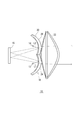
- FIG. 1 is a side view showing a schematic configuration of a lamp unit according to the first embodiment.
- FIG. 2 is a top view showing a schematic configuration of the lamp unit according to the first embodiment.
- the lighting unit 10 is provided on the optical path between the light sources 12 and 14, the spatial light modulator 16 that modulates the incident light, and the light source 12 and the spatial optical modulator 16, and the light L1 emitted from the light source 12.
- Is provided on the optical path between the first optical system 18 and the light source 14 and the space light modulator 16 so as to face the space light modulator 16, and the light L2 emitted from the light source 14 is the space light modulator.
- a second optical system 20 configured to face 16 and a projection lens 22 as a projection optical system are provided.
- the lamp unit 10 according to the present embodiment is used, for example, as a headlight for a vehicle.
- the spatial light modulator 16 includes, for example, a modulator such as a MEMS (Micro Electro Mechanical Systems) such as a DMD (Digital Mirror Device), a transmissive or reflective liquid crystal device, an optical device, an electro-optical device, or a magnetic optical device.
- a modulator such as a MEMS (Micro Electro Mechanical Systems) such as a DMD (Digital Mirror Device), a transmissive or reflective liquid crystal device, an optical device, an electro-optical device, or a magnetic optical device.
- the first optical system 18 includes a reflector 24, and the second optical system 20 includes a reflector 26.
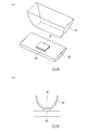
- FIG. 3A is an exploded perspective view of the light source
- FIG. 3B is a sectional view of a main part of the light source.
- the light source 12 (light source 14) according to the present embodiment, one semiconductor light emitting element 30 (blue light emitting element) is juxtaposed on the substrate 28. Further, a yellow phosphor 32 that is excited by blue light and emits yellow light is mounted on the upper surface of the semiconductor light emitting device 30. As a result, the light sources 12 and 14 can realize white light.
- the light source 12 further has a light collecting member 34 that collects the light emitted from the semiconductor light emitting element 30 and the yellow phosphor 32.
- a light collecting member 34 that collects the light emitted from the semiconductor light emitting element 30 and the yellow phosphor 32.
- the condensing member 34 for example, a compound parabolic concentrator is used.
- the semiconductor light emitting element 30 is an LED, an LD, an EL element, or the like.
- the reflector 24 is one optical element of the first optical system 18 configured so that the light emitted from the light source 12 is directed to the spatial light modulator 16.
- the reflector 26 is one optical element of the second optical system 20 configured such that the light emitted from the light source 14 is directed toward the spatial light modulator 16.
- the reflectors 24 and 26 are formed of curved surfaces having a flat surface.
- the light emitted from the light source 12 is reflected by the reflector 24, the light emitted from the light source 14 is reflected by the reflector 26, and at least a part of the reflected light is spatially light-modulated.
- the light is reflected again by the vessel 16 and the reflected light passes through the projection lens 22, so that the light source image is projected forward as a light distribution pattern.
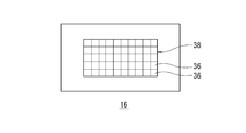
- FIG. 4 is a front view of the spatial light modulator.
- the spatial light modulator 16 according to the present embodiment is provided with a reflection region 38 in which a large number of reflection elements 36 composed of minute micromirrors are arranged in a matrix in the center, and the orientation of the reflection surface of the reflection element 36.
- Various light distribution patterns can be formed by individually controlling.
- the mirror surface of the reflecting element 36 changes in the vertical direction depending on whether it is on or off.
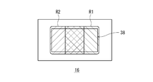
- FIG. 5 is a schematic diagram for explaining a range in which light emitted from a plurality of light sources according to the present embodiment irradiates a reflection region of a spatial light modulator.
- FIG. 6 is a diagram showing an example of a light distribution pattern formed by the lamp unit according to the present embodiment. Note that in FIG. 5, the reflection element 36 is not shown.
- the light emitted from the light source 12 irradiates the range R1 on the right side from the center of the reflection region 38, and the light emitted from the light source 14 is the reflection region 38. It is configured to irradiate the range R2 from the center to the left side. Further, in the lamp unit 10, the configuration and layout of each element are devised so that the range R1 and the range R2 partially overlap in the central portion of the reflection region 38. As a result, as shown in FIG. 6, the lamp unit 10 is formed by the light reflected in the reflection region 38 without increasing the applied current applied to the light source or using a light source having high brightness (high luminous flux). The central CV of the light distribution pattern PH can be brightened.
- FIG. 7A is a front view of the spatial light modulator in the case of forming another light distribution pattern that can be formed by the lamp according to the first embodiment
- FIG. 7B is the first embodiment. It is a figure which shows the other light distribution pattern which can be formed by the lamp
- the lamp unit 10 controls the spatial light modulator 16 and turns on the reflecting element 36 included in the range R3 in the reflecting region 38, so that only the light reflected in the range R3 faces the projection lens 22. , Form a light distribution pattern PH'forward. That is, in the lamp unit 10 according to the present embodiment, since the light other than the light emitted to the range R4 in the reflection region 38 contributes to the formation of the light distribution pattern PH', the utilization efficiency of the light of the light source is improved. Can be done. As a result, the power consumption is reduced and the thermal design in the lamp unit becomes easy.
- the light distribution pattern PH' when trying to form the light distribution pattern PH'with one light source that cannot be partially turned off, it is necessary to turn on the light source so as to constantly illuminate the entire reflection region 38. Moreover, not only the range R4 but also the light irradiating the range R5 on the right side of the reflection region 38 does not contribute to the formation of the light distribution pattern PH', so that the light utilization efficiency of the light source is low. That is, even when the same light distribution pattern PH'is formed, if one light source that cannot be partially turned off is used, the power required by the light source becomes large, which is compared with the lamp unit 10 according to the present embodiment. Therefore, it is inferior in terms of heat dissipation and power consumption.
- the lamp unit 10 is the light distribution pattern PH'that irradiates only a part of the maximum irradiation region (range R1 + range R2) that the lamp unit 10 can irradiate, or one of the maximum irradiation regions.
- a desired light distribution pattern is formed by turning off or dimming one of the first light source and the second light source, in addition to the modulation by the spatial light modulator 16. Can be obtained.
- Each of the light sources 12 and 14 according to the first embodiment includes one semiconductor light emitting element 30.
- the main feature of the lamp unit according to the second embodiment is that each of the two light sources includes a plurality of semiconductor light emitting elements.
- the other configuration of the lamp unit according to the second embodiment is the same as that of the first embodiment.
- FIG. 8 is a front view of each light source according to the second embodiment.
- three semiconductor light emitting elements 30a, 30b and 30c are mounted in a row on the substrate 28.
- a yellow phosphor 32 (not shown) is mounted on the upper surfaces (light emitting surfaces) of the three semiconductor light emitting elements 30a, 30b, and 30c.
- the yellow phosphor 32 may be divided into three like the light emitting surfaces of the three semiconductor light emitting elements 30a, 30b, and 30c, or may be a continuous plate-shaped member.
- the plurality of semiconductor light emitting elements 30a, 30b, and 30c are configured so that they can be turned on and off (brightness can be adjusted) for each group consisting of one or more semiconductor light emitting elements. As a result, various light distribution patterns can be formed. Further, in each light source, a plurality of semiconductor light emitting elements 30a, 30b, 30c are arranged in a line, and the amount of current applied to the semiconductor light emitting element 30b arranged in the center is a semiconductor arranged at the end. It is configured to be higher than the amount of current applied to the light emitting elements 30a and 30c. As a result, the central region of the light distribution pattern formed by the lamp unit can be brightly illuminated without increasing the amount of current of the entire light source. As a result, distant visibility can be improved.
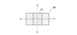
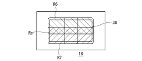
- FIG. 9 is a schematic diagram for explaining the range in which the light emitted from the plurality of light sources according to the second embodiment irradiates the reflection region of the spatial light modulator.
- FIG. 10 is a diagram showing an example of a light distribution pattern formed by the lamp unit according to the second embodiment. Note that in FIG. 9, the reflection element 36 is not shown.
- the light emitted from the first light source 40 irradiates the range R6 above the center of the reflection region 38 and is emitted from the second light source 42.
- the light is configured to illuminate the range R7 below the center of the reflection region 38.
- the light source 40 and the light source 42 irradiate the region including the horizontal line VV of the light distribution pattern PH with the light reflected in the range where the range R6 and the range R7 overlap or the light transmitted through the overlapping range. It is configured as follows.
- the region including the horizontal line of the light distribution pattern PH can be brightly illuminated without using a high-luminance (high luminous flux) light source, so that visibility at a distance can be improved.
- the lamp unit according to the second embodiment the range R6 and scope R7 is, each element of the structure and layout to overlap partially in the central portion R c of the reflective region 38 has been devised.
- the lamp unit according to the second embodiment does not increase the applied current applied to the light source or use a high-luminance (high luminous flux) light source, but in the reflection region 38.
- the central portion C H containing the line H-H of the light distribution pattern PH formed by the reflected light can be bright, thereby improving the distant visibility.
- the aspect ratio of the reflection region 38 (modulation region) in which a plurality of reflection elements 36 (modulation elements) are arranged in a matrix is smaller than the aspect ratio of the range R6 or the range R7. It is configured in. This facilitates the formation of a light distribution pattern suitable for the irradiation range (long rectangle in the left-right direction) in front of the vehicle.
- the lamp unit according to the third embodiment In the light sources 40 and 42 according to the second embodiment, three semiconductor light emitting elements 30a, 30b and 30c are arranged in a row.
- one semiconductor light emitting element 30b at the center of the light sources 40 and 42 in the second embodiment is divided into a plurality of semiconductor light emitting elements.
- the main feature is that the brightness can be adjusted individually for each semiconductor light emitting device.
- the other configuration of the lamp unit according to the third embodiment is the same as that of each of the above-described embodiments.
- FIG. 11 is a front view of each light source according to the third embodiment.
- six semiconductor light emitting elements 30a, 30d, 30e, 30f, 30g, and 30c are mounted side by side on the substrate 28.
- a yellow phosphor 32 (not shown) is mounted on the upper surface (light emitting surface) of each semiconductor light emitting element.
- the yellow phosphor 32 may be divided into six like the light emitting surfaces of the six semiconductor light emitting elements, or may be one continuous plate-shaped member.
- the plurality of semiconductor light emitting elements 30a, 30d, 30e, 30f, 30g, and 30c are configured so that they can be turned on and off (brightness can be adjusted) for each group consisting of one or more semiconductor light emitting elements. As a result, various light distribution patterns can be formed. Further, in each light source, a plurality of semiconductor light emitting elements 30a, 30d, 30e, 30c are arranged in a line, and the amount of current applied to the semiconductor light emitting elements 30d, 30e, 30f, 30g arranged in the center is determined. It is configured to be higher than the amount of current applied to the semiconductor light emitting elements 30a and 30c arranged at the ends. As a result, the central region of the light distribution pattern formed by the lamp unit can be brightly illuminated without increasing the amount of current of the entire light source. As a result, distant visibility can be improved.
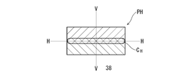
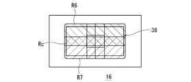
- FIG. 12 is a schematic diagram for explaining the range in which the light emitted from the plurality of light sources according to the third embodiment irradiates the reflection region of the spatial light modulator. Note that in FIG. 12, the reflection element 36 is not shown.
- the light emitted from the first light source 44 irradiates the range R6 above the center of the reflection region 38 and is emitted from the second light source 46.
- the light is configured to illuminate the range R7 below the center of the reflection region 38.
- the range R6 and scope R7 is, each element of the structure and layout to overlap partially in the central portion R c of the reflective region 38 has been devised.
- lamp unit according to the third embodiment as in the lamp unit according to the second embodiment, the light distribution pattern PH central portion C H containing the line H-H is shown in bright 10 Since it can be formed, distant visibility can be improved.
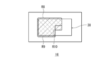
- FIG. 13 is a front view of the spatial light modulator in the case of forming another light distribution pattern that can be formed by the lamp according to the third embodiment.
- the semiconductor light emitting element 30c of the light source 44 is turned off and the semiconductor light emitting elements 30c and 30 g of the light source 46 are turned off, the range R8 from the center to the left side of the reflection region 38 is irradiated as shown in FIG.
- the lamp unit according to the third embodiment controls the spatial light modulator 16 and turns on the reflecting element 36 included in the range R9 in the reflection region 38, so that the light reflected in the range R9 is turned on. Only faces the projection lens 22 and forms a light distribution pattern PH'(see FIG. 7B) in front of it.
- the utilization efficiency of the light of the light source is enhanced. be able to. Further, since the range R10 is narrower than the range R4 shown in FIG. 7A, the light from the light source that does not contribute to the formation of the light distribution pattern PH'can be further reduced.
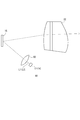
- FIG. 14 is a side view showing a schematic configuration of the lamp unit according to the fourth embodiment.
- the lighting unit according to each of the above-described embodiments includes a reflector that reflects the light of the light source as the first optical system and the second optical system, but the lighting unit 48 according to the present embodiment includes the light source 12.
- a condenser lens 50 is provided on the optical path between the space light modulator 16 and the light L1 emitted from the light source 12 is transmitted so as to be directed toward the space light modulator 16. Even the lamp unit 48 having such a configuration has the same function and effect as the lamp unit according to each of the above-described embodiments.
- One of the plurality of light sources may be configured such that the light distribution characteristic of the emitted light is different from the light distribution characteristic of the light emitted from the other of the plurality of light sources.
- the light irradiating the reflection region 38 has a non-uniform brightness distribution.
- various light distribution patterns can be formed as compared with the case where a plurality of light sources and semiconductor light emitting elements having the same light distribution characteristics are used.
- the lamp unit according to each of the above-described embodiments includes a plurality of light sources provided at remote locations, but the lamp unit does not necessarily have to include a plurality of light sources.
- the lighting unit according to the sixth embodiment is provided on the optical path between the light source 40, the spatial light modulator 16 that modulates the incident light, and the light source 40 and the spatial light modulator, and is a light source. It includes an optical system configured such that the light emitted from the 40 is directed toward the spatial light modulator 16.
- the light source 40 is a range in which the emitted light can irradiate the spatial light modulator 16 and includes a reflecting element 36 among a plurality of reflecting elements 36 included in the spatial light modulator 16 that does not contribute to the formation of a light distribution pattern.
- the range R5 in FIG. 7A is configured to reduce the irradiation of light.
- the lamp unit having such a configuration forms a light distribution pattern in which only a part of the maximum irradiation area that can be irradiated by the lamp unit is irradiated, or a light distribution pattern in which a part of the maximum irradiation area is darkly irradiated.
- it can be obtained not only by modulation by the spatial light modulator 16 but also by turning off or dimming a part of the light source 40. That is, the ADB (Adaptive Driving Beam) mode is realized by realizing the shape and brightness distribution of the light distribution pattern by combining not only the reflection control of each reflecting element 36 of the spatial light modulator 16 but also the lighting control of the light source.
- various light distribution patterns such as road surface drawing mode can be obtained while increasing the light utilization efficiency of the light source.
- the spatial light modulator is a reflection type
- the spatial light modulator may be a transmission type.
- the light source and each optical system are arranged on the opposite side of the projection member with the spatial light modulator in between.
- each semiconductor light emitting element may be capable of selectively realizing multi-valued brightness by controlling current or voltage as well as on / off binary brightness.
- the present invention has been described above with reference to the above-described embodiments, the present invention is not limited to the above-described embodiments, and the configurations of the embodiments are appropriately combined or substituted. Those are also included in the present invention. Further, it is also possible to appropriately rearrange the combinations and the order of processing in each embodiment based on the knowledge of those skilled in the art, and to add modifications such as various design changes to each embodiment, and such modifications. The embodiment to which is added may also be included in the scope of the present invention.
- the present invention can be used for a lamp unit for a vehicle.
Landscapes
- Engineering & Computer Science (AREA)
- General Engineering & Computer Science (AREA)
- Physics & Mathematics (AREA)
- Optics & Photonics (AREA)
- Microelectronics & Electronic Packaging (AREA)
- Non-Portable Lighting Devices Or Systems Thereof (AREA)
Priority Applications (1)
| Application Number | Priority Date | Filing Date | Title |
|---|---|---|---|
| JP2021527548A JPWO2020255703A1 (enExample) | 2019-06-18 | 2020-06-02 |
Applications Claiming Priority (2)
| Application Number | Priority Date | Filing Date | Title |
|---|---|---|---|
| JP2019112977 | 2019-06-18 | ||
| JP2019-112977 | 2019-06-18 |
Publications (1)
| Publication Number | Publication Date |
|---|---|
| WO2020255703A1 true WO2020255703A1 (ja) | 2020-12-24 |
Family
ID=73750085
Family Applications (1)
| Application Number | Title | Priority Date | Filing Date |
|---|---|---|---|
| PCT/JP2020/021834 Ceased WO2020255703A1 (ja) | 2019-06-18 | 2020-06-02 | 灯具ユニットおよび車両用前照灯 |
Country Status (3)
| Country | Link |
|---|---|
| JP (1) | JPWO2020255703A1 (enExample) |
| CN (1) | CN112097214A (enExample) |
| WO (1) | WO2020255703A1 (enExample) |
Families Citing this family (2)
| Publication number | Priority date | Publication date | Assignee | Title |
|---|---|---|---|---|
| KR102545227B1 (ko) * | 2021-07-06 | 2023-06-20 | 현대모비스 주식회사 | 차량용 램프 |
| CN115638382B (zh) * | 2022-04-02 | 2023-12-08 | 华为技术有限公司 | 一种光机模组、车灯模组和交通工具 |
Citations (5)
| Publication number | Priority date | Publication date | Assignee | Title |
|---|---|---|---|---|
| JP2017134918A (ja) * | 2016-01-25 | 2017-08-03 | スタンレー電気株式会社 | 車両用前照灯装置 |
| US20170284621A1 (en) * | 2016-03-31 | 2017-10-05 | Hyundai Motor Company | Lamp apparatus for vehicle |
| WO2018022700A1 (en) * | 2016-07-26 | 2018-02-01 | Texas Instruments Incorporated | Quasi-sparse optical illumination |
| JP2018092761A (ja) * | 2016-12-01 | 2018-06-14 | スタンレー電気株式会社 | 車両用灯具 |
| JP2019507950A (ja) * | 2016-02-24 | 2019-03-22 | ツェットカーヴェー グループ ゲーエムベーハー | 乗物用投光装置 |
Family Cites Families (3)
| Publication number | Priority date | Publication date | Assignee | Title |
|---|---|---|---|---|
| DE112013003050B4 (de) * | 2012-06-29 | 2023-06-22 | Koito Manufacturing Co., Ltd. | Fahrzeugleuchte und Verfahren zur Steuerung derselben |
| JP6869099B2 (ja) * | 2017-05-11 | 2021-05-12 | スタンレー電気株式会社 | ランプユニット、車両用灯具システム |
| JP6936646B2 (ja) * | 2017-07-14 | 2021-09-22 | スタンレー電気株式会社 | 車両用灯具 |
-
2020
- 2020-06-02 JP JP2021527548A patent/JPWO2020255703A1/ja active Pending
- 2020-06-02 WO PCT/JP2020/021834 patent/WO2020255703A1/ja not_active Ceased
- 2020-06-18 CN CN202010560877.1A patent/CN112097214A/zh active Pending
Patent Citations (5)
| Publication number | Priority date | Publication date | Assignee | Title |
|---|---|---|---|---|
| JP2017134918A (ja) * | 2016-01-25 | 2017-08-03 | スタンレー電気株式会社 | 車両用前照灯装置 |
| JP2019507950A (ja) * | 2016-02-24 | 2019-03-22 | ツェットカーヴェー グループ ゲーエムベーハー | 乗物用投光装置 |
| US20170284621A1 (en) * | 2016-03-31 | 2017-10-05 | Hyundai Motor Company | Lamp apparatus for vehicle |
| WO2018022700A1 (en) * | 2016-07-26 | 2018-02-01 | Texas Instruments Incorporated | Quasi-sparse optical illumination |
| JP2018092761A (ja) * | 2016-12-01 | 2018-06-14 | スタンレー電気株式会社 | 車両用灯具 |
Also Published As
| Publication number | Publication date |
|---|---|
| JPWO2020255703A1 (enExample) | 2020-12-24 |
| CN112097214A (zh) | 2020-12-18 |
Similar Documents
| Publication | Publication Date | Title |
|---|---|---|
| US10598330B2 (en) | Headlight for vehicles | |
| CN104279485B (zh) | 车辆用灯具 | |
| JP5815995B2 (ja) | 車両用灯具用の光学ユニット | |
| KR102622764B1 (ko) | 공간적으로 제어 가능한 반사기 요소를 갖는 조명 장치 | |
| US20180259156A1 (en) | Lighting system and a lighting method | |
| JP5252043B2 (ja) | 光源装置、光源ユニット及びプロジェクタ | |
| US20180259148A1 (en) | Light-beam-projecting device comprising a digital screen and headlamp equipped with such a device | |
| KR20190111798A (ko) | 자동차 헤드라이트용 조명 장치 | |
| WO2020255703A1 (ja) | 灯具ユニットおよび車両用前照灯 | |
| JP2012128997A (ja) | 車両用照明灯具 | |
| JP2007149552A (ja) | 照明装置 | |
| CN111505749B (zh) | 透镜阵列以及照明光学装置 | |
| JP2021192099A (ja) | プロジェクタ | |
| WO2021025028A1 (ja) | 車両用灯具 | |
| JP6695051B2 (ja) | 光源ユニット及び照明装置 | |
| US11454368B2 (en) | Lamp for vehicle and vehicle including same | |
| JP4826296B2 (ja) | 光源装置、光源ユニット及びプロジェクタ | |
| JP2017199558A (ja) | 光源ユニット、車両用照明装置、及び投射型映像表示装置 | |
| JP2021039866A (ja) | 灯具ユニット | |
| JP2020057511A (ja) | 車両用灯具 | |
| CN210801005U (zh) | 车辆用灯具 | |
| JP2021144786A (ja) | 灯具ユニット | |
| US11852307B1 (en) | Headlight | |
| TW201533389A (zh) | 可投射出重疊熱點的車燈結構 | |
| WO2019218644A1 (zh) | 光源装置及汽车前照灯 |
Legal Events
| Date | Code | Title | Description |
|---|---|---|---|
| 121 | Ep: the epo has been informed by wipo that ep was designated in this application |
Ref document number: 20826274 Country of ref document: EP Kind code of ref document: A1 |
|
| ENP | Entry into the national phase |
Ref document number: 2021527548 Country of ref document: JP Kind code of ref document: A |
|
| NENP | Non-entry into the national phase |
Ref country code: DE |
|
| 122 | Ep: pct application non-entry in european phase |
Ref document number: 20826274 Country of ref document: EP Kind code of ref document: A1 |