WO2020250656A1 - 端子 - Google Patents
端子 Download PDFInfo
- Publication number
- WO2020250656A1 WO2020250656A1 PCT/JP2020/020577 JP2020020577W WO2020250656A1 WO 2020250656 A1 WO2020250656 A1 WO 2020250656A1 JP 2020020577 W JP2020020577 W JP 2020020577W WO 2020250656 A1 WO2020250656 A1 WO 2020250656A1
- Authority
- WO
- WIPO (PCT)
- Prior art keywords
- slide member
- terminal
- electric wire
- connecting piece
- contact
- Prior art date
- Legal status (The legal status is an assumption and is not a legal conclusion. Google has not performed a legal analysis and makes no representation as to the accuracy of the status listed.)
- Ceased
Links
Images










Classifications
-
- H—ELECTRICITY
- H01—ELECTRIC ELEMENTS
- H01R—ELECTRICALLY-CONDUCTIVE CONNECTIONS; STRUCTURAL ASSOCIATIONS OF A PLURALITY OF MUTUALLY-INSULATED ELECTRICAL CONNECTING ELEMENTS; COUPLING DEVICES; CURRENT COLLECTORS
- H01R13/00—Details of coupling devices of the kinds covered by groups H01R12/70 or H01R24/00 - H01R33/00
- H01R13/02—Contact members
- H01R13/26—Pin or blade contacts for sliding co-operation on one side only
-
- H—ELECTRICITY
- H01—ELECTRIC ELEMENTS
- H01R—ELECTRICALLY-CONDUCTIVE CONNECTIONS; STRUCTURAL ASSOCIATIONS OF A PLURALITY OF MUTUALLY-INSULATED ELECTRICAL CONNECTING ELEMENTS; COUPLING DEVICES; CURRENT COLLECTORS
- H01R4/00—Electrically-conductive connections between two or more conductive members in direct contact, i.e. touching one another; Means for effecting or maintaining such contact; Electrically-conductive connections having two or more spaced connecting locations for conductors and using contact members penetrating insulation
- H01R4/28—Clamped connections, spring connections
- H01R4/50—Clamped connections, spring connections utilising a cam, wedge, cone or ball also combined with a screw
- H01R4/5075—Clamped connections, spring connections utilising a cam, wedge, cone or ball also combined with a screw having an uneven wire receiving surface to improve the contact
-
- H—ELECTRICITY
- H01—ELECTRIC ELEMENTS
- H01R—ELECTRICALLY-CONDUCTIVE CONNECTIONS; STRUCTURAL ASSOCIATIONS OF A PLURALITY OF MUTUALLY-INSULATED ELECTRICAL CONNECTING ELEMENTS; COUPLING DEVICES; CURRENT COLLECTORS
- H01R13/00—Details of coupling devices of the kinds covered by groups H01R12/70 or H01R24/00 - H01R33/00
- H01R13/46—Bases; Cases
- H01R13/514—Bases; Cases composed as a modular blocks or assembly, i.e. composed of co-operating parts provided with contact members or holding contact members between them
-
- H—ELECTRICITY
- H01—ELECTRIC ELEMENTS
- H01R—ELECTRICALLY-CONDUCTIVE CONNECTIONS; STRUCTURAL ASSOCIATIONS OF A PLURALITY OF MUTUALLY-INSULATED ELECTRICAL CONNECTING ELEMENTS; COUPLING DEVICES; CURRENT COLLECTORS
- H01R4/00—Electrically-conductive connections between two or more conductive members in direct contact, i.e. touching one another; Means for effecting or maintaining such contact; Electrically-conductive connections having two or more spaced connecting locations for conductors and using contact members penetrating insulation
- H01R4/28—Clamped connections, spring connections
- H01R4/48—Clamped connections, spring connections utilising a spring, clip, or other resilient member
- H01R4/489—Clamped connections, spring connections utilising a spring, clip, or other resilient member spring force increased by screw, cam, wedge, or other fastening means
-
- H—ELECTRICITY
- H01—ELECTRIC ELEMENTS
- H01R—ELECTRICALLY-CONDUCTIVE CONNECTIONS; STRUCTURAL ASSOCIATIONS OF A PLURALITY OF MUTUALLY-INSULATED ELECTRICAL CONNECTING ELEMENTS; COUPLING DEVICES; CURRENT COLLECTORS
- H01R2107/00—Four or more poles
Definitions
- the technology disclosed in this specification relates to terminals.
- an electric wire with a terminal in which a terminal is connected to a core wire exposed from the terminal of the electric wire is known.
- a terminal for example, there is a terminal provided with a crimping portion for crimping from the outside to a core wire exposed from the end of the electric wire.
- a terminal having a predetermined shape is formed by pressing a metal plate material.
- the terminals are mounted on the mounting portion of the lower mold located on the lower side of the pair of molds that can move relative to each other in the vertical direction.
- the core wire exposed from the terminal of the electric wire is placed on the crimping portion of the terminal.
- one or both of the pair of dies are moved in a direction approaching each other, and the crimping portion is sandwiched between the crimping portion of the upper die and the mounting portion of the lower die to plastically deform the crimping portion. And crimp it to the core of the wire.
- the terminal is connected to the terminal of the electric wire (see Patent Document 1).
- the technique disclosed in the present specification has been completed based on the above circumstances, and is a technique capable of connecting a terminal and an electric wire without using a relatively large-scale jig.
- the purpose is to provide.
- the terminal according to the present disclosure is a terminal in which an electric wire can be inserted in a predetermined direction, has a contact surface that can contact the electric wire, and has a connecting piece portion that can be deformed in a direction intersecting the insertion direction of the electric wire. It forms a tubular shape that can be moved from a separated position that is a position away from the main body and the terminal main body to an overlapping position that is a position that overlaps the outside of the terminal main body while being in contact with the terminal main body from the tip side of the connection piece.
- the slide member has a slide member, and the slide member is provided with a pressurizing portion that projects inward and pressurizes the connecting piece portion so as to come into contact with the electric wire, and the slide member is provided with the pressurizing portion.
- a wide portion having an inner shape of the slide member wider than the narrow portion is provided, and the narrow portion overlaps the outside of the connecting piece portion at the overlapping position, so that the pressurizing portion is formed.
- the connecting piece is pressed, and the slide member is pressed from the wide portion in the pressurizing direction as the tip of the wall portion constituting the wide portion toward the tip of the insertion direction of the electric wire.
- a guide slope that spreads out is formed.
- the terminal and the electric wire can be connected without using a relatively large-scale jig, and the slide member can be stably assembled to the terminal body in advance. Can be done.
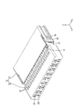
- FIG. 1 is a perspective view showing a connector according to the present embodiment.
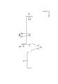
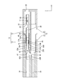
- FIG. 2 is a cross-sectional view showing a connector.
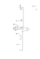
- FIG. 3 is a perspective view showing a female terminal when the slide member and the terminal body are in the first state.
- FIG. 4 is a side view showing a female terminal when the slide member and the terminal body are in the first state.
- FIG. 5 is a partially broken plan view showing a female terminal when the slide member and the terminal body are in the first state.
- FIG. 6 is a perspective view showing a female terminal when the slide member and the terminal body are in the first state.
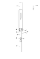
- FIG. 7 is a side view showing a female terminal when the slide member and the terminal body are in the second state.
- FIG. 8 is a perspective view showing the terminal body.
- FIG. 9 is a side view showing the terminal body.
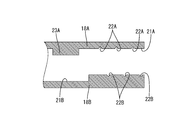
- FIG. 10 is a partially enlarged cross-sectional view showing serrations.
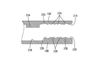
- FIG. 11 is a partially enlarged cross-sectional view showing variations in serrations.
- FIG. 12 is a partially enlarged cross-sectional view showing variations in serrations.
- FIG. 13 is a rear view showing the terminal body.
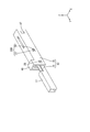
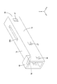
- FIG. 14 is a perspective view showing a slide member.
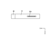
- FIG. 15 is a top view showing the slide member.
- FIG. 16 is a side view showing the slide member.
- FIG. 17 is a front view showing a slide member.
- FIG. 18 is a front view showing a slide member in which the protruding height of the contact portion is changed.
- FIG. 19 is a perspective view showing the connector housing.
- FIG. 20 is a perspective view showing a state in which the female terminal is attached to the connector housing.
- FIG. 21 is a cross-sectional view showing a state in which the female terminal is attached to the connector housing.
- FIG. 22 is a perspective view showing a state in which the rear holder is attached to the connector housing at the temporarily locked position.
- FIG. 23 is a cross-sectional view showing a state in which the rear holder is attached to the connector housing at the temporarily locked position.
- FIG. 24 is a perspective view showing a state in which the electric wire is inserted.
- FIG. 25 is a cross-sectional view showing a state in which an electric wire is inserted.
- FIG. 26 is a cross-sectional view showing a state in which the slide member is in the process of transitioning from the first state to the second state.
- the terminal according to the present disclosure is a connection piece portion capable of inserting an electric wire in a predetermined direction, having a contact surface that can contact the electric wire, and being deformable in a direction intersecting the insertion direction of the electric wire.
- a cylinder that can be moved from a separated position that is a position away from the terminal body to an overlapping position that is a position that overlaps the outside of the terminal body while being in contact with the terminal body from the tip side of the connection piece.
- the slide member has a shape-like slide member, and the slide member is provided with a pressurizing portion that projects inward and pressurizes the connection piece portion so as to come into contact with the electric wire.
- a wide portion having an inner shape of the slide member wider than the narrow portion is provided on the side in the pressurizing direction, and the narrow portion overlaps the outside of the connecting piece portion at the overlapping position.
- the pressing portion presses the connecting piece portion, and the sliding member has the pressure portion in the pressurizing direction as the tip of the wall portion constituting the wide portion toward the tip of the insertion direction of the electric wire.
- a guide slope portion that is wider than the wide portion is formed.
- the connecting piece can be pressed against the electric wire by moving the slide member along the insertion direction of the electric wire.
- the connection piece and the electric wire are electrically connected, the electric wire and the terminal can be electrically connected without using a relatively large-scale jig.
- the guide slope portion guides the slide member, so that both can be stably assembled.
- the connecting piece portions are formed in pairs so that the contact surfaces face each other, and at least one of the paired connecting piece portions slides in contact with the guide slope portion of the slide member. It is preferable to be guided inside.
- At least one connecting piece is guided to the inside of the tubular slide member by sliding contact with the guide slope.
- the slide member is in a first state in which the wide portion overlaps the outside of the terminal body and the narrow portion does not overlap the outside of the connection piece on one or the other of the terminal body and the slide member.
- the first state locking mechanism for holding the above and the narrow portion overlap the outside of the connection piece portion, and the pressurizing portion presses the connection piece portion to bring the connection piece portion into contact with the electric wire. It is preferable that the second state locking and subsequent states for holding the slide member are provided in the state.
- the slide member preferably has a covering portion that covers the guide slope portion.
- the slide member is provided with a jig contact portion that allows the slide member to move along the insertion direction by contacting the slide member from the outside.
- the jig contact portion also serves as a covering portion that covers the guide slope portion.
- the terminal can be miniaturized as compared with the case where the jig contact portion and the cover portion are provided separately.
- An invitation slope portion that guides the tip of the electric wire inserted into the terminal body to a required posture by increasing the amount of protrusion toward the pressurizing portion side at the end portion of the slide member opposite to the wide portion. It is preferable to have a configuration having.
- the electric wire is sandwiched between the connecting pieces in a posture bent in the insertion direction at a position different from the contact surface.
- a holding protrusion may be provided.
- the holding force is received by the holding protrusion to increase the holding force of the electric wire.
- the contact surface is formed with serrations that bite into the surface of the electric wire while the connecting piece is pressed against the electric wire.
- the serration bites into the surface of the electric wire, so that the holding force between the electric wire and the terminal is improved. Further, since the insulating film formed on the surface of the electric wire can be peeled off by serration, the electric resistance value between the terminal and the electric wire can be reduced.
- the serrations are preferably formed in a groove shape extending in a direction orthogonal to the insertion direction, and are preferably formed side by side at intervals in the insertion direction.
- the electric wire can be held by serrations at a plurality of locations in the insertion direction of the electric wire, so that the holding force between the electric wire and the terminal can be improved. Further, since the electric wire and the terminal can be electrically connected by serrations at a plurality of places in the insertion direction of the electric wire, the electric resistance value between the terminal and the electric wire can be reduced.
- the contact surface is formed with an electric wire guide recess extending along the insertion direction.
- the electric wire can be easily arranged on the contact surface by attaching the electric wire to the electric wire guide groove.
- the terminal body has a terminal window portion that can detect that the end edge of the electric wire is arranged at a predetermined position when the electric wire is arranged on the connection piece.
- the electric wire with a terminal according to the present disclosure includes the terminal described in any one of (1) to (13) above and the electric wire connected to the terminal.
- the connector according to the present disclosure is a connector including a connector housing having a cavity for accommodating terminals and a rear holder attached to the rear end of the connector housing in the insertion direction of the terminals accommodated in the cavity.
- the rear holder is provided with an insertion hole that communicates with the cavity.
- the terminal can be held in the connector housing in a retaining state by the rear holder.
- the rear holder is movable along the insertion direction, and when the rear holder moves from the rear to the front in the insertion direction, the rear holder comes into contact with the slide member from the rear in the insertion direction and the slide member is moved forward in the insertion direction. It is preferable to have a structure having a slide member pressing portion that moves the slide member from the first state to the second state by pressing.
- the slide member can be pressed by the slide member pressing portion of the rear holder by moving the rear holder.
- the rear holder can be moved and at the same time, the electric wire and the terminal can be electrically connected.
- the terminal main body is opened with a terminal window portion capable of detecting that the end edge of the electric wire is arranged at a predetermined position in a state where the electric wire is arranged on the connection piece portion. It is preferable that the connector housing is provided with a connector window portion that communicates the terminal window portion of the terminal with the outside.
- the connector 10 accommodates a female terminal 12 (an example of a terminal) connected to the terminal of the electric wire 11.
- the electric wire 60 with a terminal according to the present embodiment includes a female terminal 12 and an electric wire 11 connected to the female terminal 12.
- the Z direction shown in the drawings will be upward, the Y direction will be forward, and the X direction will be left.
- only some of the members may be coded, and the codes of other members may be omitted.
- the electric wire 11 is formed by surrounding the outer peripheral surface of the core wire 13 with an insulating coating 14 made of an insulating synthetic resin.
- the insulating coating 14 is peeled off from the terminal portion of the electric wire 11, and the core wire 13 is exposed.
- the core wire 13 according to the present embodiment is a so-called single core wire made of one metal wire.
- the core wire 13 may be a stranded wire formed by twisting a plurality of fine metal wires.
- any metal such as copper, copper alloy, aluminum, and aluminum alloy can be appropriately selected as needed.
- the core wire 13 according to this embodiment is made of copper or a copper alloy.
- the female terminal 12 includes a metal terminal body 15 and a slide member 16 that can slide and move relative to the terminal body 15.
- the terminal body 15 and the slide member 16 according to the present embodiment are formed by forming a metal plate material into a required shape by shearing and bending by a press.
- any metal such as aluminum, aluminum alloy, and stainless steel can be appropriately selected as needed.
- the terminal body 15 according to this embodiment is not particularly limited, but is made of copper or a copper alloy.
- a plating layer may be formed on the surface of the terminal body 15.
- any metal such as tin, nickel, and silver can be appropriately selected as required.
- the terminal body 15 according to this embodiment is tin-plated.
- the terminal body 15 and the slide member 16 may be formed into a required shape by welding or cutting metal as well as by pressing, and the slide member 16 is not necessarily made of metal but is made of resin. You may.
- the terminal body 15 is composed of a connection cylinder portion 17 into which a male terminal (not shown) on the other side is inserted and a connection piece portion extending rearward from the connection cylinder portion 17.
- a certain upper connecting piece 18A and a lower connecting piece 18B are provided.
- the connecting cylinder portion 17 has a square tubular shape extending in the front-rear direction. The front end of the connecting cylinder 17 is opened so that a male terminal on the other side can be inserted.
- an elastic connecting piece portion 19 extending forward from the rear portion of the connecting cylinder portion 17 and elastically deformable is arranged inside the connecting cylinder portion 17.
- the male terminal inserted into the connecting cylinder portion 17 is in contact with the elastic connecting piece portion 19.
- a square tubular base portion 20 is provided behind the connecting tubular portion 17.
- An upper connecting piece 18A (an example of a connecting piece) is provided at the rear end of the upper wall of the base 20 so as to extend rearward
- a lower connecting piece 18B is provided at the rear end of the lower wall of the base 20.
- An example of a connection piece is provided so as to extend rearward.
- the upper connecting piece 18A and the lower connecting piece 18B have an elongated shape extending in the front-rear direction, and are located between the upper connecting piece 18A and the lower connecting piece 18B from the front end side to the rear end side. That is, the electric wire 11 can be inserted into the base 20 in the Y direction (the insertion direction of the electric wire).
- the upper connecting piece 18A and the lower connecting piece 18B have substantially the same length dimension in the front-rear direction.
- the upper connecting piece 18A is formed so that the tip portion can be deformed in the vertical direction with the rear end portion of the base portion 20 as a fulcrum.
- the lower surface of the upper connecting piece 18A is a contact surface 21A that comes into contact with the core wire 13.
- a plurality of serrations 22A extending in the direction orthogonal to the insertion direction, that is, in the left-right direction and forming a groove shape, are spaced apart in the front-rear direction. It is formed in parallel.
- the contact surface 21A of the upper connecting piece portion 18A is provided with an upper holding protrusion 23A that projects downward. Serrations 22A may also be formed on the lower surface of the upper holding protrusion 23A.
- the lower connecting piece 18B is formed so that the tip portion can be deformed in the vertical direction with the rear end portion of the base portion 20 as a fulcrum.
- the upper surface of the lower connecting piece 18B is a contact surface 21B that contacts the core wire 13, and similarly to the contact surface 21A of the upper connecting piece 18A, a plurality of groove-shaped serrations 22B are parallel to each other at intervals in the front-rear direction. Is formed in.
- the serrations 22A and 22B are formed at positions where they are out of phase in the front-rear direction and do not overlap each other (see FIG. 10).
- a lower holding protrusion 23B that projects upward is formed on the contact surface 21B of the lower connecting piece 18B.
- the upper holding protrusion 23A and the lower holding protrusion 23B are formed at positions shifted in the front-rear direction.
- the upper holding protrusion 23A is provided on the front side and the lower holding protrusion 23B is provided on the rear side.
- the positions of the steps in the front-rear direction of the lower holding protrusion 23B and the upper holding protrusion 23A are deviated from each other, and are separated by a dimension slightly larger than the diameter of the core wire 13 of the electric wire 11. ..
- the central portion of the contact surface 21B of the lower connecting piece portion 18B in the left-right direction is depressed in an inclined shape, and the electric wire guide recess 48 extending along the insertion direction of the electric wire 11 is formed. It is formed.
- the core wire 13 and the terminal body 15 are electrically connected by contacting the metal surface with the contact surface 21A of the upper connecting piece 18A and the contact surface 21A of the lower connecting piece 18B.
- the shapes of the serrations 22A and the serrations 22B can be appropriately selected as needed.
- the serrations 22A and 22B have a so-called V-shaped groove shape having a V-shaped cross section.
- the serrations 22A and 22B may be formed in a curved surface shape that gently undulates in the front-rear direction.
- the rear wall may be formed so as to be steep, and the front wall may have an inclined surface that expands toward the rear. In this case, the rear walls of the serrations 22A and 22B bite into the surface of the core wire 13, so that the holding force between the electric wire 11 and the female terminal 12 can be improved.
- the shapes of serrations 22A and 22B can be any shape other than the above.
- it may be a so-called U-shaped groove, or the bottom wall and both side walls of the groove-shaped serrations 22A and 22B may be orthogonal to each other.
- the terminal body 15 is provided with a terminal window portion 24 that opens upward at a position behind the connection cylinder portion 17 and in front of the base portion 20. From the terminal window portion 24, the electric wire 11 is inserted into the vicinity of the terminal window portion 24 at a predetermined position, that is, through the space between the upper connecting piece portion 18A and the lower connecting piece portion 18B, and the core wire 13
- the front end of the can be detected from the outside. Detectable from the outside includes that it can be visually confirmed by an operator from the outside, and also includes that it can be detected by a camera (not shown) from the outside, and a probe (not shown) from the outside. ) Is inserted to electrically detect the front end portion of the core wire 13.
- the slide member 16 has a square tubular shape extending in the front-rear direction.
- the slide member 16 is formed by a known method such as cutting, casting, or pressing, if necessary.
- any metal such as copper, copper alloy, aluminum, aluminum alloy, and stainless steel can be appropriately selected as needed.
- the slide member 16 according to the present embodiment is formed by pressing a stainless steel plate material.
- a plating layer may be formed on the surface of the slide member 16.
- any metal such as tin, nickel, and silver can be appropriately selected as required.
- the cross section of the inner shape of the slide member 16 on the surface orthogonal to the Y direction is the same as or slightly the same as the cross section of the outer shape of the region of the terminal body 15 where the upper connecting piece 18A and the lower connecting piece 18B are provided. It is formed large.
- the slide member 16 has a square tubular shape capable of surrounding the pair of connecting pieces 18A and the lower connecting piece 18B of the terminal body 15 from the outside.
- An upper pressurizing portion 25A protruding downward as a pressurizing portion is provided on a portion of the upper wall 70 of the slide member 16 closer to the rear.
- the lower wall of the slide member 16 is provided with a lower pressurizing portion 25B projecting upward at a position facing the upper pressurizing portion 25A.
- the portion where the upper pressurizing portion 25A and the lower pressurizing portion 25B are provided is a narrow portion 16B in which the inner dimension of the slide member 16 in the vertical direction is narrower than that of the front portion.
- the cross-sectional shape of the portion in front of the portion where the upper pressurizing portion 25A and the lower pressurizing portion 25B are provided is provided by the upper connecting piece portion 18A and the lower connecting piece portion 18B of the terminal body 15. Since it is formed to be the same as or slightly larger than the cross-sectional shape of the formed region, the portion can be set at a position where it overlaps the outside of the rear end portion of the terminal body 15, that is, a position where it fits outside, and the upper side is added at that position.
- the pressing portion 25A and the lower pressing portion 25B do not come into contact with the upper connecting piece portion 18A and the lower connecting piece portion 18B, and do not deform these connecting pieces 18A and 18B inward (see FIG. 21).
- the front portion of the upper pressurizing portion 25A and the lower pressurizing portion 25B of the slide member 16 is hereinafter referred to as a wide portion 16A.
- the upper connecting piece 18A and the lower connecting piece 18B are not deformed, and in this state, the upper connecting piece 18A and Since the distance between the lower connecting piece 18B and the core wire 13 is set to be larger than the diameter of the core wire 13, the electric wire 11 can be freely inserted into the terminal body 15.
- Temporary locking receiving portions 26 are opened on the left and right side walls of the slide member 16 at a position closer to the front end portion in the front-rear direction, and the main locking receiving portion 27 is opened at a position behind the temporary locking receiving portion 26. Has been done.
- the temporary locking receiving portion 26 and the main locking receiving portion 27 can be elastically locked with the locking projections 28 provided on the left and right side walls of the terminal body 15.
- the upper pressurizing portion 25A and the lower pressurizing portion 25B of the slide member 16 are on the upper side of the terminal body 15. It is separated rearward from the rear end edge of the connecting piece 18A and the lower connecting piece 18B, and these connecting pieces 18A and 18B are not deformed.
- This state is referred to as a first state in the present specification, and a locking mechanism including a temporary locking receiving portion 26 of the slide member 16 and a locking projection 28 is referred to as a first state locking mechanism 26A (see FIG. 4).
- the locking projection 28 of the terminal body 15 comes out of the temporary locking receiving portion 26 of the slide member 16 and is locked to the main locking receiving portion 27 in front. It will be in a state of being.
- the upper pressurizing portion 25A and the lower pressurizing portion 25B of the slide member 16 are in a state of riding on the center of the upper connecting piece portion 18A and the lower connecting piece portion 18B of the terminal body 15, and as a result, these 18A and 18B are deformed so as to be pressed against the electric wire 11 (see FIG. 2).
- This state is referred to as a second state in the present specification, and a locking mechanism including the main locking receiving portion 27 of the slide member 16 and the locking projection 28 is referred to as a second state locking mechanism 26B (see FIG. 6).
- FIGS. 17 and 18 when the terminal body 15 having the same shape is used by appropriately changing the height dimension of the upper pressurizing portion 25A and the height dimension of the lower pressurizing portion 25B. Even so, the electric wires 11 having different diameters of the core wires 13 can be connected to the female terminals 12.
- FIG. 18 shows a case where the height dimension of the upper pressurizing portion 25A and the height dimension of the lower pressurizing portion 25B are lower than those shown in FIG. In this way, the electric wire 11 having a core wire 13 having a diameter larger than that shown in FIG. 17 can be connected to the female terminal 12 by using the terminal body 15 having the same shape.
- the upper holding protrusion 23A of the upper connecting piece 18A presses the core wire 13 from above.
- the electric wire 11 has a recess that can receive the upper holding protrusion 23A by being depressed in a stepped shape in front of the lower holding protrusion 23B.
- the core wire 13 and the female terminal 12 are also electrically connected by the upper holding protrusion 23A. In this way, the electric wire 60 with terminals can be obtained.
- a jig contact portion 46 (an example of a covering portion) projecting upward from the upper wall 70 is provided at the front end portion of the slide member 16.
- This is a cover shape that has a square gate shape and a hollow inside.
- the jig 45 comes into contact with the jig contact portion 46 from the rear, and the slide member 16 can be moved forward by pushing the slide member 16 forward by the jig 45 (see FIG. 26).
- the jig 45 has an elongated plate shape or a rod shape.
- the jig 45 is made of a known material such as metal or synthetic resin.
- the jig 45 is relatively small in size as compared with a mold and equipment for operating the mold. Therefore, the increase in cost caused by the jig 45 is suppressed.
- a pair of invitation portions 47 projecting inward of the slide member 16 are provided on the left and right side walls.
- the invitation portion 47 is formed narrower from the rear to the front.
- a guide slope portion 50 is formed directly below the jig contact portion 46 of the slide member 16. As a result, the guide slope portion 50 is covered with the jig contact portion 46.
- the guide slope portion 50 is formed in a tongue piece shape in which the tip side is inclined toward the tip side toward the upper end connecting piece portion 18A at a position facing the upper connecting piece portion 18A of the terminal body 15, that is, the tip is inclined upward. In the form, it is integrally manufactured with the same material as the plate material constituting the terminal body 15.
- the guide slope portion 50 is formed so as to expand upward from the front end portion of the upper wall 70 constituting the wide portion 16A toward the front.
- the guide slope portion 50 is formed so as to be wider than the wide portion 16A in the vertical direction in which the upper pressurizing portion 25A and the lower pressurizing portion 25B press the core wire 13 of the electric wire 11.
- the length dimension of the guide slope portion 50 is set so as not to protrude from the jig contact portion 46 and is hidden in the jig contact portion 46. Therefore, when the slide member 16 is handled alone, the guide slope portion 50 is hidden. It is prevented that 50 interferes with other parts and the like.
- the connector 10 includes a connector housing 30 having a plurality of cavities 29 accommodating female terminals 12 and a rear holder 31 assembled to a rear end portion of the connector housing 30.
- the connector housing 30 has a substantially rectangular parallelepiped shape that is flat in the vertical direction and extends in the horizontal direction.
- the connector housing 30 is formed by injection molding an insulating synthetic resin.
- a plurality of cavities 29 extending in the front-rear direction for accommodating the female terminal 12 are arranged in parallel at intervals in the left-right direction, and are vertically stacked in two stages.
- the cavities 29 formed in the upper stage and the cavities 29 formed in the lower stage are arranged at positions shifted vertically.
- the number of cavities 29 is arbitrary, and the number of stages when they are stacked vertically is also arbitrary.
- the front end of the cavity 29 is open forward so that a male terminal can be inserted.
- the rear end of the cavity 29 is open to the rear so that the female terminal 12 can be accommodated from the rear.
- a connector window 33 penetrating the wall constituting the cavity 29 is formed at a position corresponding to the terminal window 24 of the female terminal 12.
- the connector window portion 33 allows the terminal window portion 24 to communicate with the outside. From the connector window portion 33, the terminal window portion 24 of the female terminal 12 can be detected from the outside. As a result, the front end portion of the core wire 13 can be detected from the outside through the connector window portion 33 and the terminal window portion 24.
- the connector housing 30 has a partition wall 34 that partitions the cavity 29 formed in the upper stage and the cavity 29 formed in the lower stage.
- the partition wall 34 extends rearward from the rear end of the cavity 29.
- partition walls 35 extending in the front-rear direction and protruding vertically are provided, respectively.
- the partition wall 35 electrically insulates the female terminals 12 housed in each cavity 29 from the female terminals 12 adjacent to each other in the left-right direction.
- Temporary locking locks 36 projecting outward are provided at positions near the rear ends of the left and right side walls of the connector housing 30, and the temporary locking locks 36 are located in front of the temporary locking locks 36.
- the locking lock portion 37 is provided so as to project outward.
- the rear holder 31 has a box shape that opens forward.
- the rear holder 31 is formed by injection molding an insulating synthetic resin.
- the rear holder 31 is fitted onto the latter half of the connector housing 30.
- Temporary locking lock portions 36 of the connector housing 30 and lock receiving portions 38 that can be elastically locked to the main locking lock portions 37 are provided at positions near the front ends of the left and right side walls of the rear holder 31. ..
- the lock receiving portion 38 has a substantially gate shape.
- the temporary locking lock portion 36 of the connector housing 30 and the lock receiving portion 38 of the rear holder 31 are locked, so that the rear holder 31 is held at the temporary locking position with respect to the connector housing 30. Further, the rear holder 31 is held at the main locking position with respect to the connector housing 30 by locking the main locking lock portion 37 of the connector housing 30 and the lock receiving portion 38 of the rear holder 31.
- the rear holder 31 is provided with a plurality of insertion holes 39 through which the electric wires 11 are inserted, which are arranged in parallel in the left-right direction and arranged in two stages vertically.
- the insertion hole 39 is provided at a position corresponding to the cavity 29 of the connector housing 30.
- the inner diameter of the insertion hole 39 is set to be the same as or slightly larger than the outer diameter of the insulating coating 14 of the electric wire 11.
- the hood portion 41 into which the connector housing 30 is fitted is opened forward in the rear holder 31.
- a pair of protruding walls 42A and 42B are provided near the center in the vertical direction so as to project forward into the hood 41 and are arranged at intervals in the vertical direction.
- the vertical distance between the pair of protruding walls 42A and 42B is set to be the same as or slightly larger than the vertical thickness dimension of the partition wall 34 of the connector housing 30.
- the pair of protruding walls 42A and 42B of the rear holder 31 are located behind the rear end edge of the partition wall 34 of the connector housing 30. ..
- the partition wall 34 of the connector housing 30 is fitted between the pair of protruding walls 42A and 42B of the rear holder 31. As a result, the rear holder 31 is prevented from being displaced in the vertical direction with respect to the connector housing 30.
- the inner wall of the hood portion 41 has a region slightly rearward from the front end edge formed thinner than the other regions. As a result, a step is formed on the inner wall of the hood portion 41 between the position near the front end portion and the rear portion.
- This step is a slide member pressing portion 43 that comes into contact with the rear end portion 44 of the slide member 16 from the rear when the rear holder 31 moves from the temporary locking position to the main locking position with respect to the connector housing 30.
- the slide member pressing portion 43 abuts on the rear end portion 44 of the slide member 16 from the rear and presses the slide member 16 in the first state forward so that the slide member 16 moves to the second state. It has become.
- the terminal body 15 and the slide member 16 are formed by a known method.
- the slide member 16 is assembled to the terminal body 15 from the rear in a posture in which the wide portion 16A is facing away. Since the vertical inner dimension of the wide portion 16A is formed to be the same as or slightly larger than the dimension between the upper surface of the upper connecting piece 18A of the terminal body 15 and the lower surface of the lower connecting piece 18B, the terminal body 15 Can be inserted into the wide portion 16A until the tips of the upper connecting piece 18A and the lower connecting piece 18B abut on the front edges of the upper pressurizing portion 25A and the lower pressurizing portion 25B (FIG. 21).
- the tip of the upper connecting piece 18A is the terminal below the jig contact portion 46. It may hit the main body 15.
- the guide slope portion 50 is provided on the terminal body 15 in the present embodiment, the upper connecting piece portion 18A slides along the slope so that the guide slope portion 18A is smoothly guided into the wide portion 16A. That is, the slide member 16 is guided so as to ride on the outside of the upper connecting piece portion 18A.
- the terminal body 15 is engaged.
- the front end edge of the slide member 16 comes into contact with the stop projection 28 from the rear, and the side wall of the slide member 16 is expanded and deformed.
- the slide member 16 is further pushed forward, the side wall of the slide member 16 is restored and deformed, and the temporary locking receiving portion 26 of the slide member 16 is locked to the locking projection 28 of the terminal body 15.
- the slide member 16 is held in the first state with respect to the terminal body 15.
- the female terminal 12 is obtained (see FIG. 3).
- the connector housing 30 and the rear holder 31 are formed by injection molding of synthetic resin.
- the shape of the connector housing 30 is shown in FIG. 19, and the shape of the connector housing 30 and the rear holder 31 combined is shown in FIG.
- the female terminal 12 is inserted from the rear into the cavity 29 of the connector housing 30 without the rear holder 31 attached to the connector housing 30 (see FIGS. 20 and 21).
- the rear holder 31 is assembled from the rear to the rear end of the connector housing 30. Then, the front end portion of the rear holder 31 comes into contact with the temporary locking lock portion 36 of the connector housing 30 from the rear, and the front end portion of the rear holder 31 is expanded and deformed. When the rear holder 31 is further pushed forward, the front end portion of the rear holder 31 is restored and deformed, and the lock receiving portion 38 of the rear holder 31 is elastically locked to the temporary locking lock portion 36 of the connector housing 30. As a result, the rear holder 31 is held in the temporarily locked position with respect to the connector housing 30. In this state, the slide member pressing portion 43 of the rear holder 31 is arranged at a position in contact with the rear end edge of the slide member 16 or slightly separated from the rear end edge.
- the insulating coating 14 is peeled off at the end of the electric wire 11, so that the core wire 13 having a predetermined length is exposed.
- the front end of the core wire 13 is inserted from the rear into the insertion hole 39 provided at the rear end of the rear holder 31.
- the front end portion of the core wire 13 protrudes forward from the insertion hole 39 of the rear holder 31, and is introduced from the rear end portion 44 of the slide member 16 into the inside of the slide member 16.
- the core wire 13 is guided to the center of the slide member 16 by coming into contact with the attracting portion 47 of the slide member 16. Further, when the electric wire 11 is pushed forward, the front end portion of the core wire 13 enters the inside of the terminal body 15 and reaches the space between the upper connecting piece portion 18A and the lower connecting piece portion 18B.
- the front end portion of the core wire 13 reaches a position below the terminal window portion 24 of the terminal body 15 (see FIG. 25). Then, in the terminal window portion 24 visible from the connector window portion 33, the front end portion of the core wire 13 can be visually detected by a probe or the like. In this state, the insulating coating 14 of the electric wire 11 is located in the insertion hole 39 of the rear holder 31.
- the upper connection piece ⁇ 8A Since the distance between the core wire 13 and the lower connecting piece 18B is set to be larger than the outer diameter of the core wire 13, when the core wire 13 is inserted into the connector 10, the core wire 13 is set to the upper connecting piece 18A and the lower side. It is designed not to receive a large frictional force from the connecting piece 18B. Therefore, the insertion force when inserting the electric wire 11 into the connector 10 does not increase.
- the front end portion of the rear holder 31 rides on the main locking lock portion 37 of the connector housing 30 and expands and deforms. Further, when the rear holder 31 is pressed forward, the slide member pressing portion 43 of the rear holder 31 comes into contact with the rear end portion 44 of the slide member 16 from the rear. Further, when the rear holder 31 is pressed forward, the slide member 16 moves forward relative to the terminal body 15 by the slide member pressing portion 43. At this time, the locking projection 28 of the terminal body 15 and the temporary locking receiving portion 26 of the slide member 16 are disengaged, and the side wall of the slide member 16 rides on the locking projection 28 to expand and deform.
- the upper pressurizing portion 25A of the slide member 16 presses the upper connecting piece portion 18A of the terminal body 15 from above to below. Further, the lower pressurizing portion 25B of the slide member 16 presses the lower connecting piece portion 18B of the terminal body 15 from the lower side to the upper side. As a result, the core wire 13 is sandwiched between the upper connecting piece 18A and the lower connecting piece 18B from above and below.
- the electric wire 11 and the female terminal 12 are electrically connected by contacting the metal surface with the upper connecting piece 18A and the lower connecting piece 18B.
- the core wire 13 When the core wire 13 is sandwiched between the upper connecting piece 18A and the lower connecting piece 18B from above and below, the core wire 13 is below the upper holding protrusion 23A of the upper connecting piece 18A and the lower connecting piece 18B. By being sandwiched between the side holding protrusions 23B, it is held in a state of being extended in the front-rear direction and in a state of being bent in the vertical direction. As a result, the core wire 13 can be firmly held, so that when a tensile force acts on the electric wire 11, the holding force between the electric wire 11 and the female terminal 12 can be increased.
- the slide member 16 may stop between the first state and the second state.
- the electrical connection state between the core wire 13 and the upper connecting piece 18A and the lower connecting piece 18B is not sufficient. This is because the contact pressure between the upper connecting piece 18A and the lower connecting piece 18B with respect to the core wire 13 is not sufficient.
- the slide member pressing portion 43 of the rear holder 31 comes into contact with the rear end portion of the slide member 16, so that the rear holder 31 is finally locked. It becomes impossible to move to the position. Thereby, it can be determined whether or not the slide member 16 has moved to the second state, that is, whether or not the electric wire 11 and the terminal body 15 have established a reliable electrical connection state.
- the female terminal 12 has contact surfaces 21A and 21B capable of inserting the electric wire 11 along the Y direction and can contact the electric wire 11, and is deformed in a direction intersecting the insertion direction of the electric wire 11. From the terminal body 15 having the possible upper connection piece 18A and lower connection piece 18B and the separated position which is a position away from the terminal body 15, from the tip side of the upper connection piece 18A and the lower connection piece 18B. It has a tubular slide member 16 that can move to an overlapping position that is in contact with the terminal body 15 and overlaps the outside of the terminal body 15, and the slide member 16 projects inward and has an upper connecting piece.
- the upper pressurizing portion 25A and the lower pressurizing portion 25B for pressurizing the portion 18A and the lower connecting piece portion 18B so as to come into contact with the electric wire 11 are provided, and the slide member 16 is provided with the upper pressurizing portion 25A and the lower pressurizing portion 25A.
- a wide portion 16A having an inner shape of the slide member 16 wider than the narrow portion 16B in the pressurizing direction is provided on the front side of the portion 25A and the lower pressurizing portion 25B in the insertion direction, and the narrow portion is provided at the overlapping position.
- the upper pressurizing portion 25A and the lower pressurizing portion 25B press the upper connecting piece portion 18A and the lower connecting piece portion 18B by overlapping the 16B on the outer side of the upper connecting piece portion 18A and the lower connecting piece portion 18B.
- the slide member 16 is formed with a guide slope portion 50 in which the tip of the upper wall 70 constituting the wide portion 16A is wider than the wide portion 16A in the pressurizing direction toward the front in the insertion direction of the electric wire 11. ing.
- the electric wire 60 with a terminal includes a female terminal 12 and an electric wire 11 connected to the female terminal 12.
- the upper connecting piece 18A and the lower connecting piece 18B can be pressed against the core wire 13.
- the upper connecting piece 18A, the lower connecting piece 18B, and the core wire 13 are electrically connected to each other, so that the electric wire 11 can be connected without using a relatively large-scale jig such as a mold.
- the female terminal 12 can be electrically connected.
- the slide member 16 has a contact position where the upper pressurizing portion 25A and the lower pressurizing portion 25B come into contact with the upper connecting piece portion 18A and the lower connecting piece portion 18B, respectively.
- the upper pressurizing portion 25A and the lower pressurizing portion 25B can move between the upper connecting piece portion 18A and the lower connecting piece portion 18B and the separated positions, respectively.
- the electric wire 11 and the female terminal 12 can be electrically connected by a simple operation of moving the slide member 16 from the separated position to the abutting position with respect to the terminal body 15.
- the guide slope portion 50 is provided on the terminal body 15, the upper connecting piece portion 18A slides along the slope so that the guide slope portion 18A is smoothly guided into the wide portion 16A of the slide member 16. That is, the slide member 16 is guided so as to ride on the outside of the upper connecting piece portion 18A. Therefore, the work of combining the terminal body 15 and the slide member 16 in advance can be easily and reliably performed.
- the guide slope portion 50 is formed directly below the jig contact portion 46 of the slide member 16, the guide slope portion 50 interferes with other parts and is damaged when the slide member 16 is handled alone. Or it is prevented from being deformed. Examples of other parts include a terminal body 15, a connector housing 30, a rear holder 31, and a jig 45. Further, the female terminal 12 can be made smaller than the case where a member covering the guide slope portion 50 is provided separately from the jig contact portion 46.
- the slide member 16 is formed in a tubular shape extending in the insertion direction, and the width of the slide member 16 becomes narrower toward the rear end in the insertion direction in the insertion direction. At the same time, it has an invitation portion 47 that guides the electric wire 11 to the inside of the slide member 16 by sliding contact with the core wire 13 of the electric wire 11.
- the core wire 13 can be easily inserted into the tubular slide member 16 by sliding the core wire 13 into the inviting portion 47.
- the slide member 16 is provided with a jig contact portion 46 projecting outward, and the jig contact portion 46 is pressed by the jig 45 from behind in the insertion direction. , The slide member 16 slides forward in the insertion direction.
- the electric wire 11 and the female terminal 12 are electrically connected by bringing the jig 45 into contact with the jig contact portion 46 and pressing the slide member 16 forward in the insertion direction. Can be done.
- the upper connecting piece 18A has an upper holding protrusion 23A protruding from the contact surface 21A
- the lower connecting piece 18B has a lower holding protrusion 23B protruding from the contact surface 21B.
- the upper holding protrusion 23A and the lower holding protrusion 23B abut the core wire 13 of the electric wire 11 to hold the core wire 13 in a bent state in a direction intersecting the insertion direction.
- the core wire 13 is held in a bent state by the upper holding protrusion 23A and the lower holding protrusion 23B in the direction intersecting the insertion direction, so that when a tensile force acts on the electric wire 11.
- the pulling force can be received by the upper holding protrusion 23A and the lower holding protrusion 23B.
- the electric wire 11 and the female terminal 12 are firmly held.
- Serrations 22A and 22B are formed on the contact surfaces 21A and 21B so that the upper connecting piece 18A and the lower connecting piece 18B bite into the surface of the core 13 while being pressed against the core 13.
- the serrations 22A and 22B bite into the surface of the core wire 13, so that the holding force between the core wire 13 and the female terminal 12 is improved. Further, since the insulating film formed on the surface of the core wire 13 can be peeled off by the serrations 22A and 22B, the electric resistance value between the core wire 13 and the female terminal 12 can be reduced.
- the serrations 22A and 22B are formed in a groove shape extending in a direction orthogonal to the insertion direction, and are formed side by side with an interval in the insertion direction.
- the core wire 13 can be held by the serrations 22A and 22B at a plurality of locations in the insertion direction of the electric wire 11, so that the holding force between the core wire 13 and the female terminal 12 can be improved. Further, since the core wire 13 and the female terminal 12 can be electrically connected by serrations 22A and 22B at a plurality of locations in the insertion direction of the electric wire 11, the electric resistance value between the core wire 13 and the female terminal 12 can be reduced. can do.
- the contact surface 21B is formed with a wire guide recess 48 extending along the insertion direction.
- the core wire 13 can be easily arranged on the contact surface 21B by attaching the core wire 13 to the electric wire guide recess 48.
- the end edge of the core wire 13 is arranged at a predetermined position in a state where the core wire 13 is arranged on the upper connecting piece portion 18A and the lower connecting piece portion 18B.
- the detectable terminal window portion 24 is open.
- the terminal body 15 is provided with a locking projection 28, and the slide member 16 is provided with a temporary locking receiving portion 26 and a main locking receiving portion 27.
- the slide member 16 is held at the temporary locking position, and the locking projection 28 and the main locking receiving portion are engaged with each other.
- the slide member 16 is held at the main locking position.
- the slide member 16 can be held at the temporary locking position and the main locking position with respect to the terminal body 15, respectively.
- the connector 10 is a connector 10 including a connector housing 30 having a cavity 29 for accommodating a female terminal 12 and a rear holder 31 attached to a rear end portion of the connector housing 30, and is a connector 10 of the rear holder 31.
- An insertion hole 39 communicating with the cavity 29 is opened at the rear end portion.
- the female terminal 12 can be held in the connector housing 30 in a retaining state by the rear holder 31.
- the slide member 16 abuts on the upper pressurizing portion 25A that abuts on the upper connecting piece 18A from the side opposite to the contact surface 21A and on the lower connecting piece 18B from the side opposite to the contact surface 21B. It has a lower pressurizing portion 25B.
- the slide member 16 has a second state in which the upper pressurizing portion 25A and the lower pressurizing portion 25B come into contact with the upper connecting piece portion 18A and the lower connecting piece portion 18B, respectively, and the upper pressurizing portion 25A and the lower pressurizing portion 18B.
- the 25B is movable between the upper connecting piece 18A and the lower connecting piece 18B and the first state separated from each other, respectively.
- the rear holder 31 is movable along the insertion direction, and when the rear holder 31 moves from the rear to the front in the insertion direction, it hits the slide member 16 from the rear in the insertion direction at the front end of the rear holder 31 in the insertion direction. It has a slide member pressing portion 43 that moves the slide member 16 to a contact position by contacting and pressing the slide member 16 forward in the insertion direction.
- the slide member 16 can be pressed by the slide member pressing portion 43 of the rear holder 31 by moving the rear holder 31.
- the rear holder 31 can be moved, and at the same time, the electric wire 11 and the female terminal 12 can be electrically connected.
- the rear holder 31 can move along the front-rear direction, and the front end portion of the rear holder 31 comes into contact with the slide member 16 from the rear when the rear holder 31 moves from the rear to the front. It has a slide member pressing portion 43 that moves the slide member 16 to the main locking position by pressing the slide member 16 forward.
- the slide member 16 is pressed by the slide member pressing portion 43 of the rear holder 31.
- the slide member 16 can be moved to the second state.
- the upper pressurizing portion 25A and the lower pressurizing portion 25B of the slide member 16 abut on the upper connecting piece portion 18A and the lower connecting piece portion 18B, respectively, and the upper connecting piece portion 18A and the lower connecting piece portion 18B Is pressed toward the core wire 13 to deform the upper connecting piece 18A and the lower connecting piece 18B toward the core wire 13 and come into contact with the core wire 13, so that the electric wire 11 and the female terminal 12 are electrically connected. ..
- the electric wire 11 and the female terminal 12 can be electrically connected by one operation of moving the rear holder 31 from the rear to the front in the insertion direction.
- the front end portion of the rear holder 31 in the insertion direction comes into contact with the jig contact portion 46 of the slide member 16 when the slide member 16 has not reached the second state. There is.
- the front end portion of the rear holder 31 is a jig of the slide member 16. It can be detected by contacting the contact portion 46.
- the terminal main body 15 has a terminal window portion 24 in which the edge of the core wire 13 can be visually recognized from the outside in a state where the core wire 13 is arranged on the upper connecting piece portion 18A and the lower connecting piece portion 18B. Is formed.
- the end edge of the core wire 13 arranged on the female terminal 12 can be confirmed from the terminal window portion 24, so that the core wire 13 relates to the upper connecting piece portion 18A and the lower connecting piece portion 18B. It can be easily inspected that it is placed in a predetermined position.
- the connector housing 30 is provided with a connector window portion 33 that allows the terminal window portion 24 of the female terminal 12 to be visually recognized from the outside.
- the core wire 13 arranged on the female terminal 12 since the end edge of the core wire 13 arranged on the female terminal 12 can be confirmed from the connector window portion 33, the core wire 13 is arranged at a predetermined position with respect to the connection piece portion 18. It can be easily inspected.
- one terminal body 15 is provided with an upper connection piece 18A and a lower connection piece 18B, but the present invention is not limited to this, and the one terminal body 15 is not limited to this.
- One connecting piece may be provided, or three or more connecting pieces may be provided.
- the terminal is a female terminal 12, but the terminal is not limited to this, and may be a male terminal or a so-called round terminal having a bolt insertion hole in a disk-shaped connecting portion.
- the terminal main body 15 is provided with the terminal window portion 24, and the connector housing 30 is provided with the connector window portion 33.
- the terminal window portion 24 may be omitted, and the connector window may be omitted.
- Part 33 may be omitted.
- the invitation portion 47 is provided at the opening edge of the insertion hole 39 of the rear holder 31, but the invitation portion 47 may be omitted.
- the rear holder 31 is provided with the slide member pressing portion 43 for pressing the slide member 16, but the slide member pressing portion 43 may be omitted.
- the cavity 29 has two stages, but it may be one stage or three or more stages.
- the slide member 16 is made of metal, but the present invention is not limited to this, and the slide member 16 can be formed of any material such as synthetic resin or ceramic.
- the upper connecting piece 18A and the lower connecting piece 18B are elastically deformed, but the upper connecting piece 18A and the lower connecting piece 18B may be plastically deformed.
- the electric wire 11 is a coated electric wire in which the outer circumference of the core wire 13 is surrounded by the insulating coating 14, but the electric wire 11 may be a bare electric wire.
- the slide member 16 has a square cylinder shape, but the present invention is not limited to this, and the slide member 16 may have a cylindrical shape, such as a triangular cylinder shape, a pentagonal cylinder shape, and a hexagonal cylinder shape. It may be a polygonal cylinder shape, and may not necessarily be a cylinder shape.
- the slide member 16 is provided with the temporary locking receiving portion 26, but the temporary locking receiving portion 26 may be omitted.
- the jig contact portion 46 also serves as a covering portion, but the present invention is not limited to this, and a covering portion covering the guide slope portion 50 is provided separately from the jig contact portion 46. You may.
- the terminal may be configured to have one or three or more connection pieces.
- Connector 11 Electric wire 12: Female terminal (example of terminal) 13: Core wire 14: Insulation coating 15: Terminal body 16: Slide member 16A: Wide part 16B: Narrow part 17: Connection cylinder part 18: Connection piece part 18A: Upper connection piece part (example of connection piece part) 18B: Lower connection piece (example of connection piece) 19: Elastic connection piece 20: Base 21A: Contact surface 21B: Contact surface 22A: Serration 22B: Serration 23A: Upper holding protrusion (example of holding protrusion) 23B: Lower holding protrusion (an example of holding protrusion) 24: Terminal window 25A: Upper pressurizing section (an example of pressurizing section) 25B: Lower pressurizing section (an example of pressurizing section) 26: Temporary locking receiving portion 26A: First state locking mechanism 26B: Second state locking mechanism 27: Main locking receiving portion 28: Locking protrusion 29: Cavity 30: Connector housing 31: Rear holder 33: Connector window portion 34: Partition wall 35: Partition wall 35
Landscapes
- Connector Housings Or Holding Contact Members (AREA)
- Connections Effected By Soldering, Adhesion, Or Permanent Deformation (AREA)
- Manufacturing Of Electrical Connectors (AREA)
Abstract
雌端子12は、電線11をY方向に沿って挿入可能であって、電線11に接触可能な接触面21A,21Bを備えかつ電線11の挿入方向とは交差する方向に変形可能な上側接続片部18Aおよび下側接続片部18Bを有する端子本体15と、端子本体15から離れた位置である離間位置から、上側接続片部18Aおよび下側接続片部18Bの先端側から端子本体15に接しつつ端子本体15の外側に重なる位置である重なり位置に移動可能な筒状をなすスライド部材16と、を有し、スライド部材16には、内方に突出するとともに上側接続片部18Aおよび下側接続片部18Bを電線11に接触するように加圧する上側加圧部25Aおよび下側加圧部25Bが設けられ、スライド部材16には、上側加圧部25Aおよび下側加圧部25Bが形成された領域であって上側加圧部25Aおよび下側加圧部25Bが電線11を加圧する加圧方向についてスライド部材16の内形状が狭い幅狭部16Bと、上側加圧部25Aおよび下側加圧部25Bよりも挿入方向の先方側に加圧方向についてスライド部材16の内形状が幅狭部16Bよりも広い幅広部16Aと、が設けられ、重なり位置において幅狭部16Bが上側接続片部18Aおよび下側接続片部18Bの外側に重なることにより上側加圧部25Aおよび下側加圧部25Bが上側接続片部18Aおよび下側接続片部18Bを押圧するようになっており、スライド部材16には、幅広部16Aを構成する上壁70の先端が電線11の挿入方向の先方に向かうにしたがって加圧方向について幅広部16Aよりも広がるガイド斜面部50が形成されている。
Description
本明細書に開示された技術は、端子に関する。
従来、電線の端末から露出する芯線に端子が接続された端子付き電線が知られている。このような端子として、例えば、電線の端末から露出する芯線に外側から圧着する圧着部を備えるものがある。
上記の端子を電線に圧着するには、例えば以下のようにする。まず、金属板材をプレス加工することにより所定の形状の端子を成形する。続いて、上下方向に相対移動可能な一対の金型のうち下側に位置する下型の載置部に、端子を載置する。続いて、電線の端末から露出された芯線を、端子の圧着部に重ねて載置する。その後、一対の金型の一方又は双方を互いに接近する方向に移動させ、上型の圧着部と、下型の載置部との間で圧着部を挟み付けることにより、圧着部を塑性変形させて電線の芯線に圧着する。以上により、電線の端末に端子が接続される(特許文献1参照)。
しかしながら上記の技術によれば、電線の芯線に端子の圧着部を圧着するための金型や治具等、比較的に大規模な設備が必要なので、その設備投資の分だけ製造コストが上昇するという問題がある。
本明細書に開示された技術は上記のような事情に基づいて完成されたものであって、比較的に大規模な治具を用いることなく、端子と電線とを接続することが可能な技術を提供することを目的とする。
本開示にかかる端子は、電線を所定の方向に挿入可能であって、前記電線に接触可能な接触面を備えかつ前記電線の挿入方向とは交差する方向に変形可能な接続片部を有する端子本体と、前記端子本体から離れた位置である離間位置から、前記接続片部の先端側から前記端子本体に接しつつ前記端子本体の外側に重なる位置である重なり位置に移動可能な筒状をなすスライド部材と、を有し、前記スライド部材には、内方に突出するとともに前記接続片部を前記電線に接触するように加圧する加圧部が設けられ、前記スライド部材には、前記加圧部が形成された領域であって前記加圧部が前記電線を加圧する加圧方向について前記スライド部材の内形状が狭い幅狭部と、前記加圧部よりも前記挿入方向の先方側に前記加圧方向について前記スライド部材の内形状が前記幅狭部よりも広い幅広部と、が設けられ、前記重なり位置において前記幅狭部が前記接続片部の外側に重なることにより前記加圧部が前記接続片部を押圧するようになっており、前記スライド部材には、前記幅広部を構成する壁部の先端が前記電線の挿入方向の先方に向かうにしたがって前記加圧方向について前記幅広部よりも広がるガイド斜面部が形成されている。
本開示によれば、比較的に大規模な治具を用いることなく、端子と電線とを接続することができ、しかも予めスライド部材を端子本体に組み付ける際に両者の組み付けを安定して行うことができる。
[本開示の実施形態の説明]
最初に本開示の実施態様が列挙されて説明される。
最初に本開示の実施態様が列挙されて説明される。
(1)本開示にかかる端子は、電線を所定の方向に挿入可能であって、前記電線に接触可能な接触面を備えかつ前記電線の挿入方向とは交差する方向に変形可能な接続片部を有する端子本体と、前記端子本体から離れた位置である離間位置から、前記接続片部の先端側から前記端子本体に接しつつ前記端子本体の外側に重なる位置である重なり位置に移動可能な筒状をなすスライド部材と、を有し、前記スライド部材には、内方に突出するとともに前記接続片部を前記電線に接触するように加圧する加圧部が設けられ、前記スライド部材には、前記加圧部が形成された領域であって前記加圧部が前記電線を加圧する加圧方向について前記スライド部材の内形状が狭い幅狭部と、前記加圧部よりも前記挿入方向の先方側に前記加圧方向について前記スライド部材の内形状が前記幅狭部よりも広い幅広部と、が設けられ、前記重なり位置において前記幅狭部が前記接続片部の外側に重なることにより前記加圧部が前記接続片部を押圧するようになっており、前記スライド部材には、前記幅広部を構成する壁部の先端が前記電線の挿入方向の先方に向かうにしたがって前記加圧方向について前記幅広部よりも広がるガイド斜面部が形成されている。
上記の構成によれば、スライド部材を電線の挿入方向に沿って移動させることにより、接続片部を電線に押圧することができる。これにより、接続片部と電線とが電気的に接続されるので、比較的に大規模な治具を用いることなく、電線と端子とを電気的に接続することができる。また、スライド部材を予め端子本体に組み付ける際には、ガイド斜面部がスライド部材を案内するから、両者の組み付けを安定して行うことができる。
(2)前記接続片部は、それぞれの前記接触面が互いに対面するよう対をなして形成され、対をなす前記接続片部の少なくとも一方は前記ガイド斜面部と摺接することにより前記スライド部材の内部にガイドされることが好ましい。
上記の構成によれば、少なくとも一方の接続片部がガイド斜面部と摺接することにより筒状をなすスライド部材の内部に案内される。
(3)前記端子本体および前記スライド部材の一方または他方には、前記幅広部が前記端子本体の外側に重なるとともに前記幅狭部が前記接続片部の外側に重ならない第1状態に前記スライド部材を保持する第1状態係止機構と、前記幅狭部が前記接続片部の外側に重なって前記加圧部が前記接続片部を押圧して前記接続片部を前記電線に接触させる第2状態に前記スライド部材を保持する第2状態係止以降と、が設けられていることが好ましい。
(4)前記スライド部材は前記ガイド斜面部を覆う覆い部を有することが好ましい。
これにより、ガイド斜面部を覆い部によって周りから覆った状態にすることができる。従ってスライド部材を単独で扱う場合において露出したガイド斜面部が他の部品等と干渉して損傷することを防止できる。
(5)前記スライド部材には、外部から治具が当接されることにより前記スライド部材を前記挿入方向に沿って移動可能にする治具当接部が設けられていることが好ましい。
これにより、治具を用いることにより、外部からスライド部材を移動させることができる。
(6)前記治具当接部は前記ガイド斜面部を覆う覆い部を兼ねることが好ましい。
治具当接部が覆い部を兼ねるので、治具当接部と覆い部とが別々に設けられる場合に比べて端子を小型化することができる。
(7)スライド部材のうち幅広部とは反対側の端部に、加圧部側に向かうに従って突出量を増やして端子本体内に挿入される電線の先端を所要の姿勢に案内する誘い込み斜面部を有する構成とすることが好ましい。
上記構成によると、電線の先端が所要の姿勢からずれた形で挿入されても、これを正規の位置に案内することができる。
(8)また、接続片部には、接続片部が加圧部によって電線に接触するよう変形された状態において、接触面とは異なる位置において電線を挿入方向に対して屈曲させた姿勢で挟み込む保持突部を設けてもよい。
上記の構成によれば、保持突部によって電線が保持されるので、電線に対して引っ張り力が作用した場合でも、保持突部によって引っ張り力を受けて電線の保持力が高まる。
(9)前記接触面には、前記接続片部が前記電線に加圧された状態で前記電線の表面に食い込むセレーションが形成されていることが好ましい。
上記の構成によれば、セレーションが電線の表面に食い込むことにより、電線と端子との保持力が向上する。また、電線の表面に形成されてしまった絶縁性の被膜をセレーションによって剥がすことができるので、端子と電線との電気抵抗値を小さくすることができる。
(10)前記セレーションは、前記挿入方向と直交する方向に延びる溝状に形成されると共に、前記挿入方向に間隔を空けて並んで形成されていることが好ましい。
上記の構成によれば、電線の挿入方向の複数箇所において、セレーションによって電線を保持することができるので、電線と端子との保持力を向上させることができる。また、電線の挿入方向の複数箇所において、セレーションによって電線と端子とを電気的に接続することができるので、端子と電線との電気抵抗値を小さくすることができる。
(11)前記接触面には、前記挿入方向に沿って延びる電線ガイド凹部が形成されていることが好ましい。
上記の構成によれば、電線ガイド溝に電線を添わせることにより、電線を容易に接触面に配置することができる。
(12)端子本体には、接続片部に電線が配された状態において電線の端縁が所定位置に配されていることを検知可能な端子窓部が開口されていることが好ましい。
上記の構成によれば、端子窓部から電線の端縁を検知することにより、電線と端子とが接続されたか否かを容易に確認することができる。
(13)本開示にかかる端子付き電線は、上記(1)から(13)のいずれか1つに記載された端子と、前記端子に接続された電線と、を備える。
(14)本開示に係るコネクタは、端子を収容するキャビティを有するコネクタハウジングと、キャビティ内に収容された端子の挿入方向についてコネクタハウジングの後端部に取り付けられるリアホルダと、を備えたコネクタであって、リアホルダには、キャビティに連通する挿通孔が開口されている。
上記の構成によれば、リアホルダにより、端子をコネクタハウジング内に抜け止め状態で保持することができる。
(15)リアホルダは挿入方向に沿って移動可能としてあり、リアホルダにはリアホルダが挿入方向について後方から前方に移動する際にスライド部材に挿入方向の後方から当接してスライド部材を挿入方向の前方に押圧することにより、スライド部材を第1状態から第2状態に移動させるスライド部材押圧部を有する構成とすることが好ましい。
上記の構成によれば、リアホルダを移動させることにより、リアホルダのスライド部材押圧部によってスライド部材を押圧することができる。これにより、リアホルダを移動させると同時に、電線と端子とを電気的に接続させることができる。
(16)前記端子本体には、前記接続片部に前記電線が配された状態において、前記電線の端縁が所定位置に配されていることを検知可能な端子窓部が開口されており、前記コネクタハウジングには、前記端子の前記端子窓部と外部とを連通するコネクタ窓部が設けられていることが好ましい。
上記の構成によれば、コネクタ窓部を介して端子窓部から電線の端縁が所定位置に配されているか否かを検知することができる。
[本開示の実施形態の詳細]
以下に、本開示の実施形態が説明される。本発明はこれらの例示に限定されるものではなく、特許請求の範囲によって示され、特許請求の範囲と均等の意味および範囲内での全ての変更が含まれることが意図される。
以下に、本開示の実施形態が説明される。本発明はこれらの例示に限定されるものではなく、特許請求の範囲によって示され、特許請求の範囲と均等の意味および範囲内での全ての変更が含まれることが意図される。
本明細書に開示された技術の一実施形態を図1から図26を参照しつつ説明する。本実施形態に係るコネクタ10は、電線11の端末に接続された雌端子12(端子の一例)を収容する。本実施形態に係る端子付き電線60は、雌端子12と、雌端子12に接続された電線11とを備える。以下の説明においては、図面に示したZ方向を上方とし、Y方向を前方とし、X方向を左方として説明する。複数の同一部材については、一部の部材にのみ符号を付し、他の部材の符号を省略する場合がある。
(電線11)
図2に示すように、電線11は芯線13の外周面を絶縁性の合成樹脂からなる絶縁被覆14で包囲してなる。電線11の端末部分は絶縁被覆14が皮剥ぎされて、芯線13が露出している。本実施形態に係る芯線13は、1本の金属線からなる、いわゆる単芯線である。なお、芯線13は、複数の金属細線を撚り合わせてなる撚線であってもよい。芯線13を構成する金属は、銅、銅合金、アルミニウム、アルミニウム合金等、必要に応じて任意の金属を適宜に選択できる。本実施形態に係る芯線13は銅、又は銅合金からなる。
図2に示すように、電線11は芯線13の外周面を絶縁性の合成樹脂からなる絶縁被覆14で包囲してなる。電線11の端末部分は絶縁被覆14が皮剥ぎされて、芯線13が露出している。本実施形態に係る芯線13は、1本の金属線からなる、いわゆる単芯線である。なお、芯線13は、複数の金属細線を撚り合わせてなる撚線であってもよい。芯線13を構成する金属は、銅、銅合金、アルミニウム、アルミニウム合金等、必要に応じて任意の金属を適宜に選択できる。本実施形態に係る芯線13は銅、又は銅合金からなる。
(端子本体15)
図2から図4に示すように、雌端子12は、金属製の端子本体15と、端子本体15に対して相対的にスライド移動可能なスライド部材16と、を備える。本実施形態に係る端子本体15及びスライド部材16は、金属板材をプレスによる剪断及び曲げ加工によって所要の形状となるように形成したものである。端子本体15及びスライド部材16を構成する金属は、その他、アルミニウム、アルミニウム合金、ステンレス鋼等、必要に応じて任意の金属を適宜に選択できる。本実施形態にかかる端子本体15は、特に限定されないが、銅または銅合金からなる。端子本体15の表面にはめっき層が形成されていてもよい。めっき層を構成する金属は、スズ、ニッケル、銀等必要に応じて任意の金属を適宜に選択できる。本実施形態に係る端子本体15には、スズめっきが施されている。なお、端子本体15及びスライド部材16はプレス加工のみならず、金属の溶接、切削加工によって所要の形状に形成してもよく、またスライド部材16の場合は必ずしも金属でなくても樹脂製であってもよい。
図2から図4に示すように、雌端子12は、金属製の端子本体15と、端子本体15に対して相対的にスライド移動可能なスライド部材16と、を備える。本実施形態に係る端子本体15及びスライド部材16は、金属板材をプレスによる剪断及び曲げ加工によって所要の形状となるように形成したものである。端子本体15及びスライド部材16を構成する金属は、その他、アルミニウム、アルミニウム合金、ステンレス鋼等、必要に応じて任意の金属を適宜に選択できる。本実施形態にかかる端子本体15は、特に限定されないが、銅または銅合金からなる。端子本体15の表面にはめっき層が形成されていてもよい。めっき層を構成する金属は、スズ、ニッケル、銀等必要に応じて任意の金属を適宜に選択できる。本実施形態に係る端子本体15には、スズめっきが施されている。なお、端子本体15及びスライド部材16はプレス加工のみならず、金属の溶接、切削加工によって所要の形状に形成してもよく、またスライド部材16の場合は必ずしも金属でなくても樹脂製であってもよい。
図8および図9に示すように、端子本体15は、相手側の雄端子(図示せず)が挿入される接続筒部17と、接続筒部17から後方に延出された接続片部である上側接続片部18A及び下側接続片部18Bと、を備える。接続筒部17は前後方向に延びる角筒状をなしている。接続筒部17の前端は相手側の雄端子が挿入可能に開口されている。
図2に示すように、接続筒部17の内部には、接続筒部17の後部から前方に延びると共に弾性変形可能な弾性接続片部19が配されている。接続筒部17内に挿入された雄端子は、弾性接続片部19と接触可能である。
接続筒部17の後方には角筒状をなす基部20が設けられている。基部20の上壁の後端部には上側接続片部18A(接続片部の一例)が後方に延びて設けられており、基部20の下壁の後端部には下側接続片部18B(接続片部の一例)が後方に延びて設けられている。上側接続片部18Aと下側接続片部18Bは前後方向に延びた細長い形状をなしており、上側接続片部18A及び下側接続片部18Bの間に先端側から後端側に向かって、すなわちY方向(電線の挿入方向)に電線11を基部20内に挿入可能である。上側接続片部18Aと下側接続片部18Bの前後方向の長さ寸法は略同じに形成されている。
上側接続片部18Aは、基部20の後端部を支点にして、先端部が上下方向に変形可能に形成されている。上側接続片部18Aの下面は、芯線13と接触する接触面21Aとされる。図10に示すように、上側接続片部18Aの接触面21Aには、挿入方向と直交する方向、すなわち左右方向に延びると共に溝状をなす複数本のセレーション22Aが、前後方向に間隔を空けて平行に形成されている。上側接続片部18Aの接触面21Aには下向きに突出する上側保持突部23Aが設けられている。上側保持突部23Aの下面にもセレーション22Aが形成されていてもよい。
下側接続片部18Bは、基部20の後端部を支点として、先端部が上下方向に変形可能に形成されている。下側接続片部18Bの上面は芯線13と接触する接触面21Bとされ、上側接続片部18Aの接触面21Aと同様に複数本の溝状をなすセレーション22Bが前後方向に間隔を空けて平行に形成されている。なお、セレーション22Aと22Bとは、前後方向において位相をずらせて互いに重ならない位置に形成されている(図10参照)。
下側接続片部18Bの接触面21Bには、上向きに突出する下側保持突部23Bが形成されている。上側保持突部23Aと下側保持突部23Bとは前後方向にずれた位置に形成されている。本実施形態では上側保持突部23Aが前側に設けられ下側保持突部23Bが後側に設けられている。図10に示されるように、この下側保持突部23Bと上側保持突部23Aの前後方向における段差の位置は互いにずれており、電線11の芯線13の直径よりもやや大きな寸法だけ離れている。
また、図13に現れているように、下側接続片部18Bの接触面21Bの左右方向の中央部は傾斜状に陥没しており、電線11の挿入方向に沿って延びる電線ガイド凹部48が形成されている。
上側接続片部18Aに設けられたセレーション22A、及び下側接続片部18Bに設けられたセレーション22Bは、芯線13の表面に形成されてしまった酸化被膜に食い込んで酸化被膜を局部的に剥がすことにより、各接触面21A,21Bが芯線13の金属表面に接触できるようになっている。この金属表面と、上側接続片部18Aの接触面21A及び下側接続片部18Bの接触面21Aとが接触することにより、芯線13と端子本体15とが電気的に接続される。
図10から図12に示すように、セレーション22A、及びセレーション22Bの形状は、必要に応じて適宜に選択することができる。本実施形態においては、図10に示すように、セレーション22A、22Bは、断面形状がV字状をなす、いわゆるV字溝形状となっている。また、図11に示すように、セレーション22A、22Bは、前後方向について緩やかに波打つ曲面状に形成されてもよい。また、図12に示すように、溝状をなすセレーション22A、22Bのうち、後壁が切り立って形成されると共に、前壁が後方に向かうに従って拡開する傾斜面を有する構成としてもよい。この場合には、セレーション22A,22Bの後壁が芯線13の表面に食い込むことにより、電線11と雌端子12との保持力を向上させることができる。
セレーション22A、22Bの形状は、上記のほかに、任意の形状とすることができる。例えば、いわゆるU字溝としてもよいし、溝状をなすセレーション22A、22Bの底壁と両側壁とが直交する形状としてもよい。
端子本体15には、接続筒部17の後方であって、且つ、基部20の前方の位置に、上方に開口した端子窓部24が設けられている。端子窓部24からは、電線11が所定位置すなわち上側接続片部18Aと下側接続片部18Bとの間の空間内を貫通して端子窓部24の近傍まで挿入された状態で、芯線13の前端部が外部から検知可能になっている。外部から検知可能とは、外部から作業員によって視覚による確認が可能であることを含むと共に、外部からカメラ(図示せず)によって検知可能であることも含み、また、外部からプローブ(図示せず)を挿入して電気的に芯線13の前端部を検知することも含む。
(スライド部材16)
図14から図18に示すように、スライド部材16は、前後方向に延びる角筒状をなしている。スライド部材16は、切削加工、鋳造、プレス加工等、必要に応じて公知の手法により形成される。スライド部材16を構成する金属は、銅、銅合金、アルミニウム、アルミニウム合金、ステンレス鋼等、必要に応じて任意の金属を適宜に選択できる。本実施形態に係るスライド部材16は、ステンレス鋼製の板材をプレス加工して形成したものである。スライド部材16の表面にはめっき層が形成されていてもよい。めっき層を構成する金属は、スズ、ニッケル、銀等必要に応じて任意の金属を適宜に選択できる。
図14から図18に示すように、スライド部材16は、前後方向に延びる角筒状をなしている。スライド部材16は、切削加工、鋳造、プレス加工等、必要に応じて公知の手法により形成される。スライド部材16を構成する金属は、銅、銅合金、アルミニウム、アルミニウム合金、ステンレス鋼等、必要に応じて任意の金属を適宜に選択できる。本実施形態に係るスライド部材16は、ステンレス鋼製の板材をプレス加工して形成したものである。スライド部材16の表面にはめっき層が形成されていてもよい。めっき層を構成する金属は、スズ、ニッケル、銀等必要に応じて任意の金属を適宜に選択できる。
スライド部材16のY方向と直交する面における内形状の断面は、端子本体15のうち、上側接続片部18Aと下側接続片部18Bが設けられた領域の外形状の断面と同じか、やや大きく形成されている。これにより、スライド部材16は、端子本体15のうち、上側接続片部18A及び下側接続片部18Bからなる接続片部対を外側から囲むことができる角筒状になっている。
スライド部材16の上壁70のうち後方寄りの部位には、加圧部として下方に突出する上側加圧部25Aが設けられている。一方、スライド部材16の下壁には、上記の上側加圧部25Aと対向する位置に上方に突出する下側加圧部25Bが設けられている。これらの上側加圧部25Aと下側加圧部25Bとが設けられている部分は、スライド部材16の上下方向の内寸がその前方部分よりも狭くなっている幅狭部16Bとされる。上側加圧部25A及び下側加圧部25Bが設けられている部分よりも前方の部分の断面形状は、前述した通り、端子本体15の上側接続片部18Aと下側接続片部18Bが設けられた領域の断面形状と同じ又はやや大きく形成されているから、その部分を端子本体15の後端部の外側に重なる位置、すなわち外嵌する位置にセットすることができ、その位置で上側加圧部25A及び下側加圧部25Bは上側接続片部18A及び下側接続片部18Bには接触せず、これらの接続片部18A,18Bを内側に変形させない(図21参照)。そこで、スライド部材16のうち上側加圧部25A及び下側加圧部25Bの前方部分を以後、幅広部16Aと呼ぶ。この幅広部16Aが端子本体15の後方部分のみに嵌合した重なり位置では、上側接続片部18A及び下側接続片部18Bは変形しておらず、この状態においては、上側接続片部18Aと下側接続片部18Bとの間の間隔は芯線13の直径よりも大きくなるように設定されているから、電線11を端子本体15内に自由に挿入することができる。
スライド部材16の左右の両側壁には、前後方向の前端部寄りの位置に仮係止受け部26が開口され、仮係止受け部26よりも後方の位置に本係止受け部27が開口されている。仮係止受け部26と、本係止受け部27は、端子本体15の左右両側壁に設けられた係止突起28と弾性的に係止可能になっている。
端子本体15の係止突起28とスライド部材16の仮係止受け部26とが係止した状態では、スライド部材16の上側加圧部25A及び下側加圧部25Bは、端子本体15の上側接続片部18A及び下側接続片部18Bの後端縁から後方に離間しており、これらの接続片部18A,18Bを変形させていない。この状態を本明細書では第1状態と呼び、スライド部材16の仮係止受け部26と係止突起28とからなる係止機構を第1状態係止機構26A(図4参照)と呼ぶことにする。
上記の第1状態からスライド部材16を前方に押し込むと、端子本体15の係止突起28はスライド部材16の仮係止受け部26から抜け出て、前方にある本係止受け部27に係止される状態となる。この状態では、スライド部材16の上側加圧部25A及び下側加圧部25Bが端子本体15の上側接続片部18A及び下側接続片部18Bの中央に乗り上げた状態になり、その結果、これらの接続片部18A,18Bを電線11に圧接させるように変形させる(図2参照)。この状態を本明細書では第2状態と呼び、スライド部材16の本係止受け部27と係止突起28とからなる係止機構を第2状態係止機構26B(図6参照)と呼ぶことにする。
なお、図17及び図18に示すように、上側加圧部25Aの高さ寸法、及び下側加圧部25Bの高さ寸法を適宜変更することにより、同一形状の端子本体15を用いた場合であっても、芯線13の直径が異なる電線11を雌端子12と接続することができる。例えば、図18には、上側加圧部25Aの高さ寸法、及び下側加圧部25Bの高さ寸法が、図17に記載されたものよりも低い場合を示している。このようにすれば、同一形状の端子本体15を用いて、芯線13の直径が、図17に記載されたものよりも大きな電線11を雌端子12と接続することができる。
スライド部材16が端子本体15に対して第2状態(図2及び図7)にあるときは、上側接続片部18Aの上側保持突部23Aが芯線13を上方から押圧する。下側接続片部18Bの前方側の位置においては、下側保持突部23Bの前方に段差状に陥没することで上側保持突部23Aを受け入れ可能な凹部が形成されているから、電線11は上側保持突部23Aによっても芯線13と雌端子12とが電気的に接続されるようになっている。このようにして、端子付き電線60を得ることができる。
スライド部材16の前端部には、上壁70から上方に突出する治具当接部46(覆い部の一例)が設けられている。これは角形の門形形状をなして内部を中空にしたカバー形状である。治具当接部46には後方から治具45が当接して、この治具45によってスライド部材16を前方に押すことにより、スライド部材16を前方に移動させることができる(図26参照)。治具45は細長い板状又は棒状をなしている。治具45は、金属、合成樹脂等、公知の材料からなる。なお、上記の治具45は、金型や、この金型を稼働させるための設備に比べて、比較的に小規模なものとなっている。このため、治具45に起因するコストの増大が抑制されるようになっている。
スライド部材16の後端部寄りの位置には、左右両側壁に、スライド部材16の内方に突出する一対の誘い込み部47が設けられている。誘い込み部47は、後方から前方に向かうに従って幅狭に形成されている。誘い込み部47の内面に芯線13が摺接することにより、芯線13はスライド部材16の内部中央へと案内される。
さて、図5及び図21に示すように、スライド部材16のうち治具当接部46の直下にはガイド斜面部50が形成されている。これによりガイド斜面部50は治具当接部46によって覆われた構成となっている。ガイド斜面部50は端子本体15の上側接続片部18Aに対向する位置において先端側ほど上側接続片部18Aから離れる方向に傾斜する、すなわち先端が上向きに傾斜する舌片状に形成され、この実施形態では端子本体15を構成する板材と同一材料にて一体に製造したものである。ガイド斜面部50は、幅広部16Aを構成する上壁70の前端部から前方に向かうにしたがって上方に広がって形成されている。換言すると、ガイド斜面部50は、上側加圧部25A及び下側加圧部25Bが電線11の芯線13を押圧する上下方向について幅広部16Aよりも広がって形成されている。ガイド斜面部50の長さ寸法は治具当接部46から突出しない程度に納められて治具当接部46に隠された状態にあり、従ってスライド部材16を単独で扱う場合においてガイド斜面部50が他の部品等と干渉することが防止される。
(コネクタ10)
図1に示すように、コネクタ10は、雌端子12を収容する複数のキャビティ29を有するコネクタハウジング30と、コネクタハウジング30の後端部に組み付けられるリアホルダ31と、を備える。
図1に示すように、コネクタ10は、雌端子12を収容する複数のキャビティ29を有するコネクタハウジング30と、コネクタハウジング30の後端部に組み付けられるリアホルダ31と、を備える。
(コネクタハウジング30)
図19に示すように、コネクタハウジング30は、上下方向に扁平であって左右方向に延びた略直方体形状をなしている。コネクタハウジング30は絶縁性の合成樹脂を射出成型することにより形成される。コネクタハウジング30には、雌端子12を収容する前後方向に延びた複数のキャビティ29が、左右方向に間隔を空けて並列されると共に、上下に2段に重ねられている。上段に形成された各キャビティ29と、下段に形成された各キャビティ29とは、上下にずれた位置に配されている。なお、キャビティ29の個数は任意であり、また、上下に重ねられる場合の段数も任意である。
図19に示すように、コネクタハウジング30は、上下方向に扁平であって左右方向に延びた略直方体形状をなしている。コネクタハウジング30は絶縁性の合成樹脂を射出成型することにより形成される。コネクタハウジング30には、雌端子12を収容する前後方向に延びた複数のキャビティ29が、左右方向に間隔を空けて並列されると共に、上下に2段に重ねられている。上段に形成された各キャビティ29と、下段に形成された各キャビティ29とは、上下にずれた位置に配されている。なお、キャビティ29の個数は任意であり、また、上下に重ねられる場合の段数も任意である。
キャビティ29の前端は前方に開口しており、雄端子が挿入可能になっている。キャビティ29の後端は後方に開口しており、雌端子12を後方から収容可能になっている。
図2に示すように、雌端子12がキャビティ29内に収容された状態で、雌端子12の端子窓部24に対応する位置に、キャビティ29を構成する壁を貫通するコネクタ窓部33が形成されている。このコネクタ窓部33によって、端子窓部24が外部と連通するようになっている。コネクタ窓部33からは、雌端子12の端子窓部24が外部から検知可能になっている。これにより、コネクタ窓部33、及び端子窓部24を通して、芯線13の前端部が外部から検知可能になっている。
コネクタハウジング30は、上段に形成されたキャビティ29と、下段に形成されたキャビティ29との間を仕切る隔壁34を有する。隔壁34は、キャビティ29の後端部から後方に延出されている。隔壁34の上面及び下面には、それぞれ、前後方向に延びると共に上下に突出した仕切り壁35が設けられている。この仕切り壁35によって、各キャビティ29に収容された雌端子12が左右方向に隣り合う雌端子12と電気的に絶縁されるようになっている。
コネクタハウジング30の左右両側壁の後端部寄りの位置には、外方に突出する仮係止ロック部36が設けられており、この仮係止ロック部36よりも前方の位置には、本係止ロック部37が外方に突出して設けられている。
(リアホルダ31)
リアホルダ31は、前方に開口する箱状をなしている。リアホルダ31は、絶縁性の合成樹脂を射出成型することにより形成される。リアホルダ31は、コネクタハウジング30の後半部分に外嵌されるようになっている。リアホルダ31の左右両側壁の前端部寄りの位置には、コネクタハウジング30の仮係止ロック部36、及び本係止ロック部37に弾性的に係止可能なロック受け部38が設けられている。ロック受け部38は、概ね門形状をなしている。
リアホルダ31は、前方に開口する箱状をなしている。リアホルダ31は、絶縁性の合成樹脂を射出成型することにより形成される。リアホルダ31は、コネクタハウジング30の後半部分に外嵌されるようになっている。リアホルダ31の左右両側壁の前端部寄りの位置には、コネクタハウジング30の仮係止ロック部36、及び本係止ロック部37に弾性的に係止可能なロック受け部38が設けられている。ロック受け部38は、概ね門形状をなしている。
コネクタハウジング30の仮係止ロック部36と、リアホルダ31のロック受け部38とが係止することにより、リアホルダ31はコネクタハウジング30に対して仮係止位置に保持される。また、コネクタハウジング30の本係止ロック部37と、リアホルダ31のロック受け部38とが係止することにより、リアホルダ31はコネクタハウジング30に対して本係止位置に保持される。
リアホルダ31には、電線11が挿通される複数の挿通孔39が、左右方向に並列すると共に、上下に2段に並んで設けられている。挿通孔39は、コネクタハウジング30のキャビティ29に対応する位置に設けられている。挿通孔39の内径寸法は、電線11の絶縁被覆14の外径寸法と同じか、やや大きく設定されている。
リアホルダ31には、コネクタハウジング30が嵌入されるフード部41が、前方に開口している。フード部41の後端部には、上下方向の中央付近に、フード部41内に前方に突出すると共に、上下に間隔を空けて並ぶ一対の突出壁42A,42Bが設けられている。この一対の突出壁42A,42Bの上下方向の間隔は、コネクタハウジング30の隔壁34の上下方向の厚さ寸法を同じか、やや大きく設定されている。
リアホルダ31がコネクタハウジング30に対して仮係止位置に保持された状態では、リアホルダ31の一対の突出壁42A,42Bは、コネクタハウジング30の隔壁34の後端縁よりも後方に位置している。リアホルダ31がコネクタハウジング30に対して本係止位置に保持された状態では、リアホルダ31の一対の突出壁42A,42Bの間に、コネクタハウジング30の隔壁34が嵌り込むようになっている。これにより、リアホルダ31がコネクタハウジング30に対して上下方向に位置ずれすることが抑制されるようになっている。
フード部41の内壁は、前端縁からやや後方の領域が、他の領域に比べて薄く形成されている。これにより、フード部41の内壁には、前端部寄りの位置と後部との間に、段差が形成されている。この段差は、リアホルダ31がコネクタハウジング30に対して仮係止位置から本係止位置に移動する際に、スライド部材16の後端部44に後方から当接するスライド部材押圧部43とされる。このスライド部材押圧部43が、スライド部材16の後端部44に後方から当接して第1状態にあるスライド部材16を前方に押圧することにより、スライド部材16が第2状態に移動するようになっている。
(コネクタ10の組み立て工程の第1例)
続いて、本実施形態に係るコネクタ10の組み立て工程の第1例について説明する。コネクタ10の組み立て工程は以下の記述に限定されない。
続いて、本実施形態に係るコネクタ10の組み立て工程の第1例について説明する。コネクタ10の組み立て工程は以下の記述に限定されない。
公知の手法により、端子本体15と、スライド部材16とが形成される。端子本体15に対して、後方からスライド部材16が幅広部16Aを先方にした姿勢で組み付けられる。
幅広部16Aの上下方向の内寸は、端子本体15の上側接続片部18Aの上面と下側接続片部18Bの下面との間の寸法と同じ又はやや大きく形成されているから、端子本体15は幅広部16Aの内部に進入し、上側接続片部18A及び下側接続片部18Bの先端が上側加圧部25A及び下側加圧部25Bの前縁に当接するまで挿入可能である(図21参照)。このとき、端子本体15やスライド部材16の姿勢によっては、端子本体15の後端部がスライド部材16内に進入したとき、治具当接部46の下方において上側接続片部18Aの先端が端子本体15に突き当たることがある。しかし、その場合でも、本実施形態では端子本体15にガイド斜面部50が設けられているため、その斜面に沿って上側接続片部18Aが摺動することで幅広部16A内に円滑に案内され、すなわちスライド部材16が上側接続片部18Aの外側に乗り上げるように案内される。
幅広部16Aの上下方向の内寸は、端子本体15の上側接続片部18Aの上面と下側接続片部18Bの下面との間の寸法と同じ又はやや大きく形成されているから、端子本体15は幅広部16Aの内部に進入し、上側接続片部18A及び下側接続片部18Bの先端が上側加圧部25A及び下側加圧部25Bの前縁に当接するまで挿入可能である(図21参照)。このとき、端子本体15やスライド部材16の姿勢によっては、端子本体15の後端部がスライド部材16内に進入したとき、治具当接部46の下方において上側接続片部18Aの先端が端子本体15に突き当たることがある。しかし、その場合でも、本実施形態では端子本体15にガイド斜面部50が設けられているため、その斜面に沿って上側接続片部18Aが摺動することで幅広部16A内に円滑に案内され、すなわちスライド部材16が上側接続片部18Aの外側に乗り上げるように案内される。
そして、最終的に上側接続片部18A及び下側接続片部18Bの先端が上側加圧部25A及び下側加圧部25Bの前縁に当接するまで挿入される直前で、端子本体15の係止突起28に後方からスライド部材16の前端縁が当接し、スライド部材16の側壁が拡開変形する。更にスライド部材16が前方に押し込まれると、スライド部材16の側壁が復帰変形し、端子本体15の係止突起28に、スライド部材16の仮係止受け部26が係止する。これにより、端子本体15に対してスライド部材16が第1状態に保持される。これにより雌端子12が得られる(図3参照)。
一方、コネクタハウジング30とリアホルダ31とは合成樹脂の射出成形により形成される。コネクタハウジング30は図19に示す形状に、コネクタハウジング30とリアホルダ31とを組み合わせた形状は図22に示してある。まず、コネクタハウジング30にリアホルダ31を装着していない状態で、コネクタハウジング30のキャビティ29内に、後方から雌端子12が挿入される(図20及び図21参照)。
次に、図22及び図23に示すように、コネクタハウジング30の後端部に、後方からリアホルダ31が組み付けられる。すると、コネクタハウジング30の仮係止ロック部36に、リアホルダ31の前端部が後方から当接し、リアホルダ31の前端部が拡開変形する。更にリアホルダ31が前方に押し込まれると、リアホルダ31の前端部が復帰変形し、コネクタハウジング30の仮係止ロック部36に、リアホルダ31のロック受け部38が弾性的に係止する。これにより、リアホルダ31が、コネクタハウジング30に対して仮係止位置に保持される。この状態では、リアホルダ31のスライド部材押圧部43は、スライド部材16の後端縁に接するか、これから後方に僅かに離間した位置に配されている。
一方、電線11の端部において絶縁被覆14が皮剥ぎされることにより、所定の長さ寸法の芯線13が露出される。リアホルダ31の後端部に設けられた挿通孔39内に、芯線13の前端部が後方から挿入される。
電線11が更に前方に押し込まれると、芯線13の前端部はリアホルダ31の挿通孔39から前方に突出し、スライド部材16の後端部44からスライド部材16の内部へと導入される。芯線13はスライド部材16の誘い込み部47と当接することにより、スライド部材16の中心へと案内される。更に電線11が前方に押し込まれると、芯線13の前端部は端子本体15の内部へと進入して上側接続片部18Aと下側接続片部18Bとの間の空間内に至る。
更に電線11が前方に押し込まれると、芯線13の前端部は端子本体15の端子窓部24の下方の位置へと到達する(図25参照)。すると、コネクタ窓部33から視認可能な端子窓部24内において、芯線13の前端部を、目視、プローブ等により検知することができる。この状態で、リアホルダ31の挿通孔39内には電線11の絶縁被覆14が位置している。
端子本体15に対してスライド部材16が第1状態に保持された状態であって、且つ、リアホルダ31が、コネクタハウジング30に対して仮係止位置に保持された状態では、上側接続片部18Aと下側接続片部18Bとの間隔は、芯線13の外径寸法よりも大きく設定されているので、芯線13をコネクタ10内に挿入する際に、芯線13は上側接続片部18A及び下側接続片部18Bから大きな摩擦力を受けないようになっている。このため、電線11をコネクタ10に挿入する際の挿入力は大きくならない。
次に、リアホルダ31が前方に押圧されると、リアホルダ31の前端部がコネクタハウジング30の本係止ロック部37に乗り上げて拡開変形する。更にリアホルダ31を前方に押圧すると、リアホルダ31のスライド部材押圧部43がスライド部材16の後端部44に後方から当接する。更にリアホルダ31が前方に押圧されると、スライド部材押圧部43によってスライド部材16は端子本体15に対して相対的に前方に移動する。このとき、端子本体15の係止突起28と、スライド部材16の仮係止受け部26との係止が外れ、スライド部材16の側壁が係止突起28に乗り上げて拡開変形する。
更にリアホルダ31が前方に押圧されると、スライド部材16の側壁が復帰変形して端子本体15の係止突起28と、スライド部材16の本係止受け部27とが弾性的に係止する。これによりスライド部材16が端子本体15に対して第2状態となって保持される。このとき、コネクタハウジング30の本係止ロック部37と、リアホルダ31のロック受け部38とが係止する。これにより、リアホルダ31がコネクタハウジング30に対して本係止位置に保持される(図1及び図2参照)。
スライド部材16が端子本体15に対して第2状態となると、スライド部材16の上側加圧部25Aが端子本体15の上側接続片部18Aを上方から下方へと押圧する。また、スライド部材16の下側加圧部25Bが、端子本体15の下側接続片部18Bを下方から上方へと押圧する。これにより、芯線13が、上側接続片部18Aと下側接続片部18Bとの間に上下から挟持される。
上側接続片部18Aの下面に形成されたセレーション22Aと、下側接続片部18Bの上面に形成されたセレーション22Bとが、芯線13の表面に形成された酸化被膜に食い込み、更にこの酸化被膜を剥がすことにより、芯線13を構成する金属表面が露出する。この金属表面と、上側接続片部18A及び下側接続片部18Bが接触することにより、電線11と雌端子12とが電気的に接続される。
芯線13が上側接続片部18Aと下側接続片部18Bに上下から挟持された状態においては、芯線13は、上側接続片部18Aの上側保持突部23Aと、下側接続片部18Bの下側保持突部23Bとに挟まれることにより、前後方向に延びた状態で、且つ、上下方向に屈曲した状態で保持される。これにより、芯線13を強固に保持することができるので、電線11に引っ張り力が作用した場合に、電線11と雌端子12との保持力を高めることができる。
(コネクタ10の組み立て工程の第2例)
続いて、本実施形態に係るコネクタ10の組み立て工程の第2例について説明する。本製造工程においては、図26に示すように、治具45を後方から治具当接部46に当接させて、スライド部材16を前方にスライド移動させた後に、リアホルダ31を前方に移動させるようになっている。
続いて、本実施形態に係るコネクタ10の組み立て工程の第2例について説明する。本製造工程においては、図26に示すように、治具45を後方から治具当接部46に当接させて、スライド部材16を前方にスライド移動させた後に、リアホルダ31を前方に移動させるようになっている。
スライド部材16を第2状態にまで移動させる過程で、図26に示すように、スライド部材16が、第1状態と第2状態との間に停止する場合がある。この状態では、芯線13と、上側接続片部18A及び下側接続片部18Bとの電気的な接続状態は、十分ではない。芯線13に対する上側接続片部18A及び下側接続片部18Bの接圧が十分ではないからである。この状態で、リアホルダ31を第1状態から第2状態へと移動させようとすると、リアホルダ31のスライド部材押圧部43はスライド部材16の後端部に当接することにより、リアホルダ31が本係止位置に移動できない状態になる。これにより、スライド部材16が第2状態にまで移動したか否か、すなわち電線11と端子本体15とが確実な電気的接続状態を確立したか否かを判定することができる。
上記以外の組み立て工程については、第1例と略同様なので、重複する説明を省略する。
(実施形態の作用、効果)
続いて、本実施形態の作用効果について説明する。本実施形態にかかる雌端子12は、電線11をY方向に沿って挿入可能であって、電線11に接触可能な接触面21A,21Bを備えかつ電線11の挿入方向とは交差する方向に変形可能な上側接続片部18Aおよび下側接続片部18Bを有する端子本体15と、端子本体15から離れた位置である離間位置から、上側接続片部18Aおよび下側接続片部18Bの先端側から端子本体15に接しつつ端子本体15の外側に重なる位置である重なり位置に移動可能な筒状をなすスライド部材16と、を有し、スライド部材16には、内方に突出するとともに上側接続片部18Aおよび下側接続片部18Bを電線11に接触するように加圧する上側加圧部25Aおよび下側加圧部25Bが設けられ、スライド部材16には、上側加圧部25Aおよび下側加圧部25Bが形成された領域であって上側加圧部25Aおよび下側加圧部25Bが電線11を加圧する加圧方向についてスライド部材16の内形状が狭い幅狭部16Bと、上側加圧部25Aおよび下側加圧部25Bよりも挿入方向の先方側に加圧方向についてスライド部材16の内形状が幅狭部16Bよりも広い幅広部16Aと、が設けられ、重なり位置において幅狭部16Bが上側接続片部18Aおよび下側接続片部18Bの外側に重なることにより上側加圧部25Aおよび下側加圧部25Bが上側接続片部18Aおよび下側接続片部18Bを押圧するようになっており、スライド部材16には、幅広部16Aを構成する上壁70の先端が電線11の挿入方向の先方に向かうにしたがって加圧方向について幅広部16Aよりも広がるガイド斜面部50が形成されている。
続いて、本実施形態の作用効果について説明する。本実施形態にかかる雌端子12は、電線11をY方向に沿って挿入可能であって、電線11に接触可能な接触面21A,21Bを備えかつ電線11の挿入方向とは交差する方向に変形可能な上側接続片部18Aおよび下側接続片部18Bを有する端子本体15と、端子本体15から離れた位置である離間位置から、上側接続片部18Aおよび下側接続片部18Bの先端側から端子本体15に接しつつ端子本体15の外側に重なる位置である重なり位置に移動可能な筒状をなすスライド部材16と、を有し、スライド部材16には、内方に突出するとともに上側接続片部18Aおよび下側接続片部18Bを電線11に接触するように加圧する上側加圧部25Aおよび下側加圧部25Bが設けられ、スライド部材16には、上側加圧部25Aおよび下側加圧部25Bが形成された領域であって上側加圧部25Aおよび下側加圧部25Bが電線11を加圧する加圧方向についてスライド部材16の内形状が狭い幅狭部16Bと、上側加圧部25Aおよび下側加圧部25Bよりも挿入方向の先方側に加圧方向についてスライド部材16の内形状が幅狭部16Bよりも広い幅広部16Aと、が設けられ、重なり位置において幅狭部16Bが上側接続片部18Aおよび下側接続片部18Bの外側に重なることにより上側加圧部25Aおよび下側加圧部25Bが上側接続片部18Aおよび下側接続片部18Bを押圧するようになっており、スライド部材16には、幅広部16Aを構成する上壁70の先端が電線11の挿入方向の先方に向かうにしたがって加圧方向について幅広部16Aよりも広がるガイド斜面部50が形成されている。
また、本実施形態に係る端子付き電線60は、雌端子12と、雌端子12に接続された電線11と、を備える。
上記の構成によれば、スライド部材16を挿入方向に沿って移動させることにより、上側接続片部18A、及び下側接続片部18Bを芯線13に押圧することができる。これにより、上側接続片部18A、及び下側接続片部18Bと芯線13とが電気的に接続されるので、金型のような比較的に大規模な治具を用いることなく、電線11と雌端子12とを電気的に接続することができる。
本実施形態によれば、スライド部材16は、上側加圧部25A、及び下側加圧部25Bが、それぞれ、上側接続片部18A、及び下側接続片部18Bと当接する当接位置と、上側加圧部25A、及び下側加圧部25Bが、それぞれ、上側接続片部18A、及び下側接続片部18Bと離間する離間位置との間を移動可能である。
上記の構成によれば、スライド部材16を端子本体15に対して離間位置から当接位置に移動させるという簡易な操作により、電線11と雌端子12とを電気的に接続することができる。
また、本実施形態では端子本体15にガイド斜面部50が設けられているため、その斜面に沿って上側接続片部18Aが摺動することでスライド部材16の幅広部16A内に円滑に案内され、すなわちスライド部材16が上側接続片部18Aの外側に乗り上げるように案内される。このため、予め端子本体15とスライド部材16とを組み合わせておく作業を簡単・確実に行うことができる。
また、本実施形態では端子本体15にガイド斜面部50が設けられているため、その斜面に沿って上側接続片部18Aが摺動することでスライド部材16の幅広部16A内に円滑に案内され、すなわちスライド部材16が上側接続片部18Aの外側に乗り上げるように案内される。このため、予め端子本体15とスライド部材16とを組み合わせておく作業を簡単・確実に行うことができる。
また、スライド部材16のうち治具当接部46の直下にガイド斜面部50を形成しているから、スライド部材16を単独で扱う場合においてガイド斜面部50が他の部品等と干渉して損傷または変形することが防止される。他の部品としては、例えば、端子本体15、コネクタハウジング30、リアホルダ31、治具45が例示される。また、治具当接部46とは別に、ガイド斜面部50を覆う部材を設ける場合に比べて雌端子12を小型化できる。
本実施形態によれば、スライド部材16は挿入方向に延びる筒状に形成されており、スライド部材16の挿入方向の後端部寄りの位置には、挿入方向について前方に向かうに従って幅狭になると共に、電線11の芯線13と摺接することにより電線11をスライド部材16の内部へと案内する誘い込み部47を有する。
上記の構成によれば、芯線13を誘い込み部47に摺接させることにより、筒状をなすスライド部材16の内部に芯線13を容易に挿入することができる。
本実施形態によれば、スライド部材16には外方に突出する治具当接部46が設けられており、治具当接部46が治具45により挿入方向について後方から押圧されることにより、スライド部材16が挿入方向について前方にスライドするようになっている。
上記の構成によれば、治具45を治具当接部46に当接させてスライド部材16を挿入方向について前方に押圧することにより、電線11と雌端子12とを電気的に接続させることができる。
本実施形態によれば、上側接続片部18Aは接触面21Aから突出する上側保持突部23Aを有し、下側接続片部18Bは接触面21Bから突出する下側保持突部23Bを有する。上側保持突部23A及び下側保持突部23Bは、電線11の芯線13に当接することにより、芯線13を挿入方向と交差する方向に屈曲した状態に保持する。
上記の構成によれば、上側保持突部23A及び下側保持突部23Bによって芯線13が挿入方向と交差する方向に屈曲した状態に保持されるので、電線11に対して引っ張り力が作用した場合でも、上側保持突部23A及び下側保持突部23Bによって引っ張り力を受けることができる。これにより、電線11と雌端子12とが強固に保持されるようになっている。
各接触面21A,21Bには、上側接続片部18A及び下側接続片部18Bが芯線13に加圧された状態で芯線13の表面に食い込むセレーション22A,22Bが形成されている。
上記の構成によれば、セレーション22A,22Bが芯線13の表面に食い込むことにより、芯線13と雌端子12との保持力が向上する。また、芯線13の表面に形成された絶縁性の被膜をセレーション22A,22Bによって剥がすことができるので、芯線13と雌端子12との間の電気抵抗値を小さくすることができる。
セレーション22A,22Bは、挿入方向と直交する方向に延びる溝状に形成されると共に、挿入方向に間隔を空けて並んで形成されている。
上記の構成によれば、電線11の挿入方向の複数箇所において、セレーション22A,22Bによって芯線13を保持することができるので、芯線13と雌端子12との保持力を向上させることができる。また、電線11の挿入方向の複数箇所において、セレーション22A,22Bによって芯線13と雌端子12とを電気的に接続することができるので、芯線13と雌端子12との間の電気抵抗値を小さくすることができる。
本実施形態によれば、接触面21Bには、挿入方向に沿って延びる電線ガイド凹部48が形成されている。
上記の構成によれば、電線ガイド凹部48に芯線13を添わせることにより、芯線13を容易に接触面21Bに配置することができる。
本実施形態によれば、端子本体15には、上側接続片部18A及び下側接続片部18Bに芯線13が配された状態において、芯線13の端縁が所定位置に配されていることを検知可能な端子窓部24が開口されている。
上記の構成によれば、端子窓部24から芯線13の端縁を検知することにより、芯線13が所定の位置に配され、芯線13と雌端子12とが接続されたか否かを容易に確認することができる。
本実施形態によれば、端子本体15には係止突起28が設けられ、スライド部材16には、仮係止受け部26と本係止受け部27とが設けられている。係止突起28と仮係止受け部26とが係止することにより、スライド部材16が仮係止位置に保持されるようになっており、係止突起28と本係止受け部とが係止することにより、スライド部材16が本係止位置に保持されるようになっている。
これにより、スライド部材16を端子本体15に対して、仮係止位置と、本係止位置とにそれぞれ保持することができる。
本実施形態に係るコネクタ10は、雌端子12を収容するキャビティ29を有するコネクタハウジング30と、コネクタハウジング30の後端部に取り付けられるリアホルダ31と、を備えたコネクタ10であって、リアホルダ31の後端部には、キャビティ29に連通する挿通孔39が開口されている。
上記の構成によれば、リアホルダ31により、雌端子12をコネクタハウジング30内に抜け止め状態で保持することができる。
本実施形態によれば、スライド部材16は、接触面21Aと反対側から上側接続片部18Aに当接する上側加圧部25Aと、接触面21Bと反対側から下側接続片部18Bに当接する下側加圧部25Bと、を有する。スライド部材16は、上側加圧部25A及び下側加圧部25Bがそれぞれ上側接続片部18A及び下側接続片部18Bと当接する第2状態と、上側加圧部25A及び下側加圧部25Bがそれぞれ上側接続片部18A及び下側接続片部18Bと離間する第1状態との間を移動可能となっている。リアホルダ31は、挿入方向に沿って移動可能であり、リアホルダ31の挿入方向の前端部には、リアホルダ31が挿入方向について後方から前方に移動する際に、スライド部材16に挿入方向の後方から当接してスライド部材16を挿入方向の前方に押圧することにより、スライド部材16を当接位置に移動させるスライド部材押圧部43を有する。
上記の構成によれば、リアホルダ31を移動させることにより、リアホルダ31のスライド部材押圧部43によってスライド部材16を押圧することができる。これにより、リアホルダ31を移動させると同時に、電線11と雌端子12とを電気的に接続させることができる。
本実施形態によれば、リアホルダ31は、前後方向に沿って移動可能であって、リアホルダ31の前端部には、リアホルダ31が後方から前方に移動する際に、スライド部材16に後方から当接してスライド部材16を前方に押圧することにより、スライド部材16を本係止位置に移動させるスライド部材押圧部43を有する。
上記の構成によれば、リアホルダ31を後方から前方に移動させることにより、リアホルダ31のスライド部材押圧部43によってスライド部材16が押圧される。これによりスライド部材16を第2状態まで移動させることができる。すると、スライド部材16の上側加圧部25A及び下側加圧部25Bがそれぞれ、上側接続片部18A及び下側接続片部18Bに当接して、上側接続片部18A及び下側接続片部18Bを芯線13に向かって押圧し、上側接続片部18A及び下側接続片部18Bを芯線13側に変形して芯線13と接触するので、電線11と雌端子12とが電気的に接続される。本構成によれば、リアホルダ31を挿入方向について後方から前方へと移動させるという1つの動作により、電線11と雌端子12とを電気的に接続することができる。
また、本実施形態によれば、リアホルダ31の挿入方向の前端部は、スライド部材16が第2状態に至っていない場合には、スライド部材16の治具当接部46に当接するようになっている。
上記の構成によれば、スライド部材16が第2状態に至っていない場合、すなわち芯線13と雌端子12とが不完全に接続されている状態を、リアホルダ31の前端部がスライド部材16の治具当接部46に当接することにより検知することができる。
本実施形態によれば、端子本体15には、上側接続片部18A及び下側接続片部18Bに芯線13が配された状態において、芯線13の端縁を外部から視認可能な端子窓部24が形成されている。
上記の構成によれば、雌端子12に配された芯線13の端縁を端子窓部24から確認することができるので、芯線13が上側接続片部18A及び下側接続片部18Bに対して所定の位置に配されていることを容易に検査することができる。
更に本実施形態によれば、コネクタハウジング30には、雌端子12の端子窓部24を外部から視認可能なコネクタ窓部33が設けられている。
上記の構成によれば、雌端子12に配された芯線13の端縁をコネクタ窓部33から確認することができるので、芯線13が接続片部18に対して所定の位置に配されていることを容易に検査することができる。
<他の実施形態>
本明細書に開示された技術は上記記述及び図面によって説明した実施形態に限定されるものではなく、例えば次のような実施形態も本明細書に開示された技術の技術的範囲に含まれる。
本明細書に開示された技術は上記記述及び図面によって説明した実施形態に限定されるものではなく、例えば次のような実施形態も本明細書に開示された技術の技術的範囲に含まれる。
(1)本実施形態においては、1個の端子本体15に、上側接続片部18Aと下側接続片部18Bとが設けられる構成としたが、これに限られず、1個の端子本体15に1個の接続片部が設けられてもよく、また、3個以上の接続片部が設けられてもよい。
(2)本実施形態においては、端子は、雌端子12としたが、これに限られず、雄端子でもよく、また、円板形状の接続部分にボルト挿通孔を有する、いわゆる丸端子でもよい。
(3)本実施形態においては、端子本体15に端子窓部24を設け、コネクタハウジング30にコネクタ窓部33を設ける構成としたが、端子窓部24は省略してもよく、また、コネクタ窓部33は省略してもよい。
(4)本実施形態においては、リアホルダ31の挿通孔39の開口縁には誘い込み部47を設けたが、誘い込み部47は省略してもよい。
(5)本実施形態においては、リアホルダ31にはスライド部材16を押圧するスライド部材押圧部43を設けたが、スライド部材押圧部43は省略してもよい。
(6)本実施形態においては、キャビティ29は2段としたが、1段でもよく、3段以上でもよい。
(7)本実施形態においては、スライド部材16は金属製としたが、これに限られず、スライド部材16は、合成樹脂製、セラミック製等、任意の材料により形成することができる。
(8)本実施形態においては、上側接続片部18A及び下側接続片部18Bは弾性変形する構成としたが、上側接続片部18A及び下側接続片部18Bは塑性変形してもよい。
(9)本実施形態においては、電線11は、芯線13の外周が絶縁被覆14で包囲された被覆電線としたが、電線11は裸電線でもよい。
(10)本実施形態においては、スライド部材16は角筒状とされていたが、これに限られず、スライド部材16は、円筒形状でもよく、三角筒形状、五角筒形状、六角筒形状等の多角筒形状でもよく、必ずしも筒形でなくてもよい。
(11)本実施形態において、スライド部材16には仮係止受け部26が設けられる構成としたが、仮係止受け部26は省略してもよい。
(12)本実施形態においては、治具当接部46が覆い部を兼ねる構成としたが、これに限られず、治具当接部46とは別に、ガイド斜面部50を覆う覆い部を設けてもよい。
(13)端子は、1つ、または3つ以上の接続片部を有する構成としてもよい。
10: コネクタ
11: 電線
12: 雌端子(端子の一例)
13: 芯線
14: 絶縁被覆
15: 端子本体
16: スライド部材
16A: 幅広部
16B: 幅狭部
17: 接続筒部
18: 接続片部
18A: 上側接続片部(接続片部の一例)
18B: 下側接続片部(接続片部の一例)
19: 弾性接続片部
20: 基部
21A: 接触面
21B: 接触面
22A: セレーション
22B: セレーション
23A: 上側保持突部(保持突部の一例)
23B: 下側保持突部(保持突部の一例)
24: 端子窓部
25A: 上側加圧部(加圧部の一例)
25B: 下側加圧部(加圧部の一例)
26: 仮係止受け部
26A: 第1状態係止機構
26B: 第2状態係止機構
27: 本係止受け部
28: 係止突起
29: キャビティ
30: コネクタハウジング
31: リアホルダ
33: コネクタ窓部
34: 隔壁
35: 仕切り壁
36: 仮係止ロック部
37: 本係止ロック部
38: ロック受け部
39: 挿通孔
41: フード部
42A,42B: 突出壁
43: スライド部材押圧部
44: 後端部
45: 治具
46: 治具当接部(覆い部の一例)
47: 誘い込み部
48: 電線ガイド凹部
50: ガイド斜面部
60: 端子付き電線
70: スライド部材の上壁
11: 電線
12: 雌端子(端子の一例)
13: 芯線
14: 絶縁被覆
15: 端子本体
16: スライド部材
16A: 幅広部
16B: 幅狭部
17: 接続筒部
18: 接続片部
18A: 上側接続片部(接続片部の一例)
18B: 下側接続片部(接続片部の一例)
19: 弾性接続片部
20: 基部
21A: 接触面
21B: 接触面
22A: セレーション
22B: セレーション
23A: 上側保持突部(保持突部の一例)
23B: 下側保持突部(保持突部の一例)
24: 端子窓部
25A: 上側加圧部(加圧部の一例)
25B: 下側加圧部(加圧部の一例)
26: 仮係止受け部
26A: 第1状態係止機構
26B: 第2状態係止機構
27: 本係止受け部
28: 係止突起
29: キャビティ
30: コネクタハウジング
31: リアホルダ
33: コネクタ窓部
34: 隔壁
35: 仕切り壁
36: 仮係止ロック部
37: 本係止ロック部
38: ロック受け部
39: 挿通孔
41: フード部
42A,42B: 突出壁
43: スライド部材押圧部
44: 後端部
45: 治具
46: 治具当接部(覆い部の一例)
47: 誘い込み部
48: 電線ガイド凹部
50: ガイド斜面部
60: 端子付き電線
70: スライド部材の上壁
Claims (6)
- 電線を所定の方向に挿入可能であって、前記電線に接触可能な接触面を備えかつ前記電線の挿入方向とは交差する方向に変形可能な接続片部を有する端子本体と、
前記端子本体から離れた位置である離間位置から、前記接続片部の先端側から前記端子本体に接しつつ前記端子本体の外側に重なる位置である重なり位置に移動可能な筒状をなすスライド部材と、を有し、
前記スライド部材には、内方に突出するとともに前記接続片部を前記電線に接触するように加圧する加圧部が設けられ、
前記スライド部材には、前記加圧部が形成された領域であって前記加圧部が前記電線を加圧する加圧方向について前記スライド部材の内形状が狭い幅狭部と、前記加圧部よりも前記挿入方向の先方側に前記加圧方向について前記スライド部材の内形状が前記幅狭部よりも広い幅広部と、が設けられ、
前記重なり位置において前記幅狭部が前記接続片部の外側に重なることにより前記加圧部が前記接続片部を押圧するようになっており、
前記スライド部材には、前記幅広部を構成する壁部の先端が前記電線の挿入方向の先方に向かうにしたがって前記加圧方向について前記幅広部よりも広がるガイド斜面部が形成されている端子。 - 前記接続片部は、それぞれの前記接触面が互いに対面するよう対をなして形成され、
対をなす前記接続片部の少なくとも一方は前記ガイド斜面部と摺接することにより前記スライド部材の内部にガイドされる請求項1に記載の端子。 - 前記端子本体および前記スライド部材の一方または他方には、前記幅広部が前記端子本体の外側に重なるとともに前記幅狭部が前記接続片部の外側に重ならない第1状態に前記スライド部材を保持する第1状態係止機構と、前記幅狭部が前記接続片部の外側に重なって前記加圧部が前記接続片部を押圧して前記接続片部を前記電線に接触させる第2状態に前記スライド部材を保持する第2状態係止以降と、が設けられている請求項1または請求項2に記載の端子。
- 前記スライド部材は前記ガイド斜面部を覆う覆い部を有する請求項1から請求項3のいずれか1項に記載の端子。
- 前記スライド部材には、外部から治具が当接されることにより前記スライド部材を前記挿入方向に沿って移動可能にする治具当接部が設けられている請求項1から請求項4のいずれか1項に記載の端子。
- 前記治具当接部は前記ガイド斜面部を覆う覆い部を兼ねる請求項5に記載の端子。
Priority Applications (2)
| Application Number | Priority Date | Filing Date | Title |
|---|---|---|---|
| CN202080041734.8A CN113950776B (zh) | 2019-06-12 | 2020-05-25 | 端子 |
| US17/613,553 US11996644B2 (en) | 2019-06-12 | 2020-05-25 | Terminal |
Applications Claiming Priority (2)
| Application Number | Priority Date | Filing Date | Title |
|---|---|---|---|
| JP2019109703A JP7113786B2 (ja) | 2019-06-12 | 2019-06-12 | 端子 |
| JP2019-109703 | 2019-06-12 |
Publications (1)
| Publication Number | Publication Date |
|---|---|
| WO2020250656A1 true WO2020250656A1 (ja) | 2020-12-17 |
Family
ID=73743497
Family Applications (1)
| Application Number | Title | Priority Date | Filing Date |
|---|---|---|---|
| PCT/JP2020/020577 Ceased WO2020250656A1 (ja) | 2019-06-12 | 2020-05-25 | 端子 |
Country Status (4)
| Country | Link |
|---|---|
| US (1) | US11996644B2 (ja) |
| JP (1) | JP7113786B2 (ja) |
| CN (1) | CN113950776B (ja) |
| WO (1) | WO2020250656A1 (ja) |
Cited By (2)
| Publication number | Priority date | Publication date | Assignee | Title |
|---|---|---|---|---|
| JP2025083259A (ja) * | 2023-11-20 | 2025-05-30 | ベイテック リミテッド | ケーブルコネクタ |
| WO2025239299A1 (ja) * | 2024-05-17 | 2025-11-20 | 株式会社オートネットワーク技術研究所 | 端子金具 |
Families Citing this family (6)
| Publication number | Priority date | Publication date | Assignee | Title |
|---|---|---|---|---|
| JP7133513B2 (ja) * | 2019-06-12 | 2022-09-08 | 株式会社オートネットワーク技術研究所 | 端子、および端子付き電線 |
| JP7113786B2 (ja) * | 2019-06-12 | 2022-08-05 | 株式会社オートネットワーク技術研究所 | 端子 |
| JP2021190286A (ja) * | 2020-05-29 | 2021-12-13 | 株式会社オートネットワーク技術研究所 | 端子、および端子付き電線 |
| JP7400640B2 (ja) * | 2020-06-25 | 2023-12-19 | 株式会社オートネットワーク技術研究所 | コネクタ |
| JP7444131B2 (ja) * | 2021-04-27 | 2024-03-06 | 株式会社オートネットワーク技術研究所 | コネクタ |
| JP7760955B2 (ja) * | 2022-04-21 | 2025-10-28 | 株式会社オートネットワーク技術研究所 | コネクタ |
Citations (5)
| Publication number | Priority date | Publication date | Assignee | Title |
|---|---|---|---|---|
| US2959766A (en) * | 1956-03-16 | 1960-11-08 | Jacobsen Edwin | Electrical connector |
| US4597622A (en) * | 1985-03-25 | 1986-07-01 | Qa Technology Company | Electrical connector for electrical circuit test probe and connector |
| US5489225A (en) * | 1993-12-16 | 1996-02-06 | Ventritex, Inc. | Electrical terminal with a collet grip for a defibrillator |
| JP2015056209A (ja) * | 2013-09-10 | 2015-03-23 | ヒロセ電機株式会社 | 電気コネクタ用端子及び電気コネクタ |
| DE202016104726U1 (de) * | 2016-08-29 | 2017-08-08 | Ptr Messtechnik Gmbh | Federkontaktstift mit einer Hülse |
Family Cites Families (10)
| Publication number | Priority date | Publication date | Assignee | Title |
|---|---|---|---|---|
| JP3054894B2 (ja) * | 1992-03-18 | 2000-06-19 | 株式会社カワグチ | 複数電線の端末相互接続具 |
| JP2000348803A (ja) * | 1999-06-07 | 2000-12-15 | Sumitomo Wiring Syst Ltd | 端子金具 |
| EP1503454B1 (en) | 2003-07-30 | 2015-08-05 | Furukawa Electric Co. Ltd. | Terminal crimping structure for aluminium wire and producing method |
| JP2005050736A (ja) * | 2003-07-30 | 2005-02-24 | Furukawa Electric Co Ltd:The | アルミ電線への端子圧着構造及び端子付アルミ電線の製造方法 |
| JP5218167B2 (ja) * | 2009-03-11 | 2013-06-26 | 日立電線株式会社 | コネクタ |
| JP5776468B2 (ja) * | 2011-09-22 | 2015-09-09 | 住友電装株式会社 | コネクタ |
| DE102013004403A1 (de) * | 2012-04-26 | 2013-10-31 | Sumitomo Wiring Systems, Ltd. | Anschlusspassstück und Verfahren zum Herstellen desselben |
| JP5955448B2 (ja) * | 2013-02-12 | 2016-07-20 | 矢崎総業株式会社 | コネクタ |
| JP6722934B2 (ja) * | 2016-04-11 | 2020-07-15 | 日本圧着端子製造株式会社 | 端子、コネクタ、及び電気的接続装置 |
| JP7113786B2 (ja) * | 2019-06-12 | 2022-08-05 | 株式会社オートネットワーク技術研究所 | 端子 |
-
2019
- 2019-06-12 JP JP2019109703A patent/JP7113786B2/ja active Active
-
2020
- 2020-05-25 US US17/613,553 patent/US11996644B2/en active Active
- 2020-05-25 WO PCT/JP2020/020577 patent/WO2020250656A1/ja not_active Ceased
- 2020-05-25 CN CN202080041734.8A patent/CN113950776B/zh active Active
Patent Citations (5)
| Publication number | Priority date | Publication date | Assignee | Title |
|---|---|---|---|---|
| US2959766A (en) * | 1956-03-16 | 1960-11-08 | Jacobsen Edwin | Electrical connector |
| US4597622A (en) * | 1985-03-25 | 1986-07-01 | Qa Technology Company | Electrical connector for electrical circuit test probe and connector |
| US5489225A (en) * | 1993-12-16 | 1996-02-06 | Ventritex, Inc. | Electrical terminal with a collet grip for a defibrillator |
| JP2015056209A (ja) * | 2013-09-10 | 2015-03-23 | ヒロセ電機株式会社 | 電気コネクタ用端子及び電気コネクタ |
| DE202016104726U1 (de) * | 2016-08-29 | 2017-08-08 | Ptr Messtechnik Gmbh | Federkontaktstift mit einer Hülse |
Cited By (2)
| Publication number | Priority date | Publication date | Assignee | Title |
|---|---|---|---|---|
| JP2025083259A (ja) * | 2023-11-20 | 2025-05-30 | ベイテック リミテッド | ケーブルコネクタ |
| WO2025239299A1 (ja) * | 2024-05-17 | 2025-11-20 | 株式会社オートネットワーク技術研究所 | 端子金具 |
Also Published As
| Publication number | Publication date |
|---|---|
| CN113950776A (zh) | 2022-01-18 |
| US11996644B2 (en) | 2024-05-28 |
| JP2020202127A (ja) | 2020-12-17 |
| US20220247109A1 (en) | 2022-08-04 |
| JP7113786B2 (ja) | 2022-08-05 |
| CN113950776B (zh) | 2024-06-18 |
Similar Documents
| Publication | Publication Date | Title |
|---|---|---|
| JP6713009B2 (ja) | 端子、及びコネクタ | |
| WO2020250656A1 (ja) | 端子 | |
| JP6664434B2 (ja) | 端子 | |
| JP6923082B2 (ja) | ジョイントコネクタ | |
| US20150364835A1 (en) | Method of manufacturing connection structural body, connection structural body, wire harness, crimping member and crimping device | |
| JP6652583B2 (ja) | 端子付き電線 | |
| WO2020250799A1 (ja) | 端子 | |
| US20220190534A1 (en) | Joint connector | |
| WO2020196478A1 (ja) | ジョイントコネクタ | |
| JP6918160B2 (ja) | 端子、及びコネクタ | |
| JP7780709B2 (ja) | コネクタ | |
| JP7400640B2 (ja) | コネクタ | |
| WO2021039359A1 (ja) | 端子、および端子付き電線 | |
| WO2021182093A1 (ja) | コネクタ、及びコネクタの製造方法 | |
| JP5125941B2 (ja) | 端子圧着装置 | |
| WO2021241294A1 (ja) | 端子、および端子付き電線 | |
| JP7786299B2 (ja) | コネクタ及びコネクタの製造方法 | |
| JP3337778B2 (ja) | 圧接コネクタの電線保持機構 |
Legal Events
| Date | Code | Title | Description |
|---|---|---|---|
| 121 | Ep: the epo has been informed by wipo that ep was designated in this application |
Ref document number: 20822376 Country of ref document: EP Kind code of ref document: A1 |
|
| NENP | Non-entry into the national phase |
Ref country code: DE |
|
| 122 | Ep: pct application non-entry in european phase |
Ref document number: 20822376 Country of ref document: EP Kind code of ref document: A1 |