WO2020250561A1 - 三相交流電動機用駆動装置、それを備えた鉄道車両、及び三相交流電動機の駆動方法 - Google Patents
三相交流電動機用駆動装置、それを備えた鉄道車両、及び三相交流電動機の駆動方法 Download PDFInfo
- Publication number
- WO2020250561A1 WO2020250561A1 PCT/JP2020/016158 JP2020016158W WO2020250561A1 WO 2020250561 A1 WO2020250561 A1 WO 2020250561A1 JP 2020016158 W JP2020016158 W JP 2020016158W WO 2020250561 A1 WO2020250561 A1 WO 2020250561A1
- Authority
- WO
- WIPO (PCT)
- Prior art keywords
- phase
- motor
- current
- inverter device
- switch
- Prior art date
- Legal status (The legal status is an assumption and is not a legal conclusion. Google has not performed a legal analysis and makes no representation as to the accuracy of the status listed.)
- Ceased
Links
Images



Classifications
-
- B—PERFORMING OPERATIONS; TRANSPORTING
- B60—VEHICLES IN GENERAL
- B60L—PROPULSION OF ELECTRICALLY-PROPELLED VEHICLES; SUPPLYING ELECTRIC POWER FOR AUXILIARY EQUIPMENT OF ELECTRICALLY-PROPELLED VEHICLES; ELECTRODYNAMIC BRAKE SYSTEMS FOR VEHICLES IN GENERAL; MAGNETIC SUSPENSION OR LEVITATION FOR VEHICLES; MONITORING OPERATING VARIABLES OF ELECTRICALLY-PROPELLED VEHICLES; ELECTRIC SAFETY DEVICES FOR ELECTRICALLY-PROPELLED VEHICLES
- B60L9/00—Electric propulsion with power supply external to the vehicle
- B60L9/16—Electric propulsion with power supply external to the vehicle using AC induction motors
- B60L9/18—Electric propulsion with power supply external to the vehicle using AC induction motors fed from DC supply lines
- B60L9/22—Electric propulsion with power supply external to the vehicle using AC induction motors fed from DC supply lines polyphase motors
-
- B—PERFORMING OPERATIONS; TRANSPORTING
- B60—VEHICLES IN GENERAL
- B60L—PROPULSION OF ELECTRICALLY-PROPELLED VEHICLES; SUPPLYING ELECTRIC POWER FOR AUXILIARY EQUIPMENT OF ELECTRICALLY-PROPELLED VEHICLES; ELECTRODYNAMIC BRAKE SYSTEMS FOR VEHICLES IN GENERAL; MAGNETIC SUSPENSION OR LEVITATION FOR VEHICLES; MONITORING OPERATING VARIABLES OF ELECTRICALLY-PROPELLED VEHICLES; ELECTRIC SAFETY DEVICES FOR ELECTRICALLY-PROPELLED VEHICLES
- B60L3/00—Electric devices on electrically-propelled vehicles for safety purposes; Monitoring operating variables, e.g. speed, deceleration or energy consumption
- B60L3/0023—Detecting, eliminating, remedying or compensating for drive train abnormalities, e.g. failures within the drive train
- B60L3/003—Detecting, eliminating, remedying or compensating for drive train abnormalities, e.g. failures within the drive train relating to inverters
-
- B—PERFORMING OPERATIONS; TRANSPORTING
- B60—VEHICLES IN GENERAL
- B60L—PROPULSION OF ELECTRICALLY-PROPELLED VEHICLES; SUPPLYING ELECTRIC POWER FOR AUXILIARY EQUIPMENT OF ELECTRICALLY-PROPELLED VEHICLES; ELECTRODYNAMIC BRAKE SYSTEMS FOR VEHICLES IN GENERAL; MAGNETIC SUSPENSION OR LEVITATION FOR VEHICLES; MONITORING OPERATING VARIABLES OF ELECTRICALLY-PROPELLED VEHICLES; ELECTRIC SAFETY DEVICES FOR ELECTRICALLY-PROPELLED VEHICLES
- B60L3/00—Electric devices on electrically-propelled vehicles for safety purposes; Monitoring operating variables, e.g. speed, deceleration or energy consumption
- B60L3/0023—Detecting, eliminating, remedying or compensating for drive train abnormalities, e.g. failures within the drive train
- B60L3/0061—Detecting, eliminating, remedying or compensating for drive train abnormalities, e.g. failures within the drive train relating to electrical machines
-
- B—PERFORMING OPERATIONS; TRANSPORTING
- B60—VEHICLES IN GENERAL
- B60L—PROPULSION OF ELECTRICALLY-PROPELLED VEHICLES; SUPPLYING ELECTRIC POWER FOR AUXILIARY EQUIPMENT OF ELECTRICALLY-PROPELLED VEHICLES; ELECTRODYNAMIC BRAKE SYSTEMS FOR VEHICLES IN GENERAL; MAGNETIC SUSPENSION OR LEVITATION FOR VEHICLES; MONITORING OPERATING VARIABLES OF ELECTRICALLY-PROPELLED VEHICLES; ELECTRIC SAFETY DEVICES FOR ELECTRICALLY-PROPELLED VEHICLES
- B60L3/00—Electric devices on electrically-propelled vehicles for safety purposes; Monitoring operating variables, e.g. speed, deceleration or energy consumption
- B60L3/04—Cutting off the power supply under fault conditions
-
- H—ELECTRICITY
- H02—GENERATION; CONVERSION OR DISTRIBUTION OF ELECTRIC POWER
- H02H—EMERGENCY PROTECTIVE CIRCUIT ARRANGEMENTS
- H02H7/00—Emergency protective circuit arrangements specially adapted for specific types of electric machines or apparatus or for sectionalised protection of cable or line systems, and effecting automatic switching in the event of an undesired change from normal working conditions
- H02H7/10—Emergency protective circuit arrangements specially adapted for specific types of electric machines or apparatus or for sectionalised protection of cable or line systems, and effecting automatic switching in the event of an undesired change from normal working conditions for converters; for rectifiers
- H02H7/12—Emergency protective circuit arrangements specially adapted for specific types of electric machines or apparatus or for sectionalised protection of cable or line systems, and effecting automatic switching in the event of an undesired change from normal working conditions for converters; for rectifiers for static converters or rectifiers
- H02H7/122—Emergency protective circuit arrangements specially adapted for specific types of electric machines or apparatus or for sectionalised protection of cable or line systems, and effecting automatic switching in the event of an undesired change from normal working conditions for converters; for rectifiers for static converters or rectifiers for inverters, i.e. DC/AC converters
- H02H7/1225—Emergency protective circuit arrangements specially adapted for specific types of electric machines or apparatus or for sectionalised protection of cable or line systems, and effecting automatic switching in the event of an undesired change from normal working conditions for converters; for rectifiers for static converters or rectifiers for inverters, i.e. DC/AC converters responsive to internal faults, e.g. shoot-through
-
- H—ELECTRICITY
- H02—GENERATION; CONVERSION OR DISTRIBUTION OF ELECTRIC POWER
- H02P—CONTROL OR REGULATION OF ELECTRIC MOTORS, ELECTRIC GENERATORS OR DYNAMO-ELECTRIC CONVERTERS; CONTROLLING TRANSFORMERS, REACTORS OR CHOKE COILS
- H02P25/00—Arrangements or methods for the control of AC motors characterised by the kind of AC motor or by structural details
- H02P25/16—Arrangements or methods for the control of AC motors characterised by the kind of AC motor or by structural details characterised by the circuit arrangement or by the kind of wiring
-
- H—ELECTRICITY
- H02—GENERATION; CONVERSION OR DISTRIBUTION OF ELECTRIC POWER
- H02P—CONTROL OR REGULATION OF ELECTRIC MOTORS, ELECTRIC GENERATORS OR DYNAMO-ELECTRIC CONVERTERS; CONTROLLING TRANSFORMERS, REACTORS OR CHOKE COILS
- H02P27/00—Arrangements or methods for the control of AC motors characterised by the kind of supply voltage
- H02P27/04—Arrangements or methods for the control of AC motors characterised by the kind of supply voltage using variable-frequency supply voltage, e.g. inverter or converter supply voltage
- H02P27/06—Arrangements or methods for the control of AC motors characterised by the kind of supply voltage using variable-frequency supply voltage, e.g. inverter or converter supply voltage using DC to AC converters or inverters
-
- H—ELECTRICITY
- H02—GENERATION; CONVERSION OR DISTRIBUTION OF ELECTRIC POWER
- H02P—CONTROL OR REGULATION OF ELECTRIC MOTORS, ELECTRIC GENERATORS OR DYNAMO-ELECTRIC CONVERTERS; CONTROLLING TRANSFORMERS, REACTORS OR CHOKE COILS
- H02P29/00—Arrangements for regulating or controlling electric motors, appropriate for both AC and DC motors
- H02P29/02—Providing protection against overload without automatic interruption of supply
- H02P29/024—Detecting a fault condition, e.g. short circuit, locked rotor, open circuit or loss of load
-
- H—ELECTRICITY
- H02—GENERATION; CONVERSION OR DISTRIBUTION OF ELECTRIC POWER
- H02P—CONTROL OR REGULATION OF ELECTRIC MOTORS, ELECTRIC GENERATORS OR DYNAMO-ELECTRIC CONVERTERS; CONTROLLING TRANSFORMERS, REACTORS OR CHOKE COILS
- H02P6/00—Arrangements for controlling synchronous motors or other dynamo-electric motors using electronic commutation dependent on the rotor position; Electronic commutators therefor
- H02P6/10—Arrangements for controlling torque ripple, e.g. providing reduced torque ripple
-
- B—PERFORMING OPERATIONS; TRANSPORTING
- B60—VEHICLES IN GENERAL
- B60L—PROPULSION OF ELECTRICALLY-PROPELLED VEHICLES; SUPPLYING ELECTRIC POWER FOR AUXILIARY EQUIPMENT OF ELECTRICALLY-PROPELLED VEHICLES; ELECTRODYNAMIC BRAKE SYSTEMS FOR VEHICLES IN GENERAL; MAGNETIC SUSPENSION OR LEVITATION FOR VEHICLES; MONITORING OPERATING VARIABLES OF ELECTRICALLY-PROPELLED VEHICLES; ELECTRIC SAFETY DEVICES FOR ELECTRICALLY-PROPELLED VEHICLES
- B60L2200/00—Type of vehicles
- B60L2200/26—Rail vehicles
-
- B—PERFORMING OPERATIONS; TRANSPORTING
- B60—VEHICLES IN GENERAL
- B60L—PROPULSION OF ELECTRICALLY-PROPELLED VEHICLES; SUPPLYING ELECTRIC POWER FOR AUXILIARY EQUIPMENT OF ELECTRICALLY-PROPELLED VEHICLES; ELECTRODYNAMIC BRAKE SYSTEMS FOR VEHICLES IN GENERAL; MAGNETIC SUSPENSION OR LEVITATION FOR VEHICLES; MONITORING OPERATING VARIABLES OF ELECTRICALLY-PROPELLED VEHICLES; ELECTRIC SAFETY DEVICES FOR ELECTRICALLY-PROPELLED VEHICLES
- B60L2210/00—Converter types
- B60L2210/40—DC to AC converters
-
- B—PERFORMING OPERATIONS; TRANSPORTING
- B60—VEHICLES IN GENERAL
- B60L—PROPULSION OF ELECTRICALLY-PROPELLED VEHICLES; SUPPLYING ELECTRIC POWER FOR AUXILIARY EQUIPMENT OF ELECTRICALLY-PROPELLED VEHICLES; ELECTRODYNAMIC BRAKE SYSTEMS FOR VEHICLES IN GENERAL; MAGNETIC SUSPENSION OR LEVITATION FOR VEHICLES; MONITORING OPERATING VARIABLES OF ELECTRICALLY-PROPELLED VEHICLES; ELECTRIC SAFETY DEVICES FOR ELECTRICALLY-PROPELLED VEHICLES
- B60L2220/00—Electrical machine types; Structures or applications thereof
- B60L2220/10—Electrical machine types
- B60L2220/14—Synchronous machines
-
- B—PERFORMING OPERATIONS; TRANSPORTING
- B60—VEHICLES IN GENERAL
- B60L—PROPULSION OF ELECTRICALLY-PROPELLED VEHICLES; SUPPLYING ELECTRIC POWER FOR AUXILIARY EQUIPMENT OF ELECTRICALLY-PROPELLED VEHICLES; ELECTRODYNAMIC BRAKE SYSTEMS FOR VEHICLES IN GENERAL; MAGNETIC SUSPENSION OR LEVITATION FOR VEHICLES; MONITORING OPERATING VARIABLES OF ELECTRICALLY-PROPELLED VEHICLES; ELECTRIC SAFETY DEVICES FOR ELECTRICALLY-PROPELLED VEHICLES
- B60L2240/00—Control parameters of input or output; Target parameters
- B60L2240/40—Drive Train control parameters
- B60L2240/42—Drive Train control parameters related to electric machines
- B60L2240/427—Voltage
-
- B—PERFORMING OPERATIONS; TRANSPORTING
- B60—VEHICLES IN GENERAL
- B60L—PROPULSION OF ELECTRICALLY-PROPELLED VEHICLES; SUPPLYING ELECTRIC POWER FOR AUXILIARY EQUIPMENT OF ELECTRICALLY-PROPELLED VEHICLES; ELECTRODYNAMIC BRAKE SYSTEMS FOR VEHICLES IN GENERAL; MAGNETIC SUSPENSION OR LEVITATION FOR VEHICLES; MONITORING OPERATING VARIABLES OF ELECTRICALLY-PROPELLED VEHICLES; ELECTRIC SAFETY DEVICES FOR ELECTRICALLY-PROPELLED VEHICLES
- B60L2240/00—Control parameters of input or output; Target parameters
- B60L2240/40—Drive Train control parameters
- B60L2240/42—Drive Train control parameters related to electric machines
- B60L2240/429—Current
-
- B—PERFORMING OPERATIONS; TRANSPORTING
- B60—VEHICLES IN GENERAL
- B60L—PROPULSION OF ELECTRICALLY-PROPELLED VEHICLES; SUPPLYING ELECTRIC POWER FOR AUXILIARY EQUIPMENT OF ELECTRICALLY-PROPELLED VEHICLES; ELECTRODYNAMIC BRAKE SYSTEMS FOR VEHICLES IN GENERAL; MAGNETIC SUSPENSION OR LEVITATION FOR VEHICLES; MONITORING OPERATING VARIABLES OF ELECTRICALLY-PROPELLED VEHICLES; ELECTRIC SAFETY DEVICES FOR ELECTRICALLY-PROPELLED VEHICLES
- B60L2240/00—Control parameters of input or output; Target parameters
- B60L2240/40—Drive Train control parameters
- B60L2240/52—Drive Train control parameters related to converters
- B60L2240/529—Current
-
- B—PERFORMING OPERATIONS; TRANSPORTING
- B60—VEHICLES IN GENERAL
- B60L—PROPULSION OF ELECTRICALLY-PROPELLED VEHICLES; SUPPLYING ELECTRIC POWER FOR AUXILIARY EQUIPMENT OF ELECTRICALLY-PROPELLED VEHICLES; ELECTRODYNAMIC BRAKE SYSTEMS FOR VEHICLES IN GENERAL; MAGNETIC SUSPENSION OR LEVITATION FOR VEHICLES; MONITORING OPERATING VARIABLES OF ELECTRICALLY-PROPELLED VEHICLES; ELECTRIC SAFETY DEVICES FOR ELECTRICALLY-PROPELLED VEHICLES
- B60L2270/00—Problem solutions or means not otherwise provided for
- B60L2270/10—Emission reduction
- B60L2270/14—Emission reduction of noise
- B60L2270/145—Structure borne vibrations
Definitions
- the present invention relates to a drive device for a three-phase AC motor, a railroad vehicle equipped with the drive device, and a drive method for the three-phase AC motor.
- PMSM Permanent Magnet Synchronous Motor
- the inverter device that drives a three-phase AC motor such as PMSM has phase current information of a current detector that detects three-phase phase current and line voltage information of a voltage detector that detects voltage between three phases. Is input to the control device, and this phase current and line voltage information is used for control calculations to drive the three-phase AC motor with an inverter, or used for protection detection information to use the inverter device, etc. It is used to stop, ensure safety, and prevent equipment failure.
- Patent Document 1 and Patent Document 2 show a circuit configuration example in which the PMSM and the inverter device are separated when the device fails. Techniques related to these will be finally described as Comparative Example 1 in FIG. 9 and Comparative Example 2 in FIG.
- Patent Document 1 and Patent Document 2 have, for example, the following two problems.
- the voltage detector Alternating Current Potential Transformer: hereinafter, also abbreviated as "ACPT”
- ACPT Alternating Current Potential Transformer
- MCOK Motor Opening switch
- the current detector cannot detect the interphase short-circuit current of the voltage detector.
- the inverter device and the electric motor especially in the case of PMSM, even if the connection between the inverter device and the electric motor is disconnected, the electric motor is generated by the ammeter attached or built in the inverter device side. There was a request to detect the regenerative current.
- the inverter device is often mounted under the floor of the vehicle, and in that case, the current detector is located behind the MCOK (that is, at a position closer to the electric motor) when viewed from the inverter device.
- the ACPT There is a problem that it may be preferable to arrange the ACPT.
- One is that the current detector and ACPT may not be installed in the inverter device due to the size restrictions of the drive device such as the inverter device.
- the current detector and ACPT are mounted after the MCOK from the viewpoint of the mounting position of the current detector of the existing inverter device. This is because it may be desirable.
- the above-mentioned problem may be, for example, in the case of ensuring compatibility between a drive system using an induction motor for a three-phase AC motor and a drive system using PSMS to save labor and simplify.
- replacement of existing induction motors with PSMS is being promoted in sequence.
- the present invention that solves the above problems is a drive device for a three-phase AC electric motor that drives a load, and is connected in parallel to a current control element that conducts or cuts off a current flowing in one direction and the current control element.
- An inverter device that has a plurality of current control units that combine a current control element and a rectifying element that conducts current in the opposite direction, converts DC power supplied from a power source into three-phase AC power, and drives the load.
- a switch for opening the electric motor that electrically connects or disconnects the inverter device and the load, and a voltage detection in which each terminal is connected to a circuit of at least two phases to detect the voltage between the three phases.
- a device and a current detector for detecting three-phase phase currents are provided, and in the connection from the inverter device to the load, in the connection from the inverter device to the load, the inverter device and the opening / closing for opening the electric motor are provided.
- the device, the voltage detector, the current detector, and the load are arranged in this order.
- the switch for opening the motor is released when the voltage detector is short-circuited and malfunctions.
- the inverter device and the AC motor are electrically separated. Even in such a state, the short-circuit current flowing through the path of the load and the voltage detector can be detected by the current detector.
- the load of the drive device for a three-phase AC motor applied to a railway vehicle is a permanent magnet type synchronous motor, and in addition to a short-circuit failure of the voltage detector, an inverter This applies to cases of failure such as a decrease in the output of the device. In that case, there may be an optimum security measure by a driver or the like that eliminates the regenerative braking action of the permanent magnet type synchronous motor and continues the operation with other residual power.
- the switch for opening the motor and the voltage detector which are necessary to avoid the regenerative braking action that occurs at the time of the above-mentioned failure, are placed in the immediate vicinity of the inverter device.
- the basic design should be done so that they are arranged in this order.
- the current detector is placed in the immediate vicinity of the load so as to avoid the space.
- FIG. 3A is a configuration diagram showing an example of the inverter unit configuration.
- FIG. 3B is a configuration diagram showing another example of the inverter unit configuration.
- FIG. 4A is a configuration diagram showing a first comparative example of the arrangement of the inverter units.
- FIG. 4B is a configuration diagram showing a second comparative example (comparative device 61b) of the inverter unit arrangement.
- FIG. 4C is a configuration diagram showing the arrangement of the inverter unit (the present device 61c) according to the first embodiment.
- FIG. It is a block diagram of this apparatus which concerns on Example 2.
- FIG. It is a block diagram of this apparatus which concerns on Example 3.
- FIG. It is a block diagram of this apparatus which concerns on Example 4.
- FIG. It is a block diagram of this apparatus which concerns on Example 5.
- Example 1 will be described with reference to the drawings.
- the device according to the embodiment of the present invention is abbreviated as the present device
- the device according to the comparative example is abbreviated as the comparison device.
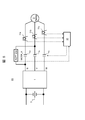
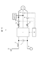
- FIG. 1 is a configuration diagram showing an example of the present device 61 according to the first embodiment.
- the inverter device 1 is composed of a current control element capable of conducting or blocking the current flowing from the high voltage side to the low voltage side, and a diode capable of conducting the current in the direction opposite to the current control element.
- a power semiconductor element such as an IGBT (Insulated Gate Bipolar Transistor; Insulated Gate Bipolar Transistor) or a power MOSFET (Metal Oxide Semiconductor Field Effect Transistor; Metal Oxide Semiconductor Field Effect Transistor) is used.
- IGBT Insulated Gate Bipolar Transistor
- MOSFET Metal Oxide Semiconductor Field Effect Transistor; Metal Oxide Semiconductor Field Effect Transistor
- the current control element used in the inverter device 1 according to the present invention may also be one using SiC or GaN.
- the inverter device 1 converts the DC power output from a DC power source (not shown) into three-phase AC power to drive the AC motor 2.
- the DC power supply input to the inverter device 1 is a DC power supply input unit of the inverter device, in which a smoothing capacitor 3 is connected in parallel with the inverter device 1 and is connected to a higher-level DC power supply via the smoothing capacitor 3.
- the AC motor 2 may be described as a load.
- FIG. 1 shows a configuration in which the inverter device 1 drives one AC motor 2, the inverter device 1 may be configured to drive a plurality of AC motors 2.
- PMSM_2' is designated by a reference numeral 2'.
- ACPT_11a to 11c and MCOK_A_4a to 4c for detecting the current value of each phase are provided on the AC output side of the inverter device 1.
- MCOK_A_4a to 4c are collectively referred to as MCOK_A_4
- ACPT_11a to 11c are collectively referred to as ACPT_11.
- the control device 31 takes in the detection output of the ACPT_11 and operates the switching operation of each current control element of the inverter device 1 so that the AC motor 2 has a desired torque output based on the detection output.
- MCOK_A_4 connects and disconnects the main circuit contacts that electrically connect each of the three phases of the inverter device 1 and the AC motor 2 in accordance with the release command output from the control device 31. Further, each phase may be individually charged and released, or a plurality of phases may be interlocked and charged and released.
- ACPT_11 may be configured to be provided only in the two phases of ACPT_11a and 11c, for example. That is, it is not always necessary to detect the currents of all three phases, and even if any two of the three phases are detected and the remaining one phase is calculated by assuming that the three-phase currents are in an equilibrium state. good.
- ACPT_21a between the phases is further provided on the AC motor 2 side (between the U phase and the V phase in the example of FIG. 1), and the voltage between the phases, that is, the voltage between the terminals of the AC motor is detected.
- the control device 31 or the like takes in the detected value of the ACPT_21a, and when the AC motor 2 is PMSM_2'or the like, after confirming the terminal voltage, controls the output of the inverter device 1 to stably serve as an inverter. The operation can be started.
- connection order of the inverter device 1, the AC motor 2, MCOK_A_4, the current detector 11, and ACPT_21a is configured in the order of the inverter device 1, MCOK_A_4, ACPT_21a, the current detectors 11a to 11c, and the AC motor 2. ing.
- the ACPT_21a is short-circuited (in the case of FIG. 1) even when the MCOK_A_4 is released and the inverter device 1 and the AC motor 2 are electrically disconnected from each other.
- the short circuit between the U phase and the V phase), the short circuit current flowing through the path from the AC motor 2 to the ACPT_21a can be detected by the current detectors 11a and 11b.
- the apparatus 61 can detect not only a short-circuit failure of ACPT_21a but also a phase-to-phase short circuit due to coil burnout or insulation deterioration of the AC motor 2 and wiring.
- This device 61 is suitable for applications such as a drive device for railway vehicles. In that application, when such a short-circuit current is detected, it is possible to deliver information to a higher-level device such as a driver's cab that the short-circuit current is flowing even if all of MCOK_A_4 are released. When the information arrives at the driver's cab, the driver etc. can take security measures based on the information. Specifically, it is possible to stop the operation of the relevant vehicle and prevent the damage from equipment failure from spreading.
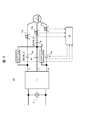
- FIG. 2 is a configuration diagram showing the present device 62 according to a modified example in which the connection form of ACPT_21a is different from that of the present device 61 of FIG.
- FIG. 1 shows an example in which ACPT_21a is connected to one place between the U phase and the V phase, but as shown in FIG. 2 (control device 31 is not shown), the U phase and the V phase are shown.
- a voltage detector may be connected between two or more phases including the space (ACPT_21a) and the space between the V phase and the W phase (ACPT_21b).
- FIG. 3 is a configuration diagram illustrating different inverter units 6 in order to explain the present device 61 according to the first embodiment
- FIG. 3 (a) shows (a) inserting (connecting) only the current detector 11 into each phase.
- FIG. 3B shows ACPT_21a arranged between the phases.
- FIG. 3A shows an example of a unit configuration of a general drive device of a railway vehicle, and the smoothing capacitor 3, the inverter device 1, and the current detector 11 are built in the inverter unit 6 by a housing or the like. It is a configuration.
- the inverter unit 6 is mainly composed of a portion surrounded by a dotted frame in FIG. 3A.
- the insertion means that it is connected to the circuit.
- the inverter unit 6 includes a smoothing capacitor 3, an inverter device 1, a current detector 11c, and ACPT_21a.
- a vehicle using an induction motor for the conventional AC motor 2 may be replaced with the PMSM_2'while maintaining compatibility while keeping the housing dimensions and shape of the inverter unit 6 as they are.
- the drive device of a railway vehicle is updated, MCOK_A_4 and ACPT_21a are increased as built-in devices in the inverter unit 6.
- FIGS. 1, 2 and 3 are schematic explanatory views of the arrangement of the inverter unit on a railroad vehicle
- FIG. 4A is a comparative example
- FIG. 4B is a comparison device 61b in which MCOK is added to FIG. 4A
- FIG. 4C. 1 is a simplified version of the equipment provided by the present device 61 shown in FIGS. 1, 2 and 3 (b).
- FIG. 4A shows a schematic example of mounting the inverter unit 6 on a railroad vehicle, and shows an example of equipment arrangement inside the conventional inverter unit 6.
- the current detector 11 may be arranged near the terminal for external output in the inverter unit 6 due to the limitation of the equipment mounting space in the inverter unit 6. is there.
- the connection order of the devices is the same as that shown in FIG. 10, the order is the inverter device 1, the current detector 11, and MOCK_4.
- the comparison device 61b of FIG. 4B the equipment in the inverter unit 6 becomes complicated.
- the inverter unit 6 is shown in the present device 61c of FIG. 4 (c).
- the equipment inside can be simplified. As a result, it is possible to simplify the replacement of a vehicle using an induction motor for the conventional AC motor 2 with the PMSM_2'while maintaining compatibility while maintaining the housing dimensions and shape of the inverter unit 6. It has the effect of saving labor.
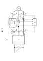
- FIG. 5 is a configuration diagram of the present device 62 according to the second embodiment.
- one connection terminal of ACPT_21a is connected between the inverter device 1 and MCOK_A_4a in the U-phase circuit with respect to the device 61 of the first embodiment. different.
- the apparatus 62 of the second embodiment shown in FIG. 5 can cut off the short-circuit current.
- a short-circuit current flows between the ACPT_21a and the AC motor 2 when the ACPT_21a is short-circuited.
- This short-circuit current is detected by the current detectors 11a and 11b and input to the control device 31.
- the control device 31 If the short-circuit current is input to the control device 31, for example, the operator can manually take security measures in the driver's cab of the electric car, or the control device 31 can automatically take security measures. That is, when the short-circuit current becomes equal to or higher than a predetermined current value, the control device 31 outputs a release command to MCOK_A_4a to 4c (particularly 4a and 4b in the case of FIG. 5). As a result, the short-circuit current can be cut off by the release operation of MCOK_A_4a to 4c (particularly 4a and 4b in the case of FIG. 5).
- FIG. 5 is only an example of the configuration of the present device 62. That is, one connection point (terminal) of the voltage detector 21 is connected between the inverter device 1 of the U-phase circuit and MCOK_A_4a. Further, the other connection point (terminal) of ACPT_21a is connected between MCOK_A_4b of the V-phase circuit and the current detector 11b.
- connection relationship between the U phase and the V phase may be reversed with respect to this configuration example. That is, regarding the connection points of ACPT_21a connected to two of the three phases, one may be connected between the inverter device 1 and MCOK_A, and the other may be connected between MCOK_A and the current detector.
- FIG. 6 is a configuration diagram of the present device 63 according to the second embodiment.
- the apparatus 63 of the third embodiment shown in FIG. 6 is provided with a first MCOK_A_4b and a second MCOK_B_5b only in the V phase with respect to the apparatus 62 of the second embodiment shown in FIG. The difference is that it has a step opening and closing configuration.
- the second MCOK_B_5b is inserted between the connection point of ACPT_21a and the current detector 11b. That is, the connection point on the V-phase side of ACPT_21a is connected so as to coincide with the connection point of the first MCOK_A_4b and the second MCOK_B_5b.
- the apparatus 63 of the third embodiment shown in FIG. 6 further shows an example in which the voltage detector 21b is also arranged between the V phase and the W phase.
- the connection point on the V-phase side of the voltage detector 21b is connected so as to coincide with the connection point between the first MCOK_A_4b and the second MCOK_B_5b.
- the device 63 can cut off the ground fault circuit (that is, the ground fault current).
- the ground fault current is detected by the current detector 11b and input to the control device 31.
- the control device 31 When the ground fault current detected by the control device 31 exceeds a predetermined value, the control device 31 outputs a release command to the second MCOK_B_5b. As a result, the second MCOK_B_5b is released, and the ground fault circuit (that is, the ground fault current) can be cut off.
- FIG. 7 is a configuration diagram of the present device 64 according to the third embodiment.
- a second MCOK_B_5a to 5c is inserted between the current detectors 11a to 11c and the AC motor 2 with respect to the apparatus 61 of the first embodiment.
- the difference is that all three phases of, V, and W are opened and closed in series in two stages.
- the effect of continuing the operation is more certain by interrupting the above-mentioned short-circuit current.
- the present devices 61 and 62 of the first embodiment shown in FIGS. 1, 2 and 3 (b) will be described in comparison with each other.
- the ACPT_21a when the ACPT_21a is short-circuited, a short-circuit current flows between the ACPT_21a and the AC motor 2, and the short-circuit current detected by the current detectors 11a and 11b is input to the control device 31.
- the operation can be continued in a railway vehicle or the like to which this device 64 is applied. That is, since a plurality of the same circuits are configured in a drive device for a railway vehicle or the like, it is possible to continue operation with the other drive devices left by disconnecting only the failed drive device.
- the control device 31 outputs a release command to the second MCOK_B_5a to 5c.
- the short-circuit current due to the short-circuit failure of ACPT_21a is particularly effective by releasing the 5a and 5b.
- the second MCOK_B_5 provided on the side of the AC motor 2 (PMSM_2') is turned on when the inverter device 1 is started ( After closing the circuit), the first MCOK_A_4 is charged.
- the second MCOK_B_5 is turned on first, the interphase voltage (voltage between terminals) of the AC motor 2 is detected by ACPT_21a, and the rotor position and speed of the motor are estimated.
- the first MCOK_A is turned on with the inverter device 1 activated by the control device 31.
- operations such as overcurrent and torque vibration can be prevented, and operation as an inverter can be started stably.
- FIG. 8 is a configuration diagram of the present device 65 according to the fifth embodiment.
- Example 5 The apparatus 65 shown in FIG. 8 has the following differences from the apparatus 64 of the fourth embodiment shown in FIG. 7. That is, in the present device 65, the current detectors 11a to 11c are provided on the side of the AC motor 2'from the second MCOK_B_5a to 5c.
- one of the two phases connecting the ACPT_21a (the U phase side in FIG. 8) is connected between the first MCOK_A_4a and the second MCOK_B_5a. Further, in the apparatus 65, one phase on the other side (V phase in FIG. 8) is connected between the second MCOK_B_5b and the current detector 11b.
- the device 65 having such a configuration can stably start the operation as an inverter and the safety is improved as in the device 64 of the fourth embodiment shown in FIG. 7. That is, the present device 65 can prevent operations such as overcurrent and torque vibration by the charging order of the first MCOK_A_4a to 4c and the second MCOK_B_5a to 5c.
- the operation as an inverter can be started stably.
- the current detectors 11a to 11c are arranged in the immediate vicinity of the AC motor 2 (2'), it becomes possible to detect the short-circuit current due to the short-circuit failure on the AC motor side, and the safety is improved. improves.
- the AC motor 2 of the present devices 61 to 65 shown in FIGS. 1 to 8 was either an induction motor or PMSM_2, but in the comparison devices 71 and 72 of FIGS. 9 and 10, PMSM_2'is used. Since the explanation is limited, the code of the electric motor is distinguished as 2'.
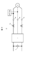
- FIG. 9 is a configuration diagram of a drive device for a three-phase AC motor (comparison device 71) according to Comparative Example 1.
- the comparison device 71 shown as Comparative Example 1 in FIG. 9 different current detectors 11a and 11b and MCOK_A_4a to 4c are inserted in the connection wiring between the inverter device 1 and PMSM_2'.
- ACPT_21a is arranged between the phases.
- connection order of these devices is such that the current detectors 11a and 11b are inserted closer to the inverter device 1 from the inverter device 1 to the PMSM_2'with the MCOK_4_4a to 4c as the boundary. It is far from PMSM_2'. Therefore, it is not possible to measure the regenerative current of PMSM_2'when MCOK_A_4a-4c is released.
- ACPT_21a is arranged on the side close to PMSM_2'with MCOK_A_4a to 4c as a boundary. Therefore, it is possible to measure the regenerative voltage of PMSM_2'when MCOK_A_4a to 4c are released, but when ACPT_21a is short-circuited, it is difficult to isolate the failed part only by operating from the driver's cab. As a result, we have no choice but to abandon the continuation of train operation with other healthy power.
- FIG. 10 is a block diagram of the comparison device 72.
- the comparison device 72 shown as Comparative Example 2 in FIG. 10 illustrates the use of a railway vehicle as a general DC electric vehicle. If the comparison device 72 is a DC electric vehicle, one is connected to a DC train line and the other is connected to a grounded portion such as a wheel.
- the DC power supply upper side of the smoothing capacitor 3 is connected to the DC train line via the smoothing reactor 51 and the pantograph 52 which is a current collector.
- the current detectors 11a and 11b and MCOK_A_4a and 4c for each phase are inserted in the connection wiring between the inverter device 1 and PMSM_2', and ACPT_21a is arranged between the phases. Has been done.
- the current detectors 11a and 11b are provided between the inverter device 1 and the MCOK_A_4a, 4c or ACPT_21a. Common. Therefore, the regenerative current of PMSM_2'cannot be measured by the current detectors 11a and 11b when MCOK_A_4a to 4c are released.
- the comparison device 72 of FIG. 10 and the comparison device 71 of FIG. 9 are different in the following points. That is, of the three MCOK_A_4a to 4c in the comparison device 72, only one MCOK_A_4b has a circuit configuration in which is inserted between ACPT_21a and PMSM_2'. Further, the current detectors 11a and 11b are arranged on the side closer to the inverter device 1 with the MCOK_A_4b as a boundary, and are far from the PMSM_2'.
- the comparison device 72 of FIG. 10 cannot measure both the regenerative voltage and the regenerative current of PMSM_2'when MCOK_A_4a to 4c are released.
- ACPT_21a has a short-circuit failure, it is possible to disconnect the failure point only by operating from the driver's cab. As a result, it is possible to continue operating the train with other healthy power.
- the devices 61 to 65 can be summarized as follows.
- the devices 61 and 62 of the first embodiment shown in FIGS. 1 and 2 and 3 (b) are typical examples.
- the devices 61 and 62 are drive devices for a three-phase AC motor that drive the three-phase AC motor 2 as a load by the inverter device 1.
- the inverter device 1 used for this has a plurality of current control units, converts DC power supplied from a power source into U, V, W-phase three-phase AC power, and drives a load.
- the current control unit is a combination of a current control element and a rectifying element.
- the current control element conducts or cuts off the current flowing in one direction.
- the rectifying element is connected in parallel to the current control element to conduct current in the direction opposite to that of the current control element.
- a motor opening switch MCOK_A_4 is connected between the inverter device 1 and the load, and the inverter device 1 and the load are electrically connected or disconnected by the MCOK_A_4. You can distinguish between doing and doing.
- each terminal of the voltage detector ACPT_21a having one-to-two terminals is connected to at least two-phase circuits such as U-phase and V-phase.
- U-phase and V-phase In order to detect the voltage between the U, V, and W phases, it is sufficient to have one ACPT_21a shown in FIG. 1 or two ACPT_21a, 21b shown in FIG.
- a current detector 11 for detecting the three-phase phase current supplied from the inverter device 1 to the load is connected to each of the U, V, and W phases.
- the circuit configuration from the inverter device 1 to the load is as follows. That is, the connection order of each device of the inverter device 1, load, MCOK_A_4, current detector 11, and ACPT_21a is such that MCOK_A is closest to the inverter device 1, then CCPT_21a, then the current detector 11, and then the load. , And so on.
- MCOK_A_4 is released when ACPT_21a is short-circuited (for example, short-circuited in the U phase and V phase in FIG. 1).
- the inverter device 1 and the AC motor 2 are electrically disconnected.
- the short-circuit current flowing through the path between the AC motor 2 and ACPT_21a can be detected by the current detectors 11a and 11b.
- the information can also be delivered to the driver's cab in real time. As a result, it is easy for drivers and the like to take optimal security measures.
- the load of the devices 61 and 62 is PMSM_2', which is applied to a railway vehicle, for example, and is applicable to a short-circuit failure of ACPT_21a and a failure such as a decrease in the output of the inverter device 1. To do. In that case, there may be an optimum security measure by a driver or the like that eliminates the regenerative braking action of PMSM_2'and continues the operation with other residual power.
- the following conveniences can be obtained by the configuration of the devices 61 and 62. That is, if the load at the beginning of the design is an induction motor, MCOK is unnecessary because the regenerative braking action is small, and when the load is not already installed in the inverter device 1, the load is replaced from the induction motor to PMSM_2'.
- the basic design may be sufficient so that the required MCOK and ACPT_21a are arranged in this order in the immediate vicinity of the inverter device 1.
- the current detector 11 is arranged in the immediate vicinity of the load so as to avoid the space.
- the current detector 11 is arranged in the immediate vicinity of the load so as to avoid the space.
- the MCOK_A_4 is connected between the connection point between the inverter device 1 and the voltage detector ACPT_21a. preferable.
- the advantage of MCOK_A_4 being arranged in the immediate vicinity of the inverter device 1 is as described above.
- connection form of the two-phase circuit connecting the ACPT_21a is as follows.
- MCOK_A_4a is connected between the connection point of ACPT_21a and the current detector 11a.
- MCOK_A_4b is connected between the connection point of the inverter device 1 and ACPT_21a.
- control device 31 shown in FIG. 5 maintains a state in which each phase current value can be detected by the current detectors 11a to 11c even if the ACPT_21a fails, so that it is possible to take considerable security measures. It's easy.
- MCOK_A_4b is connected as a first motor opening switch between the inverter device 1 and the connection point of ACPT_21a in the V phase. ing. In this V phase, MCOK_B_5b is connected between the connection point of ACPT_21a and the current detector 11b as a second motor opening switch.
- the current detector 11b maintains a state in which the V-phase ground fault current can be detected. It is also easy to take considerable security measures.
- the apparatus 64 of the fourth embodiment shown in FIG. 7 is provided with MCOK_B_5 as a second motor opening switch between the current detector 11 and the load.
- MCOK_A_4 as the first motor opening switch and MCOK_B_5 as the second motor opening switch constitute a series two-stage switch.
- the control device 31 shown in FIG. 7 maintains a state in which the current detectors 11a and 11b can detect the regenerative current even if a regenerative braking state occurs due to a short-circuit failure of the ACPT_21a in, for example, a vehicle equipped with PMSM_2'. Will be done. At that time, if the control device 31 releases MCOK_B_5, it is easy to take considerable security measures.
- the inverter device 1 when the inverter device 1 is started, if only the second MCOK_B_5 provided on the PMSM_2'side is turned on (closed) and the ACPT_21a detects the phase-to-phase voltage (terminal-to-terminal voltage) of the PMSM_2'2, the electric motor Estimate the rotor position and velocity of. After that, based on the estimated position and speed information, the first MCOK_A is turned on with the inverter device 1 started by the control device 31. As a result, operations such as overcurrent and torque vibration can be prevented, and operation as an inverter can be started stably.
- the apparatus 65 of the fifth embodiment shown in FIG. 8 has a two-stage series with a first MCOK_A_4 and a second MCOK_B_5 in each phase between the inverter device 1 and the current detectors 11a to 11c. Each has a switch. Further, the U-phase circuit of one of the two phases to which the voltage detector ACPT_21a is connected is connected between the first MCOK_A_4 and the second MCOK_B_5. The other V-phase circuit is connected between the second MCOK_5b and the current detector 11b.
- the apparatus 65 having such a configuration can start the operation of the apparatus 64 of the fourth embodiment shown in FIG. 7 as an inverter more highly stably, and the safety is improved. That is, the present device 65 can prevent operations such as overcurrent and torque vibration by the charging order of the first MCOK_A_4a to 4c and the second MCOK_B_5a to 5c. Further, in the present device 65, since the current detectors 11a to 11c are arranged in the immediate vicinity of the AC motor 2, it becomes possible to detect a short-circuit current due to a short-circuit failure on the AC motor side, and the safety is improved.
- 1 Inverter device 2 Three-phase AC motor (as load), 2'(PMSM as load) Permanent magnet type synchronous motor, 4, 4a-4c, 1st motor opening switch (MCOK_A), 5, 5a- 5c 2nd motor opening switch (MCOK_B), 11, 11a to 11c current detector, 21a, 21b voltage detector (ACPT), 31 control device, 61 to 65 three-phase AC motor drive device (this device)
Landscapes
- Engineering & Computer Science (AREA)
- Power Engineering (AREA)
- Life Sciences & Earth Sciences (AREA)
- Sustainable Development (AREA)
- Sustainable Energy (AREA)
- Transportation (AREA)
- Mechanical Engineering (AREA)
- Control Of Ac Motors In General (AREA)
- Electric Propulsion And Braking For Vehicles (AREA)
- Inverter Devices (AREA)
Priority Applications (4)
| Application Number | Priority Date | Filing Date | Title |
|---|---|---|---|
| JP2021525924A JP7111901B2 (ja) | 2019-06-14 | 2020-04-10 | 三相交流電動機用駆動装置、それを備えた鉄道車両、及び三相交流電動機の駆動方法 |
| CN202080043212.1A CN114026780B (zh) | 2019-06-14 | 2020-04-10 | 三相交流电动机用驱动装置、具备该驱动装置的铁道车辆以及三相交流电动机的驱动方法 |
| US17/596,529 US11701971B2 (en) | 2019-06-14 | 2020-04-10 | Three-phase AC motor drive device, rail vehicle equipped with same, and three-phase AC motor drive method |
| EP20820768.8A EP3985863B1 (en) | 2019-06-14 | 2020-04-10 | Three-phase ac motor drive device, rail vehicle equipped with same, and three-phase ac motor drive method |
Applications Claiming Priority (2)
| Application Number | Priority Date | Filing Date | Title |
|---|---|---|---|
| JP2019111338 | 2019-06-14 | ||
| JP2019-111338 | 2019-06-14 |
Publications (1)
| Publication Number | Publication Date |
|---|---|
| WO2020250561A1 true WO2020250561A1 (ja) | 2020-12-17 |
Family
ID=73781390
Family Applications (1)
| Application Number | Title | Priority Date | Filing Date |
|---|---|---|---|
| PCT/JP2020/016158 Ceased WO2020250561A1 (ja) | 2019-06-14 | 2020-04-10 | 三相交流電動機用駆動装置、それを備えた鉄道車両、及び三相交流電動機の駆動方法 |
Country Status (5)
| Country | Link |
|---|---|
| US (1) | US11701971B2 (https=) |
| EP (1) | EP3985863B1 (https=) |
| JP (1) | JP7111901B2 (https=) |
| CN (1) | CN114026780B (https=) |
| WO (1) | WO2020250561A1 (https=) |
Cited By (1)
| Publication number | Priority date | Publication date | Assignee | Title |
|---|---|---|---|---|
| JP7485472B1 (ja) | 2023-01-24 | 2024-05-16 | 東芝エレベータ株式会社 | エレベータシステム |
Families Citing this family (1)
| Publication number | Priority date | Publication date | Assignee | Title |
|---|---|---|---|---|
| DE102022200378A1 (de) * | 2022-01-14 | 2023-07-20 | Siemens Mobility GmbH | Verfahren zum Steuern eines Antriebssystems eines Schienenfahrzeugs |
Citations (4)
| Publication number | Priority date | Publication date | Assignee | Title |
|---|---|---|---|---|
| JP2007318969A (ja) * | 2006-05-29 | 2007-12-06 | Toshiba Corp | 電気車制御装置 |
| JP2011078254A (ja) | 2009-09-30 | 2011-04-14 | Toshiba Corp | 電気車制御装置 |
| JP2013192300A (ja) | 2012-03-12 | 2013-09-26 | Toshiba Corp | 永久磁石電動機駆動装置 |
| JP2016178735A (ja) * | 2015-03-18 | 2016-10-06 | 株式会社東芝 | 鉄道車両用駆動制御装置 |
Family Cites Families (14)
| Publication number | Priority date | Publication date | Assignee | Title |
|---|---|---|---|---|
| JPH10337091A (ja) * | 1997-05-28 | 1998-12-18 | Fuji Electric Co Ltd | 電動機駆動用インバータの再始動制御方法 |
| JP4709580B2 (ja) * | 2005-04-27 | 2011-06-22 | 株式会社東芝 | 鉄道車両駆動制御装置 |
| JP4738080B2 (ja) * | 2005-07-20 | 2011-08-03 | 株式会社東芝 | 鉄道車両駆動制御装置 |
| JP2007318968A (ja) | 2006-05-29 | 2007-12-06 | Toshiba Corp | 電気車制御装置 |
| KR101066700B1 (ko) * | 2006-10-19 | 2011-09-21 | 미쓰비시덴키 가부시키가이샤 | 전력 변환 장치 |
| WO2009001468A1 (ja) | 2007-06-28 | 2008-12-31 | Mitsubishi Electric Corporation | 電力変換装置 |
| EP2151347A1 (en) * | 2008-08-07 | 2010-02-10 | Bombardier Transportation GmbH | Arrangement for generating a traction force of a track bound vehicle |
| JP5504748B2 (ja) * | 2009-08-20 | 2014-05-28 | 富士電機株式会社 | インバータ装置 |
| ES2602809T3 (es) * | 2009-12-28 | 2017-02-22 | Mitsubishi Electric Corporation | Dispositivo de control de accionamiento de motor de corriente alterna |
| US9160271B2 (en) * | 2012-01-18 | 2015-10-13 | Mitsubishi Electric Corporation | Power conversion device |
| JPWO2014112127A1 (ja) * | 2013-01-21 | 2017-01-19 | 株式会社東芝 | 鉄道車両用駆動制御装置 |
| FR3032397B1 (fr) * | 2015-02-06 | 2018-10-12 | Alstom Transport Technologies | Systeme de protection de la chaine de traction d'un vehicule ferroviaire, ligne de transmission et vehicule ferroviaire associes |
| DE102015206561A1 (de) * | 2015-04-13 | 2016-10-13 | Siemens Aktiengesellschaft | Antriebschutzvorrichtung zum Schützen eines Fahrantriebs |
| KR102478880B1 (ko) * | 2021-01-13 | 2022-12-16 | 엘지전자 주식회사 | 모터 구동 장치 및 이를 구비하는 공기조화기 |
-
2020
- 2020-04-10 WO PCT/JP2020/016158 patent/WO2020250561A1/ja not_active Ceased
- 2020-04-10 EP EP20820768.8A patent/EP3985863B1/en active Active
- 2020-04-10 US US17/596,529 patent/US11701971B2/en active Active
- 2020-04-10 JP JP2021525924A patent/JP7111901B2/ja active Active
- 2020-04-10 CN CN202080043212.1A patent/CN114026780B/zh active Active
Patent Citations (4)
| Publication number | Priority date | Publication date | Assignee | Title |
|---|---|---|---|---|
| JP2007318969A (ja) * | 2006-05-29 | 2007-12-06 | Toshiba Corp | 電気車制御装置 |
| JP2011078254A (ja) | 2009-09-30 | 2011-04-14 | Toshiba Corp | 電気車制御装置 |
| JP2013192300A (ja) | 2012-03-12 | 2013-09-26 | Toshiba Corp | 永久磁石電動機駆動装置 |
| JP2016178735A (ja) * | 2015-03-18 | 2016-10-06 | 株式会社東芝 | 鉄道車両用駆動制御装置 |
Cited By (1)
| Publication number | Priority date | Publication date | Assignee | Title |
|---|---|---|---|---|
| JP7485472B1 (ja) | 2023-01-24 | 2024-05-16 | 東芝エレベータ株式会社 | エレベータシステム |
Also Published As
| Publication number | Publication date |
|---|---|
| US11701971B2 (en) | 2023-07-18 |
| CN114026780B (zh) | 2025-02-25 |
| EP3985863A1 (en) | 2022-04-20 |
| JP7111901B2 (ja) | 2022-08-02 |
| US20220234450A1 (en) | 2022-07-28 |
| CN114026780A (zh) | 2022-02-08 |
| EP3985863B1 (en) | 2025-08-27 |
| JPWO2020250561A1 (https=) | 2020-12-17 |
| EP3985863A4 (en) | 2023-07-05 |
Similar Documents
| Publication | Publication Date | Title |
|---|---|---|
| US8688301B2 (en) | Power converter | |
| JP4120708B2 (ja) | 電力変換装置 | |
| EP2418116B1 (en) | Drive control system | |
| US11070161B2 (en) | Electric-motor driving device and refrigeration-cycle application apparatus including electric-motor driving device | |
| JP6064657B2 (ja) | 回転電機駆動装置 | |
| JP2009065828A (ja) | 不十分な電気制動を検出して安全ブレーキに転流する安全装置 | |
| WO2015152002A1 (ja) | インバータ制御装置 | |
| JP7111901B2 (ja) | 三相交流電動機用駆動装置、それを備えた鉄道車両、及び三相交流電動機の駆動方法 | |
| JP4709580B2 (ja) | 鉄道車両駆動制御装置 | |
| JPWO2020250561A5 (https=) | ||
| JP4382571B2 (ja) | 鉄道車両駆動制御装置 | |
| JP5481088B2 (ja) | 鉄道車両駆動制御装置 | |
| JP2012090380A (ja) | 車両用駆動制御装置 | |
| ES2938854T3 (es) | Instalación con un consumidor eléctrico | |
| JP2005117797A (ja) | 鉄道車両駆動制御装置 | |
| RU2401504C1 (ru) | Преобразователь электрической мощности | |
| CN113572345B (zh) | 用于整流器的电路总成、整流器、电的机器和用于运行电的机器的方法 | |
| JP2002247703A (ja) | 交流電気車の電力変換装置 | |
| JP2005184951A (ja) | 埋込磁石同期モータとその駆動方法 |
Legal Events
| Date | Code | Title | Description |
|---|---|---|---|
| 121 | Ep: the epo has been informed by wipo that ep was designated in this application |
Ref document number: 20820768 Country of ref document: EP Kind code of ref document: A1 |
|
| ENP | Entry into the national phase |
Ref document number: 2021525924 Country of ref document: JP Kind code of ref document: A |
|
| NENP | Non-entry into the national phase |
Ref country code: DE |
|
| WWE | Wipo information: entry into national phase |
Ref document number: 2020820768 Country of ref document: EP |
|
| WWG | Wipo information: grant in national office |
Ref document number: 202080043212.1 Country of ref document: CN |
|
| WWG | Wipo information: grant in national office |
Ref document number: 2020820768 Country of ref document: EP |