WO2020250429A1 - 電力変換装置及び電動機制動方法 - Google Patents
電力変換装置及び電動機制動方法 Download PDFInfo
- Publication number
- WO2020250429A1 WO2020250429A1 PCT/JP2019/023697 JP2019023697W WO2020250429A1 WO 2020250429 A1 WO2020250429 A1 WO 2020250429A1 JP 2019023697 W JP2019023697 W JP 2019023697W WO 2020250429 A1 WO2020250429 A1 WO 2020250429A1
- Authority
- WO
- WIPO (PCT)
- Prior art keywords
- inverter
- electric motor
- power
- current
- control unit
- Prior art date
- Legal status (The legal status is an assumption and is not a legal conclusion. Google has not performed a legal analysis and makes no representation as to the accuracy of the status listed.)
- Ceased
Links
Images

Classifications
-
- H—ELECTRICITY
- H02—GENERATION; CONVERSION OR DISTRIBUTION OF ELECTRIC POWER
- H02M—APPARATUS FOR CONVERSION BETWEEN AC AND AC, BETWEEN AC AND DC, OR BETWEEN DC AND DC, AND FOR USE WITH MAINS OR SIMILAR POWER SUPPLY SYSTEMS; CONVERSION OF DC OR AC INPUT POWER INTO SURGE OUTPUT POWER; CONTROL OR REGULATION THEREOF
- H02M5/00—Conversion of AC power input into AC power output, e.g. for change of voltage, for change of frequency, for change of number of phases
- H02M5/40—Conversion of AC power input into AC power output, e.g. for change of voltage, for change of frequency, for change of number of phases with intermediate conversion into DC
- H02M5/42—Conversion of AC power input into AC power output, e.g. for change of voltage, for change of frequency, for change of number of phases with intermediate conversion into DC by static converters
- H02M5/44—Conversion of AC power input into AC power output, e.g. for change of voltage, for change of frequency, for change of number of phases with intermediate conversion into DC by static converters using discharge tubes or semiconductor devices to convert the intermediate DC into AC
- H02M5/453—Conversion of AC power input into AC power output, e.g. for change of voltage, for change of frequency, for change of number of phases with intermediate conversion into DC by static converters using discharge tubes or semiconductor devices to convert the intermediate DC into AC using devices of a triode or transistor type requiring continuous application of a control signal
- H02M5/458—Conversion of AC power input into AC power output, e.g. for change of voltage, for change of frequency, for change of number of phases with intermediate conversion into DC by static converters using discharge tubes or semiconductor devices to convert the intermediate DC into AC using devices of a triode or transistor type requiring continuous application of a control signal using semiconductor devices only
-
- H—ELECTRICITY
- H02—GENERATION; CONVERSION OR DISTRIBUTION OF ELECTRIC POWER
- H02M—APPARATUS FOR CONVERSION BETWEEN AC AND AC, BETWEEN AC AND DC, OR BETWEEN DC AND DC, AND FOR USE WITH MAINS OR SIMILAR POWER SUPPLY SYSTEMS; CONVERSION OF DC OR AC INPUT POWER INTO SURGE OUTPUT POWER; CONTROL OR REGULATION THEREOF
- H02M1/00—Details of apparatus for conversion
- H02M1/0003—Details of control, feedback or regulation circuits
- H02M1/0009—Devices or circuits for detecting current in a converter
-
- H—ELECTRICITY
- H02—GENERATION; CONVERSION OR DISTRIBUTION OF ELECTRIC POWER
- H02M—APPARATUS FOR CONVERSION BETWEEN AC AND AC, BETWEEN AC AND DC, OR BETWEEN DC AND DC, AND FOR USE WITH MAINS OR SIMILAR POWER SUPPLY SYSTEMS; CONVERSION OF DC OR AC INPUT POWER INTO SURGE OUTPUT POWER; CONTROL OR REGULATION THEREOF
- H02M7/00—Conversion of AC power input into DC power output; Conversion of DC power input into AC power output
- H02M7/42—Conversion of DC power input into AC power output without possibility of reversal
- H02M7/44—Conversion of DC power input into AC power output without possibility of reversal by static converters
- H02M7/48—Conversion of DC power input into AC power output without possibility of reversal by static converters using discharge tubes with control electrode or semiconductor devices with control electrode
- H02M7/483—Converters with outputs that each can have more than two voltages levels
- H02M7/49—Combination of the output voltage waveforms of a plurality of converters
-
- H—ELECTRICITY
- H02—GENERATION; CONVERSION OR DISTRIBUTION OF ELECTRIC POWER
- H02P—CONTROL OR REGULATION OF ELECTRIC MOTORS, ELECTRIC GENERATORS OR DYNAMO-ELECTRIC CONVERTERS; CONTROLLING TRANSFORMERS, REACTORS OR CHOKE COILS
- H02P3/00—Arrangements for stopping or slowing electric motors, generators, or dynamo-electric converters
- H02P3/06—Arrangements for stopping or slowing electric motors, generators, or dynamo-electric converters for stopping or slowing an individual dynamo-electric motor or dynamo-electric converter
- H02P3/18—Arrangements for stopping or slowing electric motors, generators, or dynamo-electric converters for stopping or slowing an individual dynamo-electric motor or dynamo-electric converter for stopping or slowing an AC motor
-
- H—ELECTRICITY
- H02—GENERATION; CONVERSION OR DISTRIBUTION OF ELECTRIC POWER
- H02P—CONTROL OR REGULATION OF ELECTRIC MOTORS, ELECTRIC GENERATORS OR DYNAMO-ELECTRIC CONVERTERS; CONTROLLING TRANSFORMERS, REACTORS OR CHOKE COILS
- H02P3/00—Arrangements for stopping or slowing electric motors, generators, or dynamo-electric converters
- H02P3/06—Arrangements for stopping or slowing electric motors, generators, or dynamo-electric converters for stopping or slowing an individual dynamo-electric motor or dynamo-electric converter
- H02P3/18—Arrangements for stopping or slowing electric motors, generators, or dynamo-electric converters for stopping or slowing an individual dynamo-electric motor or dynamo-electric converter for stopping or slowing an AC motor
- H02P3/22—Arrangements for stopping or slowing electric motors, generators, or dynamo-electric converters for stopping or slowing an individual dynamo-electric motor or dynamo-electric converter for stopping or slowing an AC motor by short-circuit or resistive braking
Definitions
- the present invention relates to a power converter and an electric motor braking method.
- the power conversion device supplies AC power converted from DC power to the electric motor to drive the electric motor and the mechanical load linked to the rotation of the electric motor.
- regenerative energy is generated by the electromotive force.
- this regenerative energy flows from the electric motor into the power converter, the voltage on the DC side of the power converter (DC voltage) rises. At that time, when the overvoltage state of the DC voltage is avoided by using the discharge circuit, it may be difficult to stop the electric motor promptly.
- An object to be solved by the present invention is to provide a power conversion device and an electric motor braking method capable of braking an electric motor more quickly.
- the power conversion device of one aspect of the embodiment includes a diode converter, an inverter, a smoothing capacitor, a resistor, a current sensor, an estimation unit, and a control unit.
- the diode converter rectifies the alternating current from the power supply.
- the DC side is connected to the DC output of the diode converter
- the AC side is connected to the electric motor
- the semiconductor switching element that converts the DC power on the DC side into AC power is connected in antiparallel to the semiconductor switching element. It is equipped with a connection diode.
- the smoothing capacitor is provided at the DC output of the diode converter.
- the resistor is connected in parallel with the smoothing capacitor.
- the current sensor detects the load current flowing between the inverter and the electric motor.
- the estimation unit calculates an estimated value of the DC voltage Vdc on the DC side based on the current value I detected by the current sensor.
- the control unit controls the inverter so that the estimated value of the DC voltage Vdc on the DC side does not exceed a predetermined reference voltage during the period when the electric motor is in the regenerative state.
- positive electrode P and “negative electrode N” are defined first.
- the “positive electrode P” means a portion that becomes a positive potential when the power conversion device 1 is operating.
- the “negative electrode N” means a portion that becomes a negative potential when the power conversion device 1 is operating.
- the reference voltage Vdc0 of the DC link in the power conversion device 1 is specified as a predetermined voltage.
- the reference voltage Vdc0 is, for example, a voltage between the positive electrode P and the negative electrode N. This reference voltage Vdc0 is sometimes called the rated voltage of direct current (direct current link).
- the power conversion device 1 of the embodiment will be described with reference to FIGS. 1 to 3.
- the power conversion device 1 converts the AC power supplied from the AC power source 2 into DC power, converts the converted DC power into AC power having a desired frequency and voltage, and supplies the converted DC power to the electric motor 3.
- the electric motor 3 is, for example, a three-phase type induction motor, but is not limited thereto.
- the power supply side of the power conversion device 1 is connected to the AC power supply 2 via the circuit breaker 4.
- the circuit breaker 4 cuts off the electric power supplied from the AC power source 2 (power source) based on the control of the control device 7 described later.
- the circuit breaker 4 may be configured as a separate body from the power conversion device 1, or may be configured as a part of the power conversion device 1.
- the power conversion device 1 may include a three-phase converter and a three-phase inverter instead of the plurality of cell units 6s.
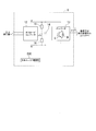
- FIG. 1 is a diagram showing an example of the power conversion device 1 of the embodiment.
- the electric circuit system is shown by a single line, and the switch and the like are not shown.
- the power conversion device 1 includes, for example, an input transformer 5, a plurality of cell units 6s, a control device 7, and a current sensor AM.
- the input transformer 5 transforms the voltage of the AC power supplied from the AC power supply 2 (primary side voltage) to a desired secondary side voltage, and transfers the AC power of the secondary side voltage to each of the plurality of cell units 6s. Supply to.
- the input transformer 5 has a primary winding and a plurality of groups of windings (secondary windings) insulated from each other. Insulation is also provided between the primary winding and the secondary winding.
- the plurality of cell units 6s include, for example, three load first phase cell units 6A1, 6A2, 6A3 (the descriptions in the figure are U1, U2, U3), and three load second phase cell units 6B1. Includes 6B1 (the description in the figure is V1, V2, V3), 6B3 and three load phase 3 cell units 6C1, 6C2, 6C3 (the description in the figure is W1, W2, W3).
- the cell units 6A1, 6A2, 6A3, 6B1, 6B1, 6B3, 6C1, 6C2, and 6C3 have the same circuit configuration, and when they are described without distinction, they are simply referred to as cell units 6.
- Each cell unit 6 converts the three-phase AC power supplied from the secondary winding of the input transformer 5 into DC power, and converts the converted DC power into AC power having a desired frequency and voltage for output. To do.
- the first group on the secondary side of the input transformer 5 is connected to the input of the cell unit 6A1.
- the second group on the secondary side of the input transformer 5 is connected to the input of the cell unit V1.
- the third group on the secondary side of the input transformer 5 is connected to the input of the cell unit W1.
- the fourth group on the secondary side of the input transformer 5 is connected to the input of the cell unit 6A2.
- the fifth group on the secondary side of the input transformer 5 is connected to the input of the cell unit 6B2.
- the sixth group on the secondary side of the input transformer 5 is connected to the input of the cell unit 6C2.
- the seventh group on the secondary side of the input transformer 5 is connected to the input of the cell unit 6A3.
- the eighth group on the secondary side of the input transformer 5 is connected to the input of the cell unit 6B3.
- the ninth group on the secondary side of the input transformer 5 is connected to the input of the cell unit 6C3.
- the outputs of the cell units 6A1, 6A2, and 6A3 are electrically connected to each other in series in the order shown.
- the output terminal of the cell unit 6A3 that is not connected to the cell unit 6A2 is connected to the first phase (U phase) of the electric motor 3.
- the output terminal that is not connected to the cell unit 6A2 of the cell unit 6A1 is connected to the neutral point.
- the outputs of the cell units 6B1, 6B2, and 6B3 are electrically connected to each other in series in the order shown.
- the output terminal of the cell unit 6B3 that is not connected to the cell unit 6B2 is connected to the second phase (V phase) of the electric motor 3.
- the output terminal that is not connected to the cell unit 6B2 of the cell unit 6B1 is connected to the neutral point.
- the outputs of the cell units 6C1, 6B2, and 6B3 are electrically connected to each other in series in the order shown.
- the output terminal of the cell unit 6C3 that is not connected to the cell unit 6C2 is connected to the third phase (W phase) of the electric motor 3.
- the output terminal that is not connected to the cell unit 6C2 of the cell unit 6C1 is connected to the neutral point.
- the power conversion device 1 can supply a large amount of AC power to the electric motor 3.
- the current sensor AM1 and the current sensor AM2 detect the load current (phase current) flowing between the inverter 13 (FIG. 2) of the power conversion device 1 and the electric motor 3.
- the current sensor AM1 is provided in the first phase of the AC output
- the current sensor AM2 is provided in the third phase of the AC output. Since the current of the second phase of the AC output can be obtained from the values of the current sensor AM1 and the current sensor AM2, it can be omitted.
- the current sensor AM1 and the current sensor AM2 are not distinguished from each other, they may be simply referred to as the current sensor AM.
- the current value detected by the current sensor AM may be referred to as current I.
- the control device 7 controls or protects each cell unit 6.
- the control device 7 includes, for example, a storage unit 71, an operation control unit 72, an estimation unit 73, and a braking control unit 74.
- the storage unit 71 stores various data related to the control of the plurality of cell units 6s.
- Various data include, for example, a limit value (threshold Vth) for limiting the overvoltage of the DC voltage of the cell unit 6, a reference voltage Vdc0 of the DC voltage of the cell unit 6, and a history of the current value I detected by the current sensor AM.
- the data, the integrated value data thereof, the estimated value of the DC voltage value Vdc of the cell unit 6 (hereinafter, referred to as the DC voltage value Vdc_est), and the like are included.
- the threshold value Vth is defined as, for example, an upper limit value of the DC voltage of the DC link.
- the reference voltage Vdc0 is an example of the control target voltage.
- the operation control unit 72 is a switching element included in each cell unit 6 based on the data stored in the storage unit 71, for example, the information indicating the DC voltage value Vdc_est and the information indicating the current I detected by the current sensor AM.
- a control signal for controlling 13S (FIG. 2) is generated.
- the operation control unit 72 controls each cell unit 6 by sending the generated control signal to each cell unit 6.
- the operation control unit 72 acquires a signal indicating the control state of the electric motor 3 (for example, a feedback signal of the rotation speed), and controls each cell unit 6 based on the feedback signal. Further, the control device 7 acquires a control command signal of the electric motor 3 from another device, and controls each cell unit 6 based on the control command signal.
- the estimation unit 73 calculates the DC voltage value Vdc_est based on the current value I detected by the current sensor AM. The calculation of the DC voltage value Vdc_est will be described later.
- the braking control unit 74 controls each unit so as to brake the electric motor 3 while adjusting the DC voltage Vdc so as not to exceed the reference voltage Vdc0 based on the DC voltage value Vdc_est. For example, the braking control unit 74 opens the circuit breaker 4 at a desired timing related to the braking control of the electric motor 3. This desired timing may be matched when the motor 3 is in the regenerative state.
- the braking control unit 74 controls the inverter 13 so that more AC power from the electric motor 3 is supplied to the inverter 13 during the period when the electric motor 3 is in the regenerative state. At that time, the braking control unit 74 adjusts so that the DC voltage value Vdc_est does not exceed the reference voltage Vdc0 on the DC side. Details of the control of the circuit breaker 4 and the inverter 13 will be described later.
- FIG. 2 is a diagram showing a cell unit 6 of the embodiment.
- the cell unit 6 includes, for example, a diode converter 12, an inverter 13, a smoothing capacitor 14, resistors 15 and 16, and a cell unit control unit CUC.
- the DC output of the diode converter 12 and the DC input of the inverter 13 are electrically connected to each other through a DC link between the positive electrodes (P) and the negative electrodes (N).
- the smoothing capacitor 14 is provided on the DC link, and the terminals of the smoothing capacitor 14 are electrically connected to the positive electrode and the negative electrode of the DC link.
- cell unit 6A1 will be illustrated, and an example thereof will be described while showing the connection relationship with the outside. The same applies to the other cell units 6.
- the diode converter 12 is a three-phase AC input type forward converter, and its input unit is electrically connected to one group on the secondary side of the input transformer 5.
- the diode converter 12 rectifies the alternating current to convert the alternating current power input from the input transformer 5 into direct current power.
- the smoothing capacitor 14 smoothes the converted DC voltage.
- the inverter 13 is a single-phase AC output type inverse converter.
- the inverter 13 includes, for example, a switching element 13S that converts DC power on the DC side into AC power, and a reverse connection diode 13D that is connected in antiparallel to the switching element 13S.
- the switching element 13S is an example of a semiconductor switching element.
- the DC side of the inverter 13 is connected to the DC output of the diode converter 12, and the AC side is connected in series with the output of the electric motor 3 or another cell unit 6. For example, the inverter 13 outputs the converted AC power to the first phase of the electric motor 3.
- the resistors 15 and 16 are connected in series with each other, and both ends connected in series are connected in parallel with the smoothing capacitor 14.
- the connection points of the resistors 15 and 16 are connected to the frame of the cell unit 6.
- the resistors 15 and 16 discharge the electric charge accumulated in the smoothing capacitor 14.
- the cell unit control unit CUC generates a signal for controlling the switching elements constituting the diode converter 12 and the inverter 13 based on the gate pulse signal from the control device 7.
- the gate pulse signal from the control device 7 is given to the switching elements constituting the diode converter 12 and the inverter 13 via the cell unit control unit CUC.
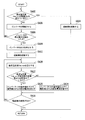
- FIG. 3 is a flowchart of processing related to braking control of the embodiment.
- the initial value of the DC voltage value Vdc_est is defined as 0.
- the series of processes shown in the figure is repeated at predetermined intervals.
- the braking control unit 74 determines whether or not the DC voltage value Vdc_est exceeds the threshold value Vth (step SA02).
- the DC voltage value Vdc_est was calculated in the previous processing cycle.
- the braking control unit 74 shuts off the circuit breaker 4 (step SA04), and ends a series of processes of this cycle.
- the braking control unit 74 causes the inverter 13 to function without interrupting the circuit breaker 4 (step SA06).
- the braking control unit 74 determines whether or not a stop command for the inverter 13 from the host device has been detected (step SA08). If the stop command of the inverter 13 is not detected from the host device, the braking control unit 74 advances the process to step SA02.
- the braking control unit 74 stops the output of the inverter 13 (step SA10). Subsequently, the braking control unit 74 shuts off the circuit breaker 4 (step SA12).
- the estimation unit 73 calculates the DC voltage value Vdc_est using the following equation (1) (step SA20).
- the DC voltage value Vdc_est is defined by the following equation (1).
- Vdc0 Reference voltage of DC part
- R Resistance value of DC part
- C DC part capacitor
- t Time Ir (t): Regenerative current flowing from the electric motor 3 to the inverter 13 at time t
- the above resistance value is the sum of the resistance values of the resistance 15 and the resistance 16.
- the above capacitor C has the capacity of the smoothing capacitor 14.
- the smoothing capacitor 14 is formed by a combination of a plurality of capacitors connected in parallel to each other, the above-mentioned capacitor C is the sum of the capacitances of the plurality of capacitors.
- the first term on the right side of the above equation (1) has the reference voltage Vcd0 of the DC part as the initial value, and the discharge characteristics according to the time constant RC defined by the resistance value R of the DC part and the capacitor C of the DC part.
- the second term defines the voltage change due to the charging of the capacitor C of the DC portion charged by the regenerative current Ir (t).
- the terminal voltage of the smoothing capacitor 14 can be controlled to be lower than the reference voltage Vcd0 of the DC portion, no overvoltage will occur in the DC portion. That is, the occurrence of the above overvoltage can be suppressed by adjusting the regenerative current Ir (t) so as to satisfy the following equation (2).
- the braking control unit 74 determines whether or not the DC voltage value Vdc_est derived by the calculation using the equation (1) exceeds the predetermined reference voltage Vdc0 of the DC unit (step SA22). This determination corresponds to a determination as to whether or not the condition of the above equation (2) is satisfied. As a result, the braking control unit 74 can indirectly detect the charging state of the smoothing capacitor 14.
- the integral value of Ir (t) in a predetermined period may be used for the calculation of the integral of the regenerative current Ir (t).
- the above-mentioned predetermined period may be in the range of a natural number multiple of the basic cycle of the AC output of the inverter 13.
- the braking control unit 74 raises the command value of the inverter 13 to control so as to increase the regenerative current from the electric motor 3 (step SA24). ..
- the braking control unit 74 increases the DC voltage value Vdc, which is estimated to have a margin until the overvoltage state is reached, so as not to exceed the reference voltage Vdc0, and increases the number from the motor 3 side to the inverter 13. It is possible to pass an electric current.
- the command value of the inverter 13 defines the amount of regeneration, and it is specified that the amount of regeneration increases by increasing the above-mentioned command value.
- the braking control unit 74 lowers the command value of the inverter 13 to control so as to reduce the regenerative current from the electric motor 3 (step SA26). ..
- the braking control unit 74 can reduce the current flowing from the motor 3 side to the inverter 13 so as to lower the DC voltage value Vdc estimated to be in the overvoltage state.
- the braking control unit 74 determines whether or not the speed of the electric motor 3 is zero (step SA28). If the speed of the electric motor 3 is not zero, the braking control unit 74 repeats the process from step SA20. If the speed of the electric motor 3 is zero, the braking control unit 74 ends a series of processes of this cycle. Instead of determining whether or not the speed of the electric motor 3 is zero, the speed of the electric motor 3 is determined using a threshold value near zero, and the electric motor 3 is lower than the speed defined by the threshold value. The speed of may be considered as zero.
- the estimation unit 73 calculates the DC voltage value Vdc_est based on the detected value (current value I) of the load current flowing between the inverter 13 and the electric motor 3. To do.
- the braking control unit 74 controls the inverter 13 so that the DC voltage value Vdc_est does not exceed the reference voltage Vdc0 during the period when the electric motor 3 is in the regenerative state. As a result, the electric motor 3 can be braked more quickly.
- the braking control unit 74 brakes the electric motor 3 by detecting a stop command of the inverter 13 from the host device by the above control, but the inverter 13 is prevented so that the DC voltage value Vdc_est does not exceed the reference voltage Vdc0 during the braking. To control. As a result, it is possible to suppress an overvoltage state due to braking control.
- the braking control unit 74 can cut off the electric power flowing from the AC power supply 2 through the diode converter 12 by opening the circuit breaker 4 at a desired timing related to the braking control of the electric motor 3. Thereby, for example, by opening the circuit breaker 4 during the period when the electric motor 3 is in the regenerative state, it is possible to control the DC voltage value Vdc_est so as not to exceed the reference voltage Vdc0.
- the estimation unit 73 may detect that the electric motor 3 is in the regenerative state based on the current value I detected by the current sensor AM. In that case, the estimation unit 73 can detect the inflow of regenerative energy from the electric motor 3 to the inverter 13 by detecting the inflow of active power from the electric motor 3 based on the current value I detected by the current sensor AM. it can.
- the braking control unit 74 may control the change in the DC Vdc based on the DC voltage value Vdc_est calculated by the estimation unit 73. In this case, the braking control unit 74 controls the inverter 13 so that the DC voltage value Vdc_est does not exceed the reference voltage Vdc0. At that time, the braking control unit 74 may control the inverter 13 so that more AC power from the electric motor 3 is supplied to the inverter 13 within a range in which the DC voltage value Vdc_est does not exceed the reference voltage Vdc0 on the DC side. .. As a result, the electric motor 3 can be braked more quickly while suppressing the DC voltage Vdc from becoming an overvoltage.
- the DC voltage value Vdc_est can be calculated based on the above equation (1) without providing a voltage detector for detecting the DC voltage Vdc on the DC side for each cell unit 6.
- the configuration of the conversion device 1 can be simplified.
- the sensor that collects the data for calculating the DC voltage value Vdc_est may be at least two current sensors AM.
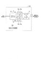
- the cell unit 6VI shown in FIG. 4 differs from the cell unit 6 shown in FIG. 2 in the following points.
- the cell unit 6VI further includes resistors 15P and 16P and switches 15S and 16S.
- the resistors 15P and 16P and the switches 15S and 16S are connected in series with each other.
- the resistors 15P and 16P connected in series and both ends of the switches 15S and 16S are connected to the smoothing capacitor 14 in parallel.
- one end of each of the switches 15S and 16S is connected to the resistors 15P and 16P connected in series and both ends of the switches 15S and 16S. It has become.
- the connection points of the resistors 15P and 16P are connected to the frame of the cell unit 6VI together with the connection points of the resistors 15 and 16.
- the cell unit control unit CUC generates a signal for controlling the switching element 13S constituting the diode converter 12 and the inverter 13 based on the gate pulse signal from the control device 7. Further, the cell unit control unit CUC generates a signal for controlling the switches 15S and 16S based on the control signal from the control device 7.
- the braking control unit 74 controls the above switches 15S and 16S in addition to controlling the circuit breaker 4 and the inverter 13.
- the braking control unit 74 may control the switches 15S and 16S in accordance with the timing of controlling the circuit breaker 4. For example, the braking control unit 74 may conduct the switches 15S and 16S when the circuit breaker 4 is cut off, and may cause the switches 15S and 16S to be cut off when the circuit breaker 4 is conducted.
- the switches 15S and 16S are controlled in a cutoff state by the braking control unit 74 in normal times, and the resistors 15P and 16P do not serve as a load for the diode converter 12.
- the switches 15S and 16S are controlled to a conductive state by the braking control unit 74 when the regenerative state of the electric motor 3 is detected.
- the switches 15S and 16S discharge the electric charge accumulated in the smoothing capacitor 14 through the resistors 15P and 16P.
- the resistance values R of the equations (1) and (2) are the combined resistance values R1 of the resistors 15 and 16 and the combined resistance of the resistors 15 and 16 as shown in the following equation (3).
- Value R2 is the value when connected in parallel.
- R R1xR2 / (R1 + R2) ⁇ ⁇ ⁇ (3)
- the power conversion device 1 includes a diode converter 12, an inverter 13, a smoothing capacitor 14, resistors 15 and 16, a current sensor AM, an estimation unit 73, and braking control.
- a unit 74 is provided.
- the diode converter 12 rectifies the alternating current from the alternating current power source 2.
- the DC side is connected to the DC output of the diode converter 12
- the AC side is connected to the load L
- the switching element 13S that converts the DC power on the DC side into AC power and the switching element 13S are connected in antiparallel. It is provided with a connection diode 13D.
- the smoothing capacitor 14 is provided at the DC output of the diode converter 12.
- the resistors 15 and 16 are connected in parallel to the smoothing capacitor 14.
- the current sensor AM detects the load current flowing between the inverter 13 and the electric motor 3.
- the estimation unit 73 calculates the DC voltage value Vdc_est based on the current value I detected by the current sensor AM.
- the braking control unit 74 controls the inverter 13 so that the DC voltage value Vdc_est does not exceed the reference voltage Vdc0 during the period when the electric motor 3 is in the regenerative state. As a result, the power conversion device 1 can brake the electric motor 3 more quickly.
Landscapes
- Engineering & Computer Science (AREA)
- Power Engineering (AREA)
- Inverter Devices (AREA)
- Stopping Of Electric Motors (AREA)
- Control Of Ac Motors In General (AREA)
Abstract
実施形態の一態様の電力変換装置は、ダイオードコンバータと、インバータと、平滑コンデンサと、抵抗と、電流センサと、推定部と、制御部とを備える。ダイオードコンバータは、電源からの交流を整流する。インバータは、直流側が前記ダイオードコンバータの直流出力に接続され、交流側が電動機に接続され、前記直流側の直流電力を交流電力に変換する半導体スイッチング素子と前記半導体スイッチング素子に逆並列に接続される逆接続ダイオードとを備える。平滑コンデンサは、前記ダイオードコンバータの直流出力に設けられる。抵抗は、前記平滑コンデンサに並列に接続される。電流センサは、前記インバータと前記電動機の間に流れる負荷電流を検出する。推定部は、前記電流センサによって検出された電流値Iに基づいて、前記直流側の直流電圧Vdcの推定値を算出する。制御部は、前記電動機が回生状態になっている期間に、前記直流側の直流電圧Vdcの推定値が所定の基準電圧を超えないように前記インバータを制御する。
Description
この発明は、電力変換装置及び電動機制動方法に関する。
電力変換装置は、直流電力から変換した交流電力を電動機に供給して、電動機と電動機の回転に連動する機械負荷とを駆動する。回転中の電動機と機械負荷とを制動すると、起電力による回生エネルギーが生じる。この回生エネルギーが電動機から電力変換装置に流入すると、電力変換装置の直流側の電圧(直流電圧)の上昇を招く。その際に直流電圧の過電圧状態が生じることを、放電回路を利用して回避する場合に、電動機を速やかに停止させることが困難になることがあった。
本発明が解決しようとする課題は、電動機をより速やかに制動させることが可能な電力変換装置及び電動機制動方法を提供することである。
実施形態の一態様の電力変換装置は、ダイオードコンバータと、インバータと、平滑コンデンサと、抵抗と、電流センサと、推定部と、制御部とを備える。ダイオードコンバータは、電源からの交流を整流する。インバータは、直流側が前記ダイオードコンバータの直流出力に接続され、交流側が電動機に接続され、前記直流側の直流電力を交流電力に変換する半導体スイッチング素子と前記半導体スイッチング素子に逆並列に接続される逆接続ダイオードとを備える。平滑コンデンサは、前記ダイオードコンバータの直流出力に設けられる。抵抗は、前記平滑コンデンサに並列に接続される。電流センサは、前記インバータと前記電動機の間に流れる負荷電流を検出する。推定部は、前記電流センサによって検出された電流値Iに基づいて、前記直流側の直流電圧Vdcの推定値を算出する。制御部は、前記電動機が回生状態になっている期間に、前記直流側の直流電圧Vdcの推定値が所定の基準電圧を超えないように前記インバータを制御する。
以下、実施形態の電力変換装置を、図面を参照して説明する。なお以下の説明では、同一又は類似の機能を有する構成に同一の符号を付す。そして、それら構成の重複する説明は省略する場合がある。なお以下で参照する図面は、説明の便宜上、制御用のゲート配線などの図示が省略されている場合がある。
ここで、「正極P」と「負極N」について先に定義する。「正極P」とは、電力変換装置1が動作している場合に、正電位となる部位を意味する。「負極N」とは、電力変換装置1が動作している場合に、負電位となる部位を意味する。
なお、電力変換装置1における直流リンクの基準電圧Vdc0が所定の電圧として規定されている。基準電圧Vdc0は、例えば、正極Pと負極N間の電圧である。この基準電圧Vdc0は、直流(直流リンク)の定格電圧と呼ばれることがある。
図1から図3を参照して、実施形態の電力変換装置1について説明する。
電力変換装置1は、交流電源2から供給される交流電力を直流電力に変換し、変換した直流電力を所望の周波数・電圧の交流電力に変換して電動機3に供給する。電動機3は、例えば、3相型の誘導電動機であるが、これに限定されない。
電力変換装置1の電源側は、遮断器4を介して交流電源2に接続されている。遮断器4は、交流電源2(電源)から供給される電力を、後述する制御装置7の制御に基づいて遮断する。なお、遮断器4は、図1に示すように電力変換装置1と別体で構成されていてもよく、電力変換装置1の一部として構成されていてもよい。
本実施形態では、電力変換装置1が複数のセルユニット6sを備える例について説明する。なお、電力変換装置1は、複数のセルユニット6sに代えて、3相コンバータおよび3相インバータを備えてもよい。
電力変換装置1は、交流電源2から供給される交流電力を直流電力に変換し、変換した直流電力を所望の周波数・電圧の交流電力に変換して電動機3に供給する。電動機3は、例えば、3相型の誘導電動機であるが、これに限定されない。
電力変換装置1の電源側は、遮断器4を介して交流電源2に接続されている。遮断器4は、交流電源2(電源)から供給される電力を、後述する制御装置7の制御に基づいて遮断する。なお、遮断器4は、図1に示すように電力変換装置1と別体で構成されていてもよく、電力変換装置1の一部として構成されていてもよい。
本実施形態では、電力変換装置1が複数のセルユニット6sを備える例について説明する。なお、電力変換装置1は、複数のセルユニット6sに代えて、3相コンバータおよび3相インバータを備えてもよい。
まず、電力変換装置1の電気的な全体構成について説明する。図1は、実施形態の電力変換装置1の一例を示す図である。図1では、電気回路系統を単線で示すとともに、開閉器などの図示を省略している。電力変換装置1は、例えば、入力変圧器5と、複数のセルユニット6sと、制御装置7と、電流センサAMとを備えている。
入力変圧器5には、交流電源2から交流電力が供給される。入力変圧器5は、交流電源2から供給された交流電力の電圧(1次側電圧)を所望の2次側電圧に変圧するとともに、2次側電圧の交流電力を複数のセルユニット6sのそれぞれに供給する。入力変圧器5は、1次巻線と、互いに絶縁された複数群の巻き線(2次巻線)とを有する。1次巻線と2次巻線との間も絶縁されている。
複数のセルユニット6sは、例えば、3台の負荷第1相のセルユニット6A1、6A2、6A3(図中の記載はU1、U2、U3。)、3台の負荷第2相のセルユニット6B1、6B1(図中の記載はV1、V2、V3。)、6B3および3台の負荷第3相のセルユニット6C1、6C2、6C3(図中の記載はW1、W2、W3。)を含む。セルユニット6A1、6A2、6A3、6B1、6B1、6B3、6C1、6C2、6C3は、同一の回路構成を有し、これらを区別することなく説明する場合には、単にセルユニット6と呼ぶ。各セルユニット6は、入力変圧器5の2次巻線から供給されたそれぞれ3相の交流電力を直流電力に変換し、変換した直流電力を所望の周波数・電圧の交流電力に変換して出力する。
例えば、入力変圧器5の2次側第1群はセルユニット6A1の入力に接続されている。入力変圧器5の2次側第2群はセルユニットV1の入力に接続されている。入力変圧器5の2次側第3群はセルユニットW1の入力に接続されている。入力変圧器5の2次側第4群はセルユニット6A2の入力に接続されている。入力変圧器5の2次側第5群はセルユニット6B2の入力に接続されている。入力変圧器5の2次側第6群はセルユニット6C2の入力に接続されている。入力変圧器5の2次側第7群はセルユニット6A3の入力に接続されている。入力変圧器5の2次側第8群はセルユニット6B3の入力に接続されている。入力変圧器5の2次側第9群はセルユニット6C3の入力に接続されている。
本実施形態では、セルユニット6A1、6A2、6A3は、表記の順番で、出力が互いに電気的に直列に接続されている。セルユニット6A3のセルユニット6A2と接続されない出力端子は、電動機3の第1相(U相)に接続されている。セルユニット6A1のセルユニット6A2と接続されない出力端子は中性点に接続される。本実施形態では、セルユニット6B1、6B2、6B3は、表記の順番で、出力が互いに電気的に直列に接続されている。セルユニット6B3のセルユニット6B2と接続されない出力端子は、電動機3の第2相(V相)に接続されている。セルユニット6B1のセルユニット6B2と接続されない出力端子は中性点に接続される。本実施形態では、セルユニット6C1、6B2、6B3は、表記の順番で、出力が互いに電気的に直列に接続されている。セルユニット6C3のセルユニット6C2と接続されない出力端子は、電動機3の第3相(W相)に接続されている。セルユニット6C1のセルユニット6C2と接続されない出力端子は中性点に接続される。これにより、電力変換装置1は、大容量の交流電力を電動機3に供給可能である。
電流センサAM1と電流センサAM2は、電力変換装置1のインバータ13(図2)と電動機3の間に流れる負荷電流(相電流)を検出する。例えば、電流センサAM1が交流出力の第1相に、電流センサAM2が交流出力の第3相に設けられている。交流出力の第2相の電流は電流センサAM1と電流センサAM2の値から求めることができるので省略することができる。なお、電流センサAM1と電流センサAM2とを互いに区別しない場合には、単に電流センサAMと記すことがある。電流センサAMによって検出された電流値を電流Iと呼ぶことがある。
制御装置7は、各セルユニット6を制御する、又は保護する。制御装置7は、例えば、記憶部71と、稼働制御部72と、推定部73と、制動制御部74と、を備える。
記憶部71は、複数のセルユニット6sの制御に関わる各種データを格納する。各種データには、例えば、セルユニット6の直流電圧の過電圧を制限するための制限値(閾値Vth)、セルユニット6の直流電圧の基準電圧Vdc0、電流センサAMによって検出された電流値Iの履歴データとその積算値データ、セルユニット6の直流電圧値Vdcの推定値(以下、直流電圧値Vdc_estと呼ぶ。)などが含まれる。閾値Vthは、例えば、直流リンクの直流電圧の上限値として規定される。基準電圧Vdc0は、制御目標電圧の一例である。
稼働制御部72は、記憶部71に格納されているデータ、例えば直流電圧値Vdc_estを示す情報および、電流センサAMにより検出された電流Iを示す情報に基づき、各セルユニット6に含まれるスイッチング素子13S(図2)を制御するための制御信号を生成する。稼働制御部72は、生成した制御信号を各セルユニット6に送ることで、各セルユニット6を制御する。稼働制御部72は、電動機3の制御状態を示す信号(例えば、回転数のフィードバック信号)を取得し、当該フィードバック信号に基づいて、各セルユニット6を制御する。また、制御装置7は、他の装置から電動機3の制御指令信号を取得し、当該制御指令信号に基づいて、各セルユニット6を制御する。
推定部73は、電流センサAMによって検出された電流値Iに基づいて、直流電圧値Vdc_estを算出する。直流電圧値Vdc_estの算出については後述する。
制動制御部74は、直流電圧値Vdc_estに基づいて、直流電圧Vdcが基準電圧Vdc0を超えないように調整しながら、電動機3を制動させるように各部を制御する。例えば、制動制御部74は、電動機3の制動制御に係る所望のタイミングで遮断器4を開放させる。この所望のタイミングは、電動機3が回生状態になったときに整合させるとよい。
さらに、制動制御部74は、電動機3が回生状態になっている期間に、電動機3からの交流電力がより多くインバータ13に供給されるようにインバータ13を制御する。その際に、制動制御部74は、直流電圧値Vdc_estが直流側の基準電圧Vdc0を超えないように調整する。遮断器4とインバータ13の制御の詳細について後述する。
次に、セルユニット6について説明する。
図2は、実施形態のセルユニット6を示す図である。セルユニット6は、例えば、ダイオードコンバータ12と、インバータ13と、平滑コンデンサ14と、抵抗15、16と、セルユニット制御部CUCとを含む。ダイオードコンバータ12の直流出力とインバータ13の直流入力は、直流リンクを介して、互いに正極(P)同士、および負極(N)極同士が電気的に接続される。平滑コンデンサ14は、直流リンクに設けられていて、平滑コンデンサ14の端子が直流リンクの正極と負極に電気的に接続されている。
図2は、実施形態のセルユニット6を示す図である。セルユニット6は、例えば、ダイオードコンバータ12と、インバータ13と、平滑コンデンサ14と、抵抗15、16と、セルユニット制御部CUCとを含む。ダイオードコンバータ12の直流出力とインバータ13の直流入力は、直流リンクを介して、互いに正極(P)同士、および負極(N)極同士が電気的に接続される。平滑コンデンサ14は、直流リンクに設けられていて、平滑コンデンサ14の端子が直流リンクの正極と負極に電気的に接続されている。
以下の説明では、セルユニット6A1を例示して、外部との接続関係を示しながらその一例について説明する。他のセルユニット6についても同様である。
ダイオードコンバータ12は、3相交流入力型の順変換器であり、その入力部が入力変圧器5の二次側の一つの群に電気的に接続されている。ダイオードコンバータ12は、交流を整流することで、入力変圧器5から入力された交流電力を直流電力に変換する。平滑コンデンサ14は、変換後の直流電圧を平滑化する。
インバータ13は、単相交流出力型の逆変換器である。インバータ13は、例えば、直流側の直流電力を交流電力に変換するスイッチング素子13Sとスイッチング素子13Sに逆並列に接続される逆接続ダイオード13Dとを備える。スイッチング素子13Sは、半導体スイッチング素子の一例である。インバータ13は、直流側がダイオードコンバータ12の直流出力に接続され、交流側が電動機3又は他のセルユニット6の出力と直列になるように接続されている。インバータ13は、例えば、変換後の交流電力を電動機3の第1相に出力する。
抵抗15、16は、互いに直列に接続され、直列に接続された両端が平滑コンデンサ14に並列になるように接続されている。抵抗15、16の接続点は、セルユニット6のフレームに接続される。抵抗15、16は、平滑コンデンサ14に蓄積された電荷を放電させる。
セルユニット制御部CUCは、制御装置7からのゲートパルス信号に基づいて、ダイオードコンバータ12およびインバータ13を構成するスイッチング素子を制御する信号を生成する。制御装置7からのゲートパルス信号はセルユニット制御部CUC経由でダイオードコンバータ12およびインバータ13を構成するスイッチング素子に与えられる。
図3は、実施形態の制動制御に係る処理のフローチャートである。
例えば、直流電圧値Vdc_estの初期値を0と定義する。図に示す一連の処理は、所定の間隔で繰り返して実施される。
例えば、直流電圧値Vdc_estの初期値を0と定義する。図に示す一連の処理は、所定の間隔で繰り返して実施される。
まず、制動制御部74は、直流電圧値Vdc_estが閾値Vthを超えているか否かを判定する(ステップSA02)。なお、直流電圧値Vdc_estは、前回の処理サイクルの中で算出されたものである。
直流電圧値Vdc_estが閾値Vthを超えている場合には、制動制御部74は、遮断器4を遮断して(ステップSA04)、今回サイクルの一連の処理を終える。
直流電圧値Vdc_estが閾値Vthを超えていない場合には、制動制御部74は、遮断器4を遮断することなくインバータ13を機能させる(ステップSA06)。
次に、制動制御部74は、上位装置からのインバータ13の停止指令を検出したか否かを判定する(ステップSA08)。上位装置からのインバータ13の停止指令を検出しなければ、制動制御部74は、処理をステップSA02に進める。
上位装置からのインバータ13の停止指令を検出すると、制動制御部74は、インバータ13の出力を停止する(ステップSA10)。続けて、制動制御部74は、遮断器4を遮断する(ステップSA12)。
次に、推定部73は、次に示す式(1)を用いて直流電圧値Vdc_estを算出する(ステップSA20)。例えば、直流電圧値Vdc_estは、下記の式(1)で定義される。

式(1)における各変数は、下記のとおりである。
Vdc0: 直流部の基準電圧
R: 直流部の抵抗値
C: 直流部のキャパシタ
t: 時刻
Ir(t): 時刻tにおいて、電動機3からインバータ13に流入する回生電流
Vdc0: 直流部の基準電圧
R: 直流部の抵抗値
C: 直流部のキャパシタ
t: 時刻
Ir(t): 時刻tにおいて、電動機3からインバータ13に流入する回生電流
実施形態のセルユニット6の場合、上記の抵抗値は、抵抗15と抵抗16の抵抗値の和になる。上記のキャパシタCは、平滑コンデンサ14の容量になる。なお、平滑コンデンサ14が互いに並列に接続された複数のコンデンサの組み合わせで形成されている場合には、上記のキャパシタCは、複数のコンデンサの容量の和になる。
上記の式(1)の右辺の第1項は、直流部の基準電圧Vcd0を初期値とし、直流部の抵抗値Rと直流部のキャパシタCとにより規定される時定数RCに従った放電特性を規定する。同第2項は、回生電流Ir(t)によって充電される直流部のキャパシタCの充電による電圧変化を規定する。上記の第1項と第2項を加算することにより、キャパシタCに掛かる電圧、つまり平滑コンデンサ14の端子電圧(直流リンクの直流電圧)が導出される。
平滑コンデンサ14の端子電圧が直流部の基準電圧Vcd0を下回るように制御できれば直流部に過電圧は生じない。つまり、下記の式(2)を満たすように、回生電流Ir(t)を調整することで、上記の過電圧の発生を抑制できる。

上記のとおり、式(2)の右辺は、上記の式(1)の右辺と同じである。そこで、制動制御部74は、式(1)を用いた演算により導かれた直流電圧値Vdc_estが、予め定められた直流部の基準電圧Vdc0を超えているか否かを判定する(ステップSA22)。この判定は、上記の式(2)の条件を満たしているか否かの判定に相当する。これにより、制動制御部74は、平滑コンデンサ14の充電状態を間接的に検出することができる。なお、回生電流Ir(t)の積分の演算は、所定期間のIr(t)の積算値を用いてもよい。例えば、上記の所定期間は、インバータ13の交流出力の基本周期の自然数倍の範囲にするとよい。
直流電圧値Vdc_estが直流部の基準電圧Vdc0を超えていない場合には、制動制御部74は、インバータ13の指令値を上げて、電動機3からの回生電流を増やすように制御する(ステップSA24)。これにより、制動制御部74は、過電圧状態になるまで余裕があると推定された直流電圧値Vdcを、基準電圧Vdc0を超えないように高めることと、電動機3側からインバータ13に、より多くの電流を流すこととができる。なお、上記のインバータ13の指令値とは、回生量を規定するものであり、上記の指令値を上げることにより回生量が増えるように規定される。
直流電圧値Vdc_estが設定値(閾値)Vdc0を超えている場合には、制動制御部74は、インバータ13の指令値を下げて、電動機3からの回生電流を減らすように制御する(ステップSA26)。これにより、制動制御部74は、過電圧状態にあると推定された直流電圧値Vdcを下げるように、電動機3側からインバータ13に流れる電流を減らすことができる。
SA24又はSA26の処理を終えると、制動制御部74は、電動機3の速度がゼロか否かを判定する(ステップSA28)。制動制御部74は、電動機3の速度がゼロでなければ、ステップSA20からの処理を繰り返す。制動制御部74は、電動機3の速度がゼロであれば、今回サイクルの一連の処理を終える。なお、上記の電動機3の速度がゼロか否かを判定することに代えて、ゼロ近傍の閾値を用いて電動機3の速度を判定して、閾値で規定される速度より低下した場合の電動機3の速度をゼロとみなすようにしてもよい。
上記の実施形態によれば、電動機3を制動させる際に、推定部73は、インバータ13と電動機3の間に流れる負荷電流の検出値(電流値I)に基づいて、直流電圧値Vdc_estを算出する。制動制御部74は、電動機3が回生状態になっている期間に、直流電圧値Vdc_estが基準電圧Vdc0を超えないようにインバータ13を制御する。これにより、電動機3をより速やかに制動させることができる。
制動制御部74は、上記の制御により、上位装置からのインバータ13の停止指令を検出して電動機3を制動させるが、その制動中に直流電圧値Vdc_estが基準電圧Vdc0を超えないようにインバータ13を制御する。これにより、制動制御によって過電圧状態になることを抑制することができる。
制動制御部74は、電動機3の制動制御に係る所望のタイミングで遮断器4を開放させることにより、交流電源2からダイオードコンバータ12を経て流入する電力を遮断することができる。これにより、例えば電動機3が回生状態になっている期間に、遮断器4を開放させることで、直流電圧値Vdc_estが基準電圧Vdc0を超えないように制御することができる。
なお、推定部73は、電動機3が回生状態になっていることを、電流センサAMによって検出された電流値Iに基づいて検出するとよい。その場合、推定部73は、電流センサAMによって検出された電流値Iに基づいて、電動機3から有効電力の流入を検出することで、電動機3からインバータ13に回生エネルギーの流入を検出することができる。
制動制御部74は、推定部73によって算出された直流電圧値Vdc_estに基づいて、直流Vdcの変化を制御してもよい。この場合、制動制御部74は、直流電圧値Vdc_estが基準電圧Vdc0を超えないようにインバータ13を制御する。その際に、制動制御部74は、直流電圧値Vdc_estが直流側の基準電圧Vdc0を超えない範囲で、電動機3からの交流電力がより多くインバータ13に供給されるようにインバータ13を制御するとよい。これにより、直流電圧Vdcが過電圧になることを抑制しつつ、電動機3をより速やかに制動させることができる。
上記の実施形態では、直流側の直流電圧Vdcを検出する電圧検出器をセルユニット6ごとに設けることなく、直流電圧値Vdc_estを上記の式(1)に基づいて算出することができるため、電力変換装置1の構成を簡素化できる。例えば、直流電圧値Vdc_estを算出のためのデータを収集するセンサは、少なくとも2個の電流センサAMでよい。
(第2の実施形態)
図1と図4を参照して、第2の実施形態について説明する。第1の実施形態では、抵抗15、16の値が固定値である事例について説明した。本実施形態では、式(1)と式(2)の抵抗値Rを、系の状態により調整する事例について説明する。
図1と図4を参照して、第2の実施形態について説明する。第1の実施形態では、抵抗15、16の値が固定値である事例について説明した。本実施形態では、式(1)と式(2)の抵抗値Rを、系の状態により調整する事例について説明する。
図4に示すセルユニット6VIは、図2に示したセルユニット6と比べて下記の点が異なる。セルユニット6VIは、抵抗15P、16Pと、スイッチ15S、16Sとをさらに備える。
抵抗15P、16Pと、スイッチ15S、16Sは、互いに直列に接続される。直列に接続された抵抗15P、16Pと、スイッチ15S、16Sの両端は、平滑コンデンサ14に並列になるように接続されている。例えば、スイッチ15S、抵抗15P、16P、スイッチ16Sの順に直列に接続されている場合、スイッチ15S、16Sの夫々の一端が、直列に接続された抵抗15P、16Pと、スイッチ15S、16Sの両端になっている。この場合、抵抗15P、16Pの接続点は、抵抗15、16の接続点とともにセルユニット6VIのフレームに接続される。
セルユニット制御部CUCは、制御装置7からのゲートパルス信号に基づいて、ダイオードコンバータ12およびインバータ13を構成するスイッチング素子13Sを制御するための信号を生成する。さらに、セルユニット制御部CUCは、制御装置7からの制御信号に基づいて、スイッチ15S、16Sを制御するための信号を生成する。
なお、制動制御部74は、遮断器4とインバータ13の制御に加えて、上記のスイッチ15S、16Sを制御する。制動制御部74は、遮断器4を制御するタイミングに合わせて、上記のスイッチ15S、16Sを制御するとよい。例えば、制動制御部74は、遮断器4を遮断するときに、上記のスイッチ15S、16Sを導通させて、遮断器4を導通させるときに、上記のスイッチ15S、16Sを遮断させるとよい。
例えば、スイッチ15S、16Sは、平時には制動制御部74によって遮断状態に制御されていて、抵抗15P、16Pがダイオードコンバータ12の負荷にならない。スイッチ15S、16Sは、電動機3の回生状態が検出されたときに制動制御部74によって導通状態に制御される。これにより、スイッチ15S、16Sは、抵抗15P、16Pを経て平滑コンデンサ14に蓄積された電荷を放電させる。
上記のように制御すると、回生状態のときの放電量が増加する。具体的には、式(1)と式(2)の抵抗値Rが、次の式(3)に示すように、抵抗15、16の合成抵抗の値R1と、抵抗15、16の合成抵抗の値R2とを並列接続にした場合の値になる。
R=R1xR2 / (R1+R2) ・・・(3)
R=R1xR2 / (R1+R2) ・・・(3)
上記の実施形態によれば、第1の実施形態と同様の効果を奏することのほか、回生状態になっているときの電力損失量を増大させることができ、平滑コンデンサ14に蓄積された電荷をより効率よく放電させることができる。
以上説明した少なくとも一つの実施形態によれば、電力変換装置1は、ダイオードコンバータ12と、インバータ13と、平滑コンデンサ14と、抵抗15、16と、電流センサAMと、推定部73と、制動制御部74とを備える。ダイオードコンバータ12は、交流電源2からの交流を整流する。インバータ13は、直流側がダイオードコンバータ12の直流出力に接続され、交流側が負荷Lに接続され、直流側の直流電力を交流電力に変換するスイッチング素子13Sとスイッチング素子13Sに逆並列に接続される逆接続ダイオード13Dとを備える。平滑コンデンサ14は、ダイオードコンバータ12の直流出力に設けられる。抵抗15、16は、平滑コンデンサ14に並列に接続される。電流センサAMは、インバータ13と電動機3の間に流れる負荷電流を検出する。推定部73は、電流センサAMによって検出された電流値Iに基づいて、直流電圧値Vdc_estを算出する。制動制御部74は、電動機3が回生状態になっている期間に、直流電圧値Vdc_estが基準電圧Vdc0を超えないようにインバータ13を制御する。これにより、電力変換装置1は、電動機3をより速やかに制動させることができる。
本発明のいくつかの実施形態を説明したが、これらの実施形態は、例として提示したものであり、発明の範囲を限定することは意図していない。これら実施形態は、その他の様々な形態で実施されることが可能であり、発明の要旨を逸脱しない範囲で、種々の省略、置き換え、変更を行うことができる。これら実施形態やその変形は、発明の範囲や要旨に含まれると同様に、特許請求の範囲に記載された発明とその均等の範囲に含まれるものである。
1…電力変換装置、2…交流電源、3…電動機、4…遮断器、5…入力変圧器、6…セルユニット、6s…複数のセルユニット、7…制御装置、12…ダイオードコンバータ、13…インバータ、13S…スイッチング素子、13D…逆接続ダイオード、14…平滑コンデンサ、15、15P、16、16P…抵抗、15S、16S…スイッチ、CUC…セルユニット制御部、71…記憶部、72…稼働制御部、73…推定部、74…制動制御部、AM、AM1、AM2…電流センサ
Claims (7)
- 電源からの交流を整流するダイオードコンバータと、
直流側が前記ダイオードコンバータの直流出力に接続され、交流側が電動機に接続され、前記直流側の直流電力を交流電力に変換する半導体スイッチング素子と前記半導体スイッチング素子に逆並列に接続される逆接続ダイオードとを備えるインバータと、
前記ダイオードコンバータの直流出力に設けられた平滑コンデンサと、
前記平滑コンデンサに並列に接続される抵抗と、
前記インバータと前記電動機の間に流れる負荷電流を検出する電流センサと、
前記電流センサによって検出された電流値Iに基づいて、前記直流側の直流電圧Vdcの推定値を算出する推定部と、
前記電動機が回生状態になっている期間に、前記直流側の直流電圧Vdcの推定値が所定の基準電圧を超えないように前記インバータを制御する制御部と
を備える電力変換装置。 - 前記電源から前記ダイオードコンバータに供給される電力を、前記制御部の制御に基づいて遮断する遮断器
を備え、
前記制御部は、
前記電動機の制動制御に係る所望のタイミングで前記遮断器を開放させる、
請求項1に記載の電力変換装置。 - 前記推定部は、
前記電流センサによって検出された電流値Iに基づいて前記電動機から前記インバータに回生エネルギーの流入を検出し、
前記制御部は、
前記回生エネルギーの流入が検出されると前記遮断器を開放させる、
請求項2に記載の電力変換装置。 - 前記推定部は、
少なくとも前記直流側の基準電圧と、前記電流センサによって検出された前記電動機から前記インバータに流れる電流の電流値Iと、前記平滑コンデンサの容量Cとに基づいて、前記直流側の直流電圧Vdcの推定値を算出し、
前記制御部は、
前記算出された直流側の直流電圧Vdcの推定値に基づいて、前記直流電圧Vdcの変化を制御する、
請求項1に記載の電力変換装置。 - 前記推定部は、
前記直流側の基準電圧と、前記電流センサによって検出された前記電動機から前記インバータに流れる電流の電流値Iと、前記平滑コンデンサの容量Cと、前記平滑コンデンサの容量Cと前記抵抗の抵抗値Rとに基づいて規定される時定数RCとに基づいて、前記直流側の直流電圧Vdcの推定値を算出し、
前記制御部は、
前記算出された直流側の直流電圧Vdcの推定値に基づいて、前記直流電圧Vdcの変化を制御する、
請求項4に記載の電力変換装置。 - 前記制御部は、
前記直流側の直流電圧Vdcの推定値が前記直流側の基準電圧を超えない範囲で、前記電動機からの交流電力がより多く前記インバータに供給されるように前記インバータを制御する、
請求項1に記載の電力変換装置。 - 電源からの交流を整流するダイオードコンバータと、
直流側が前記ダイオードコンバータの直流出力に接続され、交流側が電動機に接続され、前記直流側の直流電力を交流電力に変換する半導体スイッチング素子と前記半導体スイッチング素子に逆並列に接続される逆接続ダイオードとを備えるインバータと、
前記ダイオードコンバータの直流出力に設けられた平滑コンデンサと、
前記平滑コンデンサに並列に接続される抵抗と、
前記インバータと前記電動機の間に流れる負荷電流を検出する電流センサと、
を備える電力変換装置による電動機制御方法であって、
前記電流センサによって検出された電流値Iに基づいて、前記直流側の直流電圧Vdcの推定値を算出するステップと、
前記電動機が回生状態になっている期間に、前記直流側の直流電圧Vdcの推定値が所定の基準電圧を超えないように前記インバータを制御するステップと
を含む電動機制動方法。
Priority Applications (4)
| Application Number | Priority Date | Filing Date | Title |
|---|---|---|---|
| CN201980019882.7A CN112470388B (zh) | 2019-06-14 | 2019-06-14 | 电力变换装置及电动机制动方法 |
| JP2020549711A JP7004838B2 (ja) | 2019-06-14 | 2019-06-14 | 電力変換装置及び電動機制動方法 |
| PCT/JP2019/023697 WO2020250429A1 (ja) | 2019-06-14 | 2019-06-14 | 電力変換装置及び電動機制動方法 |
| US17/310,302 US11949341B2 (en) | 2019-06-14 | 2019-06-14 | Power converter and electric motor braking method |
Applications Claiming Priority (1)
| Application Number | Priority Date | Filing Date | Title |
|---|---|---|---|
| PCT/JP2019/023697 WO2020250429A1 (ja) | 2019-06-14 | 2019-06-14 | 電力変換装置及び電動機制動方法 |
Publications (1)
| Publication Number | Publication Date |
|---|---|
| WO2020250429A1 true WO2020250429A1 (ja) | 2020-12-17 |
Family
ID=73780787
Family Applications (1)
| Application Number | Title | Priority Date | Filing Date |
|---|---|---|---|
| PCT/JP2019/023697 Ceased WO2020250429A1 (ja) | 2019-06-14 | 2019-06-14 | 電力変換装置及び電動機制動方法 |
Country Status (4)
| Country | Link |
|---|---|
| US (1) | US11949341B2 (ja) |
| JP (1) | JP7004838B2 (ja) |
| CN (1) | CN112470388B (ja) |
| WO (1) | WO2020250429A1 (ja) |
Citations (6)
| Publication number | Priority date | Publication date | Assignee | Title |
|---|---|---|---|---|
| JPH0819266A (ja) * | 1994-06-30 | 1996-01-19 | Shimadzu Corp | インバータ装置 |
| JP2002171695A (ja) * | 2000-12-06 | 2002-06-14 | Meidensha Corp | モータ駆動システム |
| JP2002233180A (ja) * | 2001-01-31 | 2002-08-16 | Toshiba Corp | 電力変換装置 |
| JP2012010488A (ja) * | 2010-06-25 | 2012-01-12 | Hitachi Ltd | 電動機システム,電力変換装置および電力変換装置の制御方法 |
| JP2012205391A (ja) * | 2011-03-25 | 2012-10-22 | Toshiba Schneider Inverter Corp | インバータ装置及び平滑コンデンサの容量推定方法 |
| WO2014141527A1 (ja) * | 2013-03-12 | 2014-09-18 | 三菱電機株式会社 | モータ制御装置 |
Family Cites Families (9)
| Publication number | Priority date | Publication date | Assignee | Title |
|---|---|---|---|---|
| JPH09255246A (ja) | 1996-03-19 | 1997-09-30 | Mitsubishi Electric Corp | 回生電力制御装置 |
| JP4634817B2 (ja) * | 2005-02-22 | 2011-02-16 | 株式会社Ihi | 負荷駆動装置 |
| JP4538359B2 (ja) | 2005-03-31 | 2010-09-08 | 株式会社日立産機システム | 電気回路モジュール |
| JP5260090B2 (ja) * | 2008-03-10 | 2013-08-14 | 株式会社日立産機システム | 電力変換装置 |
| JP4941595B2 (ja) * | 2009-02-09 | 2012-05-30 | トヨタ自動車株式会社 | 電源システム |
| JP5511515B2 (ja) | 2010-05-31 | 2014-06-04 | 株式会社日立製作所 | 電力変換装置 |
| JP5910155B2 (ja) * | 2012-02-22 | 2016-04-27 | 株式会社明電舎 | 電力変換装置の電圧制御装置 |
| US8981686B2 (en) * | 2013-01-24 | 2015-03-17 | Regal Beloit America, Inc. | Methods and systems for controlling an electric motor |
| JP6334367B2 (ja) * | 2014-11-07 | 2018-05-30 | 日立オートモティブシステムズ株式会社 | インバータ制御装置 |
-
2019
- 2019-06-14 WO PCT/JP2019/023697 patent/WO2020250429A1/ja not_active Ceased
- 2019-06-14 JP JP2020549711A patent/JP7004838B2/ja active Active
- 2019-06-14 US US17/310,302 patent/US11949341B2/en active Active
- 2019-06-14 CN CN201980019882.7A patent/CN112470388B/zh active Active
Patent Citations (6)
| Publication number | Priority date | Publication date | Assignee | Title |
|---|---|---|---|---|
| JPH0819266A (ja) * | 1994-06-30 | 1996-01-19 | Shimadzu Corp | インバータ装置 |
| JP2002171695A (ja) * | 2000-12-06 | 2002-06-14 | Meidensha Corp | モータ駆動システム |
| JP2002233180A (ja) * | 2001-01-31 | 2002-08-16 | Toshiba Corp | 電力変換装置 |
| JP2012010488A (ja) * | 2010-06-25 | 2012-01-12 | Hitachi Ltd | 電動機システム,電力変換装置および電力変換装置の制御方法 |
| JP2012205391A (ja) * | 2011-03-25 | 2012-10-22 | Toshiba Schneider Inverter Corp | インバータ装置及び平滑コンデンサの容量推定方法 |
| WO2014141527A1 (ja) * | 2013-03-12 | 2014-09-18 | 三菱電機株式会社 | モータ制御装置 |
Also Published As
| Publication number | Publication date |
|---|---|
| US20220321021A1 (en) | 2022-10-06 |
| JP7004838B2 (ja) | 2022-01-21 |
| JPWO2020250429A1 (ja) | 2021-09-13 |
| US11949341B2 (en) | 2024-04-02 |
| CN112470388B (zh) | 2023-09-01 |
| CN112470388A (zh) | 2021-03-09 |
Similar Documents
| Publication | Publication Date | Title |
|---|---|---|
| US10611245B2 (en) | Power conversion system | |
| US10525838B2 (en) | Power conversion system | |
| WO2016147413A1 (ja) | コンバータユニットシステム及びコンバータユニット | |
| JP2017118806A (ja) | 電力変換装置および制御方法 | |
| JP4859932B2 (ja) | 瞬時電圧低下・停電対策機能を有する電力変換システムの制御装置および制御方法 | |
| KR102586729B1 (ko) | 차량측 전기 에너지 저장소용 충전 회로 | |
| JP6786268B2 (ja) | 蓄電システム | |
| CN119968765A (zh) | 充电器和用于操作充电器的方法 | |
| CN107302332B (zh) | 抑制dc链路电容器的电压变动的电动机驱动装置 | |
| JP7004838B2 (ja) | 電力変換装置及び電動機制動方法 | |
| JP4044533B2 (ja) | 切換装置 | |
| JP2839638B2 (ja) | エレベータの制御装置 | |
| WO2011013187A1 (ja) | 自励式無効電力補償装置 | |
| KR102777642B1 (ko) | 인버터의 출력 개폐 또는 결상 상황에서의 보호 동작 방법 및 이를 이용하는 인버터 | |
| JPH1198610A (ja) | 交流電気車制御装置 | |
| JP2005019133A (ja) | ヒューズ溶断検出装置 | |
| US20250226760A1 (en) | Electrical power system | |
| WO2019039410A1 (ja) | 3端子静止形直流変圧器の制御装置 | |
| JPS62250876A (ja) | 電圧形インバ−タ装置 | |
| JPH073802Y2 (ja) | 共振形アクティブフィルタ | |
| KR20000004448U (ko) | 전력제어 시스템의 정류 회로 | |
| KR20240140297A (ko) | 인버터의 직류 링크 커패시터에 대한 용량 추정 방법 및 이를 이용하는 인버터 | |
| JPH11252923A (ja) | スイッチングコンバータ | |
| JPS6352667A (ja) | 補助電源装置 | |
| JP2001286154A (ja) | 電力変換装置 |
Legal Events
| Date | Code | Title | Description |
|---|---|---|---|
| ENP | Entry into the national phase |
Ref document number: 2020549711 Country of ref document: JP Kind code of ref document: A |
|
| 121 | Ep: the epo has been informed by wipo that ep was designated in this application |
Ref document number: 19932544 Country of ref document: EP Kind code of ref document: A1 |
|
| NENP | Non-entry into the national phase |
Ref country code: DE |
|
| 122 | Ep: pct application non-entry in european phase |
Ref document number: 19932544 Country of ref document: EP Kind code of ref document: A1 |