WO2020245934A1 - 遠心圧縮機のスクロール構造及び遠心圧縮機 - Google Patents
遠心圧縮機のスクロール構造及び遠心圧縮機 Download PDFInfo
- Publication number
- WO2020245934A1 WO2020245934A1 PCT/JP2019/022292 JP2019022292W WO2020245934A1 WO 2020245934 A1 WO2020245934 A1 WO 2020245934A1 JP 2019022292 W JP2019022292 W JP 2019022292W WO 2020245934 A1 WO2020245934 A1 WO 2020245934A1
- Authority
- WO
- WIPO (PCT)
- Prior art keywords
- flow path
- scroll
- centrifugal compressor
- scroll flow
- tongue
- Prior art date
- Legal status (The legal status is an assumption and is not a legal conclusion. Google has not performed a legal analysis and makes no representation as to the accuracy of the status listed.)
- Ceased
Links
Images




Classifications
-
- F—MECHANICAL ENGINEERING; LIGHTING; HEATING; WEAPONS; BLASTING
- F04—POSITIVE - DISPLACEMENT MACHINES FOR LIQUIDS; PUMPS FOR LIQUIDS OR ELASTIC FLUIDS
- F04D—NON-POSITIVE-DISPLACEMENT PUMPS
- F04D29/00—Details, component parts, or accessories
- F04D29/40—Casings; Connections of working fluid
- F04D29/42—Casings; Connections of working fluid for radial or helico-centrifugal pumps
- F04D29/44—Fluid-guiding means, e.g. diffusers
-
- F—MECHANICAL ENGINEERING; LIGHTING; HEATING; WEAPONS; BLASTING
- F04—POSITIVE - DISPLACEMENT MACHINES FOR LIQUIDS; PUMPS FOR LIQUIDS OR ELASTIC FLUIDS
- F04D—NON-POSITIVE-DISPLACEMENT PUMPS
- F04D29/00—Details, component parts, or accessories
- F04D29/40—Casings; Connections of working fluid
- F04D29/42—Casings; Connections of working fluid for radial or helico-centrifugal pumps
- F04D29/4206—Casings; Connections of working fluid for radial or helico-centrifugal pumps especially adapted for elastic fluid pumps
-
- F—MECHANICAL ENGINEERING; LIGHTING; HEATING; WEAPONS; BLASTING
- F02—COMBUSTION ENGINES; HOT-GAS OR COMBUSTION-PRODUCT ENGINE PLANTS
- F02B—INTERNAL-COMBUSTION PISTON ENGINES; COMBUSTION ENGINES IN GENERAL
- F02B39/00—Component parts, details, or accessories relating to, driven charging or scavenging pumps, not provided for in groups F02B33/00 - F02B37/00
-
- F—MECHANICAL ENGINEERING; LIGHTING; HEATING; WEAPONS; BLASTING
- F04—POSITIVE - DISPLACEMENT MACHINES FOR LIQUIDS; PUMPS FOR LIQUIDS OR ELASTIC FLUIDS
- F04D—NON-POSITIVE-DISPLACEMENT PUMPS
- F04D17/00—Radial-flow pumps, e.g. centrifugal pumps; Helico-centrifugal pumps
- F04D17/08—Centrifugal pumps
- F04D17/10—Centrifugal pumps for compressing or evacuating
-
- F—MECHANICAL ENGINEERING; LIGHTING; HEATING; WEAPONS; BLASTING
- F04—POSITIVE - DISPLACEMENT MACHINES FOR LIQUIDS; PUMPS FOR LIQUIDS OR ELASTIC FLUIDS
- F04D—NON-POSITIVE-DISPLACEMENT PUMPS
- F04D29/00—Details, component parts, or accessories
- F04D29/40—Casings; Connections of working fluid
- F04D29/42—Casings; Connections of working fluid for radial or helico-centrifugal pumps
- F04D29/426—Casings; Connections of working fluid for radial or helico-centrifugal pumps especially adapted for liquid pumps
- F04D29/428—Discharge tongues
-
- F—MECHANICAL ENGINEERING; LIGHTING; HEATING; WEAPONS; BLASTING
- F05—INDEXING SCHEMES RELATING TO ENGINES OR PUMPS IN VARIOUS SUBCLASSES OF CLASSES F01-F04
- F05D—INDEXING SCHEME FOR ASPECTS RELATING TO NON-POSITIVE-DISPLACEMENT MACHINES OR ENGINES, GAS-TURBINES OR JET-PROPULSION PLANTS
- F05D2250/00—Geometry
- F05D2250/10—Two-dimensional
- F05D2250/18—Two-dimensional patterned
- F05D2250/181—Two-dimensional patterned ridged
Definitions
- the present disclosure relates to a scroll structure of a centrifugal compressor and a centrifugal compressor.
- Centrifugal compressors used in the compressor section of vehicle and marine turbochargers give kinetic energy to the fluid through the rotation of the impeller, and at the same time, obtain a pressure increase due to centrifugal force by discharging the fluid radially outward. It is a thing.
- This centrifugal compressor is required to have a high pressure ratio and high efficiency in a wide operating range.
- the centrifugal compressor is provided with a scroll flow path formed in a spiral shape.
- the scroll flow path has a flow path connection portion where the winding start portion and the winding end portion intersect.
- a recirculation flow may occur at the flow path connection portion, which flows from the winding end portion to the winding start portion.
- the direction of the fluid flow is changed at the flow path connection, so loss occurs when the fluid separates from the wall surface forming the scroll flow path at the winding start. Will occur.
- Patent Document 1 discloses a scroll structure of a centrifugal compressor in which the shape of a flow path connecting portion is changed in order to suppress such a loss (see Patent Document 1).
- the recirculation flow is suppressed by reducing the cross-sectional area of the flow path connecting portion, and the above-mentioned loss is suppressed.
- the flow path connection portion has a tongue that separates the scroll flow path and the outlet flow path connected to the downstream side of the scroll flow path at the position most downstream of the scroll flow path in the flow path connection portion. The part is formed.
- the fluid flowing into the centrifugal compressor in the axial direction of the centrifugal compressor in the flow path connection portion, on the upstream side of the scroll flow path from the tongue portion, of the inner peripheral surface of the scroll flow path, the fluid flowing into the centrifugal compressor in the axial direction of the centrifugal compressor.
- a ridge is formed that protrudes from the inner peripheral surface on the downstream side (hereinafter referred to as the axial downstream side) along the flow to the axial upstream side of the centrifugal compressor.
- the ridge is connected to the tongue on the downstream side of the scroll flow path.
- the fluid blown out from the diffuser into the scroll flow path flows into the scroll flow path along the surface on the downstream side in the axial direction of the inner peripheral surface of the scroll flow path. Further, the fluid blown out from the diffuser into the scroll flow path has a velocity component that goes outward in the radial direction of the centrifugal compressor. Therefore, in the vicinity of the flow path connection portion, the fluid blown out from the diffuser into the scroll flow path tends to flow over the above-mentioned ridge portion from the radial inside to the outside of the centrifugal compressor.
- Such a fluid flow flows toward the upstream side (hereinafter, referred to as the axial upstream side) along the flow of the fluid flowing into the centrifugal compressor in the axial direction of the centrifugal compressor.
- the flow of the fluid in the scroll flow path is accompanied by a main flow of the circumferential flow from the winding start portion to the winding end portion and a swirling flow flowing while swirling in the scroll flow path along the main flow.
- the swirling flow flows toward the downstream side in the axial direction. Therefore, as described above, the flow of the fluid trying to get over the ridge and the swirling flow interfere with each other, causing the fluid to separate from the inner peripheral surface of the scroll flow path in the vicinity of the tongue. Such peeling results in loss of the centrifugal compressor.
- the above-mentioned Patent Document 1 does not mention the suppression of the exfoliation of the fluid as described above.
- At least one embodiment of the present invention aims to provide a scroll structure of a centrifugal compressor and a centrifugal compressor having high efficiency in a wide operating range.
- the scroll structure of the centrifugal compressor is In the scroll structure of a centrifugal compressor provided with a scroll flow path formed in a spiral shape, An outlet connected to the scroll flow path and the downstream side of the scroll flow path at the most downstream position of the scroll flow path at the flow path connection portion where the winding start portion and the winding end portion of the scroll flow path intersect.
- the starting point position is a position of 8 degrees or less in the circumferential direction of the centrifugal compressor from the tongue portion toward the upstream side of the scroll flow path.
- the above-mentioned starting point position is a position of about 15 degrees in the circumferential direction of the centrifugal compressor from the tongue portion toward the upstream side of the scroll flow path.
- the starting point position is a position of 8 degrees or less in the circumferential direction of the centrifugal compressor from the tongue portion toward the upstream side of the scroll flow path. Therefore, in the configuration of (1) above, the range in which the ridge extends in the circumferential direction of the centrifugal compressor can be made smaller than that of a general centrifugal compressor. Since the ridge is a portion of the inner peripheral surface of the scroll flow path that protrudes from the inner peripheral surface on the downstream side in the axial direction toward the upstream side in the axial direction, the range in which the ridge extends in the circumferential direction of the centrifugal compressor.
- the scroll structure of the centrifugal compressor is In the scroll structure of a centrifugal compressor provided with a scroll flow path formed in a spiral shape, An outlet connected to the scroll flow path and the downstream side of the scroll flow path at the most downstream position of the scroll flow path at the flow path connection portion where the winding start portion and the winding end portion of the scroll flow path intersect.
- the ridge portion of a general centrifugal compressor extends in a range of about 15 degrees in the circumferential angle of the centrifugal compressor.
- the protruding height of the ridge portion at the connection position with the tongue portion is 50% of the height dimension along the axial direction of the centrifugal compressor for the scroll flow path at the winding start portion. Often exceeds. Therefore, in the ridge portion of a general centrifugal compressor, the protruding height of the ridge portion at a position of 4 degrees in the circumferential direction of the centrifugal compressor from the tongue portion toward the upstream side of the scroll flow path is the winding start portion.
- the scroll at the start of winding is the protrusion height of the ridge at a position of 4 degrees in the circumferential direction of the centrifugal compressor from the tongue to the upstream side of the scroll flow path.
- the protruding height of the ridge in the vicinity of the tongue is set to be higher than the protruding height of the ridge in a general centrifugal compressor. Can also be made smaller.
- the scroll structure of the centrifugal compressor is In the scroll structure of a centrifugal compressor provided with a scroll flow path formed in a spiral shape, An outlet connected to the scroll flow path and the downstream side of the scroll flow path at the most downstream position of the scroll flow path at the flow path connection portion where the winding start portion and the winding end portion of the scroll flow path intersect.
- the protruding height is 30% or less of the height dimension of the scroll flow path at the winding start portion along the axial direction of the centrifugal compressor.
- the protruding height at the ridge is 30% or less of the height dimension of the scroll flow path at the winding start portion along the axial direction of the centrifugal compressor, the inner circumference of the scroll flow path. It was found that the effect of suppressing the separation of the fluid from the surface was particularly enhanced. Therefore, according to the configuration (3) above, the separation of the fluid from the inner peripheral surface of the scroll flow path can be effectively suppressed, so that the loss due to the separation can be effectively suppressed.
- the scroll structure of the centrifugal compressor is In the scroll structure of a centrifugal compressor provided with a scroll flow path formed in a spiral shape, An outlet connected to the scroll flow path and the downstream side of the scroll flow path at the most downstream position of the scroll flow path at the flow path connection portion where the winding start portion and the winding end portion of the scroll flow path intersect.
- the radius of curvature of the curve connecting the top portion defining the protrusion height from the tongue portion to the start point position exists on the upstream side in the axial direction. The radius of curvature gradually increases from the tongue to the starting position at least in part of the apex.
- the radius of curvature of the curve connecting the apex from the tongue to the start point becomes smaller from the start position to the tongue. Therefore, the amount of decrease in the protrusion height when moving from the tongue portion toward the start point position by a small distance is larger in the region closer to the connection position with the tongue portion having the highest protrusion height. Therefore, when moving from the tongue portion toward the start point position, the protrusion height sharply decreases in the region near the connection position with the tongue portion as compared with the region far from the connection position with the tongue portion.
- the protrusion height can be suppressed as a whole, so that the interference between the flow of the fluid trying to get over the ridge and the swirling flow described above in the scroll flow path is suppressed. can do.
- the separation of the fluid from the inner peripheral surface of the scroll flow path can be suppressed, so that the loss due to the separation can be suppressed.
- the flow path shape in the cross section extending in the direction orthogonal to the center line of the scroll flow path is not circular in the cross section including the tongue portion.
- the outlet flow path gradually becomes circular as the flow path shape in the cross section extending in the direction orthogonal to the center line of the outlet flow path moves from the connection position with the scroll flow path toward the downstream side of the outlet flow path.
- the flow path shape is circular at a position downstream of the outlet flow path from the connection position by the same distance or more as the flow path height of the winding end portion along the axial direction of the centrifugal compressor.
- the scroll flow path has a circular flow path shape (hereinafter, simply referred to as a cross-sectional shape) in a cross section extending in a direction orthogonal to the center line of the scroll flow path in a cross section including a tongue. is not.
- the flow path shape (cross-sectional shape) in the cross section extending in the direction orthogonal to the extending direction of the flow path is generally circular. Therefore, if the cross-sectional shape of the flow path suddenly changes from the scroll flow path to the outlet flow path, a loss occurs and the efficiency of the centrifugal compressor decreases.
- the cross-sectional shape of the flow path is made closer to a circle by a distance equal to or larger than the flow path height of the winding end portion along the axial direction of the centrifugal compressor.
- the loss can be effectively suppressed. Therefore, according to the above configuration (5), the loss generated in the flow path from the scroll flow path to the outlet flow path can be effectively suppressed, and the efficiency of the centrifugal compressor can be improved in a wide operating range.
- the centrifugal compressor according to at least one embodiment of the present invention includes the scroll structure of the centrifugal compressor having the configuration according to any one of (1) to (5) above, the efficiency can be improved in a wide operating range. it can.
- the efficiency of a centrifugal compressor can be improved in a wide operating range.
- FIG. 2 is a cross-sectional view taken along the line AA in FIG.
- FIG. 2 is a cross-sectional view taken along the line BB in FIG.
- It is a schematic perspective view of the inside of the scroll flow path seen from the C direction in FIG.
- It is a figure which shows typically the flow path shape at the winding end part of a scroll flow path, and the flow path shape of an outlet flow path.
- It is a graph which shows the relationship between the flow rate and the scroll outlet efficiency in the conventional centrifugal compressor and the centrifugal compressor which concerns on the said embodiment.
- expressions such as “same”, “equal”, and “homogeneous” that indicate that things are in the same state not only represent exactly the same state, but also have tolerances or differences to the extent that the same function can be obtained. It shall also represent the state of existence.
- an expression representing a shape such as a quadrangular shape or a cylindrical shape not only represents a shape such as a quadrangular shape or a cylindrical shape in a geometrically strict sense, but also an uneven portion or chamfering within a range where the same effect can be obtained.
- the shape including the part and the like shall also be represented.
- the expressions “equipped”, “equipped”, “equipped”, “included”, or “have” one component are not exclusive expressions that exclude the existence of other components.
- FIG. 1 is a cross-sectional schematic view of the centrifugal compressor 1 according to some embodiments.
- the centrifugal compressor 1 according to some embodiments is a centrifugal compressor 1 applied to a turbocharger.
- the turbine wheel of a turbine (not shown) and the compressor wheel 8 are connected by a rotating shaft 3.
- a plurality of compressor blades 7 are erected on the surface of the hub 5 of the compressor wheel 8.
- the outside of the compressor blade 7 of the compressor wheel 8 is covered with a compressor housing (casing) 9.
- a diffuser 11 is formed on the outer peripheral side of the compressor blade 7, and a scroll flow path 13 formed in a spiral shape is provided around the diffuser 11. ing.
- FIG. 2 is a diagram schematically showing a cross section obtained by cutting a casing 9 in a centrifugal compressor 1 according to some embodiments with a cross section orthogonal to the axis X direction of the rotation axis 3 of the centrifugal compressor 1.
- the casing 9 includes a scroll flow path 13 and an outlet flow path 15 connected to the downstream side of the scroll flow path 13.
- the scroll flow path 13 has a winding start portion 17 and a winding end portion 19 of the scroll flow path.
- the scroll flow path 13 is formed so that the cross-sectional area of the flow path increases as the scroll flow path 13 proceeds clockwise from the winding start portion 17 as shown in FIG.
- the rotation direction of the compressor wheel 8 is indicated by an arrow R.
- the compressor wheel 8 rotates clockwise in FIG.
- the fluid flow in the scroll flow path 13 is the main flow 91 (see FIG. 2) of the circumferential flow from the winding start portion 17 to the winding end portion 19, and while swirling in the scroll flow path 13 along the main flow 91. It is accompanied by a flowing swirling flow 93 (see FIG. 5 described later).
- the axial X direction of the rotating shaft 3 of the centrifugal compressor 1 is also referred to as the axial direction of the centrifugal compressor 1 or simply the axial direction.
- the upstream side along the flow of the fluid flowing into the centrifugal compressor 1 is the axial upstream side, and the opposite side is the axial downstream side.
- the radial direction of the compressor wheel 8 of the centrifugal compressor 1 is also referred to as the radial direction of the centrifugal compressor 1 or simply the radial direction.
- the upstream side of the mainstream flow of the fluid is referred to as the upstream side of the scroll flow path 13 and the upstream side of the outlet flow path 15 in the extending direction of the flow path, and the fluid.
- the downstream side of the mainstream flow is called the downstream side of the scroll flow path 13 and the downstream side of the outlet flow path 15.
- the upstream side of the scroll flow path 13 and the upstream side of the outlet flow path 15 are also referred to as the flow path upstream side or simply the upstream side, and the downstream side of the scroll flow path 13 and the downstream side of the exit flow path 15 are the flow path downstream side or the flow path downstream side. Also called simply the downstream side.
- the extending direction of the scroll flow path 13 is substantially the same as the circumferential direction of the centrifugal compressor 1.
- a flow path connecting portion 20 in which the winding start portion 17 and the winding end portion 19 of the scroll flow path 13 intersect is formed in the casing 9.
- the flow path connecting portion 20 is formed with an opening 21 that communicates with the winding start portion 17 at the winding end portion 19 of the inner peripheral surface 13a of the scroll flow path 13.
- a tongue portion 25 that separates the scroll flow path 13 and the outlet flow path 15 is formed at a position on the most downstream side of the scroll flow path 13 among the opening forming portions 23 surrounding the opening 21.
- FIG. 3 is a cross-sectional view taken along the line AA in FIG. That is, FIG. 3 is a schematic cross-sectional view of the casing 9 when the casing 9 is cut at a position including the flow path connecting portion 20 with a cross section extending in a direction orthogonal to the extending direction of the winding end portion 19. .. FIG. 3 is also a view of the inside of the scroll flow path 13 at the winding end portion 19 as viewed from the downstream side to the upstream side of the outlet flow path 15. In FIG. 3, the description of the diffuser 11 is omitted.
- FIG. 4 is a cross-sectional view taken along the line BB in FIG. That is, FIG.
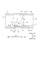
- FIG. 4 is a schematic view of the casing 9 when the casing 9 is cut in a cross section extending in substantially the same direction as the extending direction of the winding end portion 19 and extending in the axial direction of the centrifugal compressor 1. It is a cross-sectional view.
- FIG. 4 is also a view of the inside of the scroll flow path 13 at the winding end portion 19 as viewed from the radial outside of the centrifugal compressor 1.
- FIG. 5 is a schematic perspective view of the inside of the scroll flow path 13 as viewed from the C direction in FIG.
- the casing 9 is formed with a ridge 50.
- the ridge 50 is a portion of the scroll flow path 13 that projects from the inner peripheral surface 13a on the axially downstream side of the centrifugal compressor to the axially upstream side of the centrifugal compressor 1.
- the protrusion height HR projecting from the start point position Ps located on the upstream side of the scroll flow path 13 to the tongue portion 25 toward the tongue portion 25 is formed so as to gradually increase. ing. That is, in some embodiments, the ridge 50 begins to project axially upstream from the axially downstream inner peripheral surface 13a of the scroll flow path 13 at the start point position Ps, and gradually extends toward the tongue 25.
- the protrusion height HR is increased.
- the ridge 50 is connected to the tongue 25 on the downstream side of the scroll flow path 13.
- the inner peripheral surface 17a on the downstream side in the axial direction at the winding start portion 17 and the inner peripheral surface 19a on the downstream side in the axial direction at the winding end portion 19 are in the axial direction of the centrifugal compressor 1. The position is the same.
- the ridge 50 extends approximately along the circumferential direction of the centrifugal compressor 1 from the starting point position Ps toward the tongue 25.
- the center of the scroll flow path 13 that is, the position where the center line AX passes, extends the scroll flow path 13 in the radial direction of the centrifugal compressor 1 and is in the axis X direction of the rotation axis 3. It is assumed that it is the center of gravity (center of gravity) of the scroll flow path 13 on the extending virtual cut surface.
- the connection area 30 according to some embodiments will be described in detail.
- the fluid blown out from the diffuser 11 into the scroll flow path 13 flows into the scroll flow path 13 along the inner peripheral surface 13b on the downstream side in the axial direction of the inner peripheral surface 13a of the scroll flow path 13. Further, the fluid blown out from the diffuser 11 into the scroll flow path 13 has a velocity component toward the outside in the radial direction of the centrifugal compressor 1. Therefore, in the vicinity of the flow path connecting portion 20, the fluid blown out from the diffuser 11 into the scroll flow path 13 causes the ridge portion 50 to move from the inside to the outside in the radial direction of the centrifugal compressor 1, as shown by an arrow 97. I try to get over it. The flow of such a fluid flows toward the upstream side in the axial direction.
- the flow of the fluid in the scroll flow path 13 is accompanied by the above-mentioned main flow 91 and a swirling flow 93 that flows while swirling in the scroll flow path 13 along the main flow 91.
- the swirling flow 93 flows toward the downstream side in the axial direction. Therefore, as shown by the arrow 97, the flow of the fluid trying to get over the ridge 50 and the swirling flow 93 interfere with each other, and the fluid separates from the inner peripheral surface 13a of the scroll flow path 13 near the tongue portion 25. Will be invited. Such peeling causes a loss of the centrifugal compressor 1.
- the starting point position Ps is a position of 8 degrees or less at an angle ⁇ in the circumferential direction of the centrifugal compressor 1 from the tongue portion 25 toward the upstream side of the scroll flow path 13. In some embodiments, the starting point position Ps is more preferably a position of 4 degrees or less at the angle ⁇ .
- the starting point position Ps is set to a position of about 15 degrees at the above angle ⁇ .
- the starting point position Ps is a position of 8 degrees or less at the angle ⁇ . Therefore, in some embodiments, the range in which the ridge portion 50 extends in the circumferential direction of the centrifugal compressor 1 can be made smaller than that of a general centrifugal compressor. Since the ridge portion 50 is a portion of the inner peripheral surface 13a of the scroll flow path 13 that protrudes from the inner peripheral surface 13b on the downstream side in the axial direction toward the upstream side in the axial direction, the ridge portion 50 is the circumference of the centrifugal compressor 1.
- the centrifugal compressor 1 By reducing the range extending in the direction, it is possible to suppress the interference between the flow of the fluid trying to get over the ridge portion 50 and the swirling flow 93 in the scroll flow path 13 as shown by the arrow 97. Therefore, according to some embodiments, the separation of the fluid from the inner peripheral surface 13a of the scroll flow path 13 can be suppressed, so that the loss due to the separation can be suppressed. Therefore, in the centrifugal compressor 1, the efficiency can be improved in a wide operating range.
- FIG. 7 is a graph showing the relationship between the flow rate and the scroll outlet efficiency in the conventional centrifugal compressor and the centrifugal compressor 1 according to the above-described embodiment.
- the graph shown by the solid line is the graph for the centrifugal compressor 1 according to the above-described embodiment
- the graph shown by the broken line is the graph for the conventional centrifugal compressor.
- the protrusion height HR at a position of 4 degrees at an angle ⁇ in the circumferential direction of the centrifugal compressor 1 from the tongue portion 25 toward the upstream side of the scroll flow path 13 is the scroll flow at the winding start portion 17. It is 10% or less of the height dimension Ha along the axial direction of the centrifugal compressor 1 for the path 13.
- the ridge portion 50 in a general centrifugal compressor extends in a range of about 15 degrees in the circumferential angle of the centrifugal compressor.
- the protruding height HR1 of the ridge portion 50 at the connection position with the tongue portion 25 is the height along the axial direction of the centrifugal compressor for the scroll flow path 13 at the winding start portion 17. Often exceeds 50% of the dimension Ha. Therefore, in the ridge portion 50 of a general centrifugal compressor, the protruding height of the ridge portion 50 at a position of 4 degrees at an angle ⁇ in the circumferential direction of the centrifugal compressor from the tongue portion 25 toward the upstream side of the scroll flow path 13.
- the protruding height HR of the ridge portion 50 at a position of 4 degrees at an angle ⁇ in the circumferential direction of the centrifugal compressor 1 from the tongue portion 25 toward the upstream side of the scroll flow path 13 is set.
- the protruding height HR of the ridge portion 50 in the vicinity of the tongue portion 25 is generally set.
- the protruding height of the ridge 50 in a typical centrifugal compressor can be made smaller than the protruding height HR. Therefore, according to some embodiments, it is possible to suppress the interference between the flow of the fluid trying to get over the ridge portion 50 and the swirling flow 93 in the scroll flow path 13 as shown by the arrow 97. Therefore, according to some embodiments, the separation of the fluid from the inner peripheral surface 13a of the scroll flow path 13 can be suppressed, so that the loss due to the separation can be suppressed. Therefore, in the centrifugal compressor 1, the efficiency can be improved in a wide operating range.
- the protrusion height HR at a position of 4 degrees at an angle ⁇ in the circumferential direction of the centrifugal compressor 1 from the tongue portion 25 toward the upstream side of the scroll flow path 13 is a connection position with the tongue portion 25.
- the protrusion height in HR1 is 20% or less.
- the ridge portion 50 in a general centrifugal compressor extends in a range of about 15 degrees in the circumferential angle of the centrifugal compressor. Therefore, in the ridge portion 50 of a general centrifugal compressor, the protruding height HR of the ridge portion 50 at a position of 4 degrees at an angle in the circumferential direction of the centrifugal compressor from the tongue portion 25 toward the upstream side of the scroll flow path 13. Often exceeds 50% of the protrusion height HR1 at the connection position with the tongue portion 25.
- the protruding height HR of the ridge portion 50 at a position of 4 degrees at an angle ⁇ in the circumferential direction of the centrifugal compressor 1 from the tongue portion 25 toward the upstream side of the scroll flow path 13.
- the protrusion height HR of the ridge portion 50 in the vicinity of the tongue portion 25 is larger than the protrusion height of the ridge portion in a general centrifugal compressor. It can be made smaller. Therefore, according to some embodiments, interference between the flow of the fluid trying to get over the ridge 50 and the swirling flow 93 in the scroll flow path 13 can be suppressed as shown by the arrow 97.
- the separation of the fluid from the inner peripheral surface 13a of the scroll flow path 13 can be suppressed, so that the loss due to the separation can be suppressed. Therefore, in the centrifugal compressor 1, the efficiency can be improved in a wide operating range.
- the start point position Ps is set to a position of 8 degrees or less at the angle ⁇ . It may be carried out together with the embodiment or other embodiments described later, or may be carried out independently.
- the protruding height HR of the ridge portion 50 is 30% or less of the height dimension Ha along the axial direction of the centrifugal compressor 1 for the scroll flow path 13 at the winding start portion 17. ..
- the protrusion height HR at the ridge portion 50 is 30% or less of the height dimension Ha along the axial direction of the centrifugal compressor 1 for the scroll flow path 13 at the winding start portion 17. It has been found that the effect of suppressing the separation of the fluid from the inner peripheral surface 13a of the scroll flow path 13 is particularly enhanced. Therefore, according to some embodiments, the separation of the fluid from the inner peripheral surface 13a of the scroll flow path 13 can be effectively suppressed, so that the loss due to the separation can be effectively suppressed.
- the embodiment in which the start point position Ps is set to a position of 8 degrees or less at the angle ⁇ , or at the angle ⁇ . It may be carried out together with the embodiment in which the protrusion height HR at the position of 4 degrees is 20% or less of the above-mentioned protrusion height HR1, or may be carried out alone. Further, the above-described embodiment in which the protruding height HR of the ridge portion 50 is 30% or less of the above-mentioned height dimension Ha may be carried out together with other embodiments described later.
- the ridge 50 has a radius of curvature r (see FIG. 4) of a curve connecting the apex 51, which defines the protrusion height HR, from the tongue 25 to the start point position Ps on the upstream side in the axial direction. Further, the radius of curvature r gradually increases from the tongue portion 25 toward the start point position Ps at least a part of the top portion 51. That is, in some embodiments, in at least a portion of the apex 51, the radius of curvature r of the curve connecting the apex 51 from the tongue 25 to the start point position Ps decreases from the start point position Ps to the tongue 25.
- the amount of decrease in the protrusion height HR (dHR) when moving from the tongue portion 25 toward the start point position Ps by a minute distance dx is the region closer to the connection position with the tongue portion 25 having the highest protrusion height HR. large. Therefore, when moving from the tongue portion 25 toward the start point position Ps, the protrusion height HR sharply decreases in the region near the connection position with the tongue portion 25 as compared with the region far from the connection position with the tongue portion 25. Will be done. Therefore, according to some embodiments, the protrusion height HR can be suppressed as a whole, so that the flow of the fluid trying to get over the ridge 50 and the swirl in the scroll flow path 13 as shown by the arrow 97. Interference with the flow 93 can be suppressed. As a result, the separation of the fluid from the inner peripheral surface 13a of the scroll flow path 13 can be suppressed, so that the loss due to the separation can be suppressed.
- the above-described embodiment in which the radius of curvature r is gradually increased from the tongue portion 25 toward the start point position Ps may be carried out together with at least one of the above-mentioned embodiments, or may be carried out independently. Further, the above-described embodiment in which the radius of curvature r is gradually increased from the tongue portion 25 toward the start point position Ps may be carried out together with other embodiments described later.
- FIG. 6 is a diagram schematically showing the shape of the flow path at the winding end 19 of the scroll flow path 13 and the shape of the flow path of the outlet flow path 15, respectively, when viewed from the downstream side of the outlet flow path 15.
- the flow path shape of is shown.
- the flow path shape 13X in the cross section extending in the direction orthogonal to the center line AX of the scroll flow path 13 forms the tongue portion 25. Not circular in cross section including.
- the outlet flow path 15 has a flow path shape 15X in a cross section extending in a direction orthogonal to the center line AX of the exit flow path 15 at a connection position 15a with the scroll flow path 13 (FIG. 2). From (see) to the downstream side of the outlet flow path 15, it gradually approaches a circle, and is equal to or greater than the flow path height Hb (see FIG. 4) of the winding end portion 19 along the axial direction of the centrifugal compressor 1.
- the flow path shape 15X is circular at a position downstream of the outlet flow path from the connection position 15a.
- the scroll flow path 13 has a tongue portion 25 having a flow path shape (hereinafter, simply referred to as a cross-sectional shape) 13X in a cross section extending in a direction orthogonal to the center line AX of the scroll flow path 13. It is not circular in the cross section including.
- the outlet flow path 15 has a flow path shape (cross-sectional shape) 15X in a cross section extending in a direction orthogonal to the extending direction of the flow path, which is generally circular. Therefore, if the cross-sectional shape of the flow path suddenly changes from the scroll flow path 13 to the outlet flow path 15, a loss occurs and the efficiency of the centrifugal compressor 1 decreases.
- the cross-sectional shape of the flow path is made closer to a circle by a distance of the flow path height Hb or more of the winding end portion 19 along the axial direction of the centrifugal compressor 1. It turned out that the loss can be effectively suppressed. Therefore, according to some embodiments, the loss generated in the flow path from the scroll flow path 13 to the outlet flow path 15 can be effectively suppressed, and the efficiency of the centrifugal compressor 1 can be improved in a wide operating range. Can be done.
- the present invention is not limited to the above-described embodiment, and includes a modification of the above-described embodiment and a combination of these embodiments as appropriate.
Landscapes
- Engineering & Computer Science (AREA)
- Mechanical Engineering (AREA)
- General Engineering & Computer Science (AREA)
- Chemical & Material Sciences (AREA)
- Combustion & Propulsion (AREA)
- Structures Of Non-Positive Displacement Pumps (AREA)
- Supercharger (AREA)
Priority Applications (5)
| Application Number | Priority Date | Filing Date | Title |
|---|---|---|---|
| DE112019007280.3T DE112019007280T5 (de) | 2019-06-05 | 2019-06-05 | Scroll-struktur eines radialverdichters und radialverdichter |
| US17/614,891 US11905969B2 (en) | 2019-06-05 | 2019-06-05 | Scroll structure of centrifugal compressor and centrifugal compressor |
| JP2021524560A JP7134348B2 (ja) | 2019-06-05 | 2019-06-05 | 遠心圧縮機のスクロール構造及び遠心圧縮機 |
| CN201980095998.9A CN113785111B (zh) | 2019-06-05 | 2019-06-05 | 离心压缩机的涡旋构造和离心压缩机 |
| PCT/JP2019/022292 WO2020245934A1 (ja) | 2019-06-05 | 2019-06-05 | 遠心圧縮機のスクロール構造及び遠心圧縮機 |
Applications Claiming Priority (1)
| Application Number | Priority Date | Filing Date | Title |
|---|---|---|---|
| PCT/JP2019/022292 WO2020245934A1 (ja) | 2019-06-05 | 2019-06-05 | 遠心圧縮機のスクロール構造及び遠心圧縮機 |
Publications (1)
| Publication Number | Publication Date |
|---|---|
| WO2020245934A1 true WO2020245934A1 (ja) | 2020-12-10 |
Family
ID=73652283
Family Applications (1)
| Application Number | Title | Priority Date | Filing Date |
|---|---|---|---|
| PCT/JP2019/022292 Ceased WO2020245934A1 (ja) | 2019-06-05 | 2019-06-05 | 遠心圧縮機のスクロール構造及び遠心圧縮機 |
Country Status (5)
| Country | Link |
|---|---|
| US (1) | US11905969B2 (https=) |
| JP (1) | JP7134348B2 (https=) |
| CN (1) | CN113785111B (https=) |
| DE (1) | DE112019007280T5 (https=) |
| WO (1) | WO2020245934A1 (https=) |
Citations (3)
| Publication number | Priority date | Publication date | Assignee | Title |
|---|---|---|---|---|
| WO2012124388A1 (ja) * | 2011-03-17 | 2012-09-20 | 三菱重工業株式会社 | 遠心圧縮機のスクロール構造 |
| WO2017168650A1 (ja) * | 2016-03-30 | 2017-10-05 | 三菱重工業株式会社 | 圧縮機スクロール、および、遠心圧縮機 |
| WO2018003632A1 (ja) * | 2016-07-01 | 2018-01-04 | 株式会社Ihi | 遠心圧縮機 |
Family Cites Families (12)
| Publication number | Priority date | Publication date | Assignee | Title |
|---|---|---|---|---|
| US4872809A (en) * | 1987-03-06 | 1989-10-10 | Giw Industries, Inc. | Slurry pump having increased efficiency and wear characteristics |
| US7597541B2 (en) * | 2005-07-12 | 2009-10-06 | Robert Bosch Llc | Centrifugal fan assembly |
| JP2008075536A (ja) * | 2006-09-21 | 2008-04-03 | Mitsubishi Heavy Ind Ltd | 遠心圧縮機 |
| JP4865630B2 (ja) * | 2007-05-11 | 2012-02-01 | 三菱重工業株式会社 | 遠心式送風機 |
| JP4951583B2 (ja) * | 2008-04-28 | 2012-06-13 | 日立アプライアンス株式会社 | ターボ冷凍機 |
| PL2310691T3 (pl) * | 2008-06-06 | 2016-11-30 | Obudowa pompy | |
| JP5479316B2 (ja) | 2010-12-28 | 2014-04-23 | 三菱重工業株式会社 | 遠心圧縮機のスクロール構造 |
| JP6051056B2 (ja) * | 2013-01-15 | 2016-12-21 | 株式会社荏原製作所 | 渦巻ポンプ |
| WO2017072900A1 (ja) * | 2015-10-29 | 2017-05-04 | 三菱重工業株式会社 | スクロールケーシング及び遠心圧縮機 |
| JP6551541B2 (ja) * | 2015-12-10 | 2019-07-31 | 株式会社Ihi | 遠心圧縮機の吐出部構造 |
| JP6642711B2 (ja) * | 2016-07-01 | 2020-02-12 | 株式会社Ihi | 遠心圧縮機 |
| JP2019007425A (ja) * | 2017-06-26 | 2019-01-17 | 株式会社豊田中央研究所 | 遠心圧縮機、ターボチャージャ |
-
2019
- 2019-06-05 US US17/614,891 patent/US11905969B2/en active Active
- 2019-06-05 CN CN201980095998.9A patent/CN113785111B/zh active Active
- 2019-06-05 WO PCT/JP2019/022292 patent/WO2020245934A1/ja not_active Ceased
- 2019-06-05 JP JP2021524560A patent/JP7134348B2/ja active Active
- 2019-06-05 DE DE112019007280.3T patent/DE112019007280T5/de active Pending
Patent Citations (3)
| Publication number | Priority date | Publication date | Assignee | Title |
|---|---|---|---|---|
| WO2012124388A1 (ja) * | 2011-03-17 | 2012-09-20 | 三菱重工業株式会社 | 遠心圧縮機のスクロール構造 |
| WO2017168650A1 (ja) * | 2016-03-30 | 2017-10-05 | 三菱重工業株式会社 | 圧縮機スクロール、および、遠心圧縮機 |
| WO2018003632A1 (ja) * | 2016-07-01 | 2018-01-04 | 株式会社Ihi | 遠心圧縮機 |
Also Published As
| Publication number | Publication date |
|---|---|
| US11905969B2 (en) | 2024-02-20 |
| CN113785111A (zh) | 2021-12-10 |
| DE112019007280T5 (de) | 2022-01-27 |
| US20220235794A1 (en) | 2022-07-28 |
| CN113785111B (zh) | 2024-07-05 |
| JP7134348B2 (ja) | 2022-09-09 |
| JPWO2020245934A1 (https=) | 2020-12-10 |
Similar Documents
| Publication | Publication Date | Title |
|---|---|---|
| JP6109197B2 (ja) | ラジアルタービン動翼 | |
| JP5479316B2 (ja) | 遠心圧縮機のスクロール構造 | |
| JP7779998B2 (ja) | 斜流タービン及びターボチャージャ | |
| EP3708848B1 (en) | Centrifugal compressor and turbocharger comprising said centrifugal compressor | |
| EP3299635B1 (en) | Scroll casing and centrifugal compressor | |
| US11215057B2 (en) | Turbine wheel, turbine, and turbocharger | |
| JP6053993B1 (ja) | スクロールケーシング及び遠心圧縮機 | |
| JP2017193983A (ja) | コンプレッサ | |
| WO2018198808A1 (ja) | 遠心圧縮機 | |
| US11067094B2 (en) | Compressor scroll and centrifugal compressor | |
| JP7361214B2 (ja) | コンプレッサハウジングおよび遠心圧縮機 | |
| JP6770917B2 (ja) | 遠心圧縮機 | |
| JP2021011828A (ja) | 多段遠心圧縮機 | |
| JP7134348B2 (ja) | 遠心圧縮機のスクロール構造及び遠心圧縮機 | |
| JP7013316B2 (ja) | 遠心圧縮機 | |
| JP2020165374A (ja) | タービンおよび過給機 | |
| JPWO2018179112A1 (ja) | コンプレッサのスクロール形状及び過給機 | |
| CN116066412B (zh) | 有叶扩散器以及离心压缩机 | |
| JP2021124046A (ja) | 遠心圧縮機のディフューザ構造及び遠心圧縮機 | |
| US12031548B2 (en) | Scroll structure of centrifugal compressor and centrifugal compressor | |
| US12129764B2 (en) | Turbocharger gas casing and turbocharger | |
| JP2019218941A (ja) | 遠心圧縮機、ターボチャージャ | |
| JP6759463B2 (ja) | ターボチャージャ用タービン及びターボチャージャ |
Legal Events
| Date | Code | Title | Description |
|---|---|---|---|
| 121 | Ep: the epo has been informed by wipo that ep was designated in this application |
Ref document number: 19932203 Country of ref document: EP Kind code of ref document: A1 |
|
| ENP | Entry into the national phase |
Ref document number: 2021524560 Country of ref document: JP Kind code of ref document: A |
|
| 122 | Ep: pct application non-entry in european phase |
Ref document number: 19932203 Country of ref document: EP Kind code of ref document: A1 |