WO2020241027A1 - 回転電機 - Google Patents
回転電機 Download PDFInfo
- Publication number
- WO2020241027A1 WO2020241027A1 PCT/JP2020/013869 JP2020013869W WO2020241027A1 WO 2020241027 A1 WO2020241027 A1 WO 2020241027A1 JP 2020013869 W JP2020013869 W JP 2020013869W WO 2020241027 A1 WO2020241027 A1 WO 2020241027A1
- Authority
- WO
- WIPO (PCT)
- Prior art keywords
- terminal
- substrate
- heat sink
- press
- holder
- Prior art date
- Legal status (The legal status is an assumption and is not a legal conclusion. Google has not performed a legal analysis and makes no representation as to the accuracy of the status listed.)
- Ceased
Links
Images






Classifications
-
- H—ELECTRICITY
- H02—GENERATION; CONVERSION OR DISTRIBUTION OF ELECTRIC POWER
- H02K—DYNAMO-ELECTRIC MACHINES
- H02K5/00—Casings; Enclosures; Supports
- H02K5/04—Casings or enclosures characterised by the shape, form or construction thereof
- H02K5/22—Auxiliary parts of casings not covered by groups H02K5/06-H02K5/20, e.g. shaped to form connection boxes or terminal boxes
- H02K5/225—Terminal boxes or connection arrangements
-
- H—ELECTRICITY
- H02—GENERATION; CONVERSION OR DISTRIBUTION OF ELECTRIC POWER
- H02K—DYNAMO-ELECTRIC MACHINES
- H02K11/00—Structural association of dynamo-electric machines with electric components or with devices for shielding, monitoring or protection
- H02K11/20—Structural association of dynamo-electric machines with electric components or with devices for shielding, monitoring or protection for measuring, monitoring, testing, protecting or switching
- H02K11/21—Devices for sensing speed or position, or actuated thereby
- H02K11/215—Magnetic effect devices, e.g. Hall-effect or magneto-resistive elements
-
- H—ELECTRICITY
- H02—GENERATION; CONVERSION OR DISTRIBUTION OF ELECTRIC POWER
- H02K—DYNAMO-ELECTRIC MACHINES
- H02K11/00—Structural association of dynamo-electric machines with electric components or with devices for shielding, monitoring or protection
- H02K11/30—Structural association with control circuits or drive circuits
- H02K11/33—Drive circuits, e.g. power electronics
-
- H—ELECTRICITY
- H02—GENERATION; CONVERSION OR DISTRIBUTION OF ELECTRIC POWER
- H02K—DYNAMO-ELECTRIC MACHINES
- H02K3/00—Details of windings
- H02K3/46—Fastening of windings on the stator or rotor structure
- H02K3/50—Fastening of winding heads, equalising connectors, or connections thereto
-
- H—ELECTRICITY
- H02—GENERATION; CONVERSION OR DISTRIBUTION OF ELECTRIC POWER
- H02K—DYNAMO-ELECTRIC MACHINES
- H02K5/00—Casings; Enclosures; Supports
- H02K5/04—Casings or enclosures characterised by the shape, form or construction thereof
- H02K5/10—Casings or enclosures characterised by the shape, form or construction thereof with arrangements for protection from ingress, e.g. water or fingers
-
- H—ELECTRICITY
- H02—GENERATION; CONVERSION OR DISTRIBUTION OF ELECTRIC POWER
- H02K—DYNAMO-ELECTRIC MACHINES
- H02K9/00—Arrangements for cooling or ventilating
- H02K9/22—Arrangements for cooling or ventilating by solid heat conducting material embedded in, or arranged in contact with, the stator or rotor, e.g. heat bridges
- H02K9/227—Heat sinks
-
- H—ELECTRICITY
- H02—GENERATION; CONVERSION OR DISTRIBUTION OF ELECTRIC POWER
- H02K—DYNAMO-ELECTRIC MACHINES
- H02K2203/00—Specific aspects not provided for in the other groups of this subclass relating to the windings
- H02K2203/09—Machines characterised by wiring elements other than wires, e.g. bus rings, for connecting the winding terminations
-
- H—ELECTRICITY
- H02—GENERATION; CONVERSION OR DISTRIBUTION OF ELECTRIC POWER
- H02K—DYNAMO-ELECTRIC MACHINES
- H02K2211/00—Specific aspects not provided for in the other groups of this subclass relating to measuring or protective devices or electric components
- H02K2211/03—Machines characterised by circuit boards, e.g. pcb
-
- H—ELECTRICITY
- H02—GENERATION; CONVERSION OR DISTRIBUTION OF ELECTRIC POWER
- H02K—DYNAMO-ELECTRIC MACHINES
- H02K3/00—Details of windings
- H02K3/46—Fastening of windings on the stator or rotor structure
- H02K3/52—Fastening salient pole windings or connections thereto
- H02K3/521—Fastening salient pole windings or connections thereto applicable to stators only
- H02K3/522—Fastening salient pole windings or connections thereto applicable to stators only for generally annular cores with salient poles
Definitions
- the present invention relates to a rotary electric machine.
- Patent Document 1 discloses a connection structure between a motor wire (bus bar) of a motor and a connection terminal of a substrate.
- the connection terminal is formed in a substantially hat-shaped plate shape, and the fixing portions constituting both ends in the longitudinal direction of the connection terminal are soldered to the substrate.
- an insertion hole is formed in the intermediate portion in the longitudinal direction of the connection terminal, and a pair of elastic portions are formed at the edge portion of the insertion hole. Then, by inserting (press-fitting) the motor wire between the pair of elastic portions, the connection terminal and the motor wire are connected.
- connection structure there is room for improvement in the following points. That is, if the motor wire is press-fitted with respect to the pair of elastic portions, an excessive stress may be generated in the fixed portion of the connection terminal and the soldered portion between the substrate. At this time, if a crack or the like occurs in the soldered portion, a connection failure may occur between the connection terminal and the substrate, and the reliability of the motor may decrease. Therefore, it is desirable that the connection structure is such that the motor wire can be press-fitted into the connection terminal while improving the reliability.
- an object of the present invention is to provide a rotary electric machine capable of press-fitting a bus bar into a connection terminal while improving reliability.
- One or more embodiments of the present invention include a substrate provided with a connector on one side surface, and a motor unit provided on one side of the substrate in the plate thickness direction and having a bus bar connected to the connector.
- the connector has a connection terminal that is press-fitted and fixed to the bus bar, and a holder that holds the connection terminal and is grounded on one side surface of the board.
- the connection terminal is one end of the connection terminal. , Which is held by the holder, and which constitutes the fixing portion fixed to the substrate and the other end of the connection terminal, is press-fitted and fixed to the bus bar, and is fixed in the thickness direction of the substrate.
- a terminal connecting portion that is offset from the fixed portion in the first direction orthogonal to the fixed portion and is separated from the substrate on one side in the plate thickness direction of the substrate, and the fixed portion and the terminal connecting portion. It is a rotary electric machine which is configured to include a connecting portion which is configured to be flexible and deformable in the plate thickness direction of the substrate.
- connection terminal has a groove portion to be press-fitted and fixed to the bus bar, and the connecting portion is arranged on the substrate side of the groove portion. It is a characteristic rotating electric machine.
- connection terminal is formed in a plate shape having a second direction orthogonal to the first direction as the plate thickness direction when viewed from the plate thickness direction of the substrate.
- the rotary electric machine is characterized in that a pair of press-fitting portions that are bent in the plate thickness direction of the connection terminal and press-fitted and fixed to the bus bar are formed at the edge portion of the groove portion.
- One or more embodiments of the present invention is a rotary electric machine, characterized in that the holder has a support portion that supports the connecting portion from the substrate side.
- the fixing portion is formed with a pair of terminal portions extending in the plate thickness direction of the substrate and arranged in the first direction, and the pair of terminal portions.
- the holder includes a base portion grounded on one side surface of the substrate and a holder portion that protrudes from the base portion toward the motor portion and holds the fixed portion.
- a cover portion that protrudes from the base portion toward the motor portion and covers a part of the connecting portion and the terminal connecting portion so as to be relatively displaceable in the plate thickness direction of the substrate. It is a characteristic rotary electric machine.
- the motor portion has a bottomed tubular housing in which one end in the axial direction is closed, and the substrate is fixed to an opening of the housing.
- a pair of heat sink-side positioning holes are formed in the heat sink, a pair of substrate-side positioning holes are formed in the substrate, and the heat sink-side positioning holes are formed in the base portion.
- the rotary electric motor is characterized in that a pair of positioning pins fitted in the substrate-side positioning holes are formed.
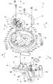
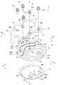
- FIG. 5 is an exploded perspective view of the ECU unit shown in FIG. 4 as viewed from below.
- FIG. 5 is an exploded perspective view of the ECU unit shown in FIG. 4 as viewed from above.
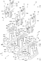
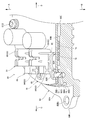
- FIG. 5 is an exploded perspective view of the connector shown in FIG. 5 as viewed from below. It is sectional drawing which shows the holding state of the connection terminal to the terminal holder in the connector shown in FIG. 4 (cross-sectional view of line 10-10 of FIG. 4).
- FIG. 5 is a perspective sectional view showing a state in which the positioning pin of the terminal holder in the connector shown in FIG. 4 is fitted in the positioning hole on the first heat sink side of the heat sink.
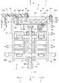
- the rotary electric machine 10 is configured as a rotary electric machine applied to a steering device of a vehicle (automobile). As shown in FIGS. 1 and 2, the rotary electric machine 10 is formed in a substantially columnar shape as a whole. Further, the rotary electric machine 10 includes a motor unit 12 and an ECU unit 14 for controlling the rotation of the motor unit 12. Hereinafter, each configuration of the rotary electric machine 10 will be described.
- one side in the axial direction of the rotary electric machine 10 is the lower side of the rotary electric machine 10, and the other side in the axial direction of the rotary electric machine 10 (FIGS. 1 and 2).
- Arrow B direction side is the upper side of the rotary electric machine 10.
- the direction orthogonal to the vertical direction is defined as the first direction (see arrows C and D in FIGS. 1 and 2) in a plan view viewed from above, and the direction is relative to the first direction.
- the direction orthogonal to each other is the second direction (see arrow E and arrow F in FIG. 1).
- the overhead line that passes through the axis AL of the rotary electric machine 10 and extends in the first direction is set as the first reference line L1 (see FIGS. 4 and 7), and passes through the axis AL of the rotary electric machine 10.
- the overhead line extending in the second direction is the second reference line L2 (see FIGS. 4 and 7).
- the motor unit 12 is configured as a three-phase alternating current brushless motor.
- the motor unit 12 includes a housing 20, a plate holder 24 housed in the housing 20, a rotating shaft 28, a stator 34, a rotor 40, and a bus bar unit 46.
- the housing 20 is formed in a substantially bottomed cylindrical shape that is open to the upper side, and constitutes the outer shell of the rotary electric machine 10.
- a pair of mounting pieces 20A are integrally formed on the outer peripheral portion of the lower end portion of the housing 20.
- the pair of mounting pieces 20A are arranged with the axial direction of the housing 20 as the plate thickness direction, and one side of the housing 20 in the first direction (the side in the direction of arrow C in FIGS. 1 and 2) and the other side in the first direction (FIG. It protrudes in the direction of arrow D in 1 and 2).
- a mounting hole 20A1 is formed through the mounting piece 20A. Then, a fastening member such as a bolt (not shown) is inserted into the mounting hole 20A1, and the housing 20 (that is, the rotary electric machine 10) is fixed to the steering device by the fastening member.
- a plurality of fixing portions 20B (three locations in the present embodiment) extending outward in the radial direction are formed on the outer peripheral portion of the opening end portion of the housing 20. Then, one fixing portion 20B is projected from the housing 20 to one side in the first direction, and three fixing portions 20B are arranged at equal intervals in the circumferential direction of the housing 20.
- a screw portion 20B1 for fixing the heat sink 60 which will be described later, is formed through the fixing portion 20B, and a female screw is formed on the inner peripheral surface of the screw portion 20B1.
- a bottomed cylindrical fixed cylinder portion 20C that is raised downward is integrally formed in the central portion of the bottom wall of the housing 20, and a rotating shaft 28 described later is provided in the fixed cylinder portion 20C.
- a first bearing 22 for supporting is fitted.
- An insertion hole 20C1 for inserting a rotating shaft 28, which will be described later, is formed through the bottom wall of the fixed cylinder portion 20C, and the inside of the first bearing 22 and the outside of the housing 20 are communicated with each other by the insertion hole 20C1. There is.
- the plate holder 24 is formed in a substantially circular plate shape with the vertical direction as the plate thickness direction, and is fitted in the intermediate portion in the vertical direction of the housing 20.
- a second bearing 26 for supporting the rotating shaft 28, which will be described later, is fixed to the central portion of the plate holder 24, and the second bearing 26 and the first bearing 22 are arranged coaxially.
- the rotating shaft 28 is formed in the shape of a round bar extending in the vertical direction, and is arranged coaxially with the housing 20 inside the housing 20.
- the lower end side portion of the rotating shaft 28 is rotatably supported by the first bearing 22, and the upper end side portion of the rotating shaft 28 is rotatably supported by the second bearing 26.
- the upper end of the rotating shaft 28 projects upward with respect to the plate holder 24, and the magnet 30 is fixed to the upper end.
- the lower end of the rotating shaft 28 projects downward with respect to the bottom wall of the housing 20, and the gear 32 connected to the steering device is fixed to the lower end.
- the stator 34 is arranged inside the housing 20 on the lower side of the plate holder 24 and on the outer side in the radial direction of the rotating shaft 28.
- the stator 34 has a stator core 36 made of a magnetic material, and the stator core 36 is formed in a cylindrical shape and is fitted inside the housing 20. Further, a winding 38 corresponding to the U phase, the V phase, and the W phase is wound around the stator core 36.
- the rotor 40 has a rotor core 42, and the rotor core 42 is formed in a cylindrical shape with the vertical direction as the axial direction, and is arranged inside the stator 34 in the radial direction. Then, the rotating shaft 28 is fitted into the shaft core portion of the rotor core 42, and the rotor core 42 (rotor 40) and the rotating shaft 28 are configured to be integrally rotatable. Further, a plurality of magnets 44 (permanent magnets) are fixed in the rotor core 42. As a result, the rotor 40 and the rotating shaft 28 are integrally rotated around the axis AL by passing a current through the U-phase, V-phase, and W-phase windings 38 of the stator 34.
- the bus bar unit 46 is arranged above the stator 34 and is held by the plate holder 24.
- the bus bar unit 46 includes three bus bars 48 corresponding to the U-phase, V-phase, and W-phase windings 38 of the stator 34, and a bus bar holder 50 for holding the bus bar 48.
- one end of the bus bar 48 is connected to the U-phase, V-phase, and W-phase windings 38 of the stator 34.
- the other end of the bus bar 48 is configured as the bus bar terminal portion 48A, and the bus bar terminal portion 48A protrudes upward from the plate holder 24 and is arranged side by side in the second direction.
- the bus bar terminal portion 48A is formed in a substantially long plate shape having a first direction as a plate thickness direction and extending in the vertical direction. Then, the bus bar terminal portion 48A is connected to the connection terminal 86 of the connector 80 described later.
- the ECU unit 14 is assembled to the open end portion of the housing 20 to form the upper end portion of the rotary electric machine 10.
- the ECU unit 14 includes a heat sink 60, a circuit board 70 as a "board” for controlling the motor unit 12, and a connector assembly 90 connected to the circuit board 70.
- the heat sink 60 is made of an aluminum alloy having high thermal conductivity or the like.
- the heat sink 60 is formed in a substantially disk shape with the vertical direction as the plate thickness direction.
- a flange portion 60A extending radially outward is integrally formed on the outer peripheral portion of the upper end portion of the heat sink 60, and the flange portion 60A is formed over the entire circumference of the heat sink 60 in the circumferential direction.
- the heat sink 60 is fitted into the opening of the housing 20 from above, and the flange portion 60A is arranged adjacent to the upper side of the opening end surface of the housing 20.
- the opening of the housing 20 is closed by the heat sink 60. That is, the heat sink 60 is configured as the lid portion of the housing 20, and also constitutes a part of the outer shell of the rotary electric machine 10.
- the flange portion 60A at a position corresponding to the screw portion 20B1 of the housing 20, three first fixing portions 60B protruding outward in the radial direction are integrally formed.
- a fixing hole 60B1 is formed through the first fixing portion 60B. Then, the fixing screw SC1 is inserted into the fixing hole 60B1 from above and screwed into the screw portion 20B1 of the housing 20, so that the heat sink 60 is fixed to the housing 20.
- a pair of second fixing portions 60C extending radially outward are integrally formed on the other side portion of the flange portion 60A in the first direction, and the second fixing portion 60C is the circumference of the heat sink 60. They are arranged side by side in the direction.
- a first fixing screw portion 60C1 for fixing the connector assembly 90, which will be described later, is formed through the second fixing portion 60C, and a female screw is formed on the inner peripheral surface of the first fixing screw portion 60C1. ing.
- a seal groove 60D is formed in the vertical intermediate portion of the outer peripheral portion of the heat sink 60.
- the seal groove 60D is opened to the outside in the radial direction of the heat sink 60, and extends over the entire circumference of the heat sink 60 in the circumferential direction.
- a ring-shaped O-ring OL is housed in the seal groove 60D, and the O-ring OL is made of an elastic member such as rubber.
- a grounding portion 61 for grounding the circuit board 70 is formed on the outer peripheral portion of the lower surface 60E of the heat sink 60.
- the ground contact portion 61 projects downward from the lower surface 60E of the heat sink 60, and is formed in a rib shape extending along the circumferential direction of the heat sink 60. Further, most of the ground contact portion 61 is formed on the outer peripheral portion of the heat sink 60 on one side in the first direction, and the ground contact portion 61 is substantially opened to the other side in the first direction when viewed from below. It is formed in a C shape.
- a step portion 62 which is one step lower than the ground contact portion 61 is formed on the other side portion in the first direction. Further, both ends of the ground contact portion 61 in the longitudinal direction are arranged on the other side in the first direction with respect to the second reference line L2 in a bottom view (see FIG. 7). That is, the length of the ground contact portion 61 in the longitudinal direction is set to 1 ⁇ 2 or more of the total length in the circumferential direction of the heat sink 60.
- the grounding portion 61 has three first substrate fixing portions 63A, a second substrate fixing portion 63B, and a third substrate fixing portion 63C protruding inward in the radial direction of the heat sink 60.
- the tip surface (lower surface) of the board fixing portion 63A to the third substrate fixing portion 63C is arranged flush with the tip surface (lower surface) of the grounding portion 61.
- the first board fixing portion 63A, the second board fixing portion 63B, and the third board fixing portion 63C have a concave first board fixing screw portion 63A1, a second board fixing screw portion 63B1, and a second board fixing screw portion 63B1 open downward.
- Each of the three board fixing screw portions 63C1 is formed.
- first substrate fixing portion 63A is formed at the end portion on one side in the longitudinal direction of the ground contact portion 61, and is on one side in the second direction (the side in the arrow E direction in FIG. 7) with respect to the first reference line L1. It is arranged on the other side of the first direction with respect to the second reference line L2.
- the second substrate fixing portion 63B is formed on one side of the ground contact portion 61 in the longitudinal direction.
- the second substrate fixing portion 63B is arranged on one side in the second direction with respect to the first reference line L1 and on one side in the first direction with respect to the second reference line L2 in a bottom view.
- the third substrate fixing portion 63C is formed on the other side portion in the longitudinal direction of the ground contact portion 61.
- the third substrate fixing portion 63C is on the other side in the second direction (the side in the arrow F direction in FIG. 7) with respect to the first reference line L1 and in the first direction with respect to the second reference line L2 in the bottom view. It is arranged slightly offset to one side.
- a fourth substrate fixing portion 63D for fixing the circuit board 70 is formed on the lower surface 60E of the heat sink 60.
- the fourth substrate fixing portion 63D is formed in a substantially cylindrical shape having a relatively low height protruding downward, and the tip surface (lower surface) of the fourth substrate fixing portion 63D is the tip surface (lower surface) of the ground contact portion 61. It is arranged flush with the lower surface).
- a fourth substrate fixing screw portion 63D1 is formed inside the fourth substrate fixing portion 63D, and a female screw is formed on the inner surface of the fourth substrate fixing screw portion 63D1. Further, the fourth substrate fixing portion 63D is arranged at a position on the other side in the second direction with respect to the first reference line L1 and on one side in the first direction with respect to the second reference line L2 in a bottom view.
- a portion of the heat sink 60 on one side in the first direction (specifically, a portion on one side in the first direction with respect to the second reference line L2) is used to dissipate heat generated by the FET 74 of the circuit board 70 described later. It is configured as a heat radiating unit 65.
- the heat radiating portion 65 is formed with a first radiating portion 65A, a second radiating portion 65B, and a third radiating portion 65C protruding downward from the lower surface 60E of the heat sink 60.
- the first heat radiating unit 65A to the third heat radiating unit 65C are formed in a substantially rectangular shape with the first direction as the longitudinal direction in the bottom view.
- the amount of protrusion from the lower surface 60E of the first heat radiation unit 65A to the third heat radiation unit 65C is set to be smaller than the amount of protrusion from the lower surface 60E of the ground contact portion 61. That is, the lower surfaces of the first heat radiating portion 65A to the third heat radiating portion 65C are arranged above the lower surface of the grounding portion 61.
- the first heat radiating unit 65A to the third heat radiating unit 65C are arranged side by side with a predetermined interval in the second direction.
- the first heat radiating portion 65A is arranged between the third substrate fixing portion 63C and the fourth substrate fixing portion 63D in a bottom view.
- the third substrate fixing portion 63C, the first heat radiating portion 65A, and the fourth substrate fixing portion 63D are arranged side by side in this order on one side in the second direction.
- the second heat radiating portion 65B and the third heat radiating portion 65C are arranged side by side in the second direction at a position between the second substrate fixing portion 63B and the fourth substrate fixing portion 63D in a bottom view.
- the fourth substrate fixing portion 63D, the second heat radiating portion 65B, the third heat radiating portion 65C, and the second substrate fixing portion 63B are arranged side by side in this order on one side in the second direction.
- a pair of positioning portions 66, 67 for determining the position of the connector 80 of the circuit board 70, which will be described later, are formed on the lower surface 60E of the heat sink 60.
- the positioning portions 66 and 67 project downward from the lower surface 60E of the heat sink 60, and the amount of protrusion of the positioning portions 66 and 67 from the lower surface 60E is set to be smaller than the amount of protrusion of the ground contact portion 61 from the lower surface 60E.
- the positioning portions 66 and 67 are arranged on the outer peripheral side of the lower surface 60E of the heat sink 60 on one side in the first direction, and are arranged adjacent to the inner side in the radial direction of the ground contact portion 61.
- the pair of positioning portions 66, 67 are arranged at positions symmetrical with respect to the first reference line L1 in the second direction in the bottom view.
- a first heat sink side positioning hole 66A is formed as a concave "heat sink side positioning hole” opened downward, and a first heat sink side positioning hole 66A is formed. Is formed in a circular shape in a bottom view.
- a second heat sink side positioning hole 67A as a concave "heat sink side positioning hole” opened downward is formed on the lower surface of the positioning portion 67 on the other side in the second direction, and the second heat sink side positioning is performed.
- the hole 67A is formed in a substantially track shape with the second direction as the longitudinal direction in the bottom view.
- the heat sink 60 is formed with a pair of first heat sink side positioning holes 66A and second heat sink side positioning holes 67A, and the first heat sink side positioning holes 66A and the second heat sink side positioning holes 67A are formed in the second direction. They are arranged side by side.
- the width direction (first direction) of the second heat sink side positioning hole 67A is set to match the diameter of the first heat sink side positioning hole 66A.
- the lower surface 60E of the heat sink 60 is formed with a recess 60F that is open downward in a portion other than the heat radiating portion 65 (the other side portion in the first direction), and the recess 60F has a substantially hexagonal shape in a bottom view. Is formed in.
- the terminal insertion portion 60G is formed in a substantially V shape that is open to one side in the first direction in a bottom view.
- a meat relief 60H opened upward is formed on one side portion in the first direction, and the meat relief 60H is formed in a substantially fan shape in a plan view. Has been done.
- Part 60J is formed on the upper surface of the heat sink 60.
- the second fixing screw portion 60J is formed in a concave shape that is open to the upper side of the heat sink 60, and a female screw is formed on the inner peripheral surface of the second fixing screw portion 60J. Then, the second fixing screw portions 60J at three positions are arranged at predetermined intervals in the second direction in a plan view.
- the circuit board 70 is formed in a disk shape with the vertical direction as the plate thickness direction, and the diameter of the circuit board 70 is set to be slightly smaller than the diameter of the heat sink 60. Has been done.
- the circuit board 70 is arranged coaxially with the heat sink 60 and adjacent to the lower side of the grounding portion 61 of the heat sink 60. As a result, a gap G (see FIG. 4B) is formed in the vertical direction between the outer peripheral portion of the circuit board 70 on the other side in the first direction and the stepped portion 62 of the heat sink 60. ..
- the circuit board 70 is formed through four board fixing holes 70A (see FIG. 6) at positions corresponding to the first board fixing screw portions 63A1 to the fourth board fixing screw portion 63D1 of the heat sink 60. .. Then, the fixing screw SC2 is inserted into the board fixing hole 70A from below and screwed into the first board fixing screw portion 63A1 to the fourth board fixing screw portion 63D1 to fix the circuit board 70 to the heat sink 60. Has been done. As a result, the motor unit 12 is arranged on one side (lower side) of the circuit board 70 in the plate thickness direction.
- a magnetic sensor 72 is provided (mounted) in the center of the lower surface (one side surface) of the circuit board 70.
- the magnetic sensor 72 is arranged close to the upper side of the magnet 30 on the rotating shaft 28 of the motor unit 12, and the magnetic sensor 72 and the magnet 30 are arranged so as to face each other in the vertical direction (see FIG. 2). As a result, the rotation amount (rotation angle) of the rotation shaft 28 is detected by the magnetic sensor 72.
- FIGS. 6 and 7 on the upper surface (other side surface) of the circuit board 70, a plurality of regions (regions vertically facing the heat radiating portion 65 of the heat sink 60) on one side in the first direction are formed.
- An FET 74 heat generating element
- the plurality of FETs 74 are arranged at positions corresponding to the first heat radiating section 65A, the second heat radiating section 65B, and the third heat radiating section 65C of the heat sink 60.
- a pair of FET 74s are arranged at positions corresponding to the first heat radiation unit 65A, the second heat radiation unit 65B, and the third heat radiation unit 65C of the heat sink 60, and the pair of FET 74s are arranged. Are arranged side by side in the first direction (see FIG. 7). Further, in the fixed state of the circuit board 70 to the heat sink 60, a slight gap is formed in the vertical direction between the FET 74 and the first heat radiation unit 65A, the second heat radiation unit 65B, and the third heat radiation unit 65C.
- the amount of protrusion is set from the lower surface 60E of the heat sink 60 of the first heat radiation unit 65A, the second heat radiation unit 65B, and the third heat radiation unit 65C (see FIG. 11). Then, grease or the like for heat dissipation is interposed in the gap.
- a pair of circular substrate-side positioning holes 70B are formed through the circuit board 70 at positions corresponding to the first heat sink-side positioning holes 66A and the second heat sink-side positioning holes 67A of the heat sink 60. ing.
- the diameter dimension of the substrate side positioning hole 70B is set to be substantially the same as the diameter dimension of the first heat sink side positioning hole 66A.
- the lower surface of the circuit board 70 has a portion on one side in the first direction (specifically, a position corresponding to the bus bar terminal portion 48A described above).
- a connector 80 for connecting the circuit board 70 and the motor unit 12 (three bus bars 48) is provided.
- the connector 80 will be described.
- the connector 80 is a terminal as a "holder” for holding the three connection terminals 86 and the three connection terminals 86. It is configured to include the holder 81. Then, the bus bar terminal portion 48A of the bus bar 48 is press-fitted into the connection terminal 86, and the motor portion 12 and the connection terminal 86 are connected. That is, the connector 80 is configured as a so-called press-fit connector.
- the terminal holder 81 is made of a resin material (insulating material).
- the terminal holder 81 is formed in a substantially E-shaped block shape that is open downward when viewed from the first direction.
- the terminal holder 81 includes a base portion 82 that constitutes the base end portion (upper end portion) of the terminal holder 81, and three holding main bodies that protrude downward (motor portion 12 side) from the base portion 82. It is configured to include part 83.
- the base portion 82 is formed in a substantially rectangular plate shape with the vertical direction as the plate thickness direction and the second direction as the longitudinal direction, and is grounded on the lower surface of the circuit board 70. Then, the base portion 82 is arranged with respect to the circuit board 70 so that the central portion in the longitudinal direction of the base portion 82 coincides with the first reference line L1 in the bottom view (see FIG. 4).
- a pair of hole portions 82A are formed through the base portion 82, and the hole portions 82A are arranged at positions symmetrical with respect to the first reference line L1 in the second direction in a bottom view.
- the hole 82A is formed in a substantially track shape with the first direction as the longitudinal direction. Then, the head of the fixing screw SC2 is arranged in the hole 82A on the other side in the second direction.
- the base portion 82 is integrally formed with a pair of positioning pieces 82B extending to one side in the first direction at positions corresponding to the pair of hole portions 82A.
- a positioning pin 82C is formed at the tip of the positioning piece 82B, and the positioning pin 82C is bottomed so as to protrude upward (to the circuit board 70 side) from the positioning piece 82B and open to the lower side. It is formed in a cylindrical shape. Further, the diameter of the positioning pin 82C is set to be substantially the same as the diameter of the substrate side positioning hole 70B of the circuit board 70 and the first heat sink side positioning hole 66A of the heat sink 60.
- the positioning pin 82C on one side in the second direction is fitted in the substrate side positioning hole 70B of the circuit board 70 and in the first heat sink side positioning hole 66A of the heat sink 60 (see FIG. 11). Further, the positioning pin 82C on the other side in the second direction is fitted in the substrate side positioning hole 70B of the circuit board 70 and in the second heat sink side positioning hole 67A of the heat sink 60. As a result, the position of the terminal holder 81 (that is, the connector 80) with respect to the heat sink 60 is determined by the positioning pin 82C.
- the three holding main body portions 83 are projected downward from both ends in the longitudinal direction and the central portion in the longitudinal direction of the base portion 82, respectively.
- the holding main body portion 83 extends along the width direction (first direction) of the base portion 82 in a bottom view. Further, the holding main body 83 includes a holder portion 84 that constitutes one end in the first direction of the holding main body 83, and a cover portion 85 that constitutes the other end in the first direction of the holding main body 83. It is configured.
- the holder portion 84 is formed in the shape of a substantially rectangular parallelepiped block protruding downward from the base portion 82.
- a pair of holding holes 84A1 and 84A2 are formed in the holder portion 84 at the center portion in the width direction (second direction) of the holding main body portion 83, and the holding holes 84A1 and 84A2 are penetrated in the vertical direction. That is, the holding holes 84A1 and 84A2 also penetrate the base portion 82.
- the holding holes 84A1 and 84A2 are formed in a substantially rectangular shape in a bottom view, and are arranged side by side along the first direction.
- the holding holes 84A2 arranged on the other side in the first direction are arranged at the other end of the holder portion 84 in the first direction, and the holding holes 84A2 are arranged at the other end of the holder portion 84 in the first direction.
- the 84A2 is open to the other side in the first direction in a bottom view.
- the dimensions of the holding holes 84A1 and 84A2 in the second direction are set to be slightly larger than the plate thickness of the connection terminal 86 described later.
- the cover portion 85 is formed in a substantially U-shaped columnar shape open to one side in the first direction when viewed from the bottom, and is formed in a substantially flat shape with the second direction as the thickness direction.
- the cover portion 85 includes a pair of first side walls 85A having a plate thickness direction in the second direction and a second side wall 85B connecting the ends of the pair of first side walls 85A on the other side in the first direction. , Is included.
- the amount of protrusion of the cover portion 85 from the base portion 82 is significantly larger than the amount of protrusion of the holder portion 84 from the base portion 82.
- one end in the first direction at the base end of the pair of first side walls 85A is connected to the holder 84.
- the inside of the cover portion 85 is configured as an accommodating portion 85C for accommodating the connection terminal 86 described later.
- a guide groove 85D is formed at the tip end portion (lower end portion) of the pair of first side wall 85A at the intermediate portion in the first direction.
- the guide groove 85D is formed in a slit shape extending in the vertical direction and is penetrated in the second direction.
- a pair of inclined portions 85E are formed at the opening end of the guide groove 85D, and the inclined portions 85E are separated from each other toward the lower side (opening side of the guide groove 85D) (width direction of the guide groove 85D). It is tilted to the outside).
- the groove width of the guide groove 85D is set to be slightly larger than the plate thickness of the bus bar terminal portion 48A, and in the connected state between the connection terminal 86 and the bus bar terminal portion 48A described later, the bus bar terminal portion 48A is set as the guide groove. It is designed to be inserted in the 85D.
- a pair of guide ribs 85F are formed on the inner peripheral surfaces of the pair of first side walls 85A.
- the guide ribs 85F are arranged on one side and the other side in the first direction with respect to the guide groove 85D, respectively, and extend downward from the base portion 82.
- the guide ribs 85F arranged to face each other in the second direction form a set, and the separation distance of the set guide ribs 85F in the second direction substantially matches the plate thickness of the connection terminal 86 described later. It is set.
- An inclined surface 85G is formed at the tip of the guide rib 85F, and the inclined surface 85G is inclined toward the first side wall 85A as it goes downward.
- the support projection portion 85H as the “support portion” (see FIG. 10).
- the support protrusion 85H protrudes downward from the base portion 82, and the amount of protrusion of the support protrusion 85H from the base portion 82 is smaller than the amount of protrusion of the holder portion 84 from the base portion 82. .. Further, the support protrusion 85H is formed in a substantially trapezoidal shape in a cross-sectional view seen from the second direction.
- connection terminal 86 As shown in FIGS. 9 and 10, the connection terminal 86 is made of a metal plate material. Further, the connection terminal 86 is arranged with the second direction as the plate thickness direction, and is held by each of the three holding main body portions 83 in the terminal holder 81. The connection terminal 86 is formed in a substantially crank-shaped plate shape when viewed from the second direction. Specifically, the connection terminal 86 includes a terminal fixing portion 87 as a "fixing portion" constituting one end portion (one end portion on one side in the first direction) of the connection terminal 86 and the other end portion (the second end portion) of the connection terminal 86. It is configured to include a terminal connecting portion 88 forming (the end portion on the other side in one direction) and a connecting portion 89 as a "connecting portion” for connecting the terminal fixing portion 87 and the terminal connecting portion 88.
- a terminal fixing portion 87 as a "fixing portion” constituting one end portion (one end portion on one side in the first direction) of the connection terminal
- the terminal fixing portion 87 is formed in a substantially inverted U-shaped plate shape that is open to the upper side (circuit board 70 side) when viewed from the second direction.
- the terminal fixing portion 87 is configured to include a base portion 87A forming the lower end portion of the terminal fixing portion 87 and a pair of terminal portions 87B1 and 87B2 extending upward from the base portion 87A. ..
- the base portion 87A is formed in a substantially rectangular plate shape, and is arranged adjacent to the lower side of the holder portion 84 of the terminal holder 81.
- the pair of terminal portions 87B1 and 87B2 are arranged side by side in the first direction corresponding to the pair of holding holes 84A1 and 84A2 in the holder portion 84 of the terminal holder 81.
- a plurality of (four locations in the present embodiment) protrusions 87C are integrally formed.
- the two protruding portions 87C are projected from the base end portion of the terminal portion 87B1 to one side in the first direction and are arranged side by side in the vertical direction.
- the other two protruding portions 87C are projected from the base end portion of the terminal portion 87B1 to the other side in the first direction, and are arranged side by side in the vertical direction.
- the protrusion 87C is formed in a substantially wedge shape when viewed from the second direction.
- the terminal portion 87B1 is fitted into the holding hole 84A1 from below so that the protrusion 87C bites into the inner peripheral surface of the holding hole 84A1 of the terminal holder 81.
- the terminal portion 87B1 (that is, the connection terminal 86) is held by the terminal holder 81.
- a plurality of (two places in the present embodiment) protrusions 87C are integrally formed on the base end side of the terminal portion 87B2 arranged on the other side in the first direction, and the protrusions 87C are formed. , It protrudes from the terminal portion 87B2 to one side in the first direction and the other side in the second direction. Then, the terminal portion 87B2 is fitted into the holding hole 84A2 from below so that the protrusion 87C bites into the inner peripheral surface of the holding hole 84A2 of the terminal holder 81. As a result, the terminal portion 87B2 (that is, the connection terminal 86) is held by the terminal holder 81.
- projecting portions 87D projecting to one side in the second direction are formed on the base end side portions of the terminal portions 87B1 and 87B2, respectively, and the protruding portions 87D are formed by half-cutting or the like. It is molded. Then, the terminal portions 87B1, 87B2 are fitted into the holding holes 84A1, 84A2 in a state where the protruding portion 87D is in pressure contact with the inner peripheral surfaces of the holding holes 84A1, 84A2 of the terminal holder 81.
- the tip portions (upper end portions) of the pair of terminal portions 87B1 and 87B2 project upward from the terminal holder 81 (on the circuit board 70 side), are inserted into the terminal holes 70C of the circuit board 70, and are inserted into the circuit board 70. It is fixed by soldering (see FIG. 10). In FIG. 10, for convenience, the solder for fixing the pair of terminal portions 87B1 and 87B2 and the circuit board 70 is not shown.
- the terminal connection portion 88 is formed in a substantially U-shaped plate shape that is open to the lower side (motor portion 12 side) when viewed from the second direction. That is, the terminal connection portion 88 is formed with a press-fitting groove 88A as a "groove portion" that is open downward.
- the groove width on the opening side of the press-fitting groove 88A is set to be larger than the groove width of the guide groove 85D of the terminal holder 81.
- the groove width on the bottom side of the press-fit groove 88A is set to become smaller toward the bottom of the press-fit groove 88A.
- a terminal press-fitting portion 88B as a "press-fitting portion” is formed at the open end of the press-fitting groove 88A.
- the terminal press-fitting portion 88B is bent to one side in the second direction, and is formed in a substantially semicircular shape that is convex inward in the groove width direction of the press-fitting groove 88A when viewed from the second direction.
- the distance between the pair of terminal press-fitting portions 88B in the first direction is set to be slightly shorter than the plate thickness of the bus bar terminal portion 48A.
- the terminal connection portion 88 is housed in the accommodating portion 85C of the terminal holder 81, and the entire terminal connection portion 88 is covered by the cover portion 85 of the terminal holder 81.
- the lower end of the terminal connection portion 88 is arranged above the inclined portion 85E of the terminal holder 81, and the guide groove of the terminal holder 81 is arranged in the first direction.
- the 85D and the press-fitting groove 88A of the terminal connecting portion 88 are arranged at the same positions.
- a part (arc-shaped top) of the pair of terminal press-fitting portions 88B is arranged at a position above the inclined portion 85E of the terminal holder 81, and the guide groove 85D It is arranged so as to protrude inward in the groove width direction of.
- the bus bar terminal portion 48A of the bus bar 48 is press-fitted between the pair of terminal press-fitting portions 88B, and the terminal press-fitting portion 88B is press-fitted to the bus bar terminal portion 48A.
- the bus bar terminal portion 48A is press-fitted and fixed to the terminal press-fitting portion 88B.
- the terminal connection portion 88 is sandwiched in the second direction by the guide rib 85F of the terminal holder 81, and is separated downward from the base portion 82 (that is, the circuit board 70) of the terminal holder 81. It is arranged. That is, a gap is formed between the terminal connection portion 88 and the base portion 82, and the terminal connection portion 88 is held by the terminal holder 81 so as to be relatively displaceable in the vertical direction.
- the connecting portion 89 is formed in a substantially rectangular plate shape with the second direction as the plate thickness direction, and connects the base end portion of the other terminal portion 87B2 of the terminal fixing portion 87 and the upper end portion of the terminal connecting portion 88.
- the connection terminal 86 is formed in a flat plate shape having no bent portion, except for the terminal press-fitting portion 88B in the terminal connection portion 88.
- the connecting portion 89 is arranged on the upper side (circuit board 70 side) of the press-fitting groove 88A, and is accommodated in the accommodating portion 85C of the terminal holder 81. That is, the connecting portion 89 and the press-fitting groove 88A are arranged so as to be offset in the vertical direction.
- the portion of the connecting portion 89 on the terminal fixing portion 87 side is arranged adjacent to the support protrusion 85H of the terminal holder 81 on the lower side and is in contact with the support protrusion 85H.
- the support protrusion 85H supports the portion of the connecting portion 89 on the terminal fixing portion 87 side from the circuit board 70 side.
- the connecting portion 89 bends and deforms from the contact portion with the support projection portion 85H, and the terminal connecting portion 88 moves toward the circuit board 70 side. It is configured to be displaced.
- the connector assembly 90 has a mold portion 91, and the mold portion 91 is made of a resin material (insulating material).
- the mold portion 91 includes a mold base 92, three first connector portions 93A, a second connector portion 93B, and a third connector portion 93C.
- the mold base 92 is formed in a plate shape with the vertical direction as the plate thickness direction. Then, the mold base 92 is arranged adjacent to the upper side of the portion of the heat sink 60 on the other side in the first direction, and closes the terminal insertion portion 60G of the heat sink 60. In other words, the heat radiating portion 65 (the portion on one side in the first direction) of the heat sink 60 is not covered by the mold base 92 (mold portion 91) and is exposed to the outside of the rotary electric machine 10.
- Five fixing holes 92A are formed through the mold base 92 at positions corresponding to the first fixing screw portion 60C1 and the second fixing screw portion 60J of the heat sink 60. Then, the fixing screw SC3 is inserted into the fixing hole 92A and screwed into the first fixing screw portion 60C1 and the second fixing screw portion 60J, so that the mold base 92 (that is, the connector assembly 90) is attached to the heat sink 60. It is fixed.
- the first connector portion 93A, the second connector portion 93B, and the third connector portion 93C are each formed in a tubular shape, and extend downward from the other end of the mold base 92 in the first direction. Further, the first connector portion 93A, the second connector portion 93B, and the third connector portion 93C are arranged on the outer side in the radial direction of the upper end portion of the housing 20, and are arranged side by side in the circumferential direction of the housing 20. That is, the first connector portion 93A to the third connector portion 93C are formed in a tubular shape that is open downward.
- the connector assembly 90 has a plurality of terminals 94 for connecting the circuit board 70 and the control unit of the vehicle, and the terminal 94 is integrally formed with the mold portion 91. Specifically, the intermediate portion in the longitudinal direction of the terminal 94 is inserted into the terminal insertion portion 60G of the heat sink 60, and one end of the terminal 94 is soldered to the circuit board 70. As a result, the soldered state of one end of the terminal 94 to the circuit board 70 can be visually recognized from the gap G between the step portion 62 of the heat sink 60 and the circuit board 70 (FIG. 4 (B). )reference).
- the other end of the terminal 94 is arranged inside the first connector portion 93A, the second connector portion 93B, and the third connector portion 93C, respectively. Then, the external connector on the vehicle side is connected to the first connector portion 93A to the third connector portion 93C. As a result, a current is supplied to the circuit board 70 from the vehicle side, a control signal is output, and the motor unit 12 is driven by the control of the circuit board 70.
- the motor unit 12 and the ECU unit 14 are first assembled in the unit state. That is, in the unit state of the motor unit 12, the bus bar terminal portions 48A of the three bus bars 48 extend upward from the plate holder 24 and are arranged side by side at a predetermined interval in the second direction.
- the circuit board 70 is fixed to the heat sink 60. Specifically, the circuit board 70 is arranged below the heat sink 60, and the circuit board 70 is grounded to the grounding portion 61 of the heat sink 60. At this time, the positioning pin 82C of the connector 80 (terminal holder 81) inserted into one of the substrate-side positioning holes 70B of the circuit board 70 is inserted into the first heat sink-side positioning hole 66A of the heat sink 60. Further, the positioning pin 82C of the connector 80 inserted into the other substrate side positioning hole 70B of the circuit board 70 is inserted into the second heat sink side positioning hole 67A of the heat sink 60.
- the position of the circuit board 70 with respect to the heat sink 60 is determined by the positioning pin 82C of the terminal holder 81.
- the fixing screw SC2 is screwed into the first board fixing screw portion 63A1 to the fourth board fixing screw portion 63D1 of the heat sink 60, and the circuit board 70 is fixed to the heat sink 60 by the fixing screw SC2.
- the circuit board 70 is fixed to the heat sink 60 in a state where the relative position of the connector 80 with respect to the heat sink 60 is determined.
- the connector assembly 90 is placed above the heat sink 60 and fixed to the heat sink 60. Specifically, the terminal 94 of the connector assembly 90 is inserted into the terminal insertion portion 60G of the heat sink 60. Then, one end of the terminal 94 is inserted into the terminal hole of the circuit board 70, and the mold base 92 is arranged adjacent to the upper side of the heat sink 60 on the other side in the first direction. In this state, the fixing screw SC3 is screwed into the first fixing screw portion 60C1 and the second fixing screw portion 60J of the heat sink 60, and the connector assembly 90 is fixed to the heat sink 60 by the fixing screw SC3. Further, one end of the terminal 94 of the connector assembly 90 is fixed to the circuit board 70 by soldering. As a result, the connector assembly 90 is fixed to the heat sink 60 in a state where the portion of the heat sink 60 on one side in the first direction is exposed to the outside. As described above, the ECU unit 14 is assembled in the unit state.
- the ECU unit 14 is assembled to the open end of the housing 20 in the motor unit 12. Specifically, the ECU unit 14 is arranged above the housing 20, and then the heat sink 60 is fitted into the open end of the housing 20. At this time, the bus bar terminal portion 48A of the bus bar 48 in the motor portion 12 is press-fitted from below between the pair of terminal press-fitting portions 88B in the connection terminal 86 of the circuit board 70. As a result, the bus bar 48 is press-fitted and fixed to the connection terminal 86. Therefore, in a state where the ECU unit 14 and the motor unit 12 are electrically connected, the open end portion of the housing 20 is closed by the heat sink 60.
- the fixing screw SC1 is screwed into the screw portion 20B1 of the housing 20, and the heat sink 60 (ECU unit 14) is fixed to the housing 20 by the fixing screw SC1. ..
- the ECU unit 14 is fixed to the housing 20.
- a relatively high press-fitting load acts on the fixed portions (terminal portions 87B1, 87B2) of the connection terminal 86 with the circuit board 70. That is, a relatively high stress is generated in the soldered portion between the connection terminals 86 (terminal portions 87B1, 87B2) and the circuit board 70. At this time, if a crack or the like occurs in the soldered portion, a connection failure between the connection terminal 86 and the circuit board 70 may occur, and the reliability of the rotary electric machine 10 may decrease.
- connection terminal 86 is arranged on the other side of the terminal fixing portion 87 in the first direction and press-fits the bus bar 48 with respect to the terminal fixing portion 87 fixed to the circuit board 70 and held by the terminal holder 81. It is configured to include the terminal connection portion 88 of the above. Further, the terminal connection portion 88 is arranged so as to be separated from the circuit board 70 (specifically, the base portion 82 of the terminal holder 81) on the lower side. Further, the connection terminal 86 has a connection portion 89 for connecting the terminal fixing portion 87 and the terminal connection portion 88, and the connection portion 89 is in the vertical direction (that is, the press-fitting direction of the bus bar 48 to the connection terminal 86). It is configured to be flexible and deformable.
- the connection portion 89 bends and deforms toward the circuit board 70 side, and the terminal connection portion 88 is displaced toward the circuit board 70 side.
- the press-fitting load input to the connection terminal 86 is used as a load for bending and deforming the connecting portion 89, so that the press-fitting load transmitted to the terminal fixing portions 87 (terminal portions 87B1, 87B2) can be reduced. .. That is, the stress acting on the soldered portion between the terminal fixing portion 87 and the circuit board 70 can be relaxed. As a result, the occurrence of cracks and the like in the soldered portion can be suppressed.
- the bus bar 48 can be press-fitted into the connection terminal 86 while improving the reliability of the rotary electric machine 10.
- connection portion 89 is arranged on the circuit board 70 side (that is, the side opposite to the opening side of the press-fit groove 88A) with respect to the press-fit groove 88A.
- the press-fitting load transmitted to the terminal fixing portion 87 can be further reduced. That is, when the bus bar terminal portion 48A is press-fitted into the terminal press-fitting portion 88B, the terminal connecting portion 88 is elastically deformed so that the press-fitting groove 88A expands in the first direction.
- the connecting portion 89 and the press-fitting groove 88A can be displaced in the vertical direction. Therefore, when the bus bar terminal portion 48A is press-fitted, the entire terminal connection portion 88 can be satisfactorily elastically deformed without hindering the elastic deformation of the terminal connection portion 88. As a result, the connecting portion 89 can be flexed and deformed while the press-fitting load at the time of press-fitting the bus bar terminal portion 48A is dispersed throughout the terminal connecting portion 88. Therefore, the press-fitting load transmitted to the terminal fixing portion 87 can be further reduced.
- the terminal holder 81 has a support protrusion 85H protruding downward from the base portion 82, and the support protrusion 85H is arranged adjacent to the upper side of the portion of the connecting portion 89 on the terminal fixing portion 87 side. ing. Therefore, the portion of the connecting portion 89 on the terminal fixing portion 87 side is supported from the circuit board 70 side by the support projection portion 85H.
- the press-fitting load input to the terminal connecting portion 88 at the time of press-fitting the bus bar terminal portion 48A can be received by the support projection portion 85H and transmitted to the terminal holder 81 via the base portion 82. Therefore, the press-fitting load can be distributed to the terminal holder 81.
- the connecting portion 89 bends and deforms starting from the contact portion with the support projection portion 85H, and the terminal connecting portion 88 is displaced upward.
- the connecting portion 89 can be flexed and deformed while the press-fitting load is distributed to the terminal holder 81. Therefore, the press-fitting load transmitted to the terminal fixing portion 87 can be effectively reduced.
- a pair of terminal press-fitting portions 88B bent in the second direction are formed in the press-fitting groove 88A of the connection terminal 86, and the bus bar 48 is press-fitted between the pair of terminal press-fitting portions 88B.
- the contact area between the bus bar 48 and the connection terminal 86 can be increased. Therefore, the connection state between the bus bar 48 and the connection terminal 86 can be maintained satisfactorily.
- connection terminal 86 does not have a bent portion that bends in the plate thickness direction of the connection terminal 86 except for the terminal press-fit portion 88B of the press-fit groove 88A. That is, in the connection terminal 86, the portion between the terminal portions 87B1 and 87B2 soldered to the circuit board 70 and the terminal press-fitting portion 88B into which the bus bar 48 is press-fitted is bent in the plate thickness direction of the connection terminal 86. No bent portion is formed.
- connection terminal 86 As a result, as compared with the connection terminal of the comparative example in which the bent portion is formed between the terminal portions 87B1, 87B2 and the terminal press-fitting portion 88B, the terminal portions 87B1, 87B2 and the terminal press-fitting portion in the plate thickness direction of the connection terminal 86 are temporarily press-fitted.
- the misalignment with the part 88B can be suppressed. Therefore, for example, the dimensional accuracy of the connection terminal 86 can be improved, and the dimensional control of the connection terminal 86 as a single unit can be easily performed.
- connection terminal 80 As compared with the connection terminals of the above comparative example, it is possible to contribute to the miniaturization of the physique of the connection terminal 86, and by extension, to the miniaturization of the terminal holder 81 holding the connection terminal 86. Therefore, the connector 80 can be miniaturized.
- the terminal fixing portion 87 of the connection terminal 86 is formed with a pair of terminal portions 87B1, 87B2 extending in the vertical direction and arranged in the first direction, and the pair of terminal portions 87B1, 87B2 is the circuit board 70. It is inserted into the terminal hole 70C of the above and soldered to the circuit board 70. Thereby, for example, the stress acting on the soldered portion between the terminal portions 87B1 and 87B2 and the circuit board 70 can be further relaxed as compared with the connection terminal having one terminal portion in the terminal fixing portion. Therefore, the reliability of the rotary electric machine 10 can be further improved.
- the solderability of the solder for fixing (connecting) the terminal portions 87B1 and 87B2 to the circuit board 70 can be improved. Further, it is possible to cope with an increase in the current flowing between the motor unit 12 and the circuit board 70.
- the terminal holder 81 includes a base portion 82 grounded on the lower surface of the circuit board 70, and a holder portion 84 and a cover portion 85 protruding downward (motor portion 12 side) from the base portion 82.
- the terminal fixing portions 87 (terminal portions 87B1, 87B2) of the connection terminal 86 are held by the holder portion 84, and the terminal connection portion 88 and the connection portion 89 of the connection terminal 86 are relatively displaced in the vertical direction by the cover portion 85. Covered as possible. Therefore, the connector 80 can be stably grounded to the circuit board 70 while allowing the terminal connection portion 88 and the connection portion 89 to be relatively displaced with respect to the circuit board 70.
- a pair of positioning pins 82C are formed on the base portion 82 of the terminal holder 81. Then, one positioning pin 82C is fitted into one substrate side positioning hole 70B of the circuit board 70 and the first heat sink side positioning hole 66A of the heat sink 60. Further, the other positioning pin 82C is fitted into the other substrate side positioning hole 70B of the circuit board 70 and the second heat sink side positioning hole 67A of the heat sink 60. Therefore, the circuit board 70 can be fixed to the heat sink 60 while the position of the connector 80 with respect to the heat sink 60 is determined by the terminal holder 81 of the connector 80. As a result, workability when assembling the ECU unit 14 to the motor unit 12 can be improved.
- the positioning pin 82C of the terminal holder 81 is configured so as not to fit into the first heat sink side positioning hole 66A and the second heat sink side positioning hole 67A of the heat sink 60, the position of the circuit board 70 with respect to the heat sink 60
- this structure is referred to as a fixed structure of a comparative example.
- the position of the circuit board 70 with respect to the heat sink 60 is determined by the boss, and the position of the connector 80 with respect to the circuit board 70 is determined by the positioning pin 82C of the terminal holder 81.
- the position of the connector 80 (connection terminal 86) with respect to the heat sink 60 is likely to be displaced. That is, for example, the position of the connector 80 with respect to the heat sink 60 may be displaced due to the displacement of the circuit board 70 with respect to the heat sink 60 due to the dimensional tolerance of the parts and the like, and the displacement of the terminal holder 81 with respect to the circuit board 70.
- the positioning pin 82C of the terminal holder 81 fitted in one of the substrate side positioning holes 70B of the circuit board 70 is the first heat sink side positioning hole 66A of the heat sink 60.
- the positioning pin 82C of the terminal holder 81 fitted into the other substrate side positioning hole 70B of the circuit board 70 is fitted into the second heat sink side positioning hole 67A of the heat sink 60. Therefore, the circuit board 70 can be fixed to the heat sink 60 while the position of the terminal holder 81 (connector 80) provided on the circuit board 70 with respect to the heat sink 60 is directly determined by the positioning pin 82C of the terminal holder 81.
- connection terminal 86 connection terminal 86
- the misalignment of the connector 80 (connection terminal 86) with respect to the heat sink 60 can be suppressed as compared with the fixed structure of the above comparative example.
- the misalignment between the bus bar terminal 48A of the motor portion 12 and the connection terminal 86 held by the terminal holder 81 can be suppressed. .. Therefore, the bus bar terminal portion 48A can be satisfactorily press-fitted and fixed to the terminal press-fitting portion 88B of the connection terminal 86.
- the workability when the ECU unit 14 is assembled to the opening of the motor unit 12 can be improved.
- a guide groove 85D is formed in the first side wall 85A of the cover portion 85 of the terminal holder 81, and an inclined portion 85E is formed in the opening of the guide groove 85D.
- the inclined portion 85E is arranged on the motor portion 12 side of the terminal press-fitting portion 88B of the connection terminal 86. Therefore, when the bus bar 48 is press-fitted into the terminal connection portion 88, if the bus bar terminal portion 48A is displaced in the first direction with respect to the terminal connection portion 88, the bus bar terminal portion 48A is guided by the inclined portion 85E. At the same time, it can be inserted into the pair of terminal press-fitting portions 88B. Thereby, the assembling property when assembling the ECU unit 14 to the motor unit 12 can be improved.
- the terminal holder 81 has a plurality of (three places) holding main body portions 83, and the three connection terminals 86 are each held by the holding main body portion 83. Therefore, a plurality of connection terminals 86 can be collectively assembled to the circuit board 70. Therefore, the assembling property of the connector 80 to the circuit board 70 can be improved.
- the pair of terminal press-fitting portions 88B in the connection terminal 86 are bent to one side in the second direction, but the terminal press-fitting portions 88B may be formed as follows. That is, the terminal press-fitting portion 88B may be formed in a protruding shape protruding inward in the groove width direction of the press-fitting groove 88A by omitting bending at the terminal press-fitting portion 88B.
- the connection terminal 86 does not have a bent portion that bends in the plate thickness direction of the connection terminal 86, bending processing at the connection terminal 86 becomes unnecessary. Therefore, the connection terminal 86 can be manufactured at low cost and can contribute to the cost reduction of the rotary electric machine 10.
- connection terminal 86 has a pair of terminal portions 87B1 and 87B2, and the terminal portions 87B1 and 87B2 are inserted into the terminal holes 70C of the circuit board 70 and are soldered to the circuit.
- the fixing structure of the connection terminal 86 to the circuit board 70 is not limited to this.
- terminals mounted on the lower surface of the circuit board 70 may be formed on the terminal fixing portion 87.
- the terminal fixing portion 87 of the connection terminal 86 may be configured to form one terminal portion.
- the rotary electric machine of these embodiments can press-fit the bus bar into the connection terminal while improving the reliability.
Landscapes
- Engineering & Computer Science (AREA)
- Power Engineering (AREA)
- Microelectronics & Electronic Packaging (AREA)
- Motor Or Generator Frames (AREA)
Abstract
信頼性を向上しつつ、バスバーを接続端子に圧入する。 回転電機10では、接続端子86が、回路基板70に固定され且つ端子ホルダ81に保持された端子固定部87と、端子固定部87に対して第1方向他方側に配置され且つバスバー48を圧入するための端子接続部88と、を含んで構成されている。また、端子接続部88は、回路基板70に対して下側に離間して配置されている。さらに、接続端子86では、端子固定部87及び端子接続部88を連結する連結部89が、上下方向に撓み変形可能に構成されている。このため、所定値以上の圧入荷重が端子接続部88に入力されると、連結部89が撓み変形して、端子接続部88が変位する。これにより、圧入荷重が、連結部89を撓み変形させる荷重として用いられるため、端子固定部87に伝達される圧入荷重を低減できる。
Description
本発明は、回転電機に関する。
下記特許文献1には、モータのモータ線(バスバー)と、基板の接続端子と、の接続構造が開示されている。この接続構造について簡単に説明すると、接続端子は、略ハット形板状に形成されており、接続端子の長手方向両端部を構成する固定部が基板に半田付けされている。また、接続端子の長手方向中間部には、挿通孔が形成されており、挿通孔の縁部には、一対の弾性部が形成されている。そして、モータ線を一対の弾性部の間に挿入(圧入)することで、接続端子とモータ線とが、接続される。
しかしながら、上記接続構造では、以下に示す点において、改善の余地がある。すなわち、仮に、モータ線が一対の弾性部に対してずれて圧入された場合には、接続端子の固定部と基板との半田付け部に過度の応力が発生する可能性がある。このとき、半田付け部にクラック等が生じると、接続端子と基板との間に接続不良が発生して、モータの信頼性が低下する虞がある。このため、接続構造としては、信頼性を向上しつつ、モータ線を接続端子に圧入できる構造にすることが望ましい。
本発明は、上記事実を考慮して、信頼性を向上しつつ、バスバーを接続端子に圧入することができる回転電機を提供することを目的とする。
本発明の1またはそれ以上の実施形態は、一側面にコネクタが設けられた基板と、前記基板の板厚方向一方側に設けられ、前記コネクタに接続されたバスバーを有するモータ部と、を備え、前記コネクタは、前記バスバーと圧入固定される接続端子と、前記接続端子を保持すると共に前記基板の一側面に接地されたホルダと、を有し、前記接続端子は、前記接続端子の一端部を構成し、前記ホルダに保持されると共に、前記基板に固定された固定部と、前記接続端子の他端部を構成し、前記バスバーと圧入固定されると共に、前記基板の板厚方向に対して直交する第1方向において前記固定部に対してずれて配置され、前記基板に対して前記基板の板厚方向一方側に離間している端子接続部と、前記固定部と前記端子接続部とを連結し、前記基板の板厚方向に撓み変形可能に構成された連結部と、を含んで構成されている回転電機である。
本発明の1またはそれ以上の実施形態は、前記接続端子は、前記バスバーと圧入固定される溝部を有しており、前記連結部が、前記溝部よりも前記基板側に配置されていることを特徴とする回転電機である。
本発明の1またはそれ以上の実施形態は、前記接続端子は、前記基板の板厚方向から見て、前記第1方向に対して直交する第2方向を板厚方向とする板状に形成され、前記溝部の縁部には、前記接続端子の板厚方向に屈曲され且つ前記バスバーと圧入固定される一対の圧入部が形成されていることを特徴とする回転電機である。
本発明の1またはそれ以上の実施形態は、前記ホルダは、前記連結部を前記基板側から支持する支持部を有していることを特徴とする回転電機である。
本発明の1またはそれ以上の実施形態は、前記固定部には、前記基板の板厚方向に延在され且つ前記第1方向に並ぶ一対のターミナル部が形成されており、一対の前記ターミナル部が、前記基板の端子孔に挿入されて前記基板に半田付けされていることを特徴とする回転電機である。
本発明の1またはそれ以上の実施形態は、前記ホルダは、前記基板の一側面に接地されたベース部と、前記ベース部から前記モータ部側へ突出され、前記固定部を保持するホルダ部と、前記ベース部から前記モータ部側へ突出され、前記連結部の一部及び前記端子接続部を前記基板の板厚方向に相対変位可能に覆うカバー部と、を含んで構成されていることを特徴とする回転電機である。
本発明の1またはそれ以上の実施形態は、前記モータ部は、軸方向一方側端部が閉塞された有底筒状のハウジングを有しており、前記基板が、前記ハウジングの開口部に固定されたヒートシンクに固定され、前記ヒートシンクには、一対のヒートシンク側位置決め孔が形成され、前記基板には、一対の基板側位置決め孔が形成されており、前記ベース部には、前記ヒートシンク側位置決め孔及び前記基板側位置決め孔に嵌入された一対の位置決めピンが形成されていることを特徴とする回転電機である。
以下、図面を用いて本実施の形態に係る回転電機10について説明する。この回転電機10は、車両(自動車)のステアリング装置に適用される回転電機として構成されている。図1及び図2に示されるように、回転電機10は、全体として略円柱状に形成されている。また、回転電機10は、モータ部12と、モータ部12の回転を制御するためのECUユニット14と、を含んで構成されている。以下、回転電機10の各構成について説明する。
なお、以下の説明では、回転電機10の軸方向一方側(図1及び図2の矢印A方向側)を回転電機10の下側とし、回転電機10の軸方向他方側(図1及び図2の矢印B方向側)を回転電機10の上側としている。そして、以下の説明において、上下の方向を用いて説明するときには、特に断りのない限り、回転電機10の上下方向を示すものとする。
また、以下の説明では、上側から見た平面視で、上下方向に対して直交する方向を第1方向(図1及び図2の矢印C及び矢印Dを参照)とし、第1方向に対して直交する方向を第2方向(図1の矢印E及び矢印Fを参照)としている。
さらに、平面視で、回転電機10の軸線ALを通過し且つ第1方向に延在する架空線を第1基準線L1(図4及び図7参照)とし、回転電機10の軸線ALを通過し且つ第2方向に延在する架空線を第2基準線L2(図4及び図7参照)としている。
また、以下の説明では、上側から見た平面視で、上下方向に対して直交する方向を第1方向(図1及び図2の矢印C及び矢印Dを参照)とし、第1方向に対して直交する方向を第2方向(図1の矢印E及び矢印Fを参照)としている。
さらに、平面視で、回転電機10の軸線ALを通過し且つ第1方向に延在する架空線を第1基準線L1(図4及び図7参照)とし、回転電機10の軸線ALを通過し且つ第2方向に延在する架空線を第2基準線L2(図4及び図7参照)としている。
(モータ部12について)
図1及び図2に示されるように、モータ部12は、3相交流のブラシレスモータとして構成されている。このモータ部12は、ハウジング20と、ハウジング20内に収容されたプレートホルダ24、回転軸28、ステータ34、ロータ40、及びバスバーユニット46と、を含んで構成されている。
図1及び図2に示されるように、モータ部12は、3相交流のブラシレスモータとして構成されている。このモータ部12は、ハウジング20と、ハウジング20内に収容されたプレートホルダ24、回転軸28、ステータ34、ロータ40、及びバスバーユニット46と、を含んで構成されている。
<ハウジング20について>
ハウジング20は、上側へ開放された略有底円筒状に形成されて、回転電機10の外郭を構成している。ハウジング20の下端部における外周部には、一対の取付片20Aが一体に形成されている。一対の取付片20Aは、ハウジング20の軸方向を板厚方向として配置されると共に、ハウジング20から第1方向一方側(図1及び図2の矢印C方向側)及び第1方向他方側(図1及び図2の矢印D方向側)へ突出されている。この取付片20Aには、取付孔20A1が貫通形成されている。そして、図示しないボルト等の締結部材が取付孔20A1内に挿入されて、当該締結部材によってハウジング20(すなわち、回転電機10)がステアリング装置に固定されている。
ハウジング20は、上側へ開放された略有底円筒状に形成されて、回転電機10の外郭を構成している。ハウジング20の下端部における外周部には、一対の取付片20Aが一体に形成されている。一対の取付片20Aは、ハウジング20の軸方向を板厚方向として配置されると共に、ハウジング20から第1方向一方側(図1及び図2の矢印C方向側)及び第1方向他方側(図1及び図2の矢印D方向側)へ突出されている。この取付片20Aには、取付孔20A1が貫通形成されている。そして、図示しないボルト等の締結部材が取付孔20A1内に挿入されて、当該締結部材によってハウジング20(すなわち、回転電機10)がステアリング装置に固定されている。
ハウジング20の開口端部における外周部には、径方向外側へ張出された複数の(本実施の形態では、3箇所)の固定部20Bが形成されている。そして、1箇所の固定部20Bが、ハウジング20から第1方向一方側へ突出されており、3箇所の固定部20Bが、ハウジング20の周方向に等間隔毎に配置されている。固定部20Bには、後述するヒートシンク60を固定するためのネジ部20B1が貫通形成されており、ネジ部20B1の内周面には、雌ネジが形成されている。
また、ハウジング20の底壁の中央部には、下側へ隆起された有底円筒状の固定筒部20Cが一体に形成されており、固定筒部20C内には、後述する回転軸28を支持するための第1ベアリング22が嵌入されている。固定筒部20Cの底壁には、後述する回転軸28を挿通させるための挿通孔20C1が貫通形成されており、第1ベアリング22の内部とハウジング20の外部とが挿通孔20C1によって連通されている。
<プレートホルダ24について>
プレートホルダ24は、上下方向を板厚方向とした略円形プレート状に形成されて、ハウジング20の上下方向中間部内に嵌入されている。プレートホルダ24の中央部には、後述する回転軸28を挿通させるための挿通孔24Aが貫通形成されている。さらに、プレートホルダ24の中央部には、後述する回転軸28を支持するための第2ベアリング26が固定されており、第2ベアリング26と第1ベアリング22とが同軸上に配置されている。
プレートホルダ24は、上下方向を板厚方向とした略円形プレート状に形成されて、ハウジング20の上下方向中間部内に嵌入されている。プレートホルダ24の中央部には、後述する回転軸28を挿通させるための挿通孔24Aが貫通形成されている。さらに、プレートホルダ24の中央部には、後述する回転軸28を支持するための第2ベアリング26が固定されており、第2ベアリング26と第1ベアリング22とが同軸上に配置されている。
<回転軸28について>
回転軸28は、上下方向に延在された丸棒状に形成されて、ハウジング20の内部において、ハウジング20と同軸上に配置されている。そして、回転軸28の下端側の部分が、第1ベアリング22によって回転可能に支持されており、回転軸28の上端側の部分が、第2ベアリング26によって回転可能に支持されている。回転軸28の上端部は、プレートホルダ24に対して上側へ突出しており、当該上端部には、マグネット30が固定されている。一方、回転軸28の下端部は、ハウジング20の底壁に対して下側へ突出しており、当該下端部には、ステアリング装置に連結されるギヤ32が固定されている。
回転軸28は、上下方向に延在された丸棒状に形成されて、ハウジング20の内部において、ハウジング20と同軸上に配置されている。そして、回転軸28の下端側の部分が、第1ベアリング22によって回転可能に支持されており、回転軸28の上端側の部分が、第2ベアリング26によって回転可能に支持されている。回転軸28の上端部は、プレートホルダ24に対して上側へ突出しており、当該上端部には、マグネット30が固定されている。一方、回転軸28の下端部は、ハウジング20の底壁に対して下側へ突出しており、当該下端部には、ステアリング装置に連結されるギヤ32が固定されている。
<ステータ34について>
ステータ34は、ハウジング20の内部において、プレートホルダ24の下側に配置されると共に、回転軸28の径方向外側に配置されている。ステータ34は、磁性体によって構成されたステータコア36を有しており、ステータコア36は、円筒状に形成されて、ハウジング20の内部に嵌入されている。また、ステータコア36には、U相、V相、W相に対応する巻線38が巻き回されている。
ステータ34は、ハウジング20の内部において、プレートホルダ24の下側に配置されると共に、回転軸28の径方向外側に配置されている。ステータ34は、磁性体によって構成されたステータコア36を有しており、ステータコア36は、円筒状に形成されて、ハウジング20の内部に嵌入されている。また、ステータコア36には、U相、V相、W相に対応する巻線38が巻き回されている。
<ロータ40について>
ロータ40は、ロータコア42を有しており、ロータコア42は、上下方向を軸方向とした円筒状に形成されて、ステータ34の径方向内側に配置されている。そして、回転軸28がロータコア42の軸芯部に嵌入されて、ロータコア42(ロータ40)と回転軸28とが一体回転可能に構成されている。また、ロータコア42内には、複数のマグネット44(永久磁石)が固定されている。これにより、ステータ34のU相、V相、W相の巻線38に電流を流すことで、ロータ40及び回転軸28が軸線AL回りに一体回転するようになっている。
ロータ40は、ロータコア42を有しており、ロータコア42は、上下方向を軸方向とした円筒状に形成されて、ステータ34の径方向内側に配置されている。そして、回転軸28がロータコア42の軸芯部に嵌入されて、ロータコア42(ロータ40)と回転軸28とが一体回転可能に構成されている。また、ロータコア42内には、複数のマグネット44(永久磁石)が固定されている。これにより、ステータ34のU相、V相、W相の巻線38に電流を流すことで、ロータ40及び回転軸28が軸線AL回りに一体回転するようになっている。
<バスバーユニット46について>
バスバーユニット46は、ステータ34の上側に配置されて、プレートホルダ24によって保持されている。バスバーユニット46は、ステータ34のU相、V相、W相の巻線38に対応する3本のバスバー48と、バスバー48を保持するためのバスバーホルダ50と、を含んで構成されている。そして、バスバー48の一端部が、ステータ34のU相、V相、W相の各巻線38に接続されている。図3にも示されるように、バスバー48の他端部は、バスバー端子部48Aとして構成されており、バスバー端子部48Aは、プレートホルダ24から上側へ突出されて、第2方向に並んで配置されている。また、バスバー端子部48Aは、第1方向を板厚方向とし且つ上下方向に延在された略長尺板状に形成されている。そして、バスバー端子部48Aが、後述するコネクタ80の接続端子86に接続されている。
バスバーユニット46は、ステータ34の上側に配置されて、プレートホルダ24によって保持されている。バスバーユニット46は、ステータ34のU相、V相、W相の巻線38に対応する3本のバスバー48と、バスバー48を保持するためのバスバーホルダ50と、を含んで構成されている。そして、バスバー48の一端部が、ステータ34のU相、V相、W相の各巻線38に接続されている。図3にも示されるように、バスバー48の他端部は、バスバー端子部48Aとして構成されており、バスバー端子部48Aは、プレートホルダ24から上側へ突出されて、第2方向に並んで配置されている。また、バスバー端子部48Aは、第1方向を板厚方向とし且つ上下方向に延在された略長尺板状に形成されている。そして、バスバー端子部48Aが、後述するコネクタ80の接続端子86に接続されている。
(ECUユニット14について)
図1~図3に示されるように、ECUユニット14は、ハウジング20の開口端部に組付けられて、回転電機10の上端部を構成している。このECUユニット14は、ヒートシンク60と、モータ部12を制御するための「基板」としての回路基板70と、回路基板70に接続されたコネクタアッシー90と、を含んで構成されている。
図1~図3に示されるように、ECUユニット14は、ハウジング20の開口端部に組付けられて、回転電機10の上端部を構成している。このECUユニット14は、ヒートシンク60と、モータ部12を制御するための「基板」としての回路基板70と、回路基板70に接続されたコネクタアッシー90と、を含んで構成されている。
<ヒートシンク60について>
図1~図7に示されるように、ヒートシンク60は、熱伝導性の高いアルミニウム合金等によって構成されている。ヒートシンク60は、上下方向を板厚方向とする略円盤状に形成されている。ヒートシンク60の上端部の外周部には、径方向外側へ張出されたフランジ部60Aが一体に形成されており、フランジ部60Aは、ヒートシンク60の周方向全周に亘って形成されている。そして、ヒートシンク60が、ハウジング20の開口部内に上側から嵌入され、フランジ部60Aが、ハウジング20の開口端面の上側に隣接して配置されている。これにより、ハウジング20の開口部がヒートシンク60によって閉塞されている。すなわち、ヒートシンク60が、ハウジング20の蓋部として構成されると共に、回転電機10の外郭の一部を構成している。
図1~図7に示されるように、ヒートシンク60は、熱伝導性の高いアルミニウム合金等によって構成されている。ヒートシンク60は、上下方向を板厚方向とする略円盤状に形成されている。ヒートシンク60の上端部の外周部には、径方向外側へ張出されたフランジ部60Aが一体に形成されており、フランジ部60Aは、ヒートシンク60の周方向全周に亘って形成されている。そして、ヒートシンク60が、ハウジング20の開口部内に上側から嵌入され、フランジ部60Aが、ハウジング20の開口端面の上側に隣接して配置されている。これにより、ハウジング20の開口部がヒートシンク60によって閉塞されている。すなわち、ヒートシンク60が、ハウジング20の蓋部として構成されると共に、回転電機10の外郭の一部を構成している。
また、フランジ部60Aには、ハウジング20のネジ部20B1に対応する位置において、径方向外側へ張出された3箇所の第1固定部60Bが一体に形成されている。この第1固定部60Bには、固定孔60B1が貫通形成されている。そして、固定ネジSC1が、固定孔60B1内に上側から挿入されて、ハウジング20のネジ部20B1に螺合されることで、ヒートシンク60がハウジング20に固定されている。
また、フランジ部60Aの第1方向他方側の部分には、径方向外側へ張出された一対の第2固定部60Cが一体に形成されており、第2固定部60Cは、ヒートシンク60の周方向に並んで配置されている。この第2固定部60Cには、後述するコネクタアッシー90を固定するための第1固定ネジ部60C1が貫通形成されており、第1固定ネジ部60C1の内周面には、雌ネジが形成されている。
ヒートシンク60の外周部における上下方向中間部には、シール溝60Dが形成されている。シール溝60Dは、ヒートシンク60の径方向外側へ開放されると共に、ヒートシンク60の周方向全周に亘って延在されている。このシール溝60D内には、リング状のOリングOLが収容されており、OリングOLは、ゴム等の弾性部材によって構成されている。そして、ヒートシンク60のハウジング20への固定状態では、OリングOLが、弾性変形して、シール溝60Dの内周面及びハウジング20の内周面に密着している。これにより、ヒートシンク60とハウジング20の開口端部との間が、OリングOLによってシールされて、ハウジング20内の気密性を確保するようになっている。
図5及び図7に示されるように、ヒートシンク60の下面60Eの外周部には、後述する回路基板70を接地するための接地部61が形成されている。接地部61は、ヒートシンク60の下面60Eから下側へ突出されると共に、ヒートシンク60の周方向に沿って延在されたリブ状に形成されている。また、接地部61の大半が、ヒートシンク60の第1方向一方側の外周部に形成されており、下側から見た下面視で、接地部61が、第1方向他方側へ開放された略C字形状に形成されている。すなわち、ヒートシンク60の下面60Eにおける外周部には、第1方向他方側の部分において、接地部61よりも上側へ一段下がった段差部62が形成されている。また、接地部61の長手方向両端部は、下面視で、第2基準線L2に対して第1方向他方側に配置されている(図7参照)。つまり、接地部61の長手方向の長さが、ヒートシンク60の周方向の全長の1/2以上に設定されている。
また、接地部61は、ヒートシンク60の径方向内側へ張り出された3箇所の第1基板固定部63A、第2基板固定部63B、及び第3基板固定部63Cを有しており、第1基板固定部63A~第3基板固定部63Cの先端面(下面)が、接地部61の先端面(下面)と面一に配置されている。第1基板固定部63A、第2基板固定部63B、及び第3基板固定部63Cには、下側へ開放された凹状の第1基板固定ネジ部63A1、第2基板固定ネジ部63B1、及び第3基板固定ネジ部63C1が、それぞれ形成されている。そして、第1基板固定ネジ部63A1、第2基板固定ネジ部63B1、及び第3基板固定ネジ部63C1の内周面には、雌ネジが形成されている。
また、第1基板固定部63Aは、接地部61の長手方向一方側の端部に形成されて、第1基準線L1に対して第2方向一方側(図7の矢印E方向側)で且つ第2基準線L2に対して第1方向他方側に配置されている。第2基板固定部63Bは、接地部61の長手方向一方側の部分に形成されている。詳しくは、第2基板固定部63Bは、下面視で、第1基準線L1に対して第2方向一方側で且つ第2基準線L2に対して第1方向一方側に配置されている。第3基板固定部63Cは、接地部61の長手方向他方側の部分に形成されている。詳しくは、第3基板固定部63Cは、下面視で、第1基準線L1に対して第2方向他方側(図7の矢印F方向側)で且つ第2基準線L2に対して第1方向一方側に若干ずれて配置されている。
また、第1基板固定部63Aは、接地部61の長手方向一方側の端部に形成されて、第1基準線L1に対して第2方向一方側(図7の矢印E方向側)で且つ第2基準線L2に対して第1方向他方側に配置されている。第2基板固定部63Bは、接地部61の長手方向一方側の部分に形成されている。詳しくは、第2基板固定部63Bは、下面視で、第1基準線L1に対して第2方向一方側で且つ第2基準線L2に対して第1方向一方側に配置されている。第3基板固定部63Cは、接地部61の長手方向他方側の部分に形成されている。詳しくは、第3基板固定部63Cは、下面視で、第1基準線L1に対して第2方向他方側(図7の矢印F方向側)で且つ第2基準線L2に対して第1方向一方側に若干ずれて配置されている。
さらに、ヒートシンク60の下面60Eには、後述する回路基板70を固定するための第4基板固定部63Dが形成されている。第4基板固定部63Dは、下側へ突出された比較的高さの低い略円筒状に形成されており、第4基板固定部63Dの先端面(下面)が、接地部61の先端面(下面)と面一に配置されている。また、第4基板固定部63Dの内部には、第4基板固定ネジ部63D1が形成されており、第4基板固定ネジ部63D1の内側面には、雌ネジが形成されている。さらに、第4基板固定部63Dは、下面視で、第1基準線L1に対して第2方向他方側で且つ第2基準線L2に対して第1方向一方側の位置に配置されている。
また、ヒートシンク60の第1方向一方側の部分(詳しくは、第2基準線L2に対して第1方向一方側の部分)は、後述する回路基板70のFET74によって発生した熱を放熱するための放熱部65として構成されている。この放熱部65には、ヒートシンク60の下面60Eから下側へ突出された第1放熱部65A、第2放熱部65B、及び第3放熱部65Cが形成されている。第1放熱部65A~第3放熱部65Cは、下面視で、それぞれ第1方向を長手方向とする略矩形状に形成されている。そして、第1放熱部65A~第3放熱部65Cにおける下面60Eからの突出量が、接地部61における下面60Eからの突出量と比べて小さく設定されている。すなわち、第1放熱部65A~第3放熱部65Cの下面が、接地部61の下面よりも上側に配置されている。
また、第1放熱部65A~第3放熱部65Cは、第2方向に所定の間隔を空けて並んで配置されている。具体的には、第1放熱部65Aは、下面視で、第3基板固定部63Cと第4基板固定部63Dとの間に配置されている。換言すると、第3基板固定部63C、第1放熱部65A、及び第4基板固定部63Dが、第2方向一方側へこの順に並んで配置されている。
第2放熱部65B及び第3放熱部65Cは、下面視で、第2基板固定部63Bと第4基板固定部63Dとの間の位置において、第2方向に並んで配置されている。換言すると、第4基板固定部63D、第2放熱部65B、第3放熱部65C、及び第2基板固定部63Bが、第2方向一方側へこの順に並んで配置されている。
第2放熱部65B及び第3放熱部65Cは、下面視で、第2基板固定部63Bと第4基板固定部63Dとの間の位置において、第2方向に並んで配置されている。換言すると、第4基板固定部63D、第2放熱部65B、第3放熱部65C、及び第2基板固定部63Bが、第2方向一方側へこの順に並んで配置されている。
また、ヒートシンク60の下面60Eには、後述する回路基板70のコネクタ80の位置を決めるための一対の位置決め部66,67が形成されている。位置決め部66,67は、ヒートシンク60の下面60Eから下側へ突出されており、位置決め部66,67における下面60Eからの突出量が、接地部61における下面60Eからの突出量と比べて小さく設定されている。また、位置決め部66,67は、ヒートシンク60の下面60Eにおける第1方向一方側の外周側に配置されると共に、接地部61の径方向内側に隣接して配置されている。具体的には、一対の位置決め部66,67が、下面視で第1基準線L1に対して第2方向に対称となる位置に配置されている。
第2方向一方側の位置決め部66の下面には、下側へ開放された凹状の「ヒートシンク側位置決め孔」としての第1ヒートシンク側位置決め孔66Aが形成されており、第1ヒートシンク側位置決め孔66Aは、下面視で円形状に形成されている。一方、第2方向他方側の位置決め部67の下面には、下側へ開放された凹状の「ヒートシンク側位置決め孔」としての第2ヒートシンク側位置決め孔67Aが形成されており、第2ヒートシンク側位置決め孔67Aは、下面視で第2方向を長手方向とする略トラック形状に形成されている。すなわち、ヒートシンク60には、一対の第1ヒートシンク側位置決め孔66A及び第2ヒートシンク側位置決め孔67Aが形成されており、第1ヒートシンク側位置決め孔66A及び第2ヒートシンク側位置決め孔67Aが第2方向に並んで配置されている。そして、第2ヒートシンク側位置決め孔67Aの幅方向(第1方向)の寸法が、第1ヒートシンク側位置決め孔66Aの直径と一致する寸法に設定されている。
ヒートシンク60の下面60Eには、放熱部65を除く部分(第1方向他方側部分)において、下側へ開放された凹部60Fが形成されており、凹部60Fは、下面視で、略6角形状に形成されている。この凹部60Fの第1方向他方側の部分には、後述するコネクタアッシー90のターミナル94を挿通させるためのターミナル挿通部60Gが貫通形成されている。ターミナル挿通部60Gは、下面視で、第1方向一方側へ開放された略V字形状に形成されている。
図6に示されるように、ヒートシンク60の上面には、第1方向一方側部分において、上側へ開放された肉逃げ60Hが形成されており、肉逃げ60Hは、平面視で略扇形状に形成されている。
さらに、ヒートシンク60の上面には、肉逃げ60Hとターミナル挿通部60Gとの間の位置において、後述するコネクタアッシー90を固定するための複数(本実施の形態では、3箇所)の第2固定ネジ部60Jが形成されている。第2固定ネジ部60Jは、ヒートシンク60の上側へ開放された凹状に形成されており、第2固定ネジ部60Jの内周面には、雌ネジが形成されている。そして、3箇所の第2固定ネジ部60Jが、平面視で、第2方向に所定の間隔を空けて配置されている。
<回路基板70について>
図1~図7に示されるように、回路基板70は、上下方向を板厚方向とした円板状に形成されており、回路基板70の直径が、ヒートシンク60の直径よりも僅かに小さく設定されている。そして、回路基板70が、ヒートシンク60と同軸上に配置されると共に、ヒートシンク60の接地部61の下側に隣接して配置されている。これにより、回路基板70の第1方向他方側の外周部とヒートシンク60の段差部62との間には、上下方向に隙間G(図4(B)参照)が形成される構成になっている。
図1~図7に示されるように、回路基板70は、上下方向を板厚方向とした円板状に形成されており、回路基板70の直径が、ヒートシンク60の直径よりも僅かに小さく設定されている。そして、回路基板70が、ヒートシンク60と同軸上に配置されると共に、ヒートシンク60の接地部61の下側に隣接して配置されている。これにより、回路基板70の第1方向他方側の外周部とヒートシンク60の段差部62との間には、上下方向に隙間G(図4(B)参照)が形成される構成になっている。
また、回路基板70には、ヒートシンク60の第1基板固定ネジ部63A1~第4基板固定ネジ部63D1に対応する位置において、4箇所の基板固定孔70A(図6参照)が貫通形成されている。そして、固定ネジSC2が基板固定孔70A内に下側から挿入されて第1基板固定ネジ部63A1~第4基板固定ネジ部63D1に螺合されることで、回路基板70が、ヒートシンク60に固定されている。これにより、モータ部12が、回路基板70の板厚方向一方側(下側)に配置されている。
回路基板70の下面(一側面)の中央部には、磁気センサ72が設けられている(実装されている)。この磁気センサ72は、モータ部12の回転軸28におけるマグネット30の上側に近接して配置されており、磁気センサ72とマグネット30とが上下方向に対向配置されている(図2参照)。これにより、回転軸28の回転量(回転角度)を磁気センサ72によって検出する構成になっている。
一方、図6及び図7に示されるように、回路基板70の上面(他側面)には、第1方向一方側の領域(ヒートシンク60の放熱部65と上下に対向する領域)において、複数のFET74(発熱素子)が設けられている(実装されている)。複数のFET74は、ヒートシンク60の第1放熱部65A、第2放熱部65B、及び第3放熱部65Cに対応する位置に配置されている。詳しくは、回路基板70には、ヒートシンク60の第1放熱部65A、第2放熱部65B、及び第3放熱部65Cに対応する位置において、一対のFET74がそれぞれ配置されており、対を成すFET74が第1方向に並んで配置されている(図7参照)。また、回路基板70のヒートシンク60への固定状態では、FET74と、第1放熱部65A、第2放熱部65B、及び第3放熱部65Cと、の間に、上下方向において僅かな隙間が形成されるように、第1放熱部65A、第2放熱部65B、及び第3放熱部65Cのヒートシンク60の下面60Eから突出量が設定されている(図11参照)。そして、当該隙間に、放熱用のグリス等が介在されている。
また、回路基板70には、ヒートシンク60の第1ヒートシンク側位置決め孔66A及び第2ヒートシンク側位置決め孔67Aに対応する位置において、一対の円形の基板側位置決め孔70B(図6参照)が貫通形成されている。この基板側位置決め孔70Bの直径寸法は、第1ヒートシンク側位置決め孔66Aの直径寸法と略同じに設定されている。
また、図3、図4及び図5に示されるように、回路基板70の下面には、第1方向一方側の部分(具体的には、前述したバスバー端子部48Aに対応する位置)において、回路基板70及びモータ部12(3本のバスバー48)を接続するためのコネクタ80が設けられている。以下、コネクタ80について説明する。
図3、図4、図5、及び図8~図11に示されるように、コネクタ80は、3個の接続端子86と、3個の接続端子86を保持するための「ホルダ」としての端子ホルダ81と、を含んで構成されている。そして、バスバー48のバスバー端子部48Aを接続端子86に圧入して、モータ部12と接続端子86とが接続されている。つまり、コネクタ80が、所謂プレスフィットコネクタとして構成されている。
[端子ホルダ81について]
端子ホルダ81は、樹脂材(絶縁材)によって構成されている。端子ホルダ81は、第1方向から見て、下側へ開放された略E字形ブロック状に形成されている。具体的には、端子ホルダ81は、端子ホルダ81の基端部(上端部)を構成するベース部82と、ベース部82から下側(モータ部12側)へ突出された3箇所の保持本体部83と、を含んで構成されている。
端子ホルダ81は、樹脂材(絶縁材)によって構成されている。端子ホルダ81は、第1方向から見て、下側へ開放された略E字形ブロック状に形成されている。具体的には、端子ホルダ81は、端子ホルダ81の基端部(上端部)を構成するベース部82と、ベース部82から下側(モータ部12側)へ突出された3箇所の保持本体部83と、を含んで構成されている。
ベース部82は、上下方向を板厚方向とし且つ第2方向を長手方向とする略矩形板状に形成されて、回路基板70の下面に接地されている。そして、下面視で、ベース部82の長手方向中央部が第1基準線L1と一致するように、ベース部82が回路基板70に対して配置されている(図4参照)。ベース部82には、一対の孔部82Aが貫通形成されており、孔部82Aは、下面視で第1基準線L1に対して第2方向に対称を成す位置に配置されている。この孔部82Aは、第1方向を長手方向とする略トラック状に形成されている。そして、第2方向他方側の孔部82A内に、固定ネジSC2の頭部が配置されている。
また、ベース部82には、一対の孔部82Aに対応する位置において、第1方向一方側へ延出された一対の位置決め片82Bが一体に形成されている。この位置決め片82Bの先端部には、位置決めピン82Cがそれぞれ形成されており、位置決めピン82Cは、位置決め片82Bから上側(回路基板70側)へ突出されると共に、下側へ開放された有底円筒状に形成されている。また、位置決めピン82Cの直径が、回路基板70の基板側位置決め孔70B及びヒートシンク60の第1ヒートシンク側位置決め孔66Aの直径と略同じに設定されている。
そして、第2方向一方側の位置決めピン82Cが、回路基板70の基板側位置決め孔70B内及びヒートシンク60の第1ヒートシンク側位置決め孔66A内に嵌入されている(図11参照)。また、第2方向他方側の位置決めピン82Cが、回路基板70の基板側位置決め孔70B内及びヒートシンク60の第2ヒートシンク側位置決め孔67A内に嵌入されている。これにより、ヒートシンク60に対する端子ホルダ81(すなわち、コネクタ80)の位置が、位置決めピン82Cによって決まるように構成されている。
3箇所の保持本体部83は、ベース部82の長手方向両端部及び長手方向中央部から下側へそれぞれ突出されている。この保持本体部83は、下面視で、ベース部82の幅方向(第1方向)に沿って延在されている。また、保持本体部83は、保持本体部83の第1方向一方側端部を構成するホルダ部84と、保持本体部83の第1方向他方側部分を構成するカバー部85と、を含んで構成されている。
ホルダ部84は、ベース部82から下側へ突出された略直方体ブロック状に形成されている。ホルダ部84には、保持本体部83の幅方向(第2方向)中央部において、一対の保持孔84A1,84A2が形成されており、保持孔84A1,84A2は、上下方向に貫通されている。すなわち、保持孔84A1,84A2は、ベース部82も貫通している。保持孔84A1,84A2は、下面視で、略矩形状に形成されると共に、第1方向に沿って並んで配置されている。また、第1方向他方側に配置された保持孔84A2は、ホルダ部84の第1方向他方側の端部に配置されており、ホルダ部84の第1方向他方側の端部では、保持孔84A2が、下面視で、第1方向他方側へ開放されている。さらに、保持孔84A1,84A2の第2方向の寸法が、後述する接続端子86の板厚よりも僅かに大きく設定されている。
カバー部85は、下面視で第1方向一方側へ開放された略U字形柱状に形成されると共に、第2方向を厚み方向とする略偏平状に形成されている。具体的には、カバー部85は、第2方向を板厚方向とする一対の第1側壁85Aと、一対の第1側壁85Aの第1方向他方側の端部を連結する第2側壁85Bと、を含んで構成されている。そして、カバー部85のベース部82からの突出量が、ホルダ部84のベース部82からの突出量と比べて大幅に大きくなっている。また、一対の第1側壁85Aの基端部における第1方向一方側端部が、ホルダ部84に接続されている。そして、カバー部85の内部が、後述する接続端子86を収容するための収容部85Cとして構成されている。
一対の第1側壁85Aの先端部(下端部)には、第1方向中間部において、ガイド溝85Dがそれぞれ形成されている。ガイド溝85Dは、上下方向に延在されたスリット状に形成されると共に、第2方向に貫通されている。ガイド溝85Dの開口端部には、一対の傾斜部85Eが形成されており、傾斜部85Eは、下側(ガイド溝85Dの開口側)へ向かうに従い互いに離間する方向(ガイド溝85Dの幅方向外側)へ傾斜されている。また、ガイド溝85Dの溝幅は、バスバー端子部48Aの板厚よりも僅かに大きく設定されており、後述する接続端子86とバスバー端子部48Aとの接続状態では、バスバー端子部48Aがガイド溝85D内に挿入されるようになっている。
一対の第1側壁85Aの内周面には、一対のガイドリブ85Fがそれぞれ形成されている。ガイドリブ85Fは、ガイド溝85Dに対して第1方向一方側及び他方側にそれぞれ配置されると共に、ベース部82から下側へ延出されている。そして、第2方向において対向して配置されたガイドリブ85Fが組を成しており、組を成すガイドリブ85Fの第2方向の離間距離が、後述する接続端子86の板厚と略一致するように設定されている。また、ガイドリブ85Fの先端部には、傾斜面85Gが形成されており、傾斜面85Gは、下側へ向かうに従い第1側壁85A側へ傾斜している。
さらに、カバー部85の収容部85C内には、ホルダ部84における第1方向他方側に配置された保持孔84A2との境界部分において、「支持部」としての支持突起部85H(図10参照)が設けられている。支持突起部85Hは、ベース部82から下側へ突出されており、支持突起部85Hのベース部82からの突出量が、ホルダ部84のベース部82からの突出量と比べて小さくなっている。また、支持突起部85Hは、第2方向から見た断面視で、略台形状に形成されている。
[接続端子86について]
図9及び図10に示されるように、接続端子86は、金属の板材によって構成されている。また、接続端子86は、第2方向を板厚方向として配置されて、端子ホルダ81における3箇所の保持本体部83にそれぞれ保持されている。接続端子86は、第2方向から見て、略クランク形板状に形成されている。具体的には、接続端子86は、接続端子86の一端部(第1方向一方側の端部)を構成する「固定部」としての端子固定部87と、接続端子86の他端部(第1方向他方側の端部)を構成する端子接続部88と、端子固定部87及び端子接続部88を連結する「連結部」としての連結部89と、を含んで構成されている。
図9及び図10に示されるように、接続端子86は、金属の板材によって構成されている。また、接続端子86は、第2方向を板厚方向として配置されて、端子ホルダ81における3箇所の保持本体部83にそれぞれ保持されている。接続端子86は、第2方向から見て、略クランク形板状に形成されている。具体的には、接続端子86は、接続端子86の一端部(第1方向一方側の端部)を構成する「固定部」としての端子固定部87と、接続端子86の他端部(第1方向他方側の端部)を構成する端子接続部88と、端子固定部87及び端子接続部88を連結する「連結部」としての連結部89と、を含んで構成されている。
端子固定部87は、第2方向から見て、上側(回路基板70側)へ開放された略逆U字形板状に形成されている。具体的には、端子固定部87は、端子固定部87の下端部を構成する基部87Aと、基部87Aから上側へ延出された一対のターミナル部87B1,87B2と、を含んで構成されている。基部87Aは、略矩形板状に形成されて、端子ホルダ81のホルダ部84の下側に隣接して配置されている。一対のターミナル部87B1,87B2は、端子ホルダ81のホルダ部84における一対の保持孔84A1,84A2に対応して、第1方向に並んで配置されている。
また、第1方向一方側に配置されたターミナル部87B1の基端部(下端部)には、複数(本実施の形態では、4箇所)の突起部87Cが一体に形成されている。具体的には、2箇所の突起部87Cが、ターミナル部87B1の基端部から第1方向一方側へ突出されると共に、上下方向に並んで配置されている。また、他の2箇所の突起部87Cが、ターミナル部87B1の基端部から第1方向他方側へ突出されると共に、上下方向に並んで配置されている。この突起部87Cは、第2方向から見て、略楔形状に形成されている。そして、突起部87Cが端子ホルダ81の保持孔84A1の内周面に食い込むように、ターミナル部87B1が、保持孔84A1内に下側から嵌入されている。これにより、ターミナル部87B1(すなわち、接続端子86)が端子ホルダ81に保持されている。
また、第1方向他方側に配置されたターミナル部87B2の基端側の部分にも、複数(本実施の形態では、2箇所)の突起部87Cが一体に形成されており、突起部87Cは、ターミナル部87B2から第1方向一方側及び第2方向他方側へ突出されている。そして、突起部87Cが端子ホルダ81の保持孔84A2の内周面に食い込むように、ターミナル部87B2が、保持孔84A2内に下側から嵌入されている。これにより、ターミナル部87B2(すなわち、接続端子86)が端子ホルダ81に保持されている。
さらに、ターミナル部87B1,87B2の基端側の部分には、第2方向一方側へ突出された突出部87D(図9参照)がそれぞれ形成されており、突出部87Dは、半抜き加工等によって成形されている。そして、突出部87Dが、端子ホルダ81の保持孔84A1,84A2の内周面を圧接した状態で、ターミナル部87B1,87B2が、保持孔84A1,84A2内に嵌入されている。
また、一対のターミナル部87B1,87B2の先端部(上端部)は、端子ホルダ81よりも上側(回路基板70側)へ突出し、回路基板70の端子孔70C内に挿入されて、回路基板70に半田付けによって固定されている(図10参照)。なお、図10では、便宜上、一対のターミナル部87B1,87B2と回路基板70とを固定する、半田を図示省略している。
端子接続部88は、第2方向から見て、下側(モータ部12側)へ開放された略U字形板状に形成されている。すなわち、端子接続部88には、下側へ開放された「溝部」としての圧入溝88Aが形成されている。そして、圧入溝88Aの開口側の溝幅が、端子ホルダ81のガイド溝85Dの溝幅よりも大きく設定されている。一方、圧入溝88Aの底部側の溝幅は、圧入溝88Aの底部へ向かうに従い小さくなるように設定されている。
圧入溝88Aの開口端部には、「圧入部」としての端子圧入部88Bが、それぞれ形成されている。端子圧入部88Bは、第2方向一方側へ屈曲されると共に、第2方向から見て、圧入溝88Aの溝幅方向内側へ凸となる略半円状に形成されている。そして、第1方向における一対の端子圧入部88Bの間の距離が、バスバー端子部48Aの板厚よりも若干短く設定されている。
また、端子接続部88は、端子ホルダ81の収容部85C内に収容されて、端子接続部88の全体が、端子ホルダ81のカバー部85によって覆われている。端子接続部88の収容部85C内への収容状態では、端子接続部88の下端が、端子ホルダ81の傾斜部85Eよりも上側に配置されると共に、第1方向において、端子ホルダ81のガイド溝85Dと端子接続部88の圧入溝88Aとが一致する位置に配置されている。具体的には、第2方向から見て、一対の端子圧入部88Bの一部(円弧状の頂部)が、端子ホルダ81の傾斜部85Eよりも上側の位置に配置されると共に、ガイド溝85Dの溝幅方向内側に突出するように配置されている。これにより、バスバー48のバスバー端子部48Aが一対の端子圧入部88Bの間に圧入されて、端子圧入部88Bがバスバー端子部48Aに圧接されるようになっている。換言すると、バスバー端子部48Aが端子圧入部88Bに圧入固定される構成になっている。
また、この収容状態では、端子接続部88が、端子ホルダ81のガイドリブ85Fによって第2方向に挟持されると共に、端子ホルダ81のベース部82(つまり、回路基板70)に対して下側に離間して配置されている。すなわち、端子接続部88とベース部82との間には、隙間が形成されており、端子接続部88が、上下方向に相対変位可能に端子ホルダ81に保持されている。
連結部89は、第2方向を板厚方向とした略矩形板状に形成されて、端子固定部87における他方のターミナル部87B2の基端部と端子接続部88の上端部とを連結している。すなわち、接続端子86は、端子接続部88における端子圧入部88Bを除いて、屈曲部を有しない平板状に形成されている。また、連結部89は、圧入溝88Aよりも上側(回路基板70側)に配置されると共に、端子ホルダ81の収容部85C内に収容されている。すなわち、連結部89と圧入溝88Aとが上下方向にずれて配置されている。
さらに、連結部89の端子固定部87側の部分が、端子ホルダ81の支持突起部85Hに対して下側に隣接して配置されて、支持突起部85Hに当接している。換言すると、支持突起部85Hが、連結部89の端子固定部87側の部分を回路基板70側から支持している。これにより、バスバー48の端子接続部88への圧入時に、上向きの圧入荷重が端子接続部88に作用したときには、支持突起部85Hによって当該圧入荷重を受けるように構成されている。また、所定値以上の圧入荷重が連結部89に入力されたときには、連結部89が、支持突起部85Hとの当接部位を起点に撓み変形して、端子接続部88が回路基板70側へ変位するように構成されている。
<コネクタアッシー90について>
図1~図6に示されるように、コネクタアッシー90は、モールド部91を有しており、モールド部91は、樹脂材(絶縁材)によって構成されている。モールド部91は、モールドベース92と、3箇所の第1コネクタ部93A、第2コネクタ部93B、及び第3コネクタ部93Cと、を含んで構成されている。モールドベース92は、上下方向を板厚方向としたプレート状に形成されている。そして、モールドベース92が、ヒートシンク60における第1方向他方側の部分の上側に隣接して配置されて、ヒートシンク60のターミナル挿通部60Gを閉塞している。換言すると、ヒートシンク60における放熱部65(第1方向一方側の部分)が、モールドベース92(モールド部91)によって覆われておらず、回転電機10の外部に露出されている。
図1~図6に示されるように、コネクタアッシー90は、モールド部91を有しており、モールド部91は、樹脂材(絶縁材)によって構成されている。モールド部91は、モールドベース92と、3箇所の第1コネクタ部93A、第2コネクタ部93B、及び第3コネクタ部93Cと、を含んで構成されている。モールドベース92は、上下方向を板厚方向としたプレート状に形成されている。そして、モールドベース92が、ヒートシンク60における第1方向他方側の部分の上側に隣接して配置されて、ヒートシンク60のターミナル挿通部60Gを閉塞している。換言すると、ヒートシンク60における放熱部65(第1方向一方側の部分)が、モールドベース92(モールド部91)によって覆われておらず、回転電機10の外部に露出されている。
モールドベース92には、ヒートシンク60の第1固定ネジ部60C1及び第2固定ネジ部60Jに対応する位置において、5箇所の固定孔92Aが貫通形成されている。そして、固定ネジSC3が、固定孔92A内に挿入され、第1固定ネジ部60C1及び第2固定ネジ部60Jに螺合されることで、モールドベース92(すなわち、コネクタアッシー90)がヒートシンク60に固定されている。
第1コネクタ部93A、第2コネクタ部93B、及び第3コネクタ部93Cは、それぞれ筒状に形成されて、モールドベース92の第1方向他方側の端部から下側へ延出されている。また、第1コネクタ部93A、第2コネクタ部93B、及び第3コネクタ部93Cは、ハウジング20の上端部の径方向外側に配置されると共に、ハウジング20の周方向に並んで配置されている。すなわち、第1コネクタ部93A~第3コネクタ部93Cは、下側へ開放された筒状に形成されている。
また、コネクタアッシー90は、回路基板70と車両の制御部とを接続するための複数のターミナル94を有しており、ターミナル94は、モールド部91に一体に形成されている。具体的には、ターミナル94の長手方向中間部が、ヒートシンク60のターミナル挿通部60G内を挿通して、ターミナル94の一端部が、回路基板70に半田付けされている。これにより、ターミナル94の一端部の回路基板70への半田付け状態を、ヒートシンク60の段差部62と回路基板70との間の隙間Gから、視認できるように構成されている(図4(B)参照)。また、ターミナル94の他端部が、第1コネクタ部93A、第2コネクタ部93B、及び第3コネクタ部93Cの内部にそれぞれ配置されている。そして、車両側の外部コネクタが、第1コネクタ部93A~第3コネクタ部93Cに接続されている。これにより、車両側から回路基板70に電流が供給されると共に、制御信号が出力されて、モータ部12が、回路基板70の制御によって駆動する構成になっている。
(作用効果)
次に、回転電機10の組立手順を説明しつつ、本実施の形態の作用及び効果について説明する。
次に、回転電機10の組立手順を説明しつつ、本実施の形態の作用及び効果について説明する。
上記のように構成された回転電機10の組立では、先にモータ部12及びECUユニット14を、それぞれユニット状態に組付ける。すなわち、モータ部12のユニット状態では、3本のバスバー48のバスバー端子部48Aが、プレートホルダ24から上側へ延出されて、第2方向に所定の間隔を空けて並んで配置されている。
一方、ECUユニット14をユニット状態に組付けるときには、初めに、ヒートシンク60に回路基板70を固定する。具体的には、ヒートシンク60の下側に回路基板70を配置して、ヒートシンク60の接地部61に回路基板70を接地する。このとき、回路基板70における一方の基板側位置決め孔70B内に挿入されたコネクタ80(端子ホルダ81)の位置決めピン82Cを、ヒートシンク60の第1ヒートシンク側位置決め孔66Aの内部に挿入させる。また、回路基板70における他方の基板側位置決め孔70B内に挿入されたコネクタ80の位置決めピン82Cを、ヒートシンク60の第2ヒートシンク側位置決め孔67Aの内部に挿入させる。これにより、回路基板70のヒートシンク60に対する位置が、端子ホルダ81の位置決めピン82Cによって決定される。そして、固定ネジSC2をヒートシンク60の第1基板固定ネジ部63A1~第4基板固定ネジ部63D1に螺合させて、固定ネジSC2によって回路基板70をヒートシンク60に固定する。これにより、ヒートシンク60に対するコネクタ80の相対位置が決定した状態で、回路基板70がヒートシンク60に固定される。
次に、コネクタアッシー90を、ヒートシンク60の上側に配置して、ヒートシンク60に固定する。具体的には、コネクタアッシー90のターミナル94を、ヒートシンク60のターミナル挿通部60G内に挿入させる。そして、ターミナル94の一端部を回路基板70の端子孔内に挿入させると共に、モールドベース92をヒートシンク60の第1方向他方側の上側に隣接配置する。この状態で、固定ネジSC3をヒートシンク60の第1固定ネジ部60C1及び第2固定ネジ部60Jに螺合させて、固定ネジSC3によってコネクタアッシー90をヒートシンク60に固定する。また、コネクタアッシー90のターミナル94の一端部を回路基板70に半田付けによって固定する。これにより、ヒートシンク60における第1方向一方側の部分が外部に露出された状態で、コネクタアッシー90がヒートシンク60に固定される。以上により、ECUユニット14がユニット状態に組付けられる。
次に、ECUユニット14をモータ部12におけるハウジング20の開口端部に組付ける。具体的には、ECUユニット14をハウジング20の上側に配置し、その後、ヒートシンク60をハウジング20の開口端部内に嵌入させる。このとき、モータ部12におけるバスバー48のバスバー端子部48Aを、回路基板70の接続端子86における一対の端子圧入部88B間に下側から圧入する。これにより、バスバー48が、接続端子86に圧入固定される。したがって、ECUユニット14とモータ部12とが、電気的に接続された状態で、ハウジング20の開口端部がヒートシンク60によって閉塞される。
ヒートシンク60をハウジング20の開口端部内に嵌入させた後、固定ネジSC1を、ハウジング20のネジ部20B1に螺合させて、固定ネジSC1によって、ヒートシンク60(ECUユニット14)をハウジング20に固定する。これにより、ECUユニット14がハウジング20に固定される。以上により、回転電機10の組立が完了する。
ところで、バスバー48のバスバー端子部48Aを、接続端子86における一対の端子圧入部88B間に圧入するときには、上側への圧入荷重が、接続端子86の端子接続部88に作用する。そして、バスバー端子部48Aの端子圧入部88Bへの圧入時に、仮に、両者の位置が第1方向にずれていると、バスバー端子部48Aが、端子圧入部88Bを抉りながら、一対の端子圧入部88B間に圧入される。この場合には、接続端子86における回路基板70との固定部位(ターミナル部87B1,87B2)に比較的高い圧入荷重が作用する。つまり、接続端子86(ターミナル部87B1,87B2)と回路基板70との半田付け部に、比較的高い応力が発生する。このとき、仮に、当該半田付け部にクラック等が生じると、接続端子86と回路基板70との間の接続不良が発生して、回転電機10の信頼性が低下する可能性がある。
ここで、接続端子86は、回路基板70に固定され且つ端子ホルダ81に保持された端子固定部87と、端子固定部87に対して第1方向他方側に配置され且つバスバー48を圧入するための端子接続部88と、を含んで構成されている。また、端子接続部88は、回路基板70(詳しくは、端子ホルダ81のベース部82)に対して下側に離間して配置されている。さらに、接続端子86は、端子固定部87及び端子接続部88を連結する連結部89を有しており、連結部89が、上下方向(すなわち、バスバー48の接続端子86への圧入方向)に撓み変形可能に構成されている。このため、所定値以上の圧入荷重が端子接続部88に入力されると、連結部89が回路基板70側へ撓み変形して、端子接続部88が回路基板70側へ変位する。これにより、接続端子86に入力された圧入荷重が、連結部89を撓み変形させる荷重として用いられるため、端子固定部87(ターミナル部87B1,87B2)に伝達される圧入荷重を低減することができる。つまり、端子固定部87と回路基板70との半田付け部に作用する応力を緩和することができる。その結果、当該半田付け部におけるクラック等の発生を抑制することができる。
以上により、本実施の形態の回転電機10によれば、回転電機10の信頼性を向上しつつ、バスバー48を接続端子86に圧入することができる。
以上により、本実施の形態の回転電機10によれば、回転電機10の信頼性を向上しつつ、バスバー48を接続端子86に圧入することができる。
また、接続端子86では、連結部89が、圧入溝88Aよりも回路基板70側(すなわち、圧入溝88Aの開口側とは反対側)に配置されている。これにより、端子固定部87に伝達される圧入荷重を一層低減することができる。
つまり、バスバー端子部48Aの端子圧入部88Bへの圧入時には、圧入溝88Aが第1方向に広がるように、端子接続部88が弾性変形する。そして、上述のように、連結部89を、圧入溝88Aよりも回路基板70側に配置することで、連結部89と圧入溝88Aとを上下方向にずらすことができる。このため、バスバー端子部48Aの圧入時において、端子接続部88の弾性変形を阻害することなく、端子接続部88の全体を良好に弾性変形させることができる。これにより、バスバー端子部48Aの圧入時における圧入荷重を、端子接続部88の全体に分散させつつ、連結部89を撓み変形させることができる。したがって、端子固定部87に伝達される圧入荷重を一層低減することができる。
つまり、バスバー端子部48Aの端子圧入部88Bへの圧入時には、圧入溝88Aが第1方向に広がるように、端子接続部88が弾性変形する。そして、上述のように、連結部89を、圧入溝88Aよりも回路基板70側に配置することで、連結部89と圧入溝88Aとを上下方向にずらすことができる。このため、バスバー端子部48Aの圧入時において、端子接続部88の弾性変形を阻害することなく、端子接続部88の全体を良好に弾性変形させることができる。これにより、バスバー端子部48Aの圧入時における圧入荷重を、端子接続部88の全体に分散させつつ、連結部89を撓み変形させることができる。したがって、端子固定部87に伝達される圧入荷重を一層低減することができる。
また、端子ホルダ81は、ベース部82から下側へ突出された支持突起部85Hを有しており、支持突起部85Hが、連結部89の端子固定部87側の部分の上側に隣接配置されている。このため、連結部89の端子固定部87側の部分が、支持突起部85Hによって回路基板70側から支持されている。これにより、バスバー端子部48Aの圧入時に端子接続部88に入力される圧入荷重を、支持突起部85Hによって受けて、ベース部82を介して端子ホルダ81に伝達することができる。このため、圧入荷重を端子ホルダ81に分散することができる。
また、所定値以上の圧入荷重が連結部89に入力されたときには、連結部89が、支持突起部85Hとの当接部位を起点に撓み変形して、端子接続部88が上側へ変位する。以上により、圧入荷重を端子ホルダ81に分散しつつ、連結部89を撓み変形させることができる。したがって、端子固定部87に伝達される圧入荷重を効果的に低減することができる。
また、所定値以上の圧入荷重が連結部89に入力されたときには、連結部89が、支持突起部85Hとの当接部位を起点に撓み変形して、端子接続部88が上側へ変位する。以上により、圧入荷重を端子ホルダ81に分散しつつ、連結部89を撓み変形させることができる。したがって、端子固定部87に伝達される圧入荷重を効果的に低減することができる。
また、接続端子86の圧入溝88Aには、第2方向に屈曲された一対の端子圧入部88Bが形成されており、一対の端子圧入部88Bの間に、バスバー48を圧入する。これにより、バスバー48と接続端子86との接触領域を大きくすることができる。したがって、バスバー48と接続端子86との接続状態を良好に維持することができる。
また、接続端子86は、圧入溝88Aの端子圧入部88Bを除く部分において、接続端子86の板厚方向に屈曲する屈曲部を有していない。すなわち、接続端子86では、回路基板70に半田付けされるターミナル部87B1,87B2と、バスバー48が圧入される端子圧入部88Bと、の間の部位には、接続端子86の板厚方向に屈曲する屈曲部が形成されていない。これにより、仮に、ターミナル部87B1,87B2と端子圧入部88Bとの間に屈曲部を形成した比較例の接続端子と比べて、接続端子86の板厚方向における、ターミナル部87B1,87B2と端子圧入部88Bとの位置ずれを抑制することができる。したがって、例えば、接続端子86の寸法精度を向上することができると共に、接続端子86の単体における寸法管理を容易に行うことができる。
また、上記比較例の接続端子と比べて、接続端子86の体格の小型化に寄与することができる共に、ひいては、接続端子86を保持する端子ホルダ81の小型化に寄与することができる。したがって、コネクタ80を小型化することができる。
また、上記比較例の接続端子と比べて、接続端子86の体格の小型化に寄与することができる共に、ひいては、接続端子86を保持する端子ホルダ81の小型化に寄与することができる。したがって、コネクタ80を小型化することができる。
また、接続端子86における端子固定部87には、上下方向に延在され且つ第1方向に並ぶ一対のターミナル部87B1,87B2が形成されており、一対のターミナル部87B1,87B2が、回路基板70の端子孔70C内に挿入されて、回路基板70に半田付けされている。これにより、例えば、端子固定部において1箇所のターミナル部を有する接続端子と比べて、ターミナル部87B1,87B2と回路基板70との半田付け部に作用する応力を一層緩和することができる。したがって、回転電機10の信頼性を一層向上することができる。
また、端子固定部87において、一対のターミナル部87B1,87B2を設けることで、ターミナル部87B1,87B2を回路基板70に固定(接続)する半田の半田付け性を向上することができる。また、モータ部12と回路基板70との間を流れる電流の大電流化に対応することができる。
また、端子ホルダ81は、回路基板70の下面に接地されたベース部82と、ベース部82から下側(モータ部12側)へ突出されたホルダ部84及びカバー部85と、を含んで構成されている。そして、接続端子86の端子固定部87(ターミナル部87B1,87B2)がホルダ部84によって保持されており、接続端子86の端子接続部88及び連結部89が、カバー部85によって上下方向に相対変位可能に覆われている。このため、端子接続部88及び連結部89の回路基板70に対する相対変位を許容しつつ、コネクタ80を回路基板70に安定して接地することができる。
また、端子ホルダ81のベース部82には、一対の位置決めピン82Cが形成されている。そして、一方の位置決めピン82Cが、回路基板70の一方の基板側位置決め孔70B及びヒートシンク60の第1ヒートシンク側位置決め孔66Aに嵌入されている。さらに、他方の位置決めピン82Cが、回路基板70の他方の基板側位置決め孔70B及びヒートシンク60の第2ヒートシンク側位置決め孔67Aに嵌入されている。このため、ヒートシンク60に対するコネクタ80の位置を、コネクタ80の端子ホルダ81によって決めつつ、回路基板70をヒートシンク60に固定することができる。これにより、ECUユニット14をモータ部12に組付けるときの作業性を向上することができる。
すなわち、仮に、端子ホルダ81の位置決めピン82Cを、ヒートシンク60の第1ヒートシンク側位置決め孔66A及び第2ヒートシンク側位置決め孔67Aに嵌入しない構成にした場合には、ヒートシンク60に対する回路基板70の位置を決めるために、例えば、ヒートシンク60に位置決め用のボスを設けると共に、回路基板70に当該ボスが嵌入される孔部を形成する構造が考えられる(以下、この構造を比較例の固定構造という)。この場合には、ヒートシンク60に対する回路基板70の位置が、当該ボスによって決定され、回路基板70に対するコネクタ80の位置が、端子ホルダ81の位置決めピン82Cによって決定される。このため、比較例の固定構造では、ヒートシンク60に対するコネクタ80(接続端子86)の位置ずれが発生し易くなる。つまり、例えば、部品の寸法公差等による、ヒートシンク60に対する回路基板70の位置ずれ、及び回路基板70に対する端子ホルダ81の位置ずれによって、ヒートシンク60に対するコネクタ80の位置がずれる可能性がある。この場合には、ヒートシンク60をハウジング20の開口部に組付けるときに、モータ部12のバスバー端子部48Aと、コネクタ80の接続端子86と、の間で位置ずれが発生して、バスバー端子部48Aを接続端子86の端子圧入部88Bに良好に圧入固定させることができなくなる可能性がある。これにより、ECUユニット14をモータ部12に組付けるときの作業性が悪化する虞がある。
これに対して、本実施の形態では、上述のように、回路基板70の一方の基板側位置決め孔70Bに嵌入された端子ホルダ81の位置決めピン82Cが、ヒートシンク60の第1ヒートシンク側位置決め孔66Aに嵌入され、回路基板70の他方の基板側位置決め孔70Bに嵌入された端子ホルダ81の位置決めピン82Cが、ヒートシンク60の第2ヒートシンク側位置決め孔67Aに嵌入されている。このため、回路基板70に設けられた端子ホルダ81(コネクタ80)のヒートシンク60に対する位置を、端子ホルダ81の位置決めピン82Cによって直接決めつつ、回路基板70をヒートシンク60に固定することができる。これにより、ヒートシンク60に対するコネクタ80(接続端子86)の位置ずれを、上記比較例の固定構造よりも抑制することができる。その結果、ヒートシンク60をハウジング20の開口部に組付けるときの、モータ部12のバスバー端子部48Aと、端子ホルダ81に保持された接続端子86と、の間の位置ずれを抑制することができる。したがって、バスバー端子部48Aを接続端子86の端子圧入部88Bに良好に圧入固定させることができる。以上により、ECUユニット14をモータ部12の開口部に組付けるときの作業性を向上することができる。
また、端子ホルダ81におけるカバー部85の第1側壁85Aには、ガイド溝85Dが形成されており、ガイド溝85Dの開口部に傾斜部85Eが形成されている。さらに、傾斜部85Eが、接続端子86の端子圧入部88Bよりもモータ部12側に配置されている。このため、バスバー48の端子接続部88への圧入時に、仮に、バスバー端子部48Aが端子接続部88に対して第1方向にずれた場合には、バスバー端子部48Aを、傾斜部85Eによってガイドしながら、一対の端子圧入部88B内に挿入させることができる。これにより、ECUユニット14をモータ部12へ組付けるときの組付性を向上することができる。
また、コネクタ80では、端子ホルダ81が、複数(3箇所)の保持本体部83を有しており、3つの接続端子86が、保持本体部83にそれぞれ保持されている。このため、複数の接続端子86をまとめて回路基板70に組付けることができる。したがって、コネクタ80の回路基板70への組付性を向上することができる。
なお、本実施の形態では、接続端子86における一対の端子圧入部88Bが、第2方向一方側に屈曲されているが、端子圧入部88Bを以下のように形成してもよい。すなわち、端子圧入部88Bにおける屈曲を省略して、端子圧入部88Bを圧入溝88Aの溝幅方向内側へ突出した突起状に形成してもよい。この場合には、接続端子86において、接続端子86の板厚方向に屈曲する屈曲部が形成されてないため、接続端子86における曲げ加工が不要になる。したがって、接続端子86を安価に製作することができると共に、回転電機10のコストダウンに寄与することができる。
また、本実施の形態では、接続端子86が、一対のターミナル部87B1,87B2を有しており、ターミナル部87B1,87B2が、回路基板70の端子孔70C内に挿入されて、半田付けによって回路基板70に固定されているが、接続端子86の回路基板70への固定構造はこれに限らない。例えば、ターミナル部87B1,87B2の代わりに、回路基板70の下面に実装される端子を端子固定部87に形成してもよい。また、例えば、接続端子86の端子固定部87に、1箇所のターミナル部を形成するように構成してもよい。
以上、本実施の形態について説明してきたが、これらの実施形態の回転電機によれば、信頼性を向上しつつ、バスバーを接続端子に圧入することができる。
10 回転電機
12 モータ部
48 バスバー
60 ヒートシンク
66A 第1ヒートシンク側位置決め孔(ヒートシンク側位置決め孔)
67A 第2ヒートシンク側位置決め孔(ヒートシンク側位置決め孔)
70 回路基板(基板)
70B 基板側位置決め孔
70C 端子孔
80 コネクタ
81 端子ホルダ(ホルダ)
82 ベース部
84 ホルダ部
85 カバー部
85D ガイド溝
85H 支持突起部(支持部)
86 接続端子
87 端子固定部(固定部)
87B1 ターミナル部
87B2 ターミナル部
88 端子接続部
88A 圧入溝(溝部)
88B 端子圧入部(圧入部)
89 連結部
12 モータ部
48 バスバー
60 ヒートシンク
66A 第1ヒートシンク側位置決め孔(ヒートシンク側位置決め孔)
67A 第2ヒートシンク側位置決め孔(ヒートシンク側位置決め孔)
70 回路基板(基板)
70B 基板側位置決め孔
70C 端子孔
80 コネクタ
81 端子ホルダ(ホルダ)
82 ベース部
84 ホルダ部
85 カバー部
85D ガイド溝
85H 支持突起部(支持部)
86 接続端子
87 端子固定部(固定部)
87B1 ターミナル部
87B2 ターミナル部
88 端子接続部
88A 圧入溝(溝部)
88B 端子圧入部(圧入部)
89 連結部
Claims (7)
- 一側面にコネクタが設けられた基板と、
前記基板の板厚方向一方側に設けられ、前記コネクタに接続されたバスバーを有するモータ部と、
を備え、
前記コネクタは、前記バスバーと圧入固定される接続端子と、前記接続端子を保持すると共に前記基板の一側面に接地されたホルダと、を有し、
前記接続端子は、
前記接続端子の一端部を構成し、前記ホルダに保持されると共に、前記基板に固定された固定部と、
前記接続端子の他端部を構成し、前記バスバーと圧入固定されると共に、前記基板の板厚方向に対して直交する第1方向において前記固定部に対してずれて配置され、前記基板に対して前記基板の板厚方向一方側に離間している端子接続部と、
前記固定部と前記端子接続部とを連結し、前記基板の板厚方向に撓み変形可能に構成された連結部と、
を含んで構成されている回転電機。 - 前記接続端子は、前記バスバーと圧入固定される溝部を有しており、
前記連結部が、前記溝部よりも前記基板側に配置されていることを特徴とする請求項1に記載の回転電機。 - 前記接続端子は、前記基板の板厚方向から見て、前記第1方向に対して直交する第2方向を板厚方向とする板状に形成され、
前記溝部の縁部には、前記接続端子の板厚方向に屈曲され且つ前記バスバーと圧入固定される一対の圧入部が形成されていることを特徴とする請求項2に記載の回転電機。 - 前記ホルダは、前記連結部を前記基板側から支持する支持部を有していることを特徴とする請求項1に記載の回転電機。
- 前記固定部には、前記基板の板厚方向に延在され且つ前記第1方向に並ぶ一対のターミナル部が形成されており、
一対の前記ターミナル部が、前記基板の端子孔に挿入されて前記基板に半田付けされていることを特徴とする請求項1に記載の回転電機。 - 前記ホルダは、
前記基板の一側面に接地されたベース部と、
前記ベース部から前記モータ部側へ突出され、前記固定部を保持するホルダ部と、
前記ベース部から前記モータ部側へ突出され、前記連結部の一部及び前記端子接続部を前記基板の板厚方向に相対変位可能に覆うカバー部と、
を含んで構成されていることを特徴とする請求項1に記載の回転電機。 - 前記モータ部は、軸方向一方側端部が閉塞された有底筒状のハウジングを有しており、
前記基板が、前記ハウジングの開口部に固定されたヒートシンクに固定され、
前記ヒートシンクには、一対のヒートシンク側位置決め孔が形成され、前記基板には、一対の基板側位置決め孔が形成されており、
前記ベース部には、前記ヒートシンク側位置決め孔及び前記基板側位置決め孔に嵌入された一対の位置決めピンが形成されていることを特徴とする請求項6に記載の回転電機。
Priority Applications (2)
| Application Number | Priority Date | Filing Date | Title |
|---|---|---|---|
| US17/614,095 US11929660B2 (en) | 2019-05-28 | 2020-03-26 | Rotary electric machine |
| CN202080038935.2A CN113875131B (zh) | 2019-05-28 | 2020-03-26 | 旋转电机 |
Applications Claiming Priority (2)
| Application Number | Priority Date | Filing Date | Title |
|---|---|---|---|
| JP2019-099040 | 2019-05-28 | ||
| JP2019099040A JP7283977B2 (ja) | 2019-05-28 | 2019-05-28 | 回転電機 |
Publications (1)
| Publication Number | Publication Date |
|---|---|
| WO2020241027A1 true WO2020241027A1 (ja) | 2020-12-03 |
Family
ID=73548134
Family Applications (1)
| Application Number | Title | Priority Date | Filing Date |
|---|---|---|---|
| PCT/JP2020/013869 Ceased WO2020241027A1 (ja) | 2019-05-28 | 2020-03-26 | 回転電機 |
Country Status (4)
| Country | Link |
|---|---|
| US (1) | US11929660B2 (ja) |
| JP (1) | JP7283977B2 (ja) |
| CN (1) | CN113875131B (ja) |
| WO (1) | WO2020241027A1 (ja) |
Families Citing this family (11)
| Publication number | Priority date | Publication date | Assignee | Title |
|---|---|---|---|---|
| JP7599547B2 (ja) * | 2021-02-24 | 2024-12-13 | 三菱電機モビリティ株式会社 | 回路接続装置、回転電機装置および回路接続装置の製造方法 |
| EP4379966A4 (en) * | 2021-07-28 | 2024-09-04 | Mitsubishi Electric Corporation | CIRCUIT CONNECTION DEVICE, DYNAMOELECTRIC MACHINE DEVICE, AND METHOD FOR MANUFACTURING CIRCUIT CONNECTION DEVICE |
| DE102021209101A1 (de) * | 2021-08-19 | 2023-02-23 | Robert Bosch Gesellschaft mit beschränkter Haftung | Baugruppe, Antriebseinrichtung |
| JP7695858B2 (ja) * | 2021-10-15 | 2025-06-19 | ミネベアミツミ株式会社 | レゾルバ |
| JP2023097904A (ja) * | 2021-12-28 | 2023-07-10 | ニデック株式会社 | モータユニット |
| DE102022102133A1 (de) * | 2022-01-31 | 2023-08-03 | HELLA GmbH & Co. KGaA | Baugruppe eines Elektrogeräts mit einem Gehäuseteil, mit einer Leiterplatte, die an dem Gehäuseteil angeordnet und auf der eine elektrische Schaltung angeordnet ist, und mit einem Deckel, der zusammen mit dem Gehäuseteil die elektrische Schaltung einschließt |
| JP2024046147A (ja) * | 2022-09-22 | 2024-04-03 | ニデックパワートレインシステムズ株式会社 | 回転電機、および電動アクチュエータ |
| JP7774538B2 (ja) | 2022-09-30 | 2025-11-21 | 本田技研工業株式会社 | 回転電機 |
| FR3140719A1 (fr) * | 2022-10-10 | 2024-04-12 | Valeo Systemes Thermiques | Dispositif de connexion électrique pour connecter à un circuit imprimé trois phases électrique d’un moteur électrique |
| CN121399831A (zh) * | 2023-08-22 | 2026-01-23 | 美蓓亚三美株式会社 | 旋转电机 |
| DE102023210080A1 (de) * | 2023-10-13 | 2025-04-17 | Robert Bosch Gesellschaft mit beschränkter Haftung | Elektrische Antriebseinrichtung für ein Fahrzeug |
Citations (4)
| Publication number | Priority date | Publication date | Assignee | Title |
|---|---|---|---|---|
| JPH0374196A (ja) * | 1989-05-24 | 1991-03-28 | Asmo Co Ltd | 速度制御機能を備えたモータ |
| JP2009093956A (ja) * | 2007-10-10 | 2009-04-30 | Asmo Co Ltd | 雌型端子の固定構造及びモータ装置 |
| WO2014033833A1 (ja) * | 2012-08-28 | 2014-03-06 | 三菱電機株式会社 | 電動式駆動装置および電動式駆動装置の製造方法 |
| JP2017103849A (ja) * | 2015-11-30 | 2017-06-08 | 日本精工株式会社 | 電動機及びこれを備えた車載用装置、端子接続構造 |
Family Cites Families (8)
| Publication number | Priority date | Publication date | Assignee | Title |
|---|---|---|---|---|
| JPS633957Y2 (ja) | 1984-12-28 | 1988-02-01 | ||
| JP5096939B2 (ja) * | 2008-01-21 | 2012-12-12 | 日本電産サンキョー株式会社 | モータ装置 |
| JP4931973B2 (ja) * | 2009-08-31 | 2012-05-16 | 日本電産コパル株式会社 | モータ |
| JP6248984B2 (ja) * | 2014-07-31 | 2017-12-20 | 株式会社デンソー | 駆動装置 |
| JP6303957B2 (ja) * | 2014-09-26 | 2018-04-04 | 株式会社デンソー | 駆動装置 |
| JP6569306B2 (ja) * | 2014-09-30 | 2019-09-04 | 日本電産株式会社 | モータ |
| JP6408926B2 (ja) * | 2015-02-05 | 2018-10-17 | 日立オートモティブシステムズ株式会社 | 電動駆動装置及び電動パワーステアリング装置 |
| JP6560179B2 (ja) * | 2016-10-17 | 2019-08-14 | 矢崎総業株式会社 | バスバーモジュール |
-
2019
- 2019-05-28 JP JP2019099040A patent/JP7283977B2/ja active Active
-
2020
- 2020-03-26 WO PCT/JP2020/013869 patent/WO2020241027A1/ja not_active Ceased
- 2020-03-26 CN CN202080038935.2A patent/CN113875131B/zh active Active
- 2020-03-26 US US17/614,095 patent/US11929660B2/en active Active
Patent Citations (4)
| Publication number | Priority date | Publication date | Assignee | Title |
|---|---|---|---|---|
| JPH0374196A (ja) * | 1989-05-24 | 1991-03-28 | Asmo Co Ltd | 速度制御機能を備えたモータ |
| JP2009093956A (ja) * | 2007-10-10 | 2009-04-30 | Asmo Co Ltd | 雌型端子の固定構造及びモータ装置 |
| WO2014033833A1 (ja) * | 2012-08-28 | 2014-03-06 | 三菱電機株式会社 | 電動式駆動装置および電動式駆動装置の製造方法 |
| JP2017103849A (ja) * | 2015-11-30 | 2017-06-08 | 日本精工株式会社 | 電動機及びこれを備えた車載用装置、端子接続構造 |
Also Published As
| Publication number | Publication date |
|---|---|
| CN113875131B (zh) | 2024-06-28 |
| CN113875131A (zh) | 2021-12-31 |
| US20220224195A1 (en) | 2022-07-14 |
| JP7283977B2 (ja) | 2023-05-30 |
| US11929660B2 (en) | 2024-03-12 |
| JP2020195195A (ja) | 2020-12-03 |
Similar Documents
| Publication | Publication Date | Title |
|---|---|---|
| WO2020241027A1 (ja) | 回転電機 | |
| JP6997740B2 (ja) | 回転電機及び回転電機の製造方法 | |
| CN101043160B (zh) | 电动动力转向装置用电机 | |
| US11258330B2 (en) | Rotating electrical device | |
| JP2023080237A (ja) | 回転電機 | |
| JP2003052160A (ja) | モータ | |
| US12562613B2 (en) | Electronic control device | |
| CN113875133B (zh) | 旋转电机 | |
| US10958124B2 (en) | Motor | |
| CN112564425A (zh) | 马达以及马达的组装方法 | |
| US20230098144A1 (en) | Motor | |
| JP7231398B2 (ja) | 回転電機 | |
| JP6610451B2 (ja) | モータ装置 | |
| JP6771655B2 (ja) | 電動パワーステアリング装置 | |
| WO2022153606A1 (ja) | バルブタイミングコントロール機構 | |
| JP7395924B2 (ja) | モータ装置 | |
| JP7218854B2 (ja) | 回転電機、インシュレータ、およびそのアセンブリ方法 | |
| JP7561985B2 (ja) | 電動機制御装置 | |
| JP7275434B2 (ja) | 電動ポンプ装置および電動ポンプ装置の取付構造 | |
| WO2024069830A1 (ja) | 回転電機およびその製造方法 | |
| WO2025234236A1 (ja) | ブラシレスモータ | |
| WO2023007599A1 (ja) | 回路接続装置、回転電機装置、及び回路接続装置の製造方法 |
Legal Events
| Date | Code | Title | Description |
|---|---|---|---|
| 121 | Ep: the epo has been informed by wipo that ep was designated in this application |
Ref document number: 20813793 Country of ref document: EP Kind code of ref document: A1 |
|
| NENP | Non-entry into the national phase |
Ref country code: DE |
|
| 122 | Ep: pct application non-entry in european phase |
Ref document number: 20813793 Country of ref document: EP Kind code of ref document: A1 |