WO2020240937A1 - 情報処理システム、ゲートウェイ、サーバ、および情報処理方法 - Google Patents
情報処理システム、ゲートウェイ、サーバ、および情報処理方法 Download PDFInfo
- Publication number
- WO2020240937A1 WO2020240937A1 PCT/JP2020/004720 JP2020004720W WO2020240937A1 WO 2020240937 A1 WO2020240937 A1 WO 2020240937A1 JP 2020004720 W JP2020004720 W JP 2020004720W WO 2020240937 A1 WO2020240937 A1 WO 2020240937A1
- Authority
- WO
- WIPO (PCT)
- Prior art keywords
- equipment
- information
- gateway
- server
- alarm
- Prior art date
- Legal status (The legal status is an assumption and is not a legal conclusion. Google has not performed a legal analysis and makes no representation as to the accuracy of the status listed.)
- Ceased
Links
Images


Classifications
-
- G—PHYSICS
- G05—CONTROLLING; REGULATING
- G05B—CONTROL OR REGULATING SYSTEMS IN GENERAL; FUNCTIONAL ELEMENTS OF SUCH SYSTEMS; MONITORING OR TESTING ARRANGEMENTS FOR SUCH SYSTEMS OR ELEMENTS
- G05B23/00—Testing or monitoring of control systems or parts thereof
- G05B23/02—Electric testing or monitoring
- G05B23/0205—Electric testing or monitoring by means of a monitoring system capable of detecting and responding to faults
- G05B23/0259—Electric testing or monitoring by means of a monitoring system capable of detecting and responding to faults characterized by the response to fault detection
- G05B23/0267—Fault communication, e.g. human machine interface [HMI]
- G05B23/0272—Presentation of monitored results, e.g. selection of status reports to be displayed; Filtering information to the user
-
- H—ELECTRICITY
- H04—ELECTRIC COMMUNICATION TECHNIQUE
- H04Q—SELECTING
- H04Q9/00—Arrangements in telecontrol or telemetry systems for selectively calling a substation from a main station, in which substation desired apparatus is selected for applying a control signal thereto or for obtaining measured values therefrom
- H04Q9/02—Automatically-operated arrangements
-
- G—PHYSICS
- G05—CONTROLLING; REGULATING
- G05B—CONTROL OR REGULATING SYSTEMS IN GENERAL; FUNCTIONAL ELEMENTS OF SUCH SYSTEMS; MONITORING OR TESTING ARRANGEMENTS FOR SUCH SYSTEMS OR ELEMENTS
- G05B19/00—Program-control systems
- G05B19/02—Program-control systems electric
- G05B19/418—Total factory control, i.e. centrally controlling a plurality of machines, e.g. direct or distributed numerical control [DNC], flexible manufacturing systems [FMS], integrated manufacturing systems [IMS] or computer integrated manufacturing [CIM]
- G05B19/4185—Total factory control, i.e. centrally controlling a plurality of machines, e.g. direct or distributed numerical control [DNC], flexible manufacturing systems [FMS], integrated manufacturing systems [IMS] or computer integrated manufacturing [CIM] characterised by the network communication
-
- G—PHYSICS
- G05—CONTROLLING; REGULATING
- G05B—CONTROL OR REGULATING SYSTEMS IN GENERAL; FUNCTIONAL ELEMENTS OF SUCH SYSTEMS; MONITORING OR TESTING ARRANGEMENTS FOR SUCH SYSTEMS OR ELEMENTS
- G05B23/00—Testing or monitoring of control systems or parts thereof
- G05B23/02—Electric testing or monitoring
- G05B23/0205—Electric testing or monitoring by means of a monitoring system capable of detecting and responding to faults
- G05B23/0259—Electric testing or monitoring by means of a monitoring system capable of detecting and responding to faults characterized by the response to fault detection
- G05B23/0267—Fault communication, e.g. human machine interface [HMI]
- G05B23/027—Alarm generation, e.g. communication protocol; Forms of alarm
-
- G—PHYSICS
- G06—COMPUTING OR CALCULATING; COUNTING
- G06Q—INFORMATION AND COMMUNICATION TECHNOLOGY [ICT] SPECIALLY ADAPTED FOR ADMINISTRATIVE, COMMERCIAL, FINANCIAL, MANAGERIAL OR SUPERVISORY PURPOSES; SYSTEMS OR METHODS SPECIALLY ADAPTED FOR ADMINISTRATIVE, COMMERCIAL, FINANCIAL, MANAGERIAL OR SUPERVISORY PURPOSES, NOT OTHERWISE PROVIDED FOR
- G06Q10/00—Administration; Management
- G06Q10/06—Resources, workflows, human or project management; Enterprise or organisation planning; Enterprise or organisation modelling
- G06Q10/063—Operations research, analysis or management
-
- G—PHYSICS
- G06—COMPUTING OR CALCULATING; COUNTING
- G06Q—INFORMATION AND COMMUNICATION TECHNOLOGY [ICT] SPECIALLY ADAPTED FOR ADMINISTRATIVE, COMMERCIAL, FINANCIAL, MANAGERIAL OR SUPERVISORY PURPOSES; SYSTEMS OR METHODS SPECIALLY ADAPTED FOR ADMINISTRATIVE, COMMERCIAL, FINANCIAL, MANAGERIAL OR SUPERVISORY PURPOSES, NOT OTHERWISE PROVIDED FOR
- G06Q10/00—Administration; Management
- G06Q10/20—Administration of product repair or maintenance
-
- G—PHYSICS
- G06—COMPUTING OR CALCULATING; COUNTING
- G06Q—INFORMATION AND COMMUNICATION TECHNOLOGY [ICT] SPECIALLY ADAPTED FOR ADMINISTRATIVE, COMMERCIAL, FINANCIAL, MANAGERIAL OR SUPERVISORY PURPOSES; SYSTEMS OR METHODS SPECIALLY ADAPTED FOR ADMINISTRATIVE, COMMERCIAL, FINANCIAL, MANAGERIAL OR SUPERVISORY PURPOSES, NOT OTHERWISE PROVIDED FOR
- G06Q50/00—Information and communication technology [ICT] specially adapted for implementation of business processes of specific business sectors, e.g. utilities or tourism
- G06Q50/04—Manufacturing
-
- G—PHYSICS
- G08—SIGNALLING
- G08B—SIGNALLING SYSTEMS, e.g. PERSONAL CALLING SYSTEMS; ORDER TELEGRAPHS; ALARM SYSTEMS
- G08B21/00—Alarms responsive to a single specified undesired or abnormal condition and not otherwise provided for
- G08B21/18—Status alarms
-
- H—ELECTRICITY
- H04—ELECTRIC COMMUNICATION TECHNIQUE
- H04L—TRANSMISSION OF DIGITAL INFORMATION, e.g. TELEGRAPHIC COMMUNICATION
- H04L67/00—Network arrangements or protocols for supporting network services or applications
- H04L67/01—Protocols
- H04L67/12—Protocols specially adapted for proprietary or special-purpose networking environments, e.g. medical networks, sensor networks, networks in vehicles or remote metering networks
-
- H—ELECTRICITY
- H04—ELECTRIC COMMUNICATION TECHNIQUE
- H04Q—SELECTING
- H04Q2209/00—Arrangements in telecontrol or telemetry systems
- H04Q2209/10—Arrangements in telecontrol or telemetry systems using a centralized architecture
-
- H—ELECTRICITY
- H04—ELECTRIC COMMUNICATION TECHNIQUE
- H04Q—SELECTING
- H04Q2209/00—Arrangements in telecontrol or telemetry systems
- H04Q2209/80—Arrangements in the sub-station, i.e. sensing device
- H04Q2209/82—Arrangements in the sub-station, i.e. sensing device where the sensing device takes the initiative of sending data
-
- H—ELECTRICITY
- H04—ELECTRIC COMMUNICATION TECHNIQUE
- H04Q—SELECTING
- H04Q2209/00—Arrangements in telecontrol or telemetry systems
- H04Q2209/80—Arrangements in the sub-station, i.e. sensing device
- H04Q2209/84—Measuring functions
Definitions
- the present invention relates to an information processing system, gateway, server, and method for managing equipment in a manufacturing facility.
- An information processing system that manages equipment in a manufacturing facility.
- Such an information processing system has a sensor installed in a manufacturing facility, and manages the equipment by collecting information from the equipment and information from the sensor.
- a production line PLC Programmable Logic Controller
- a data collection PLC acquires the production line data indicating the operating status of the equipment output from the production line PLC and the values output from various sensors as sensor data, and outputs the acquired production line data and sensor data to the gateway terminal.
- the gateway terminal receives the production line data and sensor data output by the data collection PLC, and transmits these received data to a server installed in a remote location via a network.
- the server accumulates manufacturing line data and sensor data transmitted by the gateway terminal, and makes these various data viewable from the client terminal.
- an operation operation device, a sensor device, a power panel, and a data logger are installed in the facility.
- the data logger collects the operating state of the driving operation device and the measurement data of the sensor device from the PLC in the power panel.
- the data logger makes the measurement data viewable from the site manager's mobile information terminal via the wireless network.
- the data logger transmits the measurement data to the information terminal device of a specialist engineer in a remote place via a network.
- Japanese Patent Publication Japanese Unexamined Patent Publication No. 2018-63715 (published on April 19, 2018)
- Japanese Patent Publication Japanese Patent Laid-Open No. 2004-326468 (published on November 18, 2004)"
- the information from the sensor is used in addition to the information from the equipment to manage the equipment in the manufacturing facility, there is a high degree of freedom to increase or decrease the number of sensors according to the situation of the manufacturing facility, the needs of the user, and the like. desirable.
- Patent Document 1 has a configuration in which data from a sensor is collected by a data collection PLC. Therefore, in the system, it is necessary to rewrite the PLC program in order to increase or decrease the number of sensors, and it cannot be said that the degree of freedom for increasing or decreasing the number of sensors is high.
- Patent Document 2 has a configuration in which data from a sensor is collected by a PLC in a power panel. Therefore, even in this system, it is necessary to rewrite the PLC program in order to increase or decrease the number of sensors, and it cannot be said that the degree of freedom is high.
- the present invention has been made to solve the above-mentioned problems, and while increasing the degree of freedom for increasing or decreasing the number of sensors for measuring the state of equipment in a manufacturing facility, information from the equipment and information from the sensor.
- the purpose is to realize a system that manages equipment using and.
- the information processing system is an information processing system that manages one or more facilities in at least one manufacturing facility.
- the system comprises one or more gateways and a server communicatively connected to each gateway.
- Each gateway is communicably connected to a controller built in each facility, and is communicably connected to an external sensor attached to each facility without going through a controller built in the facility.
- This gateway has a process of receiving information representing the internal state of the equipment acquired by the controller, a process of receiving information representing the external state of the equipment acquired by the sensor, and the above.
- the process of transmitting the information representing the target state and the information representing the external state to the server is executed.
- the server executes a process of integrating and outputting the information representing the internal state and the information representing the external state received from the gateway.
- the gateway is communicably connected to a controller built in each of one or a plurality of facilities in a manufacturing facility, and is built in the external sensor attached to each facility. It is connected so that it can communicate without going through a controller. Further, this gateway is communicably connected to the server and represents the process of receiving information indicating the internal state of the equipment acquired by the controller and the external state of the equipment acquired by the sensor. The process of receiving the information and the process of transmitting the information representing the internal state and the information representing the external state to the server are executed.
- the server includes information representing the internal state of the equipment acquired from a controller built in each of the equipment in at least one manufacturing facility, and external equipment attached to each equipment. It is communicably connected to a gateway that transmits information indicating the external state of the equipment acquired from the attached sensor without going through the controller built into the equipment. This server executes a process of integrating and outputting the information representing the internal state and the information representing the external state received from the gateway.
- the information processing method is a method of managing one or more facilities in at least one manufacturing facility.
- the gateway is communicably connected to a controller built into each facility and is communicably connected to an external sensor attached to each facility.
- the information processing method includes a step of receiving information representing the internal state of the equipment acquired by the controller and a step of receiving information representing the external state of the equipment acquired by the sensor.
- the step of transmitting the information representing the internal state and the information representing the external state to the server is executed.
- the server communicably connected to each gateway executes a step of integrating and outputting the information representing the internal state and the information representing the external state received from the gateway.
- the information processing method is communicably connected to a controller built in each of one or more facilities in a manufacturing facility, and is connected to an external sensor attached to each facility.
- This is an information processing method in a gateway that is communicably connected to a server without going through a built-in controller.
- This information processing method includes a step of receiving information representing an internal state of equipment acquired by the controller, a step of receiving information representing an external state of equipment measured by each sensor, and the above-mentioned step. It includes a step of transmitting information representing an internal state and information representing the external state to the server.
- the information processing method is an information processing method in a server.
- the information processing method is based on the information indicating the internal state of the equipment received from the controller built in each of the equipment in at least one manufacturing facility and the external sensor attached to each equipment.
- the information representing the external state of the equipment received without going through the controller is received via the gateway, and the information representing the internal state and the information representing the external state are integrated and output. Including steps.
- information for managing equipment using information from the equipment and information from the sensor while increasing the degree of freedom for increasing or decreasing the number of sensors for measuring the state of the equipment in the manufacturing facility can be realized.
- (B) is a diagram showing an example of setting data set by the setting screen.
- (A) is a figure which shows an example of the setting screen displayed in Embodiment 1 of this invention.
- (B) is a diagram showing an example of setting data set by the setting screen. It is a figure which shows an example of the collection setting data in Embodiment 1 of this invention.
- It is a flowchart which shows the detail of the operation of the gateway which concerns on Embodiment 1 of this invention.
- FIG. 1 It is a figure which shows the specific example of the setting data shown in FIG. It is a figure which shows an example of the screen which shows the equipment alarm displayed in Embodiment 1 of this invention. It is a figure which shows an example of the screen which shows the maintenance alarm displayed in Embodiment 1 of this invention. It is a figure which shows an example of the screen which shows the detail of the equipment alarm displayed in Embodiment 1 of this invention. It is a figure which shows an example of the screen which shows the detail of maintenance alarm displayed in Embodiment 1 of this invention. It is a block diagram which shows the structure of the information processing system which concerns on Embodiment 2 of this invention.
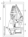
- FIG. 1 is a block diagram showing a configuration of an information processing system 1 according to the present embodiment.
- the information processing system 1 includes a gateway 10, a server 20, and a terminal 30.
- the server 20 is an example of the information processing device in the present invention.
- the gateway 10 is installed in the manufacturing facility 90 including the manufacturing line 9, and collects information on the state of each facility Mi.
- the server 20 is connected to the gateway 10 via a WAN (Wide Area Network) 1001 and receives information on the status of each facility Mi via the gateway 10.
- the terminal 30 is connected to the server 20 via WAN1001 and displays information about each facility Mi provided by the server 20.
- the terminal 30 may be a notebook computer, a smartphone, a tablet, or the like carried by a person in charge of maintenance of each facility Mi.
- the terminal 30 may be installed in a support sensor corresponding to maintenance of the production line 9.
- the terminal 30 may be installed in the manufacturing facility 90 for use by the person in charge at the site of the manufacturing line 9. Further, although FIG.
- the information processing system 1 may include a plurality of terminals 30.
- one of the plurality of terminals 30 may be carried by the person in charge described above, one may be set in the support center described above, and any other may be installed in the manufacturing facility 90. ..
- the production line 9 is, for example, a line for producing a mold or the like, but is not limited thereto.
- Each facility Mi has a built-in controller Pi.
- the equipment Mi is, for example, a molding machine, a blasting device, a dust collector, or the like, but is not limited thereto.
- Each controller Pi controls the equipment Mi.
- the controller Pi is a PLC (Programmable Logic Controller) controller that operates according to a program that controls each part of the equipment Mi.
- Each controller Pi acquires information representing the internal state of the equipment Mi.
- the information representing the internal state is, for example, the power state of the equipment Mi, the standby state, the information indicating the number of times the inspection process of the predetermined part is performed, the operating time of the predetermined part, the replacement date and time of the predetermined part, and the predetermined work.
- the information representing the internal state is not limited to these.
- each controller Pi is connected to a gateway 10 described later via a LAN (Local Area Network) 9001 laid in the manufacturing facility 90.
- the LAN 9001 is composed of a wired LAN, a wireless LAN, or a combination thereof.
- Each controller Pi transmits the requested information to the gateway 10 in response to the request from the gateway 10.
- Each sensor Cj is attached to at least one of the facilities M1 to Mn.
- incidental means that it is retrofitted to the equipment Mi in order to measure the external state of the equipment Mi.
- the installation location of the sensor Cj itself may be inside or outside the equipment Mi.
- the number of sensors Cj attached to one facility Mi is not limited to one, and may be plural.
- sensors C1 and C2 are attached to the equipment M1.
- the sensor C3 is attached to the equipment M2.
- a sensor Cm is attached to the equipment Mn.
- Each sensor Cj acquires information representing the external state of the equipment Mi.
- the information representing the external state there is information representing the vibration of the equipment Mi.
- the temperature of hot water injected into the equipment Mi can be mentioned.
- the sensor Cj is, for example, a vibration sensor, a CT (Current Transformer) sensor, a manometer, an oil deterioration sensor, a non-contact temperature sensor, and the like, but is not limited thereto.
- each sensor Cj is communicably connected to the sensor master unit CP.
- each sensor Cj and the sensor master unit CP are connected via a wireless sensor network.
- the wireless sensor network is constructed by short-range wireless communication such as infrared rays and Bluetooth (registered trademark).
- information is transmitted and received between the sensor master unit CP and the sensor Cj according to a predetermined protocol.
- the sensor Cj has a communication interface connected to the corresponding wireless sensor network by the sensor master CP and transmits / receives information according to the corresponding protocol of the sensor master CP, it is attached to any equipment Mi. It can be easily added as a retrofit.
- the sensor Cj may be of a type that periodically measures information and transmits it to the sensor master unit CP. Further, the sensor Cj may be of a type that is transmitted to the sensor master unit CP when information satisfying a predetermined condition is measured. Further, the sensor Cj may be of a type that transmits the information measured in response to the request from the sensor master unit CP to the sensor master unit CP.
- the sensor master unit CP receives information indicating the external state of the equipment Mi measured by each sensor Cj.
- the timing at which the sensor master unit CP receives information from the sensor Cj is the timing according to the type of the sensor Cj described above.
- the sensor master unit CP stores the information received from each sensor Cj in the memory (not shown) of the sensor master unit CP in association with the identification information of the sensor Cj.
- the sensor master unit CP is connected to the gateway 10 via LAN9001.
- the sensor master unit CP reads the requested information measured by the sensor Cj from the memory and transmits it to the gateway 10.
- the information to be transmitted is the information measured by the sensor Cj from the previous request from the gateway 10 to the request from the current gateway 10.
- the production line 9 has one sensor master unit CP, but may include a plurality of sensor master units configured in the same manner as the sensor master unit CP.
- each sensor Cj is connected to any of a plurality of sensor master units.
- at least one of the plurality of sensor master units may be connected to a wireless sensor network different from that of the other at least one sensor master unit.
- at least one of the plurality of sensor master units may communicate with each sensor Cj using a protocol different from that of the other at least one sensor master unit.
- FIG. 2 is a block diagram showing a hardware configuration of the gateway 10.
- the gateway 10 is composed of a computer having a processor 101, a main memory 102, an auxiliary memory 103, a communication interface 104, and a communication interface 105.
- the main memory 102 and the auxiliary memory 103 are examples of the memories included in the gateway in the present invention.
- the communication interface 104 is an example of the communication interface provided in the gateway for communicating with the controller and the communication interface for communicating with the sensor without going through the controller in the present invention.
- the communication interface 105 is an example of the communication interface for communicating with the sensor provided in the gateway in the present invention.
- the processor 101, the main memory 102, the auxiliary memory 103, the communication interface 104, and the communication interface 105 are connected to each other via the bus 109.
- the processor 101 for example, a single or a plurality of microprocessors, a single or a plurality of digital signal processors, a single or a plurality of microcontrollers, or a combination thereof is used.
- the main memory 102 for example, a single or a plurality of semiconductor RAMs (random access memory) are used.
- the auxiliary memory 103 for example, a single or a plurality of HDDs (Hard Disk Drive), a single or a plurality of SSDs (Solid State Drive), or a combination thereof is used.
- auxiliary memory 103 may be storage on a network connected via the communication interface 104 or 105.
- the communication interface 104 connects to WAN1001 such as the Internet.
- the communication interface 105 connects to a wired or wireless LAN 9001.
- the auxiliary memory 103 stores a program P10 for causing the processor 101 to execute the process S10 of the gateway 10 described later.
- the processor 101 expands the program P10 stored in the auxiliary memory 103 on the main memory 102, and executes each instruction included in the program P10 expanded on the main memory 102 to execute each step included in the process S10. To execute. Further, the auxiliary memory 103 stores various data referred to by the processor 101 in order to execute the process S10.
- the present invention is not limited to this.
- a mode in which the processor 101 executes the process S10 according to the program P10 stored in the external recording medium may be adopted.
- the external recording medium a computer-readable "non-temporary tangible medium” such as a tape, a disk, a card, a semiconductor memory, or a programmable logic circuit can be used.
- a mode may be adopted in which the processor 101 executes the process S10 according to the program P10 acquired from the network connected via the communication interface 104 or 105.
- the present invention is not limited to this. That is, a mode may be adopted in which the gateway 10 is realized by using a plurality of computers configured to be able to communicate with each other. In this case, each step constituting the process S10 can be executed in parallel by these computers.
- the gateway 10 has a function of acquiring information representing the internal state of the equipment Mi from each controller Pi. Therefore, the gateway 10 transmits / receives information to / from the controller Pi according to the connection protocol corresponding to each controller Pi.
- the gateway 10 has a function of acquiring information representing the external state of the equipment Mi from each sensor Cj. Therefore, the gateway 10 transmits / receives information to / from the sensor master CP according to the connection protocol supported by the sensor master CP.
- the gateway 10 has a function of acquiring information representing the internal state and the external state of the equipment Mi from each controller Pi and each sensor Cj, and transmitting the acquired information to the server 20.
- the acquisition of such information is collected.
- the collection process is executed according to the collection setting data described later.
- the gateway 10 stores the collection setting data in the auxiliary memory 103.
- the collection setting data is received from the server 20. Details of the collection setting data will be described later.
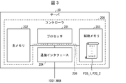
- FIG. 3 is a block diagram showing a hardware configuration of the server 20.
- the server 20 is composed of a computer including a controller 200 and a communication interface 204.
- the controller 200 includes a processor 201, a main memory 202, and an auxiliary memory 203.
- the main memory 202 and the auxiliary memory 203 are examples of the memories provided in the server in the present invention.
- the communication interface 204 is an example of the communication interface provided in the server in the present invention.
- the processor 201, the main memory 202, the auxiliary memory 203, and the communication interface 204 are connected to each other via the bus 209.
- the processor 201 for example, a single or a plurality of microprocessors, a single or a plurality of digital signal processors, a single or a plurality of microcontrollers, or a combination thereof is used.
- the main memory 202 for example, a single or a plurality of semiconductor RAMs are used.
- the auxiliary memory 203 for example, a single or a plurality of HDDs, a single or a plurality of SSDs, or a combination thereof is used. Further, a part or all of the auxiliary memory 203 may be storage on the network connected via the communication interface 204.
- the communication interface 204 connects to the WAN 1001.
- the auxiliary memory 203 stores programs P20_1 and P20_2 for causing the processor 201 to execute the processes S20_1 and S20_2 of the server 20, which will be described later.
- the processor 201 expands the programs P20_1 and P20_2 stored in the auxiliary memory 203 on the main memory 202, and executes each instruction included in the programs P20_1 and P20_2 expanded on the main memory 202. As a result, the processor 201 executes each step included in the processes S20_1 and S20_2.
- the auxiliary memory 203 stores various data referred to by the processor 201 in order to execute the processes S20_1 and S20_1.
- the communication interface 204 is connected to the gateway 10 and the terminal 30 via WAN1001.
- the present invention is not limited to this. That is, a mode may be adopted in which the processor 201 executes the processes S20_1 and S20_2 according to the programs P20_1 and P20_2 stored in the external recording medium.
- a mode may be adopted in which the processor 201 executes the processes S20_1 and S20_2 according to the programs P20_1 and P20_2 stored in the external recording medium.
- the external recording medium a computer-readable "non-temporary tangible medium" such as a tape, a disk, a card, a semiconductor memory, or a programmable logic circuit can be used.
- a mode may be adopted in which the processor 201 executes the processes S20_1 and S20_2 according to the programs P20_1 and P20_2 acquired from the network connected via the communication interface 204.
- the present invention is not limited to this. That is, a mode may be adopted in which the server 20 is realized by using a plurality of computers configured to be able to communicate with each other. In this case, the steps constituting the processes S20_1 and S20_2 can be executed in parallel by these computers.
- the server 20 has a function of accumulating the information representing the internal state and the information representing the external state collected for each facility Mi.
- the server 20 has a function of integrating and outputting information representing the internal state and information representing the external state of each facility Mi.
- the integrated output may be to output statistical information regarding information representing the internal state of the equipment Mi and information representing the external state. Further, the integrated output may mean that the information indicating the internal state and the information indicating the external state of the equipment Mi are output so as to be included in the same screen. As an example of integrated output, it is possible to output the total number of alarm outputs based on the information indicating the internal state of the equipment Mi and the total number of alarm outputs based on the information representing the external state.
- integrated output it is possible to superimpose and display graphs showing the time changes of the information representing the internal state and the information representing the external state of the equipment Mi on a common time axis. Further, as another example of integrated output, information representing the internal state of the equipment Mi and information representing the external state are superimposed on the external image of the equipment Mi at the positions corresponding to each state. Can be mentioned. Specific examples of these examples will be described later.
- the server 20 has a function of outputting a tendency to output a maintenance alarm described later and a tendency to output a facility alarm described later for each facility Mi.
- the maintenance alarm or equipment alarm may be output to an output device, or may be output to a predetermined contact address (for example, an e-mail address, a telephone number, etc.) by a predetermined communication means (for example, a telephone number). , E-mail, telephone, facsimile, etc.).
- the tendency of each alarm to be output is represented by, for example, statistical information such as the total number of output times, a time change of a physical quantity causing the alarm to be output, and the like, but is not limited thereto.
- the tendency of the alarm to be output is also described as the tendency of the alarm to occur.
- the server 20 has a function of acquiring collection setting data indicating what kind of internal state information and external state information are to be collected for each facility Mi.
- the server 20 has a function of acquiring alarm setting data for each equipment Mi, which is associated with a determination condition for determining the state of the equipment Mi and a type indicating either a maintenance alarm or an equipment alarm.
- the judgment condition associated with the type "maintenance alarm” is also described as the judgment condition of the maintenance alarm.
- the determination condition of the maintenance alarm corresponds to the first condition in the present invention.
- the judgment condition associated with the type "equipment alarm” is also described as the judgment condition of the equipment alarm.
- the equipment alarm determination condition corresponds to the second condition in the present invention.
- the maintenance alarm is an alarm that prompts maintenance of the equipment Mi.
- the maintenance alarm corresponds to the first alarm in the present invention.
- the maintenance alarm indicates that maintenance that is not related to equipment abnormalities is recommended. Examples of maintenance that are not related to equipment abnormalities include, but are not limited to, adjustment and replacement of parts and replenishment of consumables.
- the maintenance alarm serves as a signal to maintain the equipment Mi.
- the maintenance alarm indicating that the liner usage time has exceeded the threshold value is an alarm for prompting the liner to be inspected or replaced.
- the maintenance alarm indicating that the remaining amount of consumables has fallen below the threshold value is an alarm for prompting the replenishment of consumables.
- the maintenance alarm indicating that the cycle of the lubrication oil for the bearing has exceeded the threshold value is an alarm for prompting inspection or lubrication oil.
- the maintenance alarm indicating that the tendency of the load current value of the motor is abnormal is an alarm for prompting inspection or replacement of the motor.
- a condition for judging whether or not the state of the equipment Mi is a state in which maintenance is recommended is defined.
- Examples of the judgment condition of the maintenance alarm include, but are not limited to, the elapsed operation time exceeds the threshold value, the sensor value indicating the remaining amount of consumables falls below the threshold value, and the like.
- the maintenance alarm may be output in stages according to the need for maintenance.
- the determination condition of the maintenance alarm may be determined step by step according to the need for maintenance.
- the number of stages of the maintenance alarm may be 1 (in other words, no stage is set) or may be a plurality of stages.
- the maintenance alarm may be output at a predetermined timing regardless of whether or not the judgment condition of the maintenance alarm is satisfied.
- the predetermined timing include a timing based on a predetermined schedule, a periodic timing, a timing instructed by an input operation, and the like. For example, by periodically outputting a maintenance alarm, the user can be urged to perform regular maintenance. In addition, the maintenance alarm is output at the timing instructed by the input operation, so that the user can be urged to perform temporary maintenance.
- the equipment alarm is an alarm indicating the occurrence or a sign of an abnormality in the equipment Mi.
- the equipment alarm corresponds to the second alarm in the present invention.
- the equipment Mi has a function of stopping the equipment Mi so as not to cause a failure when an event indicating an abnormality occurs in the equipment Mi.
- the equipment alarm indicates that such equipment Mi has stopped (abnormality) or that an event leading to the stop has occurred (predictive).
- the equipment alarm has a role of notifying the occurrence of an abnormality in the equipment Mi or a role of notifying a warning at a stage before the occurrence of an abnormality.
- a foreign object removal or motor replacement is required due to an equipment alarm that indicates a motor thermal trip abnormality or a sign thereof.
- foreign matter removal or lubrication is required due to an equipment alarm that indicates an abnormality in the rising end of the cylinder or a sign thereof.
- the filter needs to be replaced due to an equipment alarm indicating an abnormality in the filter or a sign thereof.
- the condition for judging that the state of the equipment Mi indicates an abnormality or a sign of an abnormality is defined.
- the temperature of a predetermined part of the equipment Mi exceeds (or falls below) the threshold value
- the flow rate of the fluid flowing inside the equipment Mi exceeds (or falls below) the threshold value, and the like. Not limited to these.
- the server 20 outputs the equipment alarm and stores it in the auxiliary memory 203.
- the equipment alarm may be output in stages according to the possibility that an abnormality may occur in the equipment. For example, when the physical quantity indicating an abnormality of the equipment Mi exceeds the threshold value ⁇ 1, it is assumed that the equipment Mi is stopped. In this case, it is assumed that the condition that the physical quantity exceeds ⁇ 1 and the condition that the physical quantity exceeds ⁇ 2, which is smaller than ⁇ 1, are defined as the judgment conditions of the equipment alarm. At this time, the equipment alarm output when the physical quantity exceeds the threshold value ⁇ 2 indicates a sign of abnormality of the equipment Mi. Further, the equipment alarm output when the physical quantity exceeds the threshold value ⁇ 1 indicates an abnormality of the equipment Mi.
- the number of stages of the equipment alarm may be 1 (in other words, no stage is set) or may be a plurality of stages.
- the server 20 stores the configuration data, the collection setting data, and the alarm setting data related to the configuration of the production line 9 in the auxiliary memory 203. Details of the collection setting data and the alarm setting data will be described later. Here, a specific example of the configuration data will be described.
- FIG. 4 is a diagram showing an example of configuration data of the production line 9.
- the configuration data includes information about each facility Mi and information about each sensor Cj.
- Each line shown in FIG. 4A represents information about the equipment Mi.
- the information about each equipment Mi includes the identification information "equipment name" of the equipment Mi, the network address of the built-in controller Pi, the connection protocol supported by the controller Pi, and the identification information "part name” of the parts of the equipment Mi. And the identification information of the related file 1 and the related file 2.
- the network address of the controller Pi built in the equipment M1 is "address 1”
- the corresponding connection protocol is "protocol A”.
- the equipment M1 includes a part A and a part B.
- the manual A is registered as the related file 1 of the equipment M1
- the appearance image A is registered as the related file 2.
- Each line shown in FIG. 4B represents information about the sensor Cj.
- the information about each sensor Cj includes the identification information "sensor name" of the sensor Cj, the network address of the sensor master unit CP to which the sensor Cj is connected, and the connection protocol corresponding to the sensor master unit CP.
- the sensor C1 is connected to the sensor master unit CP having the network address “address 10”.
- the connection protocol supported by the sensor master CP is "protocol C".
- configuration data of the production line 9 is not limited to the information shown in FIGS. 4A and 4B, and may include other information.
- FIG. 5 is a block diagram showing a hardware configuration of the terminal 30.
- the terminal 30 is composed of a computer having a processor 301, a main memory 302, an auxiliary memory 303, a communication interface 304, and an input / output interface 305.
- the processor 301, the main memory 302, the auxiliary memory 303, the communication interface 304, and the input / output interface 305 are connected to each other via the bus 309.
- the processor 301 for example, a single or a plurality of microprocessors, a single or a plurality of digital signal processors, a single or a plurality of microcontrollers, or a combination thereof is used.
- the main memory 302 for example, a single or a plurality of semiconductor RAMs are used.
- the auxiliary memory 303 for example, a single or a plurality of HDDs, a single or a plurality of SSDs, or a combination thereof is used.
- auxiliary memory 303 may be storage on the network connected via the communication interface 304 or 305.
- the communication interface 304 connects to WAN1001.
- a USB (Universal Serial Bus) interface for example, a USB (Universal Serial Bus) interface, a short-range communication interface such as infrared rays or Bluetooth (registered trademark), or a combination thereof is used.
- An input device 310 and an output device 320 are connected to the input / output interface 305.
- the input device 310 for example, a keyboard, a mouse, a touch pad, a microphone, or a combination thereof or the like is used.
- the output device 320 for example, a display, a printer, a speaker, or a combination thereof is used.
- the terminal 30 may include a keyboard and a touch pad that function as an input device 310, and a display that functions as an output device 320, such as a notebook computer. Further, the terminal 30 may have a built-in touch panel that functions as an input device 310 and an output device 320, such as a smartphone and a tablet.
- the auxiliary memory 303 stores a program P30 for causing the processor 301 to execute the processing of the terminal 30.
- the processor 301 expands the program P30 stored in the auxiliary memory 303 on the main memory 302, and executes each instruction included in the program P30 expanded on the main memory 302. Further, the auxiliary memory 303 stores various data referred to by the processor 301 in order to execute the processing of the terminal 30.
- the present invention is not limited to this.
- a mode in which the processor 301 operates according to the program P30 stored in the external recording medium may be adopted.
- the external recording medium a computer-readable "non-temporary tangible medium” such as a tape, a disk, a card, a semiconductor memory, or a programmable logic circuit can be used.
- a mode in which the processor 301 operates according to the program P30 acquired from the network connected via the communication interface 304 or 305 may be adopted.
- the present invention is not limited to this. That is, a form may be adopted in which the terminal 30 is realized by using a plurality of computers configured to be able to communicate with each other.
- the terminal 30 has a function of receiving information from the server 20 in which information representing the internal state of the equipment Mi and information representing the external state are integrated and outputting the information to the output device 320. Further, the terminal 30 has a function of acquiring information for setting the collection setting data and the alarm setting data from the input device 310 and transmitting the information to the server 20.
- FIG. 6 is a flowchart illustrating a flow of processing in which the information processing system 1 collects information representing the state of each facility Mi, integrates and displays the information.
- the left figure shows the server process S20_1
- the right figure shows the gateway process S10
- the broken line arrow connecting the left and right shows the data flow.
- the server 20 executes a process of acquiring collection setting data.
- the collection setting data includes identification information of information representing an internal state to be received from the controller Pi and timing for receiving the information.
- the collection setting data includes identification information of information representing an external state to be received from the sensor Cj and timing for acquiring the information.
- the timing to be acquired is represented by information representing a predetermined interval such as a 1-second interval, a 10-second interval, or the like.
- the collection setting data is set based on the information input by the user.
- the server 20 transmits the setting screen of the collection setting data to the terminal 30, and the terminal 30 displays the setting screen on the display as the output device 320.
- the terminal 30 transmits the information input to the setting screen via the input device 310 to the server 20, and the server 20 acquires the collection setting data based on the received information. Details of the collection setting data and a specific example of the setting screen will be described later.
- step S102 the server 20 transmits the collection setting data to the gateway 10.
- step S103 the gateway 10 stores the received collection setting data in the auxiliary memory 103.
- step S104 the server 20 transmits information instructing the start of collection to the gateway 10.
- the gateway 10 starts collecting information from each controller Pi and each sensor Cj according to the collection setting data.
- step S105 the gateway 10 receives information indicating the internal state of the equipment Mi acquired by the controller Pi from each controller Pi according to the collection setting data.
- the received information is stored in the auxiliary memory 103 in association with the reception date and time. Details of the processing in this step will be described later.
- step S106 the gateway 10 receives information representing the external state of the equipment Mi measured by each sensor Cj via the sensor master unit CP according to the collection setting data.
- the received information is stored in the auxiliary memory 103 in association with the reception date and time. Details of the processing in this step will be described later.
- step S107 the gateway 10 determines whether or not it is time to transmit the information representing the internal state and the information representing the external state of each facility Mi to the server 20. For example, the gateway 10 may determine that the timing is when a predetermined period (for example, 1 minute, 5 minutes, etc.) has elapsed from the timing of the previous transmission. Further, for example, the gateway 10 may determine that the timing is when the capacity of the information stored in the auxiliary memory 103 in steps S105 and S106 exceeds a predetermined amount after the previous transmission timing. In addition, the gateway 10 may determine that it is the timing when other conditions are satisfied. If No in step S107, the process from step S105 is repeated. If Yes in step S107, the process of the next step S108 is executed.
- a predetermined period for example, 1 minute, 5 minutes, etc.
- step S108 the gateway 10 executes a process of transmitting information representing the internal state and information representing the external state of each facility Mi to the server 20.
- the information to be transmitted is the information stored in the auxiliary memory 103 in steps S105 and S106 after the processing of the step was executed last time.
- step S109 the server 20 stores the information representing the internal state and the information representing the external state of each facility Mi received from the gateway 10 in the auxiliary memory 203 in association with the reception date and time.
- step S110 the server 20 executes a process of integrating and outputting the information representing the internal state and the information representing the external state stored in the auxiliary memory 203 for each facility Mi.
- the server 20 may integrate the information representing the internal state and the information representing the external state stored in the auxiliary memory 203 based on the reception date and time.
- the processing to output is mentioned.
- the example of integration based on the reception date and time is not limited to these.
- step S110 does not have to be continuously executed each time step S109 is executed. Specifically, the process of step S109 is executed each time information representing the internal state and information representing the external state of each facility Mi is received from the gateway 10. As a result, information representing the internal state and information representing the external state of each facility Mi is stored in the auxiliary memory 203. Further, the process of step S110 is executed at a predetermined timing based on the information stored in the auxiliary memory 203.
- the predetermined timing may be, for example, a predetermined interval (for example, every 5 minutes), a timing requested by the terminal 30, or a timing satisfying other conditions. ..
- step S111 the server 20 determines whether or not to stop the collection based on whether or not the condition for stopping the collection is satisfied. For example, when the server 20 receives the information requesting the resetting of the collection setting data from the terminal 30, it determines that the collection is stopped. Further, when the server 20 receives the information that the production line 9 is not operating, the server 20 determines that the collection is stopped. If No in step S111, the process from step S109 is repeated. If Yes in step S111, the process of the next step S112 is executed.
- step S112 the server 20 transmits information instructing the stop of collection to the gateway 10.
- step S113 the gateway 10 determines whether or not the information instructing the stop of collection has been received. If No in step S113, the gateway 10 repeats the process from step S105. If Yes in step S113, the gateway 10 repeats the process from step S103.
- the setting screen of the collection setting data displayed in step S101 will be described with reference to a specific example.
- the setting screen G1 is a screen that accepts settings related to information representing an internal state.
- the setting screen G2 is a screen that accepts settings related to information representing an external state.
- each of the information representing the internal state and the information representing the external state to be collected for the n equipment Mi is identified by the identification information called "tag".
- the data collected for the information identified by the tag will also be referred to as the collected data of the tag.
- FIG. 7A is a diagram showing an example of the setting screen G1.
- the setting screen G1 includes fields G101 to G106 in which equipment names, tag names, device names, unit conversions, units, and collection cycles can be input, registration buttons G111, and back buttons G112.
- each field G101 to G106 may be accompanied by an input support function such as display of a selection list and restriction of input character types.
- the equipment name field G101 is a UI object into which the identification information of any equipment Mi included in the configuration data of the production line 9 is input.
- the controller Pi that should collect the information indicating the internal state is specified by inputting the identification information of the equipment Mi. ..
- the tag name field G102 is a UI object into which the identification information of the information collected from the equipment Mi is input.
- the device name field G103 is a UI object in which the device identification information in which the information representing the internal state is stored is input in the controller Pi.
- the unit conversion field G104 is a UI object into which a conversion rule for converting a unit of information collected from the device into another unit is input.
- the conversion rule is expressed by, for example, a calculation formula.
- the unit field G105 is a UI object into which information representing the unit after the unit is converted according to the conversion rule is input.
- the collection cycle field G106 is a UI object in which the cycle for collecting information representing the internal state is input.
- the collection cycle may be input in units of seconds, minutes, hours, and the like.
- the setting screen G1 is transmitted from the server 20 to the terminal 30 according to the request from the terminal 30, and is displayed on the display as the output device 320.
- the information input from the input device 310 on the setting screen G1 is transmitted from the terminal 30 to the server 20 in response to the operation for the registration button G111, and is stored in the auxiliary memory 203 as setting data of the information indicating the internal state. Will be done.
- the collection setting data transmitted from the server 20 to the gateway 10 is generated.
- the display of the setting screen G1 ends without the information input on the setting screen G1 being transmitted to the server 20.
- FIG. 7B is a diagram showing an example of setting data of information representing an internal state stored in the auxiliary memory 203.
- the information set in association with the identification information "tag T11" is as follows. That is, the set information collects the value stored in the device "data register D01" from the controller P1 built in the equipment M1 in the collection cycle of 30 seconds, and the collected value is unit-converted by the calculation formula 1. It means that the value is expressed in the unit 1.
- the tags T12, T13, and T14 will be described in the same manner.
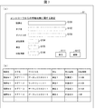
- FIG. 8A is a diagram showing an example of the setting screen G2.
- the setting screen G2 includes fields G201 to G206 in which equipment names, tag names, sensor names, unit conversions, units, and collection cycles can be input, registration buttons G211 and back buttons G212. Similar to the setting screen G1, the above-mentioned input support functions may be attached to the fields G201 to G206.
- the equipment name, tag name, unit conversion, unit and collection cycle fields G201 to G202 and G204 to G206 are the same as the fields with the same name included in the setting screen G1, so description thereof will be omitted.
- the sensor name field G203 is a UI object into which the identification information of any sensor Cj included in the configuration data of the manufacturing line 9 is input.
- the sensor Cj is registered as attached to the equipment Mi.
- the setting screen G2 is transmitted from the server 20 to the terminal 30 according to the request from the terminal 30, and is displayed on the display as the output device 320.
- the information input from the input device 310 on the setting screen G2 is transmitted from the terminal 30 to the server 20 in response to the operation for the registration button G211 and stored in the auxiliary memory 203 as setting data of the information indicating the external state. Will be done.
- the collection setting data transmitted from the server 20 to the gateway 10 is generated.
- the display of the setting screen G1 ends without the information input on the setting screen G1 being transmitted to the server 20.
- FIG. 8B is a diagram showing an example of setting data of information representing an external state stored in the auxiliary memory 203.
- the value measured by the “sensor C1” attached to the equipment M1 in association with the identification information “tag T21” is collected in a collection cycle of 1 second, and the collected value is unit-converted by the calculation formula 4. It is set to be a value represented by the unit 4.
- the tags T22 and T23 will be described in the same manner.
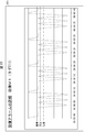
- FIG. 9 is a diagram showing a specific example of the collection setting data transmitted from the server 20 to the gateway 10 in step S102.
- the collection setting data includes information on a tag name, a network address, a device name or a sensor name, a connection protocol, a unit conversion, and a collection cycle.
- the collection setting data is generated based on the setting data shown in FIGS. 7 (b) and 8 (b), respectively.
- the setting data shown in FIGS. 7 (b) and 8 (b) are required for information required for collection processing such as "network address" and for display processing such as "unit". Information is included. Therefore, the server 20 extracts the information necessary for the collection process from the setting data shown in FIGS. 7B and 8B, generates the collection setting data shown in FIG. 9, and transmits the collection setting data to the gateway 10. To do.
- the gateway 10 communicates with the controller Pi at address 1 by protocol A according to the first line of the collection setting data, and collects the information of the data register D01 every 30 seconds. Then, the gateway 10 stores the collected information in the auxiliary memory 103 as the collected data of the tag T11 by converting the collected information into units by the calculation formula 1 in association with the collection date and time. Similarly, the gateway 10 stores the collected data of the tags T12 to T14 and T21 to T23 and the collection date and time in the auxiliary memory 103. Then, the gateway 10 transmits the collected data of the tags T11 to T14 and T21 to T23 stored in the auxiliary memory 103 and the collection date and time to the server 20 at a predetermined transmission timing.
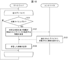
- FIG. 10 is a flowchart showing a specific example of a detailed flow of the process of collecting information representing the internal state in step S105.
- the left figure shows the operation of the gateway 10
- the right figure shows the operation of the controller Pi.
- the broken line arrow connecting the left and right indicates the data flow.
- the gateway 10 executes the operations of steps S131 to S134 for each tag associated with the network address of the controller Pi among the collection setting data received from the server 20.
- step S131 the gateway 10 refers to the collection setting data and determines whether or not the collection cycle is associated with the tag. If No in step S131, the process related to the tag is terminated. If Yes in step S131, the process of the next step S132 is executed.
- step S132 the gateway 10 refers to the collection setting data and transmits the information specifying the device in which the information representing the internal state of the equipment Mi is stored to the controller Pi of the corresponding network address.
- step S133 the data stored in the designated device is read and transmitted to the gateway 10.
- step S134 the gateway 10 stores the received information in the auxiliary memory 103 in association with the identification information of the tag and the collection date and time.
- the gateway 10 repeats the processing of steps S131 to S134 for each corresponding tag again.
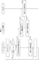
- FIG. 11 is a flowchart showing a specific example of a detailed flow of the process of collecting information representing the external state in step S106.
- the left figure shows the operation of the gateway 10
- the center figure shows the operation of the sensor master unit CP
- the right figure shows the operation of the sensor.
- the broken line arrow connecting the left and right indicates the data flow.
- the gateway 10 executes the operations of steps S141 to S146 for each tag associated with the network address of the sensor master unit CP among the collection setting data received from the server 20.
- step S141 the gateway 10 refers to the collection setting data and determines whether or not the collection cycle is associated with the tag. If No in step S141, the process related to the tag is terminated. If Yes in step S141, the process of the next step S142 is executed.
- step S142 the gateway 10 requests the sensor master unit CP with the information measured by the sensor Cj indicated by the tag as the information indicating the external state of the equipment Mi.
- step S143 the sensor master unit CP requests the measured information from the requested sensor Cj.
- the process of this step is executed when the corresponding sensor Cj is a type that transmits the measured information in response to the request from the sensor master unit CP.
- the corresponding sensor Cj is a type that measures information at predetermined intervals and transmits it to the sensor master unit CP, or a type that measures information that satisfies a predetermined condition and transmits it to the sensor master unit CP, the process of this step. Is omitted.
- step S144 the sensor Cj transmits the measured information to the sensor master unit CP.
- the process of this step is executed in response to the request in step S143 when the corresponding sensor Cj is of a type that transmits the information measured in response to the request from the sensor master unit CP.
- the corresponding sensor Cj is a type that measures information at predetermined intervals and transmits it to the sensor master unit CP, or a type that measures information that satisfies a predetermined condition and transmits it to the sensor master unit CP
- the process of this step. Is executed at any time at each applicable timing. Further, in this case, the measured information is stored in the memory of the sensor master unit CP.
- step S145 the sensor master unit CP transmits the information measured by the sensor Cj to the gateway 10.
- step S146 the gateway 10 stores the received information in the auxiliary memory 103 in association with the identification information of the tag and the collection date and time.
- the gateway 10 repeats the processing of steps S141 to S146 for each corresponding tag again.
- step S110 a specific example of the screen displayed on the display as the output device 320 will be described.
- 12 to 16 are diagrams showing specific examples of screens in which information representing an internal state and information representing an external state are integrated for each facility Mi.
- the information in which the information representing the internal state and the information representing the external state are integrated will be simply referred to as the integrated information.
- FIG. 12 is a diagram showing the main screen G3, and includes integrated information regarding each of the plurality of equipment Mi.
- the main screen G3 allows the user to list integrated information for each of the plurality of equipment Mi.
- the main screen G3 includes an area G301a, an area G301b, an area G301c, and an area G301d.
- Area G301a contains integrated information about equipment M1.
- Area G301b contains integrated information about equipment M2.
- Area G301c contains integrated information about equipment M3.
- Area G301d contains integrated information about equipment M4.
- Area G301a includes a tag area G302a, an operating state area G303a, an equipment alarm area G304a, a maintenance alarm area G305a, and a button G306a.
- Each of the areas G301b to G301d includes a tag area G302b to G302d, an operating state area G303b to G303d, an equipment alarm area G304b to G304d, a maintenance alarm area G305b to G305d, and a button G306b to G306d, similarly to the area G301a.
- G301 to G306 when it is not necessary to particularly distinguish the reference numerals G301 to G306 having any of a to d as subscripts, they are also simply referred to as G301 to G306.
- the tag area G302 is an area in which the collected data of any of the tags collected for the corresponding equipment Mi is displayed.
- the collected data of 67.8 (° C.) is displayed for the tag T11. That is, the tag displayed in the tag area G302 is a tag representing the information representing the internal state of the equipment Mi or a tag representing the information representing the external state.
- the tag area G302 includes a button G306 for selecting another tag.
- the collected data of other tags collected for the corresponding equipment Mi is displayed.
- the selection list of the tags collected for the equipment M4 is displayed by accepting the operation for the button G306d for the equipment M4.
- the display content of the tag area G302d is changed to the collected data of the selected tag.
- the operating status area G303 is an area in which the operating status of the corresponding equipment Mi is displayed.
- the operating status is displayed based on the history of tags representing the operating status of the equipment Mi collected for the equipment Mi.
- the collected data of the tag representing the operating state of the equipment Mi indicates any of "operating", "standby", “abnormal", and "stopped”.
- the tag representing the operating state is information representing the internal state collected from the controller Pi.
- the operating state area G303 includes an indication of the percentage of each operating state.
- the ratio of each operating state may be a ratio of the total operating hours in a predetermined period.
- the predetermined period may be one day, one week, one month, etc., but is not limited thereto.
- the equipment alarm area G304 is an area where the tendency of equipment alarms to occur is displayed.
- the occurrence tendency is represented by the number of times that the collected data of one or a plurality of tags representing the state of the equipment Mi satisfies the determination condition of the equipment alarm, that is, the total number of occurrences of the equipment alarm for each urgency.
- the total number of times may be reset to the initial value at a predetermined time point.
- the predetermined time point may be, but is not limited to, a day, a week, a start time of a month, and the like.
- the occurrence tendency is not limited to the number of occurrences, and may be represented by other information such as the occurrence rate of each urgency.
- the tendency of occurrence may be graphically represented by a graph or the like.
- the equipment alarm area G304 includes information indicating that the equipment alarm is being generated for the equipment Mi when the latest collected data of any tag satisfies the determination condition of the equipment alarm. ..
- the equipment alarm area G304b of the equipment M2 it is displayed that the equipment alarm of the urgency "warning" is being generated for the tag T24 indicating the external state of the equipment M2. This indicates that the latest collected data of the tag T24 satisfies the determination condition of the urgency "warning" among the equipment alarms set for the tag T24.
- the maintenance alarm area G305 will be similarly explained by replacing the equipment alarm with the maintenance alarm in the description of the equipment alarm area G304.
- the maintenance alarm areas G305a, 305b, and 305d of the facilities M1, M2, and M4 display the total number of maintenance alarm occurrences for each degree of urgency.
- the maintenance alarm of the urgency "danger" is being generated for the tag T19 indicating the internal state of the equipment M3.
- the collected data of the tag representing the information representing the internal state of the equipment Mi or the tag representing the information representing the external state is displayed.
- the equipment alarm area G304 the occurrence tendency in which the number of times the equipment alarm determination conditions are satisfied for the tag indicating the internal state of the equipment Mi and the tag indicating the external state are integrated according to the degree of urgency is displayed. To. The same applies to the maintenance alarm area G305.
- the equipment alarm area G304 and the maintenance alarm area G305 include the following information as an example of the information "integrating the information representing the internal state and the information representing the external state" in the present invention. ..
- the information is the number of times the internal state is “abnormal” (or “warning", “caution") and the external state is “abnormal” (or “warning", “caution”). Represents the total number of times.
- the equipment alarm area G304 and the maintenance alarm area G305 include information representing the above total number as an example of "information in which alarms related to equipment are integrated" in the present invention.
- the maintenance alarm area G305 includes the total number of times the maintenance alarm is output as an example of the "tendency that the first alarm is output” in the present invention.
- the equipment alarm area G304 includes the total number of times the equipment alarm is output as an example of the "tendency to output the second alarm" in the present invention.
- FIG. 13 is a diagram showing the graphic monitor screen G4, which includes integrated information regarding the equipment M1.
- the user With the graphic monitor screen G4, the user collectively collects the positions where the information representing the internal state and the information representing the external state collected for any equipment Mi are acquired in the physical structure of the equipment Mi. Can be grasped.
- the graphic monitor screen G4 includes a selection button G401, an image G402, and tag labels G405a to G405d.
- the tag labels G405 are also simply described.
- Image G402 is an external image of equipment M1. The appearance image is registered in the configuration data shown in FIG.
- the tag label G405 is a label representing the collected data of tags related to the equipment M1.
- the tag label G405 is displayed superimposed on the image G402.
- the display position of the tag label G405 on the image G402 is stored in the auxiliary memory 203 in advance in association with the tag indicated by the tag label G405.
- the selection button G401 is a button for selecting the equipment Mi displayed on the graphic monitor screen G4.
- a list of equipment M1 to Mn is displayed as a selection list.
- the display content of the graphic monitor screen G4 is changed to the display content corresponding to the selected equipment Mi.
- the graphic monitor screen G4 represents the tags T11 and T12 corresponding to the information representing the internal state of the equipment M1 and the tags T21 and T22 corresponding to the information representing the external state of the equipment M1, respectively. Includes tag labels G405a-G405d. That is, the graphic monitor screen G4 includes information that represents the internal state of the equipment Mi and information that integrates information that represents the external state.
- FIG. 14 is a diagram showing the measured value monitor screen G5, and includes integrated information regarding the equipment M1. From the measured value monitor screen G5, the user can grasp the history of the information representing the internal state and the information representing the external state collected for any equipment Mi.
- the measured value monitor screen G5 includes a selection button G501 and a table G502.
- Table G502 shows the history of the collected data of the tags T11, T12, T21, and T22 related to the equipment M1.
- the selection button G501 is a button for selecting the equipment Mi displayed on the measurement value monitor screen G5. Since the details of the selection button G501 are the same as those of the selection button G401 described above, the detailed description will not be repeated.
- the measured value monitor screen G5 includes a history of tags T11 and T12 representing the internal state of the equipment M1 and tags T21 and T22 representing the information representing the external state of the equipment M1. .. That is, the measured value monitor screen G5 includes information that integrates information representing the internal state and information representing the external state of the equipment M1.
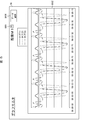
- FIG. 15 is a diagram showing the graph monitor screen G6, which includes integrated information regarding the equipment M1.
- the graph monitor screen G6 allows the user to graphically grasp the changes in the information representing the internal state and the information representing the external state collected for any equipment Mi.
- the graph monitor screen G6 includes a selection button G601, a graph area G602, and a data selection button G606.
- the graph area G602 includes a graph showing changes in the values of the tags T11, T21, and T22 related to the equipment M1.
- the horizontal axis of the graph represents the passage of time.
- the data selection button G606 is a button for selecting a tag to be displayed in the graph area G602.
- a list of tags related to the equipment M1 is displayed as a selection list.
- One or more tags can be selected from the selection list.
- the graph of the tags T11, T21, and T22 displayed in the graph area G602 is changed to the graph of the selected tag.
- the selection button G601 is a button for selecting the equipment Mi displayed on the graph monitor screen G6. Since the details of the selection button G601 are the same as those of the selection button G401 described above, the detailed description will not be repeated.
- the graph monitor screen G6 is a graph showing changes between the tag T11 representing the internal state of the equipment M1 and the tags T21 and T22 representing the information representing the external state of the equipment M1. including. That is, the graph monitor screen G6 includes information that integrates information that represents the internal state of the equipment M1 and information that represents the external state.
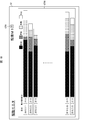
- FIG. 16 is a diagram showing an operation monitor screen G7, and includes information indicating an operation status of the equipment M1.
- the operation monitor screen G7 allows the user to graphically grasp the history of the operation status of any equipment Mi.
- the operation monitor screen G7 includes a selection button G701 and an operation status area G702.
- the operation status area G702 includes a bar graph showing the daily operation status of the equipment M1.
- the bar graph shows the ratio of the operating status "operating", “abnormal”, “standby”, and “stopped” on the date.
- the selection button G701 is a button for selecting the equipment Mi displayed on the operation monitor screen G7. Since the details of the selection button G701 are the same as those of the selection button G401 described above, the detailed description will not be repeated.
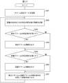
- FIG. 17 is a flowchart illustrating the flow of the process S20_2 in which the server 20 displays the occurrence tendency of the maintenance alarm and the equipment alarm.
- step S201 the server 20 acquires alarm setting data based on the information input by the user via the input device 310.
- the alarm setting data consists of an alarm rule that associates a judgment condition for determining the equipment status with a type indicating either a maintenance alarm or an equipment alarm.
- the alarm setting data is stored in the auxiliary memory 203.
- the judgment condition may be, but is not limited to, the collected data is equal to or higher than the threshold value, is lower than the threshold value, changes from on to off, changes from off to on, and the like. Further, the determination condition may further include that the number of consecutive determinations that the condition is satisfied exceeds the threshold value.
- step S202 the server 20 receives the collected data from the gateway 10 from the information representing the internal state of each facility Mi, the information representing the external state, or both.
- the process of this step is executed in response to the transmission process from the gateway 10 in step S108 shown in FIG.
- step S203 the server 20 refers to the alarm setting data and determines whether or not any of the received collected data satisfies the determination condition of the maintenance alarm. If No in step S203, the process of step S205 described later is executed. If Yes in step S203, the process of the next step S204 is executed.
- step S204 the server 20 outputs a maintenance alarm.
- the maintenance alarm includes, for example, a tag name, collected data satisfying the determination condition, and the content of the determination condition. Further, the server 20 stores the maintenance alarm in the auxiliary memory 203 in association with the collection date and time.
- step S205 the server 20 refers to the alarm setting data and determines whether or not any of the received collected data satisfies the determination condition of the equipment alarm. If No in step S205, the process of step S207 described later is executed. If Yes in step S205, the process of the next step S206 is executed.
- step S206 the server 20 outputs an equipment alarm.
- the equipment alarm includes, for example, a tag name, collected data satisfying the determination condition, and the content of the determination condition. Further, the server 20 stores the equipment alarm in the auxiliary memory 203 in association with the collection date and time.
- step S207 the server 20 outputs the maintenance alarm generation tendency and the equipment alarm generation tendency in a manner that can be distinguished and recognized for each equipment Mi based on the maintenance alarm and the equipment alarm stored in the auxiliary memory 203. To do.
- FIG. 18 is a diagram showing a specific example of the setting screen G8 displayed on the display as the output device 320 in step S201.
- the setting screen G8 accepts an input operation for setting an alarm rule regarding the equipment Mi.
- the setting screen G8 includes fields G801 and G802 in which equipment names and tag names can be input, areas G803 for setting rule types, areas G804a to G804c for setting judgment conditions, registration buttons G811, and a back button G812. including.
- up to three judgment conditions can be set for one tag, that is, information representing one type of internal or external state of each equipment Mi, but each tag can be set.
- the number of determination conditions may be 1 or 2, or 4 or more.
- the equipment name field G801 is a UI object into which the identification information of any equipment Mi included in the configuration data of the production line 9 is input.
- the tag name field G802 is a UI object into which any tag name included in the collection setting data is input.
- the area G803 for setting the rule type includes a set of radio buttons G803a for selecting the rule type and a field G803b for inputting a part name.
- the radio button G803a is a UI object that allows the user to select the type of equipment alarm or maintenance alarm.
- the part name field G803b is a UI object in which the part name related to the maintenance alarm is input when the maintenance alarm is selected as the rule type.
- the input part name is a part name registered as a part of the corresponding equipment Mi in the configuration data of the production line 9.
- the area G804a for setting the judgment condition is the first judgment condition No. related to the tag. Set to 1.
- the area G804a for setting the determination condition includes fields G805a and G806a in which the condition and the number of consecutive occurrences can be input, and drop-down lists G807a and G808a in which the urgency and the action can be selected, respectively.
- the condition field G805a is a UI object in which conditions related to the collected data of the corresponding tag are input. For example, when the collected data of the tag can take continuous values, a condition such as a threshold value or more or a threshold value or less can be input to the field G805a. Further, when the collected data of the tag has a binary value such as on or off, a condition such as a change from on to off or a change from off to on can be input to the field G805a. However, the information input to the field G805a is not limited to these.
- the field G806a of the number of consecutive occurrences is a UI object in which the threshold value of the number of times that the condition input to the field G805a is continuously satisfied (hereinafter, also referred to as the number of consecutive occurrences) is input.
- the determination condition of each alarm rule is determined by the server 20 at a predetermined timing.
- the predetermined timing may be, for example, the timing at which the collected data of each tag is received by the server 20, or may be at predetermined intervals.
- the urgency drop-down list G807a is a UI object that allows the urgency of the judgment condition to be selected.
- the maintenance alarm is selected as the rule type
- the operation drop-down list G808a is a UI object that selects a notification operation when the number of times the condition is satisfied exceeds the number of consecutive occurrences.
- e-mail notification When e-mail notification is selected, a list of pre-registered notification destinations (not shown) may be displayed and the notification destination may be selected.
- the area G804b for setting the judgment condition is the second judgment condition No. related to the tag.
- the area G804c for setting the determination condition is the third determination condition No. regarding the tag name.
- the details of the regions G804b and G804c for setting the determination conditions are the same as those of the regions G804a, and thus the description will not be repeated.
- each field included in the setting screen G8 may be accompanied by input support functions such as display of a selection list and restrictions on input character types.
- FIG. 19 is a diagram showing an example of alarm setting data stored in the auxiliary memory 203 based on an input operation for the setting screen G8.
- the determination condition No. of the rule type "equipment alarm”. 1 to No. 3 is set. Further, it is assumed that the collected data received as the "tag T11" is a numerical value capable of taking continuous values.
- Judgment condition No. of tag T11. 3 indicates that the equipment alarm of the urgency "Caution" indicating a sign of abnormality in the equipment M1 is displayed on the main screen when it is determined twice in succession that the collected data of the tag T11 is 100 or more. Represents.
- Tag T11 denotes an equipment alarm of urgency "warning", which indicates a sign that an abnormality is more likely to occur in the equipment M1 when it is determined that the collected data of the tag T11 is 130 or more three times in a row. Indicates that the person in charge a is notified by e-mail.
- Judgment condition No. of tag T11. 1 is a person in charge a and a customer who issues an equipment alarm with an urgency of "abnormality" indicating that an abnormality has occurred in the equipment M1 when it is determined five times in a row that the collected data of the tag T11 is 150 or more. Indicates that b will be notified by e-mail.
- the judgment condition No. of the rule type "maintenance alarm”. 1 to No. 3 is set. Further, it is assumed that the collected data received as the "tag T21" is a numerical value capable of taking continuous values. Judgment condition No. of tag T21. Reference numeral 3 denotes a maintenance alarm of the urgency "Caution” for which maintenance is recommended to be displayed on the main screen when it is determined that the collected data of the tag T21 is 35 or less. Judgment condition No. of tag T21. 2.
- Judgment condition No. of tag T12. 3 displays an equipment alarm of urgency "Caution” indicating a sign of abnormality in the equipment M1 on the main screen when it is determined twice in a row that the collected data of the tag T12 has changed from on to off. It represents to do.
- Judgment condition No. of tag T12. 1 is a person in charge of an equipment alarm of urgency "abnormality” indicating that an abnormality has occurred in the equipment M1 when it is determined five times in a row that the collected data of the tag T12 has changed from on to off. Indicates that a and customer b are notified by e-mail.
- the judgment condition No. 1 to No. In No. 3 the determination is performed in this order, and when any of the determination conditions is satisfied, the subsequent determination conditions may not be determined. Further, the number of continuous determinations is reset to an initial value (for example, 0 times) when it is determined that the determination condition is not satisfied. Further, the number of continuous determinations is reset to the initial value even when the determination condition in which the determination order is earlier than the determination condition is satisfied for the same tag.
- FIG. 20 is a diagram showing a further specific example of the alarm setting data shown in FIG.
- alarm setting data rules 1 to 10 in which judgment conditions for maintenance alarms and equipment alarms are set will be described for a molding machine that molds a mold in a casting facility as a manufacturing facility and a shot blasting device that processes the surface of the mold. ..
- Rule1 refers to the stepwise determination condition No. of the rule type "equipment alarm” with respect to the tag "frame set abnormality" that identifies the information indicating the internal state of "molding machine A" which is one of the equipment Mi. 1 to No. Includes 3.
- the collected data received by the tag is the amount of deviation that occurs between the upper mold and the lower mold.
- the amount of deviation can be acquired by the controller Pi of the "molding machine A”. If the deviation between the upper mold and the lower mold is large, a defect occurs in the casting, which is a product. Therefore, the "molding machine A" is stopped when the deviation amount exceeds the threshold value.
- Judgment condition No. of tag "frame set abnormality”. 3 indicates that when it is determined that the deviation amount is 2 mm or more, an equipment alarm of urgency "Caution” indicating a sign of an abnormality related to the deviation amount is displayed on the main screen.
- Judgment condition No. No. 2 issues an equipment alarm with an urgency "warning” indicating that when it is determined that the amount of deviation is 3 mm or more, the possibility that "modeling machine A" will stop due to an abnormality in the amount of deviation is further increased. , Indicates that the person in charge a is notified by e-mail.
- Rule2 is a stepwise determination condition No. of the rule type "equipment alarm” with respect to the tag "hydraulic operating pressure drop" that identifies the information indicating the internal state of "modeling machine A”. 1 to No. Includes 3.
- the collected data received by the tag is the oil pressure of the hydraulic pump.
- the oil pressure can be acquired by the controller Pi of the "molding machine A”. If the oil pressure is low, the operating pressure of the hydraulic pump decreases, the strength of the mold becomes insufficient, and molding failure occurs. Therefore, the "molding machine A" stops when the oil pressure falls below the threshold value.
- Judgment condition No. of the tag "Lower hydraulic pressure”. 1 to No. 3, 5 megapascals or less, 6 megapascals or less, and 7 megapascals or less are set as the determination conditions for the oil pressure, respectively. These judgment conditions No. 1 to No. Since the equipment alarm that is output stepwise when 3 is satisfied is explained in the same manner as rule 1, the detailed description will not be repeated.
- Rule3 is a stepwise determination condition No. of the rule type "equipment alarm” with respect to the tag "abnormal oil level drop” that identifies the information indicating the internal state of the "molding machine A”. 1 to No. Includes 3.
- the collected data received by the tag "Abnormal drop in oil pressure” is the amount of oil in the oil seal valve.
- the amount of oil can be obtained by the controller Pi of the "molding machine A”. When the amount of oil decreases, it causes a decrease in the operating pressure of the hydraulic pump, resulting in insufficient strength of the mold and poor molding. Therefore, the "molding machine A" is stopped when the amount of oil falls below the threshold value.
- Judgment condition No. of the tag "abnormal oil level drop". 1 to No. 3, 80 liters or less, 85 liters or less, and 90 liters or less are set as the determination conditions for the amount of oil, respectively. These judgment conditions No. 1 to No. Since the equipment alarm that is output stepwise when 3 is satisfied is explained in the same manner as rule 1, the detailed description will not be repeated.
- the rule4 has the determination condition No. of the rule type "equipment alarm” regarding the tag "motor thermal trip abnormality” that identifies the information indicating the internal state of the "shot blasting device B" which is one of the equipment Mi. Includes 1.
- the collected data received by the tag is the load current value of the motor for rotating the projection device impeller.
- the current value can be acquired by the controller Pi of the “shot blasting device B”. If the current value becomes high, it leads to a burnout failure of the motor. Therefore, the "shot blasting device B" stops when the current value exceeds the threshold value.
- Judgment condition No. of tag "motor thermal trip abnormality" 1 is an equipment alarm with an urgency of "abnormality" indicating that "shot blasting device B" has stopped due to a motor thermal trip abnormality when it is determined that the current value is 15 amperes or more. Indicates that b will be notified by e-mail.
- the equipment alarm related to the tag "motor thermal trip abnormality” is not output before the abnormality occurs, but is output at the stage when the abnormality occurs.
- the equipment alarm related to the tag may be output in stages.
- Rule5 is the determination condition No. of the rule type "maintenance alarm” with respect to the tag "exceeding the usage time of the liner” that identifies the information indicating the internal state of the "shot blasting device B". Includes 1.
- the collected data received by the tag is the usage time of the liner.
- the usage time can be acquired by the controller Pi of the "shot blasting device B".
- Judgment condition No. of the tag "exceeding the usage time of the liner”. 1 notifies the person in charge a and the customer b by e-mail of a maintenance alarm of urgency "warning" indicating that the liner needs to be replaced when it is determined that the usage time is 500 hours or more. It represents that.
- the maintenance alarm for the tag "Liner usage time exceeded” is not output in stages, but may be set to be output in stages.
- the rule 6 has the determination condition No. of the rule type "maintenance alarm” regarding the tag "consumables lower limit detection” that identifies the information indicating the internal state of the "shot blasting device B". Includes 1.
- the collected data received by the tag "consumables lower limit detection” is the load current value of the motor for rotating the projection device impeller.
- the current value can be acquired by the controller Pi of the "shot blasting device B". The current value increases when the amount of projecting material is large, and decreases when the amount of projecting material is small. If the projecting material is insufficient, the processing effect is reduced. Therefore, if the current value falls below the threshold value, replenishment of the projecting material is recommended.
- Judgment condition No. of the tag "consumables lower limit detection”. 1 issues a maintenance alarm of urgency "warning" to the person in charge a and the customer b, indicating that the need for replenishment of the projection material is high when the current value is determined to be 25.8 amperes or less. Indicates that you will be notified by email.
- the maintenance alarm related to the tag "consumable lower limit detection” is not output stepwise, but may be set to be output stepwise.
- the rule 7 has the determination condition No. of the rule type "maintenance alarm” regarding the tag “exceeding the oil supply cycle of the bearing” that identifies the information indicating the internal state of the "shot blasting device B". Includes 1.
- the collected data received by the tag "Bearing grease lubrication cycle exceeded” is the elapsed time of bearing grease lubrication.
- the elapsed time can be acquired by the controller Pi of the "shot blasting device B".
- 1 notifies the person in charge a and the customer b by e-mail of a maintenance alarm of urgency "warning" indicating that the bearing needs to be replaced. It represents that.
- the maintenance alarm for the tag "Bearing oil filler cycle exceeded” is not output in stages, but may be set to be output in stages.
- the rule 8 has the determination condition No. of the rule type "equipment alarm” regarding the tag "cylinder rising end abnormality” that identifies the information indicating the internal state of "molding machine C" which is one of the equipment Mi. Includes 1.
- the collected data received by the tag "cylinder rising end abnormality” is an on / off value of the auto switch that turns off when a cylinder rising abnormality is detected.
- the on / off value can be acquired by the controller Pi of the "molding machine C”.
- Judgment condition No. of tag "cylinder rising end abnormality" 1 is in charge of the equipment alarm of the urgency "abnormality” indicating that the "molding machine C" has stopped due to the abnormality of the cylinder rising end when it is determined that the on / off value has changed from on to off. Indicates that the person a and the customer b are notified by e-mail.
- the equipment alarm related to the tag "cylinder rising end abnormality" is not output stepwise, but may be set to be output stepwise.
- the rule 9 has the determination condition No. of the rule type "equipment alarm” with respect to the tag "aeration pressure sensor abnormality” that identifies the information indicating the internal state of the "modeling machine C”. Includes 1.
- the collected data received by the tag "Aeration pressure sensor abnormality” is the pressure sensor value of aeration.
- the pressure sensor value can be acquired by the controller Pi of the "molding machine C". When the pressure sensor value is acquired (on) and cannot be acquired (off), the strength of the mold becomes insufficient and molding failure occurs, so that the "molding machine C" is stopped.
- Judgment condition No. of tag "cylinder rising end abnormality" When it is determined that the pressure sensor value has changed from on to off, 1 sends an equipment alarm with an urgency of "abnormality" indicating that "modeling machine C" has stopped to the person in charge a and the customer b. Indicates that you will be notified with.
- the equipment alarm related to the tag "cylinder rising end abnormality” is not output stepwise, but may be set to be output stepwise.
- the rule 10 has the determination condition No. of the rule type "equipment alarm” regarding the tag "squeeze board CY encoder abnormality” that identifies the information indicating the internal state of the "modeling machine C”. Includes 1.
- the collected data received by the tag is an output value from the encoder.
- the output value of the encoder can be acquired by the controller Pi of the "modeling machine C”. When the output value of the encoder changes from the acquired state (on) to the unacquirable state (off), the sand in the tank cannot be measured, which leads to molding failure, so that the "molding machine C" is stopped.
- Judgment condition No. of the tag "Squeeze board CY encoder abnormality" 1 is the person in charge of the equipment alarm of the urgency "abnormality” indicating that "modeling machine C” has stopped due to the squeeze board CY encoder abnormality when it is determined that the output value of the encoder has changed from on to off. Indicates that a and customer b are notified by e-mail.
- the equipment alarm related to the tag "squeeze board CY encoder abnormality" is not output stepwise, but may be set to be output stepwise.
- steps S204 and S206 a specific example of the screen displayed on the display as the output device 320 will be described.
- the equipment alarm area G304 when the equipment alarm is occurring, it is displayed that the equipment alarm is being generated. That is, the equipment alarm output process in step S206 is executed.
- the maintenance alarm area G305 when the maintenance alarm is occurring, it is displayed that the maintenance alarm is occurring. That is, the maintenance alarm output process in step S204 is executed.
- the main screen G3 shown in FIG. 12 includes an equipment alarm area G304 and a maintenance alarm area G305 for each of the equipments M1 to M4.
- the equipment alarm area G304 includes, as the tendency of the equipment alarm to occur, the number of times the equipment alarm has occurred according to the degree of urgency, or information related to the equipment alarm currently occurring.
- the maintenance alarm area G305 includes the number of times the maintenance alarm has occurred according to the degree of urgency, or the state related to the maintenance alarm currently occurring, as the tendency of the maintenance alarm to occur.
- the main screen G3 allows the user to distinguish between the tendency of equipment alarms to occur and the tendency of maintenance alarms to occur.
- FIG. 21 is a diagram showing an equipment alarm screen G9, and in this example, the equipment alarm output in the entire production line 9 is included.
- the equipment alarm screen G9 includes the list G902.
- each line of the list G902 includes a detail button G903 and a related button G904.
- Each line included in the list G902 represents an equipment alarm, and includes the date and time of occurrence, the equipment name, the degree of urgency, and the tag name from which the equipment alarm was output.
- the equipment alarm detail screen G11 which will be described later, is displayed for the equipment alarm.
- the related button G904 is operated, the manual file of the equipment Mi is displayed as the information related to the abnormality indicated by the equipment alarm.
- the manual file contains countermeasures for eliminating the occurrence or sign of an abnormality indicated by the equipment alarm.
- the manual file is a file registered in association with the corresponding equipment Mi in the configuration data of the production line 9.
- the equipment alarm screen G9 allows the user to grasp the history of output of equipment alarms in the entire manufacturing line 9. In addition, the user can refer to the related manual file in order to respond to the equipment alarm generated for the equipment Mi.
- FIG. 22 is a diagram showing the maintenance alarm screen G10, and in this example, the maintenance alarm output in the entire production line 9 is included.
- the maintenance alarm screen G10 includes the list G1002. Further, each line of the list G1002 includes a detail button G1003 and a part button G1004.
- Each line included in the list G1002 represents a maintenance alarm, and includes the date and time of occurrence, the equipment name, the part name, the urgency, and the tag name to which the maintenance alarm is output.
- the detail button G1003 When the detail button G1003 is operated, the maintenance alarm detail screen G12, which will be described later for the maintenance alarm, is displayed.
- the part button G1004 When the part button G1004 is operated, information related to the part that needs to be replaced or adjusted in the maintenance prompted by the maintenance alarm is displayed.
- Information related to the part may include, but is not limited to, for example, the manufacturer of the part, the part number, the part name, the specification, the reference delivery time, the number of stocks, and the like.
- the maintenance alarm screen G10 allows the user to grasp the occurrence history of the maintenance alarm in the entire manufacturing line 9.
- the user can refer to the details of the parts that need to be replaced or adjusted in order to perform the maintenance prompted by the maintenance alarm generated for the equipment Mi.
- the equipment alarm screen G9 may include the same component button G1004 as the maintenance alarm screen G10. For example, if the thermal trip of the motor is abnormal, it may be necessary to replace the motor. As described above, the component button G1004 may be displayed for the equipment alarm that may require replacement or adjustment of the component in order to eliminate the abnormality.
- FIG. 23 is a diagram showing the equipment alarm detail screen G11, and in this example, the details of the equipment alarm output for the tag T11 related to the equipment M1 are included.
- the equipment alarm detail screen G11 includes a graph of the collected data of the tag 11 and a line indicating a threshold value for each degree of urgency. As a result, the user can visually grasp the timing, the number of times, and the like when the state of the equipment M1 represented by the collected data of the tag 11 exceeds the threshold value for each urgency related to the equipment alarm.
- FIG. 24 is a diagram showing the maintenance alarm detail screen G12, and in this example, the details of the maintenance alarm output for the tag T21 related to the equipment M1 are included.
- the maintenance alarm detail screen G12 includes a graph of the collected data of the tag 21 and a line indicating a threshold value for each degree of urgency. As a result, the user can visually grasp the timing, the number of times, and the like when the state of the equipment M1 represented by the collected data of the tag 21 exceeds the threshold value for each urgency related to the maintenance alarm.
- the gateway 10 acquires the information representing the internal state from each controller Pi, and the information representing the external state from each sensor Cj is obtained from n controllers Pi. Acquire without going through any of.
- the present embodiment has the effect that the sensor Cj can be freely increased or decreased without rewriting the program of the controller Pi, and the degree of freedom for increasing or decreasing the sensor Cj is increased.
- the gateway 10 integrates and displays the information representing the internal state and the information representing the external state for each equipment Mi. Therefore, the user can grasp the state of the equipment Mi in an integrated manner.
- the server 20 recognizablely presents each equipment Mi from the tendency of the equipment alarm to occur and the tendency of the maintenance alarm to occur.
- the user of the terminal 30 such as the person in charge of maintenance or the person in charge of the site can more appropriately determine whether the equipment Mi needs maintenance or measures for an abnormality or a sign of an abnormality. Can be done.
- the user can select and associate the rule types of the maintenance alarm and the equipment alarm with the determination condition for determining the tag collection data (the state of the equipment Mi). For example, when there is equipment Mi, maintenance may be desirable or measures against abnormalities may be desirable depending on the situation of the production line 9 or the needs of the site. Therefore, the user of the terminal 30 in the present embodiment can more appropriately determine whether to perform maintenance or to deal with an abnormality according to the situation of the production line 9 or the needs of the site.
- the information representing the internal state and the information representing the external state of each facility Mi are collected by any one of the plurality of gateways 10_x.
- the gateway 10_x may be installed in each area, and the gateway 10_x in each area may collect information indicating the internal state and the external state of the equipment Mi in the area. ..
- the gateway 10 and the server 20 are connected by WAN1001 .
- the gateway 10 and the server 20 may be connected one-to-one using a mobile phone network.
- the installation cost for connecting the gateway 10 and the server 20 by WAN1001 or the like becomes unnecessary.
- the communication means between the gateway 10 and the server 20 is not limited to the above-mentioned example.
- the information processing system 1 may further include an intermediary device.
- the intermediary device mediates communication between a part or all of the n controllers Pi and the gateway 10.
- the gateway 10 supports communication by protocols A and B, but does not support communication by protocols C and D.
- the intermediary device corresponding to the communication by the protocols C and D, the degree of freedom of the type of the controller Pi of the manageable equipment Mi in the information processing system 1 is increased.
- the server 20 may output information representing an internal state and information representing an external state to an output device 320 of other types, not limited to the display. .. Further, the server 20 may output not only to the display but also to other types of output devices 320 in a manner in which the occurrence tendency of the equipment alarm and the maintenance alarm can be distinguished and recognized.
- Other types of output devices 320 include speakers, printers, and the like.
- the integrated information may be printed on paper media by a printer.
- each occurrence tendency may be output separately for different types of voice depending on the speaker.
- FIG. 25 is a block diagram showing a configuration of the information processing system 2 according to the present embodiment.
- Each manufacturing line 9_y is installed in any of N manufacturing facilities 90_x.
- a plurality of production lines 9_y may be installed in one production facility 90_x.
- manufacturing facility 90_1 includes manufacturing lines 9_1 and 9_2.
- Manufacturing facility 90_2 includes production line 9_3.
- Manufacturing facility 90_N includes production line 9_M.
- Each gateway 10_x is installed in the corresponding manufacturing facility 90_x.
- Each gateway 10_x is communicably connected to the server 20_1 via WAN1001.
- Each gateway 10_x is configured in the same manner as the gateway 10 according to the first embodiment.
- the server 20_1 has the following configuration in addition to being configured in the same manner as the server 20 according to the first embodiment.
- the server 20_1 integrates and outputs information representing the internal state and information representing the external state for each manufacturing facility 90_x. Further, the server 20_1 may integrate and output information indicating the internal state and information indicating the external state for each production line 9_y for the manufacturing facility 90_x including the plurality of production lines 9_y. Good.
- the server 20_1 stores the configuration data shown in FIG. 5 for each manufacturing facility 90_x and each manufacturing line 9_y. Further, it is desirable that the tag names used in the setting data described with reference to FIGS. 7 and 8 are uniquely determined in all manufacturing facilities 90_1 to 90_N.
- the information processing system 2 operates in the same manner as the information processing system 1 according to the first embodiment described with reference to FIG. However, in step S110 or step S207, the screens as shown in FIGS. 11 to 16 are displayed for each manufacturing facility 90_x and each manufacturing line 90_y.
- the present embodiment can collectively manage a plurality of manufacturing lines 90_y installed in a plurality of manufacturing facilities 90_x.
- the same person in charge or the same organization manages a plurality of manufacturing lines 9_y in a plurality of manufacturing facilities 90_x, the information required for maintenance can be easily grasped.
- each modification described in the first embodiment can also be applied to the second embodiment.
- a plurality of gateways may be installed in at least one of the plurality of manufacturing facilities.
- the information processing system is an information processing system that manages one or more facilities in at least one manufacturing facility.
- the system comprises one or more gateways and a server communicatively connected to each gateway.
- Each gateway is communicably connected to a controller built in each facility, and is communicably connected to an external sensor attached to each facility without going through a controller built in the facility.
- This gateway has a process of receiving information representing the internal state of the equipment acquired by the controller, a process of receiving information representing the external state of the equipment acquired by the sensor, and the above.
- the process of transmitting the information representing the target state and the information representing the external state to the server is executed.
- the server executes a process of integrating and outputting the information representing the internal state and the information representing the external state received from the gateway.
- the degree of freedom to increase or decrease the number of external sensors is high.
- the equipment can be managed by using the information from each equipment and the information from the sensor while increasing the degree of freedom to increase or decrease the number of sensors for measuring the state of each equipment in the manufacturing facility.
- At least one of the plurality of gateways may be installed in each of the plurality of manufacturing facilities.
- the server integrates and outputs the information representing the internal state and the information representing the external state for each manufacturing facility in the output process.
- one gateway is installed in each of a plurality of manufacturing facilities. Further, as another example, there is a form in which one gateway is installed in each of some manufacturing facilities among a plurality of manufacturing facilities, and a plurality of gateways are installed in each of the other manufacturing facilities. Further, as another example, there is a form in which a plurality of gateways are installed in each of a plurality of manufacturing facilities.
- each facility in each of a plurality of manufacturing facilities can be managed collectively.
- the server outputs an alarm based on the information representing the internal state and an alarm output based on the information representing the external state in the output process. It is preferable to integrate and output.
- the total number of output times of the alarm output based on the information representing the internal state and the alarm output based on the information representing the external state can be mentioned. Be done. According to such a configuration, the user can grasp the state of the equipment in an integrated manner by visually recognizing the information in which the alarm is integrated for each equipment.
- the gateway according to the above-described embodiment is communicably connected to a controller built in each of one or a plurality of facilities in the manufacturing facility, and a controller built in the device is connected to an external sensor attached to each facility. It is connected so that it can communicate without going through. Further, this gateway is communicably connected to the server and represents the process of receiving information indicating the internal state of the equipment acquired by the controller and the external state of the equipment acquired by the sensor. The process of receiving the information and the process of transmitting the information representing the internal state and the information representing the external state to the server are executed.
- the gateway includes a communication interface that communicates with each controller, a communication interface that communicates with each sensor, a communication interface that communicates with the server, a processor that executes each process according to a program, and the program. It is preferable to include a stored memory.
- a gateway in the above-mentioned information processing system can be realized.
- the server has information representing the internal state of the equipment acquired from a controller built in each of the equipment in at least one manufacturing facility, and an external device attached to each equipment. It is communicably connected to a gateway that transmits information indicating the external state of the equipment acquired from the sensor of the equipment without going through the controller built in the equipment.
- This server executes a process of integrating and outputting the information representing the internal state and the information representing the external state received from the gateway.
- the server includes a communication interface that communicates with the gateway, a processor that executes the processing according to a program, and a memory that stores the program.
- a server in the above-mentioned information processing system can be realized.
- the information processing method is a method of managing one or more facilities in at least one manufacturing facility.
- the gateway is communicably connected to a controller built into each facility and is communicably connected to an external sensor attached to each facility.
- the information processing method includes a step of receiving information representing the internal state of the equipment acquired by the controller and a step of receiving information representing the external state of the equipment acquired by the sensor.
- the step of transmitting the information representing the internal state and the information representing the external state to the server is executed.
- the server communicably connected to each gateway executes a step of integrating and outputting the information representing the internal state and the information representing the external state received from the gateway.
- the other information processing method is communicably connected to the controller built in each of the one or more facilities in the manufacturing facility, and is connected to the external sensor attached to each facility.
- This is an information processing method in a gateway that is communicably connected to a server without going through a built-in controller.
- This information processing method includes a step of receiving information representing an internal state of equipment acquired by the controller, a step of receiving information representing an external state of equipment measured by each sensor, and the above-mentioned step. It includes a step of transmitting information representing an internal state and information representing the external state to the server.
- the other information processing method is an information processing method on the server.
- the information processing method is based on the information indicating the internal state of the equipment received from the controller built in each of the equipment in at least one manufacturing facility and the external sensor attached to each equipment.
- the information representing the external state of the equipment received without going through the controller is received via the gateway, and the information representing the internal state and the information representing the external state are integrated and output. Including steps.
- Gateway 20 Server (information processing device) 30 Terminals 101, 201, 301 Processors 102, 202, 302 Main memory 103, 203, 303 Auxiliary memory 104, 105, 204, 304, 305 Communication interface 109, 209, 309 Bus 305 Input / output interface 310 Input device 320 Output device 1001 WAN 90 Manufacturing facility 9 Manufacturing line 9001 LAN Mi equipment Pi controller CP sensor Master unit Cj sensor
Landscapes
- Engineering & Computer Science (AREA)
- Business, Economics & Management (AREA)
- Physics & Mathematics (AREA)
- General Physics & Mathematics (AREA)
- Human Resources & Organizations (AREA)
- Economics (AREA)
- Strategic Management (AREA)
- Theoretical Computer Science (AREA)
- General Business, Economics & Management (AREA)
- Automation & Control Theory (AREA)
- Quality & Reliability (AREA)
- Marketing (AREA)
- Entrepreneurship & Innovation (AREA)
- Tourism & Hospitality (AREA)
- Computer Networks & Wireless Communication (AREA)
- Human Computer Interaction (AREA)
- General Health & Medical Sciences (AREA)
- Operations Research (AREA)
- Manufacturing & Machinery (AREA)
- Health & Medical Sciences (AREA)
- Emergency Management (AREA)
- Medical Informatics (AREA)
- Game Theory and Decision Science (AREA)
- Computing Systems (AREA)
- Educational Administration (AREA)
- Signal Processing (AREA)
- Development Economics (AREA)
- Primary Health Care (AREA)
- General Engineering & Computer Science (AREA)
- Testing And Monitoring For Control Systems (AREA)
- General Factory Administration (AREA)
- Management, Administration, Business Operations System, And Electronic Commerce (AREA)
- Arrangements For Transmission Of Measured Signals (AREA)
Priority Applications (4)
| Application Number | Priority Date | Filing Date | Title |
|---|---|---|---|
| EP20814569.8A EP3979025B1 (en) | 2019-05-29 | 2020-02-07 | Information processing system, gateway and information processing method |
| CN202080038932.9A CN113892066B (zh) | 2019-05-29 | 2020-02-07 | 信息处理系统、网关、服务器以及信息处理方法 |
| US17/607,930 US11962959B2 (en) | 2019-05-29 | 2020-02-07 | Information processing system, gateway, server, and information processing method |
| JP2021522631A JP7276442B2 (ja) | 2019-05-29 | 2020-02-07 | 情報処理システム、ゲートウェイ、サーバ、および情報処理方法 |
Applications Claiming Priority (2)
| Application Number | Priority Date | Filing Date | Title |
|---|---|---|---|
| JP2019-100605 | 2019-05-29 | ||
| JP2019100605 | 2019-05-29 |
Publications (1)
| Publication Number | Publication Date |
|---|---|
| WO2020240937A1 true WO2020240937A1 (ja) | 2020-12-03 |
Family
ID=73553997
Family Applications (1)
| Application Number | Title | Priority Date | Filing Date |
|---|---|---|---|
| PCT/JP2020/004720 Ceased WO2020240937A1 (ja) | 2019-05-29 | 2020-02-07 | 情報処理システム、ゲートウェイ、サーバ、および情報処理方法 |
Country Status (5)
| Country | Link |
|---|---|
| US (1) | US11962959B2 (https=) |
| EP (1) | EP3979025B1 (https=) |
| JP (1) | JP7276442B2 (https=) |
| CN (1) | CN113892066B (https=) |
| WO (1) | WO2020240937A1 (https=) |
Cited By (7)
| Publication number | Priority date | Publication date | Assignee | Title |
|---|---|---|---|---|
| JP2021159920A (ja) * | 2020-03-30 | 2021-10-11 | 新東工業株式会社 | 情報処理装置及びプログラム、情報処理方法、情報処理システム |
| JP2023013797A (ja) * | 2021-07-16 | 2023-01-26 | 新東工業株式会社 | 画面生成方法、画面生成装置、およびプログラム |
| JP7231779B1 (ja) | 2022-06-01 | 2023-03-01 | 大陽日酸株式会社 | ガス供給設備管理システム、管理サーバ及びガス供給設備管理方法 |
| JP2023104224A (ja) * | 2022-01-17 | 2023-07-28 | 株式会社オカムラ | 保守システム |
| JP2023158366A (ja) * | 2022-04-18 | 2023-10-30 | 能瀬精工株式会社 | 生産管理システム |
| WO2024079949A1 (ja) * | 2022-10-12 | 2024-04-18 | 株式会社荏原製作所 | データ処理システム、データ収集装置、データ管理装置、データ処理方法、データ収集方法、及び、データ管理方法 |
| JP7495590B1 (ja) | 2023-06-14 | 2024-06-05 | 株式会社ゼネックコミュニケーション | センサ管理システム、センサ管理装置、センサ管理方法およびプログラム |
Families Citing this family (3)
| Publication number | Priority date | Publication date | Assignee | Title |
|---|---|---|---|---|
| JP7459872B2 (ja) * | 2019-05-29 | 2024-04-02 | 新東工業株式会社 | 情報処理装置および情報処理方法 |
| GB202003015D0 (en) * | 2020-03-03 | 2020-04-15 | Atlas Copco Ias Uk Ltd | Riveting machine |
| CN116612617A (zh) * | 2023-05-24 | 2023-08-18 | 华能澜沧江水电股份有限公司 | 生产系统报警平台 |
Citations (7)
| Publication number | Priority date | Publication date | Assignee | Title |
|---|---|---|---|---|
| JP2004326468A (ja) | 2003-04-25 | 2004-11-18 | Kubota Corp | 環境プラント設備の運転保守支援システム |
| JP2007087117A (ja) * | 2005-09-22 | 2007-04-05 | Kurita Water Ind Ltd | データ収集装置 |
| WO2017056749A1 (ja) * | 2015-09-28 | 2017-04-06 | オムロン株式会社 | 管理システムおよび管理方法 |
| WO2017104401A1 (ja) * | 2015-12-15 | 2017-06-22 | オムロン株式会社 | 制御装置、監視システム、制御プログラムおよび記録媒体 |
| JP2018032396A (ja) * | 2016-08-18 | 2018-03-01 | i Smart Technologies株式会社 | 稼働状態取得装置、製造ラインの生産管理システムおよび生産管理方法 |
| JP2018063715A (ja) | 2017-11-01 | 2018-04-19 | 株式会社東芝 | 製造ライン監視装置、製造ライン監視プログラム、製造ライン監視方法、製造ライン監視システム |
| WO2019087409A1 (ja) * | 2017-11-06 | 2019-05-09 | 三菱電機株式会社 | データ収集装置、データ収集方法及びプログラム |
Family Cites Families (44)
| Publication number | Priority date | Publication date | Assignee | Title |
|---|---|---|---|---|
| JPH0415710A (ja) | 1990-05-01 | 1992-01-21 | Hitachi Ltd | プラント警報システムとその警報表示方法 |
| US8044793B2 (en) | 2001-03-01 | 2011-10-25 | Fisher-Rosemount Systems, Inc. | Integrated device alerts in a process control system |
| US7197461B1 (en) | 1999-09-13 | 2007-03-27 | Microstrategy, Incorporated | System and method for voice-enabled input for use in the creation and automatic deployment of personalized, dynamic, and interactive voice services |
| JP2002262010A (ja) | 2000-12-28 | 2002-09-13 | Ricoh Co Ltd | 画像形成装置及び該画像形成装置の遠隔監視システム |
| US6813532B2 (en) | 2001-03-01 | 2004-11-02 | Fisher-Rosemount Systems, Inc. | Creation and display of indices within a process plant |
| US6734794B2 (en) | 2002-02-27 | 2004-05-11 | Ag Communication Systems Corporation | Alarm control algorithm for multi-sourced alarms |
| JP2004084573A (ja) | 2002-08-27 | 2004-03-18 | Hino Motors Ltd | ファンクラッチの制御装置 |
| US7181654B2 (en) | 2004-09-17 | 2007-02-20 | Fisher-Rosemount Systems, Inc. | System and method for detecting an abnormal situation associated with a reactor |
| EP1866819A2 (en) | 2005-02-25 | 2007-12-19 | Biogen Idec MA Inc. | Process equipment monitoring |
| EP2259629B1 (en) * | 2006-02-13 | 2013-04-24 | Research In Motion Limited | Method and apparatus for selecting a wireless communication network at a mobile station |
| JP4827573B2 (ja) | 2006-03-29 | 2011-11-30 | 東レ株式会社 | 基板の位置決め方法、基板の位置決め装置、プラズマディスプレイ用背面板の製造装置。 |
| DE112007003612B4 (de) | 2007-08-08 | 2026-05-07 | Abb Schweiz Ag | Prozesskontrollsystem mit einem Alarmanalysesystem und Verfahren zur Bereitstellung von Statistiken über Alarme von einem Prozesskontrollsystem, Computerprogrammprodukt und computerlesbares Medium |
| JP5129725B2 (ja) | 2008-11-19 | 2013-01-30 | 株式会社日立製作所 | 装置異常診断方法及びシステム |
| JP4856163B2 (ja) | 2008-12-26 | 2012-01-18 | 日立建機株式会社 | 建設機械の診断情報提供装置 |
| JP5263088B2 (ja) | 2009-08-31 | 2013-08-14 | ソニー株式会社 | 情報処理装置、プログラム、および情報処理システム |
| US7920983B1 (en) | 2010-03-04 | 2011-04-05 | TaKaDu Ltd. | System and method for monitoring resources in a water utility network |
| WO2012122563A1 (en) * | 2011-03-10 | 2012-09-13 | Agco Corporation | Remote weather sensing for harvesting conditions |
| CN102822838B (zh) | 2011-03-28 | 2014-03-26 | 株式会社野村综合研究所 | 连接目的地限制系统、连接目的地限制方法、终端设定控制系统、终端设定控制方法以及程序 |
| US8935368B2 (en) * | 2012-04-16 | 2015-01-13 | International Business Machines Corporation | Data collection from networked devices |
| JP5965720B2 (ja) * | 2012-05-16 | 2016-08-10 | 株式会社日立製作所 | メールシステム |
| JP2013257459A (ja) | 2012-06-13 | 2013-12-26 | Ricoh Co Ltd | 異常原因特定装置、これを備えた保守実行時期予測システム、及び、異常原因特定方法 |
| JP2014059802A (ja) | 2012-09-19 | 2014-04-03 | Azbil Corp | 設備制御システムおよびコネクタ接続不良検出方法 |
| US9501875B2 (en) | 2013-10-31 | 2016-11-22 | GM Global Technology Operations LLC | Methods, systems and apparatus for determining whether any vehicle events specified in notification preferences have occurred |
| JP6138066B2 (ja) | 2014-02-03 | 2017-05-31 | 三菱電機株式会社 | 統合維持管理システム |
| US9857268B2 (en) | 2014-03-03 | 2018-01-02 | Sintokogio, Ltd. | Remote assistant system and method therefor |
| KR102302246B1 (ko) | 2014-03-03 | 2021-09-13 | 신토고교 가부시키가이샤 | 원격 지원 시스템 및 그 방법 |
| US11243505B2 (en) | 2015-03-16 | 2022-02-08 | Rockwell Automation Technologies, Inc. | Cloud-based analytics for industrial automation |
| JP6443312B2 (ja) | 2015-09-28 | 2018-12-26 | オムロン株式会社 | 管理システム |
| SG11201802860SA (en) | 2016-01-11 | 2018-07-30 | Equinix Inc | Architecture for data center infrastructure monitoring |
| US10754334B2 (en) * | 2016-05-09 | 2020-08-25 | Strong Force Iot Portfolio 2016, Llc | Methods and systems for industrial internet of things data collection for process adjustment in an upstream oil and gas environment |
| DE102016115969A1 (de) * | 2016-08-26 | 2018-03-01 | Krones Ag | Verfahren und Vorrichtung zur Fernüberwachung von Anlagen und insbesondere Anlagen der getränkeherstellenden Industrie |
| DE102017120505A1 (de) | 2016-09-12 | 2018-03-15 | Hyundai Motor Company | System zur Verifikation einer unregistrierten Vorrichtung basierend auf Informationen eines Ethernet-Switchs und Verfahren für dasselbige |
| US20180122133A1 (en) | 2016-10-28 | 2018-05-03 | Honeywell International Inc. | System and method for displaying industrial asset alarms in a virtual environment |
| US20180164764A1 (en) * | 2016-12-12 | 2018-06-14 | General Electric Company | Apparatus and Method for Analysis of Machine Performance |
| JP6659526B2 (ja) | 2016-12-12 | 2020-03-04 | ヤンマー株式会社 | 売買支援システム |
| CN110392614B (zh) | 2017-03-09 | 2021-06-11 | 花王株式会社 | 铸造支援系统 |
| JP2018190029A (ja) | 2017-04-28 | 2018-11-29 | アズビル株式会社 | 施設監視装置 |
| JP6958084B2 (ja) | 2017-08-02 | 2021-11-02 | セイコーエプソン株式会社 | 端末装置、稼働情報収集システム、プログラム及び端末装置の作動方法 |
| JP6567012B2 (ja) | 2017-09-28 | 2019-08-28 | キヤノン株式会社 | 情報処理装置、情報処理方法、およびプログラム |
| JP6935297B2 (ja) | 2017-10-19 | 2021-09-15 | 株式会社日立製作所 | 風力発電システム |
| EP3537531B1 (en) | 2017-11-13 | 2021-08-04 | Guangdong Oppo Mobile Telecommunications Corp., Ltd. | Method for monitoring safety of adapter, terminal device and battery thereof and monitoring system |
| CN109102669A (zh) | 2018-09-06 | 2018-12-28 | 广东电网有限责任公司 | 一种变电站辅助设施检测控制方法及其装置 |
| US10782675B2 (en) * | 2018-12-13 | 2020-09-22 | Analog Devices, Inc | Sensor mounting assembly for machine condition monitoring |
| JP7459872B2 (ja) | 2019-05-29 | 2024-04-02 | 新東工業株式会社 | 情報処理装置および情報処理方法 |
-
2020
- 2020-02-07 WO PCT/JP2020/004720 patent/WO2020240937A1/ja not_active Ceased
- 2020-02-07 EP EP20814569.8A patent/EP3979025B1/en active Active
- 2020-02-07 JP JP2021522631A patent/JP7276442B2/ja active Active
- 2020-02-07 US US17/607,930 patent/US11962959B2/en active Active
- 2020-02-07 CN CN202080038932.9A patent/CN113892066B/zh active Active
Patent Citations (7)
| Publication number | Priority date | Publication date | Assignee | Title |
|---|---|---|---|---|
| JP2004326468A (ja) | 2003-04-25 | 2004-11-18 | Kubota Corp | 環境プラント設備の運転保守支援システム |
| JP2007087117A (ja) * | 2005-09-22 | 2007-04-05 | Kurita Water Ind Ltd | データ収集装置 |
| WO2017056749A1 (ja) * | 2015-09-28 | 2017-04-06 | オムロン株式会社 | 管理システムおよび管理方法 |
| WO2017104401A1 (ja) * | 2015-12-15 | 2017-06-22 | オムロン株式会社 | 制御装置、監視システム、制御プログラムおよび記録媒体 |
| JP2018032396A (ja) * | 2016-08-18 | 2018-03-01 | i Smart Technologies株式会社 | 稼働状態取得装置、製造ラインの生産管理システムおよび生産管理方法 |
| JP2018063715A (ja) | 2017-11-01 | 2018-04-19 | 株式会社東芝 | 製造ライン監視装置、製造ライン監視プログラム、製造ライン監視方法、製造ライン監視システム |
| WO2019087409A1 (ja) * | 2017-11-06 | 2019-05-09 | 三菱電機株式会社 | データ収集装置、データ収集方法及びプログラム |
Non-Patent Citations (1)
| Title |
|---|
| See also references of EP3979025A4 |
Cited By (14)
| Publication number | Priority date | Publication date | Assignee | Title |
|---|---|---|---|---|
| JP7310682B2 (ja) | 2020-03-30 | 2023-07-19 | 新東工業株式会社 | 情報処理装置及びプログラム、情報処理方法、情報処理システム |
| JP2021159920A (ja) * | 2020-03-30 | 2021-10-11 | 新東工業株式会社 | 情報処理装置及びプログラム、情報処理方法、情報処理システム |
| JP7632145B2 (ja) | 2021-07-16 | 2025-02-19 | 新東工業株式会社 | 画面生成方法、画面生成装置、およびプログラム |
| JP2023013797A (ja) * | 2021-07-16 | 2023-01-26 | 新東工業株式会社 | 画面生成方法、画面生成装置、およびプログラム |
| JP7821612B2 (ja) | 2022-01-17 | 2026-02-27 | 株式会社オカムラ | 保守システム |
| JP2023104224A (ja) * | 2022-01-17 | 2023-07-28 | 株式会社オカムラ | 保守システム |
| JP2023158366A (ja) * | 2022-04-18 | 2023-10-30 | 能瀬精工株式会社 | 生産管理システム |
| JP7812510B2 (ja) | 2022-04-18 | 2026-02-10 | 能瀬精工株式会社 | 生産管理システム |
| JP2023176989A (ja) * | 2022-06-01 | 2023-12-13 | 大陽日酸株式会社 | ガス供給設備管理システム、管理サーバ及びガス供給設備管理方法 |
| JP7231779B1 (ja) | 2022-06-01 | 2023-03-01 | 大陽日酸株式会社 | ガス供給設備管理システム、管理サーバ及びガス供給設備管理方法 |
| WO2024079949A1 (ja) * | 2022-10-12 | 2024-04-18 | 株式会社荏原製作所 | データ処理システム、データ収集装置、データ管理装置、データ処理方法、データ収集方法、及び、データ管理方法 |
| WO2024257826A1 (ja) * | 2023-06-14 | 2024-12-19 | 株式会社ゼネックコミュニケーション | センサ管理システム、センサ管理装置、センサ管理方法およびプログラム |
| JP2024180207A (ja) * | 2023-06-14 | 2024-12-26 | 株式会社ゼネックコミュニケーション | センサ管理システム、センサ管理装置、センサ管理方法およびプログラム |
| JP7495590B1 (ja) | 2023-06-14 | 2024-06-05 | 株式会社ゼネックコミュニケーション | センサ管理システム、センサ管理装置、センサ管理方法およびプログラム |
Also Published As
| Publication number | Publication date |
|---|---|
| EP3979025B1 (en) | 2024-08-14 |
| EP3979025A4 (en) | 2023-06-28 |
| US11962959B2 (en) | 2024-04-16 |
| CN113892066B (zh) | 2024-08-30 |
| US20220321980A1 (en) | 2022-10-06 |
| EP3979025A1 (en) | 2022-04-06 |
| JPWO2020240937A1 (https=) | 2020-12-03 |
| JP7276442B2 (ja) | 2023-05-18 |
| CN113892066A (zh) | 2022-01-04 |
Similar Documents
| Publication | Publication Date | Title |
|---|---|---|
| JP7459872B2 (ja) | 情報処理装置および情報処理方法 | |
| WO2020240937A1 (ja) | 情報処理システム、ゲートウェイ、サーバ、および情報処理方法 | |
| JP5901904B2 (ja) | 機械設備の管理システム | |
| US20150241873A1 (en) | Monitoring a first system of a technical plant for producing a product | |
| CN104678946B (zh) | I/o 模块以及过程控制系统 | |
| CN102272685A (zh) | 在现场装置和/或控制中心之间上传和/或下载参数调整方案时用于传递参数数据的方法 | |
| JP2002044750A (ja) | 設備機器遠隔監視診断システム | |
| CN110462534A (zh) | 控制装置、控制方法和程序 | |
| US11635870B2 (en) | Information processing method, information processing system, and program | |
| KR102409863B1 (ko) | 로봇 예방 및 예측 조치 서비스 제공 방법, 서버 및 프로그램 | |
| US11016478B2 (en) | Method for the application-specific setting of a field device | |
| EP4120037A1 (en) | Screen image generation method, screen image generation device and program | |
| JP7797794B2 (ja) | 画面生成方法、画面生成装置、およびプログラム | |
| JP7418157B2 (ja) | 設備監視装置及び設備監視方法 | |
| JP2017076164A (ja) | 機器監視装置およびアラート情報管理方法 | |
| JP5422582B2 (ja) | 制御装置 | |
| JP2017076165A (ja) | 機器監視装置およびアラート情報管理方法 | |
| JP2011237935A (ja) | 設備機器管理システム | |
| JP4172254B2 (ja) | ボイラの警報方法およびボイラの保守管理方法 | |
| CN121206355A (zh) | 备用机润滑检测方法、系统、备用机及存储介质 | |
| CN119292219A (zh) | 一种设备智能管理方法及管理系统 | |
| JP2025076006A (ja) | データ処理システム、データ処理装置、及び、データ処理方法 | |
| JP2000311014A (ja) | 工業用プラントコントローラ |
Legal Events
| Date | Code | Title | Description |
|---|---|---|---|
| 121 | Ep: the epo has been informed by wipo that ep was designated in this application |
Ref document number: 20814569 Country of ref document: EP Kind code of ref document: A1 |
|
| ENP | Entry into the national phase |
Ref document number: 2021522631 Country of ref document: JP Kind code of ref document: A |
|
| NENP | Non-entry into the national phase |
Ref country code: DE |
|
| ENP | Entry into the national phase |
Ref document number: 2020814569 Country of ref document: EP Effective date: 20220103 |
|
| WWG | Wipo information: grant in national office |
Ref document number: 202147052232 Country of ref document: IN |