WO2020240892A1 - 切削工具 - Google Patents
切削工具 Download PDFInfo
- Publication number
- WO2020240892A1 WO2020240892A1 PCT/JP2019/047381 JP2019047381W WO2020240892A1 WO 2020240892 A1 WO2020240892 A1 WO 2020240892A1 JP 2019047381 W JP2019047381 W JP 2019047381W WO 2020240892 A1 WO2020240892 A1 WO 2020240892A1
- Authority
- WO
- WIPO (PCT)
- Prior art keywords
- outer peripheral
- blade
- flute groove
- groove
- flute
- Prior art date
- Legal status (The legal status is an assumption and is not a legal conclusion. Google has not performed a legal analysis and makes no representation as to the accuracy of the status listed.)
- Ceased
Links
Images


Classifications
-
- B—PERFORMING OPERATIONS; TRANSPORTING
- B23—MACHINE TOOLS; METAL-WORKING NOT OTHERWISE PROVIDED FOR
- B23C—MILLING
- B23C5/00—Milling-cutters
- B23C5/02—Milling-cutters characterised by the shape of the cutter
- B23C5/10—Shank-type cutters, i.e. with an integral shaft
Definitions
- the present invention relates to a cutting tool including an end mill in which a bottom blade is formed on the tip surface of a tool body and an outer peripheral blade is formed on the outer peripheral surface.
- a square end mill is used for cutting high-precision dies and parts.
- This square end mill is used as a cutting tool for cutting difficult-to-cut materials such as stainless steel, titanium alloys, and heat-resistant alloys. While rotating this end mill at high speed, it is fed laterally to perform shoulder cutting and grooving, or it is fed in the direction of the central axis to make a cut in the work and perform drilling. At that time, since chips are continuously generated and travel in the chip discharge groove, the surface of the chip discharge groove is easily scratched and clogged, and the outer peripheral blade and the bottom blade are likely to be chipped or the tool body is easily broken. ..
- Patent Document 1 As an end mill having improved chip evacuation in lateral feed processing, for example, the one described in Patent Document 1 has been proposed.
- four first bottom blades are formed on the tip surface of the tool body, and chip discharge grooves are spirally formed on the outer peripheral surface continuing from the gash groove formed in front of each first bottom blade in the rotation direction.
- An outer peripheral blade is spirally formed between the chip discharge groove and the outer peripheral flank.
- the core thickness is formed so as to gradually increase from the tip end side to the base end side of the tool body. As a result, the bending of the tool body is suppressed.
- the chip discharge groove is formed by overlapping the first groove, which is relatively deep in cross-sectional view orthogonal to the axis, and the second groove, which is relatively shallow and surrounds the first groove, shoulder cutting and grooves are formed. It is said to prevent chip clogging during processing.
- the core thickness is considerably smaller than that of the rear end portion, especially in the region of the outer peripheral surface close to the bottom blade of the tip surface, and the circumference of the second groove following the first groove in the chip discharge groove.
- a wide range of directions is formed. Therefore, there is a problem that the strength of the cutting edge portion on the tip side is reduced and the tool rigidity is small, so that the tool is easily chipped during lateral feed machining and drilling machining, and the tool life is short.
- the first groove is formed in the central portion of the chip discharge groove on the tip end side, there is also a problem that the chips traveling in the first groove are easily clogged and the discharge performance is poor.
- the present invention has been made in view of such circumstances, and an object of the present invention is to provide a cutting tool capable of ensuring tool rigidity and chip evacuation without causing chip clogging.
- the cutting tool according to the present invention has a plurality of outer peripheral blades formed spirally on the outer peripheral surface on the tip side of the tool body that can rotate around the central axis at predetermined intervals, and the outer peripheral blades formed on the front side in the rotation direction.
- a cutting tool having a chip discharge groove and a plurality of bottom blades formed on the tip surface of the tool body and continuous with the outer peripheral blade, and the chip discharge groove having the outer peripheral rake face of the outer peripheral blade has a tip.
- the first flute groove extending from the surface to the rear end side and the tip side region of the first flute groove are cut off to have a shorter length than the first flute groove, and the rear end is connected to the first flute groove.
- the second flute groove is provided with a second flute groove, and the second flute groove is formed in the circumferential direction from the outer peripheral rake face side of the first flute groove to the outer peripheral escape surface.
- the first core thickness of the portion having the second flute groove formed by cutting the first flute groove of the chip discharge groove is the rear end side having no second flute groove. Since it is smaller than the second core thickness of the portion having the first flute groove, the tool rigidity is smaller on the front end side than on the rear end side, but the groove depth of the chip discharge groove is large.
- the second flute groove is formed in the circumferential direction from the outer peripheral rake face side of the first flute groove to the outer peripheral escape surface, it is wide and the chips are discharged smoothly, and the chip discharging property is high.
- the radius length connecting the central axis and the outer peripheral blade in the cross-sectional view orthogonal to the central axis of the tool body is set to D / 2, and the outer circumference is 20 ° in the direction of the outer peripheral flank surface of the outer peripheral blade having the second flute groove.
- the surface has a wall thickness of 88% to 97% of the radius length D / 2 in length from the central axis, and at an angle of 30 ° toward the outer peripheral escape surface of the outer peripheral blade, the outer peripheral escape surface is from the central axis. It is preferable that the length has a wall thickness of 78% to 93% of the radius length D / 2.
- the first core thickness on the front end side is smaller than the second core thickness on the rear end side, but the cutting edge strength can be reinforced by forming a large wall thickness on the outer peripheral surface of the outer peripheral blade.
- an intersecting protrusion may be formed as a step at the boundary between the first flute groove and the second flute groove on the outer rake face of the outer peripheral blade. .. Since the intersecting protrusion forming the boundary between the first flute groove and the second flute groove is formed on the outer rake surface of the outer peripheral blade, the area where the generated chips come into contact with the outer rake surface is reduced, and the vehicle runs more smoothly. ..
- the intersecting protrusion protrudes by 5 ° or less with respect to the virtual line connecting the central axis and the outer peripheral blade, and is formed at a position of 65% or more of the radius length D / 2 from the central axis to the outer peripheral blade. It is preferable to have.
- the radius length connecting the central axis and the outer peripheral blade is set to D / 2
- the first core thickness in the region of the second flute groove is set in the range of 0.55D to 0.70D from the second flute groove.
- the second core thickness in the region of the first flute groove at the rear is set in the range of 0.60D to 0.80D and is set to be 0.05D or more larger than the first core thickness. This makes it possible to smoothly discharge chips on the tip side of the cutting tool and to secure the rigidity of the tool body by making the second core thickness on the rear side larger than the first core thickness on the tip side. it can.
- the length of the second flute groove is preferably set in the range of 0.5D to 1.5D from the tip surface.
- the width of the outer peripheral flank surface in the circumferential direction is preferably set in the range of 0.05D to 0.15D. Even if the first core thickness on the tip side is small, the tool rigidity can be reinforced by setting the width of the outer peripheral flank surface of the outer peripheral blade in the range of 0.05D to 0.25D.
- the plurality of bottom blades may be unequally divided, and the plurality of outer peripheral blades may be set to unequal leads. Since the plurality of bottom blades are unequally divided and the plurality of outer peripheral blades are set to unequal leads, it is possible to suppress the occurrence of chatter vibration during cutting.
- the core thickness on the tip side is made smaller than that on the rear end side by the second flute groove to deepen the chip discharge groove on the tip side and improve the chip discharge property.
- the tool rigidity on the tip side can be reinforced and the overall tool rigidity can be increased.
- the second flute groove on the tip side reaches from the outer peripheral rake face side of the outer peripheral blade to the outer peripheral relief surface of the outer peripheral blade in the circumferential direction, so that chips can be smoothly discharged while increasing the tool rigidity.
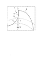
- FIG. 5 is a cross-sectional view taken along the line AA at a position 0.5D from the tip surface of the end mill. It is an enlarged view of the outer peripheral rake face of the outer peripheral blade in FIG.
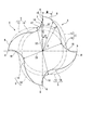
- FIG. 5 is a cross-sectional view taken along the line BB at a position 1.5D from the tip surface of the end mill.
- FIG. 3 is a cross-sectional view similar to FIG. 3 at a position 0.5D from the tip surface of the end mill according to the second embodiment. It is a cross-sectional view similar to FIG. 5 at a length position of 1.5D from the tip surface of the end mill.
- the end mill 1 is, for example, a 4-flute square end mill.
- the end mill 1 according to the embodiment includes a tool body 2 which is formed in a substantially columnar shape and is rotated about a central axis O, and a blade portion 3 formed at a tip portion thereof.
- the blade portion 3 side along the central axis O of the tool body 2 is referred to as the tip side
- the opposite side connected to the spindle is referred to as the proximal end side and the rear side.
- This end mill 1 is a small-diameter end mill formed in which the maximum outer diameter D of the bottom blade on the tip surface 4 of the blade portion 3 is, for example, in the range of 1 mm to 12 mm, preferably 1 to 6 mm, and is used for mechanical parts, dies, and the like. Is machined. Alternatively, the end mill 1 may have an outer diameter D of less than 1 mm. This end mill 1 is suitable for cutting difficult-to-cut materials such as stainless steel, titanium alloys, and heat-resistant alloys.
- a plurality of chip discharge grooves 5 twisted at a predetermined angle around the central axis O from the tip end side to the base end side are formed at predetermined intervals in the circumferential direction, for example, a four-row spiral shape. Is formed in.
- the outer peripheral blade 6 is formed at the intersecting ridge line portion between the wall surface facing the rotation direction and the outer peripheral surface connected to the rear in the rotation direction.
- the wall surface of the chip discharge groove 5 facing the rotation direction is the outer peripheral rake surface 7 of the outer peripheral blade 6, and the outer peripheral surface facing rearward in the rotation direction via the outer peripheral blade 6 is the outer peripheral relief surface 8.
- the four outer peripheral blades 6 are also arranged at predetermined intervals in the circumferential direction and are formed in a spiral shape.
- the outer peripheral relief surface 8 of the outer peripheral blade 6 has a convex curved surface shape along the rotation locus of the outer peripheral blade 6 and forms a positive clearance angle to secure the cutting edge strength of the outer peripheral blade 6.
- the outer peripheral flank surface 8 may be flat and have a positive flank angle.
- a pair of long blades 10 extending linearly from a pair of outer peripheral blades 6 facing the central axis O forming the center of rotation thereof, for example, toward the central axis O. Is formed rotationally symmetrically.
- a pair of short blades 11 are formed rotationally symmetrically on the front side of each long blade 10 in the rotational direction at a predetermined angle. The short blade 11 also extends continuously from the outer peripheral blade 6 on the outer peripheral surface toward the center side in the radial direction, for example, in a straight line.
- each short blade 11 is formed to have a length of, for example, about 1/2 of the radius (D / 2) of the tip surface 4 from the outer peripheral end connected to the outer peripheral blade 6. ing. Therefore, the short blade 11 does not reach the vicinity of the central axis O and is interrupted in the middle.
- the long blade 10 and the short blade 11 form a bottom blade.
- the long blade 10 is recessed toward the base end side of the short blade 11.
- the outer peripheral side region is first cut with the short blade 11 and is delayed.
- the central region (center axis O side) where the short blade 11 is not provided is cut by the long blade 10. Therefore, in the long blade 10, cutting is performed only at the cutting edge portion 10a in the central region that does not overlap with the short blade 11 that is rotationally cut.
- the cutting load of the long blade 10 and the short blade 11 can be set to be about the same, so that the long blade 10 can be cut. Vibration of the blade portion 10a and the short blade 11 can be suppressed.
- the bottom blade is unequally divided, it may be arranged evenly.
- the outer peripheral blades 6 connected to the long blade 10 and the short blade 11, respectively, may be arranged on equal leads or unequal leads. By arranging the outer peripheral blades 6 on the unequal leads, it is possible to suppress the occurrence of chatter vibration during the rotary cutting process of the end mill 1.
- the outer peripheral blades 6 may be arranged on equal leads or unequal leads.
- four gosh grooves 12 are formed at predetermined intervals on the front side in the rotation direction of the long blade 10 and the short blade 11 so as to be concavely cut toward the base end side.
- the gash groove 12 formed in front of the long blade 10 in the rotation direction is represented by reference numeral 12A
- the gash groove 12 formed in front of the short blade 11 in the rotation direction is represented by reference numeral 12B.
- the chip discharge groove 5 formed on the front side in the rotation direction of the outer peripheral blade 6 is formed by the first flute groove 13 and the second flute groove 14.
- the first flute groove 13 spirally extends the outer peripheral surface of the blade portion 3 from the tip surface 4 along the central axis O toward the base end side, and is cut off toward the outer peripheral side at the rear end.
- the second flute groove 14 forms a deeper flute groove by cutting the first flute groove 13 at the distal end side portion in the longitudinal direction of the first flute groove 13.
- Each second flute groove 14 is smoothly connected to each of the gash grooves 12A and 12B at the tip surface 4.
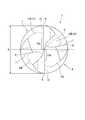
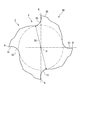
- FIG. 3 is an axis orthogonal cross-sectional view orthogonal to the central axis O at a position at a distance of 0.5D in the longitudinal direction from the tip surface 4 of the blade portion 3, and FIG. 5 is a center at a position at a distance of 1.5D from the tip surface. It is an axis orthogonal sectional view orthogonal to axis line O.
- the second flute groove 14 has a shorter length than the first flute groove 13, and is formed to have a length in the range of 0.5D to 1.5D from the tip surface 4 of the tool body 2 toward the base end side.
- the first flute groove 13 is formed to have a length longer than 1.5D from the tip surface 4.
- the end of the second flute groove 14 is formed at a position not reaching the length of 1.5D from the tip surface 4.
- the first flute groove 13 smoothly draws a concave curve in the circumferential direction from the outer peripheral blade 6 to form the first outer peripheral rake face 15, and is further curved in a convex curve to the front outer circumference. It is connected to the outer peripheral flank surface 8 of the blade 6.
- the second flute groove 14 formed by further cutting the first flute groove 13 is formed by partially cutting the first outer peripheral rake face 15 of the first flute groove 13 to form a concave curved surface in the circumferential direction and forming a second outer peripheral rake.
- a surface 17 is formed, and the surface 17 is further curved in a convex curve to be connected to the outer peripheral escape surface 8.
- the outer peripheral rake surface 7 of the portion of the second flute groove 14 on the tip end side of the outer peripheral blade 6 is formed by the first outer peripheral rake surface 15 and the second outer peripheral rake surface 17.
- An intersecting protrusion 16 is formed as a step at the intersection of the first outer peripheral rake face 15 and the second outer peripheral rake surface 17. As shown in FIG. 4, the intersecting protrusion 16 projects within 5 °, for example, 2.22 ° with respect to the virtual line L (radius) connecting the central axis O and the outer peripheral blade 6. Moreover, the intersecting protrusion 16 is formed at a position of 65% or more of the radius length D / 2 connecting the central axis O and the outer peripheral blade 6.
- the outer peripheral rake face 7 of the outer peripheral blade 6 is formed in two stages by the first outer peripheral rake surface 15 and the second outer peripheral rake surface 17, and the contact with chips is reduced by the intersecting protrusion 16 to reduce the traveling load and processing.
- the load is reduced.
- the protruding angle of the crossing protrusion 16 exceeds 5 °, it hinders the running of chips and prevents smooth flow.
- the position of the intersecting protrusion 16 is a length less than 65% of the radius D / 2 from the central axis O, the portion where the chips come into contact with the outer peripheral rake face 7 increases, and the effect of reducing the machining load is lost. ..
- the intersecting protrusion 16 extends from the front end side to the rear end side along the second flute groove 14, and ends at the end of the second flute groove 14.
- the first flute groove 13 and the second flute groove 14 are formed at the same depth in the direction along the central axis O except for the portion rounded up to the outer peripheral surface.
- the first core thickness S1 of the blade portion 3 in the tip side region where the second flute groove 14 is formed is formed in the range of 0.55D to 0.70D by the inscribed circle of the second flute groove 14. ..
- the chip discharge groove 5 in the tip side region where the second flute groove 14 is formed the tool rigidity is relatively small because the first core thickness S1 is small, but the groove depth is large and the chip discharge property is high. ..
- the second core thickness S2 of the blade portion 3 is set to 0 by the inscribed circle of the first flute groove 13. It is formed in the range of 60D to 0.80D.
- the second core thickness S2 of the first flute groove 13 is set to be 0.05D or more larger than the first core thickness S1 of the second flute groove 14, and the tool rigidity is high.
- the first core thickness S1 on the tip side on which the second flute groove 14 is formed is smaller than the second core thickness S2 on the base end side, and the tool rigidity is low. Therefore, in order to reinforce the tool rigidity, the following configuration is added to the outer peripheral relief surface 8 of the outer peripheral blade 6 in the region provided with the second flute groove 14.
- the outer peripheral flank 8 has a second flank connected to the rear side in the rotation direction of the outer peripheral blade 6, but the flank may be further rearward.
- the width M of the outer peripheral flank surface 8 of the outer peripheral blade 6 in the circumferential direction is set in the range of 0.05D to 0.25D.
- the rigidity of the portion of the outer peripheral flank surface 8 of the outer peripheral blade 6 is improved. If the width M of the outer peripheral flank 8 is smaller than 0.05D, the reinforcing effect of rigidity is small, and if it is larger than 0.25D, the width of the second flute groove 14 on the rear side in the rotation direction of the outer peripheral blade 6 becomes narrow, and chip evacuation is possible. Decreases.
- the radius D / 2 is 88 at a position 20 ° to the rear side in the rotation direction with respect to the radius of the virtual line L connecting the central axis O and the outer peripheral blade 6. It has a thickness of% to 97% and overhangs. At a position 30 ° to the rear side in the rotation direction with respect to the radius of the virtual line L, the thickness is 78% to 93% of the radius D / 2 and overhangs. Moreover, the inclination gradually changes from the position of 20 ° to the position of 30 °.
- the wall thicknesses at these 20 ° and 30 ° positions are formed in the second flute groove 14 that continues behind the outer peripheral escape surface 8 in the rotational direction, but can also be formed in the outer peripheral escape surface 8. If the thickness of the outer peripheral flank 8 is within this range, the tool rigidity can be improved without impairing the chip evacuation property. If the thickness of the outer peripheral relief surface 8 exceeds the above range, the width of the second flute groove 14 in the circumferential direction becomes small and the chip evacuation property decreases, and if it is smaller than the above range, the improvement of the tool rigidity cannot be achieved.
- the second core thickness S2 is larger than the first core thickness S1 and the tool rigidity is high. Therefore, the width M of the outer peripheral relief surface 8 and the wall thickness of the outer peripheral relief surface 8 at positions 20 ° and 30 ° rearward in the rotation direction of the outer peripheral blade 6 may be smaller than the region of the second flute groove 14.
- the end mill 1 has the above-described configuration.
- first drilling is performed to feed the work material in the O direction of the central axis, and then lateral feed is performed for shoulder cutting. Shall be performed.
- the cutting process is first performed with a pair of short blades 11 arranged on the outer peripheral side of the tip surface 4 of the blade portion 3. Do.
- the chips generated by the short blade 11 have a width and volume of about half that of cutting with the entire length of the long blade 10.
- the chips smoothly travel from the gash groove 12B through the second flute groove 14 of the chip discharge groove 5 and are discharged from the first flute groove 13. Further, the inner portion of the work material can be cut by the cutting edge portion 10a of the long blade 10 after the cutting by the short blade 11.
- the chips traveling in the chip discharge groove 5 travel in the first flute groove 13 and the second flute groove 14, the chips of the first outer peripheral rake surface 15 and the second outer peripheral rake surface 17, which are the outer peripheral rake surfaces 7, The vehicle travels in contact with the intersection 16. Therefore, the contact area of chips with respect to the first outer peripheral rake face 15 and the second outer peripheral rake surface 17 is small, and the resistance and machining load during running can be reduced. Moreover, since the second flute groove 14 is formed so as to overlap the first flute groove 13, the groove depth is large and the chip evacuation property is high.
- the second outer peripheral rake face 17 formed in the second flute groove 14 has a concave curved surface and a convex curved surface from an intermediate portion of the first outer peripheral rake surface 15 of the outer peripheral blade 6 toward the outer peripheral escape surface 8 of the outer peripheral blade 6 in the forward rotation direction. Since it is formed continuously, it is wide and chips can be smoothly discharged to the base end side.
- the first core thickness S1 on the tip side is the first behind it. It is smaller than the second core thickness S2 in the region where only the flute groove 13 is provided, and the tool rigidity is small.
- the outer peripheral relief surface 8 of each outer peripheral blade 6 is formed to have a wall thickness in the circumferential width M in the range of 0.05D to 0.25D.
- the outer peripheral flank surface 8 of the outer peripheral blade 6 is located at a position of 20 ° behind the rotation direction of the virtual line L connecting the central axis O and the outer peripheral blade 6, and has a radius D / 2 in the range of 88% to 97% and 30 °. At the position, it is formed overhanging to a wall thickness in the range of 78% to 93% of the radius D / 2. Therefore, the relatively small tool rigidity of the first core thickness S1 can be reinforced by the wall thickness of the outer peripheral flank surface 8, and both chip evacuation and tool rigidity can be improved. Further, since only the first flute groove 13 is formed on the base end side of the chip discharge groove 5, the second core thickness S2 is larger than the first core thickness S1 and the tool rigidity is high.
- the end mill 1 can be laterally fed to perform shoulder cutting of the machined surface of the work material.
- the chips cut by the outer peripheral blade 6 on the tip side travel on the first outer peripheral rake face 15 of the first flute groove 13 and the second outer peripheral rake face 17 of the second flute groove 14, but the intersecting protrusion 16
- the area of contact with the first outer peripheral rake face 15 and the second outer peripheral rake surface 17 is small. Therefore, the chips smoothly travel from the second flute groove 14 to the first flute groove 13 while suppressing the frictional resistance, and are discharged to the proximal end side.
- the second flute groove 14 is formed in the first flute groove 13 on the tip end side of the blade portion 3, the groove depth is deep and the chip evacuation property can be further improved.
- the second flute groove 14 is formed on the tip side of the blade portion 3 of the tool body 2 by overlapping with the first flute groove 13, the chip evacuation property on the tip side is improved. high. Further, the tool rigidity on the proximal end side is increased by forming the second flute groove 14 shorter than the first flute groove 13. Moreover, since the second flute groove 14 of the chip discharge groove 5 is formed from the first outer peripheral rake surface 15 side of the first flute groove 13 to the outer peripheral escape surface 8 in the circumferential direction, it is wide and has high chip discharge property.
- the intersecting protrusion 16 is provided at the intersection of the first outer peripheral rake face 15 and the second outer peripheral rake surface 17 formed in the first flute groove 13 and the second flute groove 14, the contact area of chips is increased. It runs less smoothly and is discharged.
- the second flute groove 14 is formed shorter than the first flute groove 13, and the first core thickness S1 of the region where the second flute groove 14 is formed is the region where only the first flute groove 13 on the base end side thereof is formed.
- the tool rigidity is small because it is smaller than the second core thickness S2.
- a predetermined width M is provided on the outer peripheral flank surface 8 of the outer peripheral blade 6, and the outer peripheral surface (outer peripheral flank surface) at positions 20 ° and 30 ° behind the virtual line L from the central axis O to the outer peripheral blade 6 in the rotation direction.
- the tool rigidity can be reinforced by projecting the wall thickness of the outer peripheral rake face 7) to 88 to 97% and 78% to 93% of the radius D / 2.
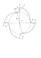
- FIG. 6 is a cross-sectional view of the blade portion 3 of the tool body 2 orthogonal to the central axis O at a distance of 0.5D from the tip surface 4
- FIG. 7 is a cross-sectional view orthogonal to the central axis O at a distance of 1.5D from the tip surface 4. It is a figure.
- a spiral outer peripheral blade 6 formed on the outer peripheral surface of the blade portion 3 is connected to the outer peripheral side ends of the long blade 10 and the short blade 11. ..
- a chip discharge groove 5 having an outer peripheral rake face 7 is formed on the front side in the rotation direction of the outer peripheral blade 6, and an outer peripheral relief surface 20 is formed on the rear side in the rotation direction of the outer peripheral blade 6.
- the outer peripheral rake face 7 has a large inclination angle in the region where the second flute groove 14 shown in FIG. 6 is provided.
- a step is formed between the outer peripheral relief surface 20 and the outer peripheral rake face 7 rearward in the rotational direction thereof.
- a second flute groove 14 is formed by cutting the bottom of the first flute groove 13 deeper at a position 0.5D from the tip surface 4 shown in FIG. 6 in the tip end side region of the blade portion 3.
- the second core thickness S2 is 0.05D or more larger than the first core thickness S1.
- the shape of the outer peripheral relief surface 20 is devised as in the first embodiment in order to reinforce the tool rigidity of the blade portion 3 on the tip side.
- the width M of the outer peripheral flank surface 20 of the outer peripheral blade 6 in the circumferential direction is set in the range of 0.05D to 0.25D.
- the rigidity of the portion of the outer peripheral flank surface 8 of the outer peripheral blade 6 is improved.
- the outer peripheral surface has a wall thickness of 88% to 97% of the radius length D / 2 in length from the central axis O.
- the outer peripheral flank 20 has a wall thickness of 78% to 93% of the radius length D / 2 in length from the central axis O. .. If the thickness of the outer peripheral flank surface 20 extends beyond the above range, the width of the second flute groove 14 in the circumferential direction becomes small and the chip evacuation property decreases, and if it is smaller than the above range, it cannot contribute to the improvement of tool rigidity. There are drawbacks. In the region of the first flute groove 13 in which the second flute groove 14 is not formed, the second core thickness S2 is larger than the first core thickness S1 and the tool rigidity is high.
- the width M of the outer peripheral relief surface 20 and the outer circumference The wall thickness of the outer peripheral flank surface 20 in the range of 20 ° to 30 ° on the rear side in the rotation direction of the blade 6 may be smaller than the region where the second flute groove 14 is provided.
- the two long blades 10 and the two short blades 11 are alternately arranged on the tip surface 4, and the outer peripheral blade 6 is a four-blade.
- the configuration is not limited to the bottom blade and the outer peripheral blade 6 having a single blade.
- the total of the bottom blade and the outer peripheral blade 6 may be arranged in 3 or 2 blades, or 5 or more blades.
- the bottom blade is not limited to the long blade 10 and the short blade 11, and a bottom blade having an appropriate length can be adopted.
- the rake face of the outer peripheral blade 6 is formed with an intersecting protrusion 16 as a step at the boundary between the first flute groove 13 and the second flute groove 14.
- the intersecting protrusion 16 is not always necessary, and the boundary between the first flute groove 13 and the second flute groove 14 in the circumferential direction may be formed in a smooth concave curve shape.
- the arrangement interval of the plurality of outer peripheral blades 6 arranged on the outer peripheral surface of the blade portion 3 can be appropriately set.
- the square end mill has been described as the end mill 1, but the present invention can be applied to various cutting tools such as a radius end mill, a ball end mill, and a drill instead.
- the present invention relates to a cutting tool including an end mill in which a bottom blade is formed on the tip surface of a tool body and an outer peripheral blade is formed on the outer peripheral surface.
- a plurality of outer peripheral blades formed in a spiral shape with a predetermined interval on the outer peripheral surface on the tip side of the tool body that can rotate around the central axis, and a plurality of outer peripheral blades formed on the front side in the rotation direction of the outer peripheral blades. It has a chip discharge groove and a plurality of bottom blades formed on the tip surface of the tool body and continuous with the outer peripheral blade.
- the chip discharge groove having the outer peripheral rake face of the outer peripheral blade has a length shorter than that of the first flute groove by cutting off the first flute groove extending from the tip surface to the rear end side and the tip side region of the first flute groove.
- the second flute groove is provided with a second flute groove whose rear end is connected to the first flute groove, and the second flute groove is formed in the circumferential direction from the outer rake face side of the first flute groove to the outer peripheral escape surface. It is characterized by being done.
- the core thickness on the tip side is made smaller than that on the rear end side by the second flute groove to deepen the chip discharge groove on the tip side and improve the chip discharge property.
- the tool rigidity on the tip side can be reinforced and the overall tool rigidity can be increased.
- the second flute groove on the tip side reaches from the outer peripheral rake face side of the outer peripheral blade to the outer peripheral relief surface of the outer peripheral blade in the circumferential direction, so that chips can be smoothly discharged while increasing the tool rigidity.
Landscapes
- Engineering & Computer Science (AREA)
- Mechanical Engineering (AREA)
- Milling Processes (AREA)
Applications Claiming Priority (2)
| Application Number | Priority Date | Filing Date | Title |
|---|---|---|---|
| JP2019097728A JP6902284B2 (ja) | 2019-05-24 | 2019-05-24 | 切削工具 |
| JP2019-097728 | 2019-05-24 |
Publications (1)
| Publication Number | Publication Date |
|---|---|
| WO2020240892A1 true WO2020240892A1 (ja) | 2020-12-03 |
Family
ID=73548461
Family Applications (1)
| Application Number | Title | Priority Date | Filing Date |
|---|---|---|---|
| PCT/JP2019/047381 Ceased WO2020240892A1 (ja) | 2019-05-24 | 2019-12-04 | 切削工具 |
Country Status (2)
| Country | Link |
|---|---|
| JP (1) | JP6902284B2 (enExample) |
| WO (1) | WO2020240892A1 (enExample) |
Cited By (1)
| Publication number | Priority date | Publication date | Assignee | Title |
|---|---|---|---|---|
| CN114535676A (zh) * | 2022-02-28 | 2022-05-27 | 广东鼎泰高科技术股份有限公司 | 一种可抑制毛刺的加工刀具 |
Citations (5)
| Publication number | Priority date | Publication date | Assignee | Title |
|---|---|---|---|---|
| JPH07204921A (ja) * | 1994-01-14 | 1995-08-08 | Hitachi Tool Eng Ltd | エンドミル |
| JP2000288826A (ja) * | 1999-04-05 | 2000-10-17 | Mitsubishi Materials Corp | エンドミル |
| JP2006212744A (ja) * | 2005-02-04 | 2006-08-17 | Nisshin Kogu Kk | エンドミル |
| JP2012091306A (ja) * | 2010-10-29 | 2012-05-17 | Hitachi Tool Engineering Ltd | 超硬合金製エンドミル |
| WO2017038763A1 (ja) * | 2015-08-28 | 2017-03-09 | 京セラ株式会社 | エンドミル及び切削加工物の製造方法 |
-
2019
- 2019-05-24 JP JP2019097728A patent/JP6902284B2/ja active Active
- 2019-12-04 WO PCT/JP2019/047381 patent/WO2020240892A1/ja not_active Ceased
Patent Citations (5)
| Publication number | Priority date | Publication date | Assignee | Title |
|---|---|---|---|---|
| JPH07204921A (ja) * | 1994-01-14 | 1995-08-08 | Hitachi Tool Eng Ltd | エンドミル |
| JP2000288826A (ja) * | 1999-04-05 | 2000-10-17 | Mitsubishi Materials Corp | エンドミル |
| JP2006212744A (ja) * | 2005-02-04 | 2006-08-17 | Nisshin Kogu Kk | エンドミル |
| JP2012091306A (ja) * | 2010-10-29 | 2012-05-17 | Hitachi Tool Engineering Ltd | 超硬合金製エンドミル |
| WO2017038763A1 (ja) * | 2015-08-28 | 2017-03-09 | 京セラ株式会社 | エンドミル及び切削加工物の製造方法 |
Cited By (2)
| Publication number | Priority date | Publication date | Assignee | Title |
|---|---|---|---|---|
| CN114535676A (zh) * | 2022-02-28 | 2022-05-27 | 广东鼎泰高科技术股份有限公司 | 一种可抑制毛刺的加工刀具 |
| CN114535676B (zh) * | 2022-02-28 | 2023-08-29 | 广东鼎泰高科技术股份有限公司 | 一种可抑制毛刺的加工刀具 |
Also Published As
| Publication number | Publication date |
|---|---|
| JP2020192611A (ja) | 2020-12-03 |
| JP6902284B2 (ja) | 2021-07-14 |
Similar Documents
| Publication | Publication Date | Title |
|---|---|---|
| JP6057038B1 (ja) | ドリル | |
| JP6473761B2 (ja) | エンドミルおよび切削加工物の製造方法 | |
| JP5845218B2 (ja) | ボールエンドミル | |
| JP5194680B2 (ja) | ラジアスエンドミル | |
| JP4125909B2 (ja) | スクエアエンドミル | |
| CN116060680A (zh) | 能够实现高斜向进刀角的旋转切削工具 | |
| JP2006000985A (ja) | 切削工具 | |
| JP6902284B2 (ja) | 切削工具 | |
| JP2004276142A (ja) | エンドミル | |
| JP6902285B2 (ja) | 切削工具 | |
| JP7138927B2 (ja) | ドリル | |
| JP2003275913A (ja) | ドリル | |
| WO2021260774A1 (ja) | 回転切削工具 | |
| JP2023140443A (ja) | エンドミル | |
| JP7706561B2 (ja) | 回転工具、及び切削加工物の製造方法 | |
| JP5439821B2 (ja) | ドリルおよび該ドリルの研削加工方法 | |
| WO2025187314A1 (ja) | ドリル | |
| WO2020202640A1 (ja) | 切削工具 | |
| JP2025135342A (ja) | ドリル | |
| JP2025068602A (ja) | リーマ | |
| JP2023140813A (ja) | エンドミル | |
| JP2023050214A (ja) | エンドミル | |
| JP2022129078A (ja) | 回転工具 | |
| JP2000288825A (ja) | エンドミル | |
| HK1168326A1 (en) | Ball end mill |
Legal Events
| Date | Code | Title | Description |
|---|---|---|---|
| 121 | Ep: the epo has been informed by wipo that ep was designated in this application |
Ref document number: 19931164 Country of ref document: EP Kind code of ref document: A1 |
|
| NENP | Non-entry into the national phase |
Ref country code: DE |
|
| 122 | Ep: pct application non-entry in european phase |
Ref document number: 19931164 Country of ref document: EP Kind code of ref document: A1 |