WO2020235134A1 - Dispositif d'analyse automatique - Google Patents
Dispositif d'analyse automatique Download PDFInfo
- Publication number
- WO2020235134A1 WO2020235134A1 PCT/JP2020/002083 JP2020002083W WO2020235134A1 WO 2020235134 A1 WO2020235134 A1 WO 2020235134A1 JP 2020002083 W JP2020002083 W JP 2020002083W WO 2020235134 A1 WO2020235134 A1 WO 2020235134A1
- Authority
- WO
- WIPO (PCT)
- Prior art keywords
- container
- reaction vessel
- dispensing
- automatic analyzer
- liquid level
- Prior art date
Links
Images


Classifications
-
- G—PHYSICS
- G01—MEASURING; TESTING
- G01N—INVESTIGATING OR ANALYSING MATERIALS BY DETERMINING THEIR CHEMICAL OR PHYSICAL PROPERTIES
- G01N35/00—Automatic analysis not limited to methods or materials provided for in any single one of groups G01N1/00 - G01N33/00; Handling materials therefor
- G01N35/02—Automatic analysis not limited to methods or materials provided for in any single one of groups G01N1/00 - G01N33/00; Handling materials therefor using a plurality of sample containers moved by a conveyor system past one or more treatment or analysis stations
- G01N35/04—Details of the conveyor system
-
- G—PHYSICS
- G01—MEASURING; TESTING
- G01N—INVESTIGATING OR ANALYSING MATERIALS BY DETERMINING THEIR CHEMICAL OR PHYSICAL PROPERTIES
- G01N35/00—Automatic analysis not limited to methods or materials provided for in any single one of groups G01N1/00 - G01N33/00; Handling materials therefor
- G01N35/10—Devices for transferring samples or any liquids to, in, or from, the analysis apparatus, e.g. suction devices, injection devices
- G01N35/1009—Characterised by arrangements for controlling the aspiration or dispense of liquids
-
- G—PHYSICS
- G01—MEASURING; TESTING
- G01N—INVESTIGATING OR ANALYSING MATERIALS BY DETERMINING THEIR CHEMICAL OR PHYSICAL PROPERTIES
- G01N35/00—Automatic analysis not limited to methods or materials provided for in any single one of groups G01N1/00 - G01N33/00; Handling materials therefor
- G01N35/00584—Control arrangements for automatic analysers
- G01N35/00594—Quality control, including calibration or testing of components of the analyser
- G01N35/00613—Quality control
- G01N35/00623—Quality control of instruments
-
- G—PHYSICS
- G01—MEASURING; TESTING
- G01N—INVESTIGATING OR ANALYSING MATERIALS BY DETERMINING THEIR CHEMICAL OR PHYSICAL PROPERTIES
- G01N35/00—Automatic analysis not limited to methods or materials provided for in any single one of groups G01N1/00 - G01N33/00; Handling materials therefor
- G01N35/00584—Control arrangements for automatic analysers
- G01N35/00594—Quality control, including calibration or testing of components of the analyser
- G01N35/00712—Automatic status testing, e.g. at start-up or periodic
-
- G—PHYSICS
- G01—MEASURING; TESTING
- G01N—INVESTIGATING OR ANALYSING MATERIALS BY DETERMINING THEIR CHEMICAL OR PHYSICAL PROPERTIES
- G01N35/00—Automatic analysis not limited to methods or materials provided for in any single one of groups G01N1/00 - G01N33/00; Handling materials therefor
- G01N35/00584—Control arrangements for automatic analysers
- G01N35/00722—Communications; Identification
-
- G—PHYSICS
- G01—MEASURING; TESTING
- G01N—INVESTIGATING OR ANALYSING MATERIALS BY DETERMINING THEIR CHEMICAL OR PHYSICAL PROPERTIES
- G01N35/00—Automatic analysis not limited to methods or materials provided for in any single one of groups G01N1/00 - G01N33/00; Handling materials therefor
- G01N35/10—Devices for transferring samples or any liquids to, in, or from, the analysis apparatus, e.g. suction devices, injection devices
- G01N35/1009—Characterised by arrangements for controlling the aspiration or dispense of liquids
- G01N35/1016—Control of the volume dispensed or introduced
-
- G—PHYSICS
- G01—MEASURING; TESTING
- G01N—INVESTIGATING OR ANALYSING MATERIALS BY DETERMINING THEIR CHEMICAL OR PHYSICAL PROPERTIES
- G01N35/00—Automatic analysis not limited to methods or materials provided for in any single one of groups G01N1/00 - G01N33/00; Handling materials therefor
- G01N35/00584—Control arrangements for automatic analysers
- G01N35/0092—Scheduling
- G01N2035/0094—Scheduling optimisation; experiment design
-
- G—PHYSICS
- G01—MEASURING; TESTING
- G01N—INVESTIGATING OR ANALYSING MATERIALS BY DETERMINING THEIR CHEMICAL OR PHYSICAL PROPERTIES
- G01N35/00—Automatic analysis not limited to methods or materials provided for in any single one of groups G01N1/00 - G01N33/00; Handling materials therefor
- G01N35/02—Automatic analysis not limited to methods or materials provided for in any single one of groups G01N1/00 - G01N33/00; Handling materials therefor using a plurality of sample containers moved by a conveyor system past one or more treatment or analysis stations
- G01N35/04—Details of the conveyor system
- G01N2035/046—General conveyor features
- G01N2035/0465—Loading or unloading the conveyor
-
- G—PHYSICS
- G01—MEASURING; TESTING
- G01N—INVESTIGATING OR ANALYSING MATERIALS BY DETERMINING THEIR CHEMICAL OR PHYSICAL PROPERTIES
- G01N35/00—Automatic analysis not limited to methods or materials provided for in any single one of groups G01N1/00 - G01N33/00; Handling materials therefor
- G01N35/10—Devices for transferring samples or any liquids to, in, or from, the analysis apparatus, e.g. suction devices, injection devices
- G01N35/1009—Characterised by arrangements for controlling the aspiration or dispense of liquids
- G01N2035/1025—Fluid level sensing
-
- G—PHYSICS
- G01—MEASURING; TESTING
- G01N—INVESTIGATING OR ANALYSING MATERIALS BY DETERMINING THEIR CHEMICAL OR PHYSICAL PROPERTIES
- G01N27/00—Investigating or analysing materials by the use of electric, electrochemical, or magnetic means
- G01N27/02—Investigating or analysing materials by the use of electric, electrochemical, or magnetic means by investigating impedance
- G01N27/22—Investigating or analysing materials by the use of electric, electrochemical, or magnetic means by investigating impedance by investigating capacitance
Definitions
- the present invention relates to the technique of an automatic analyzer.
- the automatic analyzer for clinical examination is indispensable for the current diagnosis because the analysis result is highly reproducible and the processing speed is fast.
- This automatic analyzer analyzes a reaction solution prepared by dispensing a sample and a reagent into a reaction vessel. Analysis methods in this automatic analyzer include colorimetric analysis and immunoassay.
- Colorimetric analysis is an analysis method that uses a reagent that changes the color of the reaction solution by reacting with the component to be analyzed in the sample.
- Immunoassay is an analysis method for counting labeled substances using a reagent in which a labeled substance is added to a substance that directly or indirectly specifically binds to the component to be analyzed in a sample.
- the automatic analyzer of the prior art example uses a reaction vessel in which a sample or the like is dispensed, and then controls to discard the vessel.
- the reaction vessel is a type of container that is disposable each time.
- the automatic analyzer transports the reaction vessel on the reaction vessel holding mechanism to a disposal box or the like for disposal.
- Patent Document 1 describes a dispensing abnormality detecting means (for example, FIG. 3 etc.) in the automatic analyzer.
- Patent Document 2 describes means for detecting the liquid level in a container (for example, FIG. 5 and the like) in an immunoagglutination measuring device.
- the automatic analyzer of the prior art example controls to discard all the reaction vessels on the reaction vessel holding mechanism when the apparatus operation is restarted after the apparatus operation is stopped due to, for example, an apparatus abnormality detection. This is because ensuring safety is the first priority, and to avoid using the used reaction vessel in the next analysis.
- Multiple reaction vessels at multiple positions in the reaction vessel holding mechanism may contain a mixture of used reaction vessels containing the reaction solution and unused reaction vessels containing no reaction solution. There is. In the case of the above control, the unused reaction vessel in the reaction vessel holding mechanism is discarded and wasted even though it may be usable.
- the automatic analyzer of the prior art example has room for improvement in terms of efficiency of container disposal and utilization.
- An object of the present invention is to provide a technique capable of efficiently controlling the disposal and utilization of a container with respect to an automatic analyzer.
- the automatic analyzer includes a control device for controlling sample analysis, a container holding mechanism capable of installing a plurality of containers at a plurality of positions, and the sample and the reagent in the container.
- the control device includes a transport mechanism for transporting the container at a position when it is disposed of in a disposal box, the dispensing mechanism includes a liquid level detecting mechanism for detecting the liquid level of the liquid in the container, and the control device includes a liquid level detecting mechanism.
- a state including the presence or absence of the container in which the reaction liquid is contained can be determined.
- the position is controlled so as to execute the disposal operation using the transport mechanism, and the position when it is determined that the container is not present is determined.
- the disposal operation using the transport mechanism is controlled so as not to be executed.
- the figure which shows the structure of the automatic analyzer The figure which shows the functional block composition of the automatic analyzer of Embodiment 1.
- FIG. The figure which shows the reaction container installation position of the incubator in Embodiment 1.
- FIG. The figure which shows the example of the whole processing flow in Embodiment 1.
- FIG. The figure which shows the control outline in Embodiment 1.
- FIG. The figure which shows the liquid level detection in Embodiment 1.
- FIG. which shows the processing flow example of the container state determination in Embodiment 1.
- FIG. The figure which shows the abnormality descent detection in Embodiment 2.
- the automatic analyzer of the prior art example has two types of reaction vessels, one is a disposable type reaction vessel that is discarded after use, and the other is a type reaction vessel that is washed and reused many times. There are types. Suitable containers are used depending on the analysis. In the case of a disposable type reaction vessel, the following installation and disposal controls are performed. The automatic analyzer controls the disposal of the container at specified timings such as before analysis, during analysis, and when the device operation is restarted. “Before analysis” is a time before performing an analysis preparation step (step S3 in FIG. 4 described later) including dispensing and the like. The term “during analysis” means during or after an analysis step (step S4 in FIG. 4 described later) including optical measurement and the like. The time when the device operation is restarted is the time when the device operation is restarted after the device operation is stopped due to the device abnormality detection.
- the automatic analyzer grips the reaction vessel from the reaction vessel tray in which the disposable type reaction vessel is stored by the transport mechanism, and transports the reaction vessel to a predetermined position on the incubator which is the reaction vessel holding mechanism. And install.
- the automatic analyzer prepares a mixed solution by dispensing a sample and a reagent into a reaction vessel at a predetermined position on an incubator by a dispensing mechanism.
- the automatic analyzer incubates, in other words, prepares the reaction solution by holding the reaction vessel containing the mixed solution in an incubator for a predetermined time.
- the automatic analyzer moves the target reaction vessel to the detection mechanism by the transfer mechanism, and performs optical measurement on the reaction solution in the reaction vessel. After that, the automatic analyzer transports the reaction vessel used in the analysis to the disposal box by the transport mechanism and discards it.
- the automatic analyzer of the prior art example performs a disposal operation for all reaction vessels at all positions on the incubator, which is a reaction vessel holding mechanism, at a specified timing such as before analysis or when the operation is restarted. This is because, as mentioned above, ensuring safety is the first priority, and to avoid using the used reaction vessel in the next analysis.
- the automatic analyzer stops the operation of the device due to the detection of some abnormality, and then resumes the operation of the device after troubleshooting or the like. When the operation of the apparatus is stopped, there is a possibility that a used reaction vessel containing the reaction solution and an unused reaction vessel containing no reaction solution are mixed on the incubator.
- the automatic analyzer of the prior art example performs an operation of discarding all the reaction vessels on the incubator at a predetermined timing without making a special determination, for example, a determination for each position or a determination of the container usage status. In this case, even if there is an unused reaction vessel on the incubator, the reaction vessel is discarded and isted.
- disposal operation, installation operation, etc. are required for each position at multiple positions on the incubator (sometimes referred to as installation position). Therefore, depending on the number of installation positions in the incubator, the number of reaction vessels that can be installed, the number of transfer mechanisms for transporting the reaction vessels, etc., the disposal operation, installation operation, etc. may take a long time for analysis. There is also the issue of delaying the start.
- the disposal operation is an operation in which one transport mechanism accesses each reaction vessel at one installation position, grips the reaction vessel, transports the reaction vessel, and disposes of the reaction vessel.
- the installation operation is an operation in which one transport mechanism accesses the reaction vessel tray, grips one reaction vessel, and transports and installs one reaction vessel to one installation position on the incubator.
- the automatic analyzer of the prior art example detects the presence or absence of a reaction vessel by using a dedicated sensor (in other words, a container presence / absence sensor).
- a dedicated sensor in other words, a container presence / absence sensor.
- at least one dedicated sensor is provided at the installation position of the reaction vessel on the incubator. This sensor detects whether or not there is a reaction vessel at the installation position by using, for example, light reflection. Using this sensor, the presence or absence of a reaction vessel on the incubator can be detected. Then, it is conceivable to control the disposal operation or the like according to the presence or absence of the reaction vessel by using the detection result of this sensor.
- this method is expensive because it requires a dedicated sensor. In particular, when the sensor is provided at each of a plurality of positions on the incubator, the cost is higher.
- this method can detect the presence or absence of the reaction vessel at the target position, it does not detect or judge the usage status such as the presence or absence of the reaction solution in the reaction vessel. Therefore, even if this method is used, all the reaction vessels on the incubator will be uniformly discarded regardless of the usage status of the reaction vessel. Unused reaction vessels on the incubator are discarded even though they may be used for the next analysis as they are.
- the automatic analyzer of the first embodiment will be described with reference to FIGS. 1 to 7.
- the automatic analyzer of the first embodiment has a function of checking and determining the state of the reaction vessel on the incubator, which is a reaction vessel holding mechanism, at a predetermined timing, and controlling the disposal operation or the like according to the result of the determination.
- the automatic analyzer of the first embodiment determines the state of the reaction vessel at each position of the incubator by using a dispensing mechanism without using a dedicated sensor.
- the automatic analyzer of the first embodiment determines the state of the reaction vessel by using the liquid level detection mechanism provided in the dispensing mechanism.
- the control device determines, as at least, a state in which the reaction vessel containing the reaction solution is not installed and a state in which the reaction vessel containing the reaction solution is installed. Then, the automatic analyzer of the first embodiment determines and controls the disposal operation or the like for each position according to the state of the result of the determination.
- FIG. 1 shows the configuration of the upper surface of the automatic analyzer according to the first embodiment.
- the automatic analyzer of the first embodiment includes a control device 100, an incubator 1, a common disk 3, a dispensing mechanism 8, 9, a pump 10, 11, a washing tank 12, 13, a reagent stirring mechanism 14, a spectrophotometer 15, and detection. It includes a mechanism 16, a transport mechanism 17, a dispensing chip tray 19, a reaction vessel tray 20, a waste box 21, a water supply tank 24, a waste liquid tank 25, a first liquid container 26, a cleaning liquid container 27, and the like.
- X direction, Y direction, and Z direction are shown.
- the X direction and the Y direction are two orthogonal directions forming a horizontal plane, the X direction is the lateral direction of the device, and the Y direction is the depth direction of the device.
- the Z direction is the vertical direction and the device height direction.
- the control device 100 is a device including a control unit and a storage unit, and will be described later with reference to FIG.
- the incubator 1 is a disk-shaped or columnar reaction vessel holding mechanism, and includes a rotating mechanism. As shown in FIG. 3 described later, a plurality of reaction vessels 2 can be installed and held at a plurality of positions on the circumference of the incubator 1.
- the incubator 1 has a temperature control mechanism for maintaining the held reaction vessel 2 at a predetermined time and a predetermined temperature, thereby promoting a chemical reaction of the reaction solution.
- the reaction vessel 2 is a vessel for accommodating a reaction solution based on a mixed solution of a sample and a reagent. As the reaction vessel 2, two types, the reuse type and the disposable type described above, can be applied. In the first embodiment, the reaction vessel 2 used is a disposable type reaction vessel as a common vessel for all analyzes.
- the incubator 1 is controlled by the control device 100 and the drive mechanism (FIG. 2 described later) so as to rotate a predetermined distance in one cycle.
- the predetermined distance is a distance corresponding to a predetermined number of reaction vessels 2.
- Incubator 1 repeats rotation and rest in a plurality of cycles. As a result, each reaction vessel 2 on the incubator 1 moves in sequence, and a specified process such as dispensing is performed at each specified position.
- the common disk 3 is a disk-shaped container holding mechanism for commonly installing and holding a sample container 5 (for example, a sample cup) and a reagent container 4 (for example, a reagent bottle), and includes a rotation mechanism.
- the common disk 3 is a mechanism in which the sample container holding mechanism and the reagent container holding mechanism are unified into one.
- the common disc 3 has a cold storage and a cover.
- a plurality of sample containers 5 and a plurality of reagent containers 4 can be installed and held at a plurality of positions on the circumference.
- the common disk 3 has a structure in which the sample container 5 is installed on the outer peripheral side and the reagent container 4 is installed on the inner peripheral side, but the present invention is not limited to this.
- the common disk 3 may have a structure in which the reagent container 4 is installed on the outer peripheral side and the sample container 5 is installed on the inner peripheral side.
- the common disk 3 may have a structure in which each container can be installed without being divided into an inner circumference and an outer circumference.
- the sample container holding mechanism and the reagent container holding mechanism may be provided independently in a structure such as a disk or a rack, respectively.
- the reagent suction position 6 is a predetermined position for sucking the reagent from the reagent container 4 on the circumference of the common disk 3 and in an orbit where the nozzles of the dispensing mechanisms 8 and 9 can access during dispensing. is there.
- the sample suction position 7 is a predetermined position for sucking a sample from the sample container 5 on the circumference of the common disk 3 and on an orbit where the nozzles of the dispensing mechanisms 8 and 9 can access during dispensing. is there.
- Dispensing mechanisms 8 and 9 and cleaning tanks 12 and 13 are arranged between the incubator 1 and the common disk 3.
- the dispensing mechanism 8 is the first dispensing mechanism.
- the dispensing mechanism 9 is a second dispensing mechanism.
- the dispensing mechanisms 8 and 9 each include a rotating shaft, an arm, a nozzle, and the like.
- the dispensing mechanisms 8 and 9, respectively, can rotate the arm and the nozzle around the rotation axis as shown by the arc of the broken line.
- a nozzle is connected vertically below the tip of each arm. Each nozzle can move up and down in the vertical direction.
- a pump 10 is connected to the nozzle of the dispensing mechanism 8.
- a pump 11 is connected to the nozzle of the dispensing mechanism 9.
- two dispensing mechanisms a dispensing mechanism 8 and a dispensing mechanism 9, are provided, but the present invention is not limited to this.
- the dispensing mechanisms 8 and 9 are arranged so that the trajectories of the nozzles and the mechanisms do not physically interfere with each other.
- the two dispensing mechanisms 8 and 9 are used properly for inspections of different analytical processes.
- the dispensing mechanism 8 is used for biochemical testing and the dispensing mechanism 9 is used for immunological testing.
- the dispensing mechanism 8 dispenses samples and reagents for biochemical analysis.
- the dispensing mechanism 9 dispenses samples and reagents for immunoassay.
- a disposable type dispensing tip 18 is used for dispensing.
- a dispensing tip 18 is attached to the nozzle of the dispensing mechanism 9.
- the automated analyzer of Embodiment 1 uses a disposable reaction vessel 2 for both biochemical and immunological tests. In any of the tests, the automatic analyzer of the first embodiment accesses the sample to be measured and dispenses the sample by the corresponding dispensing mechanism.
- a configuration may include one dispensing mechanism or three or more dispensing mechanisms.
- the dispensing mechanism 9 On the orbit of the nozzle of the dispensing mechanism 8, the sample suction position 7 and the reagent suction position 6 on the common disk 3 and the first dispensing position and the second dispensing position on the incubator 1 (FIG. 3 described later). , There is a cleaning tank 12. On the orbit of the nozzle of the dispensing mechanism 9, the sample suction position 7 and the reagent suction position 6 on the common disk 3 and the first dispensing position and the second dispensing position on the incubator 1 (FIG. 3 described later). , There is a cleaning tank 13. Further, in order to use the dispensing chip 18, the dispensing mechanism 9 has a dispensing chip mounting position 22 and a dispensing chip disposal position 23 on the trajectory of the nozzle.
- the nozzle of the dispensing mechanism 8 moves to the sample suction position 7 while drawing an arc around the rotation axis, descends into the sample container 5 at that position, and samples from the sample container 5. Ascend by sucking. Then, the nozzle of the dispensing mechanism 8 moves to the first dispensing position or the second dispensing position on the incubator 1, descends into the reaction vessel 2 at that position, discharges the sample, and rises.
- the dispensing mechanisms 8 and 9 suck the sample or reagent through the nozzle, access the inside of the reaction vessel 2, and discharge the sample or reagent. At that time, the dispensing mechanisms 8 and 9 agitate the sample, the reagent, or a mixture thereof in the reaction vessel 2 by repeating the suction and discharge operations of the nozzle to promote the mixing.
- the pump 10 is a pump for the first dispensing mechanism, and is used for suction and discharging by the dispensing mechanism 8.
- the pump 11 is a pump for the second dispensing mechanism, and is used for suction and discharging by the dispensing mechanism 9.
- the cleaning tank 12 is a first dispensing nozzle cleaning tank, and cleans the nozzles of the dispensing mechanism 8.
- the cleaning tank 13 is a second dispensing nozzle cleaning tank, and cleans the nozzles of the dispensing mechanism 9.
- the reagent stirring mechanism 14 grips the reagent bottle 4 and stirs the reagent.
- the spectrophotometer 15 is a photometer for biochemical examination, and is arranged at a predetermined position around the incubator 1.
- the spectrophotometer 15 includes a light source and a detector.
- the spectrophotometer 15 performs optical measurement on the reaction solution of the reaction vessel 2 at a predetermined position.
- the spectrophotometer 15 measures the absorbance of the reaction solution by irradiating the reaction solution of the reaction vessel 2 with light from a light source and detecting the transmitted light by spectroscopically detecting the reaction solution.
- the detection mechanism 16 is a detection mechanism for immunoassay, and performs optical measurement of the reaction solution at the time of immunoanalysis.
- the automatic analyzer moves the reaction vessel 2 containing the reaction solution reacted on the incubator 1 for a predetermined time to the detection mechanism 16 by the transport mechanism 17.
- the detection mechanism 16 performs optical measurement on the reaction solution of the reaction vessel 2.
- Immunotests include electrochemical luminescence and chemiluminescence-based methods for detecting labeling substances. A second liquid or labeling substance suitable for each method, the structure and physical properties of the detection region are selected.
- the detection mechanism 16 measures the amount of luminescence derived from the luminescence reaction of the labeling substance using a photomultiplier tube as a detector.
- the transport mechanism 17 is arranged between the incubator 1, the detection mechanism 16, the reaction vessel tray 20, the disposal box 21, and the like.
- the transport mechanism 17 is a mechanism for transporting the reaction vessel 2, the dispensing chip 18, and the like between the mechanisms.
- the transport mechanism 17 is provided with a gripper at its tip that can grip the reaction vessel 2 and the dispensing tip 18.
- the transport mechanism 17 is movable in the X and Y directions along a rail or the like, is rotatable around a rotation axis, and has a tip that is vertically movable in the Z direction.
- the transport mechanism 17 can grip and release the reaction vessel 2 and the dispensing tip 18 by the operation of the tip.
- the reaction vessel tray 20 holds a plurality of unused reaction vessels 2.
- the dispensing tip 18 is a tip attached to the tip of the nozzle of the dispensing mechanism 9 at the time of dispensing in the case of immunoassay, and is used as a single disposable item.
- the dispensing chip tray 19 holds a plurality of unused dispensing chips 18. The reaction vessel tray 20 and the dispensing chip tray 19 can be appropriately replenished with the reaction vessel 2 and the like by the user.
- the disposal box 21 is a disposal box for the reaction vessel 2 and the dispensing chip 18 to be discarded.
- the disposal box 21 houses the reaction vessel 2 and the dispensing chip 18 that have been transported and discarded by the transport mechanism 17.
- the disposal box 21 can be taken out by the user through a drawer or the like.
- the dispensing tip mounting position 22 is a predetermined position for mounting the dispensing chip 18 on the nozzle of the dispensing mechanism 9.
- the dispensing chip disposal position 23 is a predetermined position for discarding the dispensing chip 18 from the nozzle of the dispensing mechanism 9.
- the disposal position of the reaction vessel 2 is a position vertically above the disposal box 21.
- the water supply tank 24 is a tank for accumulating system water.
- the waste liquid tank 25 is a tank for accumulating waste liquid.
- the first liquid container 26 is a container for holding the first liquid involved in the analysis.
- the cleaning liquid container 27 is a container for holding the cleaning liquid.
- the reaction vessel 2 for which analysis (for example, measurement of absorbance) has been completed is moved to the disposal box 21 by the transport mechanism 17 and discarded.
- the transport mechanism 17 accesses the target position on the incubator 1, grips the reaction vessel 2 at that position, transports the reaction vessel 2 onto the waste box 21, and releases the reaction vessel 2.
- the reaction vessel 2 is dropped and accommodated in the disposal box 21.
- the reaction vessel 2 for which the optical measurement by the detection mechanism 16 has been completed is similarly conveyed to the disposal box 21 by the conveying mechanism 17 and discarded.
- the automatic analyzer of the first embodiment realizes the stirring function by using the dispensing mechanisms 8 and 9, an independent stirring mechanism may be provided.
- the transport mechanism 17 is a mechanism capable of realizing a plurality of types of operations including an operation of installing the reaction vessel 2 and an operation of discarding the reaction vessel 2, but the transfer mechanism 17 is not limited to this and can perform various operations. It may be realized by another mechanism.
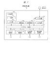
- FIG. 2 shows a functional block configuration particularly related to the control device 100 in the automatic analyzer of the first embodiment.
- the automatic analyzer of the first embodiment includes a control device 100, a storage device 103, an input device 104, an output device 105, a power supply device 106, an interface circuit 110, a common disk drive unit 113, an incubator drive unit 111, and a dispensing mechanism drive unit. It includes 115, a transport mechanism drive unit 117, and the like. Each mechanism is connected to the control device 100 through an interface circuit 110 including a bus, a cable, and the like.
- the control device 100 includes at least one of the IC board 101 and the computer 102.
- the control device 100 includes a processor and a memory, and controls the entire automatic analyzer. By controlling each drive unit, the control device 100 controls the rotation of the incubator 1, the rotation of the common disk 3, the dispensing operation of the dispensing mechanisms 8 and 9, the transport operation of the transport mechanism 17, and the like.
- the storage device 103 stores control data, information, and the like.
- the input device 104 includes an operation panel and the like.
- the output device 105 includes a display device, a printing device, a light emitting device such as an LED, and an audio output device such as a speaker.
- the power supply device 106 supplies electric power to each unit.
- the common disk drive unit 113 is a mechanism including a motor and the like, and drives the rotation and the like of the common disk 3 in accordance with a command from the control device 100.
- the incubator drive unit 111 is a mechanism including a motor and the like, and drives the rotation and the like of the incubator 1 in accordance with a command from the control device 100.
- the dispensing mechanism driving unit 115 is a mechanism including a motor and the like, and drives the operations of the dispensing mechanisms 8 and 9 by driving the nozzles, the phons 10, 11 and the like in accordance with a command from the control device 100.
- the transport mechanism drive unit 117 is a mechanism including a motor and the like, and drives the operation of the transport mechanism 17 in accordance with a command from the control device 100.
- the control device 100 is also connected to the spectrophotometer 15 and the detection mechanism 16, and inputs signals from them to perform analysis processing.
- the control device 100 receives a user's input operation through the input device 104.
- the control device 100 outputs the analysis processing result from the output device 105 to the user.
- the control device 100 detects an abnormality in the device, the control device 100 stops the operation of the device and provides the user with a guide such as a graphical user interface (GUI) for troubleshooting through the output device 105.
- GUI graphical user interface
- the container to be controlled uniquely in the first embodiment is the reaction container 2.
- the reaction container 2 There are various possible states of the reaction vessel 2, and for example, there are the following states. (1) None is housed. (2) A state in which only the sample is contained. (3) A state in which only reagents are stored. (4) A state in which a mixed solution of a sample and a reagent or a reaction solution is contained. (5) A state in which the cleaning liquid is contained. (6) A state in which blank water is contained.
- the state of the "unused reaction vessel” in the first embodiment corresponds to the state of (1) above.
- the state of the "used reaction vessel” corresponds to the states (2) to (6) above.
- the automatic analyzer of the first embodiment includes a mechanism that enables both biochemical analysis and immunoanalysis with one unit. Specifically, as shown in FIG. 1, this automatic analyzer is provided with two dispensing mechanisms 8 and 9 as dispensing mechanisms, and the two dispensing mechanisms 8 and 9 are used for biochemical analysis and immunoanalysis. Use properly.
- This automatic analyzer is provided with various mechanisms necessary for various types of analysis, and is implemented as a common mechanism (for example, a common disk 3) for parts that can be shared in various types of analysis.
- a reaction vessel 2 used for biochemical analysis and a reaction vessel 2 used for immunoassay can be mixed on the incubator 1, and both analyzes can be performed in parallel.
- the automatic analyzer of the other embodiment may have only an immunoassay function.
- the dispensing mechanisms 8 and 9 each include a liquid level detection mechanism and an abnormal drop detection mechanism, which will be described later.
- the liquid level detection mechanism is a mechanism including a liquid level detector that detects the liquid level in the container in order to determine a suitable position for the nozzle to descend and stand still when dispensing the sample or reagent.
- the abnormal descent detection mechanism is a mechanism including a detector that detects abnormal descent (corresponding contact, etc.) of the dispensing mechanism including the nozzle at the time of dispensing.
- the automatic analyzer of the prior art example is provided with a detection mechanism including such a detector for the purpose of improving the efficiency and accuracy of dispensing, preventing damage to the container and the dispensing mechanism, and the like.
- FIG. 3 shows a schematic configuration of the upper surface of the incubator 1 and shows the installation position of the reaction vessel 2.
- 64 positions indicated by numbers 1 to 64 are defined as a plurality of installation positions on the circumference of the upper surface of the incubator 1. Since the incubator 1 is rotationally driven, the positions on the circumference of the incubator 1 (corresponding installation holes and reaction vessel 2) rotate and move.
- the positions accessible by the dispensing mechanisms 8 and 9 and the transport mechanism 17 are particularly the positions P1, P4, P34, P36, It has P47.
- Position P1 is a specified position (referred to as the first dispensing position) for dispensing and stirring the first reagent and sample for biochemical examination.
- Position P4 is a defined position (referred to as the second dispensing position) for dispensing and stirring the second reagent and sample for biochemical testing.
- Position P34 is a defined position for the installation of the reaction vessel 2 for biochemical inspection.
- the position P36 is a take-out position of the reaction vessel 2 for the biochemical test, an installation position of the reaction vessel 2 for the immunological test, and a specified position for the take-out position.
- Position P47 is the first dispensing position for dispensing and stirring for immunoassay.
- Position P55 is the second dispensing position for dispensing and stirring for immunoassay.
- the configuration of FIG. 3 is an example, and the optimum values for the number and positions of a plurality of positions in the incubator 1 are the difference in reaction time of different reaction processes, the orbital radii of the dispensing mechanisms 8 and 9, and the dispensing mechanism 8. , 9 and the arrangement of the transport mechanism 17, etc., depending on various parameters.
- the automatic analyzer can access the predetermined position of the incubator 1.
- the nozzle of the dispensing mechanism 8 can access positions P1 and P4.
- the nozzle of the dispensing mechanism 9 can access positions P47 and P55.
- the transport mechanism 17 can access the position P34 and the position P36.
- the automatic analyzer executes a container condition check (step S1 or step S9 in FIG. 4) described later at a predetermined position in the incubator 1. For example, when checking the container state using the dispensing mechanism 8, at least one of the positions P1 and P4 may be used. In this example, when checking the container condition, the dispensing mechanism 8 uses the position P1 and the dispensing mechanism 9 uses the position P47.
- the control device 100 controls the rotation drive of the incubator 1 to perform all positions of the incubator 1 (corresponding installation holes and reaction vessels) with respect to predetermined positions (for example, positions P1 and P47) for checking the container state.
- predetermined positions for example, positions P1 and P47
- the automatic analyzer of the first embodiment attaches importance to the certainty for the next analysis, and applies the container state check to all the positions (positions P1 to P64) of the incubator 1.
- the container condition check may be applied to a part of the position of the incubator 1.
- the control device 100 may check the container state only at a part of the positions based on the management information. In this case, the time required for checking the container condition can be shortened.
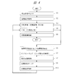
- FIG. 4 shows an example of a processing flow related to the entire analysis in the automatic analyzer of the first embodiment.
- FIG. 4 has steps S1 to S10, which will be described below in the order of steps.
- the control device 100 executes a container state check, for example, after starting the device, and grasps the state of each position on the incubator 1.
- the control device 100 executes the container disposal control according to the result of the check in step S1.
- the control device 100 executes a prescribed analysis preparation step.
- This analysis preparation step includes a step of installing a reaction vessel 2 on the incubator 1 and dispensing a sample and a reagent into the reaction vessel 2 to prepare a reaction solution.
- step S4 the control device 100 performs an analysis step such as a designated biochemical analysis or immunoassay using the reaction solution of the reaction vessel 2 prepared for analysis.
- This analytical step includes optical measurement and analytical processing of the reaction solution.
- the control device 100 stores the analysis result in the storage device 103 and outputs the analysis result to the user through the output device 105.
- step S5 the control device 100 performs a disposal operation on the reaction vessel 2 and the dispensing chip 18 used in the analysis. Steps S3 to S5 are similarly repeated for each reaction vessel 2 to be analyzed, and when all the analyzes are completed, this flow ends.
- step S6 the control device 100 shifts to step S6 in response to the device abnormality detection, and temporarily stops the device operation.
- step S7 the control device 100 performs troubleshooting and the like for dealing with the abnormality.
- the control device 100 provides the user with a GUI screen or the like for troubleshooting or guiding maintenance work. The user performs maintenance work for dealing with an abnormality through a GUI screen or the like.
- step S8 the control device 100 confirms that the automatic analyzer has become a normal state, and controls to restart the device operation.
- step S9 the control device 100 checks the container state in the same manner as in step S1 as the operation resumes.
- step S10 the control device 100 controls the disposal of the reaction vessel 2 according to the result of the check in step S9, and then returns to the state before the stop such as step S3 or step S4.
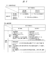
- FIG. 5 shows a table summarizing the control outline in the first embodiment.
- the table (A) shows the outline of the container state determination
- the table (B) shows the outline of the disposal control and the like corresponding to (A).
- the second row shows the presence / absence of liquid level detection using the liquid level detection mechanisms of the dispensing mechanisms 8 and 9.
- No liquid level detection corresponds to a state where there is no liquid such as a reaction liquid.
- the presence of liquid level detection corresponds to the state where there is a liquid such as a reaction liquid.
- the item for each row indicates the value of the state determination result according to the liquid level detection result. There are two types of values for this value: (1) “without reaction vessel” and (3) “with used reaction vessel”.
- the control device 100 detects the presence or absence of the liquid level when the nozzle is lowered by the liquid level detection mechanisms of the dispensing mechanisms 8 and 9, and based on the detection result, the state of the reaction vessel 2 at the target position is set to (1) “Reaction”.
- the state of "without container” and the state of (3) "with used reaction container” are discriminated.
- the control device 100 determines that (1) “without reaction vessel” when there is no liquid level detection, and (3) "with used reaction vessel” when there is liquid level detection. Determined to be in a state.
- (1) The state of "without reaction vessel” is a state in which the reaction vessel 2 is not installed at the target position.
- the state of "with used reaction vessel” is a state in which the reaction vessel 2 containing the reaction solution is installed.
- the items for each row indicate the control contents of the disposal operation and the transport operation according to the judgment result value of (A).
- the control device 100 determines that (1) in the case of the "no reaction vessel" state, the disposal operation at the target position (the corresponding position determined to be "no reaction vessel") is unnecessary for the disposal control.
- the disposal operation is an operation in which the transport mechanism 17 accesses the target position on the incubator 1, grips the reaction vessel 2, transports it to the waste box 21, and disposes of it. Further, regarding the transfer control, the control device 100 acquires the unused reaction container 2 from the reaction container tray 20 at the time of the next analysis, and transfers the unused reaction container 2 to the target position on the incubator 1 for installation. Control.
- steps S3 and S4 correspond to steps S1 and S2 or steps S9 and S10.
- the control device 100 determines that a disposal operation at the target position (corresponding position determined to have “used reaction vessel") is required for disposal control. ..
- the control device 100 moves the target position on the incubator 1 to a position accessible by the transport mechanism 17 (position P34 or position P36 in FIG. 3). Then, the control device 100 controls so that the transport mechanism 17 transports the used reaction vessel 2 at the target position to the waste box 21 and discards it. Further, at the time of the next analysis, the control device 100 controls the transporter mechanism 17 to acquire the unused reaction vessel 2 from the reaction vessel tray 20 and install it at the target position on the incubator 1.
- the liquid level detection mechanism provided in the dispensing mechanisms 8 and 9 will be described with reference to FIG.
- the automatic analyzer of the prior art example includes a liquid level detection mechanism in the dispensing mechanism.
- FIG. 6 shows an explanatory diagram regarding liquid level detection.
- the automatic analyzer of the first embodiment determines and detects the state of the reaction vessel 2 by using the liquid level detection mechanisms of the dispensing mechanisms 8 and 9.
- the main function and purpose of the liquid level detection mechanism of the prior art example is to detect the liquid level in the container in order to control dispensing (that is, suction and discharge of liquid) at a suitable position.
- dispensing that is, suction and discharge of liquid
- the automatic analyzer controls the dispensing mechanism so that the tip of the nozzle follows the liquid level position in response to changes in the liquid amount and the liquid level position due to, for example, suction of the liquid.
- the automatic analyzer of the prior art example detects, for example, a state in which the tip of the nozzle is at the position of the liquid surface by using the liquid level detection mechanism when the nozzle is lowered into the sample container.
- This liquid level detection can be performed by detecting and determining a change in capacitance using, for example, an electric circuit.
- the liquid level detection function is whether or not the tip of the nozzle comes into contact with the liquid level in the reaction vessel 2 by the liquid level detection circuits installed in the dispensing mechanisms 8 and 9. Is a function to detect based on the change in capacitance. If there is a change in capacitance above the threshold value, it is determined that there is a liquid level, and if there is no change in capacitance above the threshold value, it is determined that there is no liquid level.
- FIG. 6A schematically shows, for example, the nozzle 51 of the dispensing mechanism 8, one installation position 50 on the incubator 1, and the reaction vessel 2 installed at the installation position 50.
- the installation position 50 corresponds to, for example, an installation hole.
- the shape and installation method of the reaction vessel 2 are examples and are not limited.
- the nozzle 51a passes through the position Z2 on the upper surface of the reaction vessel 2 and descends.
- the reaction vessel 2 is the case of the used reaction vessel 2 in which the reaction solution 52 is housed.
- the liquid level of the reaction liquid 52 is, for example, at position Z3. During the descent, the tip of the nozzle 51b comes into contact with the liquid surface of the reaction liquid 52.
- the liquid level detection circuit determines that there is a liquid level by detecting the change in capacitance at this time.
- FIG. 7 shows a processing flow related to the container state check (step S1 or S9 in FIG. 4) and the disposal control (step S2 or S10) in the automatic analyzer of the first embodiment.
- FIG. 7 has steps S31 to S38, which will be described below in the order of steps.
- the presence / absence of the reaction vessel 2 and the usage status are recognized for each target position by using the liquid level detection mechanism provided in the dispensing mechanisms 8 and 9.
- the content of the disposal control of the reaction vessel 2 is determined and determined according to the recognition.
- step S31 the control device 100 moves, for example, the nozzle of the dispensing mechanism 8 onto the installation position of the reaction vessel 2 of the incubator 1 (for example, the position P1 in FIG. 3), and lowers the predetermined amount at the installation position. Let's get started.
- the specified amount is a set value.
- step 32 the control device 100 detects whether or not the liquid level is detected while the nozzle is descending at the installation position by the liquid level detection mechanism of the dispensing mechanism 8. Branches according to the detection result in step S32.
- the nozzle of the dispensing mechanism 8 is lowered at the installation position and the predetermined amount is lowered without detecting the liquid level, that is, when the liquid level is not detected (N)
- the process proceeds to step S33.
- the nozzle of the dispensing mechanism 8 detects the liquid level while descending at the reaction vessel installation position, that is, when the liquid level is detected (Y)
- the process proceeds to step S35.
- step S33 the control device 100 determines that the reaction vessel 2 is not installed at the installation position (1) "no reaction vessel", and proceeds to step S34.
- step S34 the control device 100 determines that the disposal operation of the reaction vessel 2 by the transfer mechanism 17 is unnecessary for the installation position thereof.
- step S35 the control device 100 determines that the reaction vessel 2 holding the reaction solution is installed at the installation position (3) “there is a used reaction vessel”, and determines in step S36. Proceed to.
- step S36 the control device 100 determines that the reaction vessel 2 needs to be disposed of by the transfer mechanism 17 for its installation position.
- step S37 the control device 100 confirms whether or not the confirmation of the status of the reaction vessel 2 at all the installation positions on the incubator 1 has been completed using the liquid level detection mechanism of the dispensing mechanism 8.
- step S38 the control device 100 rotationally drives the incubator 1 to move the unconfirmed installation position to the lowering position (position P1) of the nozzle of the dispensing mechanism 8, and then returns to step S31.
- the present invention is not limited to this, and the dispensing mechanism 9 or both dispensing mechanisms 8 and 9 may be used at the same time. A similar function can be realized. Further, even when the automatic analyzer is provided with a liquid level detection mechanism other than the dispensing mechanisms 8 and 9, the same function can be realized by using the liquid level detection mechanism.
- the disposal and utilization of the reaction vessel 2 can be efficiently controlled.
- the state of the reaction container 2 at the installation position on the incubator 1 can be determined as a container state check by using the liquid level detection mechanism provided in the dispensing mechanisms 8 and 9.
- the disposal operation of the reaction vessel 2 at the installation position can be changed according to the state.
- the disposal operation by the transport mechanism 17 can be omitted at the position determined to be in the “no reaction vessel” state. Therefore, the overall efficiency of the disposal operation can be improved, and the time until the next analysis can be shortened.
- the function and method of the container state check and disposal control in the first embodiment utilize the existing mechanism and function at low cost. Can be realized.
- the automatic analyzer of the second embodiment distinguishes and detects the states of used reaction vessels and unused reaction vessels even if they are mixed on the incubator, and makes the disposal operation or the like different for each position. It has a function to control such as.
- the automatic analyzer of the second embodiment uses the liquid level detection mechanism and the abnormal descent detection mechanism provided in the dispensing mechanism to determine the state including the usage status of the reaction vessel at each position of the reaction vessel holding mechanism (corresponding incubator). judge.
- the control device determines at least a state in which a used reaction vessel containing the reaction solution is installed and a state in which an unused reaction vessel not containing the reaction solution is installed. To do. Then, the automatic analyzer of the second embodiment determines and controls the disposal operation or the like for each position according to the state of the result of the determination.
- the automatic analyzer of the second embodiment in addition to detecting the state of the reaction vessel 2 at each installation position by using the liquid level detection mechanism provided in the dispensing mechanisms 8 and 9, the abnormality provided in the dispensing mechanisms 8 and 9 is provided.
- the state of the reaction vessel 2 at each installation position is detected by using the descent detection mechanism.
- the automatic analyzer of the second embodiment combines the detection result by the liquid level detection mechanism and the detection result by the abnormal descent detection mechanism to determine the usage status of the reaction vessel 2 at each installation position.
- FIG. 8 shows a table summarizing the control outline in the second embodiment.
- the table (A) shows the outline of the container condition check
- the table (B) shows the outline of the disposal control and the like corresponding to (A).
- the second row indicates the presence / absence of liquid level detection using the liquid level detection mechanism
- the second column indicates the presence / absence of abnormal descent detection using the abnormal descent detection mechanism.
- No liquid level detection corresponds to a state where there is no liquid such as a reaction liquid.
- the presence of liquid level detection corresponds to the state where there is a liquid such as a reaction liquid.
- No abnormal descent detection corresponds to a state of no contact and no reaction vessel.
- Abnormal descent detection corresponds to the state of contact and reaction vessel.
- the control device 100 determines that (1) there is no reaction vessel when there is no liquid level detection and no abnormal drop detection. When the liquid level is not detected and the abnormal drop is detected, the control device 100 determines (2) that there is an unused reaction vessel. When the liquid level is detected, the control device 100 determines that (3) "there is a used reaction vessel" regardless of the abnormality drop detection.
- Judgment that there is no liquid level detection is that there is no liquid level, so the reaction vessel 2 is not installed at the installation position, or the reaction vessel 2 is installed but the reaction liquid, etc. is inside the reaction vessel 2.
- the determination that no abnormal descent is detected corresponds to the presumption that there is no object that blocks the descent operation of the nozzle because the specified amount of descent has been achieved, that is, that there is no object or the like on the bottom surface or the bottom surface of the reaction vessel 2. Therefore, the control device 100 determines from the above two determination results that it is in the state of (1) “no reaction vessel”.
- the control device 100 determines from the above two determination results that (2) there is an unused reaction vessel. Further, the determination of the presence or absence of liquid level detection corresponds to the estimation that the reaction vessel 2 holding the reaction liquid is installed at the installation position. When there is liquid level detection, it is not necessary to detect abnormal drop and make a judgment. Therefore, in this case, the control device 100 determines that (3) “there is a used reaction vessel”.
- the rows and columns are the same as in (A), and the items where the matrices intersect indicate the contents of the disposal control etc. according to the judgment result value of (A).
- the control device 100 does not execute the disposal operation at the target position (the corresponding position determined to be "no reaction vessel") with respect to the disposal control. Further, the control device 100 controls so that the transport mechanism 17 acquires the unused reaction vessel 2 from the reaction vessel tray 20 and transports the unused reaction vessel 2 to the target position on the incubator 1 at the time of the next analysis.
- control device 100 does not execute the disposal operation at the target position (corresponding position determined to have "unused reaction vessel") with respect to the disposal control. Further, the control device 100 controls to use the unused reaction vessel 2 installed at the target position on the incubator 1 at the time of the next analysis. The control device 100 controls the transport mechanism 17 so that the transport mechanism 17 does not transport and install the new reaction vessel 2 from the reaction vessel tray 20 to its target position.
- the control device 100 accesses the target position on the incubator 1 (corresponding position determined to have “used reaction vessel") with respect to disposal control. Move to a possible position (position P34 or position P36 in FIG. 3). Then, the control device 100 controls so that the transport mechanism 17 transports the used reaction vessel 2 at the target position to the waste box 21 and discards it. Further, at the time of the next analysis, the control device 100 controls so that the transporter mechanism 17 acquires the unused reaction vessel 2 from the reaction vessel tray 20 and transports the unused reaction vessel 2 to the target position on the incubator 1 for installation.
- the abnormal descent detection mechanism provided in the dispensing mechanisms 8 and 9 will be described with reference to FIG.
- the automatic analyzer of the prior art example includes an abnormal descent detection mechanism in the dispensing mechanism.
- FIG. 10 shows an explanatory diagram regarding the abnormal descent detection.
- the automatic analyzer of the second embodiment determines and detects the usage status of the reaction vessel 2 by utilizing the liquid level detection mechanism and the abnormal drop detection function of the dispensing mechanisms 8 and 9.
- the main function and purpose of the abnormal descent detection mechanism of the prior art example is to prevent damage or damage due to contact between the nozzle and the container during the dispensing operation.
- the automatic analyzer lowers the nozzle into the container, stops it at an appropriate position, and sucks or discharges the liquid at that position.
- the container may be displaced from the specified correct position to the vertical position, or the nozzle may be displaced from the specified correct position to the vertical position.
- the bottom surface of the container or any object on the bottom surface may come into contact with the tip of the nozzle. If they come into contact, one or both of them will be damaged, and if the damage is large, it may be damaged. Therefore, the automatic analyzer detects the contact or the like as an abnormal descent by using the abnormal descent detection mechanism of the dispensing mechanism, and stops the dispensing operation (for example, nozzle movement) in response to the detection.
- the abnormality lowering detection function is whether, for example, the tip of the nozzle and the bottom surface of the reaction vessel 2 are not in contact with each other by a detector installed on the upper part of the dispensing mechanism 8. Is a function that detects and determines whether or not there is an abnormal descent according to the presence or absence of detection. When the nozzle descends by a specified amount, it corresponds to no contact and it is determined that there is no abnormal descending detection. If the nozzle does not descend by the specified amount, it corresponds to the presence of contact and is determined to be abnormally lowered (abnormally lowered is detected).
- the abnormal lowering detection is the detection of an abnormal state related to the operation of the nozzle when the nozzle is lowered with respect to the inside of the reaction vessel 2.
- This abnormal state is a state other than the specified normal state, and includes contact of the tip of the nozzle with the bottom surface of the reaction vessel 2 or another object.
- the control device 100 moves, for example, the nozzle 51 of the dispensing mechanism 8 to the installation position 50, which is the target position, in the same manner as described above.
- the dispensing mechanism 8 first moves the nozzle 51a above the installation position 50.
- the dispensing mechanism 8 lowers the nozzle 51a.
- This reaction vessel 2 is a case of an unused reaction vessel 2 in which the reaction solution 52 is not contained.
- the control device 100 lowers the nozzle 51a up to a specified amount.
- the specified amount is a predetermined distance set for checking the container condition, and is a distance larger than the distance corresponding to the position close to the bottom surface of the reaction vessel 2 in the normal state.
- the bottom surface of the reaction vessel 2 is at position Z4.
- the tip of the nozzle 51c comes into contact with the bottom surface of the reaction vessel 2 during descent.
- the detector on the upper part of the dispensing mechanism 8 detects the contact at this time, and determines that the abnormality descent is detected.
- the dispensing mechanism 8 stops the descent of the nozzle as the contact is detected.
- the value of "abnormal descent detection" here is the abnormal descent state in the original function (abnormality of dispensing operation). The meaning is different from.
- the control device 100 has (1) “without reaction vessel” and (2) "with unused reaction vessel” as shown in FIG. The state is discriminated from the state of (3) "with used reaction vessel”.
- the above-mentioned mechanism is used for the liquid level detection and the abnormal drop detection, but the present invention is not limited to this, and other embodiments have other embodiments. The mechanism and method of may be used.
- FIG. 9 shows a processing flow related to container state check and disposal control in the automatic analyzer of the second embodiment.
- FIG. 9 has steps S41 to S50, which will be described below in the order of steps. Steps S41, S42, and S47 to S50 are the same as steps S31 to S38 in FIG. 7, and there are mainly different steps S43 to S46.
- the control device 100 performs the above-mentioned liquid level detection in steps S41 and S42, and proceeds to step S43 when there is no liquid level detection in step S42 (N).
- step S43 the control device 100 uses the abnormal descent detection mechanism of the dispensing mechanism 8 to detect whether or not the nozzle has detected an abnormal descent (in other words, contact) while descending at the installation position. If no abnormal descent is detected (N), the process proceeds to step S44, and if an abnormal descent is detected (Y), the process proceeds to step S46.
- the transition to step S44 corresponds to the case where there is no liquid level detection and no abnormal descent detection in FIG.
- the transition to step S46 corresponds to the case where there is no liquid level detection in FIG. 8 and there is an abnormal drop detection.
- step S44 the control device 100 determines that the installation position thereof is (1) "no reaction vessel”. Then, in step S45, the control device 100 determines that the disposal operation is unnecessary for the installation position thereof. On the other hand, in step S46, the control device 100 determines that the installation position is (2) “with an unused reaction vessel”. Then, the process proceeds to step S45, and the control device 100 similarly determines that the disposal operation is unnecessary for the installation position thereof.
- the disposal and utilization of the reaction vessel 2 can be efficiently controlled.
- the usage status of each reaction vessel 2 at each installation position of the incubator 1 is determined by using the liquid level detection mechanism and the abnormal drop detection mechanism provided in the dispensing mechanisms 8 and 9. To do.
- the control device 100 determines that there is an unused reaction vessel 2 at the installation position, the control device 100 omits the disposal operation at the installation position and controls the reaction vessel 2 to be used as it is at the next analysis. ..
- the control device 100 controls so as not to carry the new reaction vessel to the installation position. In this way, since the operation is controlled to be different depending on the presence / absence of the reaction vessel 2 at the installation position and the usage status, the reaction vessel 2 can be efficiently used and the operation cost of the apparatus can be reduced.
- the automatic analyzer of the modified example uses another mechanism, for example, a transport mechanism 17, instead of the abnormal lowering detection mechanism provided in the above-mentioned dispensing mechanisms 8 and 9, as means and a mechanism for detecting the state of the reaction vessel 2.
- the transport mechanism 17 is provided with a gripper capable of gripping the reaction vessel 2.
- the control device 100 controls the transfer mechanism 17 at the time of the above-mentioned container state check, accesses the transfer mechanism 17 to the installation position on the incubator 1, and causes the gripper to perform an operation of grasping the reaction container 2. ..
- the control device 100 can determine that the reaction vessel 2 is present at the installation position when the gripper of the transport mechanism 17 can grip the reaction vessel 2, and when the gripper cannot grip the reaction vessel 2, the control device 100 is at the installation position. It can be determined that there is no reaction vessel 2. By combining this determination with the determination of the liquid level detection described above, the control device 100 can determine the usage status of the reaction vessel 2 at the installation position in the same manner as described above.
- the present invention has been specifically described above based on the embodiments, the present invention is not limited to the above-described embodiments, and various modifications can be made without departing from the gist.
- the above-described embodiment shows an example of a composite type automatic analyzer and a plurality of module type automatic analyzers having a plurality of measurement types of measurement units, but the device mounting embodiment is not limited. It is also applicable to automatic analyzers that can measure a single measurement type. It is possible to add, delete, replace, etc. the components of the above-described embodiment.
Landscapes
- Physics & Mathematics (AREA)
- Health & Medical Sciences (AREA)
- Life Sciences & Earth Sciences (AREA)
- Chemical & Material Sciences (AREA)
- Analytical Chemistry (AREA)
- Biochemistry (AREA)
- General Health & Medical Sciences (AREA)
- General Physics & Mathematics (AREA)
- Immunology (AREA)
- Pathology (AREA)
- Engineering & Computer Science (AREA)
- Quality & Reliability (AREA)
- Automatic Analysis And Handling Materials Therefor (AREA)
Abstract
L'invention concerne une technique relative à un dispositif d'analyse automatique et capable de commander efficacement l'élimination et l'utilisation de contenants. Ledit dispositif d'analyse automatique comprend : un dispositif de commande ; un mécanisme de retenue de contenant (incubateur) dans lequel une pluralité de contenants peuvent être installés au niveau d'une pluralité de positions ; un mécanisme de distribution qui distribue un échantillon et un réactif dans le contenant ; un mécanisme de détection ; et un mécanisme de transport qui transporte le contenant. Le mécanisme de distribution comprend un mécanisme de détection de niveau de liquide qui détecte le niveau de liquide d'un liquide dans le contenant. Le dispositif de commande détecte la présence ou l'absence du niveau de liquide au niveau de la position cible du mécanisme de retenue de contenant en utilisant le mécanisme de distribution à un rythme spécifié pour déterminer l'état comprenant la présence ou l'absence du contenant renfermant un liquide de réaction, effectue une commande pour exécuter une opération d'élimination à l'aide du mécanisme de transport, au niveau d'une position où il est déterminé qu'il y a un contenant, et effectue une commande de façon à ne pas exécuter l'opération d'élimination à l'aide du mécanisme de transport, au niveau de la position où il est déterminé qu'il n'y a pas de contenant.
Priority Applications (4)
| Application Number | Priority Date | Filing Date | Title |
|---|---|---|---|
| JP2021520043A JP7189339B2 (ja) | 2019-05-21 | 2020-01-22 | 自動分析装置 |
| EP20808286.7A EP3974837A4 (fr) | 2019-05-21 | 2020-01-22 | Dispositif d'analyse automatique |
| US17/594,436 US20220178960A1 (en) | 2019-05-21 | 2020-01-22 | Automatic Analyzer |
| CN202080033263.6A CN113785205A (zh) | 2019-05-21 | 2020-01-22 | 自动分析装置 |
Applications Claiming Priority (2)
| Application Number | Priority Date | Filing Date | Title |
|---|---|---|---|
| JP2019-095250 | 2019-05-21 | ||
| JP2019095250 | 2019-05-21 |
Publications (1)
| Publication Number | Publication Date |
|---|---|
| WO2020235134A1 true WO2020235134A1 (fr) | 2020-11-26 |
Family
ID=73459442
Family Applications (1)
| Application Number | Title | Priority Date | Filing Date |
|---|---|---|---|
| PCT/JP2020/002083 WO2020235134A1 (fr) | 2019-05-21 | 2020-01-22 | Dispositif d'analyse automatique |
Country Status (5)
| Country | Link |
|---|---|
| US (1) | US20220178960A1 (fr) |
| EP (1) | EP3974837A4 (fr) |
| JP (1) | JP7189339B2 (fr) |
| CN (1) | CN113785205A (fr) |
| WO (1) | WO2020235134A1 (fr) |
Cited By (3)
| Publication number | Priority date | Publication date | Assignee | Title |
|---|---|---|---|---|
| WO2022024424A1 (fr) * | 2020-07-28 | 2022-02-03 | 株式会社日立ハイテク | Dispositif d'analyse automatique |
| WO2022123908A1 (fr) * | 2020-12-11 | 2022-06-16 | 株式会社日立ハイテク | Dispositif d'analyse automatique |
| CN115963286A (zh) * | 2022-12-26 | 2023-04-14 | 广州市进德生物科技有限公司 | 一种可连续检测多功能发光读数站 |
Citations (6)
| Publication number | Priority date | Publication date | Assignee | Title |
|---|---|---|---|---|
| JP2761385B2 (ja) | 1988-04-08 | 1998-06-04 | 東亜医用電子株式会社 | 免疫凝集測定装置 |
| JPH11352131A (ja) * | 1998-06-05 | 1999-12-24 | Hitachi Ltd | 自動分析装置 |
| JP2000346853A (ja) * | 1999-06-09 | 2000-12-15 | Hitachi Ltd | 入力信号判別回路を用いた自動分析装置 |
| JP2010096638A (ja) * | 2008-10-17 | 2010-04-30 | Hitachi High-Technologies Corp | 自動分析装置 |
| WO2011078118A1 (fr) * | 2009-12-21 | 2011-06-30 | 株式会社日立ハイテクノロジーズ | Dispositif de dosage immunologique immunoassay device |
| JP2015175783A (ja) | 2014-03-17 | 2015-10-05 | 株式会社東芝 | 自動分析装置 |
Family Cites Families (12)
| Publication number | Priority date | Publication date | Assignee | Title |
|---|---|---|---|---|
| JP2000046841A (ja) * | 1998-07-31 | 2000-02-18 | Tosoh Corp | 自動測定装置 |
| US8012768B2 (en) * | 2003-07-18 | 2011-09-06 | Bio-Rad Laboratories, Inc. | System and method for multi-analyte detection |
| DE202006020707U1 (de) * | 2005-09-26 | 2009-08-27 | Qiagen Gmbh | Apparat zum Prozessieren von biologischem Material |
| CN102378915B (zh) * | 2009-04-09 | 2014-11-26 | 株式会社日立高新技术 | 自动分析装置以及分注装置 |
| JP5372723B2 (ja) * | 2009-12-15 | 2013-12-18 | 株式会社日立ハイテクノロジーズ | 自動分析装置 |
| CN102192995B (zh) * | 2010-03-11 | 2015-06-10 | 希森美康株式会社 | 试样分析装置和试剂管理方法 |
| EP2776845B1 (fr) * | 2011-11-07 | 2020-11-04 | Beckman Coulter, Inc. | Bras robotique |
| CN105829896B (zh) * | 2014-01-07 | 2019-01-22 | 株式会社日立高新技术 | 自动分析装置 |
| JP6320535B2 (ja) * | 2014-07-29 | 2018-05-09 | 株式会社日立ハイテクノロジーズ | 自動分析装置 |
| US11169166B2 (en) * | 2015-02-23 | 2021-11-09 | Hitachi High-Tech Corporation | Automatic analyzer |
| JP6698665B2 (ja) * | 2015-09-17 | 2020-05-27 | 株式会社日立ハイテク | 自動分析装置 |
| JP6771903B2 (ja) * | 2016-02-29 | 2020-10-21 | シスメックス株式会社 | 検体前処理装置、検体前処理カートリッジおよび検体前処理方法 |
-
2020
- 2020-01-22 CN CN202080033263.6A patent/CN113785205A/zh active Pending
- 2020-01-22 EP EP20808286.7A patent/EP3974837A4/fr active Pending
- 2020-01-22 US US17/594,436 patent/US20220178960A1/en active Pending
- 2020-01-22 WO PCT/JP2020/002083 patent/WO2020235134A1/fr unknown
- 2020-01-22 JP JP2021520043A patent/JP7189339B2/ja active Active
Patent Citations (6)
| Publication number | Priority date | Publication date | Assignee | Title |
|---|---|---|---|---|
| JP2761385B2 (ja) | 1988-04-08 | 1998-06-04 | 東亜医用電子株式会社 | 免疫凝集測定装置 |
| JPH11352131A (ja) * | 1998-06-05 | 1999-12-24 | Hitachi Ltd | 自動分析装置 |
| JP2000346853A (ja) * | 1999-06-09 | 2000-12-15 | Hitachi Ltd | 入力信号判別回路を用いた自動分析装置 |
| JP2010096638A (ja) * | 2008-10-17 | 2010-04-30 | Hitachi High-Technologies Corp | 自動分析装置 |
| WO2011078118A1 (fr) * | 2009-12-21 | 2011-06-30 | 株式会社日立ハイテクノロジーズ | Dispositif de dosage immunologique immunoassay device |
| JP2015175783A (ja) | 2014-03-17 | 2015-10-05 | 株式会社東芝 | 自動分析装置 |
Non-Patent Citations (1)
| Title |
|---|
| See also references of EP3974837A4 |
Cited By (6)
| Publication number | Priority date | Publication date | Assignee | Title |
|---|---|---|---|---|
| WO2022024424A1 (fr) * | 2020-07-28 | 2022-02-03 | 株式会社日立ハイテク | Dispositif d'analyse automatique |
| JPWO2022024424A1 (fr) * | 2020-07-28 | 2022-02-03 | ||
| JP7395754B2 (ja) | 2020-07-28 | 2023-12-11 | 株式会社日立ハイテク | 自動分析装置 |
| WO2022123908A1 (fr) * | 2020-12-11 | 2022-06-16 | 株式会社日立ハイテク | Dispositif d'analyse automatique |
| CN115963286A (zh) * | 2022-12-26 | 2023-04-14 | 广州市进德生物科技有限公司 | 一种可连续检测多功能发光读数站 |
| CN115963286B (zh) * | 2022-12-26 | 2023-10-10 | 广州市进德生物科技有限公司 | 一种可连续检测多功能发光读数站 |
Also Published As
| Publication number | Publication date |
|---|---|
| EP3974837A4 (fr) | 2023-03-29 |
| JP7189339B2 (ja) | 2022-12-13 |
| US20220178960A1 (en) | 2022-06-09 |
| EP3974837A1 (fr) | 2022-03-30 |
| JPWO2020235134A1 (fr) | 2020-11-26 |
| CN113785205A (zh) | 2021-12-10 |
Similar Documents
| Publication | Publication Date | Title |
|---|---|---|
| JP5178830B2 (ja) | 自動分析装置 | |
| WO2020235134A1 (fr) | Dispositif d'analyse automatique | |
| US5846491A (en) | Device for automatic chemical analysis | |
| US6825041B2 (en) | Method and system for automated immunochemistry analysis | |
| US7771656B2 (en) | Automatic analyzer | |
| JP6602367B2 (ja) | 自動分析装置 | |
| JP6320535B2 (ja) | 自動分析装置 | |
| JP4299403B2 (ja) | 自動分析装置 | |
| WO2014119172A1 (fr) | Analyseur automatisé | |
| JP2005214683A (ja) | 自動分析装置 | |
| JP2008039554A (ja) | 自動分析装置 | |
| CN111033263A (zh) | 一种自动分析装置及其工作方法 | |
| JPH01219669A (ja) | 液体試料容器の類別検出方法 | |
| JP3990943B2 (ja) | 自動分析システム | |
| JP3294991B2 (ja) | デイスポーザブルな反応容器を用いる分析装置 | |
| JP2010204129A (ja) | 自動分析装置及びラック搬送方法 | |
| WO2020217636A1 (fr) | Dispositif d'analyse automatique | |
| JP6928712B2 (ja) | 自動分析装置 | |
| JP7054616B2 (ja) | 自動分析装置 | |
| WO2016009765A1 (fr) | Dispositif d'analyse automatique | |
| US20190369130A1 (en) | Automatic Analyzer | |
| JPS6249259A (ja) | 自動分析装置 | |
| WO2023008069A1 (fr) | Dispositif d'analyse automatique et procédé de guidage utilisé dans un dispositif d'analyse automatique | |
| JP7114794B1 (ja) | 自動分析装置及び自動分析方法 | |
| JP4567776B2 (ja) | 自動分析装置 |
Legal Events
| Date | Code | Title | Description |
|---|---|---|---|
| 121 | Ep: the epo has been informed by wipo that ep was designated in this application |
Ref document number: 20808286 Country of ref document: EP Kind code of ref document: A1 |
|
| ENP | Entry into the national phase |
Ref document number: 2021520043 Country of ref document: JP Kind code of ref document: A |
|
| NENP | Non-entry into the national phase |
Ref country code: DE |
|
| ENP | Entry into the national phase |
Ref document number: 2020808286 Country of ref document: EP Effective date: 20211221 |