WO2020230591A1 - 動力工具 - Google Patents
動力工具 Download PDFInfo
- Publication number
- WO2020230591A1 WO2020230591A1 PCT/JP2020/017755 JP2020017755W WO2020230591A1 WO 2020230591 A1 WO2020230591 A1 WO 2020230591A1 JP 2020017755 W JP2020017755 W JP 2020017755W WO 2020230591 A1 WO2020230591 A1 WO 2020230591A1
- Authority
- WO
- WIPO (PCT)
- Prior art keywords
- tool
- holding portion
- housing
- shaft
- holding
- Prior art date
- Legal status (The legal status is an assumption and is not a legal conclusion. Google has not performed a legal analysis and makes no representation as to the accuracy of the status listed.)
- Ceased
Links
Images







Classifications
-
- B—PERFORMING OPERATIONS; TRANSPORTING
- B25—HAND TOOLS; PORTABLE POWER-DRIVEN TOOLS; MANIPULATORS
- B25F—COMBINATION OR MULTI-PURPOSE TOOLS NOT OTHERWISE PROVIDED FOR; DETAILS OR COMPONENTS OF PORTABLE POWER-DRIVEN TOOLS NOT PARTICULARLY RELATED TO THE OPERATIONS PERFORMED AND NOT OTHERWISE PROVIDED FOR
- B25F5/00—Details or components of portable power-driven tools not particularly related to the operations performed and not otherwise provided for
- B25F5/02—Construction of casings, bodies or handles
- B25F5/029—Construction of casings, bodies or handles with storage compartments
Definitions
- the present invention relates to a power tool.
- Patent Document 1 as an example of such a power tool, an electric motor having a motor and a tip tool holding portion configured to be driven by receiving a driving force from the motor and to be detachably attached to a tip tool (bit or the like).
- the tool is disclosed.
- the power tool of Patent Document 1 is configured so that the tip tool can be held in the power tool body.
- the power tool of Patent Document 1 is provided with a tool holding portion that is integrally formed with the power tool main body and has an opening, and the tip tool is fitted into the opening by press fitting. It is configured to be able to hold.
- a replacement tool for attaching / detaching (replacement) the tip tool according to the work content.
- the work content is diverse, it is necessary to frequently use a replacement tool to attach / detach the tip tool to / from the tip tool holding part. Therefore, by holding the replacement tool in the power tool body, the operator It is required to improve the convenience of.
- a tool holding portion that is formed integrally with the power tool main body and has an opening is provided, and a replacement tool is press-fitted into the opening. It is conceivable to hold the replacement tool by fitting.
- the tip tool or the replacement tool is formed on the tool holding portion integrally formed with the power tool body (in the following description, the tip tool and the replacement tool are collectively referred to as "tool").
- the fitting portion may be deteriorated by repeating fitting by using press-fitting or elastic deformation of the tool holding portion itself. For this reason, the holding performance of the tool holding portion is impaired, and there is a possibility that the tool may unintentionally fall off from the tool holding portion. Further, since the tool holding portion is open, there is a possibility that the tool may be unintentionally dropped from the tool holding portion due to vibration during work.
- an object of the present invention is to provide a power tool capable of suppressing the tool from being unintentionally dropped from the power tool main body by an operator.
- the present invention includes a motor, a housing for accommodating the motor, and a tool holding portion provided in the housing and capable of holding a tool, and the tool is provided in the tool holding portion.
- the tool holding portion has a first shaft portion having an axial center extending in the first direction and a second shaft portion having an axial center extending in the second direction in a held state, and the tool holding portion attaches the tool to the housing.
- a first holding portion that accommodates at least a part of the first shaft portion by moving relative to the first direction, and a second holding portion that is configured to be able to hold the tool in cooperation with the first holding portion.
- the second holding portion is an elastic body separate from the housing, and in a state where the tool is held by the tool holding portion, the second holding portion of the second shaft portion in the first direction view.
- a power tool characterized in that the axis and the second holding portion are configured to overlap each other.
- the tool such as the tip tool or the replacement tool is the first.
- the movement of the tool in the first direction is restricted by the second holding portion. Therefore, even if the power tool body vibrates during the work, it is possible to prevent the tool from falling off from the tool holding portion.
- the present invention further includes a motor, a housing for accommodating the motor, and a tool holding portion provided in the housing and capable of holding a tool, in a state where the tool is held by the tool holding portion.
- a power tool characterized in that at least a part of the shaft portion is surrounded over the entire circumferential direction, and the tool holding portion is configured to be movable relative to the housing.
- the tool holding portion surrounds a part of the shaft portion over the entire circumferential direction only by the tool holding portion or in cooperation with the housing, the tool falls off from the tool holding portion. It is possible to suppress the storage. Further, since at least a part of the tool holding portion is configured to be movable relative to the housing, it is easy to attach / detach the tool to / from the tool holding portion.
- the shaft portion has a first shaft portion having an axis extending in the first direction and a second shaft portion having an axis extending in the second direction while being held by the tool holding portion.
- the tool holding portion is provided at a position different from the first holding portion and the first holding portion, and in a state where the tool is held by the tool holding portion, at least a part of the shaft portion covers the entire circumferential direction.
- the tool is moved by having a second holding portion that surrounds the first holding portion and holds the tool in cooperation with the first holding portion, and the first holding portion and the tool are relatively moved in the first direction. It is preferable that it is configured so that it can be held by the first holding portion.
- the tool can be easily attached to and detached from the tool holding portion by relatively moving the first holding portion and the tool.
- the first holding portion allows the tool to move with respect to the housing in the first direction while the tool is held by the tool holding portion, and is centered on the axis of the first shaft portion.
- the second holding portion is configured to allow such rotation, and regulates the movement of the tool with respect to the housing in the first direction while the tool is located in the first holding portion.
- the tool is configured to regulate the rotation of the first shaft portion about the axis.
- the tool can be held by the second holding portion by moving the second holding portion relative to the housing in the second direction.
- the tool is held by the first holding portion by moving the tool in the first direction, but the tool is held second by moving the tool in a second direction different from the first direction. Since it can be held by the portion, it is possible to suitably prevent the tool from falling off from the power tool main body.
- the first holding portion is configured in a cylindrical shape into which the first shaft portion can be inserted, and the second holding portion holds the first shaft portion in a state of being inserted into the first holding portion. It is movable between a position and a retracted position, and the holding position is such that the tool moves relative to the housing in the first direction and rotates about the axis of the first shaft portion. It is preferable that the retracting position is a position separated from the second shaft portion.
- the second holding portion can move between the holding position and the retracting position while the tool is inserted into the first holding portion, so that the tool can be easily moved with respect to the tool holding portion. It can be attached and detached.
- the housing is provided with a protrusion
- the second holding portion is provided separately from the housing, and the second holding portion opens in the protruding direction of the protrusion and receives and fixes the protrusion. It is preferable to have a held portion formed with a first opening to be formed, and a holding portion formed with a second opening that opens in the protruding direction and receives at least a part of the second shaft portion.
- the second holding portion provided separately from the housing can be easily fixed to the housing.
- the second holding portion can move between the holding position and the retracting position with respect to the housing by its own elastic force or by receiving an external urging force.
- the second holding portion can move between the holding position and the retracting position with a simple configuration.
- first opening and the second opening are opened in the same direction.
- the direction in which the second opening opens at the holding position and the direction in which the second opening opens at the retracted position are different from each other.
- It further has a tip tool attachment / detachment portion supported by the housing and to which the tip tool can be attached / detached, and the tool is a replacement for attaching / detaching the tip tool or the tip tool to / from the tip tool attachment / detachment portion. It is preferably at least one of the tools.
- the tip tool attachment / detachment portion supported by the housing and to which the tip tool can be attached / detached is further provided, and the tool is a replacement for attaching / detaching the tip tool or the tip tool to / from the tip tool attachment / detachment portion.
- the tip tool has a first tip tool shaft and a second tip tool shaft extending in different directions
- the replacement tool has a first replacement tool shaft extending in different directions.
- the first holding portion is configured to be able to hold at least one of the first tip tool shaft and the first replacement tool shaft, and is configured to hold at least one of the first replacement tool shaft. It is preferable that the portion is configured to be able to hold at least one of the second tip tool shaft and the second replacement tool shaft.
- the present invention further includes a motor, a housing for accommodating the motor, and a tool holding portion provided in the housing and capable of holding at least a part of a tool having a shaft shape.
- a motor a housing for accommodating the motor
- a tool holding portion provided in the housing and capable of holding at least a part of a tool having a shaft shape.
- at least a part of the first holding portion is said in the first direction. It is characterized in that it overlaps with the axial center in the axial portion of the tool, and at least a part of the second holding portion overlaps with the axial center in the second direction in the direction intersecting the first direction.
- the power tool having the above configuration, it is possible to regulate the movement of the tool from the power tool main body in the two directions of the first direction and the second direction.
- At least one of the first holding portion and the second holding portion is configured to be movable relative to the housing, and the overlapping state with the axial center can be released by the relative movement. Is preferable.
- the power tool of the present invention it is possible to prevent the tool from falling off from the power tool body unintentionally by the operator.
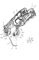
- FIG. 1 It is sectional drawing which shows the internal structure of the vibrating tool which concerns on 1st Embodiment of this invention.
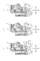
- A is a right side view showing the appearance of the housing and the tool holding portion of the vibrating tool according to the first embodiment of the present invention, and
- (b) is a sectional view taken along line BB of (a).
- C) is a sectional view taken along line CC of (b).
- FIG. 1 is a figure which shows the 3rd modification of the vibrating tool which concerns on 1st Embodiment of this invention, and is the figure for demonstrating the process of attaching and detaching a hexagon wrench to a tool holding part.
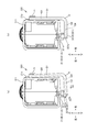
- A is a right side view showing the appearance of the housing and the tool holding portion of the vibrating tool according to the second embodiment of the present invention, and (b) is a sectional view taken along line BB of (a).
- (C) is a sectional view taken along line CC of (b). It is a figure for demonstrating the process of attaching and detaching the hexagon wrench to the tool holding part of the vibrating tool which concerns on 2nd Embodiment of this invention.
- (A) is a right side view showing the appearance of the housing and the tool holding portion of the vibrating tool according to the third embodiment of the present invention, and (b) is a sectional view taken along line BB of (a).
- (C) is a sectional view taken along line CC of (b). It is a figure for demonstrating the process of attaching and detaching the hexagon wrench to the tool holding part of the vibrating tool which concerns on 3rd Embodiment of this invention.
- (A) is a right side view showing the appearance of the housing and the tool holding portion of the vibrating tool according to the fourth embodiment of the present invention, and (b) is a sectional view taken along line BB of (a).
- FIG. 1 is a diagram for explaining the process of attaching and detaching the chuck handle to the tool holding portion of the screwdriver according to the fifth embodiment of the present invention, and (b) is a cross section taken along line BB of (a). It is a figure. It is a figure for demonstrating the process of attaching and detaching a hexagon wrench to the tool holding part of the vibration tool of the conventional example.
- the vibration tool 1 which is an example of the power tool according to the first embodiment of the present invention will be described with reference to FIGS. 1 to 7.
- the vibrating tool 1 is a power tool that grinds, cuts, cuts, etc., the work material by driving (vibrating) the tip tool P.
- the vibration tool 1 has a housing 2 to which the battery pack B can be attached and detached, a motor 3, a control unit 4, a power transmission unit 5, and a tip tool P to be attached and detached. It mainly has an output shaft portion 6 and a tool holding portion 7.
- the housing 2 mainly has a main body housing 21 and a holder 22.
- the housing 2 is an example of the "housing" in the present invention.
- the main body housing 21 forms the outer shell of the vibrating tool 1 and has a substantially cylindrical shape extending in the front-rear direction. As shown in FIG. 3, the main body housing 21 is configured as a divided housing divided by a divided surface (virtual surface) that passes through substantially the center of the housing 2 in the left-right direction and is orthogonal to the left-right direction.
- the main body housing 21 houses the motor 3, the control unit 4, the power transmission unit 5, and the upper part of the output shaft unit 6.
- the diameter of the substantially central portion of the main body housing 21 in the front-rear direction is configured to be large enough for the operator to grasp during the work.
- the main body housing 21 is provided with a slide switch 21A, a slide bar 21B, a battery mounting portion 21C, a recess 21D, and a pair of regulating portions 21G (FIG. 3).
- the slide switch 21A is provided on the upper part of the front portion of the main body housing 21.
- the slide switch 21A is provided on the outer wall of the main body housing 21, and the operator can operate the slide switch 21A from the outside.
- the slide switch 21A moves in the front-rear direction by being operated from the outside.
- the slide bar 21B is housed in the main body housing 21, and its front end is connected to the lower surface of the slide switch 21A. As a result, the slide bar 21B can move in the front-rear direction as the slide switch 21A moves in the front-rear direction. In other words, the slide bar 21B moves forward integrally with the slide switch 21A when the slide switch 21A moves forward, and moves backward integrally with the slide switch 21A when the slide switch 21A moves backward. Move to.
- the recess 21D is provided at the rear of the main body housing 21.
- the recess 21D is formed so as to be recessed inward of the main body housing 21 from the outer peripheral surface of the main body housing 21.
- a boss 21F is provided in the recess 21D.
- the boss 21F is provided at a position overlapping the recess 21D in the left-right direction view. Specifically, the boss 21F extends in the left-right direction in the space defined by the recess 21D recessed inward of the main body housing 21.
- the boss 21F is an example of a "protrusion" in the present invention.
- a groove 21a is formed in the rear portion of the main body housing 21.
- the groove 21a is formed so as to extend in the vertical direction and to be recessed inward of the main body housing 21 with a predetermined curvature.
- a convex portion 21H protruding to the right in a rectangular shape is provided at the lower portion of the arcuate peripheral surface forming the groove 21a.
- the pair of regulating portions 21G are provided so as to project to the right from the main body housing 21.
- the pair of regulating portions 21G are provided symmetrically with the groove 21a interposed therebetween.
- the holder 22 shown in FIG. 1 is made of a metal alloy and is supported by the main body housing 21.
- the holder 22 rotatably supports the output shaft portion 6 via a bearing.
- the motor 3 shown in FIG. 1 is a brushed motor and has a rotating shaft 31.
- the rotation shaft 31 is rotatable about an axis A extending in the front-rear direction.
- the axis A is a line extending in the front-rear direction and passing through the axis of the rotating shaft 31.
- the motor 3 is an example of the "motor" in the present invention.
- control unit 4 mainly includes a control box 41, a main switch 42, and a speed adjustment dial 43.
- the control box 41 has a substantially rectangular parallelepiped shape with an open front, and is housed in the rear portion of the main body housing 21 so that its shortest side is parallel to the front-rear direction. Although not shown in the figure, the control box 41 houses a substrate on which a control circuit for controlling the motor 3 is mounted.
- the main switch 42 is connected to the rear end of the slide bar 21B of the main body housing 21.
- the main switch 42 is electrically connected to the control box 41 via a signal cable.
- the main switch 42 sends a tool start signal for starting the motor 3 when the slide switch 21A is pulled in a predetermined direction, that is, started (for example, when the slide switch 21A is slid backward by the operator's finger). It is configured to output to. Further, the main switch 42 stops the output of the tool start signal when the slide switch is pulled or released in the direction opposite to the predetermined direction (for example, when the slide switch is slid forward by the operator's finger). It is configured as follows.
- the speed adjustment dial 43 is a mechanism for setting a target rotation speed of the motor 3, and is provided on the upper portion of the rear portion of the main body housing 21.
- the speed adjustment dial 43 is configured to be operable from the outside by an operator.
- the speed adjustment dial 43 is electrically connected to the substrate housed in the control box 41 via a signal cable.
- the power transmission unit 5 is connected to the rotation shaft 31 of the motor 3 and mainly has a spindle 51, a bearing 52, and a swing arm 53.
- the spindle 51 extends in the front-rear direction.
- the spindle 51 is rotatably supported by the holder 22 via a bearing.
- the front end portion of the rotating shaft 31 is fitted to the rear portion of the spindle 51.
- the spindle 51 can rotate about the axis A integrally with the rotating shaft 31.
- the spindle 51 has an eccentric shaft 51A.
- the eccentric shaft 51A forms a front end portion of the spindle 51 and has a substantially cylindrical shape extending in the front-rear direction.
- the eccentric shaft 51A is configured to have a diameter smaller than the diameter of other parts of the spindle 51, and the axis B passing through the axis is slightly deviated from the axis A.
- the bearing 52 is provided on the eccentric shaft 51A.
- the inner ring of the bearing 52 is fixed to the eccentric shaft 51A.
- the swing arm 53 has a cylindrical portion 53A and an arm portion 53B.
- the cylindrical portion 53A has a substantially cylindrical shape extending in the vertical direction.
- the inner peripheral surface of the cylindrical portion 53A is fixed to the output shaft portion 6.
- the arm portion 53B has a substantially U-shape that opens rearward in a top view.
- the arm portion 53B is in contact with the outer ring of the bearing 52. That is, the outer ring of the bearing 52 is sandwiched by the arm portion 53B from the left-right direction.
- the swing arm 53 swings around the axis C.
- the axis C passes through the center of the output shaft portion 6 and is orthogonal to the axis A.
- the output shaft portion 6 is supported by the main body housing 21 and has an output shaft 61 and a hexagon socket head screw 62.
- the output shaft portion 6 is an example of the “tip tool attachment / detachment portion” in the present invention.
- the output shaft 61 has a substantially cylindrical shape extending in the vertical direction.
- a female screw hole 61a extending in the vertical direction is formed in the lower portion of the output shaft 61.
- the output shaft 61 has a plurality of protrusions 61A.
- the plurality of protrusions 61A project downward from the lower surface of the output shaft 61.
- the plurality of protrusions 61A are provided at substantially equal intervals in the circumferential direction of the output shaft 61.
- the hexagon socket head screw 62 is a male screw, and a hexagonal hole 62a is formed in the head thereof.
- the tip tool P is sandwiched between the head of the hexagon socket head screw 62 and the lower portion of the output shaft 61 to sandwich the plate-shaped tip tool P. It is configured so that it can be held by the output shaft portion 6.
- the tip tool P is formed with a groove into which a plurality of protrusions 61A of the output shaft 61 can be engaged.
- the tip tool P is held by the output shaft portion 6 by being sandwiched between the lower surface of the output shaft 61 and the upper surface of the hexagon socket head screw 62 in a state where a plurality of protrusions 61A are engaged with the groove.
- hexagon wrench Q which is an example of the tool holding portion 7 and the replacement tool that can be attached to and detached from the tool holding portion 7, will be described.
- the tool holding portion 7 is provided in the main body housing 21 and is configured to be able to hold the hexagon wrench Q. As shown in FIGS. 1 to 3, the tool holding portion 7 has a first holding portion 71 and a second holding portion 72.
- the tool holding portion 7 is an example of the “tool holding portion” in the present invention.
- the first holding portion 71 is formed in a substantially semi-cylindrical shape extending in the vertical direction, and is provided integrally with the main body housing 21 at the rear portion of the main body housing 21. Specifically, it is provided so as to cover the arcuate peripheral surface forming the groove 21a from the right side.
- the curvature of the inner peripheral surface of the first holding portion 71 and the curvature of the arcuate peripheral surface forming the groove 21a are configured to be the same. Therefore, in the region where the first holding portion 71 is provided, a substantially cylindrical surface extending in the vertical direction is defined by the peripheral surface forming the groove 21a and the inner peripheral surface of the first holding portion.
- the first holding portion 71 is an example of the “first holding portion” in the present invention.
- the second holding portion 72 is provided at a position different from that of the first holding portion, and is configured to be able to hold the hexagon wrench Q in cooperation with the first holding portion 71.
- the second holding portion 72 is an elastic body such as a thermosetting resin having high heat resistance, and is configured separately from the main body housing 12.
- the second holding portion 72 is formed in a substantially flat shape in which the length in the left-right direction is shorter than the length in the front-rear direction and the up-down direction. Further, the second holding portion 72 is formed so as to be slightly tapered toward the lower side. That is, the length of the upper portion of the second holding portion 72 in the front-rear direction is longer than the length of the lower portion in the front-rear direction. Further, as shown in FIG.
- the shape of the upper end of the second holding portion 72 is formed to be the same as the recessed shape of the recess 21D of the main body housing 21. As shown in FIGS. 1 and 3, the upper portion of the second holding portion 72 is housed in the recess 21D of the main body housing 21. As a result, the second holding portion 72 is configured to suppress deformation of the main body housing 21 more than necessary.
- the second holding portion 72 has a held portion 72A and a holding portion 72B.
- the second holding portion 72 is an example of the “second holding portion” in the present invention.
- the held portion 72A forms the upper part of the second holding portion 72, and the first hole 72a is formed.
- the first hole 72a penetrates the held portion 72A in the left-right direction.
- the inner diameter of the first hole 72a is slightly smaller than the outer diameter of the boss 21F of the main body housing 21, and the boss 21F is inserted through the first hole 72a.
- the held portion 72A is formed with a first hole 72a that opens in the projecting direction of the boss 21F and receives and fixes the boss 21F. According to such a configuration, the second holding portion 72 provided separately from the main body housing 21 can be easily fixed to the main body housing 21.
- the held portion 72A is housed in the recess 21D, and the boss 21F is inserted into the first hole 72a, so that the second holding portion 72 is deformed more than necessary with respect to the main body housing 21. Is configured to be regulated.
- the held portion 72A is an example of the “held portion” in the present invention.
- the first hole 72a is an example of the "first opening" in the present invention.
- the holding portion 72B forms a lower portion of the second holding portion 72, and a second hole 72b is formed.
- the second hole 72b penetrates the holding portion 72B in the left-right direction. In other words, the second hole 72b extends in the same direction as the first hole 72a. Therefore, it becomes easy to form the first hole 72a and the second hole 72b in the second holding portion 72 in the tool holding portion 7 produced as an integrated product (single part), and the manufacturing cost of the tool holding portion 7 is reduced. It becomes possible.
- the inner diameter of the second hole 72b is slightly larger than the inner diameter of the first hole 72a.
- the holding portion 72B is an example of the "holding portion” in the present invention.
- the second hole 72b is an example of the "second opening" in the present invention.
- both the first hole 72a and the second hole 72b are formed so as to penetrate the second holding portion 72 in the left-right direction.
- at least one of the first hole 72a and the second hole 72b may be formed in a bottomed shape having an opening in either the right portion or the left portion of the tool holding portion 7.
- the hexagon wrench Q has a first axis Q1 and a second axis Q2.
- the first axis Q1 and the second axis Q2 extend in a direction intersecting each other.
- the first axis Q1 and the second axis Q2 extend in directions orthogonal to each other.
- the hexagon wrench Q has a substantially L shape.
- the outer diameter of the first shaft Q1 is slightly smaller than the inner diameter of the first holding portion 71.
- the outer diameter of the second shaft Q2 is configured to be slightly larger than the inner diameter of the second hole 72b of the second holding portion 72. Therefore, the second shaft Q2 is held so as to be press-fitted into the second hole 72b.
- each of the first axis Q1 and the second axis Q2 has an axis Q3 and an axis Q4.
- the first axis Q1 is an example of the "first axis portion" in the present invention
- the second axis Q2 is an example of the "shaft portion" and the "second axis portion” in the present invention.
- the first axis Q1 is an example of the "first replacement tool axis”
- the second axis Q2 is an example of the "second replacement tool axis”.
- the axial center Q3 extends in the vertical direction while the hexagon wrench Q is held by the tool holding portion 7. Further, in a state where the hexagon wrench Q is held by the tool holding portion 7, the axis Q4 extends in the left-right direction.
- the vertical direction is an example of the "first direction” in the present invention
- the horizontal direction is an example of the "second direction” in the present invention.
- the operator inserts the first axis Q1 of the hexagon wrench Q into the first holding portion 71. Specifically, the operator brings the tip of the first shaft Q1 closer to the first holding portion 71 from below along the groove 21a, and inserts the first shaft Q1 into the first holding portion 71.
- the first holding portion 71 accommodates a part of the first axis Q1 of the hexagon wrench Q (see FIG. 4A). .. That is, in the present embodiment, the hexagon wrench Q can be easily held by the first holding portion 71 by relatively moving the first holding portion 71 and the hexagon wrench Q.
- the movement of the hexagon wrench Q in the direction orthogonal to the vertical direction (movement of the first holding portion 71 in the radial direction) is restricted. Further, the first holding portion 71 allows the hexagon wrench Q to move in the vertical direction with respect to the main body housing 21 in a state where the first shaft Q1 is held by the first holding portion 71, and the first shaft of the hexagon wrench Q. Allows rotation around the axis Q3 of Q1.
- the outer peripheral surface of the first shaft Q1 and the convex portion 21H provided on the main body housing 21 are configured to come into contact with each other. Therefore, the hexagon wrench Q and the main body housing 21 do not rub against each other more than necessary. This makes it possible to suppress wear of the main body housing 21 due to contact with the hexagon wrench Q.
- the operator puts the hexagon wrench Q on the axis Q3 of the first axis Q1 so that the axis Q4 of the second axis Q2 coincides with the left-right direction. Is rotated around.
- the operator tilts the second holding portion 72 to the left as shown in FIG. 4 (b).
- the holding portion 72B forming the lower portion of the second holding portion 72 is rotated in the clockwise direction (direction opposite to the direction indicated by the arrow X3) in FIG. 4 (b).
- the second holding portion 72 is an elastic body such as a thermosetting resin
- the holding portion 72B is supported by the recess 21D and has the held portion 72A which forms the upper part of the second holding portion 72 as a fulcrum. It can be deformed as if it rotates suitably.
- the position of the second holding portion 72 in the state of being rotated in the clockwise direction in FIG. 4B by receiving an external force is referred to as a “retracted position”.
- the retracted position is a position where the second axis Q2 and the holding portion 72B are separated from each other.
- the second holding portion 72 in the retracted position is less restricted to move the hexagon wrench Q in the vertical direction (particularly downward).
- the positions of the second shaft Q2 and the holding portion 72B of the second holding portion 72 in the front-rear direction of the second hole 72b are the same.
- the operator inserts the second axis Q2 from the tip thereof into the second hole 72b as shown by the arrow X2 in FIG. 4 (b).
- the second holding portion 72 rotates the holding portion 72B in the counterclockwise direction (direction indicated by the arrow X3) in FIG. 4B due to its own elastic restoring force.
- the operator can suitably insert the second shaft Q2 into the second hole 72b.
- the holding position is a position where the vertical movement of the hexagon wrench Q with respect to the main body housing 21 and the rotation of the first axis Q1 about the axis Q3 can be regulated with respect to the main body housing 21.
- the second holding portion 72 can move between the holding position and the retracting position with respect to the main body housing 21 with a simple configuration by its own elastic restoring force.
- the second holding portion in a state where the hexagon wrench Q is held by the tool holding portion 7, the second holding portion is below the axis Q4 of the second shaft Q2. It is configured so that a part of 72 is located. That is, in a state where the hexagon wrench Q is held by the tool holding portion 7, the axial center Q4 of the second axis Q2 and the second holding portion 72 are configured to overlap in the vertical direction. Therefore, in a state where the movement of the hexagon wrench Q in the direction orthogonal to the vertical direction is restricted by the first holding unit 71, the movement of the hexagon wrench Q in the vertical direction is restricted by the second holding unit 72. As a result, even if the main body housing 21 vibrates during the work, it is possible to prevent the hexagon wrench Q from falling off from the tool holding portion 7.
- the holding portion 72B surrounds a part of the second axis Q2 in the left-right direction over the entire circumferential direction while the hexagon wrench Q is held by the tool holding portion 7. I'm out. As a result, it is possible to prevent the hexagon wrench Q from falling off from the tool holding portion 7.
- the holding portion 72B is configured to be movable relative to the main body housing 21, the holding portion 72B surrounds a part of the second axis Q2 over the entire circumferential direction as in the present embodiment.
- the hexagon wrench Q can be attached to and detached from the second holding portion 72 by moving the holding portion 72B relative to the main body housing 21.
- the second holding portion 72 restricts the vertical movement of the hexagon wrench Q with respect to the main body housing 21 in a state where the first shaft Q1 is held by the first holding portion 71, and also regulates the movement of the hexagon wrench Q in the vertical direction.
- the hexagon wrench Q is configured to regulate the rotation of the first axis Q1 about the axis Q3. Therefore, in a state where the hexagon wrench Q is held by the tool holding portion 7, it is possible to suppress the rotation of the hexagon wrench Q in the tool holding portion 7 and the detachment from the tool holding portion 7.
- the hexagon wrench Q can be held by the second holding portion 72 by moving the holding portion 72B of the second holding portion 72 relative to the housing in the left-right direction.
- the hexagon wrench Q is moved by moving the holding portion 72B in a horizontal direction different from the vertical direction in which the hexagon wrench Q is moved when the first holding portion 71 holds the first axis Q1. Can be held by the second holding portion 72. Therefore, it is possible to suitably prevent the hexagon wrench Q from falling off from the power tool body.
- the direction in which the second hole 72b of the holding portion 72B opens at the holding position shown in FIG. 4C is different from the direction in which the second hole 72b opens at the retracting position shown in FIG. 4B. There is. According to such a configuration, by changing the opening direction of the second hole 72b, the restricted state of movement of the second holding portion 72 with respect to the hexagon wrench Q can be changed, and the hexagon wrench Q can be easily attached and detached. Will be.
- the pair of regulating portions 21G of the main body housing 21 are positioned so as to sandwich the first axis Q1 from the front-rear direction. doing. Therefore, it is possible to suppress rattling of the hexagon wrench Q with respect to the main body housing.
- the tool holding portion 7 in a state where the hexagon wrench Q is held by the tool holding portion 7, at least a part of the first holding portion 71 is in the left-right direction with the axis Q3 of the first axis Q1 of the hexagon wrench Q.
- at least a part of the second holding portion 72 overlaps with the axis Q4 of the second axis Q2 in the vertical direction.
- the tool holding portion 7 is configured to be able to regulate the movement of the hexagon wrench Q from the vibration tool 1 main body in the two directions of the first direction and the second direction intersecting the first direction.
- the operator moves the hexagon wrench Q downward.
- the state in which the first shaft Q1 is inserted into the first holding portion 71 is released, and the hexagon wrench Q can be removed from the main body housing 21.
- the operator When removing the tip tool P from the output shaft portion 6, the operator engages the tip portion of the first shaft Q1 or the second shaft Q2 of the hexagon wrench Q with the hexagonal hole 62a of the hexagon socket head screw 62 of the output shaft portion 6. Match. Next, the operator rotates the hexagon wrench Q in the direction of loosening the screw of the hexagon socket head screw 62 with respect to the output shaft 61 of the output shaft portion 6. As a result, the state in which the tip tool P is sandwiched between the lower surface of the output shaft 61 and the upper surface of the head of the hexagon socket head screw 62 is released, and the tip tool P can be removed from the output shaft portion 6.
- the operator is first formed on the tip tool P so as to correspond to the plurality of protrusions 61A provided on the lower surface of the output shaft 61 and the plurality of protrusions 61A. Engage with multiple grooves.
- the operator engages the tip of the first axis Q1 or the second axis Q2 of the hexagon wrench Q with the hexagonal hole 62a.
- the hexagon wrench Q is rotated so that the hexagon socket head screw 62 is screwed into the female screw hole 61a of the output shaft 61.
- the tip tool P can be attached to the output shaft portion 6.
- the rotating shaft 31 and the spindle 51 rotate integrally.
- the eccentric shaft 51A and the bearing 52 revolve around the axis A.
- the swing arm 53 reciprocates and swings within a range of a predetermined angle with the output shaft 61 as a fulcrum.
- the distance from the axis A in the front view to the outer peripheral surface of the eccentric shaft 51A located substantially to the right or substantially to the left is changed.
- the swing arm 53 swings around the axis C.
- the output shaft 61 alternately repeats forward rotation and reverse rotation within a range of a predetermined angle about the axis C. In this way, the rotational force of the motor 3 is converted into a rotational force within a range of a predetermined angle of the output shaft 61.
- the tip tool P When the output shaft 61 rotates forward and backward within a predetermined angle range, the tip tool P also swings within a predetermined angle range around the axis C. Then, when the tip tool P is pressed against the object, the object can be processed, for example, polished.
- the vibration tool 900 As shown in FIG. 15, the vibration tool 900 according to the conventional example has a housing 91 and a tool holding portion 92.
- the tool holding portion 92 is formed integrally with the housing 91.
- the tool holding portion 92 is an elastic body such as a thermoplastic resin having a lower heat resistance than a thermosetting resin or the like.
- the tool holding portion 92 is configured as a pair of members protruding from the housing 91.
- the tool holding portion 92 extends in a direction orthogonal to the paper surface of FIG.
- the tool holding portion 92 is provided with a pair of regulating portions 92A.
- the pair of restricting portions 92A are provided at the protruding ends of the pair of ribs constituting the tool holding portion 92, and extend in a direction orthogonal to the paper surface of FIG.
- the opening 92a is formed by the protruding ends of the pair of regulating portions 92A.
- the tool holding portion 92 is configured to be able to hold the hexagon wrench Z.
- the hexagon wrench Z has a shaft portion having an axis Z1 extending in a direction orthogonal to the paper surface while being held by the tool holding portion 92.
- the diameter of the shaft portion is configured to be larger than the distance between the pair of regulating portions 92A on the paper surface.
- the operator press-fits the shaft portion of the hexagon wrench Z into the tool holding portion 92 from the right side of the paper surface as shown in FIGS. 15A to 15D.
- the hexagon wrench Z is made to enter the tool holding portion 92 while elastically deforming the pair of regulating portions 92A through the opening 92a. ..
- the hexagon wrench Z may fall off through the opening 92a due to the vibration generated in the housing 91 during the work.
- the tool holding portion 92 is a thermoplastic elastic body, it is worn and deteriorated by repeatedly attaching and detaching the hexagon wrench Z, and the fitting force is weakened.
- the elastic deformation direction of the regulating portion 92A applied when the hexagon wrench Z is attached and when it is removed is different, the amount of deformation of the regulating portion 92A in a series of flows becomes large, and accordingly. Therefore, the load applied to the regulation unit 92A at the time of attachment / detachment also increases.
- the hexagon wrench Z may fall off through the opening 92a. That is, in the vibration tool 900 according to the conventional example, when the hexagon wrench Z is moved in the left-right direction to be attached to and detached from the tool holding portion 92, the opening 92a is formed in the attachment / detachment direction (left-right direction), so that the fitting is made. There is a high possibility that the hexagon wrench Z will fall off due to a decrease in fitting force or the like.
- the operator moves the hexagon wrench Q with respect to the first holding portion 71 to move the hexagon wrench Q to the first holding portion 71.
- the axis Q4 of the second axis Q2 and the second holding portion 72 are configured to overlap each other in the vertical view. Therefore, in a state where the movement of the hexagon wrench Q in the direction orthogonal to the vertical direction is restricted by the first holding portion 71, the movement of the hexagon wrench Q in the vertical direction is restricted by the second holding portion 72. This makes it possible to prevent the tool from falling off from the tool holding portion even when vibration is generated in the power tool main body during work.
- the elastic deformation direction of the second holding portion 72 applied when the hexagon wrench Q is attached / detached is one direction, and the amount of deformation can be suppressed, so that deterioration of the second holding portion 72 can be suppressed.
- the holding portion 72B surrounds a part of the second axis Q2 in the left-right direction over the entire circumferential direction in a state where the hexagon wrench Q is held by the tool holding portion 7. As a result, it is possible to prevent the hexagon wrench Q from falling off from the tool holding portion 7.
- the holding portion 72B is configured to be movable relative to the main body housing 21, the holding portion 72B surrounds a part of the second axis Q2 over the entire circumferential direction as in the present embodiment.
- the hexagon wrench Q can be attached to and detached from the second holding portion 72 by moving the holding portion 72B relative to the main body housing 21.
- the tool holding portion 92 is a thermoplastic elastic body having low heat resistance, it is generated between the hexagon wrench Z and the tool holding portion 92 due to vibration generated in the housing 91 during work. There was a possibility that the tool holding portion 92 would melt due to the friction caused and the tool holding portion 92 would not function.
- the second holding portion 72 is a thermosetting elastic body having high heat resistance. Therefore, it is suppressed that the second holding portion 72 is welded to other members. Further, in the present embodiment, as shown in FIG. 4C, the surface and the second surface forming the second hole 72b of the holding portion 72B in the state where the hexagon wrench Q is held by the tool holding portion 7. It is in close contact with the shaft Q2. Further, the holding portion 72B can move relative to the main body housing 21. Therefore, even when the vibration tool 1 main body vibrates and the hexagon wrench Q rattles relative to the main body housing 21, the holding portion 72B can follow the movement of the hexagon wrench Q. Therefore, the occurrence of friction between the hexagon wrench Q and the holding portion 72B is suppressed.
- the vibrating tool 1 may have a tool holding portion 17 instead of the tool holding portion 7.
- the tool holding portion 17 has a second holding portion 172 instead of the second holding portion 72.
- the second holding portion 172 is an elastic body such as a thermosetting resin having high heat resistance.
- the second holding portion 172 has a held portion 172A and a holding portion 172B. Since the held portion 172A has the same configuration as the held portion 72A according to the first embodiment, the description thereof will be omitted.
- the tool holding portion 17 is an example of the “tool holding portion” in the present invention.
- the second holding portion 172 is an example of the "second holding portion” in the present invention.
- the held portion 172A is an example of the "held portion” in the present invention
- the holding portion 172B is an example of the "holding portion” in the present invention.
- the holding portion 172B is formed with a groove 172b that opens in front of the holding portion 172B and extends in the front-rear direction. Further, the holding portion 172B is provided with a valve portion 172C protruding inward of the groove 172b.
- the operator centers the hexagon wrench Q on the axis Q3 of the first axis Q1 while the first axis Q1 of the hexagon wrench Q is held by the first holding portion 71.
- the second axis Q2 passes through the valve portion 172C while elastically deforming the valve portion 172C and enters the depth of the groove 172a.
- the shape of the valve portion 172C of the second axis Q2 returns to the shape before elastic deformation.
- FIG. 5C the rotation of the hexagon wrench Q around the axis Q3 of the first axis Q1 is restricted.
- the axial center Q4 of the second shaft portion Q2 and the second holding portion 172 are configured to overlap each other in the vertical view. .. Therefore, in a state where the movement of the hexagon wrench Q in the direction orthogonal to the vertical direction is restricted by the first holding unit 71, the movement of the hexagon wrench Q in the vertical direction is restricted by the second holding unit 172. As a result, even if the vibration tool 1 main body vibrates during the work, it is possible to prevent the hexagon wrench Q from falling off from the tool holding portion 17.
- the second holding portion 172 is elastically deformed to the left and moved to the retracted position in the same manner as the second holding portion 72 described above. The wrench Q can be removed.
- the vibrating tool 1 may have a tool holding portion 27 instead of the tool holding portion 7.
- the tool holding portion 27 has a second holding portion 272 instead of the second holding portion 72.
- the tool holding portion 27 is an example of the “tool holding portion” in the present invention.
- the second holding portion 272 is an example of the "second holding portion” in the present invention.
- the second holding portion 272 is an elastic body such as a thermosetting resin having high heat resistance.
- the outer shape of the second holding portion 272 is formed to be substantially the same as the outer shape of the second holding portion 72.
- the second holding portion 272 is formed with a through hole 272a that penetrates the second holding portion 272 in the left-right direction.
- the through hole 272a is formed in a substantially elliptical shape having a long axis extending in the vertical direction in the horizontal view.
- the boss 21F of the recess 21D of the main body housing 21 is inserted into the through hole 272a.
- the operator tilts the second holding portion 272 to the left as shown in FIG. 6 (b). Specifically, the holding portion 272B forming the lower portion of the second holding portion 272 is rotated in the clockwise direction (direction opposite to the direction indicated by the arrow X5) in FIG. 6 (b). That is, the second holding portion 272 is rotated so as to be located at the retracted position.
- the second holding portion 272 is an elastic body such as a thermosetting resin, the lower portion of the second holding portion 272 is deformed as if it is suitably rotated with the upper portion of the second holding portion 272 as a fulcrum. It is possible to do.
- the operator inserts the second axis Q2 from the tip thereof into the through hole 272a as shown by the arrow X4 in FIG. 6 (b).
- the second holding portion 272 is deformed as if it were rotated toward the holding position due to its own elastic restoring force.
- the operator can insert the second shaft Q2 into the through hole 272a.
- the axial center Q4 of the second shaft portion Q2 and the second holding portion 272 are configured to overlap each other in the vertical view. .. Therefore, in a state where the movement of the hexagon wrench Q in the direction orthogonal to the vertical direction is restricted by the first holding unit 71, the movement of the hexagon wrench Q in the vertical direction is restricted by the second holding unit 272. As a result, even if the vibration tool 1 main body vibrates during the work, it is possible to prevent the hexagon wrench Q from falling off from the tool holding portion 17.
- the second holding portion 272 cooperates with the boss 21F of the recess 21D of the main body housing 21 in a state where the hexagon wrench Q is held by the tool holding portion 27, and is left and right. A part of the second axis Q2 in the direction is surrounded over the entire circumferential direction. Therefore, it is possible to prevent the hexagon wrench Q from falling off from the tool holding portion 27. Further, since the second holding portion 272 is configured to be movable relative to the main body housing 21, the hexagon wrench Q can be easily attached to and detached from the second holding portion 272.
- the boss 21F and the second axis Q2 of the hexagon wrench Q can both be inserted through the through hole 272a, it is sufficient to form one through hole in the second holding portion 272, so that the second holding is performed in a simpler shape. It becomes possible to realize the part.
- the vibrating tool 1 may have a tool holding portion 37 instead of the tool holding portion 7.
- the tool holding portion 37 has a first holding portion 371 instead of the first holding portion 71.
- the first holding portion 371 has a first cylindrical portion 371A, a second cylindrical portion 371B, and an urging member 371C.
- the tool holding portion 37 is an example of the “tool holding portion” in the present invention.
- the first holding portion 371 is an example of the "first holding portion" in the present invention.
- the first cylindrical portion 371A is provided integrally with the main body housing 21, has an upper wall, and has a substantially bottomed cylindrical shape extending in the vertical direction.
- the second cylindrical portion 371B has a substantially cylindrical shape extending in the vertical direction.
- the outer diameter of the second cylindrical portion 371B is slightly smaller than the inner diameter of the first cylindrical portion 371A.
- the second cylindrical portion 371B is housed in the first cylindrical portion 371A so as to be slidable in the first cylindrical portion 371A in the vertical direction.
- the inner diameter of the second cylindrical portion 371B is configured to be slightly larger than the outer diameter of the first axis Q1 of the hexagon wrench Q.
- the second cylindrical portion 371B has a protruding portion 371D that projects inward in the radial direction from the inner peripheral surface thereof.
- the urging member 371C is a coil spring.
- the urging member 371C is arranged between the first cylindrical portion 371A and the second cylindrical portion 371B in the vertical direction. Specifically, the upper end of the urging member 371C is fixed to the lower surface of the upper wall of the first cylindrical portion 371A, and the lower end of the urging member 371C is fixed to the upper surface of the protruding portion 371D. As a result, the urging member 371C urges the second cylindrical portion 371B downward with respect to the first cylindrical portion 371A.
- the first axis Q1 of the hexagon wrench Q is held by the first holding portion 371 by accommodating the tip portion thereof in the second cylindrical portion 371B.
- the operator attaches the second cylindrical portion 371B to the urging member 371C as shown in FIG. 7 (b). Push up against.
- the second cylindrical portion 371B retracts upward, the state in which the second axis Q1 is held by the first holding portion 371 is released.
- the restriction on the rightward movement of the hexagon wrench Q by the first holding portion 371 is removed, so that the operator can remove the hexagon wrench Q from the tool holding portion 37.
- the second cylindrical portion 371B moves downward due to the urging force of the urging member 371C.
- the object held by the tool holding portion 7 is a hexagon wrench Q which is an example of a replacement tool, but the tool holding portion 7 may be configured to be able to hold the tip tool. .. According to such a configuration, by using the tool holding portion, it is possible to prevent the tip tool from falling off from the power tool main body when the tip tool is not used. In addition, the tip tool can be easily replaced.
- the tip tool that can be held by the tool holding portion may be configured to have a first tip tool shaft and a second tip tool shaft that extend in different directions.
- the tool holding portion is configured such that the first holding portion holds the first tip tool shaft and the second holding portion holds the second tip tool shaft. According to such a configuration, by using the tool holding portion, it is possible to prevent the tip tool having the first tip tool shaft and the second tip tool shaft extending in different directions from falling off from the power tool main body. Is possible.
- the vibrating tool 200 basically has the same configuration as the vibrating tool 1 according to the first embodiment, and the same reference number is assigned to the same configuration as the vibrating tool 1 and the description thereof is omitted as appropriate. , The different configurations will be mainly described. Further, with respect to the same configuration as the vibrating tool 1, the same effect as that described above is obtained.
- the vibration tool 200 according to the second embodiment has a housing 210 instead of the housing 2. Further, the vibrating tool 200 has a tool holding portion 220 instead of the tool holding portion 7.
- the housing 210 has a main body housing 211.
- the main body housing 211 forms an outer shell of the vibrating tool 200 and has a support portion 211A.
- the housing 210 is an example of a "housing" in the present invention.
- the support portion 211A has an opening at the lower portion thereof and has a substantially cylindrical shape extending in the left-right direction. Inside the support portion 211A, a boss 211B extending in the left-right direction is provided.
- the boss 211B is an example of a "protrusion" in the present invention.
- the tool holding portion 220 has an O-ring 221 instead of the second holding portion 72.
- the O-ring 221 is a substantially annular member, and is an elastic body such as a thermosetting resin having high heat resistance.
- the O-ring 221 is formed in a figure eight shape by deforming portions located on opposite sides in the radial direction inward in the radial direction, and is assembled to the main body housing 211. The portion of the O-ring 221 deformed inward in the radial direction is inserted through an opening formed in the lower portion of the support portion 211A. As shown in FIG.
- the O-ring 221 has a held portion 221A forming an upper portion thereof and a holding portion 221B forming a lower portion thereof in a state of being assembled to the main body housing 211. ..
- the first hole 221a is formed by the inner peripheral surface of the held portion 221A
- the second hole 221b is formed by the inner peripheral surface of the holding portion 221B.
- the O-ring 221 is supported by the support portion 211A by inserting the boss 211B into the first hole 221a.
- the tool holding portion 220 is an example of the "tool holding portion” in the present invention.
- the O-ring 221 is an example of the "second holding portion" in the present invention.
- the held portion 221A is an example of the "held portion” in the present invention
- the holding portion 221B is an example of the "holding portion” in the present invention
- the first hole 221a is an example of the "first opening” in the present invention
- the second hole 221b is an example of the "second opening” in the present invention.
- the operator tilts the holding portion 221B of the O-ring 221 to the left as shown in FIG. 9A.
- the holding portion 221B is rotated in the clockwise direction of FIG. 9A (the direction opposite to the direction indicated by the arrow X7). That is, the O-ring 221 is rotated so as to be located at the retracted position.
- the O-ring 221 is an elastic body such as a thermosetting resin, the holding portion 221B can be deformed as if it were suitably rotated with the held portion 221A as a fulcrum.
- the operator inserts the second axis Q2 from the tip thereof into the second hole 221b as shown by the arrow X6 in FIG. 9B.
- the O-ring 221 is deformed as if it were rotated toward the holding position by its own elastic restoring force.
- the operator can insert the second shaft Q2 into the second hole 221b.
- the axis Q4 of the second axis Q2 and the O-ring 221 overlap each other in the bottom view. It is configured in. That is, in a state where the hexagon wrench Q is held by the tool holding portion 220, the axial center Q4 of the second axis Q2 and the O-ring 221 are configured to overlap in the vertical direction. Therefore, in a state where the movement of the hexagon wrench Q in the direction orthogonal to the vertical direction is restricted by the first holding portion 71, the movement of the hexagon wrench Q in the vertical direction is restricted by the O-ring 221. As a result, even if vibration is generated in the main body housing 21 during the work, it is possible to prevent the hexagon wrench Q from falling off from the tool holding portion 220.
- the holding portion 221B surrounds a part of the second axis Q2 in the left-right direction over the entire circumferential direction while the hexagon wrench Q is held by the tool holding portion 220. I'm out. As a result, it is possible to prevent the hexagon wrench Q from falling off from the tool holding portion 220.
- the holding portion 221B is configured to be movable relative to the main body housing 211, the holding portion 221B surrounds a part of the second axis Q2 over the entire circumferential direction as in the present embodiment.
- the O-ring is a part that is also used as a sealing member, and various sizes can be manufactured at low cost. Therefore, in the case of this embodiment, a cheaper power tool can be realized.
- the vibrating tool 300 basically has the same configuration as the vibrating tool 1 according to the first embodiment, and the same reference number is assigned to the same configuration as the vibrating tool 1 and the description thereof is omitted as appropriate. , The different configurations will be mainly described. Further, with respect to the same configuration as the vibrating tool 1, the same effect as that described above is obtained.
- the vibrating tool 300 has a housing 310 instead of the housing 2. Further, the vibrating tool 300 has a tool holding portion 320 instead of the tool holding portion 7.
- the housing 310 has a main body housing 311.
- the main body housing 311 forms an outer shell of the vibrating tool 300 and has a support portion 311A.
- the housing 310 is an example of a "housing" in the present invention.
- the support portion 311A has an opening at the lower portion thereof and has a substantially cylindrical shape extending in the left-right direction. Inside the support portion 311A, a boss 311B extending in the left-right direction is provided.
- the boss 311B is an example of a "protrusion" in the present invention.
- the tool holding portion 320 has a string 321 made of heat-resistant fibers.
- the string 321 is formed in an endless shape having a width in the left-right direction.
- the string 321 is formed in a figure eight shape by deforming portions located on opposite sides in the radial direction inward in the radial direction, and is assembled to the main body housing 311.
- the portion of the string 321 deformed inward in the radial direction is inserted through an opening formed in the lower part of the support portion 311A.
- the string 321 has a held portion 321A forming an upper portion thereof and a holding portion 321B forming a lower portion thereof in a state of being assembled to the main body housing 311.
- the first hole 321a is formed by the inner peripheral surface of the held portion 321A
- the second hole 321b is formed by the inner peripheral surface of the holding portion 321B.
- the string 321 is supported by the support portion 311A by inserting the boss 311B into the second hole 321b.
- the tool holding portion 320 is an example of the “tool holding portion” in the present invention.
- the string 321 is an example of the "second holding portion” in the present invention.
- the held portion 321A is an example of the "held portion” in the present invention
- the holding portion 321B is an example of the "holding portion” in the present invention.
- the first hole 321a is an example of the "first opening” in the present invention
- the second hole 321b is an example of the "second opening” in the present invention.
- the operator tilts the holding portion 321B of the string 321 to the left as shown in FIG. 11A.
- the holding portion 321B is rotated in the clockwise direction of FIG. 11A (the direction opposite to the direction indicated by the arrow X9). That is, the string 321 is rotated so as to be located at the retracted position.
- the operator inserts the second axis Q2 from the tip thereof into the second hole 321b as shown by the arrow X8 in FIG. 11B.
- the operator rotates the holding portion 321B in the counterclockwise direction of FIG. 11A as shown by the arrow X9.
- the axis Q4 of the second axis Q2 and the string 321 overlap each other in the bottom view. It is configured. That is, in a state where the hexagon wrench Q is held by the tool holding portion 320, the axis Q4 of the second axis Q2 and the string 321 are configured to overlap in the vertical direction. Therefore, in a state where the movement of the hexagon wrench Q in the direction orthogonal to the vertical direction is restricted by the first holding portion 71, the movement of the hexagon wrench Q in the vertical direction is restricted by the string 321. As a result, even if the main body housing 21 vibrates during the work, it is possible to prevent the hexagon wrench Q from falling off from the tool holding portion 320.
- the holding portion 321B surrounds a part of the second axis Q2 in the left-right direction over the entire circumferential direction in a state where the hexagon wrench Q is held by the tool holding portion 320. I'm out. As a result, it is possible to prevent the hexagon wrench Q from falling off from the tool holding portion 320.
- the holding portion 321B is configured to be movable relative to the main body housing 311 so that the holding portion 321B surrounds a part of the second axis Q2 over the entire circumferential direction as in the present embodiment.
- the hexagon wrench Q can be attached to and detached from the string 321 by moving the holding portion 321B relative to the main body housing 311.
- the holding portion 321B can be easily moved relative to the main body housing 311 as compared with the case where an elastic body is used for the tool holding portion. It becomes.
- the vibrating tool 400 which is an example of the power tool according to the fourth embodiment of the present invention, will be described with reference to FIGS. 12 and 13.
- the vibrating tool 400 basically has the same configuration as the vibrating tool 1 according to the first embodiment, and the same reference number is assigned to the same configuration as the vibrating tool 1 and the description thereof is omitted as appropriate. , The different configurations will be mainly described. Further, with respect to the same configuration as the vibrating tool 1, the same effect as that described above is obtained.
- the vibrating tool 400 according to the fourth embodiment has a housing 410 instead of the housing 2.
- the vibrating tool 400 has a tool holding portion 420 instead of the tool holding portion 7. Further, the vibration tool 400 has a torsion spring 421G.
- the housing 410 has a main body housing 411.
- the main body housing 411 forms an outer shell of the vibrating tool 400 and has a support portion 411A.
- the housing 410 is an example of a "housing" in the present invention.
- the support portion 411A is provided at the lower portion of the rear portion of the main body housing 411. Inside the support portion 411A, a space extending in the left-right direction is defined. An opening 411a is formed in the lower portion of the support portion 411A, and an opening 411b is formed in the right portion of the support portion 411A.
- the tool holding portion 420 has a second holding portion 421.
- the second holding portion 421 has a sliding portion 421A and a rotating portion 421D.
- the sliding portion 421A extends in the left-right direction and has a first portion 421B and a second portion 421C.
- the tool holding portion 420 is an example of the "tool holding portion” in the present invention.
- the second holding portion 421 is an example of the "second holding portion” in the present invention.
- the first portion 421B is formed in a substantially rectangular parallelepiped shape extending in the left-right direction.
- the shape of the first portion 421B is formed to be the same as the internal space of the lower right portion of the support portion 411A.
- the first portion 421B is slidable in the support portion 411A in the left-right direction.
- the left end of the first portion 421B is in contact with the rotating portion 421D.
- the second portion 421C is formed in a substantially rectangular parallelepiped shape extending to the right from the first portion 421B.
- the cross-sectional shape of the second portion 421C orthogonal to the left-right direction is substantially the same as the shape of the opening 411b of the support portion 411A in the side view.
- the cross-sectional area of the second portion 421C orthogonal to the left-right direction is smaller than the cross-sectional area of the first portion 421B orthogonal to the left-right direction. Therefore, as shown in FIG. 13, the sliding portion 421A to the right is regulated by the inner peripheral surface of the support portion 411A. Further, as shown in FIG. 13A, the second portion 421C extends from the right side surface of the support portion 411A to the right in a state where no external force is applied.
- the rotating portion 421D has a contact portion 421E and a holding portion 421F.
- the contact portion 421E has a substantially flat plate shape extending in the front-rear direction.
- the contact portion 421E is in contact with the left end of the sliding portion 421A.
- the contact portion 421E is provided with a shaft portion 421H projecting from the front surface and the rear surface thereof.
- the shaft portion 421H is rotatably supported by the main body housing. As a result, the rotating portion 421D can rotate with respect to the main body housing 411 about the axial center of the shaft portion 421H.
- the holding portion 421F is integrally formed with the contact portion 421E. That is, the holding portion 421F is rotatable with respect to the main body housing 411 about the axis of the shaft portion 421H.
- the holding portion 421F is formed with a holding hole 421a penetrating in the thickness direction thereof.
- the torsion spring 421G is wound around the shaft portion 421H, one end of which is engaged with the contact portion 421E, and the other end of which is engaged with the main body housing 411.
- the torsion spring 421G urges the rotating portion 421D in the clockwise direction in FIG. 13 (a).
- the torsion spring 421G urges the rotating portion 421D in the direction toward the retracted position.
- the sliding portion 421A that comes into contact with the contact portion 421E is also urged to the right. Since the hexagon wrench Q also receives an urging force to the right from the second portion 421C, rattling of the first holding portion 71 and the hexagon wrench Q in the left-right direction is suppressed.
- the operator When attaching the hexagon wrench Q to the tool holding portion 420, the operator inserts the first axis Q of the hexagon wrench Q into the first holding portion 71.
- the outer peripheral surface of the first shaft Q1 and the second portion 421C of the sliding portion 421A come into contact with each other, and the first shaft Q1 makes the second portion 421C inward (against the urging force of the torsion spring 421G). Push it to the left).
- the rotating portion 421D rotates with respect to the main body housing 411 about the shaft portion 421H. That is, the second holding portion 421 moves toward the holding position.
- the operator inserts the second shaft Q2 from the tip thereof into the holding hole 421a.
- the axial center Q4 of the second axis Q2 and the second holding portion 421 are viewed from the bottom. It is configured to overlap. That is, in a state where the hexagon wrench Q is held by the tool holding portion 420, the axial center Q4 of the second axis Q2 and the second holding portion 421 are configured to overlap each other in the vertical view. Therefore, in a state where the movement of the hexagon wrench Q in the direction orthogonal to the vertical direction is restricted by the first holding unit 71, the movement of the hexagon wrench Q in the vertical direction is restricted by the second holding unit 421. As a result, even if the main body housing 21 vibrates during the work, it is possible to prevent the hexagon wrench Q from falling off from the tool holding portion 420.
- the holding portion 421F surrounds a part of the second axis Q2 in the left-right direction over the entire circumferential direction while the hexagon wrench Q is held by the tool holding portion 420. I'm out. As a result, it is possible to prevent the hexagon wrench Q from falling off from the tool holding portion 420.
- the holding portion 421F is configured to be movable relative to the main body housing 411, the holding portion 421F surrounds a part of the second axis Q2 over the entire circumferential direction as in the present embodiment. Despite the configuration, by moving the holding portion 421F relative to the main body housing 411, the hexagon wrench Q can be attached to and detached from the second holding portion 421.
- the screw driver 500 which is an example of the power tool according to the fifth embodiment of the present invention, will be described with reference to FIG.
- the screw driver 500 is an electric tool for tightening fasteners such as screws by the driving force of a motor using a tip tool (not shown).
- the screwdriver 500 mainly includes a housing 510, a tool holding portion 520, and an output portion 530. Further, in the present embodiment, the tool holding unit 520 is configured to be able to hold the chuck handle Q'as an example of the replacement tool according to the present invention.
- the housing 510 has a main body housing 511 that forms the outer shell of the screwdriver 500.
- the main body housing 511 has a support portion 511A.
- the support portion 511A is formed with a groove 511a recessed inward of the main body housing 511.
- the tool holding portion 520 has a first holding portion 521 and a second holding portion 522.
- the first holding portion 521 is formed in a substantially cylindrical shape extending from the front upper part to the rear lower part (hereinafter, the direction in which the first holding portion 521 extends is referred to as a predetermined direction), and is integrated with the main body housing 511 at the lower part of the main body housing 511. It is provided in.
- the predetermined direction is an example of the "first direction" in the present invention.
- the second holding portion 522 is provided at a position different from that of the first holding portion 521, and is configured to be able to hold the chuck handle Q'in cooperation with the first holding portion 521.
- the second holding portion 522 is an elastic body such as a thermosetting resin having high heat resistance, one end thereof is fixed to the groove 511a of the support portion 511A, and the holding portion 522A forming the other end portion is one end portion. It protrudes from the ring in a substantially annular shape.
- a holding hole 522a is formed in the holding portion 522F.
- the output unit 530 mainly has a tip tool attachment / detachment unit 531 extending in the front-rear direction.
- the tip tool attachment / detachment portion 531 has a first cylindrical portion 531A and a second cylindrical portion 531B.
- the first cylindrical portion 531A has a substantially cylindrical shape extending in the front-rear direction.
- the first cylindrical portion 531A is provided with an engaged portion 531C.
- the engaged portion 531C has a plurality of protrusions protruding from the front surface of the first cylindrical portion 531A at substantially equal intervals in the circumferential direction of the first cylindrical portion 531A.
- the second cylindrical portion 531B has a substantially cylindrical shape extending in the front-rear direction.
- the outer diameter of the second cylindrical portion 531B is smaller than the outer diameter of the first cylindrical portion 531A.
- the second cylindrical portion 531B is formed with a groove 531a extending in the radial direction of the second cylindrical portion 531B.
- the tip tool attachment / detachment portion 531 is provided with a tip tool holding portion 531D.
- the tip tool holding portion 531D extends forward from the front surface of the second cylindrical portion 531B.
- the tip tool holding portion 531D is composed of a plurality of pairs of members symmetrical in the horizontal direction and the vertical direction, and as the first cylindrical portion 531A and the second cylindrical portion 531B rotate relative to each other, the respective members are separated from each other and approach each other. It is configured to do.
- the chuck handle Q' has a handle portion Q'1, an extension portion Q'2, an engagement portion Q'3, and a protrusion Q'4.
- the handle portion Q'1 is formed in a substantially rod shape having an axial center Q'5 extending in a predetermined direction while being held by the tool holding portion 520.
- the extending portion Q'2 has a substantially rod shape extending in a direction orthogonal to a predetermined direction from the handle portion Q'1.
- the engaging portion Q'3 is provided at the protruding end portion of the extending portion Q'2.
- the engaging portion Q'3 is formed so as to taper slightly toward its extending end.
- the engaging portion Q'3 has a plurality of protrusions protruding from the tapered surface at substantially equal intervals in the circumferential direction thereof.
- the protruding portion Q'4 projects in a direction orthogonal to a predetermined direction from the protruding end surface of the engaging portion Q'3.
- the operator When exchanging the tip tool, the operator inserts the protrusion Q'4 of the chuck handle Q'into the groove 531a of the second cylindrical portion 531B of the tip tool attachment / detachment portion 531 while inserting the plurality of engaging portions Q'3. Is engaged with a plurality of protrusions of the engaged portion 531C.
- the first cylindrical portion 531A and the second cylindrical portion 531B rotate relative to each other. With the relative rotation of the first cylindrical portion 531A and the second cylindrical portion 531B, a plurality of members constituting the tip tool holding portion 531D are separated from each other. As a result, the state in which the tip tool is held by the tip tool attachment / detachment portion 531 is released, and the operator can replace the tip tool.
- the operator When attaching the chuck handle Q'to the tool holding portion 520, the operator inserts one end of the handle portion Q'1 into the first holding portion 521. Further, the operator tilts the holding portion 522A of the second holding portion 522 in a predetermined direction.
- the second holding portion 522 is an elastic body such as a thermosetting resin
- the holding portion 522A is suitable with one end of the second holding portion 522 fixed to the groove 511a of the supporting portion 511A as a fulcrum. It can be deformed as if it were rotated. That is, the second holding portion 522 can be suitably moved toward the retracted position.
- the operator inserts the other end of the handle portion Q'1 into the holding hole 522a.
- the second holding portion 522 rotates the holding portion 522A toward the holding position by its own elastic restoring force.
- the operator can suitably insert the chuck handle Q'1 into the holding hole 522a.
- the holding portion 522A covers a part of the handle portion Q'1 in the left-right direction over the entire circumferential direction in a state where the hexagon wrench Q is held by the tool holding portion 520. Surrounding. As a result, it is possible to prevent the chuck handle Q'from falling off from the tool holding portion 520.
- the holding portion 522A is configured to be movable relative to the main body housing 21, the holding portion 522A surrounds a part of the second axis Q2 over the entire circumferential direction as in the present embodiment. Despite the configuration, by moving the holding portion 522A relative to the main body housing 511, the chuck handle Q'can be attached to and detached from the second holding portion 522.
- a vibrating tool has been described as an example of the power tool, but the present invention describes a power tool driven by a motor other than the vibrating tool, for example, a tip tool such as a drill driver, a circular saw, or a full screw cutter. It can also be applied to power tools that require a special tool for replacement, and power tools such as impact drivers in which the attached tip tool itself has a shaft.
- a tip tool or a tool such as a wrench used when exchanging the tip tool is given as an example of being mountable as a tool holding portion, but it can be mounted on the main body.
- a shaft portion it is not limited to these, and for example, a cleaning brush used for maintenance, a light used as lighting during work, and the like may be detachably configured on the main body. In this case, workability can be improved during maintenance or work in a dark place.
- Vibration tool 500 ... Screwdriver, 2,210,310,410,510 ... Housing, 3 ... Motor, 4 ... Control unit, 5 ... Power transmission unit, 6 ... Output shaft unit, 7 , 220, 320, 420, 520 ... Tool holding unit, 530 ... Output unit
Landscapes
- Engineering & Computer Science (AREA)
- Mechanical Engineering (AREA)
- Portable Power Tools In General (AREA)
- Finish Polishing, Edge Sharpening, And Grinding By Specific Grinding Devices (AREA)
Priority Applications (3)
| Application Number | Priority Date | Filing Date | Title |
|---|---|---|---|
| DE112020002381.8T DE112020002381T5 (de) | 2019-05-15 | 2020-04-24 | Angetriebenes Werkzeug |
| CN202080035417.5A CN113825595B (zh) | 2019-05-15 | 2020-04-24 | 动力工具 |
| JP2021519349A JP7218800B2 (ja) | 2019-05-15 | 2020-04-24 | 動力工具 |
Applications Claiming Priority (2)
| Application Number | Priority Date | Filing Date | Title |
|---|---|---|---|
| JP2019092439 | 2019-05-15 | ||
| JP2019-092439 | 2019-05-15 |
Publications (1)
| Publication Number | Publication Date |
|---|---|
| WO2020230591A1 true WO2020230591A1 (ja) | 2020-11-19 |
Family
ID=73288997
Family Applications (1)
| Application Number | Title | Priority Date | Filing Date |
|---|---|---|---|
| PCT/JP2020/017755 Ceased WO2020230591A1 (ja) | 2019-05-15 | 2020-04-24 | 動力工具 |
Country Status (4)
| Country | Link |
|---|---|
| JP (1) | JP7218800B2 (https=) |
| CN (1) | CN113825595B (https=) |
| DE (1) | DE112020002381T5 (https=) |
| WO (1) | WO2020230591A1 (https=) |
Citations (4)
| Publication number | Priority date | Publication date | Assignee | Title |
|---|---|---|---|---|
| JPH11245180A (ja) * | 1998-03-02 | 1999-09-14 | Makita Corp | 六角棒スパナ収納部付きの携帯型電動工具 |
| US6739224B1 (en) * | 2000-07-12 | 2004-05-25 | Richard Wershe | Multi-function portable tool |
| JP2008173749A (ja) * | 2007-01-22 | 2008-07-31 | Hitachi Koki Co Ltd | 電動工具 |
| JP2012051046A (ja) * | 2010-08-31 | 2012-03-15 | Makita Corp | 切断工具 |
Family Cites Families (6)
| Publication number | Priority date | Publication date | Assignee | Title |
|---|---|---|---|---|
| US5188188A (en) * | 1990-04-16 | 1993-02-23 | Mars Suzanne P | Lightweight power tools |
| JPH11239985A (ja) * | 1998-02-23 | 1999-09-07 | Makita Corp | 電動工具における付属品の装着構造 |
| JP3584985B2 (ja) | 2002-06-03 | 2004-11-04 | 日立工機株式会社 | 電動工具 |
| US20080311795A1 (en) * | 2007-06-15 | 2008-12-18 | Brotto Daniele C | Adapter for cordless power tools |
| ITMI20090014U1 (it) * | 2009-01-20 | 2010-07-21 | Valentini Guido | Leva con alloggiamento per utensile di servizio atto al montaggio e smontaggio di accessori |
| US9259832B2 (en) * | 2010-08-25 | 2016-02-16 | Makita Corporation | Handheld electrical power tools |
-
2020
- 2020-04-24 DE DE112020002381.8T patent/DE112020002381T5/de active Pending
- 2020-04-24 CN CN202080035417.5A patent/CN113825595B/zh active Active
- 2020-04-24 JP JP2021519349A patent/JP7218800B2/ja active Active
- 2020-04-24 WO PCT/JP2020/017755 patent/WO2020230591A1/ja not_active Ceased
Patent Citations (4)
| Publication number | Priority date | Publication date | Assignee | Title |
|---|---|---|---|---|
| JPH11245180A (ja) * | 1998-03-02 | 1999-09-14 | Makita Corp | 六角棒スパナ収納部付きの携帯型電動工具 |
| US6739224B1 (en) * | 2000-07-12 | 2004-05-25 | Richard Wershe | Multi-function portable tool |
| JP2008173749A (ja) * | 2007-01-22 | 2008-07-31 | Hitachi Koki Co Ltd | 電動工具 |
| JP2012051046A (ja) * | 2010-08-31 | 2012-03-15 | Makita Corp | 切断工具 |
Also Published As
| Publication number | Publication date |
|---|---|
| CN113825595B (zh) | 2024-06-07 |
| JPWO2020230591A1 (https=) | 2020-11-19 |
| DE112020002381T5 (de) | 2022-01-27 |
| JP7218800B2 (ja) | 2023-02-07 |
| CN113825595A (zh) | 2021-12-21 |
Similar Documents
| Publication | Publication Date | Title |
|---|---|---|
| JP6849088B2 (ja) | 電気機器 | |
| US10307904B2 (en) | Power tool | |
| EP2873479B1 (en) | Portable cutting tool | |
| US10058926B2 (en) | Power tool | |
| JP5928720B2 (ja) | 電動作業機 | |
| US20110048750A1 (en) | Rotary power tool | |
| MX2013012159A (es) | Sierra con multiples herramientas de doble oscilacion. | |
| JP5420342B2 (ja) | 電動工具 | |
| US12202155B2 (en) | Blade change mechanism for power tool | |
| WO2020230591A1 (ja) | 動力工具 | |
| US11766792B2 (en) | Blade change mechanism for power tool | |
| JP6223848B2 (ja) | 打撃工具 | |
| CN102126180B (zh) | 具有用于调节轮罩的旋转的机构的研磨机 | |
| JP6163967B2 (ja) | 動力工具および先端工具の固定構造 | |
| JP2020026029A (ja) | 電動工具 | |
| US12558767B2 (en) | Power tool | |
| CN102581379B (zh) | 往复切割工具 | |
| US12528222B2 (en) | Working machine | |
| JP7299772B2 (ja) | 回転工具 | |
| CN102581376A (zh) | 往复切割工具 | |
| US12214429B2 (en) | Hand-held power tool with a motor support for a drive motor | |
| JP4789617B2 (ja) | 電動工具 | |
| CN116922328A (zh) | 动力工具用手柄以及动力工具 | |
| JP4872548B2 (ja) | 電動工具 | |
| JP2010269422A (ja) | 動力工具 |
Legal Events
| Date | Code | Title | Description |
|---|---|---|---|
| 121 | Ep: the epo has been informed by wipo that ep was designated in this application |
Ref document number: 20804769 Country of ref document: EP Kind code of ref document: A1 |
|
| ENP | Entry into the national phase |
Ref document number: 2021519349 Country of ref document: JP Kind code of ref document: A |
|
| 122 | Ep: pct application non-entry in european phase |
Ref document number: 20804769 Country of ref document: EP Kind code of ref document: A1 |