WO2020226081A1 - 超音波センサ - Google Patents
超音波センサ Download PDFInfo
- Publication number
- WO2020226081A1 WO2020226081A1 PCT/JP2020/017818 JP2020017818W WO2020226081A1 WO 2020226081 A1 WO2020226081 A1 WO 2020226081A1 JP 2020017818 W JP2020017818 W JP 2020017818W WO 2020226081 A1 WO2020226081 A1 WO 2020226081A1
- Authority
- WO
- WIPO (PCT)
- Prior art keywords
- ultrasonic
- protrusion
- vibration
- ultrasonic sensor
- plate portion
- Prior art date
- Legal status (The legal status is an assumption and is not a legal conclusion. Google has not performed a legal analysis and makes no representation as to the accuracy of the status listed.)
- Ceased
Links
Images


Classifications
-
- G—PHYSICS
- G01—MEASURING; TESTING
- G01S—RADIO DIRECTION-FINDING; RADIO NAVIGATION; DETERMINING DISTANCE OR VELOCITY BY USE OF RADIO WAVES; LOCATING OR PRESENCE-DETECTING BY USE OF THE REFLECTION OR RERADIATION OF RADIO WAVES; ANALOGOUS ARRANGEMENTS USING OTHER WAVES
- G01S15/00—Systems using the reflection or reradiation of acoustic waves, e.g. sonar systems
- G01S15/88—Sonar systems specially adapted for specific applications
- G01S15/93—Sonar systems specially adapted for specific applications for anti-collision purposes
- G01S15/931—Sonar systems specially adapted for specific applications for anti-collision purposes of land vehicles
-
- G—PHYSICS
- G01—MEASURING; TESTING
- G01S—RADIO DIRECTION-FINDING; RADIO NAVIGATION; DETERMINING DISTANCE OR VELOCITY BY USE OF RADIO WAVES; LOCATING OR PRESENCE-DETECTING BY USE OF THE REFLECTION OR RERADIATION OF RADIO WAVES; ANALOGOUS ARRANGEMENTS USING OTHER WAVES
- G01S7/00—Details of systems according to groups G01S13/00, G01S15/00, G01S17/00
- G01S7/52—Details of systems according to groups G01S13/00, G01S15/00, G01S17/00 of systems according to group G01S15/00
- G01S7/521—Constructional features
-
- G—PHYSICS
- G01—MEASURING; TESTING
- G01S—RADIO DIRECTION-FINDING; RADIO NAVIGATION; DETERMINING DISTANCE OR VELOCITY BY USE OF RADIO WAVES; LOCATING OR PRESENCE-DETECTING BY USE OF THE REFLECTION OR RERADIATION OF RADIO WAVES; ANALOGOUS ARRANGEMENTS USING OTHER WAVES
- G01S15/00—Systems using the reflection or reradiation of acoustic waves, e.g. sonar systems
- G01S15/88—Sonar systems specially adapted for specific applications
- G01S15/93—Sonar systems specially adapted for specific applications for anti-collision purposes
- G01S15/931—Sonar systems specially adapted for specific applications for anti-collision purposes of land vehicles
- G01S2015/937—Sonar systems specially adapted for specific applications for anti-collision purposes of land vehicles sensor installation details
- G01S2015/938—Sonar systems specially adapted for specific applications for anti-collision purposes of land vehicles sensor installation details in the bumper area
Definitions
- This disclosure relates to an ultrasonic sensor.
- An ultrasonic sensor that transmits ultrasonic waves as exploration waves to the outside and receives the reflected waves is used, for example, in an object detection device mounted on a vehicle.
- This type of ultrasonic sensor has a bottomed tubular case and a piezoelectric element attached to the inner bottom of the case.
- a structure in which one ultrasonic sensor has a plurality of resonance frequencies has been studied, and examples thereof include those described in Patent Document 1.
- the ultrasonic sensor described in Patent Document 1 includes two bottomed tubular cases of different sizes and a piezoelectric element, and has a small bottomed tubular case opening on the inner bottom surface of the large bottomed tubular case.
- a piezoelectric element is attached to the outer bottom surface of a small bottomed tubular case. Then, in this ultrasonic sensor, when transmitting or receiving ultrasonic waves, the bottom surface of the large and small bottomed tubular case may be bent in the same direction or in the opposite direction, so that a plurality of resonance frequencies may be generated. It has a structure with.
- this ultrasonic sensor has a structure in which large and small bottomed tubular cases are bonded together, which may greatly reduce durability and increase the manufacturing cost.
- the present disclosure relates to an ultrasonic sensor having a plurality of resonance frequencies while ensuring durability.
- the ultrasonic sensor is an ultrasonic sensor, which has an ultrasonic element that converts an electric signal and an ultrasonic vibration, and a bottomed tubular shape, and has an ultrasonic element inside.
- the element accommodating case includes an element accommodating case for accommodating the element, and the element accommodating case includes a tubular side plate portion surrounding the directional central axis and a bottom plate that closes one end side of the side plate portion in the axial direction parallel to the directional central axis.
- the ultrasonic element is attached to the bottom plate portion, and the bottom plate portion has at least one protrusion between the side plate portion and the ultrasonic element, and the protrusion is the bottom plate portion. When it vibrates ultrasonically, it vibrates together with the bottom plate portion.
- an element accommodating case in which at least one protrusion is arranged between the portion of the bottom plate to which the ultrasonic element is attached and the side plate is provided, and when the bottom plate vibrates ultrasonically, the protrusion is provided.
- an ultrasonic sensor that vibrates together with the bottom plate.
- the impedance of ultrasonic vibration in the bottom plate portion changes in the bottom plate portion provided with the protrusion, that is, the bottom plate portion having a configuration in which the thickness is partially different.
- the ultrasonic sensor has a first vibration mode corresponding to the case where the ultrasonic vibration propagates mainly only to the bottom plate portion and a second vibration mode corresponding to the case where the ultrasonic vibration propagates from the bottom plate portion to the protrusion portion. It will occur and multiple resonance frequencies will occur.
- the structure in which the protrusion is provided on the bottom plate portion has improved durability as compared with the structure in which two bottomed tubular cases are bonded together. Therefore, the ultrasonic sensor has a plurality of resonance frequencies while ensuring durability.
- FIG. 18 It is a figure which shows the other shape example of the protrusion part and the arrangement example of the vibration damping part corresponding thereto, and is the sectional view corresponding to FIG. It is a figure which shows the schematic structure of the ultrasonic microphone in the ultrasonic sensor of 3rd Embodiment, and is the cross-sectional view which corresponds to FIG. It is sectional drawing which shows the comparative example in which the protective material is arranged in contact with a protrusion. It is a figure which shows the structural example of the protective material which concerns on the modification of 3rd Embodiment, and is the cross-sectional view which corresponds to FIG. It is an arrow view view of the ultrasonic microphone of FIG. 18 seen from the XIX direction.
- FIG. 20A It is a figure which shows the arrangement process of the tubular member which surrounds a protrusion part in the process of forming the protective material of FIG.
- FIG. 20B It is a figure which shows the forming process of the protective material following FIG. 20B.
- FIG. 20B It is a figure which shows the schematic structure of the ultrasonic microphone in the ultrasonic sensor of 4th Embodiment, and is the cross-sectional view which corresponds to FIG. It is sectional drawing which shows the schematic structure of the ultrasonic microphone which concerns on the modification of 4th Embodiment.
- FIG. 20B It is a figure which shows the forming process of the convex part for supporting a foaming member in the forming process of the protective material of FIG.
- FIG. 23A It is a figure which shows the process of forming a protective material following FIG. 23A, and shows the process of arranging a foaming member. It is a figure which shows the schematic structure of the ultrasonic microphone in the 5th Embodiment ultrasonic sensor, and is the cross-sectional view which corresponds to FIG.
- the ultrasonic sensor 1 according to the first embodiment will be described.
- the ultrasonic sensor 1 is suitable for use in, for example, an object detection device mounted on a vehicle such as an automobile, but the present invention is not limited to this, and can be applied to other uses.
- an example applied to an in-vehicle object detection device will be described as a typical example.
- the ultrasonic sensor 1 is mounted on a vehicle V having a box-shaped vehicle body V1. Specifically, the ultrasonic sensor 1 is attached to the front bumper V2 mounted on the front end portion of the vehicle body V1 and the rear bumper V3 mounted on the rear end portion.
- the front bumper V2 and the rear bumper V3 are formed with mounting holes V4, which are through holes for mounting the ultrasonic sensor 1.
- the ultrasonic sensor 1 mounted on the front bumper V2 and the rear bumper V3 is a so-called in-vehicle clearance sonar.
- the XYZ orthogonal coordinate system is set so that the Z axis is parallel to the directional central axis DA of the ultrasonic sensor 1 as shown in FIG.
- the direction parallel to the directional central axis DA is referred to as "axial direction".
- the upper side in FIG. 2, that is, the Z-axis positive direction side may be referred to as the "tip side” in the axial direction.
- the lower side in FIG. 2, that is, the Z-axis negative direction side may be referred to as the "base end side” in the axial direction.
- any direction orthogonal to the axial direction may be referred to as an "in-plane direction”. That is, the "in-plane direction" is the direction parallel to the XY plane in FIG.
- FIG. 3 shows an XYZ coordinate system corresponding to the XYZ orthogonal coordinate system of FIG.
- the ultrasonic sensor 1 includes a sensor case 2, an elastic holding member 3, and an ultrasonic microphone 4.
- the ultrasonic microphone 4 includes an ultrasonic element 5 and an element accommodating case 6.
- the sensor case 2 is a housing of the ultrasonic sensor 1 and is configured to hold the elastic holding member 3.
- the sensor case 2 includes a case main body portion 21, a connector portion 22, and a case cylinder portion 23.
- each of these parts is integrally formed of a hard synthetic resin such as polypropylene.
- the case main body 21 is a box-shaped portion having a substantially rectangular outer shape, and is formed in a bottomed tubular shape in which the base end side in the axial direction opens.
- the connector portion 22 extends outward from the side wall portion of the case main body portion 21 in order to electrically connect the ultrasonic sensor 1 to an external device such as an electronic control unit.
- the case cylinder portion 23 is a substantially cylindrical portion, and projects from the case main body portion 21 to the tip end side in the axial direction.
- the case cylinder portion 23 is configured to hold the base end portion in the axial direction of the elastic holding member 3 formed in a substantially cylindrical shape centered on the directional center axis DA.
- the cylinder-shaped space inside the case cylinder portion 23 is provided so as to communicate with the substantially rectangular space inside the case main body portion 21.
- the space inside the case cylinder 23 and the space inside the case body 21 are collectively referred to as “the space inside the sensor case 2”.
- the circuit board 24, the wiring portion 25, and the shield portion 26 are housed in the space inside the sensor case 2.
- the circuit board 24 that controls the operation of the ultrasonic sensor 1 is housed in the case main body 21.
- the wiring portion 25 is provided so as to electrically connect the ultrasonic microphone 4 and the circuit board 24.
- the shield portion 26 is fixed to the inner surface of the sensor case 2 so as to electromagnetically shield the circuit board 24 and the wiring portion 25 by covering them.
- the damper member 27 is a disk-shaped member and has an outer diameter corresponding to the inner diameter of the elastic holding member 3. That is, the damper member 27 is fitted in the cylinder-shaped space inside the elastic holding member 3 on the proximal end side of the ultrasonic microphone 4 in the axial direction.
- the damper member 27 is provided so as to suppress vibration transmission from the ultrasonic microphone 4 to the sensor case 2.
- the damper member 27 is formed of, for example, a foamed elastic body such as foamed silicone having insulating properties and elasticity.
- the space inside the sensor case 2 is filled with a filler 28.
- the filler 28 is formed of, for example, a synthetic resin material such as silicone rubber having insulating properties and elasticity.
- the elastic holding member 3 is formed of a synthetic resin-based elastic material such as silicone rubber having insulating properties and elasticity. Synthetic resin-based elastic materials are also referred to as "viscoelastic materials" or “elastomers”.
- the elastic holding member 3 is configured to elastically support the ultrasonic microphone 4 by covering the proximal end side while exposing the distal end side in the axial direction of the ultrasonic microphone 4.
- the ultrasonic microphone 4 is composed of an ultrasonic element 5 and an element accommodating case 6, and has a function as an ultrasonic transmitter / receiver. That is, the ultrasonic microphone 4 is configured to be capable of transmitting and receiving ultrasonic waves.
- the ultrasonic microphone 4 is configured to transmit the exploration wave along the directional central axis DA based on the applied drive signal.
- the directivity central axis DA is a virtual half-line extending from the ultrasonic microphone 4 along the transmission / reception direction of ultrasonic waves, and serves as a reference for the directivity angle.
- the "directed central axis" may also be referred to as the "detection axis”.
- the ultrasonic microphone 4 is configured to receive a reflected wave from an object existing in the surroundings and generate a received signal.
- the ultrasonic element 5 is configured to convert an electric signal and ultrasonic vibration.
- the ultrasonic element 5 is, for example, a piezoelectric element, and has a thin film shape having a thickness direction in the axial direction.
- the ultrasonic element 5 is attached to the inner surface of the bottom plate portion 62 described later in the element accommodating case 6 having a bottomed tubular shape.
- the inner surface of the bottom plate portion 62 is a surface surrounded by the side plate portion 61, which will be described later.
- the element accommodating case 6 has a bottomed tubular shape centered on the directional central axis DA, and has an internal space 63 inside which the ultrasonic element 5 can be accommodated.
- the element accommodating case 6 includes a side plate portion 61 and a bottom plate portion 62, which are made of the same material.
- the element accommodating case 6 is seamlessly and integrally formed of a metal such as aluminum.
- the element accommodating case 6 is formed by any method such as cutting, discharging, or casting.
- the side plate portion 61 has, for example, a cylindrical shape that surrounds the directional central axis DA and has a central axis that is substantially parallel to the directional central axis DA.
- the side plate portion 61 has a thin-walled portion 611 and a thick-walled portion 612.
- the thin-walled portion 611 has a partial cylindrical shape having a predetermined thickness in the radial direction orthogonal to the directional central axis DA.
- the "diameter direction" is a direction extending radially from the directional central axis DA. That is, the radial direction is the radial direction of the virtual circle when a virtual circle centered on the intersection of the plane and the directional center axis DA is drawn on a plane having the directional center axis DA as a normal. ..
- the radial dimension in each portion of the side plate portion 61 may be referred to as "thickness".
- the thin-walled portion 611 has a constant thickness that is thinner than the thick-walled portion 612.
- the predetermined thickness of the thin-walled portion 611 has, for example, the dimension closest to the thickness of the bottom plate portion 62 in the axial direction among the radial or axial dimensions of the side plate portion 61 and the bottom plate portion 62.
- the thin-walled portion 611 has a thickness of the bottom plate portion 62, that is, 0.3 to 2.0 times, preferably 0.5 to 1.5 times, more preferably 0.7 to 1. It is formed to be twice as thick.
- the thin portion 611 can be formed to have substantially the same thickness as the bottom plate portion 62.
- the thick portion 612 has a larger thickness, that is, a radial dimension than the thin portion 611. Specifically, in the present embodiment, the thick portion 612 has a bow shape surrounded by strings and arcs extending along the X-axis direction when viewed from a line of sight parallel to the directional central axis DA. Is formed in. Further, the thick portion 612 is arranged adjacent to the thin portion 611 in the circumferential direction surrounding the directional central axis DA. The "circumferential direction" is the circumferential direction of the above virtual circle.
- the pair of thin-walled portions 611 are arranged so as to face each other with the directional central axis DA interposed therebetween.
- the pair of thick-walled portions 612 are arranged so as to face each other with the directional central axis DA interposed therebetween. That is, in the present embodiment, the internal space 63 is formed in a rounded rectangular shape or an oval shape composed of a pair of semicircles and a pair of line segments when viewed from a line of sight parallel to the directional central axis DA. Has been done.
- the side plate portion 61 has a pair of thin-walled portions 611 provided corresponding to a semicircle and a pair of thick-walled portions 612 provided corresponding to a line segment.
- the ultrasonic microphone 4 is configured to have a directivity angle narrower in the Y-axis direction than in the X-axis direction.
- the thick portion 612 can be designed as a portion for adjusting the directivity of ultrasonic waves, it can also be referred to as a “directionality adjusting portion”.
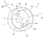
- the bottom plate portion 62 is a flat plate-shaped or thin plate-shaped portion having a thickness direction in the axial direction, and is provided so as to close one end side of the side plate portion 61 in the axial direction. Specifically, the bottom plate portion 62 is seamlessly and integrally connected to the tip portion of the side plate portion 61 in the axial direction. As shown in FIG. 3, the bottom plate portion 62 has an outer edge portion coupled to the side plate portion 61 at a fixed end when the ultrasonic element 5 is attached to the bottom plate portion 62 when transmitting or receiving ultrasonic waves by the ultrasonic element 5. It is configured to ultrasonically vibrate in the axial direction while bending.
- two protrusions 621 are provided on the inner surface of the bottom plate 62, that is, the surface on the side of the internal space 63 in which the ultrasonic element 5 is housed.
- the protrusion 621 is a rod-shaped body that protrudes from the inner surface of the bottom plate portion 62, for example, along the directional central axis DA, and has a cylindrical shape, for example.
- the protrusion 621 is configured to vibrate ultrasonic waves together with the bottom plate portion 62 when the ultrasonic element 5 transmits or receives ultrasonic waves, and serves to generate a plurality of vibration modes.
- two protrusions 621 are formed between the ultrasonic element 5 and the side plate 61 on the inner surface of the bottom plate 62.
- the two protrusions 621 are located at positions separated from the side plate portion 61 and the ultrasonic element 5 and are arranged at positions on both sides of the side plate portion 5 with the ultrasonic element 5 in between. From the viewpoint of controlling the directivity of ultrasonic waves, the two protrusions 621 are preferably arranged symmetrically with respect to the ultrasonic element 5 but are not limited thereto. Further, the two protrusions 621 are arranged at positions where a vibration antinode or a node is formed on the protrusions 621 at the time of the vibration when the bottom plate portion 62 ultrasonically vibrates.
- the two protrusions 621 vibrate like a sound fork when the bottom plate 62 vibrates ultrasonically, and the vibration propagates to the bottom plate 62 to generate the two vibration modes described later. As a result, it plays a role of generating a plurality of resonance frequencies.
- vibration antinode refers to a portion of the bottom plate portion 62 corresponding to the point corresponding to the largest shaking of the standing wave in a state where a standing wave is generated by ultrasonic vibration. .. Further, the “vibration node” refers to a portion of the bottom plate portion 62 corresponding to a point that does not apparently move in the standing wave when the bottom plate portion 62 generates a standing wave due to ultrasonic vibration.
- the protrusion length, width, and the like of the two protrusions 621 are appropriately changed according to the dimensions, materials, and the like of the element housing case 6.
- the protruding length, width, and the like can be calculated by, for example, simulation.
- the above is the basic configuration of the ultrasonic sensor 1 of the present embodiment.
- the ultrasonic element 5 ultrasonically vibrates when an electric signal is input from a wiring (not shown).
- the ultrasonic element 5 ultrasonically vibrates, the element accommodating case 6 is excited by the vibration.
- the ultrasonic microphone 4 composed of the ultrasonic element 5 and the element accommodating case 6 vibrates in a predetermined vibration mode.
- the bottom plate portion 62 is configured such that the ultrasonic element 5 is attached and the two protrusions 621 are symmetrically arranged around the ultrasonic element 5. Then, the two protrusions 621 ultrasonically vibrate together with the bottom plate 62 as the ultrasonic element 5 is driven.
- the ultrasonic microphone 4 As a result of computer simulation of the vibration state of the ultrasonic microphone 4 having the above configuration, the acoustic impedance characteristics shown in FIG. 5 were obtained.
- the ultrasonic microphone 4 two remarkable structural resonance frequencies are generated in the range of 40 to 70 kHz.
- the ultrasonic microphone 4 according to the embodiment has a structure having a structural resonance frequency at about 47 kHz and about 67 kHz. That is, the result shown in FIG. 5 shows that the ultrasonic microphone 4 having a plurality of resonance frequencies can be obtained by providing the protrusion 621 on the bottom plate portion 62.
- the first structure resonance frequency and the second structure resonance frequency are in such a relationship that one does not become the other higher-order resonance frequency.
- the two structural resonance frequencies shown in FIG. 5 are due to the two vibration modes generated in the device housing case 6.
- the first vibration mode is generated by propagating ultrasonic waves from the bottom plate portion 62 to the side plate portion 61.
- the second vibration mode is generated by propagating ultrasonic waves from the bottom plate portion 62 to the protrusion portion 621.
- the structural resonance frequency of about 47 kHz corresponds to the first vibration mode described above.
- the structural resonance frequency of about 67 kHz is presumed to be due to the combination of the vibration wave in the first vibration mode and the vibration wave in the second vibration mode.
- the thickness of the bottom plate portion 62 through which ultrasonic waves propagate becomes thicker (changes) only in the portion where the protrusion 621 is formed, so that the impedance of ultrasonic wave propagation in the bottom plate portion 62 partially increases. Change.
- reflection of ultrasonic vibration occurs at the two protrusions 621 that serve as impedance mismatch points, and thus resonance, that is, a second vibration mode occurs. Then, it is estimated that the second structural resonance frequency is generated by synthesizing the first vibration mode and the second vibration mode in the bottom plate portion 62.
- the ultrasonic microphone 4 having a structural resonance frequency of about 45 kHz is calculated by adding the two protrusions 621. .. Further, in the above simulation result, the diameter d (unit: mm) of the bottom plate portion 62 is such that the two protrusions 621 are arranged symmetrically with the ultrasonic element 5 as the center, and the distance between them is d ⁇ 2/3. It is a case.
- one ultrasonic microphone 4 can have a plurality of structural resonance frequencies by a simple shape change in which a protrusion 621 is provided on the inner surface of the bottom plate portion 62. Further, as compared with the conventional structure in which two bottomed tubular cases of different sizes are bonded together, it is possible to obtain the effect of suppressing a decrease in durability and an increase in cost. Therefore, it becomes one ultrasonic sensor 1 having a configuration having a plurality of resonance frequencies while ensuring durability.
- the element accommodating case 6 may have a side plate portion 61 composed of only a thin-walled portion 611. Even with such a structure, a protrusion 621 is formed on the bottom plate portion 62, which is a propagation path of ultrasonic vibration, and a change point of the vibration impedance is generated, so that the structure has a plurality of resonance frequencies. Is obtained.
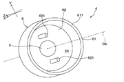
- the shape of the protrusion 621 when it has a rod shape is not limited to a columnar shape, and may be a shape different from the columnar shape.
- the protrusion 621 may have a regular square columnar shape as shown in FIG.
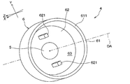
- the protrusion 621 may have a plate shape such as a rectangular square columnar shape as shown in FIG. 8, for example, as well as a rod shape.
- the protrusion 621 may have a shape such as a polygonal pillar or an elliptical pillar, and the shape can be changed as appropriate.
- a change point of vibration impedance is generated in the bottom plate portion 62, and one ultrasonic sensor 1 having a plurality of resonance frequencies is obtained.
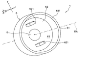
- the ultrasonic sensor 1 may have a structure in which the bottom plate portion 62 has only one protrusion 621.
- the acoustic impedance characteristics shown in FIG. 10 were obtained. Specifically, in this ultrasonic microphone 4, two remarkable structural resonance frequencies of about 47 kHz and about 65 kHz are generated in the range of 40 to 70 kHz. Also in this modified example, since the impedance of the vibration in the bottom plate portion 62 is partially changed by the protrusion portion 621, it becomes one ultrasonic sensor 1 having two resonance frequencies.
- the ultrasonic microphone 4 has a configuration in which the vibration damping portion 64 is attached to the protruding portion 621 of the element accommodating case 6, and is different from the first embodiment. It's different. In this embodiment, the above differences will be mainly described.
- the present invention is not limited to this, and as described in the first embodiment, the protrusions 621
- the number, shape and arrangement can be changed as appropriate.
- the element accommodating case 6 may have a structure having a thin-walled portion 611 and a thick-walled portion 612, as in the first embodiment, and is not limited to the structure of the representative example.
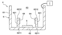
- the vibration damping unit 64 attenuates unintended vibration (hereinafter referred to as “reverberant vibration”) generated in the protrusion 621 due to the ultrasonic wave transmission after transmitting ultrasonic waves to the outside by the ultrasonic element 5, and earlier. It is a member provided so as to be able to receive reflected waves.
- the vibration damping unit 64 is, for example, a known element or electronic component such as a piezo element, a thermistor, or a resistor, and is attached to the protrusion 621 by an adhesive (not shown) or the like, and cancels or absorbs vibration energy due to reverberant vibration. ..
- the vibration damping unit 64 when the vibration damping unit 64 is a piezo element, when reverberation vibration occurs, the vibration damping unit 64 vibrates the protrusion 621 in a direction that cancels the reverberation vibration of the protrusion 621, so to speak, by vibrating in the opposite phase. , Cancels the vibration energy of reverberation vibration.
- the vibration damping unit 64 is connected to the control unit 7 arranged outside the ultrasonic microphone 4 via a wiring (not shown), and is based on the control signal from the control unit 7. It is configured to vibrate.
- the control unit 7 is, for example, an electronic control unit in which a CPU, ROM, RAM, etc. are mounted on a circuit board (not shown), and is referred to as an ECU (abbreviation of Electronic Control Unit).
- the control unit 7 controls the drive of the vibration damping unit 64 according to the state of the ultrasonic microphone 4.
- the control unit 7 causes the protrusion 621 to vibrate in the same direction as the vibration direction of the protrusion 621 due to the ultrasonic wave, that is, the ultrasonic wave. Control is performed to vibrate the vibration damping unit 64 so as not to cancel the above. In other words, when the ultrasonic wave is transmitted to the outside, the control unit 7 vibrates the vibration damping unit 64 in the same direction as the vibration of the protrusion 621, so to speak, controls to vibrate in the same phase.
- the control unit 7 is a vibration damping unit in a direction of canceling the reverberant vibration generated in the protrusion 621. Perform reverse-phase vibration control that vibrates 64.
- the vibration damping unit 64 vibrates the protrusion 621 in the direction opposite to the vibration caused by the reverberation vibration, and plays a role of canceling the energy caused by the reverberation vibration, so that the reverberation vibration is accelerated. Can converge to.
- the maximum displacement amount of the protrusion 621 is when the vibration damping part 64 is not vibrated. It was 38 ⁇ m and 1.68 ⁇ m when vibrated. This indicates that the vibration damping portion 64 vibrates in the opposite phase, so that the vibration displacement of the protrusion 621 is reduced by about 30%, and the reverberation vibration converges earlier.
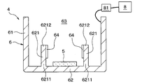
- the vibration damping unit 64 When the vibration damping unit 64 is composed of, for example, a thermista, when reverberation vibration occurs in the protrusion 621, the vibration damping unit 64 absorbs the vibration energy and converts it into electrical energy to reduce the energy of the reverberation vibration. Reverberant vibration is converged at an early stage.
- the vibration damping unit 64 is connected to an external element 8 arranged outside the ultrasonic microphone 4 via a wiring (not shown), and electrical energy generated by energy absorption due to reverberation vibration. Is consumed by the external element 8. Further, in this case, a switch unit 81 for switching the connection state may be arranged between the vibration damping unit 64 and the external element 8.
- the vibration damping unit 64 when the vibration damping unit 64 is composed of a thermistor, when ultrasonic waves are transmitted to the outside, this vibration energy is also converted into electrical energy in the vibration damping unit 64. At this time, if the attenuation of vibration energy is suppressed, the transmission performance of ultrasonic waves may deteriorate. Therefore, the switch unit 81 is in a state where the connection is turned off and the external element 8 is in a state where the converted electric energy is not consumed. To do. As a result, when the ultrasonic waves are transmitted to the outside, the vibration damping by the vibration damping unit 64 is suppressed, and the deterioration of the ultrasonic transmission performance is suppressed.
- the switch unit 81 is in the on state, and the external element 8 is vibration-damped by the reverberant vibration. It is assumed that the electric energy generated in the part 64 is consumed. As a result, after the ultrasonic waves are transmitted to the outside, the reverberation vibration is damped by the vibration damping unit 64, and the reverberation vibration can be converged earlier.
- the external element 8 may be any electronic component that consumes electrical energy, and any electronic component may be used.
- the switch unit 81 is connected to, for example, a control unit (not shown) and is controlled on / off according to the driving state of the ultrasonic microphone 4, but it may be any one that can be switched on / off. , Known elements, electronic parts and the like can be used.
- the vibration damping portion 64 is arranged at an arbitrary position between the root portion 6211 and the tip portion 6212 on the bottom plate portion 62 side of the protrusion 621, for example. From the viewpoint of reducing reverberation vibration, the vibration damping portion 64 is attached to a predetermined region of the protrusion 621 including at least a portion having the largest displacement due to reverberation vibration.
- the protrusion 621 when the protrusion 621 has a plate shape having a constant thickness as shown in FIG. 11, for example, the protrusion 621 is a portion where the tip portion 6212 is most displaced during reverberation vibration.
- the vibration damping portion 64 is attached to a predetermined region of the protrusion 621 including at least the tip portion 6212. This can be done even in the case where the vibration displacement at the tip portion 6212 is the largest by making the protrusion 621 have another arbitrary shape such that the thickness becomes thinner from the root portion 6211 toward the tip portion 6212. The same is true.
- the protrusion 621 has a shape having a constriction 6213 having the smallest thickness on the way from the root portion 6211 to the tip portion 6212 as shown in FIG. 15, the protrusion 621 has a constriction 6213.
- the vibration displacement becomes the largest during reverberation vibration.
- the vibration damping portion 64 is attached to a predetermined region of the protrusion 621 including at least the constricted portion 6213.
- the vibration damping portion 64 is preferably arranged at a portion in consideration of the vibration displacement of the protrusion 621 during reverberation vibration.
- the vibration displacement of the protrusion 621 during reverberant vibration is calculated by an arbitrary simulation program such as ultrasonic analysis software. Further, when a plurality of protrusions 621 are formed, the vibration damping portion 64 may be attached to all the protrusions 621 or only to a part of the protrusions 621, and may be attached to only some of the protrusions 621. The object to be attached is appropriately determined according to the vibration displacement of.
- the reverberation vibration generated in the protrusion 621 is reduced by the vibration damping portion 64, and the effect of being able to receive the reflected wave earlier can be obtained.
- the ultrasonic sensor of the present embodiment is expected to improve the detection limit distance particularly at a short distance.
- FIG. 16 is a cross-sectional view corresponding to FIG.
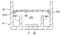
- the ultrasonic sensor of the present embodiment is different from the first embodiment in that it has a protective material 65 that closes an opening on the opposite side of the element housing case 6 from the bottom plate portion 62. To do. In this embodiment, this difference will be mainly described.
- the protective material 65 closes the other end side of the side plate portion 61 opposite to the side closed by the bottom plate portion 62, and connects a circuit (not shown) connected to the ultrasonic element 5 from the outside air. It is a member to protect, and is made of, for example, a silicone resin. Further, the protective material 65 is arranged at a distance from the protrusion 621 so as not to come into contact with the protrusion 621 so as not to hinder the vibration of the protrusion 621 when the reflected wave is received. As a result, in the present embodiment, the ultrasonic microphone 4 is formed with a closed space 631 in which the circuit (not shown) in the element accommodating case 6 is not exposed to the moisture of the outside air or the like. This is to achieve both circuit protection in the ultrasonic microphone 4 and maintenance of vibration characteristics by the protrusion 621.
- the protective material 65 is an ultrasonic sensor arranged so as to fill the internal space 63 of the element accommodating case 6 will be examined. Even in this case, since the internal space 63 of the element accommodating case 6 is covered with the protective material 65, a circuit (not shown) can be protected from the outside air.
- the protrusion 621 since the protrusion 621 is in contact with the protective material 65, the vibration of the protrusion 621 when receiving the reflected wave of the ultrasonic wave transmitted to the outside is suppressed, and the vibration of the protrusion 621 is suppressed.
- the properties can be reduced.
- the protective material 65 is arranged with a circuit (not shown) connected to the ultrasonic element 5 by closing the end portion of the side plate portion 61 opposite to the bottom plate portion 62. It forms a closed space 631 and is arranged at a distance from the protrusion 621.
- a circuit (not shown) is protected from the outside air and does not come into contact with the protrusion 621, so that the vibration of the protrusion 621 when the reflected wave of ultrasonic waves is received from the outside is not hindered and the vibration characteristics are maintained. It becomes possible.
- the opening of the ultrasonic element 5 and the element accommodating case 6 having a circuit (not shown) is arranged in the vertical direction, and an amount of silicone resin that does not fill the internal space 63 is injected from below. It can be formed by a process such as closing the opening and hardening the opening.
- an ultrasonic wave having an effect of both protecting the circuit in the ultrasonic microphone 4 and not suppressing unnecessary vibration of the protrusion 621 can be obtained. It becomes a sensor.
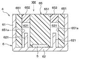
- FIG. 19 the outer shapes of the ultrasonic element 5 and the protrusion 621, which are covered with the protective material 65 and cannot be seen from the top view, are shown by broken lines in order to make the arrangement of the constituent members easy to understand.
- the protective material 65 has a base portion 651 having the same number of through holes 651a as the protrusions 621 and an end portion of the through holes 651a of the base portion 651 opposite to the bottom plate portion 62. It is composed of a closing member 652 that closes the side.
- the base portion 651 is formed with a through hole 651a in which the protrusion 621 is housed, and fills an area of the internal space 63 of the element housing case 6 excluding the protrusion 621 and its periphery.
- the through hole 651a may have a cylindrical shape according to the outer shape of the protrusion 621, but the shape may be such that the protrusion 621 and the base portion 651 do not abut. Not limited to the example.
- the protrusion 621 is arranged near the center of the through hole 651a, and the base portion 651 is in a state of not abutting with the protrusion 621.
- a closing member 652 is arranged on the end side of the through hole 651a opposite to the protrusion 621.
- the closing member 652 is a member for closing the end portion of the through hole 651a and forming a closing space 631 in which the protrusion 621 is accommodated.
- the closing member 652 may be made of the same silicone resin material as the base portion 651, or may be made of a material different from the base portion 651, as long as the end portion of the through hole 651a can be closed.
- the protective material 65 is formed, for example, through the steps shown in FIGS. 20A to 20C.
- the tubular member 100 surrounding the protrusion 621 is attached to the element accommodating case 6 including the protrusion 621 and the ultrasonic element 5.
- the base portion 651 is formed by pouring a silicone resin material into the outside of the tubular member 100 and curing it.
- FIG. 20C by pulling out the tubular member 100, a through hole 651a in which the protrusion 621 is housed is formed.
- the element accommodating case 6 is arranged so that the opening of the through hole 651a faces in the vertical direction, and a predetermined amount of silicone resin material is injected from below to fill a part of the through hole 651a and cured.
- a predetermined amount of silicone resin material is injected from below to fill a part of the through hole 651a and cured.
- the modified example also provides an ultrasonic sensor having the same effect as that of the third embodiment.
- the ultrasonic sensor of the present embodiment is different from the third embodiment in that, in addition to the protective material 65, a foam member 66 having a recess 661 is arranged between the protective material 65 and the protrusion 621. In this embodiment, this difference will be mainly described.
- the foamed member 66 includes a recess 661 formed so as to cover the protrusion 621, and is composed of, for example, a foamed elastic body such as foamed silicone having insulating properties and elasticity.
- the foam member 66 has a height smaller than that of the side plate portion 61, and has the same outer diameter as the inner diameter of the side plate portion 61 so that the material of the protective material 65 to be formed later does not flow into the protrusion 621.
- the foaming member 66 is a member that serves as a base for forming the protective material 65 while protecting the protrusion 621.
- the foam member 66 also plays a role of suppressing vibration transmission from the ultrasonic microphone 4 to the sensor case 2 (not shown in FIG. 21).
- the recess 661 is at least larger than the outer shape of the protrusion 621, and has an arbitrary shape so that the protrusion 621 and the foam member 66 do not come into contact with each other.
- the recess 661 is a member that is arranged so as to cover the protrusion 621 and forms a closed space 631 in which the protrusion 621 is housed.
- the recess 661 is formed by any method such as cutting.
- the foam member 66 in which the recess 661 is formed is fitted into the element accommodating case 6 so as to cover the protrusion 621 with the recess 661, and then a silicone resin material is placed on the foam member 66. Obtained by pouring and curing.
- the process of forming the protective material 65 is simplified, so that the effect of reducing the manufacturing cost is also expected.
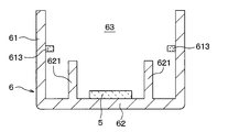
- the foam member 66 is a plate-shaped member having no recess, and is formed on a convex portion 613 which is formed at a position higher than the tip of the protrusion 621 from the bottom plate portion 62 of the side plate portion 61. May be placed in.
- the foam member 66 has the same outer diameter as the inner diameter of the side plate portion 61, is arranged in contact with the convex portion 613, and closes a predetermined region including the protrusion 621 to form a closed space 631.
- the convex portion 613 is formed of any material such as a silicone resin material. As shown in FIG. 23A, for example, the convex portion 613 can be formed by applying an adhesive (not shown) to a portion of the inner wall of the side plate portion 61 higher than the tip of the protrusion 621 and then attaching the convex portion 613.
- the convex portion 613 may be in the shape of a ring continuously formed on the entire circumference of the inner wall of the side plate portion 61, or may be formed intermittently, as long as the foaming member 66 can be prevented from falling to the bottom plate portion 62. You may. Further, the shape, size, and dimensions of the convex portion 613 can be changed as appropriate.
- the foam member 66 is arranged on the convex portion 613 after the convex portion 613 is formed, for example, as shown in FIG. 23B.
- a closed space 631 in which the protrusion 621 is housed is formed, and the foaming member 66 supported by the protrusion 613 does not come into contact with the protrusion 621, which protects a circuit (not shown) and protects the protrusion 621.
- the structure is compatible with maintaining vibration characteristics.
- the modified example also provides an ultrasonic sensor that can obtain the same effect as that of the fourth embodiment.
- the housing 9 is attached to the outer wall surface of the side plate portion 61 of the element housing case 6 via an adhesive and a waterproof member 10 (not shown), and the internal space 63 is the internal space 91 of the housing 9. At the same time, it differs from the first embodiment in that it is closed by the housing 9.
- the housing 9 is made of, for example, an arbitrary metal material, and is attached to the outer wall surface on the outer peripheral side of the side plate portion 61 via an adhesive and a waterproof member 10 (not shown). That is, the housing 9 is a member that forms a closed space for circuit protection by arranging the housing 9 outside the element accommodating case 6 and covering a circuit (not shown) connected to the ultrasonic element 5 so as not to be exposed to the outside air. Is.
- other members such as a circuit board (not shown) may be arranged in the internal space 91 of the housing 9, but in this case, the other members are arranged so as not to come into contact with at least the protrusion 621. ..
- the waterproof member 10 is made of any resin material such as waterproof rubber.
- the waterproof member 10 is a member that prevents moisture in the air from entering the housing 9 from the outside, is attached to the housing 9 by any method, and is attached to the element housing case 6 by an adhesive (not shown) or the like. It is attached.
- the ultrasonic sensor of the present embodiment has a configuration in which a circuit (not shown) in the element accommodating case 6 is protected from the outside air and other members do not come into contact with the protrusion 621. Both circuit protection and maintenance of vibration characteristics are compatible.
- the ultrasonic sensor in addition to the effect of the first embodiment, can obtain the effect of achieving both circuit protection and maintenance of vibration characteristics as in the third embodiment.
- the ultrasonic sensor 1 is not limited to a configuration capable of transmitting and receiving ultrasonic waves, and may have a configuration capable of only transmitting ultrasonic waves.
- the ultrasonic sensor 1 may be configured to have only a function of receiving the reflected wave of the exploration wave, which is an ultrasonic wave transmitted from another ultrasonic transmitter, by an object existing in the surroundings. That is, the ultrasonic microphone 4 may be for transmission / reception, transmission, or reception.
- the outer shape of the ultrasonic microphone 4, that is, the element housing case 6 is not limited to a substantially cylindrical shape, and may be a substantially regular hexagonal columnar shape, a substantially regular octagonal columnar shape, or the like.
- the ultrasonic element 5 is not limited to the piezoelectric element, and for example, a so-called capacitance type element may be used.
- the plurality of components that are seamlessly and integrally formed with each other may be formed by laminating separate members from each other.
- a plurality of components formed by laminating separate members may be seamlessly and integrally formed with each other.
- the element accommodating case 6 may have a configuration in which a plurality of separate members are joined by welding or adhesion.
- the plurality of components formed of the same material may be formed of different materials.
- a plurality of components that were formed of different materials may be formed of the same material.
- the protrusion 621 is not only integrally made of the same material as the element accommodating case 6, but may be made of a material different from that of the element accommodating case 6.
- the protrusion 621 is formed separately from the other parts of the element accommodating case 6, and may be attached with an arbitrary adhesive, or may be integrated with the bottom plate portion 62 by welding or the like.
- the vibration propagation of the ultrasonic microphone 4 can be controlled by forming the protrusion 621 with a material different from the bottom plate portion 62, that is, a material having a different propagation speed of ultrasonic vibration.
- the number of protrusions 621 is not limited to the number in the example of the above embodiment, and three or more protrusions 621 may be provided on the bottom plate 62.
- the shape of the protrusion 621 is not limited to a simple columnar shape or a plate shape, but may be a pyramid shape such as a conical shape, or a notch or the like may be formed. It may have other different shapes. By changing the shape of the protrusion 621, the balance between the weight and the thickness of the bottom plate 62 can be adjusted, and the frequency and magnitude of the resonance vibration can be changed.
Landscapes
- Engineering & Computer Science (AREA)
- Radar, Positioning & Navigation (AREA)
- Remote Sensing (AREA)
- Physics & Mathematics (AREA)
- Computer Networks & Wireless Communication (AREA)
- General Physics & Mathematics (AREA)
- Acoustics & Sound (AREA)
- Transducers For Ultrasonic Waves (AREA)
- Measurement Of Velocity Or Position Using Acoustic Or Ultrasonic Waves (AREA)
Priority Applications (3)
| Application Number | Priority Date | Filing Date | Title |
|---|---|---|---|
| CN202080033612.4A CN113785221B (zh) | 2019-05-06 | 2020-04-24 | 超声波传感器 |
| DE112020002262.5T DE112020002262T5 (de) | 2019-05-06 | 2020-04-24 | Ultraschallsensor |
| US17/519,326 US11971479B2 (en) | 2019-05-06 | 2021-11-04 | Ultrasonic sensor |
Applications Claiming Priority (4)
| Application Number | Priority Date | Filing Date | Title |
|---|---|---|---|
| JP2019-087230 | 2019-05-06 | ||
| JP2019087230 | 2019-05-06 | ||
| JP2020074424A JP7371564B2 (ja) | 2019-05-06 | 2020-04-17 | 超音波センサ |
| JP2020-074424 | 2020-04-17 |
Related Child Applications (1)
| Application Number | Title | Priority Date | Filing Date |
|---|---|---|---|
| US17/519,326 Continuation US11971479B2 (en) | 2019-05-06 | 2021-11-04 | Ultrasonic sensor |
Publications (1)
| Publication Number | Publication Date |
|---|---|
| WO2020226081A1 true WO2020226081A1 (ja) | 2020-11-12 |
Family
ID=73045227
Family Applications (1)
| Application Number | Title | Priority Date | Filing Date |
|---|---|---|---|
| PCT/JP2020/017818 Ceased WO2020226081A1 (ja) | 2019-05-06 | 2020-04-24 | 超音波センサ |
Country Status (5)
| Country | Link |
|---|---|
| US (1) | US11971479B2 (https=) |
| JP (1) | JP7371564B2 (https=) |
| CN (1) | CN113785221B (https=) |
| DE (1) | DE112020002262T5 (https=) |
| WO (1) | WO2020226081A1 (https=) |
Families Citing this family (4)
| Publication number | Priority date | Publication date | Assignee | Title |
|---|---|---|---|---|
| DE112022001312T5 (de) * | 2021-03-02 | 2023-12-21 | Murata Manufacturing Co., Ltd. | Ultraschallsensor |
| JP7730696B2 (ja) * | 2021-08-30 | 2025-08-28 | 本田技研工業株式会社 | 超音波センサの取付け構造 |
| JP7800507B2 (ja) * | 2023-06-12 | 2026-01-16 | 株式会社Soken | 車載センサ装置 |
| JP2025029403A (ja) * | 2023-08-21 | 2025-03-06 | パナソニックオートモーティブシステムズ株式会社 | トランスデューサ装置および外装品 |
Citations (5)
| Publication number | Priority date | Publication date | Assignee | Title |
|---|---|---|---|---|
| JPH02288500A (ja) * | 1989-04-28 | 1990-11-28 | Toshiba Corp | 超音波トランスジユーサ |
| JPH11237468A (ja) * | 1998-02-24 | 1999-08-31 | Matsushita Electric Works Ltd | 超音波送受波器及びその製造方法 |
| JP2001016694A (ja) * | 1999-06-25 | 2001-01-19 | Denso Corp | 超音波センサ |
| US20110018367A1 (en) * | 2009-07-22 | 2011-01-27 | Yong Jin Kim | Horizontal linear vibrator |
| WO2016147917A1 (ja) * | 2015-03-16 | 2016-09-22 | 株式会社村田製作所 | 超音波センサ |
Family Cites Families (14)
| Publication number | Priority date | Publication date | Assignee | Title |
|---|---|---|---|---|
| JPH11155291A (ja) * | 1997-11-25 | 1999-06-08 | Matsushita Electric Ind Co Ltd | 超音波モータ及び圧電バイブレータ |
| KR100510071B1 (ko) * | 2003-03-31 | 2005-08-25 | 삼성전자주식회사 | 압전 진동체를 이용한 전자음향장치 |
| JP4127810B2 (ja) * | 2003-09-19 | 2008-07-30 | オリンパス株式会社 | 超音波振動子およびその製造方法 |
| JP2007147319A (ja) * | 2005-11-24 | 2007-06-14 | Nippon Soken Inc | 障害物検知装置 |
| JP4901537B2 (ja) * | 2006-08-25 | 2012-03-21 | 公益財団法人鉄道総合技術研究所 | 騒音振動低減装置 |
| JP2010278594A (ja) | 2009-05-27 | 2010-12-09 | Nippon Ceramic Co Ltd | 超音波送受波器 |
| JP2010278913A (ja) | 2009-05-29 | 2010-12-09 | Nippon Ceramic Co Ltd | 超音波送受波器 |
| KR20130034877A (ko) * | 2011-09-29 | 2013-04-08 | 삼성전기주식회사 | 초음파 센서 및 그 제조방법 |
| WO2013100142A1 (ja) * | 2011-12-28 | 2013-07-04 | パナソニック株式会社 | 超音波センサ |
| DE102013214661B4 (de) | 2012-08-03 | 2023-01-05 | Semiconductor Energy Laboratory Co., Ltd. | Licht emittierendes Element, Licht emittierende Vorrichtung und Beleuchtungsvorrichtung |
| JP6245496B2 (ja) * | 2013-05-23 | 2017-12-13 | パナソニックIpマネジメント株式会社 | 超音波センサ装置及びその取付方法 |
| DE102015107899A1 (de) * | 2015-05-20 | 2016-11-24 | Valeo Schalter Und Sensoren Gmbh | Ultraschallsensor für ein Kraftfahrzeug, Kraftfahrzeug sowie Verfahren zum Herstellen eines Ultraschallsensors |
| WO2018164153A1 (ja) * | 2017-03-07 | 2018-09-13 | 株式会社デンソー | 超音波センサ |
| CN109744999A (zh) | 2017-11-03 | 2019-05-14 | 光宝电子(广州)有限公司 | 穿戴式系统、穿戴式装置及其云端伺服器与操作方法 |
-
2020
- 2020-04-17 JP JP2020074424A patent/JP7371564B2/ja active Active
- 2020-04-24 CN CN202080033612.4A patent/CN113785221B/zh active Active
- 2020-04-24 WO PCT/JP2020/017818 patent/WO2020226081A1/ja not_active Ceased
- 2020-04-24 DE DE112020002262.5T patent/DE112020002262T5/de active Pending
-
2021
- 2021-11-04 US US17/519,326 patent/US11971479B2/en active Active
Patent Citations (5)
| Publication number | Priority date | Publication date | Assignee | Title |
|---|---|---|---|---|
| JPH02288500A (ja) * | 1989-04-28 | 1990-11-28 | Toshiba Corp | 超音波トランスジユーサ |
| JPH11237468A (ja) * | 1998-02-24 | 1999-08-31 | Matsushita Electric Works Ltd | 超音波送受波器及びその製造方法 |
| JP2001016694A (ja) * | 1999-06-25 | 2001-01-19 | Denso Corp | 超音波センサ |
| US20110018367A1 (en) * | 2009-07-22 | 2011-01-27 | Yong Jin Kim | Horizontal linear vibrator |
| WO2016147917A1 (ja) * | 2015-03-16 | 2016-09-22 | 株式会社村田製作所 | 超音波センサ |
Also Published As
| Publication number | Publication date |
|---|---|
| JP7371564B2 (ja) | 2023-10-31 |
| JP2020184753A (ja) | 2020-11-12 |
| CN113785221A (zh) | 2021-12-10 |
| US11971479B2 (en) | 2024-04-30 |
| CN113785221B (zh) | 2024-07-09 |
| DE112020002262T5 (de) | 2022-01-27 |
| US20220057507A1 (en) | 2022-02-24 |
Similar Documents
| Publication | Publication Date | Title |
|---|---|---|
| US11971479B2 (en) | Ultrasonic sensor | |
| JP7211220B2 (ja) | 超音波センサ | |
| JP5522100B2 (ja) | 超音波センサ | |
| EP1962552B1 (en) | Ultrasonic transducer | |
| CN101529927B (zh) | 超声波传感器 | |
| JP5522311B2 (ja) | 超音波センサおよびその製造方法 | |
| CN102726064B (zh) | 超声波振动装置 | |
| US12481058B2 (en) | Ultrasonic sensor | |
| JP2007142967A (ja) | 超音波センサ | |
| US12123987B2 (en) | Ultrasonic sensor | |
| JP7167567B2 (ja) | 超音波センサ | |
| JP2019140672A (ja) | 超音波センサ | |
| CN110709175A (zh) | 超声传感器 | |
| JP2021016036A (ja) | 超音波センサ | |
| WO2014132492A1 (ja) | 超音波センサ | |
| JP2008271439A (ja) | 超音波センサ | |
| JP7435282B2 (ja) | 超音波トランスデューサ | |
| WO2021172094A1 (ja) | 超音波トランスデューサ | |
| JP2021183951A (ja) | 超音波センサ取付構造 |
Legal Events
| Date | Code | Title | Description |
|---|---|---|---|
| 121 | Ep: the epo has been informed by wipo that ep was designated in this application |
Ref document number: 20802021 Country of ref document: EP Kind code of ref document: A1 |
|
| 122 | Ep: pct application non-entry in european phase |
Ref document number: 20802021 Country of ref document: EP Kind code of ref document: A1 |