WO2020217984A1 - 電力変換装置 - Google Patents
電力変換装置 Download PDFInfo
- Publication number
- WO2020217984A1 WO2020217984A1 PCT/JP2020/015764 JP2020015764W WO2020217984A1 WO 2020217984 A1 WO2020217984 A1 WO 2020217984A1 JP 2020015764 W JP2020015764 W JP 2020015764W WO 2020217984 A1 WO2020217984 A1 WO 2020217984A1
- Authority
- WO
- WIPO (PCT)
- Prior art keywords
- pipe
- connector
- flange portion
- power conversion
- conversion device
- Prior art date
- Legal status (The legal status is an assumption and is not a legal conclusion. Google has not performed a legal analysis and makes no representation as to the accuracy of the status listed.)
- Ceased
Links
Images


Classifications
-
- H—ELECTRICITY
- H01—ELECTRIC ELEMENTS
- H01L—SEMICONDUCTOR DEVICES NOT COVERED BY CLASS H10
- H01L23/00—Details of semiconductor or other solid state devices
- H01L23/34—Arrangements for cooling, heating, ventilating or temperature compensation ; Temperature sensing arrangements
- H01L23/40—Mountings or securing means for detachable cooling or heating arrangements ; fixed by friction, plugs or springs
- H01L23/4006—Mountings or securing means for detachable cooling or heating arrangements ; fixed by friction, plugs or springs with bolts or screws
- H01L23/4012—Mountings or securing means for detachable cooling or heating arrangements ; fixed by friction, plugs or springs with bolts or screws for stacked arrangements of a plurality of semiconductor devices
-
- H—ELECTRICITY
- H01—ELECTRIC ELEMENTS
- H01L—SEMICONDUCTOR DEVICES NOT COVERED BY CLASS H10
- H01L23/00—Details of semiconductor or other solid state devices
- H01L23/34—Arrangements for cooling, heating, ventilating or temperature compensation ; Temperature sensing arrangements
- H01L23/40—Mountings or securing means for detachable cooling or heating arrangements ; fixed by friction, plugs or springs
-
- H—ELECTRICITY
- H01—ELECTRIC ELEMENTS
- H01L—SEMICONDUCTOR DEVICES NOT COVERED BY CLASS H10
- H01L23/00—Details of semiconductor or other solid state devices
- H01L23/34—Arrangements for cooling, heating, ventilating or temperature compensation ; Temperature sensing arrangements
- H01L23/46—Arrangements for cooling, heating, ventilating or temperature compensation ; Temperature sensing arrangements involving the transfer of heat by flowing fluids
- H01L23/473—Arrangements for cooling, heating, ventilating or temperature compensation ; Temperature sensing arrangements involving the transfer of heat by flowing fluids by flowing liquids
-
- H—ELECTRICITY
- H02—GENERATION; CONVERSION OR DISTRIBUTION OF ELECTRIC POWER
- H02M—APPARATUS FOR CONVERSION BETWEEN AC AND AC, BETWEEN AC AND DC, OR BETWEEN DC AND DC, AND FOR USE WITH MAINS OR SIMILAR POWER SUPPLY SYSTEMS; CONVERSION OF DC OR AC INPUT POWER INTO SURGE OUTPUT POWER; CONTROL OR REGULATION THEREOF
- H02M7/00—Conversion of AC power input into DC power output; Conversion of DC power input into AC power output
- H02M7/42—Conversion of DC power input into AC power output without possibility of reversal
- H02M7/44—Conversion of DC power input into AC power output without possibility of reversal by static converters
- H02M7/48—Conversion of DC power input into AC power output without possibility of reversal by static converters using discharge tubes with control electrode or semiconductor devices with control electrode
- H02M7/53—Conversion of DC power input into AC power output without possibility of reversal by static converters using discharge tubes with control electrode or semiconductor devices with control electrode using devices of a triode or transistor type requiring continuous application of a control signal
- H02M7/537—Conversion of DC power input into AC power output without possibility of reversal by static converters using discharge tubes with control electrode or semiconductor devices with control electrode using devices of a triode or transistor type requiring continuous application of a control signal using semiconductor devices only, e.g. single switched pulse inverters
-
- H—ELECTRICITY
- H05—ELECTRIC TECHNIQUES NOT OTHERWISE PROVIDED FOR
- H05K—PRINTED CIRCUITS; CASINGS OR CONSTRUCTIONAL DETAILS OF ELECTRIC APPARATUS; MANUFACTURE OF ASSEMBLAGES OF ELECTRICAL COMPONENTS
- H05K7/00—Constructional details common to different types of electric apparatus
- H05K7/20—Modifications to facilitate cooling, ventilating, or heating
- H05K7/2089—Modifications to facilitate cooling, ventilating, or heating for power electronics, e.g. for inverters for controlling motor
- H05K7/20927—Liquid coolant without phase change
-
- H—ELECTRICITY
- H02—GENERATION; CONVERSION OR DISTRIBUTION OF ELECTRIC POWER
- H02M—APPARATUS FOR CONVERSION BETWEEN AC AND AC, BETWEEN AC AND DC, OR BETWEEN DC AND DC, AND FOR USE WITH MAINS OR SIMILAR POWER SUPPLY SYSTEMS; CONVERSION OF DC OR AC INPUT POWER INTO SURGE OUTPUT POWER; CONTROL OR REGULATION THEREOF
- H02M1/00—Details of apparatus for conversion
- H02M1/0067—Converter structures employing plural converter units, other than for parallel operation of the units on a single load
- H02M1/007—Plural converter units in cascade
-
- H—ELECTRICITY
- H02—GENERATION; CONVERSION OR DISTRIBUTION OF ELECTRIC POWER
- H02M—APPARATUS FOR CONVERSION BETWEEN AC AND AC, BETWEEN AC AND DC, OR BETWEEN DC AND DC, AND FOR USE WITH MAINS OR SIMILAR POWER SUPPLY SYSTEMS; CONVERSION OF DC OR AC INPUT POWER INTO SURGE OUTPUT POWER; CONTROL OR REGULATION THEREOF
- H02M1/00—Details of apparatus for conversion
- H02M1/0067—Converter structures employing plural converter units, other than for parallel operation of the units on a single load
- H02M1/008—Plural converter units for generating at two or more independent and non-parallel outputs, e.g. systems with plural point of load switching regulators
-
- H—ELECTRICITY
- H02—GENERATION; CONVERSION OR DISTRIBUTION OF ELECTRIC POWER
- H02M—APPARATUS FOR CONVERSION BETWEEN AC AND AC, BETWEEN AC AND DC, OR BETWEEN DC AND DC, AND FOR USE WITH MAINS OR SIMILAR POWER SUPPLY SYSTEMS; CONVERSION OF DC OR AC INPUT POWER INTO SURGE OUTPUT POWER; CONTROL OR REGULATION THEREOF
- H02M1/00—Details of apparatus for conversion
- H02M1/08—Circuits specially adapted for the generation of control voltages for semiconductor devices incorporated in static converters
- H02M1/088—Circuits specially adapted for the generation of control voltages for semiconductor devices incorporated in static converters for the simultaneous control of series or parallel connected semiconductor devices
-
- H—ELECTRICITY
- H02—GENERATION; CONVERSION OR DISTRIBUTION OF ELECTRIC POWER
- H02M—APPARATUS FOR CONVERSION BETWEEN AC AND AC, BETWEEN AC AND DC, OR BETWEEN DC AND DC, AND FOR USE WITH MAINS OR SIMILAR POWER SUPPLY SYSTEMS; CONVERSION OF DC OR AC INPUT POWER INTO SURGE OUTPUT POWER; CONTROL OR REGULATION THEREOF
- H02M3/00—Conversion of DC power input into DC power output
- H02M3/02—Conversion of DC power input into DC power output without intermediate conversion into AC
- H02M3/04—Conversion of DC power input into DC power output without intermediate conversion into AC by static converters
- H02M3/10—Conversion of DC power input into DC power output without intermediate conversion into AC by static converters using discharge tubes with control electrode or semiconductor devices with control electrode
- H02M3/145—Conversion of DC power input into DC power output without intermediate conversion into AC by static converters using discharge tubes with control electrode or semiconductor devices with control electrode using devices of a triode or transistor type requiring continuous application of a control signal
- H02M3/155—Conversion of DC power input into DC power output without intermediate conversion into AC by static converters using discharge tubes with control electrode or semiconductor devices with control electrode using devices of a triode or transistor type requiring continuous application of a control signal using semiconductor devices only
- H02M3/156—Conversion of DC power input into DC power output without intermediate conversion into AC by static converters using discharge tubes with control electrode or semiconductor devices with control electrode using devices of a triode or transistor type requiring continuous application of a control signal using semiconductor devices only with automatic control of output voltage or current, e.g. switching regulators
- H02M3/158—Conversion of DC power input into DC power output without intermediate conversion into AC by static converters using discharge tubes with control electrode or semiconductor devices with control electrode using devices of a triode or transistor type requiring continuous application of a control signal using semiconductor devices only with automatic control of output voltage or current, e.g. switching regulators including plural semiconductor devices as final control devices for a single load
-
- H—ELECTRICITY
- H02—GENERATION; CONVERSION OR DISTRIBUTION OF ELECTRIC POWER
- H02M—APPARATUS FOR CONVERSION BETWEEN AC AND AC, BETWEEN AC AND DC, OR BETWEEN DC AND DC, AND FOR USE WITH MAINS OR SIMILAR POWER SUPPLY SYSTEMS; CONVERSION OF DC OR AC INPUT POWER INTO SURGE OUTPUT POWER; CONTROL OR REGULATION THEREOF
- H02M7/00—Conversion of AC power input into DC power output; Conversion of DC power input into AC power output
- H02M7/42—Conversion of DC power input into AC power output without possibility of reversal
- H02M7/44—Conversion of DC power input into AC power output without possibility of reversal by static converters
- H02M7/48—Conversion of DC power input into AC power output without possibility of reversal by static converters using discharge tubes with control electrode or semiconductor devices with control electrode
- H02M7/53—Conversion of DC power input into AC power output without possibility of reversal by static converters using discharge tubes with control electrode or semiconductor devices with control electrode using devices of a triode or transistor type requiring continuous application of a control signal
- H02M7/537—Conversion of DC power input into AC power output without possibility of reversal by static converters using discharge tubes with control electrode or semiconductor devices with control electrode using devices of a triode or transistor type requiring continuous application of a control signal using semiconductor devices only, e.g. single switched pulse inverters
- H02M7/5387—Conversion of DC power input into AC power output without possibility of reversal by static converters using discharge tubes with control electrode or semiconductor devices with control electrode using devices of a triode or transistor type requiring continuous application of a control signal using semiconductor devices only, e.g. single switched pulse inverters in a bridge configuration
Definitions
- This disclosure relates to a power converter.
- Patent Document 1 describes a semiconductor module having a built-in switching element, a cooler for cooling the semiconductor module, a case for accommodating the semiconductor module and the cooler, a refrigerant introduction pipe which is a refrigerant flow pipe of the cooler, and a refrigerant introduction pipe.
- a power conversion device including a connector provided for each of the refrigerant discharge pipes is disclosed.
- the connector is interposed between the refrigerant flow pipe of the cooler and the external pipe.
- This connector has a tubular portion that communicates with a refrigerant flow pipe and a flange portion that protrudes outward in the radial direction from the tubular portion, and is configured as an integral part made of a resin material.
- the connector is an integral part, it is necessary to prepare a type of connector according to the assumed shape of the external pipe in order to increase the versatility for connection with various shapes of external pipe. In this case, since the shape of the connector is changed over the entire connector, there may be a problem that the cost required for manufacturing the connector is high.
- the present disclosure is intended to provide a power conversion device capable of increasing versatility at low cost for a connector interposed between a refrigerant flow pipe of a cooler for a semiconductor module and an external pipe.
- a semiconductor module with a built-in switching element and A cooler having a heat exchange unit capable of exchanging heat with the semiconductor module, an introduction pipe for introducing a refrigerant into the heat exchange unit, and an discharge pipe for discharging the refrigerant from the heat exchange unit.
- a case for accommodating the semiconductor module and the cooler A connector connected to the refrigerant flow pipe, which is at least one of the introduction pipe and the discharge pipe of the cooler, outside the case.
- a sealing member that seals between the refrigerant flow pipe and the connector With The connector has a pipe portion communicating with the refrigerant flow pipe and a flange portion fixed to the case, and the pipe portion and the pipe portion are inserted in a state where the pipe portion is inserted into the insertion hole of the flange portion. Power converters, whose flanges are joined to each other It is in.
- the heat exchange unit of the cooler can exchange heat with a semiconductor module having a built-in switching element.
- the connector is connected to the refrigerant flow pipe, which is at least one of the inlet pipe and the discharge pipe of the cooler, outside the case. This connector is interposed between the refrigerant flow pipe of the cooler and the external pipe. When the connector is connected to the refrigerant flow pipe, the space between the refrigerant flow pipe and the connector is sealed via the sealing member.
- the connector is configured so that the pipe portion and the flange portion are joined to each other in a state where the pipe portion, which is a member different from the flange portion, is inserted into the insertion hole of the flange portion. For this reason, while sharing the flange portion for external pipes of different shapes, by changing only the shape of the pipe portion, which is a separate member from the flange portion, it is possible to connect to external pipes of various shapes. You can improve your sex. At this time, since it can be dealt with only by changing the shape of the pipe portion, it is not necessary to increase the number of dies for forming the flange portion, for example, and the cost required for manufacturing the connector can be kept low.
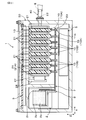
- FIG. 1 is a cross-sectional view of the power conversion device of the first embodiment.
- FIG. 2 is a cross-sectional view taken along the line II-II of FIG.
- FIG. 3 is a front view of the semiconductor module in FIG.
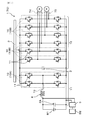
- FIG. 4 is an inverter circuit diagram of the power conversion device of the first embodiment.
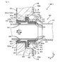
- FIG. 5 is a cross-sectional view of the first region in FIG.
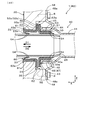
- FIG. 6 is a cross-sectional view of the second region in FIG.
- FIG. 7 is a diagram schematically showing a state when the connector and the sealing member are assembled.
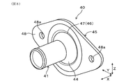
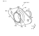
- FIG. 8 is a perspective view of the connector of the power conversion device of the first embodiment as viewed from the pipe portion side.
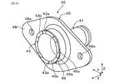
- FIG. 9 is a perspective view of the connector of FIG. 8 as viewed from the back surface side of the flange portion.
- FIG. 10 is a flowchart showing a caulking operation for the connector of FIG.
- FIG. 11 is a perspective view showing a state in which the pipe portion and the flange portion are temporarily assembled in the first step in FIG.
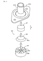
- FIG. 12 is a perspective view of the caulking jig used in the joining operation of FIG.
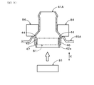
- FIG. 13 is a diagram schematically showing the state of the second step in FIG.
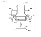
- FIG. 14 is a diagram schematically showing the state of the third step in FIG.
- FIG. 15 is a diagram schematically showing the state of the fourth step in FIG.
- FIG. 16 is a perspective view of the connector of the power conversion device of the second embodiment corresponding to FIG.
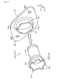
- FIG. 17 is an exploded perspective view of the connector of FIG.
- This power conversion device is mounted on a vehicle such as an electric vehicle or a hybrid vehicle, and is configured as an in-vehicle power conversion device that converts power between DC power and AC power.
- the first direction which is the stacking direction of a plurality of cooling pipes arranged in parallel with each other in the cooler, is indicated by an arrow X
- the second direction in which each cooling pipe extends is indicated by an arrow Y
- the third direction orthogonal to both the first direction and the second direction is indicated by an arrow Z.
- the power converter 1 of the first embodiment generally includes a plurality of semiconductor modules 10, a cooler 20, and a case 30.
- the case 30 is configured as a metal container that houses a plurality of semiconductor modules 10, a cooler 20, and a plurality of other elements.
- the plurality of elements include a capacitor 2, a control board 3, a reactor 4, and a DC-DC converter 5.
- the capacitor 2 has a capacitor element 2a and a pair of metal electrodes 2p and 2n.
- One of the metal electrodes 2p is electrically connected to the positive electrode terminal 11p of the switching element 11 built in the semiconductor module 10 via a metal bus bar 6.
- the other metal electrode 2n is electrically connected to the negative electrode terminal 11n of the switching element 11 of the semiconductor module 10 via a metal bus bar 7.
- the cooler 20 has a function of cooling a plurality of semiconductor modules 10 by using a cooling medium (hereinafter, simply referred to as “refrigerant”).
- the cooler 20 is a laminated cooler, and includes a plurality of cooling pipes 21 that are laminated and arranged together with the plurality of semiconductor modules 10.
- the plurality of cooling pipes 21 are arranged in parallel with each other with a space 21a in which the plurality of semiconductor modules 10 are interposed, and are laminated in the first direction X.
- the cooling pipe 21 extends in a long shape in the second direction Y, and has a rectangular cross-sectional shape (cross-sectional shape in a plane defined by the first direction X and the third direction Z) with respect to the first direction X. ..
- the cooling pipe 21 is connected in parallel to each of the introduction pipe 22 and the discharge pipe 23.
- the cooling pipe 21 is configured as a heat exchange unit capable of exchanging heat with the semiconductor module 10. Therefore, the cooling pipe 21 is preferably made of a material having high thermal conductivity, for example, a metal material such as aluminum.
- the outer cooling pipe 21A of the plurality of cooling pipes 21 is pressurized to the right side in FIG. 1 by the leaf spring 27 for pressurizing.
- the leaf spring 27 is supported by a support pin 28 fixed to the case 30.
- Both the introduction pipe 22 and the discharge pipe 23 extend in the first direction X, which is the stacking direction of the plurality of cooling pipes 21, and reach the case 30 via the connector 40 in each of the first region R1 and the second region R2. It is fixed.
- An external pipe E such as a rubber hose is connected to the connector 40.
- the introduction pipe 22 and the discharge pipe 23 are preferably made of the same material as the cooling pipe 21, for example, a metal material such as aluminum.
- the introduction pipe 22 is a pipe for introducing the refrigerant into the cooling pipe 21, and the discharge pipe 23 is a pipe for discharging the refrigerant from the cooling pipe 21.
- the refrigerant introduced from the introduction pipe 22 flows in parallel with the plurality of cooling pipes 21 in the second direction, and when flowing through the refrigerant flow path in each cooling pipe 21, both sides of the first direction X of the cooling pipe 21 After cooling the semiconductor module 10 located in, it is discharged from the discharge pipe 23.
- Typical refrigerants include water mixed with ethylene glycol-based antifreeze, natural refrigerants such as water and ammonia, fluorocarbon-based refrigerants such as Florinate, chlorofluorocarbon-based refrigerants such as HCFC123 and HFC134a, and alcohol-based refrigerants such as methanol and alcohol.
- a ketone refrigerant such as acetone can be used.
- the semiconductor module 10 is a 2in1 type module in which two switching elements 11 are built in the module body.
- the semiconductor module 10 includes a pair of electrode terminals, the positive electrode terminal 11p and the negative electrode terminal 11n, an output terminal 12 connected to the positive electrode of an auxiliary battery (auxiliary battery B2 in FIG. 4) described later, and a control board 3. Among them, a plurality of control terminals 13 connected to a control circuit for driving and controlling the switching element 11 are provided.
- the power conversion device 1 has an inverter circuit 70 which is a power conversion circuit that converts DC power supplied from DC power supply B1 into AC power.
- the inverter circuit 70 the plurality of semiconductor modules 10 are electrically connected to the control board 3, and the switching operation (on / off operation) is controlled by the control board 3.
- the control board 3 is fixed to the case 30 as shown in FIG.
- the capacitor 2A, the reactor 4, and the two semiconductor modules 10A constitute a booster portion 71 of the inverter circuit 70, which is a power conversion circuit.
- the boosting unit 71 has a function of boosting the voltage of the DC power supply B1 by a switching operation (on / off operation) of the semiconductor module 10A.
- the capacitor 2A is a capacitor for removing the noise current included in the current supplied from the DC power supply B1, and is also called a filter capacitor. Like the capacitor 2 described above, the capacitor 2A is configured as a capacitor having a film capacitor element.
- the reactor 4 is a passive element using an inductor.
- the capacitor 2 and the six semiconductor modules 10B constitute a conversion unit 72 of the inverter circuit 70, which is a power conversion circuit.
- the conversion unit 72 has a function of converting DC power after being boosted by the boosting unit 71 into AC power by a switching operation (on / off operation) of the semiconductor module 10B.
- the capacitor 2 is a capacitor for smoothing the DC power boosted by the booster 71, and is also called a smoothing capacitor.
- the AC power obtained by the conversion unit 72 drives the three-phase AC motor M for traveling the vehicle.
- the DC-DC converter 5 is connected to the DC power supply B1.
- the DC-DC converter 5 is used to step down the voltage of the DC power supply B1 and charge the auxiliary battery B2 having a lower voltage than the DC power supply B1.
- the auxiliary battery B2 is used as a power source for various devices mounted on the vehicle.
- the current flowing through the booster 71 is detected by the current sensor 73. Further, the current flowing between the conversion unit 72 and the three-phase AC motor M is detected by the current sensors 74 and 75.
- the current sensors 73, 74, 75 are electrically connected to the control board 3, and the detection information by the current sensors 73, 74, 75 is transmitted to the control board 3.
- the power conversion device 1 includes a connector 40, a first sealing member 50, and a second sealing member 60.
- the introduction pipe 22 as a refrigerant flow pipe is inserted through a through hole 31 formed through the case 30, and the tip portion is configured to project to the outside of the case 30.
- the introduction pipe 22 is configured to be connected to one connector 40 outside the case 30 (see the first region R1 in FIG. 1).
- the space between the introduction pipe 22 and the connector 40 is sealed by the first sealing member 50.
- the connector 40 has a tubular pipe portion 41 that communicates with the introduction pipe 22, and a flange portion 45 that is fixed to the case 30 by a plurality of fastening members 8.
- the pipe portion 41 and the flange portion 45 are both made of a metal material and are integrally joined. Therefore, the connector 40 is made of a metal material.
- a metal material of the connector 40 a stainless steel material having high corrosion resistance to a refrigerant can be typically used.
- the pipe portion 41 sandwiches an inner cylinder portion 42 having an inner diameter larger than the outer diameter of the introduction pipe 22, a disc-shaped protruding portion 43 protruding outward in the radial direction from the inner cylinder portion 42, and an inner cylinder portion 42. It has a protrusion 44 that protrudes outward in the radial direction from a position opposite to the protrusion 43.
- the tip of the introduction pipe 22 is inserted inside the inner cylinder portion 42 of the pipe portion 41. Further, an external pipe E (see FIG. 1) communicating with the introduction pipe 22 is connected to the pipe portion 41. Therefore, the pipe portion 41 constitutes a substantial connector 40.
- the flange portion 45 includes a cylindrical outer cylinder portion 46 arranged on the outer periphery of the inner cylinder portion 42 of the pipe portion 41, a disc-shaped flange portion 48 extending radially outward from the outer cylinder portion 46, and the flange portion 45.
- the in-cylinder space of the outer cylinder portion 46 is configured as an insertion hole 47 into which the inner cylinder portion 42 of the pipe portion 41 is inserted. Therefore, the outer cylinder portion 46 becomes the opening edge portion of the insertion hole 47.
- the flange portion 48 is provided with a plurality of mounting holes 48a into which the shaft portion of the fastening member 8 is inserted.
- the outer cylinder portion 46 is sandwiched between the protrusion portion 43 and the protrusion portion 44, which are adjacent to the outer cylinder portion 46 and project outward in the radial direction in the pipe portion 41.
- the protruding portion 43 and the protruding portion 44 constitute an axial regulation portion that regulates the relative movement of the pipe portion 41 and the flange portion 45 in the first direction X, which is the axial direction of the pipe portion 41.
- the first sealing member 50 includes a tubular portion 51 as a connector-side tubular portion, a disc-shaped flange portion 52 extending radially outward from the tubular portion 51, and a first protrusion for watertight sealing. It has a protruding portion 53 as a portion and a protruding portion 54 as a second protruding portion for watertight sealing.
- the first sealing member 50 is simply referred to as a "sealing member 50".
- the sealing member 50 has a metal core material 50a that forms a skeleton portion, and a resin portion that covers the periphery of the core material 50a with a resin material.
- the protruding portions 53 and 54 of the sealing member 50 are formed by resin portions around the core material 50a.
- the sealing member 50 is assembled to the case 30 together with the connector 40 in a state of being inserted in the insertion direction D2 with respect to the connector 40.
- the tubular portion 51 of the sealing member 50 is interposed between the inner peripheral surface 40a of the connector 40 and the outer peripheral surface 22a of the introduction pipe 22.
- the flange portion 52 is arranged so as to sandwich the protruding portion 43 of the pipe portion 41 with the flange portion 45 in the first direction X.
- the projecting portion 53 is configured as an annular projecting portion that projects radially outward from the tubular portion 51 toward the inner peripheral surface 40a of the connector 40.
- the cross-sectional shape of the protruding portion 53 with respect to the plane determined by the first direction X and the third direction Z is a substantially trapezoidal shape such that the width of the first direction X gradually decreases outward in the radial direction. Therefore, the trapezoidal lip seal structure is formed by the protruding portion 53.
- the protruding portion 53 comes into contact with the inner peripheral surface 40a of the connector 40. At this time, the protruding portion 53 is compressed by the inner peripheral surface 40a of the connector 40 and elastically deformed to exhibit watertight sealing performance.
- the protruding portion 54 is configured as an annular protruding portion that protrudes inward in the radial direction from the tubular portion 51 toward the outer peripheral surface 22a of the introduction pipe 22.
- the protruding portion 54 is provided on an arm portion extending to the right in FIG. 5 from a portion corresponding to the right tip portion of the core material 50a as a whole.
- the cross-sectional shape of the arm portion with respect to the plane determined by the first direction X and the third direction Z is such that two annular protrusions 54 are arranged apart from each other in the first direction X. Therefore, a double lip seal structure is formed by the two protrusions 54.
- each of the protrusions 54 When the two protrusions 54 come into contact with the outer peripheral surface 22a of the introduction pipe 22, each of the protrusions 54 is compressed by the outer peripheral surface 22a of the introduction pipe 22 and elastically deformed to exhibit watertight sealing performance.
- the arm portion By lengthening the flexible resin arm portion in the protruding portion 54, the arm portion elastically deforms following the eccentricity of the introduction pipe 22 to maintain high watertight sealing performance. Can be done.
- the protruding portion 54 having such a shape is excellent in followability to the eccentricity of the introduction pipe 22.
- Both the protruding portion 53 and the protruding portion 54 have a shape in which the protruding portion is elongated in the circumferential direction in an annular shape, and extend on a plane determined by the second direction Y and the third direction Z.
- one protruding portion 53 is arranged on the outer surface of the tubular portion 51, and two protruding portions 54 are arranged on the inner surface of the tubular portion 51 at intervals in the first direction X.
- the number, arrangement, and shape of the protrusions 53 and 54 are not limited to the above, and can be appropriately changed as needed. That is, the number of protrusions 53 and 54 may be the same, or the number of protrusions 53 and 54 may be different. Further, as the cross-sectional shape of the protruding portion 53, a shape such as a rectangle in which the width of the first direction X is substantially constant can be adopted. In order to improve the sealing performance, it is preferable to increase the number of the protrusions 53 and 54.
- the second sealing member 60 seals between the through hole 31 of the case 30 and the introduction pipe 22 at a position closer to the cooling pipe 21 of the cooler 20 than the sealing member 50 in the first direction X. It is provided.
- the second sealing member 60 is configured as a separate member from the sealing member 50.
- the second sealing member 60 includes a tubular portion 61 as a case-side tubular portion, a disc-shaped flange portion 62 extending radially outward from the tubular portion 61, and a first airtight sealing member. It has a protruding portion 63 as a protruding portion and a protruding portion 64 as a second protruding portion for airtight sealing.
- the second sealing member 60 is simply referred to as a “sealing member 60”.
- the sealing member 60 has a metal core material 60a forming a skeleton portion and a resin portion that covers the periphery of the core material 60a with a resin material.
- the protruding portions 63 and 64 of the sealing member 60 are formed by resin portions around the core material 60a.
- the sealing member 60 is assembled to the case 30 by being inserted into the case 30 in the insertion direction D1.
- the tubular portion 61 of the sealing member 60 is interposed between the inner peripheral surface 31a of the through hole 31 of the case 30 and the outer peripheral surface 22a of the introduction pipe 22.
- the collar portion 62 is arranged so as to abut from the outside on the end surface 32 of the case 30 in the first direction X.
- the insertion direction D1 of the sealing member 60 corresponds to the insertion direction D1 of the sealing member 50. Further, the insertion direction D2 of the sealing member 60 corresponds to the insertion direction D2 of the sealing member 50.
- the flange portion 62 of the sealing member 60 is provided so as to overlap the flange portion 52 of the sealing member 50 in the insertion direction D1 of the sealing member 50.
- the flange portion 62 is sized so as to overlap the flange portion 52 of the sealing member 50 in the insertion direction D1.
- the flange portion 62 becomes a first sealing member regulating portion that regulates the movement of the sealing member 50 in the insertion direction D1.
- the sealing member 50 is less likely to come off, and the watertight sealing performance of the sealing member 50 can be maintained.
- the projecting portion 63 is configured as an annular projecting portion that projects radially outward from the tubular portion 61 toward the inner peripheral surface 31a of the through hole 31 of the case 30.
- the cross-sectional shape of the protruding portion 63 with respect to the plane determined by the first direction X and the third direction Z is a substantially trapezoidal shape such that the width of the first direction X gradually decreases outward in the radial direction. Therefore, the trapezoidal lip seal structure is formed by the protruding portion 63.
- the protruding portion 63 comes into contact with the inner peripheral surface 31a of the through hole 31. At this time, the protruding portion 63 is compressed by the inner peripheral surface 31a of the through hole 31 and elastically deformed to exhibit airtight sealing performance.
- the hooking portion 63a exerts a function of preventing the sealing member 60 from coming off by being hooked on the locking portion 33 of the case 30.
- the locking portion 33 of the case 30 is chamfered with a C chamfered corner.
- the locking portion 33 may be provided in an annular shape in the circumferential direction, or may be partially provided in the circumferential direction.
- the protruding portion 64 is configured as an annular protruding portion that protrudes inward in the radial direction from the tubular portion 61 toward the outer peripheral surface 22a of the introduction pipe 22.
- the protruding portion 64 is provided on an arm portion extending to the right in FIG. 5 from a portion corresponding to the left tip portion of the core material 60a as a whole.
- the cross-sectional shape of the plane determined by the first direction X and the third direction Z is such that two annular protrusions 64 are arranged so as to be separated from each other in the first direction X. Therefore, a double lip seal structure is formed by the two protrusions 64.
- each of the protrusions 64 When the two protrusions 64 come into contact with the outer peripheral surface 22a of the introduction pipe 22, each of the protrusions 64 is compressed by the outer peripheral surface 22a of the introduction pipe 22 and elastically deformed to exhibit airtight sealing performance.
- the arm portion By lengthening the flexible resin arm portion in the protruding portion 64, the arm portion elastically deforms following the eccentricity of the introduction pipe 22 to maintain high watertight sealing performance. Can be done.
- the protruding portion 64 having such a shape is excellent in followability to the eccentricity of the introduction pipe 22.
- Both the protruding portion 63 and the protruding portion 64 have a shape in which the protruding portion is extended in the circumferential direction in an annular shape, and extend on a plane determined by the second direction Y and the third direction Z.
- one protruding portion 63 is arranged on the outer surface of the tubular portion 61, and two protruding portions 64 are arranged on the inner surface of the tubular portion 61 at intervals in the first direction X. Further, each of the two protrusions 63 and each of the two protrusions 64 are configured to overlap each other in the third direction Z.
- the number, arrangement, and shape of the protrusions 63 and 64 are not limited to the above, and can be appropriately changed as needed. That is, the number of protrusions 63 and 64 may be the same, or the number of protrusions 63 and 64 may be different. Further, as the cross-sectional shape of the protruding portion 63, a shape such as a rectangle in which the width of the first direction X is substantially constant can be adopted. In order to improve the sealing performance, it is preferable to increase the number of the protrusions 63 and 64.
- the protrusion 54 of the sealing member 50 is larger than the protrusion 53 in order to enhance the sealing performance on the introduction pipe 22 side having a lower corrosion resistance.
- the number of protrusions 64 can be increased in the sealing member 60, or the number of protrusions 64 can be increased more than that of the protrusions 63.
- a gap 55 in the first direction X is formed between the first facing surface 52a of the flange portion 52 of the sealing member 50 and the second facing surface 62a of the flange portion 62 of the sealing member 60.
- the first facing surface 52a and the second facing surface 62a face each other in the first direction X.
- the gap 55 constitutes a refrigerant discharge path leading from the space between the sealing member 50 and the outer peripheral surface 22a of the introduction pipe 22 to the outside of the case 30.
- the gap 55 has a function of discharging the refrigerant to the outside of the case 30 when the refrigerant flows into the space on the outer peripheral surface 22a side of the introduction pipe 22. According to the gap 55, it is possible to prevent the refrigerant from flowing into the case 30.
- the discharge pipe 23 as a refrigerant flow pipe is inserted through a through hole 31 formed through the case 30 like the introduction pipe 22, and the tip portion protrudes to the outside of the case 30. It is configured to do.
- the discharge pipe 23 is configured to be connected to a connector 40 similar to that of the introduction pipe 22 outside the case 30 (see the second region R2 in FIG. 1).
- the space between the discharge pipe 23 and the connector 40 is sealed by a sealing member 50 similar to that of the introduction pipe 22.
- the connector 40 is configured such that the tubular pipe portion 41 communicates with the discharge pipe 23.
- the inner cylinder portion 42 of the pipe portion 41 has an inner diameter that exceeds the outer diameter of the discharge pipe 23.
- the tip of the discharge pipe 23 is inserted inside the inner cylinder portion 42.
- an external pipe E (see FIG. 1 omitted) communicating with the discharge pipe 23 is connected to the pipe portion 41.
- the sealing member 50 and the sealing member 60 are the same as in the case of the introduction pipe 22, and only the differences will be described.
- the tubular portion 51 of the sealing member 50 is interposed between the inner peripheral surface 40a of the connector 40 and the outer peripheral surface 23a of the discharge pipe 23.
- the protruding portion 53 projects radially outward from the tubular portion 51 toward the inner peripheral surface 40a of the connector 40, and the protruding portion 54 protrudes outward from the tubular portion 51 toward the outer peripheral surface of the discharge pipe 23. It protrudes inward in the radial direction toward 23a.
- the tubular portion 61 of the sealing member 60 is interposed between the inner peripheral surface 31a of the through hole 31 of the case 30 and the outer peripheral surface 23a of the discharge pipe 23.
- the projecting portion 63 projects radially outward from the tubular portion 61 toward the inner peripheral surface 31a of the through hole 31 of the case 30, and the projecting portion 64 projects from the tubular portion 61 to the introduction pipe. It projects inward in the radial direction toward the outer peripheral surface 22a of 22.
- the gap 55 formed between the sealing member 50 and the sealing member 60 constitutes a refrigerant discharge path leading from the space on the outer peripheral surface 23a side of the discharge pipe 23 to the outside of the case 30.
- the gap 55 has a function of discharging the refrigerant to the outside of the case 30 when the refrigerant flows into the space on the outer peripheral surface 23a side of the discharge pipe 23.
- the sealing member 50 is pre-assembled to the connector 40 and the sealing member 60 is pre-assembled to the case 30 before connecting the connector 40 to the introduction pipe 22 protruding from the case 30. ..
- the sealing member 50 is assembled to the connector 40 by pushing the tubular portion 51 inserted into the cylinder of the connector 40 in the insertion direction D2 until the flange portion 52 abuts on the connector 40. At this time, the protruding portion 53 of the sealing member 50 slides on the inner peripheral surface 40a of the connector 40.
- the sealing member 60 pushes the tubular portion 61 inserted into the through hole 31 of the case 30 after being inserted into the introduction pipe 22 in the insertion direction D1 until the flange portion 62 abuts on the case 30, thereby pushing the case 30. It is assembled to. At this time, the protruding portion 63 of the sealing member 60 slides on the inner peripheral surface 31a of the through hole 31 of the case 30, and the protruding portion 64 of the sealing member 60 slides on the outer peripheral surface 22a of the introduction pipe 22.
- the sealing member 60 is hooked on the locking portion 33 by the hooking portion 63a formed by protruding outward in the radial direction from the protruding portion 63. It is locked to the case 30.
- the locking portion 33 of the case 30 functions as a second sealing member regulating portion that regulates the movement of the sealing member 60 in the insertion direction D2 by being caught by the hooking portion 63a of the protruding portion 63. Fulfill. Further, since the locking portion 33 is C-chamfered, it is effective in preventing damage to the sealing member 60.
- the case 30 and the connector 40 are brought close to each other, and the introduction pipe 22 is inserted into the tubular portion 51 of the sealing member 50.
- the protruding portion 54 of the sealing member 50 slides on the outer peripheral surface 22a of the introduction pipe 22.
- the connector 40 is fastened to the case 30 via the fastening member 8 inserted into the mounting hole 48a of the flange portion 45 (see FIG. 5).
- the pipe portion 41 and the flange portion 45 are joined to each other in a state where the pipe portion 41 is inserted into the insertion hole 47 of the flange portion 45.
- the protruding portion 43 of the pipe portion 41 is configured such that the annular end surface extending in the circumferential direction forms an uneven surface (stepped surface) in the first direction X.
- the uneven surface is formed by alternately arranging the engaging convex portion 43a and the engaging concave portion 43b in the circumferential direction with respect to the outer cylinder portion 46 of the flange portion 45.
- the outer cylinder portion 46 of the flange portion 45 is configured such that the annular end surface extending in the circumferential direction forms an uneven surface (stepped surface) in the first direction X.
- the uneven surface is formed by alternately arranging the engaging convex portion 46a and the engaging concave portion 46b in the circumferential direction with respect to the protruding portion 43 of the pipe portion 41.
- the plurality of engaging convex portions 43a on the pipe portion 41 side are fitted into the plurality of engaging concave portions 46b on the flange portion 45 side, and the plurality of engaging convex portions 46a on the flange portion 45 side are the pipe portions.
- It has a fitting structure that is fitted into a plurality of engaging recesses 43b on the 41 side.
- This fitting structure functions as a circumferential regulation portion that regulates the relative movement of the pipe portion 41 and the flange portion 45 in the circumferential direction of the pipe portion.
- This fitting structure has an engaging convex portion 43a and an engaging concave portion 43b as a first engaging portion provided on the pipe portion 41, and an engaging convex portion 43a and an engaging concave portion 43b of the pipe portion 41 on the flange portion 45. It is composed of an engaging concave portion 46b and an engaging convex portion 46a as a second engaging portion that engages with.
- the numbers of the engaging convex portion 43a, the engaging concave portion 43b, the engaging convex portion 46a, and the engaging concave portion 46b can be appropriately changed as needed.
- the fitting structure of the connector 40 is formed by caulking, which is one of plastic working. This caulking process will be described with reference to FIGS. 10 to 15.
- caulking of the connector 40 can be performed by sequentially executing the operations from the first step S101 to the fifth step S105. If necessary, one or a plurality of steps may be added to this flowchart, each step may be divided into a plurality of steps, or a plurality of steps may be integrated.
- the first step S101 in FIG. 10 is a step of temporarily assembling the pipe portion 41A and the flange portion 45A before caulking.
- the outer cylinder portion 46 of the flange portion 45A is previously formed with engaging convex portions 46a and engaging concave portions 46b alternately in the circumferential direction, and an insertion hole 47 which is an inner space of the outer cylinder portion 46.
- the pipe portion 41A is inserted into the pipe (see FIG. 11).
- the protruding portion 44 see FIGS. 5 and 6) of the pipe portion 41A abuts on the outer cylinder portion 46 of the flange portion 45A
- the pipe portion 41A has one end portion 42a of the inner cylinder portion 42 thereof. It is positioned with respect to the flange portion 45A in a state of being exposed from the outer cylinder portion 46.
- the caulking jig 80 is used for caulking the pipe portion 41A and the flange portion 45.
- the caulking jig 80 has a deformation prevention guide 81, a first punch 82, a second punch 83, and a load receiving 84 (see FIG. 13).
- the deformation prevention guide 81 is for preventing the inner cylinder portion 42 of the pipe portion 41A from being deformed during caulking.
- the deformation prevention guide 81 is configured as a columnar member having an outer diameter similar to the inner diameter of the inner cylinder portion 42 of the pipe portion 41A.
- the first punch 82 is responsible for the initial stage processing of deforming the end portion 42a into the protruding portion 43 by pressing one end portion 42a of the inner cylinder portion 42 of the pipe portion 41A.
- the first punch 82 is configured as a truncated cone-shaped member having a tapered pressing surface 82a.
- the second punch 83 is used after the use of the first punch 82.
- the second punch 83 is responsible for the final stage processing of deforming the end portion 42a into the protruding portion 43 by pressing the end portion 42a of the inner cylinder portion 42 of the pipe portion 41A.
- the second punch 83 has a pressing surface having a circular pressing surface in a plan view for pressing the end portion 42a of the inner cylinder portion 42 of the pipe portion 41A, and the convex surface 83a and the concave surface 83b are alternately arranged in the circumferential direction. It is formed by being done.
- the load receiving 84 is for receiving the pressing load received from each of the first punch 82 and the second punch 83.
- the second step S102 of FIG. 10 is a step of inserting the deformation prevention guide 81 into the cylinder of the inner cylinder portion 42 of the pipe portion 41A after the first step S101.
- the deformation prevention guide 81 is the inner cylinder portion 42 of the pipe portion 41A in a state where the pipe portion 41A and the flange portion 45A are set with respect to the load receiving 84. It is inserted into the cylinder of.
- the third step S103 in FIG. 10 is a step in which processing is performed by the first punch 82 after the second step S102.
- the end portion 42a of the inner cylinder portion 42 of the pipe portion 41A is pressed outward through the pressing surface 82a of the first punch 82 in the radial direction. It is pushed out.
- the fourth step S104 of FIG. 10 is a step of performing processing by the second punch 83 following the third step S103.
- the end portion 42a of the inner cylinder portion 42 of the pipe portion 41A is pressed through the pressing surface of the second punch 83 and further outward in the radial direction. It is pushed out.
- the end portion 42a of the inner cylinder portion 42 of the pipe portion 41A is plastically deformed together with the outer cylinder portion 46 of the flange portion 45A by the plurality of convex surfaces 83a and concave surfaces 83b forming the pressing surface of the second punch 83.
- each convex surface 83a of the second punch 83 forms each engaging convex portion 43a of the protruding portion 43 at the end portion 42a of the inner cylinder portion 42, and each engaging convex portion 43a. 43a fits into each engaging recess 46b of the outer cylinder portion 46. Further, each concave surface 83b of the second punch 83 presses the engaging concave portion 43b of the protruding portion 43 to fit with each engaging convex portion 46a of the outer cylinder portion 46. As a result, a connector 40 is formed in which the pipe portion 41 and the flange portion 45 are joined to each other by caulking.
- the fifth step S105 in FIG. 10 is a step of extracting the deformation prevention guide 81 from the connector 40 after the fourth step S104.
- the cooling tube 21 which is the heat exchange unit of the cooler 20 can exchange heat with the semiconductor module 10 incorporating the switching element 11.
- the connector 40 is connected to each of the introduction pipe 22 and the discharge pipe 23 of the cooler 20 outside the case 30.
- the connector 40 is interposed between the introduction pipe 22 or the discharge pipe 23 of the cooler 20 and the external pipe E.
- the pipe portion 41 and the flange portion 45 are joined to each other by caulking while the pipe portion 41, which is a member different from the flange portion 45, is inserted into the insertion hole 47 of the flange portion 45. It is configured to.
- the connector 40 interposed between the introduction pipe 22 or the discharge pipe 23, which is the refrigerant flow pipe of the cooler 20 for the semiconductor module 10, and the external pipe E is low. It is possible to provide a power conversion device 1 that can increase versatility at low cost.
- the pipe portion 41 and the flange portion 45 are in the axial direction by sandwiching the outer cylinder portion 46 of the flange portion 45 between the protruding portions 43 and the protruding portions 44 of the pipe portion 41. It is possible to regulate the relative movement in the first direction X.
- the engaging convex portion 43a and the engaging concave portion 43b provided on the protruding portion 43 of the pipe portion 41 and the engaging concave portion 43b provided on the outer cylinder portion 46 of the flange portion 45 are engaged.
- the convex portion 46a and the engaging concave portion 46b are fitted to each other, it is possible to restrict the relative movement of the pipe portion 41 and the flange portion 45 in the circumferential direction.
- the protruding portion 43 of the pipe portion 41 has a function of regulating the relative movement of the pipe portion 41 and the flange portion 45 in the axial direction and a function of regulating the relative movement of the pipe portion 41 and the flange portion 45 in the circumferential direction. It has both functions.
- the pipe portion 41 and the flange portion 45 can be integrally joined by using caulking. As a result, the mold cost required for molding can be reduced, and the pipe portion 41 and the flange portion 45 can be joined at low cost.
- the axially restricting portion for restricting the relative movement of the pipe portion 41 and the flange portion 45 in the axial direction is any of the protruding portion 43 and the protruding portion 44. It may be composed of one of them, or may be composed of a portion different from the protruding portion 43 and the protruding portion 44.
- the power conversion device 101 of the second embodiment is different from that of the first embodiment in terms of the structure of the connector 140. Others are the same as in the first embodiment.
- a plurality of protruding portions 43 of the pipe portion 41A project from the end portion 42a of the inner cylinder portion 42 along the first direction X and are arranged at substantially equal intervals in the circumferential direction. It is composed of the engaging piece 43c of.
- the plurality of engaging pieces 43c are bent outward in the radial direction by using bending processing which is plastic working. Becomes a pipe portion 41 (see FIG. 16).
- a plurality of engaging grooves 46c are provided at substantially equal intervals in the circumferential direction on the annular end surface of the outer cylinder portion 46 of the flange portion 45.
- the plurality of engaging grooves 46c are formed by utilizing plastic working such as press working, notch working, and bending work.
- each of the plurality of engaging pieces 43c bent outward in the radial direction in the pipe portion 41 is fitted into each of the plurality of engaging grooves 46c of the flange portion 45.
- the connector 140 is formed by.
- the connector 140 has a fitting structure in which the plurality of engaging pieces 43c on the pipe portion 41 side are fitted into the plurality of engaging grooves 46c on the flange portion 45 side.
- This fitting structure functions as a circumferential regulation portion that regulates the relative movement of the pipe portion 41 and the flange portion 45 in the circumferential direction of the pipe portion.
- the pipe portion 41 and the flange portion 45 can be integrally joined by using plastic working other than caulking.
- the connectors 40 and 140 are connected to the introduction pipe 22 and the discharge pipe 23 of the cooler 20 has been illustrated, but instead, it is connected to either the introduction pipe 22 or the discharge pipe 23.
- the connectors 40 and 140 may be connected, and a connector having a structure different from that of the connectors 40 and 140 may be connected to either one of them.
- the connectors 40 and 140 made of a metal material have been illustrated, but instead, the connectors 40 and 140 made of a material different from the metal material such as a resin material are adopted. You can also.
- the laminated cooler 20 for cooling the plurality of semiconductor modules 10 has been illustrated, but the heat exchange unit capable of exchanging heat with the semiconductor module and the introduction pipe for introducing the refrigerant into the heat exchange unit.
- the structure of the cooler is not limited to the laminated type as long as it has a discharge pipe for discharging the refrigerant from the heat exchange section, and a cooler having a different structure may be adopted if necessary. it can.
Landscapes
- Engineering & Computer Science (AREA)
- Microelectronics & Electronic Packaging (AREA)
- Physics & Mathematics (AREA)
- Power Engineering (AREA)
- Condensed Matter Physics & Semiconductors (AREA)
- General Physics & Mathematics (AREA)
- Computer Hardware Design (AREA)
- Thermal Sciences (AREA)
- Inverter Devices (AREA)
- Cooling Or The Like Of Semiconductors Or Solid State Devices (AREA)
Priority Applications (1)
| Application Number | Priority Date | Filing Date | Title |
|---|---|---|---|
| US17/510,771 US12178023B2 (en) | 2019-04-26 | 2021-10-26 | Power conversion device |
Applications Claiming Priority (2)
| Application Number | Priority Date | Filing Date | Title |
|---|---|---|---|
| JP2019-086339 | 2019-04-26 | ||
| JP2019086339A JP7003967B2 (ja) | 2019-04-26 | 2019-04-26 | 電力変換装置 |
Related Child Applications (1)
| Application Number | Title | Priority Date | Filing Date |
|---|---|---|---|
| US17/510,771 Continuation US12178023B2 (en) | 2019-04-26 | 2021-10-26 | Power conversion device |
Publications (1)
| Publication Number | Publication Date |
|---|---|
| WO2020217984A1 true WO2020217984A1 (ja) | 2020-10-29 |
Family
ID=72941891
Family Applications (1)
| Application Number | Title | Priority Date | Filing Date |
|---|---|---|---|
| PCT/JP2020/015764 Ceased WO2020217984A1 (ja) | 2019-04-26 | 2020-04-08 | 電力変換装置 |
Country Status (3)
| Country | Link |
|---|---|
| US (1) | US12178023B2 (enExample) |
| JP (1) | JP7003967B2 (enExample) |
| WO (1) | WO2020217984A1 (enExample) |
Families Citing this family (2)
| Publication number | Priority date | Publication date | Assignee | Title |
|---|---|---|---|---|
| JP7427916B2 (ja) * | 2019-10-31 | 2024-02-06 | セイコーエプソン株式会社 | 流路部材、流路ユニット、および、液体噴射装置 |
| DE102021210153A1 (de) * | 2021-09-14 | 2023-03-16 | Robert Bosch Gesellschaft mit beschränkter Haftung | Elektronikanordnung |
Citations (3)
| Publication number | Priority date | Publication date | Assignee | Title |
|---|---|---|---|---|
| WO2013118346A1 (ja) * | 2012-02-07 | 2013-08-15 | Kobayashi Kazumi | フランジ継手接続構造 |
| JP2014009761A (ja) * | 2012-06-29 | 2014-01-20 | Sekisui Chem Co Ltd | フランジ付管体 |
| JP2015053763A (ja) * | 2013-09-05 | 2015-03-19 | 株式会社デンソー | 電力変換装置 |
Family Cites Families (9)
| Publication number | Priority date | Publication date | Assignee | Title |
|---|---|---|---|---|
| US5797602A (en) * | 1996-10-10 | 1998-08-25 | Pac-Seal Inc. International | Mechanical seal for water pump of heavy duty vehicle |
| JP4026820B2 (ja) * | 2002-12-09 | 2007-12-26 | 太平洋工業株式会社 | ノズルキャップ |
| JP4552805B2 (ja) * | 2005-08-19 | 2010-09-29 | 株式会社デンソー | 積層型熱交換器及びその製造方法 |
| US8573178B2 (en) * | 2009-02-24 | 2013-11-05 | Pinnacle Engines, Inc. | Sleeve valve assembly |
| JP5880491B2 (ja) * | 2013-07-01 | 2016-03-09 | トヨタ自動車株式会社 | インバータケース |
| JP5862646B2 (ja) * | 2013-12-04 | 2016-02-16 | トヨタ自動車株式会社 | 冷媒管の連結構造及び冷却器内蔵インバータ |
| US10487678B2 (en) * | 2016-05-23 | 2019-11-26 | United Technologies Corporation | Engine air sealing by seals in series |
| JP6658710B2 (ja) * | 2016-11-21 | 2020-03-04 | 株式会社デンソー | 積層型熱交換器 |
| US11028712B2 (en) * | 2019-03-27 | 2021-06-08 | Raytheon Technologies Corporation | Seal support feature for brush seals |
-
2019
- 2019-04-26 JP JP2019086339A patent/JP7003967B2/ja active Active
-
2020
- 2020-04-08 WO PCT/JP2020/015764 patent/WO2020217984A1/ja not_active Ceased
-
2021
- 2021-10-26 US US17/510,771 patent/US12178023B2/en active Active
Patent Citations (3)
| Publication number | Priority date | Publication date | Assignee | Title |
|---|---|---|---|---|
| WO2013118346A1 (ja) * | 2012-02-07 | 2013-08-15 | Kobayashi Kazumi | フランジ継手接続構造 |
| JP2014009761A (ja) * | 2012-06-29 | 2014-01-20 | Sekisui Chem Co Ltd | フランジ付管体 |
| JP2015053763A (ja) * | 2013-09-05 | 2015-03-19 | 株式会社デンソー | 電力変換装置 |
Also Published As
| Publication number | Publication date |
|---|---|
| JP2020182363A (ja) | 2020-11-05 |
| US12178023B2 (en) | 2024-12-24 |
| US20220046831A1 (en) | 2022-02-10 |
| JP7003967B2 (ja) | 2022-01-21 |
Similar Documents
| Publication | Publication Date | Title |
|---|---|---|
| JP5991345B2 (ja) | 電力変換装置 | |
| US9941187B2 (en) | Power converter and method for manufacturing power converter | |
| JP5012389B2 (ja) | 電力変換装置 | |
| US20160192539A1 (en) | Stack unit | |
| JP2011182630A (ja) | 電力変換装置 | |
| WO2020217984A1 (ja) | 電力変換装置 | |
| JP6696453B2 (ja) | 電力変換装置 | |
| CN106505873A (zh) | 用于冷却剂通路的连接部件和冷却系统 | |
| CN106507636B (zh) | 冷却剂通路连接结构和冷却系统 | |
| US20170301610A1 (en) | Cooler module, and method for manufacturing cooler module | |
| CN108808159A (zh) | 冷却系统、用于冷却系统的流体收集器以及用于制造流体收集器的方法 | |
| WO2015029446A1 (ja) | 積層型冷却器 | |
| JP6219780B2 (ja) | 電子機器及び電子機器に備えられる管継手 | |
| KR20180112983A (ko) | 전기소자 쿨링모듈 | |
| JP6981447B2 (ja) | 電力変換装置 | |
| JP5333274B2 (ja) | 電力変換装置 | |
| CN112053998A (zh) | 电力转换装置及其制造方法 | |
| JP2015216294A (ja) | 電子機器 | |
| JP2017017999A (ja) | 電力変換装置 | |
| JP2017103983A (ja) | 電力変換装置 | |
| CN213205962U (zh) | 卧式冷媒泵 | |
| CN116458272A (zh) | 壳体和电气装置 | |
| JP6119419B2 (ja) | 電力変換装置 | |
| CN112640269B (zh) | 用于电驱动装置或者电驱动单元的壳体组件、发动机和车辆 | |
| JP6327081B2 (ja) | 冷却器モジュール、および冷却器モジュールの製造方法 |
Legal Events
| Date | Code | Title | Description |
|---|---|---|---|
| 121 | Ep: the epo has been informed by wipo that ep was designated in this application |
Ref document number: 20795782 Country of ref document: EP Kind code of ref document: A1 |
|
| NENP | Non-entry into the national phase |
Ref country code: DE |
|
| 122 | Ep: pct application non-entry in european phase |
Ref document number: 20795782 Country of ref document: EP Kind code of ref document: A1 |