US12178023B2 - Power conversion device - Google Patents
Power conversion device Download PDFInfo
- Publication number
- US12178023B2 US12178023B2 US17/510,771 US202117510771A US12178023B2 US 12178023 B2 US12178023 B2 US 12178023B2 US 202117510771 A US202117510771 A US 202117510771A US 12178023 B2 US12178023 B2 US 12178023B2
- Authority
- US
- United States
- Prior art keywords
- pipe
- connector
- flange portion
- sealing member
- power conversion
- Prior art date
- Legal status (The legal status is an assumption and is not a legal conclusion. Google has not performed a legal analysis and makes no representation as to the accuracy of the status listed.)
- Active, expires
Links
- 238000006243 chemical reaction Methods 0.000 title claims abstract description 44
- 238000007789 sealing Methods 0.000 claims abstract description 95
- 238000001816 cooling Methods 0.000 claims abstract description 78
- 239000003507 refrigerant Substances 0.000 claims abstract description 75
- 239000004065 semiconductor Substances 0.000 claims abstract description 58
- 238000003780 insertion Methods 0.000 claims abstract description 26
- 230000037431 insertion Effects 0.000 claims abstract description 26
- 238000002788 crimping Methods 0.000 claims description 15
- 238000000034 method Methods 0.000 claims description 15
- 230000008569 process Effects 0.000 claims description 15
- 239000007769 metal material Substances 0.000 claims description 11
- 230000002093 peripheral effect Effects 0.000 description 32
- 239000003990 capacitor Substances 0.000 description 13
- 238000003825 pressing Methods 0.000 description 11
- 239000000463 material Substances 0.000 description 9
- 239000011162 core material Substances 0.000 description 8
- 229910052751 metal Inorganic materials 0.000 description 8
- 239000002184 metal Substances 0.000 description 8
- 229920003023 plastic Polymers 0.000 description 8
- 239000004033 plastic Substances 0.000 description 8
- 239000000758 substrate Substances 0.000 description 7
- LYCAIKOWRPUZTN-UHFFFAOYSA-N Ethylene glycol Chemical compound OCCO LYCAIKOWRPUZTN-UHFFFAOYSA-N 0.000 description 3
- OKKJLVBELUTLKV-UHFFFAOYSA-N Methanol Chemical compound OC OKKJLVBELUTLKV-UHFFFAOYSA-N 0.000 description 3
- 230000007797 corrosion Effects 0.000 description 3
- 238000005260 corrosion Methods 0.000 description 3
- 238000007599 discharging Methods 0.000 description 3
- 230000004048 modification Effects 0.000 description 3
- 238000012986 modification Methods 0.000 description 3
- CSCPPACGZOOCGX-UHFFFAOYSA-N Acetone Chemical compound CC(C)=O CSCPPACGZOOCGX-UHFFFAOYSA-N 0.000 description 2
- QGZKDVFQNNGYKY-UHFFFAOYSA-N Ammonia Chemical compound N QGZKDVFQNNGYKY-UHFFFAOYSA-N 0.000 description 2
- LFQSCWFLJHTTHZ-UHFFFAOYSA-N Ethanol Chemical compound CCO LFQSCWFLJHTTHZ-UHFFFAOYSA-N 0.000 description 2
- 229910052782 aluminium Inorganic materials 0.000 description 2
- XAGFODPZIPBFFR-UHFFFAOYSA-N aluminium Chemical compound [Al] XAGFODPZIPBFFR-UHFFFAOYSA-N 0.000 description 2
- 238000005452 bending Methods 0.000 description 2
- 230000007423 decrease Effects 0.000 description 2
- 238000010586 diagram Methods 0.000 description 2
- 229920002457 flexible plastic Polymers 0.000 description 2
- 238000009499 grossing Methods 0.000 description 2
- XLYOFNOQVPJJNP-UHFFFAOYSA-N water Substances O XLYOFNOQVPJJNP-UHFFFAOYSA-N 0.000 description 2
- OHMHBGPWCHTMQE-UHFFFAOYSA-N 2,2-dichloro-1,1,1-trifluoroethane Chemical compound FC(F)(F)C(Cl)Cl OHMHBGPWCHTMQE-UHFFFAOYSA-N 0.000 description 1
- 229910021529 ammonia Inorganic materials 0.000 description 1
- 230000002528 anti-freeze Effects 0.000 description 1
- 230000008859 change Effects 0.000 description 1
- 230000006835 compression Effects 0.000 description 1
- 238000007906 compression Methods 0.000 description 1
- 239000002826 coolant Substances 0.000 description 1
- 238000001514 detection method Methods 0.000 description 1
- NBVXSUQYWXRMNV-UHFFFAOYSA-N fluoromethane Chemical compound FC NBVXSUQYWXRMNV-UHFFFAOYSA-N 0.000 description 1
- 150000002576 ketones Chemical class 0.000 description 1
- 238000000465 moulding Methods 0.000 description 1
- RVZRBWKZFJCCIB-UHFFFAOYSA-N perfluorotributylamine Chemical compound FC(F)(F)C(F)(F)C(F)(F)C(F)(F)N(C(F)(F)C(F)(F)C(F)(F)C(F)(F)F)C(F)(F)C(F)(F)C(F)(F)C(F)(F)F RVZRBWKZFJCCIB-UHFFFAOYSA-N 0.000 description 1
- 229910001220 stainless steel Inorganic materials 0.000 description 1
- 239000010935 stainless steel Substances 0.000 description 1
Images


Classifications
-
- H—ELECTRICITY
- H01—ELECTRIC ELEMENTS
- H01L—SEMICONDUCTOR DEVICES NOT COVERED BY CLASS H10
- H01L23/00—Details of semiconductor or other solid state devices
- H01L23/34—Arrangements for cooling, heating, ventilating or temperature compensation ; Temperature sensing arrangements
- H01L23/40—Mountings or securing means for detachable cooling or heating arrangements ; fixed by friction, plugs or springs
- H01L23/4006—Mountings or securing means for detachable cooling or heating arrangements ; fixed by friction, plugs or springs with bolts or screws
- H01L23/4012—Mountings or securing means for detachable cooling or heating arrangements ; fixed by friction, plugs or springs with bolts or screws for stacked arrangements of a plurality of semiconductor devices
-
- H—ELECTRICITY
- H01—ELECTRIC ELEMENTS
- H01L—SEMICONDUCTOR DEVICES NOT COVERED BY CLASS H10
- H01L23/00—Details of semiconductor or other solid state devices
- H01L23/34—Arrangements for cooling, heating, ventilating or temperature compensation ; Temperature sensing arrangements
- H01L23/40—Mountings or securing means for detachable cooling or heating arrangements ; fixed by friction, plugs or springs
-
- H—ELECTRICITY
- H01—ELECTRIC ELEMENTS
- H01L—SEMICONDUCTOR DEVICES NOT COVERED BY CLASS H10
- H01L23/00—Details of semiconductor or other solid state devices
- H01L23/34—Arrangements for cooling, heating, ventilating or temperature compensation ; Temperature sensing arrangements
- H01L23/46—Arrangements for cooling, heating, ventilating or temperature compensation ; Temperature sensing arrangements involving the transfer of heat by flowing fluids
- H01L23/473—Arrangements for cooling, heating, ventilating or temperature compensation ; Temperature sensing arrangements involving the transfer of heat by flowing fluids by flowing liquids
-
- H—ELECTRICITY
- H02—GENERATION; CONVERSION OR DISTRIBUTION OF ELECTRIC POWER
- H02M—APPARATUS FOR CONVERSION BETWEEN AC AND AC, BETWEEN AC AND DC, OR BETWEEN DC AND DC, AND FOR USE WITH MAINS OR SIMILAR POWER SUPPLY SYSTEMS; CONVERSION OF DC OR AC INPUT POWER INTO SURGE OUTPUT POWER; CONTROL OR REGULATION THEREOF
- H02M7/00—Conversion of AC power input into DC power output; Conversion of DC power input into AC power output
- H02M7/42—Conversion of DC power input into AC power output without possibility of reversal
- H02M7/44—Conversion of DC power input into AC power output without possibility of reversal by static converters
- H02M7/48—Conversion of DC power input into AC power output without possibility of reversal by static converters using discharge tubes with control electrode or semiconductor devices with control electrode
- H02M7/53—Conversion of DC power input into AC power output without possibility of reversal by static converters using discharge tubes with control electrode or semiconductor devices with control electrode using devices of a triode or transistor type requiring continuous application of a control signal
- H02M7/537—Conversion of DC power input into AC power output without possibility of reversal by static converters using discharge tubes with control electrode or semiconductor devices with control electrode using devices of a triode or transistor type requiring continuous application of a control signal using semiconductor devices only, e.g. single switched pulse inverters
-
- H—ELECTRICITY
- H05—ELECTRIC TECHNIQUES NOT OTHERWISE PROVIDED FOR
- H05K—PRINTED CIRCUITS; CASINGS OR CONSTRUCTIONAL DETAILS OF ELECTRIC APPARATUS; MANUFACTURE OF ASSEMBLAGES OF ELECTRICAL COMPONENTS
- H05K7/00—Constructional details common to different types of electric apparatus
- H05K7/20—Modifications to facilitate cooling, ventilating, or heating
- H05K7/2089—Modifications to facilitate cooling, ventilating, or heating for power electronics, e.g. for inverters for controlling motor
- H05K7/20927—Liquid coolant without phase change
-
- H—ELECTRICITY
- H02—GENERATION; CONVERSION OR DISTRIBUTION OF ELECTRIC POWER
- H02M—APPARATUS FOR CONVERSION BETWEEN AC AND AC, BETWEEN AC AND DC, OR BETWEEN DC AND DC, AND FOR USE WITH MAINS OR SIMILAR POWER SUPPLY SYSTEMS; CONVERSION OF DC OR AC INPUT POWER INTO SURGE OUTPUT POWER; CONTROL OR REGULATION THEREOF
- H02M1/00—Details of apparatus for conversion
- H02M1/0067—Converter structures employing plural converter units, other than for parallel operation of the units on a single load
- H02M1/007—Plural converter units in cascade
-
- H—ELECTRICITY
- H02—GENERATION; CONVERSION OR DISTRIBUTION OF ELECTRIC POWER
- H02M—APPARATUS FOR CONVERSION BETWEEN AC AND AC, BETWEEN AC AND DC, OR BETWEEN DC AND DC, AND FOR USE WITH MAINS OR SIMILAR POWER SUPPLY SYSTEMS; CONVERSION OF DC OR AC INPUT POWER INTO SURGE OUTPUT POWER; CONTROL OR REGULATION THEREOF
- H02M1/00—Details of apparatus for conversion
- H02M1/0067—Converter structures employing plural converter units, other than for parallel operation of the units on a single load
- H02M1/008—Plural converter units for generating at two or more independent and non-parallel outputs, e.g. systems with plural point of load switching regulators
-
- H—ELECTRICITY
- H02—GENERATION; CONVERSION OR DISTRIBUTION OF ELECTRIC POWER
- H02M—APPARATUS FOR CONVERSION BETWEEN AC AND AC, BETWEEN AC AND DC, OR BETWEEN DC AND DC, AND FOR USE WITH MAINS OR SIMILAR POWER SUPPLY SYSTEMS; CONVERSION OF DC OR AC INPUT POWER INTO SURGE OUTPUT POWER; CONTROL OR REGULATION THEREOF
- H02M1/00—Details of apparatus for conversion
- H02M1/08—Circuits specially adapted for the generation of control voltages for semiconductor devices incorporated in static converters
- H02M1/088—Circuits specially adapted for the generation of control voltages for semiconductor devices incorporated in static converters for the simultaneous control of series or parallel connected semiconductor devices
-
- H—ELECTRICITY
- H02—GENERATION; CONVERSION OR DISTRIBUTION OF ELECTRIC POWER
- H02M—APPARATUS FOR CONVERSION BETWEEN AC AND AC, BETWEEN AC AND DC, OR BETWEEN DC AND DC, AND FOR USE WITH MAINS OR SIMILAR POWER SUPPLY SYSTEMS; CONVERSION OF DC OR AC INPUT POWER INTO SURGE OUTPUT POWER; CONTROL OR REGULATION THEREOF
- H02M3/00—Conversion of DC power input into DC power output
- H02M3/02—Conversion of DC power input into DC power output without intermediate conversion into AC
- H02M3/04—Conversion of DC power input into DC power output without intermediate conversion into AC by static converters
- H02M3/10—Conversion of DC power input into DC power output without intermediate conversion into AC by static converters using discharge tubes with control electrode or semiconductor devices with control electrode
- H02M3/145—Conversion of DC power input into DC power output without intermediate conversion into AC by static converters using discharge tubes with control electrode or semiconductor devices with control electrode using devices of a triode or transistor type requiring continuous application of a control signal
- H02M3/155—Conversion of DC power input into DC power output without intermediate conversion into AC by static converters using discharge tubes with control electrode or semiconductor devices with control electrode using devices of a triode or transistor type requiring continuous application of a control signal using semiconductor devices only
- H02M3/156—Conversion of DC power input into DC power output without intermediate conversion into AC by static converters using discharge tubes with control electrode or semiconductor devices with control electrode using devices of a triode or transistor type requiring continuous application of a control signal using semiconductor devices only with automatic control of output voltage or current, e.g. switching regulators
- H02M3/158—Conversion of DC power input into DC power output without intermediate conversion into AC by static converters using discharge tubes with control electrode or semiconductor devices with control electrode using devices of a triode or transistor type requiring continuous application of a control signal using semiconductor devices only with automatic control of output voltage or current, e.g. switching regulators including plural semiconductor devices as final control devices for a single load
-
- H—ELECTRICITY
- H02—GENERATION; CONVERSION OR DISTRIBUTION OF ELECTRIC POWER
- H02M—APPARATUS FOR CONVERSION BETWEEN AC AND AC, BETWEEN AC AND DC, OR BETWEEN DC AND DC, AND FOR USE WITH MAINS OR SIMILAR POWER SUPPLY SYSTEMS; CONVERSION OF DC OR AC INPUT POWER INTO SURGE OUTPUT POWER; CONTROL OR REGULATION THEREOF
- H02M7/00—Conversion of AC power input into DC power output; Conversion of DC power input into AC power output
- H02M7/42—Conversion of DC power input into AC power output without possibility of reversal
- H02M7/44—Conversion of DC power input into AC power output without possibility of reversal by static converters
- H02M7/48—Conversion of DC power input into AC power output without possibility of reversal by static converters using discharge tubes with control electrode or semiconductor devices with control electrode
- H02M7/53—Conversion of DC power input into AC power output without possibility of reversal by static converters using discharge tubes with control electrode or semiconductor devices with control electrode using devices of a triode or transistor type requiring continuous application of a control signal
- H02M7/537—Conversion of DC power input into AC power output without possibility of reversal by static converters using discharge tubes with control electrode or semiconductor devices with control electrode using devices of a triode or transistor type requiring continuous application of a control signal using semiconductor devices only, e.g. single switched pulse inverters
- H02M7/5387—Conversion of DC power input into AC power output without possibility of reversal by static converters using discharge tubes with control electrode or semiconductor devices with control electrode using devices of a triode or transistor type requiring continuous application of a control signal using semiconductor devices only, e.g. single switched pulse inverters in a bridge configuration
Definitions
- the present disclosure relates to a power conversion device.
- JP 2015-53763 A discloses a power conversion device that includes semiconductor modules each of which including a switching element, a cooling device for cooling the semiconductor modules, a case that accommodates the semiconductor modules and the cooling device, and a connector provided on each of a refrigerant inlet pipe and a refrigerant discharge pipe, which are refrigerant flow pipes of the cooling device.
- One aspect of the present disclosure provides a power conversion device that includes a semiconductor module, a cooling device, a case, a connector, and a sealing member.
- the semiconductor module includes a switching element.
- the cooling device includes a heat exchanger capable of exchanging heat with the semiconductor module, an inlet pipe that introduces a refrigerant to the heat exchanger, and a discharge pipe that discharges the refrigerant from the heat exchanger.
- the case accommodates the semiconductor module and the cooling device.
- the connector is connected to a refrigerant flow pipe, which is at least one of the inlet pipe and the discharge pipe of the cooling device on an outside of the case.
- the sealing member seals between the refrigerant flow pipe and the connector.
- the connector includes a pipe portion, which communicates with the refrigerant flow pipe, and a flange portion, which is secured to the case.
- the pipe portion and the flange portion are joined to each other with the pipe portion located in an insertion hole of the flange portion.
- the connector includes an axial direction restricting section that restricts the pipe portion and the flange portion from relatively moving in an axial direction of the pipe portion.
- the axial direction restricting section includes at least one projection that projects radially outward on the pipe portion, and the at least one projection is located adjacent to an opening edge portion of the insertion hole of the flange portion.
- a power conversion device that includes a semiconductor module, a cooling device, a case, a connector, and a sealing member.
- the connector includes a pipe portion, which communicates with the refrigerant flow pipe, and a flange portion, which is secured to the case.
- the pipe portion and the flange portion are joined to each other with the pipe portion located in an insertion hole of the flange portion.
- the pipe portion and the flange portion of the connector are both made of a metal material and are joined to each other by a deformation process.
- FIG. 1 shows a cross-sectional view of a power conversion device according to a first embodiment
- FIG. 2 shows a cross-sectional view taken along line II-II of FIG. 1 as viewed in the direction of arrows;
- FIG. 3 shows a front view of a semiconductor module in FIG. 1 ;
- FIG. 4 shows an inverter circuit diagram of the power conversion device according to the first embodiment
- FIG. 5 shows a cross-sectional view of a first region in FIG. 1 ;
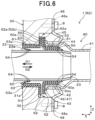
- FIG. 6 shows a cross-sectional view of a second region in FIG. 1 ;
- FIG. 7 shows a schematic diagram how a connector and a sealing member are assembled
- FIG. 8 shows a perspective view of the connector of the power conversion device according to the first embodiment as viewed from a pipe portion
- FIG. 9 shows a perspective view of the connector of FIG. 8 as viewed from the backside of a flange portion
- FIG. 10 shows a flowchart of a crimping operation of the connector of FIG. 8 ;
- FIG. 11 shows a perspective view of the pipe portion and the flange portion, which are temporarily assembled in the first step of FIG. 10 ;
- FIG. 12 shows a perspective view of a crimping jig used in the joining operation of FIG. 10 ;
- FIG. 13 shows a schematic view illustrating the manner of the second step in FIG. 10 ;
- FIG. 14 shows a schematic view illustrating the manner of the third step in FIG. 10 ;
- FIG. 15 shows a schematic view illustrating the manner of the fourth step in FIG. 10 ;
- FIG. 16 shows a perspective view of a connector of a power conversion device according to a second embodiment corresponding to FIG. 9 ;
- FIG. 17 shows an exploded perspective view of the connector of FIG. 16 .
- each connector is located between one of the refrigerant flow pipes of the cooling device and an external pipe.
- Each connector includes a tubular portion, which communicates with the associated refrigerant flow pipe, and a flange portion, which projects radially outward from the tubular portion, and is configured as an integral part formed of a plastic material.
- the shape of the connector needs to be changed accordingly.
- various kinds of connectors corresponding to the shapes of the available external pipes need to be prepared to improve the versatility in connecting to external pipes having a variety of shapes.
- the changes in the shape of the connector affects the entire connector, the costs required for producing the connector may be undesirably increased.
- the present disclosure is intended to provide a power conversion device that includes a highly versatile and low-cost connector located between a refrigerant flow pipe of a cooling device for semiconductor modules and an external pipe.
- One aspect of the present disclosure provides a power conversion device that includes a semiconductor module, a cooling device, a case, a connector, and a sealing member.
- the semiconductor module includes a switching element.
- the cooling device includes a heat exchanger capable of exchanging heat with the semiconductor module, an inlet pipe that introduces a refrigerant to the heat exchanger, and a discharge pipe that discharges the refrigerant from the heat exchanger.
- the case accommodates the semiconductor module and the cooling device.
- the connector is connected to a refrigerant flow pipe, which is at least one of the inlet pipe and the discharge pipe of the cooling device on an outside of the case.
- the sealing member seals between the refrigerant flow pipe and the connector.
- the connector includes a pipe portion, which communicates with the refrigerant flow pipe, and a flange portion, which is secured to the case.
- the pipe portion and the flange portion are joined to each other with the pipe portion located in an insertion hole of the flange portion.
- the connector includes an axial direction restricting section that restricts the pipe portion and the flange portion from relatively moving in an axial direction of the pipe portion.
- the axial direction restricting section includes at least one projection that projects radially outward on the pipe portion, and the at least one projection is located adjacent to an opening edge portion of the insertion hole of the flange portion.
- a power conversion device that includes a semiconductor module, a cooling device, a case, a connector, and a sealing member.
- the semiconductor module includes a switching element.
- the cooling device includes a heat exchanger capable of exchanging heat with the semiconductor module, an inlet pipe that introduces a refrigerant to the heat exchanger, and a discharge pipe that discharges the refrigerant from the heat exchanger.
- the case accommodates the semiconductor module and the cooling device.
- the connector is connected to a refrigerant flow pipe, which is at least one of the inlet pipe and the discharge pipe of the cooling device on an outside of the case.
- the sealing member seals between the refrigerant flow pipe and the connector.
- the connector includes a pipe portion, which communicates with the refrigerant flow pipe, and a flange portion, which is secured to the case.
- the pipe portion and the flange portion are joined to each other with the pipe portion located in an insertion hole of the flange portion.
- the pipe portion and the flange portion of the connector are both made of a metal material and are joined to each other by a deformation process.
- the power conversion device 1 includes an inverter circuit 70 , which is a power conversion circuit that converts DC power supplied from a DC power supply B 1 to AC power.
- the inverter circuit 70 the semiconductor modules 10 are electrically connected to the control substrate 3 , and the control substrate 3 controls the switching operation (ON/OFF operation) of the semiconductor modules 10 .
- the control substrate 3 is secured to the case 30 as shown in FIG. 2 .
- the capacitor 2 A is for removing a noise current included in the current supplied from the DC power supply B 1 and is also referred to as a filter capacitor. Like the capacitor 2 described above, the capacitor 2 A is configured as a capacitor including a film capacitor element.
- the reactor 4 is a passive element that uses an inductor.
- the DC-DC converter 5 is connected to the DC power supply B 1 .
- the DC-DC converter 5 is used to lower the voltage of the DC power supply B 1 and charge the auxiliary battery B 2 that has a lower voltage than the DC power supply B 1 .
- the auxiliary battery B 2 is used as a power supply for a variety of devices mounted on a vehicle.
- the inlet pipe 22 which is the refrigerant flow pipe, is inserted in a through-hole 31 formed through the case 30 so that the distal end section projects outside the case 30 .
- the inlet pipe 22 is configured to be connected to one of the connectors 40 on the outside of the case 30 (refer to the first region R 1 in FIG. 1 ).
- the first sealing member 50 seals between the inlet pipe 22 and the associated connector 40 .
- the connector 40 includes a tubular pipe portion 41 , which communicates with the inlet pipe 22 , and a flange portion 45 , which is secured to the case 30 with fastening members 8 .
- the pipe portion 41 and the flange portion 45 are both formed of a metal material and are joined as one unit.
- the connector 40 is made of a metal material.
- the metal material of the connector 40 may typically be a stainless-steel material that has high corrosion resistance against the refrigerant.
- the pipe portion 41 includes an inner tube 42 , which has an inner diameter greater than the outer diameter of the inlet pipe 22 , a disk-like projection 43 that projects radially outward from the inner tube 42 , and a projection 44 that projects radially outward from the position on the opposite side of the inner tube 42 from the projection 43 .
- the distal end section of the inlet pipe 22 is inserted inside the inner tube 42 of the pipe portion 41 .
- One of the external pipes E (refer to FIG. 1 ) that is to communicate with the inlet pipe 22 is connected to the pipe portion 41 .
- the pipe portion 41 virtually forms the connector 40 .
- the flange portion 45 includes a cylindrical outer tube 46 , which is located on the outer periphery of the inner tube 42 of the pipe portion 41 , and a disk-like flange portion 48 , which extends radially outward from the outer tube 46 .
- the space in the outer tube 46 forms an insertion hole 47 in which the inner tube 42 of the pipe portion 41 is inserted.
- the outer tube 46 is an opening edge portion of the insertion hole 47 .
- the flange portion 48 includes mounting holes 48 a in which the shafts of the fastening members 8 are inserted.
- the outer tube 46 is sandwiched between the projection 43 and the projection 44 , which are both formed on the pipe portion 41 adjacent to the outer tube 46 and project radially outward.
- the projection 43 and the projection 44 configure an axial direction restricting section, which restricts the pipe portion 41 and the flange portion 45 from relatively moving in the first direction X, which is the axial direction of the pipe portion 41 .
- the first sealing member 50 includes a connector-side tubular portion, which is a tubular portion 51 , a disk-like flange portion 52 , which extends radially outward from the tubular portion 51 , a first watertight seal projection, which is a projection 53 , and second watertight seal projections, which are projections 54 .
- the first sealing member 50 is simply referred to as the “sealing member 50 ”.
- the sealing member 50 includes a metal core material 50 a , which forms a frame portion, and a plastic portion, which covers around the core material 50 a with a plastic material.
- the projections 53 and 54 of the sealing member 50 are formed of the plastic portion around the core material 50 a.
- the sealing member 50 is inserted in the connector 40 in an insertion direction D 2 and, in this state, the sealing member 50 is mounted on the case 30 together with the connector 40 .
- the tubular portion 51 of the sealing member 50 is located between an inner peripheral surface 40 a of the connector 40 and an outer peripheral surface 22 a of the inlet pipe 22 .
- the flange portion 52 is located such that the projection 43 of the pipe portion 41 is sandwiched between the flange portion 52 and the flange portion 45 in the first direction X.
- the projection 53 is formed as an annular projection that projects radially outward in an annular shape from the tubular portion 51 toward the inner peripheral surface 40 a of the connector 40 .
- the cross-sectional shape of the projection 53 on the plane determined by the first direction X and the third direction Z is substantially a trapezoid the width of which in the first direction X gradually decreases radially outward.
- the projection 53 forms a trapezoidal lip seal structure.
- the projection 53 abuts against the inner peripheral surface 40 a of the connector 40 . At this time, the projection 53 is compressed by the inner peripheral surface 40 a of the connector 40 and elastically deforms, so that watertight sealing performance is exerted.
- the projections 54 are formed as annular projections that project radially inward in an annular shape from the tubular portion 51 toward the outer peripheral surface 22 a of the inlet pipe 22 .
- the projections 54 are generally provided on an arm portion that extends rightward in FIG. 5 from the section corresponding to the right distal end section of the core material 50 a .
- the cross-sectional shape of the arm portion on the plane determined by the first direction X and the third direction Z is shaped such that two annular projections 54 are spaced apart in the first direction X.
- the two projections 54 form a double lip seal structure.
- the projections 54 When the two projections 54 abut against the outer peripheral surface 22 a of the inlet pipe 22 , the projections 54 are compressed by the outer peripheral surface 22 a of the inlet pipe 22 and elastically deform, so that watertight sealing performance is exerted. Since the flexible plastic arm portion is long, the arm portion elastically deforms in accordance with the eccentricity of the inlet pipe 22 , so that the projections 54 can maintain high watertight sealing performance.
- the projections 54 shaped as above have a good ability to deform in accordance with the eccentricity of the inlet pipe 22 .
- the projection 53 and the projections 54 are all shaped as if the projecting portion is extended annularly in the circumferential direction and extend on the plane determined by the second direction Y and the third direction Z.
- one projection 53 is located on the outer surface of the tubular portion 51
- two projections 54 are located on the inner surface of the tubular portion 51 with a gap in the first direction X.
- the number, position, and shape of the projection 53 and the projections 54 are not limited to those mentioned above and can be changed as required. That is, the number of the projections 53 may be the same as the number of the projections 54 , or the number of the projections 53 may differ from the number of the projections 54 .
- the cross-sectional shape of the projection 53 may be a rectangle the width of which in the first direction X is generally constant. To improve the sealing performance, the number of the projections 53 and 54 is preferably increased.
- the second sealing member 60 is provided at a position closer to the cooling pipes 21 of the cooling device 20 than the sealing member 50 in the first direction X to seal between the through-hole 31 of the case 30 and the inlet pipe 22 .
- the second sealing member 60 is configured as a separate member from the sealing member 50 .
- the second sealing member 60 includes a case-side tubular portion, which is a tubular portion 61 , a disk-like flange portion 62 , which extends radially outward from the tubular portion 61 , a first airtight seal projection, which is a projection 63 , and second airtight seal projections, which are projections 64 .
- the second sealing member 60 is simply referred to as the “sealing member 60 ”.
- the sealing member 60 includes, like the sealing member 50 , a metal core material 60 a , which forms a frame portion, and a plastic portion, which covers around the core material 60 a with a plastic material.
- the projections 63 and 64 of the sealing member 60 are formed of the plastic portion around the core material 60 a.
- the sealing member 60 is mounted on the case 30 by being inserted in the case 30 in an insertion direction D 1 .
- the tubular portion 61 of the sealing member 60 is located between an inner peripheral surface 31 a of the through-hole 31 of the case 30 and the outer peripheral surface 22 a of the inlet pipe 22 .
- the flange portion 62 is located to abut against an end surface 32 of the case 30 in the first direction X from the outside.
- the insertion direction D 1 of the sealing member 60 corresponds to a removing direction D 1 of the sealing member 50 .
- a removing direction D 2 of the sealing member 60 corresponds to the insertion direction D 2 of the sealing member 50 .
- the flange portion 62 of the sealing member 60 is provided to overlap the flange portion 52 of the sealing member 50 in the removing direction D 1 of the sealing member 50 .
- the dimension of the flange portion 62 is preferably set to overlap the flange portion 52 of the sealing member 50 in the removing direction D 1 .
- the flange portion 62 serves as a first sealing member restricting section, which restricts the movement of the sealing member 50 in the removing direction D 1 . As a result, the sealing member 50 becomes unlikely to fall out, and the watertight sealing performance of the sealing member 50 is maintained.
- the projection 63 is formed as an annular projection that projects radially outward in an annular shape from the tubular portion 61 toward the inner peripheral surface 31 a of the through-hole 31 of the case 30 .
- the cross-sectional shape of the projection 63 on the plane determined by the first direction X and the third direction Z is substantially a trapezoid the width of which in the first direction X gradually decreases radially outward.
- the projection 63 forms a trapezoidal lip seal structure.
- the projection 63 abuts against the inner peripheral surface 31 a of the through-hole 31 . At this time, the projection 63 is compressed by the inner peripheral surface 31 a of the through-hole 31 and elastically deforms, so that airtight sealing performance is exerted.
- the locking portion 33 of the case 30 is chamfered where the corner is cut at an angle.
- the locking portion 33 may be provided annularly in the circumferential direction or may be provided partially in the circumferential direction.
- the projections 64 are formed as annular projections that project radially inward in an annular shape from the tubular portion 61 toward the outer peripheral surface 22 a of the inlet pipe 22 .
- the projections 64 are generally provided on an arm portion that extends rightward in FIG. 5 from the section corresponding to the left distal end section of the core material 60 a .
- the cross-sectional shape of the arm portion on the plane determined by the first direction X and the third direction Z is shaped such that two annular projections 64 are spaced apart in the first direction X.
- the two projections 64 form a double lip seal structure.
- the projections 64 When the two projections 64 abut against the outer peripheral surface 22 a of the inlet pipe 22 , the projections 64 are compressed by the outer peripheral surface 22 a of the inlet pipe 22 and elastically deform, so that airtight sealing performance is exerted. Since the flexible plastic arm portion is long, the arm portion elastically deforms in accordance with the eccentricity of the inlet pipe 22 , so that the projections 64 can maintain high airtight sealing performance.
- the projections 64 shaped as above have a good ability to deform in accordance with the eccentricity of the inlet pipe 22 .
- the projection 63 and the projections 64 are all shaped as if the projecting portion is extended annularly in the circumferential direction and extend on the plane determined by the second direction Y and the third direction Z.
- one projection 63 is located on the outer surface of the tubular portion 61
- two projections 64 are located on the inner surface of the tubular portion 61 with a gap in the first direction X. Additionally, the two projections 63 overlap the two projections 64 in the third direction Z, respectively.
- the number, position, and shape of the projection 63 and the projections 64 are not limited to those mentioned above and can be changed as required. That is, the number of the projection 63 may be the same as the number of the projection 64 , or the number of the projection 63 may differ from the number of the projection 64 .
- the cross-sectional shape of the projection 63 may be a rectangle the width of which in the first direction X is generally constant. To improve the sealing performance, the number of the projections 63 and 64 is preferably increased.
- the number of the projections 54 may be greater than the number of the projection 53 on the sealing member 50 , or the number of the projections 64 may be greater than the number of the projection 63 on the sealing member 60 .
- a gap 55 in the first direction X is formed between a first opposing surface 52 a of the flange portion 52 of the sealing member 50 and a second opposing surface 62 a of the flange portion 62 of the sealing member 60 .
- the first opposing surface 52 a and the second opposing surface 62 a face each other in the first direction X.
- the gap 55 forms a refrigerant discharging passage that connects the space between the sealing member 50 and the outer peripheral surface 22 a of the inlet pipe 22 to the outside of the case 30 .
- the gap 55 functions to discharge the refrigerant to the outside of the case 30 when the refrigerant flows into the space on the outer peripheral surface 22 a of the inlet pipe 22 .
- the gap 55 prevents the refrigerant from flowing to the inside of the case 30 .
- the discharge pipe 23 which is the refrigerant flow pipe, is inserted in the through-hole 31 formed through the case 30 , and the distal end section projects to the outside of the case 30 .
- the discharge pipe 23 is configured to be connected to the connector 40 that is the same as the one used in the case of the inlet pipe 22 on the outside of the case 30 (refer to the second region R 2 in FIG. 1 ).
- the sealing member 50 which is the same as the one used in the case of the inlet pipe 22 , seals between the discharge pipe 23 and the connector 40 .
- the connector 40 is configured such that the tubular pipe portion 41 communicates with the discharge pipe 23 .
- the inner tube 42 of the pipe portion 41 has an inner diameter greater than the outer diameter of the discharge pipe 23 .
- the distal end section of the discharge pipe 23 is inserted inside the inner tube 42 .
- the other one of the external pipes E (not shown, refer to FIG. 1 ) that is to communicate with the discharge pipe 23 is connected to the pipe portion 41 .
- the sealing member 50 and the sealing member 60 are the same as those used in the case of the inlet pipe 22 , and only the differences will be described.
- the tubular portion 51 of the sealing member 50 is located between the inner peripheral surface 40 a of the connector 40 and an outer peripheral surface 23 a of the discharge pipe 23 .
- the projection 53 of the sealing member 50 projects radially outward from the tubular portion 51 toward the inner peripheral surface 40 a of the connector 40
- the projections 54 of the sealing member 50 project radially inward from the tubular portion 51 toward the outer peripheral surface 23 a of the discharge pipe 23 .
- the tubular portion 61 of the sealing member 60 is located between the inner peripheral surface 31 a of the through-hole 31 of the case 30 and the outer peripheral surface 23 a of the discharge pipe 23 .
- the projection 63 of the sealing member 60 projects radially outward from the tubular portion 61 toward the inner peripheral surface 31 a of the through-hole 31 of the case 30
- the projections 64 of the sealing member 60 project radially inward from the tubular portion 61 toward the outer peripheral surface 23 a of the inlet pipe 23 .
- the sealing member 50 is previously mounted on the connector 40
- the sealing member 60 is previously mounted on the case 30 .
- the sealing member 50 is mounted on the connector 40 by pushing the tubular portion 51 that has been inserted in the connector 40 in the insertion direction D 2 until the flange portion 52 abuts against the connector 40 . At this time, the projection 53 of the sealing member 50 slides along the inner peripheral surface 40 a of the connector 40 .
- the sealing member 60 is fitted to the inlet pipe 22 , and then the tubular portion 61 is inserted in the through-hole 31 of the case 30 .
- the tubular portion 61 that has been inserted in the through-hole 31 is pushed in the insertion direction D 1 until the flange portion 62 abuts against the case 30 .
- the sealing member 60 is mounted on the case 30 .
- the projection 63 of the sealing member 60 slides along the inner peripheral surface 31 a of the through-hole 31 of the case 30
- the projections 64 of the sealing member 60 slide along the outer peripheral surface 22 a of the inlet pipe 22 .
- the locking portion 33 functions as a second sealing member restricting section, which restricts the movement of the sealing member 60 in the removing direction D 2 . Since the locking portion 33 is chamfered, it is advantageous in preventing damage on the sealing member 60 .
- the case 30 and the connector 40 are brought close to each other, and the inlet pipe 22 is inserted in the tubular portion 51 of the sealing member 50 .
- the projections 54 of the sealing member 50 slide along the outer peripheral surface 22 a of the inlet pipe 22 .
- the connector 40 is then fastened to the case 30 with the fastening members 8 inserted in the mounting holes 48 a of the flange portion 45 (refer to FIG. 5 ).
- the connector 40 includes the pipe portion 41 and the flange portion 45 joined to each other in a state in which the pipe portion 41 is inserted in the insertion hole 47 of the flange portion 45 .
- the projection 43 of the pipe portion 41 is configured such that the annular end face extending in the circumferential direction forms a surface with projections and recesses (surface with steps) in the first direction X.
- the surface with projections and recesses is formed by alternately placing engaging projections 43 a and engaging recesses 43 b in the circumferential direction with respect to the outer tube 46 of the flange portion 45 .
- the outer tube 46 of the flange portion 45 is configured in such a manner that the annular end face extending in the circumferential direction forms a surface with projections and recesses (surface with steps) in the first direction X.
- the surface with projections and recesses is formed by alternately placing engaging projections 46 a and engaging recesses 46 b in the circumferential direction with respect to the projection 43 of the pipe portion 41 .
- the connector 40 has a fitting structure in which the engaging projections 43 a of the pipe portion 41 are fitted in the engaging recesses 46 b of the flange portion 45 , and the engaging projections 46 a of the flange portion 45 are fitted in the engaging recesses 43 b of the pipe portion 41 .
- the fitting structure functions as a circumferential direction restricting section, which restricts the pipe portion 41 and the flange portion 45 from relatively moving in the circumferential direction of the pipe portion.
- the fitting structure includes the engaging projections 43 a and the engaging recesses 43 b , which are a first engaging portion on the pipe portion 41 , and the engaging recesses 46 b and the engaging projections 46 a , which are a second engaging portion on the flange portion 45 engaged with the engaging projections 43 a and the engaging recesses 43 b of the pipe portion 41 .
- the number of the engaging projections 43 a , the engaging recesses 43 b , the engaging projections 46 a , and the engaging recesses 46 b of the fitting structure can be changed as required.
- the above-mentioned fitting structure of the connector 40 is formed by crimping, which is one of deformation processes.
- the crimping will be described with reference to FIGS. 10 to 15 .
- the crimping of the connector 40 is achieved by sequentially executing the operations from the first step S 101 to the fifth step S 105 .
- one or more steps may be added to the flowchart, each step may be divided into multiple steps, or multiple steps may be combined as required.
- the first step S 101 of FIG. 10 is a step for temporarily assembling a pipe portion 41 A and a flange portion 45 A before being crimped.
- the outer tube 46 of the flange portion 45 A includes the engaging projections 46 a and the engaging recesses 46 b , which are alternately formed in the circumferential direction in advance.
- the pipe portion 41 A is inserted in the insertion hole 47 , which is the space inside the outer tube 46 (refer to FIG. 11 ).
- the projection 44 of the pipe portion 41 A (refer to FIGS.
- a crimping jig 80 is used in crimping the pipe portion 41 A and the flange portion 45 A.
- the crimping jig 80 includes a deformation preventing guide 81 , a first punch 82 , a second punch 83 , and a load receiver 84 (refer to FIG. 13 ).
- the deformation preventing guide 81 prevents the deformation of the inner tube 42 of the pipe portion 41 A during crimping.
- the deformation preventing guide 81 is configured as a columnar member having an outer diameter that is the same as the inner diameter of the inner tube 42 of the pipe portion 41 A.
- the first punch 82 performs the initial stage process of pressing the end 42 a of the inner tube 42 of the pipe portion 41 A to deform the end 42 a into the projection 43 .
- the first punch 82 is configured as a circular truncated cone member including a tapered pressing surface 82 a.
- the second punch 83 is used after using the first punch 82 .
- the second punch 83 performs the final stage process of pressing the end 42 a of the inner tube 42 of the pipe portion 41 A to deform the end 42 a into the projection 43 .
- the second punch 83 includes a pressing surface that presses the end 42 a of the inner tube 42 of the pipe portion 41 A.
- the pressing surface is circular in a planar view.
- the pressing surface is formed of projecting surfaces 83 a and recessed surfaces 83 b that are alternately arranged in the circumferential direction.
- the load receiver 84 is for receiving the pressing load applied from the first punch 82 and the second punch 83 .
- the second step S 102 of FIG. 10 is a step for inserting, after the first step S 101 , the deformation preventing guide 81 into the inner tube 42 of the pipe portion 41 A.
- the deformation preventing guide 81 is inserted in the inner tube 42 of the pipe portion 41 A as shown in FIG. 13 .
- the third step S 103 of FIG. 10 is a step for performing the process with the first punch 82 after the second step S 102 .
- the end 42 a of the inner tube 42 of the pipe portion 41 A is pressed using the pressing surface 82 a of the first punch 82 and is widened radially outward.
- the fourth step S 104 of FIG. 10 is a step for performing the process with the second punch 83 subsequent to the third step S 103 .
- the end 42 a of the inner tube 42 of the pipe portion 41 A is pressed using the pressing surface of the second punch 83 and is further widened radially outward.
- the projecting surfaces 83 a and the recessed surfaces 83 b which form the pressing surface of the second punch 83 , plastically deform the end 42 a of the inner tube 42 of the pipe portion 41 A together with the outer tube 46 of the flange portion 45 A.
- the projecting surfaces 83 a of the second punch 83 form the engaging projections 43 a of the projection 43 on the end 42 a of the inner tube 42 , and the engaging projections 43 a are fitted to the engaging recesses 46 b of the outer tube 46 .
- the recessed surfaces 83 b of the second punch 83 presses the engaging recesses 43 b of the projection 43 .
- the engaging recesses 43 b are fitted to the engaging projections 46 a of the outer tube 46 .
- the connector 40 is formed in which the pipe portion 41 and the flange portion 45 are joined to each other by crimping.
- the fifth step S 105 of FIG. 10 is a step for removing the deformation preventing guide 81 from the connector 40 after the fourth step S 104 .
- the cooling pipes 21 which are the heat exchanger of the cooling device 20 , are capable of exchanging heat with the semiconductor modules 10 , which include the switching elements 11 .
- the connectors 40 are connected to the inlet pipe 22 and the discharge pipe 23 of the cooling device 20 outside the case 30 . Each connector 40 is located between the inlet pipe 22 or the discharge pipe 23 of the cooling device 20 and the external pipe E. When the connector 40 is connected to the inlet pipe 22 or the discharge pipe 23 , the sealing member 50 seals between the inlet pipe 22 or the discharge pipe 23 and the connector 40 .
- the connector 40 is configured such that the pipe portion 41 and the flange portion 45 are joined to each other by crimping in a state in which the pipe portion 41 , which is a separate member from the flange portion 45 , is inserted in the insertion hole 47 of the flange portion 45 .
- the flange portion 45 is used in common by the external pipes E having different shapes, the versatility in connecting to the external pipes E of a variety of shapes is improved by changing only the shape of the pipe portion 41 , which is a separate member from the flange portion 45 .
- the changing of the shape of the pipe portion 41 includes employing a bent pipe that is bent at a given angle or an odd-shaped pipe formed by connecting pipes with different shapes instead of the straight pipe extending linearly as shown in FIG. 8 .
- the above-described first embodiment 1 provides the power conversion device 1 that includes the highly versatile and low-cost connector 40 located between the inlet pipe 22 or the discharge pipe 23 , which are the refrigerant flow pipe of the cooling device 20 for the semiconductor modules 10 , and the external pipe E.
- the projection 43 and the projection 44 of the pipe portion 41 sandwich the outer tube 46 of the flange portion 45 , so that the pipe portion 41 and the flange portion 45 are restricted from relatively moving in the first direction X, which is the axial direction.
- the engaging projections 43 a and the engaging recesses 43 b provided on the projection 43 of the pipe portion 41 are fitted to the engaging projections 46 a and the engaging recesses 46 b provided on the outer tube 46 of the flange portion 45 , so that the pipe portion 41 and the flange portion 45 are restricted from relatively moving in the circumferential direction.
- the projection 43 of the pipe portion 41 functions to restrict the relative movement of the pipe portion 41 and the flange portion 45 in the axial direction and to restrict the relative movement of the pipe portion 41 and the flange portion 45 in the circumferential direction.
- the pipe portion 41 and the flange portion 45 are joined as one unit by crimping. This reduces the cost that is otherwise required for the molds in molding and allows the pipe portion 41 and the flange portion 45 to be joined at a low cost.
- the axial direction restricting section for restricting the relative movement of the pipe portion 41 and the flange portion 45 in the axial direction may be formed on one of the projection 43 and the projection 44 or may be formed by a section other than the projection 43 and the projection 44 .
- a power conversion device 101 according to a second embodiment differs from that of the first embodiment in the structure of a connector 140 .
- the projection 43 of the pipe portion 41 A is constituted by engaging pieces 43 c that project from the end 42 a of the inner tube 42 in the first direction X and are arranged in the circumferential direction at substantially equal intervals.
- the engaging pieces 43 c are bent radially outward using a bending process, which is a deformation process, so that the pipe portion 41 A turns into the pipe portion 41 (refer to FIG. 16 ).
- engaging grooves 46 c are provided at substantially equal intervals in the circumferential direction on the annular end face of the outer tube 46 of the flange portion 45 .
- the engaging grooves 46 c are formed by a deformation process such as pressing, notching, and bending.
- the engaging pieces 43 c of the pipe portion 41 that are bent radially outward are fitted to the engaging grooves 46 c of the flange portion 45 , respectively, so that the connector 140 is formed.
- the connector 140 has the fitting structure in which the engaging pieces 43 c of the pipe portion 41 are fitted to the engaging grooves 46 c of the flange portion 45 .
- the fitting structure functions as the circumferential direction restricting section, which restricts the pipe portion 41 and the flange portion 45 from relatively moving in the circumferential direction of the pipe portion.
- the number of the engaging pieces 43 c and the engaging grooves 46 c may be changed as required.
- the pipe portion 41 and the flange portion 45 are joined as one unit by the deformation process other than crimping.
- the above-described embodiments exemplify the case in which the connector 40 , 140 is connected to each of the inlet pipe 22 and the discharge pipe 23 of the cooling device 20 .
- the connector 40 , 140 may be connected to one of the inlet pipe 22 and the discharge pipe 23 , and a connector having a different structure from the connector 40 , 140 may be connected to the other one of the inlet pipe 22 and the discharge pipe 23 .
- the above-described embodiments exemplify the case in which the connector 40 , 140 made of a metal material is employed. Instead, the connector 40 , 140 made of a material other than the metal material such as a plastic material may be employed.
- the above-described embodiments exemplify the stack-type cooling device 20 , which cools the semiconductor modules 10 .
- the structure of the cooling device is not limited to the stack type, and a cooling device having a different structure may be employed as required as long as the cooling device 20 includes the heat exchanger that is capable of exchanging heat with the semiconductor modules, the inlet pipe that introduces a refrigerant to the heat exchanger, and the discharge pipe that discharges the refrigerant from the heat exchanger.
Landscapes
- Engineering & Computer Science (AREA)
- Microelectronics & Electronic Packaging (AREA)
- Physics & Mathematics (AREA)
- Power Engineering (AREA)
- Condensed Matter Physics & Semiconductors (AREA)
- General Physics & Mathematics (AREA)
- Computer Hardware Design (AREA)
- Thermal Sciences (AREA)
- Inverter Devices (AREA)
- Cooling Or The Like Of Semiconductors Or Solid State Devices (AREA)
Applications Claiming Priority (3)
| Application Number | Priority Date | Filing Date | Title |
|---|---|---|---|
| JP2019-086339 | 2019-04-26 | ||
| JP2019086339A JP7003967B2 (ja) | 2019-04-26 | 2019-04-26 | 電力変換装置 |
| PCT/JP2020/015764 WO2020217984A1 (ja) | 2019-04-26 | 2020-04-08 | 電力変換装置 |
Related Parent Applications (1)
| Application Number | Title | Priority Date | Filing Date |
|---|---|---|---|
| PCT/JP2020/015764 Continuation WO2020217984A1 (ja) | 2019-04-26 | 2020-04-08 | 電力変換装置 |
Publications (2)
| Publication Number | Publication Date |
|---|---|
| US20220046831A1 US20220046831A1 (en) | 2022-02-10 |
| US12178023B2 true US12178023B2 (en) | 2024-12-24 |
Family
ID=72941891
Family Applications (1)
| Application Number | Title | Priority Date | Filing Date |
|---|---|---|---|
| US17/510,771 Active 2041-01-14 US12178023B2 (en) | 2019-04-26 | 2021-10-26 | Power conversion device |
Country Status (3)
| Country | Link |
|---|---|
| US (1) | US12178023B2 (enExample) |
| JP (1) | JP7003967B2 (enExample) |
| WO (1) | WO2020217984A1 (enExample) |
Families Citing this family (2)
| Publication number | Priority date | Publication date | Assignee | Title |
|---|---|---|---|---|
| JP7427916B2 (ja) * | 2019-10-31 | 2024-02-06 | セイコーエプソン株式会社 | 流路部材、流路ユニット、および、液体噴射装置 |
| DE102021210153A1 (de) * | 2021-09-14 | 2023-03-16 | Robert Bosch Gesellschaft mit beschränkter Haftung | Elektronikanordnung |
Citations (12)
| Publication number | Priority date | Publication date | Assignee | Title |
|---|---|---|---|---|
| US5797602A (en) * | 1996-10-10 | 1998-08-25 | Pac-Seal Inc. International | Mechanical seal for water pump of heavy duty vehicle |
| US20040124289A1 (en) * | 2002-12-09 | 2004-07-01 | Pacific Industrial Co., Ltd. | Nozzle cap for sealing nozzle particularly used to charge with high pressurized fluid |
| US20070039717A1 (en) * | 2005-08-19 | 2007-02-22 | Denso Corporation | Heat exchanger unit and method of manufacturing the same |
| US20100212622A1 (en) * | 2009-02-24 | 2010-08-26 | Cleeves Engines Inc. | Sleeve valve assembly |
| JP2014009761A (ja) | 2012-06-29 | 2014-01-20 | Sekisui Chem Co Ltd | フランジ付管体 |
| US20140367964A1 (en) | 2012-02-07 | 2014-12-18 | Kazumi Kobayashi | Flange Joint Connection Structure |
| JP2015053763A (ja) | 2013-09-05 | 2015-03-19 | 株式会社デンソー | 電力変換装置 |
| US20150152987A1 (en) * | 2013-12-04 | 2015-06-04 | Toyota Jidosha Kabushiki Kaisha | Connecting structure for refrigerant pipe and inverter including connecting structure |
| US20160374235A1 (en) * | 2013-07-01 | 2016-12-22 | Toyota Jidosha Kabushiki Kaisha | Inverter case |
| US20170335705A1 (en) * | 2016-05-23 | 2017-11-23 | United Technologies Corporation | Engine air sealing by seals in series |
| US20190264984A1 (en) * | 2016-11-21 | 2019-08-29 | Denso Corporation | Stacked heat exchanger |
| US20200308972A1 (en) * | 2019-03-27 | 2020-10-01 | United Technologies Corporation | Seal support feature for brush seals |
-
2019
- 2019-04-26 JP JP2019086339A patent/JP7003967B2/ja active Active
-
2020
- 2020-04-08 WO PCT/JP2020/015764 patent/WO2020217984A1/ja not_active Ceased
-
2021
- 2021-10-26 US US17/510,771 patent/US12178023B2/en active Active
Patent Citations (12)
| Publication number | Priority date | Publication date | Assignee | Title |
|---|---|---|---|---|
| US5797602A (en) * | 1996-10-10 | 1998-08-25 | Pac-Seal Inc. International | Mechanical seal for water pump of heavy duty vehicle |
| US20040124289A1 (en) * | 2002-12-09 | 2004-07-01 | Pacific Industrial Co., Ltd. | Nozzle cap for sealing nozzle particularly used to charge with high pressurized fluid |
| US20070039717A1 (en) * | 2005-08-19 | 2007-02-22 | Denso Corporation | Heat exchanger unit and method of manufacturing the same |
| US20100212622A1 (en) * | 2009-02-24 | 2010-08-26 | Cleeves Engines Inc. | Sleeve valve assembly |
| US20140367964A1 (en) | 2012-02-07 | 2014-12-18 | Kazumi Kobayashi | Flange Joint Connection Structure |
| JP2014009761A (ja) | 2012-06-29 | 2014-01-20 | Sekisui Chem Co Ltd | フランジ付管体 |
| US20160374235A1 (en) * | 2013-07-01 | 2016-12-22 | Toyota Jidosha Kabushiki Kaisha | Inverter case |
| JP2015053763A (ja) | 2013-09-05 | 2015-03-19 | 株式会社デンソー | 電力変換装置 |
| US20150152987A1 (en) * | 2013-12-04 | 2015-06-04 | Toyota Jidosha Kabushiki Kaisha | Connecting structure for refrigerant pipe and inverter including connecting structure |
| US20170335705A1 (en) * | 2016-05-23 | 2017-11-23 | United Technologies Corporation | Engine air sealing by seals in series |
| US20190264984A1 (en) * | 2016-11-21 | 2019-08-29 | Denso Corporation | Stacked heat exchanger |
| US20200308972A1 (en) * | 2019-03-27 | 2020-10-01 | United Technologies Corporation | Seal support feature for brush seals |
Non-Patent Citations (1)
| Title |
|---|
| Jul. 14, 2020 International Search Report issued in International Application No. PCT/JP2020/015764. |
Also Published As
| Publication number | Publication date |
|---|---|
| JP2020182363A (ja) | 2020-11-05 |
| WO2020217984A1 (ja) | 2020-10-29 |
| US20220046831A1 (en) | 2022-02-10 |
| JP7003967B2 (ja) | 2022-01-21 |
Similar Documents
| Publication | Publication Date | Title |
|---|---|---|
| US9936616B2 (en) | Electric power convertor | |
| JP5012389B2 (ja) | 電力変換装置 | |
| CN102170219B (zh) | 能量转换装置 | |
| JP4924750B2 (ja) | 電力変換装置 | |
| US8958225B2 (en) | Electric power converter | |
| US12178023B2 (en) | Power conversion device | |
| US8440918B2 (en) | Assembly of case and electronic components and combination of the assembly and external connectors | |
| JP2014003136A (ja) | 電力変換装置 | |
| US20200176168A1 (en) | Reactor cooling structure | |
| US9807915B2 (en) | Heat exchanger for cooling electric element | |
| JP2010200478A (ja) | 電力変換装置 | |
| US10147667B2 (en) | Cooler module, and method for manufacturing cooler module | |
| CN107809167B (zh) | 带半导体模块和被加压构件加压的电子部件的电力转换装置 | |
| CN1697264A (zh) | 具有接头部分的壳体元件 | |
| US11805628B2 (en) | Power conversion device | |
| JP6219780B2 (ja) | 電子機器及び電子機器に備えられる管継手 | |
| KR20180112983A (ko) | 전기소자 쿨링모듈 | |
| JP5333274B2 (ja) | 電力変換装置 | |
| JP5423459B2 (ja) | 電力変換装置 | |
| JP5287160B2 (ja) | バスバー、及びこれを内蔵した電力変換装置 | |
| JP2018182075A (ja) | コンデンサモジュール | |
| CN117294217A (zh) | 一种电机控制器、动力总成及车辆 | |
| CN116458272A (zh) | 壳体和电气装置 | |
| CN222785384U (zh) | 密封箱体、电池包及储能装置 | |
| CN115378281B (zh) | 一种驱动器用过滤整流器 |
Legal Events
| Date | Code | Title | Description |
|---|---|---|---|
| FEPP | Fee payment procedure |
Free format text: ENTITY STATUS SET TO UNDISCOUNTED (ORIGINAL EVENT CODE: BIG.); ENTITY STATUS OF PATENT OWNER: LARGE ENTITY |
|
| AS | Assignment |
Owner name: DENSO CORPORATION, JAPAN Free format text: ASSIGNMENT OF ASSIGNORS INTEREST;ASSIGNORS:TAKEUCHI, KAZUYA;SHIBATA, KENJI;TAKAHASHI, YOSHIHITO;SIGNING DATES FROM 20211103 TO 20211105;REEL/FRAME:058224/0630 |
|
| STPP | Information on status: patent application and granting procedure in general |
Free format text: DOCKETED NEW CASE - READY FOR EXAMINATION |
|
| STPP | Information on status: patent application and granting procedure in general |
Free format text: NON FINAL ACTION MAILED |
|
| STPP | Information on status: patent application and granting procedure in general |
Free format text: RESPONSE TO NON-FINAL OFFICE ACTION ENTERED AND FORWARDED TO EXAMINER |
|
| STPP | Information on status: patent application and granting procedure in general |
Free format text: FINAL REJECTION MAILED |
|
| STPP | Information on status: patent application and granting procedure in general |
Free format text: RESPONSE AFTER FINAL ACTION FORWARDED TO EXAMINER |
|
| STPP | Information on status: patent application and granting procedure in general |
Free format text: ADVISORY ACTION MAILED |
|
| STPP | Information on status: patent application and granting procedure in general |
Free format text: DOCKETED NEW CASE - READY FOR EXAMINATION |
|
| STPP | Information on status: patent application and granting procedure in general |
Free format text: NOTICE OF ALLOWANCE MAILED -- APPLICATION RECEIVED IN OFFICE OF PUBLICATIONS |
|
| STPP | Information on status: patent application and granting procedure in general |
Free format text: PUBLICATIONS -- ISSUE FEE PAYMENT VERIFIED |
|
| STCF | Information on status: patent grant |
Free format text: PATENTED CASE |