WO2020203161A1 - 積層体及び積層体の製造方法、並びに積層体の製造装置 - Google Patents
積層体及び積層体の製造方法、並びに積層体の製造装置 Download PDFInfo
- Publication number
- WO2020203161A1 WO2020203161A1 PCT/JP2020/010997 JP2020010997W WO2020203161A1 WO 2020203161 A1 WO2020203161 A1 WO 2020203161A1 JP 2020010997 W JP2020010997 W JP 2020010997W WO 2020203161 A1 WO2020203161 A1 WO 2020203161A1
- Authority
- WO
- WIPO (PCT)
- Prior art keywords
- hot melt
- melt adhesive
- opening
- region
- sheet
- Prior art date
- Legal status (The legal status is an assumption and is not a legal conclusion. Google has not performed a legal analysis and makes no representation as to the accuracy of the status listed.)
- Ceased
Links
Images



Classifications
-
- A—HUMAN NECESSITIES
- A61—MEDICAL OR VETERINARY SCIENCE; HYGIENE
- A61F—FILTERS IMPLANTABLE INTO BLOOD VESSELS; PROSTHESES; DEVICES PROVIDING PATENCY TO, OR PREVENTING COLLAPSING OF, TUBULAR STRUCTURES OF THE BODY, e.g. STENTS; ORTHOPAEDIC, NURSING OR CONTRACEPTIVE DEVICES; FOMENTATION; TREATMENT OR PROTECTION OF EYES OR EARS; BANDAGES, DRESSINGS OR ABSORBENT PADS; FIRST-AID KITS
- A61F13/00—Bandages or dressings; Absorbent pads
- A61F13/15—Absorbent pads, e.g. sanitary towels, swabs or tampons for external or internal application to the body; Supporting or fastening means therefor; Tampon applicators
- A61F13/15577—Apparatus or processes for manufacturing
- A61F13/15699—Forming webs by bringing together several webs, e.g. by laminating or folding several webs, with or without additional treatment of the webs
-
- A—HUMAN NECESSITIES
- A61—MEDICAL OR VETERINARY SCIENCE; HYGIENE
- A61F—FILTERS IMPLANTABLE INTO BLOOD VESSELS; PROSTHESES; DEVICES PROVIDING PATENCY TO, OR PREVENTING COLLAPSING OF, TUBULAR STRUCTURES OF THE BODY, e.g. STENTS; ORTHOPAEDIC, NURSING OR CONTRACEPTIVE DEVICES; FOMENTATION; TREATMENT OR PROTECTION OF EYES OR EARS; BANDAGES, DRESSINGS OR ABSORBENT PADS; FIRST-AID KITS
- A61F13/00—Bandages or dressings; Absorbent pads
- A61F13/15—Absorbent pads, e.g. sanitary towels, swabs or tampons for external or internal application to the body; Supporting or fastening means therefor; Tampon applicators
- A61F13/51—Absorbent pads, e.g. sanitary towels, swabs or tampons for external or internal application to the body; Supporting or fastening means therefor; Tampon applicators characterised by the outer layers of the pads
- A61F13/514—Backsheet, i.e. the impermeable cover or layer furthest from the skin
-
- A—HUMAN NECESSITIES
- A61—MEDICAL OR VETERINARY SCIENCE; HYGIENE
- A61F—FILTERS IMPLANTABLE INTO BLOOD VESSELS; PROSTHESES; DEVICES PROVIDING PATENCY TO, OR PREVENTING COLLAPSING OF, TUBULAR STRUCTURES OF THE BODY, e.g. STENTS; ORTHOPAEDIC, NURSING OR CONTRACEPTIVE DEVICES; FOMENTATION; TREATMENT OR PROTECTION OF EYES OR EARS; BANDAGES, DRESSINGS OR ABSORBENT PADS; FIRST-AID KITS
- A61F13/00—Bandages or dressings; Absorbent pads
- A61F13/15—Absorbent pads, e.g. sanitary towels, swabs or tampons for external or internal application to the body; Supporting or fastening means therefor; Tampon applicators
- A61F13/551—Packaging before or after use
- A61F13/55105—Packaging before or after use packaging of diapers
-
- A—HUMAN NECESSITIES
- A61—MEDICAL OR VETERINARY SCIENCE; HYGIENE
- A61F—FILTERS IMPLANTABLE INTO BLOOD VESSELS; PROSTHESES; DEVICES PROVIDING PATENCY TO, OR PREVENTING COLLAPSING OF, TUBULAR STRUCTURES OF THE BODY, e.g. STENTS; ORTHOPAEDIC, NURSING OR CONTRACEPTIVE DEVICES; FOMENTATION; TREATMENT OR PROTECTION OF EYES OR EARS; BANDAGES, DRESSINGS OR ABSORBENT PADS; FIRST-AID KITS
- A61F13/00—Bandages or dressings; Absorbent pads
- A61F13/15—Absorbent pads, e.g. sanitary towels, swabs or tampons for external or internal application to the body; Supporting or fastening means therefor; Tampon applicators
- A61F13/84—Accessories, not otherwise provided for, for absorbent pads
-
- B—PERFORMING OPERATIONS; TRANSPORTING
- B32—LAYERED PRODUCTS
- B32B—LAYERED PRODUCTS, i.e. PRODUCTS BUILT-UP OF STRATA OF FLAT OR NON-FLAT, e.g. CELLULAR OR HONEYCOMB, FORM
- B32B27/00—Layered products comprising a layer of synthetic resin
- B32B27/12—Layered products comprising a layer of synthetic resin next to a fibrous or filamentary layer
-
- B—PERFORMING OPERATIONS; TRANSPORTING
- B32—LAYERED PRODUCTS
- B32B—LAYERED PRODUCTS, i.e. PRODUCTS BUILT-UP OF STRATA OF FLAT OR NON-FLAT, e.g. CELLULAR OR HONEYCOMB, FORM
- B32B5/00—Layered products characterised by the non- homogeneity or physical structure, i.e. comprising a fibrous, filamentary, particulate or foam layer; Layered products characterised by having a layer differing constitutionally or physically in different parts
- B32B5/02—Layered products characterised by the non- homogeneity or physical structure, i.e. comprising a fibrous, filamentary, particulate or foam layer; Layered products characterised by having a layer differing constitutionally or physically in different parts characterised by structural features of a fibrous or filamentary layer
-
- D—TEXTILES; PAPER
- D04—BRAIDING; LACE-MAKING; KNITTING; TRIMMINGS; NON-WOVEN FABRICS
- D04H—MAKING TEXTILE FABRICS, e.g. FROM FIBRES OR FILAMENTARY MATERIAL; FABRICS MADE BY SUCH PROCESSES OR APPARATUS, e.g. FELTS, NON-WOVEN FABRICS; COTTON-WOOL; WADDING ; NON-WOVEN FABRICS FROM STAPLE FIBRES, FILAMENTS OR YARNS, BONDED WITH AT LEAST ONE WEB-LIKE MATERIAL DURING THEIR CONSOLIDATION
- D04H1/00—Non-woven fabrics formed wholly or mainly of staple fibres or like relatively short fibres
- D04H1/40—Non-woven fabrics formed wholly or mainly of staple fibres or like relatively short fibres from fleeces or layers composed of fibres without existing or potential cohesive properties
- D04H1/58—Non-woven fabrics formed wholly or mainly of staple fibres or like relatively short fibres from fleeces or layers composed of fibres without existing or potential cohesive properties by applying, incorporating or activating chemical or thermoplastic bonding agents, e.g. adhesives
- D04H1/593—Non-woven fabrics formed wholly or mainly of staple fibres or like relatively short fibres from fleeces or layers composed of fibres without existing or potential cohesive properties by applying, incorporating or activating chemical or thermoplastic bonding agents, e.g. adhesives to layered webs
-
- A—HUMAN NECESSITIES
- A61—MEDICAL OR VETERINARY SCIENCE; HYGIENE
- A61F—FILTERS IMPLANTABLE INTO BLOOD VESSELS; PROSTHESES; DEVICES PROVIDING PATENCY TO, OR PREVENTING COLLAPSING OF, TUBULAR STRUCTURES OF THE BODY, e.g. STENTS; ORTHOPAEDIC, NURSING OR CONTRACEPTIVE DEVICES; FOMENTATION; TREATMENT OR PROTECTION OF EYES OR EARS; BANDAGES, DRESSINGS OR ABSORBENT PADS; FIRST-AID KITS
- A61F13/00—Bandages or dressings; Absorbent pads
- A61F13/15—Absorbent pads, e.g. sanitary towels, swabs or tampons for external or internal application to the body; Supporting or fastening means therefor; Tampon applicators
- A61F13/15577—Apparatus or processes for manufacturing
- A61F2013/15821—Apparatus or processes for manufacturing characterized by the apparatus for manufacturing
- A61F2013/15861—Apparatus or processes for manufacturing characterized by the apparatus for manufacturing for bonding
- A61F2013/15878—Apparatus or processes for manufacturing characterized by the apparatus for manufacturing for bonding by thermal bonding
-
- A—HUMAN NECESSITIES
- A61—MEDICAL OR VETERINARY SCIENCE; HYGIENE
- A61F—FILTERS IMPLANTABLE INTO BLOOD VESSELS; PROSTHESES; DEVICES PROVIDING PATENCY TO, OR PREVENTING COLLAPSING OF, TUBULAR STRUCTURES OF THE BODY, e.g. STENTS; ORTHOPAEDIC, NURSING OR CONTRACEPTIVE DEVICES; FOMENTATION; TREATMENT OR PROTECTION OF EYES OR EARS; BANDAGES, DRESSINGS OR ABSORBENT PADS; FIRST-AID KITS
- A61F13/00—Bandages or dressings; Absorbent pads
- A61F13/15—Absorbent pads, e.g. sanitary towels, swabs or tampons for external or internal application to the body; Supporting or fastening means therefor; Tampon applicators
- A61F13/15577—Apparatus or processes for manufacturing
- A61F2013/15821—Apparatus or processes for manufacturing characterized by the apparatus for manufacturing
- A61F2013/15934—Apparatus or processes for manufacturing characterized by the apparatus for manufacturing for making non-woven
-
- A—HUMAN NECESSITIES
- A61—MEDICAL OR VETERINARY SCIENCE; HYGIENE
- A61F—FILTERS IMPLANTABLE INTO BLOOD VESSELS; PROSTHESES; DEVICES PROVIDING PATENCY TO, OR PREVENTING COLLAPSING OF, TUBULAR STRUCTURES OF THE BODY, e.g. STENTS; ORTHOPAEDIC, NURSING OR CONTRACEPTIVE DEVICES; FOMENTATION; TREATMENT OR PROTECTION OF EYES OR EARS; BANDAGES, DRESSINGS OR ABSORBENT PADS; FIRST-AID KITS
- A61F13/00—Bandages or dressings; Absorbent pads
- A61F13/15—Absorbent pads, e.g. sanitary towels, swabs or tampons for external or internal application to the body; Supporting or fastening means therefor; Tampon applicators
- A61F13/84—Accessories, not otherwise provided for, for absorbent pads
- A61F2013/8497—Accessories, not otherwise provided for, for absorbent pads having decorations or indicia means
Definitions
- the present invention relates to a laminated body, a method for manufacturing the laminated body, and an apparatus for manufacturing the laminated body.
- the fiber density is around the edge of each hole of the perforated non-woven fabric. It is desirable that the fibers are fused to each other at the same level or higher than the portion of the above, but the shape of the pores can be maintained by melting and solidifying the fibers at the edges of each hole. There was a risk that the part would become hard.
- the present invention has been made in view of the above-mentioned conventional problems, and an object of the present invention is to secure the flexibility of each perforated portion of the non-woven fabric having perforations and to join the non-woven fabric with another sheet.
- an object of the present invention to provide a laminate capable of maintaining the shape of the pores.
- the main invention for achieving the above object is a laminate having a non-woven fabric having a plurality of openings and a sheet, and the edge portion of the plurality of openings adjacent to the opening is at least non-existent.
- a laminate having a melted portion, the nonwoven fabric and the sheet being joined to each other by a hot melt adhesive, and having a certain opening having a region overlapping with the hot melt adhesive. ..
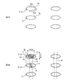
- FIG. 1A is a schematic perspective view of the laminated body 1
- FIG. 1B is a diagram showing a state in which the laminated body 1 is separated into a non-woven fabric 2 and a sheet 3.
- 2A is an enlarged view of the A region of FIG. 1B
- FIG. 2B is an enlarged view of the A region of FIG. 1B when the hot melt adhesive is applied.
- It is a partially enlarged view of the laminated body 1.
- 4A and 4B are views showing an example of the arrangement position of the hot melt adhesive 6 when joining the nonwoven fabric 2 and the sheet 3 according to the present embodiment.
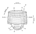
- It is a schematic perspective view of the diaper 20.
- FIG. 5 is a schematic plan view of the unfolded and stretched diaper 20 as viewed from the skin side.
- FIG. 5 is a schematic plan view of the unfolded and stretched diaper 20 as viewed from the skin side.
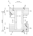
- FIG. 5 is a schematic plan view of the unfolded and stretched diaper 20 as viewed from the non-skin side.
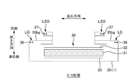
- FIG. 6 is a schematic cross-sectional view taken along the line CC in FIG.
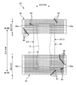
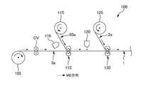
- FIG. 5 is a schematic plan view of the unfolded and stretched diaper 20 in another embodiment as viewed from the non-skin side. It is a figure explaining the structure of the manufacturing apparatus 100 which manufactures a laminated body 1.
- a laminate having a nonwoven fabric having a plurality of openings and a sheet, and an edge portion of the plurality of openings adjacent to a certain opening has at least a non-melted portion
- the nonwoven fabric and the sheet Is a laminate characterized in that it is bonded to each other by a hot melt adhesive, and the certain openings have a region overlapping with the hot melt adhesive.
- each opening is difficult to melt, and at least a part of the edge adjacent to each opening is hard. Has flexibility without.
- the shape of the pores can be maintained by arranging the hot melt adhesive so as to overlap the pores having such flexibility and joining the non-woven fabric and the sheet.
- the opening is an elliptical shape having a major axis and a minor axis, and the elliptical major axis is parallel to the fiber orientation direction of the nonwoven fabric having the opening. Is desirable.
- the pores are generated by scraping the fibers of the non-woven fabric, so that the fibers are close to the edge adjacent to the pore and the edge portion.
- the basis weight of is high.
- the edge adjacent to the opening has the elliptical major axis oriented with the non-woven fabric fibers as compared with the case where the elliptical minor axis is parallel to the fiber orientation direction of the non-woven fabric. Since it is along the fiber flow when it is parallel to the direction, it is difficult to make a height difference between the major axis direction and the minor axis direction.
- the air permeability can be maintained by ensuring the opening, and the appearance of the opening is also good.
- the opening is an elliptical shape having a major axis and a minor axis, and when the direction along the minor axis of the elliptical shape is the minor axis direction, the hot melt adhesive is said to be the same. It is desirable that a certain opening is provided so as to straddle the minor axis direction.
- the pores are generated by scraping the fibers, so that the force for the fibers to return remains, but the hot melt adhesive opens the pores.
- the fibers so as to straddle the minor axis direction, the movement of the fibers inward in the minor axis direction can be stopped and the shape of the opening can be secured.
- the density of the edge adjacent to the hole increases along the major axis direction. Therefore, by providing a hot melt adhesive so as to straddle the minor axis direction, the density increases. The high edge of the hole can be maintained without being crushed, and the shape of the hole is more secured.
- the laminated body has a longitudinal direction and a lateral direction orthogonal to each other, and both ends of the laminated body in the lateral direction include the plurality of openings, respectively, of the laminated body. It is desirable that both ends in the lateral direction are not joined by a hot melt adhesive.
- both ends where the holes are present are soft, and at both ends, the non-woven fabric and the sheet are not bonded with a hot melt adhesive, so that both ends do not become hard.
- the edges often come into direct contact with the skin, and the soft edges, which often come into direct contact with the skin, make the skin feel good and prevent the skin from being damaged.
- the region of the laminated body that overlaps with the hot melt adhesive is larger than the region that does not overlap with the hot melt adhesive in the opening.
- the region not overlapping with the hot melt adhesive in one hole having a region overlapping with the hot melt adhesive, the region not overlapping with the hot melt adhesive may be larger than the region overlapping with the hot melt adhesive.
- the region overlapping with the hot melt adhesive is larger than the region not overlapping, the shape of the pores can be more maintained.
- the appearance of the opening can be maintained.
- the region of the laminated body that overlaps with the hot melt adhesive is smaller than the region that does not overlap with the hot melt adhesive in the opening.
- the first hole is defined as the first hole. It is desirable that the region of the hole overlapping the hot melt adhesive and the region of the second hole overlapping the hot melt adhesive are different.
- the region of each of the first hole and the second hole overlapping with the hot melt adhesive is different, so that the region of each hole overlapping with the hot melt adhesive becomes non-uniform. .. Due to the non-uniformity, the cured portion of the hot melt adhesive is dispersed in each hole, so that the feel of the non-woven fabric is improved.
- the number of openings having a region overlapping with the hot melt adhesive per unit area is larger than the number of holes having only a region not overlapping with the hot melt adhesive. Is desirable.
- hot melt adhesion is performed as compared to the case where the number of openings having only the area not overlapping with the hot melt adhesive is larger than the number of openings having the area overlapping with the hot melt adhesive. Since the number of openings having a region overlapping with the agent is larger, the proportion of openings that can be maintained by the hot melt adhesive is increased. By maintaining more of the shape of the holes, the aesthetic appearance of the holes is also improved.
- the number of openings having a region overlapping with the hot melt adhesive per unit area is smaller than the number of holes having only a region not overlapping with the hot melt adhesive. Is desirable.
- the number of openings having only a region that does not overlap with the hot melt adhesive is smaller than the number of openings having an area that overlaps with the hot melt adhesive.
- the sheet is such a laminated body and does not have holes.
- the length in the longitudinal direction and the length in the lateral direction of the region where the hot melt adhesive is present so as to overlap the opening are the diameters of the circumscribed circles of the opening. It is desirable that each is longer than.
- the area where the hot melt adhesive exists is larger than the diameter of the circumscribed circle of the opening, that is, the hot melt adhesive is arranged so as to cover the entire opening. , The shape of the opening can be maintained more, and the appearance can be maintained without the opening being crushed.
- the length of the region where the hot melt adhesive exists so as to overlap the opening is shorter than the diameter of the circumscribed circle of the opening. ..
- a hole does not overlap with the hot melt adhesive because the length of the region where the hot melt adhesive is present is shorter than the diameter of the circumscribed circle of the hole.
- an absorbent article by providing a laminate having excellent touch and breathability in which the shape of the pores having flexibility is maintained, the breathability and flexibility of the waist circumference can be ensured. It is possible to provide an absorbent article in which the shape of the opening is visible.
- the absorbent article has a longitudinal direction and a left-right direction intersecting each other in a developed state, and an elastic member that expands and contracts in the left-right direction is provided between the non-woven fabric and the sheet, and the plurality of the absorbent articles.
- the opening is an elliptical shape having a major axis and a minor axis, respectively, and when the direction along the minor axis of the elliptical shape is the longitudinal direction and the direction along the major axis is the left-right direction, the elastic member And, the long axis of a certain hole among the plurality of holes is parallel to the left-right direction, and the edge portion of the said hole along the left-right direction is dense and said hot. It is desirable that the melt adhesive is provided so as to straddle the opening in the longitudinal direction.
- the shape of the opening is not easily crushed even if the elastic member contracts in the left-right direction.
- the edge portion along the left-right direction (long axis direction) of the hole becomes high density, and in this state, the hot melt adhesive straddles the hole in the longitudinal direction (minor axis direction). Therefore, the edge portion is made highly rigid, and the shape of the opening is more secured. Therefore, even if the elastic member contracts in the left-right direction, the opening is easily visible and the air permeability can be maintained.
- a method for producing a laminate which comprises joining the nonwoven fabric and the sheet to each other by applying a hot melt adhesive so as to have a region overlapping with a certain opening.
- the hot melt adhesive is arranged so as to overlap the flexible opening due to the non-melted portion of the edge adjacent to the opening, and the non-woven fabric and the sheet are joined.
- the shape of the hole can be maintained and the air permeability is improved.
- the non-woven fabric having a plurality of openings and a sheet, and the edge portion adjacent to the opening of the plurality of openings is an apparatus for producing a laminated body having at least a non-melted portion.
- FIG. 1A is a schematic perspective view of the laminated body 1
- FIG. 1B is a diagram showing a state in which the laminated body 1 is separated into a non-woven fabric 2 and a sheet 3.
- 2A is an enlarged view of the A region of FIG. 1B
- FIG. 2B is an enlarged view of the A region of FIG. 1B when the hot melt adhesive is applied.
- FIGS. 1A is a schematic perspective view of the laminated body 1
- FIG. 1B is a diagram showing a state in which the laminated body 1 is separated into a non-woven fabric 2 and a sheet 3.
- 2A is an enlarged view of the A region of FIG. 1B
- FIG. 2B is an enlarged view of the A region of FIG. 1B when the hot melt adhesive is applied.
- the laminated body 1 includes a non-woven fabric 2 which is a non-woven fabric having a plurality of holes 5 penetrating the front and back at intervals, and a liquid-impermeable and moisture-permeable sheet member. It has a two-layer structure having the sheet 3 and the non-woven fabric 2 and the sheet 3 are bonded to each other by a hot melt adhesive or the like. A specific method for joining the non-woven fabric 2 and the sheet 3 will be described later.
- the material fiber constituting the non-woven fabric 2 examples include polypropylene (PP), polyethylene (PE), polyethylene terephthalate (PET) and the like. Further, it is also possible to use not only a single fiber such as polypropylene or polyethylene but also a composite fiber (Bico) having a core-sheath structure made of polypropylene or polyethylene.
- the non-woven fabric examples include a thermal-bonded non-woven fabric, a spunbonded non-woven fabric, and a spunlaced non-woven fabric. Further, as the material constituting the sheet 3, for example, in addition to the non-woven fabric similar to the above, a resin film or the like can be mentioned, and it can also be used as a support sheet for the non-woven fabric 2.
- the nonwoven fabric 2 has a plurality of openings 5, but both the nonwoven fabric 2 and the sheet 3 have a plurality of openings 5, respectively. It may be provided.
- the formation of the pores 5 is heated, for example. It can be performed by using a pin member (not shown) or the like. At that time, the temperature of the pin member is usually set to be equal to or higher than the melting point of the fiber or film material. When the temperature of the pin member for opening the hole is equal to or higher than the melting point of each material, the edge portion adjacent to the opening is melted and solidified, and the opening is formed. However, although the shape of the hole can be maintained by the above method, the hole may become hard.
- the temperature of the pin member (not shown) at the time of forming the openings 5 is within the softening point of the fiber and below the melting point. I am trying to do it.
- the fibers of the edge portion 5a (see FIG. 2A) adjacent to the opening 5 are less likely to be melted with each other. Whether or not the fibers are melted can be confirmed by enlarging the fibers using a microscope or the like.
- the edge portion 5a of the opening 5'in FIG. 2A has an unmelted portion 5ah that is at least partially unmelted, whereby the opening 5'is flexible without becoming hard.
- the position of the non-melted portion 5ah may be different for each opening 5, and there may be an opening 5 in which all of the non-melted portions 5ah are non-melted portions 5ah.
- the temperature of the pin member is similarly kept above the softening point of the material and below the same melting point to make it difficult to melt the edge portion adjacent to the opening.
- the softening point can be measured according to JISK7196 (softening temperature test method by thermomechanical analysis of thermoplastic film and sheet).
- the melting peak temperature measured by DSC (differential scanning calorimetry) according to JISK7121 can be used as the above melting point.
- FIG. 2B shows an example of the openings 5 of the nonwoven fabric 2 after the hot melt adhesive 6 is applied.
- the opening 5' has a region 10 (a portion indicated by a diagonal line downward to the left) that overlaps with the hot melt adhesive 6.
- the edge 5a of the openings 5'(not only each opening 5) has at least a non-melted portion 5ah (FIG. 2A) as described above, whereby the opening 5'has a flexible opening.
- the holes 5 are formed, and the shape of the holes 5'can be maintained by arranging the hot melt adhesive 6 so as to overlap the holes 5'.
- the shape of the opening 5' By maintaining the shape of the opening 5', good air permeability can be ensured. Thereby, while ensuring the flexibility of the non-woven fabric 2 itself, the shape of the plurality of openings 5 having the region 10 overlapping with the hot melt adhesive 6 is maintained, and the laminate 1 having excellent touch and breathability is provided. Is possible.
- the hot melt adhesive for example, EVA type, elastomer type, olefin type, polyester / polyamide type and the like can be used.
- EVA type EVA type, elastomer type, olefin type, polyester / polyamide type and the like
- the agent include a hot melt adhesive using an olefin-based material as the base polymer.
- known coating methods such as spiral coating that can be applied in a spiral shape, omega coating that can be applied in a wavy shape, and control seam coating can be exemplified.
- the opening 5' has an elliptical shape having a minor axis 5X and a major axis 5Y, and the major axis 5Y has an opening 5'.
- the fiber orientation direction is the direction along which the fibers of the non-woven fabric 2 are aligned.
- the orientation ratio of the constituent fibers is the mechanical direction (when the non-woven fabric is manufactured). It becomes a relatively high state in the MD direction).
- the orientation direction of the fibers of the non-woven fabric 2 is aligned along the continuous direction in which the non-woven fabric 2 is continuous. Therefore, here, the machine direction in which the non-woven fabric 2 is continuously conveyed is referred to as a fiber orientation direction.
- the opening 5 When the opening 5 is formed in the non-woven fabric 2, the opening 5 is generated by scraping the fibers of the non-woven fabric 2, so that the fiber is formed in the edge portion 5a (see FIG. 2A) adjacent to the opening 5.
- the basis weight (fiber amount per unit area) of the edge portion 5a becomes higher.
- the edge portion 5a adjacent to the opening 5 has a fiber orientation of the non-woven fabric 2 in the short axis direction (X direction in FIG. 2B) along the elliptical minor axis 5X. Compared with the case of making it parallel to the direction, the case where the long axis direction (Y direction in FIG.
- each opening 5 is not stable when the nonwoven fabric 2 is pulled along the direction in which the nonwoven fabric 2 is continuous, but the height is low.
- each opening 5 is hard to be crushed and the shape is easy to be stable. As a result, since each opening 5 can be secured, the air permeability can be maintained, and each opening 5 can be visually recognized, so that it can be recognized that the air permeability is improved.
- the hot melt adhesive It is desirable that 6 is provided so as to straddle the opening 5'in the minor axis direction (X direction).
- the openings 5 are formed in the non-woven fabric 2, the openings 5 are generated by scraping the fibers, so that the force for the fibers to return remains, but the hot melt adhesive 6 is shorter than the openings 5.
- the movement of the fiber toward the inside in the minor axis direction (X direction) can be stopped, and the shape of the opening 5 can be secured.
- the edge portion 5a adjacent to the opening 5 has a high density along the major axis direction. Therefore, by providing a hot melt adhesive so as to straddle the minor axis direction, The dense edge portion 5a can be maintained without being crushed, and the shape of the opening 5 is more secured.
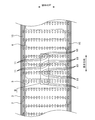
- FIG. 3 is a partially enlarged view of the laminated body 1 when the nonwoven fabric 2 and the sheet 3 are joined with a hot melt adhesive.
- the laminated body 1 has a longitudinal direction and a lateral direction orthogonal to each other, and a plurality of openings 5 are provided at both ends 15 and 15 in the lateral direction, respectively. It is desirable that the non-woven fabric 2 and the sheet 3 are not joined by the hot melt adhesive 6 at both end portions 15 and 15 provided with the plurality of openings 5. Both ends 15 and 15 having a plurality of openings 5 have flexibility, and the non-woven fabric 2 and the sheet 3 are not joined with the hot melt adhesive 6 at both ends 15 and 15, so that both ends are not joined.
- Both ends 15 and 15 are likely to come into direct contact with the skin when the laminated body 1 is used, and each end portion 15 which has many opportunities to come into direct contact with the skin has flexibility, so that the skin feels good and the skin is softened. It can be hard to hurt.
- the overlapping regions 10 are the non-overlapping regions 11 (opening of FIG. 2B). It is desirable that it is larger than the sum of the regions 11 in the hole 5'. As a result, the region 10 that overlaps with the hot melt adhesive 6 is larger than the region 11 that does not overlap with the hot melt adhesive 6 as compared with the case where the region 11 that does not overlap with the hot melt adhesive 6 is made larger than the region 10 that overlaps with the hot melt adhesive 6. It is possible to maintain the shape of the opening 5'more. By maintaining the shape of the opening 5', the aesthetic appearance of the opening 5'can be maintained.
- the region 10 that overlaps with the hot melt adhesive 6 may be smaller than the region 11 that does not overlap with the hot melt adhesive 6.
- the area where the non-overlapping region 11 overlaps with the hot melt adhesive 6 is larger than the area 10 where the hot melt adhesive 6 overlaps, as compared with the case where the non-overlapping region 11 overlaps with the hot melt adhesive 6.
- the overlap with the hot melt adhesive 6 which tends to be an obstacle can be reduced, and more air permeability can be secured.
- a hole 5' is a first hole 5'
- a hole having a region 10 overlapping the hot melt adhesive 6 which is different from the hole 5' is a second hole.
- the region 10 overlapping the hot melt adhesive 6 in the first hole 5 ′ is different from the region 10 overlapping the hot melt adhesive 6 in the second hole 5 ′′.
- each shape may be different, or the position of the overlapping region 10 in each opening may be different. Since the overlapping regions 10 of the first holes 5 ′ and the second holes 5 ′′ are different, the overlapping regions 10 of the holes 5 ′ and the hot melt adhesive 6 of the holes 5 ′′ become non-uniform.
- the holes 5'and 5' will be regular after the hot melt adhesive 6 has hardened. There is a possibility that a hard part will be formed on the surface and it will not feel good on the skin. Further, if the holes 5 other than the holes 5'and 5'are also uniform, regular hard spots may occur in the entire non-woven fabric 2, and the entire non-woven fabric may not feel good to the touch. .. However, by making the region 10 overlapping with the hot melt adhesive 6 non-uniform, the cured portion of the hot melt adhesive 6 is dispersed in each of the holes 5'5'', so that the texture of the non-woven fabric 2 is improved. To do.
- the number of openings 5 having a region 10 overlapping with the hot melt adhesive 6 per unit area is the number of holes 5 having only a region 11 not overlapping with the hot melt adhesive 6. More is desirable. As an example, looking at the B region of the non-woven fabric 2 in FIG. 3, of the 12 openings 5 in the B region, 9 are the openings 5 having the region 10 overlapping with the hot melt adhesive 6, and the hot melt There are three openings 5 having only the region 11 that does not overlap with the adhesive 6. The number of holes 5 having only the region 11 that does not overlap with the hot melt adhesive 6 is larger than the number of holes 5 having only the region 10 that overlaps with the hot melt adhesive 6.
- the proportion of the openings 5 that can maintain the shape of the openings 5 by the hot melt adhesive 6 increases. Since the shape of the opening 5 can be maintained more, the appearance of the opening 5 becomes better and the opening 5 can be more visually recognized.
- the number of openings 5 having the region 10 overlapping with the hot melt adhesive 6 existing per unit area is the number of the openings 5 having only the region 11 not overlapping with the hot melt adhesive 6. It may be less than the number.
- the number of holes 5 having only the region 11 that does not overlap with the hot melt adhesive 6 is smaller than the number of holes 5 having only the region 10 that overlaps with the hot melt adhesive 6, as compared with the case where the hot melt adhesive 6 has only the region 11. Since the number of openings 5 having only the region 11 that does not overlap with the above is larger, the air permeability can be further ensured.
- the sheet 3 has a plurality of openings 5 is also considered, but the sheet 3 does not have to have the openings 5. Since the sheet 3 does not have the holes 5, it is possible to reduce the possibility that the hot melt adhesive 6 seeps out from the holes 5 when the non-woven fabric 2 and the sheet 3 are joined.
- FIGS 4A and 4B are diagrams showing an example of the arrangement position of the hot melt adhesive 6 when joining the nonwoven fabric 2 and the sheet 3 according to the present embodiment.
- the region where the hot melt adhesive 6 is provided so as to overlap with a certain opening 5' is shown as H1 (region indicated by a dot pattern).
- the length of the existence region H1 in the longitudinal direction is H1S
- the length of the existence region H1 in the lateral direction is H1L.
- the diameter of the circumscribed circle C1 drawn so as to circumscribe with a certain opening 5' is C10.
- the length H1S in the longitudinal direction of the region H1 in which the hot melt adhesive 6 exists is preferably longer than the diameter C10 of the circumscribed circle C1.
- the length H1L of the existing region H1 in the lateral direction is preferably longer than the diameter C10 of the circumscribed circle C1.
- the region H1 in which the hot melt adhesive 6 exists is larger in both the longitudinal direction and the lateral direction than the diameter C10 of the circumscribed circle C1 of the opening 5', that is, the entire opening 5'is formed.
- the length H1S in the lateral direction of the region H1 in which the hot melt adhesive 6 exists so as to overlap with the opening 5' is the opening 5'. It may be shorter than the diameter C10 of the circumscribed circle C1 of.
- FIG. 5 is a schematic perspective view of the diaper 20.
- FIG. 6 is a schematic plan view of the unfolded and stretched diaper 20 as viewed from the skin side.
- FIG. 7 is a schematic plan view of the unfolded and stretched diaper 20 as viewed from the non-skin side.
- FIG. 8 is a schematic cross-sectional view taken along the line CC in FIG.
- the above-mentioned “deployed state” refers to both ends of the ventral waist circumference portion (ventral waist circumference portion 40 described later) and the dorsal waist circumference portion (dorsal side described later) in the width direction (left-right direction) of the diaper 1.
- the "extended state" of the diaper 20 is a state in which the entire diaper 20 (the entire product) is extended without wrinkles, specifically, each member constituting the diaper 20 (for example, the absorbent body 30 described later, and the like. It refers to a state in which the dimensions of the waist circumference 40, 50, etc.) are extended until they match or are close to the dimensions of the member alone.
- the diaper 20 has a vertical direction, a width direction, and a front-back direction that intersect each other in the pants-shaped state shown in FIG.
- the diaper 20 has an absorbent main body 30 that is applied to the crotch part of the wearer and absorbs liquid such as excrement, a ventral waist circumference 40 that covers the ventral side of the wearer, and a dorsal part of the wearer. It is a so-called three-piece type disposable diaper having a dorsal waist circumference portion 50 for covering.
- the diaper 20 has a longitudinal direction and a left-right direction that intersect each other.
- One side in the longitudinal direction in this deployed state is also referred to as “ventral” or “anterior”
- the other side in the longitudinal direction is also referred to as “dorsal” or “rear”.
- the longitudinal direction in the unfolded state is the direction along the vertical direction in the pants-shaped state.
- the thickness direction is the direction in which the materials constituting the diaper 20 are laminated.
- the side in contact with the wearer in the thickness direction is the skin side, and the opposite side is the non-skin side.
- the absorbent main body 30 is hung and fixed between the ventral waist circumference portion 40 and the dorsal waist circumference portion 50 arranged substantially in parallel.
- the absorbent body 30 is folded in half at the central portion C in the longitudinal direction thereof, and the ventral waist circumference 40 and the dorsal waist circumference 50 facing each other are mutually opposed at the lateral edge portions 40e and 50e.
- the diaper 20 is in a worn state in which the waist opening HB and the pair of leg openings HL as shown in FIG. 5 are formed.
- the absorbent main body 30 absorbs a liquid-absorbing core 31 and a liquid-permeable top sheet 32 arranged by covering the absorbent core 31 from the skin side in the thickness direction. It has a back sheet 33 arranged so as to cover the sex core 31 from the non-skin side in the thickness direction.
- An exterior sheet 35 that forms the exterior of the diaper 20 is provided on the non-skin side of the absorbent body 30.
- the laminate 1 of the present embodiment is used as the exterior sheet 35.
- the absorbent core 31 is a member formed by laminating a liquid absorbent material, and can absorb excrement such as urine.
- a liquid-absorbing fiber such as pulp fiber can be used.
- the absorbent core 11 may contain, for example, a highly absorbent polymer as the liquid absorbent granules, or may contain a liquid absorbent material other than the liquid absorbent fibers and the liquid absorbent granules. Is also good.
- the shape of the absorbent core 31 is not limited to the shape of an hourglass in a plan view as shown in FIG. 6, and may be, for example, a substantially rectangular shape in a plan view. Further, the absorbent core 31 may have a liquid-permeable core wrap sheet (not shown).
- the top sheet 32 is, for example, a flat-sized liquid-permeable non-woven fabric larger than the absorbent core 31.
- the back sheet 33 is a sheet-like member that covers the absorbent core 31 from the non-skin side, and is a flat-sized sheet larger than the absorbent core 31.
- An example of the back sheet 33 is a liquid-impermeable leak-proof sheet such as polyethylene or polypropylene.
- the laminate 1 of the present embodiment as the exterior sheet 35 is provided so that the non-woven fabric 2 side, which is a perforated non-woven fabric, is the most non-skin side surface of the diaper 20.
- the horizontal dimension of the exterior sheet 35 (1) is sufficiently larger than that of the back sheet 33, that is, the exterior sheet 35 (1) is a back sheet. It protrudes greatly from both sides in the left-right direction of 33 to the outside in the left-right direction. Then, the so-called three-dimensional gather LSG and the leg circumference gather LG are formed by the exterior sheet 35 (1).
- the three-dimensional gather LSG is a leak-proof wall portion provided upright at each end of the top sheet 32 in the left-right direction, while the leg gather LG is formed in the openings HL and HL around each leg of the diaper 20. It is a stretchable part around the leg. Then, the protruding portion of the exterior sheet 35 (1) described above is folded back toward the center in the left-right direction with both ends of the absorbent body 30 in the left-right direction as folded positions, and is folded along the longitudinal direction in the vicinity of the folded-back position. An elastic member 36 around the leg, such as a rubber thread, is fixed in a state of being extended in the longitudinal direction, whereby the above-mentioned gather around the leg LG is formed.
- the portion 35 bg (FIG. 8) folded back to the center side in the left-right direction further extends to the center side in the left-right direction and is joined to the same end portion at a position covering the end portion in the left-right direction of the top sheet 32. Then, a portion on the tip end side in the left-right direction can stand up from the top sheet 32 as a free end portion than the portion joined to the end portion.
- An elastic member 37 such as a rubber thread is fixed to each free end portion in a state of being extended in the longitudinal direction, and contracts in the longitudinal direction by a contraction force applied from the elastic member 37 to stand up. As a result, it functions as a three-dimensional gather LSG.
- the laminated body 1 used as the exterior sheet 35 has holes 5 on both end sides in the left-right direction of the exterior sheet 35 (1), that is, in the lateral direction of the laminated body 1. (The area where the dotted line portion of the exterior sheet 35 (1) in FIG. 8 has an opening 5) is not provided.
- the air permeability can be improved by providing a plurality of openings 5, but the outer side in the left-right direction of the absorbent main body 30.
- the absence of the plurality of openings 5 makes it possible to avoid giving the impression that leakage occurs from the openings 5.
- the position where the opening 5 of the laminated body 1 as the exterior sheet 35 is provided is not limited to the above, and may be the entire exterior sheet 35 or a smaller area.
- the non-absorbent main body 30 that absorbs the liquid is provided with the laminated body 1 having excellent touch and breathability while maintaining the shape of the open holes 5 having flexibility. Breathability and flexibility on the sides of the skin can be ensured. Further, since the shapes of the plurality of openings 5 can be visually recognized, it is possible to provide a visual effect of showing good breathability to the wearer.
- FIG. 9 is a schematic plan view of the unfolded and stretched diaper 20 as viewed from the non-skin side in another embodiment in which the laminated body 1 is used for the diaper 20.
- the laminated body 1 is used as the ventral waist circumference portion 40 and the dorsal waist circumference portion 50 of the diaper 20, and the non-woven fabric 2 of the laminated body 1 is arranged so as to be on the non-skin side most.
- a plurality of elastic members 60 that expand and contract in the left-right direction are provided between the non-woven fabric 2 and the sheet 3 of the laminate 1 used in the diaper 20 of FIG. 9 in a state of being extended in the left-right direction. .. Further, the plurality of openings 5 of the ventral waist circumference portion 40 (1) and the dorsal waist circumference portion 50 (1) have an elliptical shape having a major axis and a minor axis, respectively (similar to each opening 5 in FIG. 2B). .. Further, when the direction along the elliptical short axis (5X in FIG. 2B) is the longitudinal direction of the diaper 20 and the direction along the long axis (5Y in FIG.
- FIG. 2B is the left-right direction of the diaper 20, the ventral waist circumference 40 (5X in FIG. 2B)
- Each elastic member 60 provided on 1) and the dorsal waist circumference 50 (1) and the long axis 5Y of the opening 5'among the plurality of openings are parallel to the left-right direction of the diaper 20. It is desirable to be.
- the hot melt adhesive 6 straddles at least a part of the openings 5 in the longitudinal direction of the diaper 20. (That is, so as to straddle the elliptical short axis direction).
- the shape of the opening 5 is less likely to be crushed. Further, when the opening 5 is formed, the portion of the edge portion 5a of the opening 5 along the left-right direction (major axis direction) has a high density due to the fibers being gathered together, and hot-melt adhesion is performed in this state. Since the agent 6 is provided so as to straddle the opening 5 in the longitudinal direction (minor axis direction), the edge portion 5a is made highly rigid by holding such a high-density region, and the shape of the opening 5 is formed. Is more secured. Therefore, even if the elastic member 60 contracts in the left-right direction, the opening 5 is easily visible and the air permeability can be maintained.
- FIG. 10 is a diagram illustrating a configuration of a manufacturing apparatus 100 for manufacturing the laminated body 1.
- the manufacturing apparatus 100 includes a step of joining the elastic members on the assumption that an elastic member is arranged between the nonwoven fabric 2 and the sheet 3 of the laminated body 1, but the manufacturing apparatus 100 includes a step of joining the elastic members between the nonwoven fabric 2 and the sheet 3. If the elastic member is not arranged, this step can be omitted.
- the manufacturing apparatus 100 of the present embodiment includes a transport mechanism CV, a coating device 116 for applying a hot melt adhesive, an elastic member joining portion 110, a coating device 120 for applying the hot melt adhesive 6, and a joining device 130. Has.
- the transport mechanism CV is a transport unit that continuously transports the sheet 3 along a predetermined transport path.
- a transport roller for example, a transport roller, a suction belt conveyor having a suction holding function on the belt surface serving as a mounting surface, or the like is used.
- the continuous sheet of the sheet 3 to be conveyed is referred to as a continuous sheet 3a.
- the transport direction of each member set on the manufacturing apparatus 100 is also referred to as "MD direction".
- the continuous sheet 3a is unwound from the sheet roll 105 in which the continuous sheet 3a is wound in a roll shape.
- the fed continuous sheet 3a is conveyed from the upstream side to the downstream side in the MD direction at a predetermined transfer speed by the transfer mechanism CV, and reaches the position where the elastic member joint 110 is arranged.
- a continuous elastic member 60a in a state where a plurality of elastic members 60 such as rubber threads are connected is conveyed from the elastic member roll 115 in a state of being extended in the conveying direction, and before reaching the elastic member joint 110, the coating device 116 However, an adhesive such as a hot melt adhesive is applied to the elastic member 60a to be conveyed.
- the elastic member joint 110 is driven and rotated at a predetermined peripheral speed value to convey the continuous sheet 3a to the downstream side in the MD direction, while the separately supplied elastic member 60a is provided with an adhesive-coated surface. They are arranged so as to be bonded to the continuous sheet 3a and joined.
- the continuous sheet 3a to which the elastic member 60a is bonded is conveyed further downstream in the MD direction, and the coating device 120 applies the hot melt adhesive 6 to the surface of the conveyed continuous sheet 3a. After that, the continuous sheet 3a coated with the hot melt adhesive 6 reaches the position where the joining device 130 is arranged.
- the non-woven fabric continuous sheet 2a which is a continuous sheet of the non-woven fabric 2
- the non-woven fabric roll 125 around which the non-woven fabric 2 which is the perforated non-woven fabric is wound in a roll shape.
- the surface of the continuous sheet 3a on which the hot melt adhesive 6 is applied is bonded and joined.
- the laminated body 1 is manufactured by sequentially executing each of the above steps using the manufacturing apparatus 100.
- an elliptical shape is given as an example of the shape of each opening 5, but the shape can be any shape such as a perfect circle, a rectangle, a polygon such as a rhombus, or a star shape.
- the absorbent main body 30 of the diaper 20 has the back sheet 33, but the sheet 3 of the laminated body 1 is made to function as the back sheet without providing the back sheet 33, and further, the non-woven fabric is not provided.
- the laminated body 1 may be configured so that the non-woven fabric 2 which is a perforated non-woven fabric is arranged on the side as an exterior body.
- the laminated body 1 is used as the exterior sheet 35 of the diaper 20, and the three-dimensional gather LSG and the leg circumference gather LG are formed by the laminated body 1, but the three-dimensional gather LSG and the leg circumference gather LG are used.
- the laminated body 1 may be arranged on the most non-skin side surface of the diaper 20. Thereby, the flexibility and good air permeability of the laminated body 1 can be provided only in a desired portion.
Landscapes
- Health & Medical Sciences (AREA)
- Engineering & Computer Science (AREA)
- General Health & Medical Sciences (AREA)
- Biomedical Technology (AREA)
- Heart & Thoracic Surgery (AREA)
- Vascular Medicine (AREA)
- Life Sciences & Earth Sciences (AREA)
- Animal Behavior & Ethology (AREA)
- Epidemiology (AREA)
- Public Health (AREA)
- Veterinary Medicine (AREA)
- Manufacturing & Machinery (AREA)
- Dermatology (AREA)
- Textile Engineering (AREA)
- Absorbent Articles And Supports Therefor (AREA)
- Laminated Bodies (AREA)
- Nonwoven Fabrics (AREA)
- Fixed Capacitors And Capacitor Manufacturing Machines (AREA)
- Ceramic Capacitors (AREA)
Abstract
複数の開孔(5)を有する不織布(2)と、シート(3)とを有する積層体(1)であって、複数の開孔(5)のうちのある開孔(5')に隣接する縁部(5a)は、少なくとも非溶融部を有し、不織布(2)とシート(3)とは、ホットメルト接着剤(6)により互いに接合されており、ある開孔(5')は、ホットメルト接着剤(6)と重なる領域(10)を有する。
Description
本発明は、積層体及び積層体の製造方法、並びに積層体の製造装置に関する。
使い捨ておむつや生理用ナプキン等の吸収性物品の多くは、吸収した液体の透過を防止しつつ通気性を確保するために、吸収体の裏側を覆う液不透過性シートと、当該液不透過性シートの裏側を覆うカバー不織布等を備えている。特許文献1には、有孔不織布であるカバー不織布と、支持シートである液不透過性シートとを貼り合わせ、支持シートと孔とが重なる部位にホットメルト接着剤が存在しない部分を有する使い捨て着用物品を開示している。
特許文献1の使い捨て着用物品に用いられる支持シートとカバー不織布(有孔不織布)とを貼り合わせた部材(所謂、積層体)では、有孔不織布の各孔の縁部は、繊維密度がその周囲の部分と比べて同程度又は高く、また、繊維同士が融着していることが望ましいが、各孔の縁部の繊維同士が溶融して固化することで、孔の形状は保持できるものの、その部分が硬くなってしまう虞があった。
本発明は、上記のような従来の問題に鑑みてなされたものであって、その目的は、開孔を有する不織布の各開孔部分の柔軟性を確保し、別のシートと接合させた後でも開孔の形状を保持できる積層体を提供することにある。
上記目的を達成するための主たる発明は、複数の開孔を有する不織布と、シートとを有する積層体であって、前記複数の開孔のうちのある開孔に隣接する縁部は、少なくとも非溶融部を有し、前記不織布と前記シートとは、ホットメルト接着剤により互いに接合されており、前記ある開孔は、前記ホットメルト接着剤と重なる領域を有する
ことを特徴とする積層体である。
本発明の他の特徴については、本明細書及び添付図面の記載により明らかにする。
ことを特徴とする積層体である。
本発明の他の特徴については、本明細書及び添付図面の記載により明らかにする。
本発明によれば、開孔を有する不織布の各開孔部分の柔軟性を確保し、別のシートと接合させた後でも開孔の形状を保持できる積層体を提供できる。
本明細書及び添付図面の記載により、少なくとも以下の事項が明らかとなる。
複数の開孔を有する不織布と、シートとを有する積層体であって、前記複数の開孔のうちのある開孔に隣接する縁部は、少なくとも非溶融部を有し、前記不織布と前記シートとは、ホットメルト接着剤により互いに接合されており、前記ある開孔は、前記ホットメルト接着剤と重なる領域を有することを特徴とする積層体である。
複数の開孔を有する不織布と、シートとを有する積層体であって、前記複数の開孔のうちのある開孔に隣接する縁部は、少なくとも非溶融部を有し、前記不織布と前記シートとは、ホットメルト接着剤により互いに接合されており、前記ある開孔は、前記ホットメルト接着剤と重なる領域を有することを特徴とする積層体である。
このような積層体によれば、複数の開孔は、融点以下で孔が形成されているため、各開孔が溶融されにくく、各開孔に隣接する縁部の少なくとも一部は、硬くならずに柔軟性を有している。そのような柔軟性を有した開孔と重なるようにホットメルト接着剤が配されて不織布とシートとが接合されることにより、開孔の形状を維持することができる。柔軟性を確保し、複数の開孔の形状を保持できることで、肌触りと通気性に優れた積層体を提供できる。
かかる積層体であって、前記ある開孔は、長軸及び短軸を有する楕円形状であり、前記楕円形状の前記長軸は、前記ある開孔を有する前記不織布の繊維配向方向と平行であることが望ましい。
このような積層体によれば、開孔を不織布に形成する場合、開孔は不織布の繊維を掻き分けるようにして生成される為、開孔に隣接する縁部には繊維が寄り、縁部の目付は高くなる。開孔が楕円形状である場合の開孔に隣接する縁部は、楕円形状の短軸を不織布の繊維配向方向と平行とする場合と比較して、楕円形状の長軸を不織布の繊維の配向方向と平行にした方が、繊維の流れに沿っているため、長軸方向と短軸方向との目付の高低差が出来にくい。目付の高低差が大きいと、不織布を引っ張った状態にした際に開孔の形状が安定しないが、高低差が小さいと、開孔は潰れにくく、形状が安定しやすい。結果として、開孔を確保できることで通気性を保持でき、開孔の見た目も良好となる。
かかる積層体であって、前記ある開孔は、長軸及び短軸を有する楕円形状であり、前記楕円形状の前記短軸に沿う方向を短軸方向とすると、前記ホットメルト接着剤は、前記ある開孔を前記短軸方向に跨ぐように設けられていることが望ましい。
このような積層体によれば、開孔を不織布に形成する場合、開孔は繊維を掻き分けるようにして生成される為、繊維が戻ろうとする力が残るが、ホットメルト接着剤が開孔に対して短軸方向に跨ぐように設けられることで、短軸方向の内側に向かう繊維の動きを止め、開孔の形状を確保できる。また、繊維を掻き分けて開孔した際に、開孔に隣接する縁部は長軸方向に沿って密度が高くなるため、短軸方向に跨ぐようにホットメルト接着剤を設けることで、該密度の高い縁部を潰さずに維持でき、開孔の形状はより確保される。
かかる積層体であって、前記積層体は、互いに直交する長手方向と短手方向を有し、前記積層体の短手方向の両端部は、それぞれ前記複数の開孔を含み、前記積層体の前記短手方向の前記両端部は、ホットメルト接着剤によって接合されていないことが望ましい。
このような積層体によれば、開孔が存在する両端部は柔らかく、その両端部においては、不織布とシートとをホットメルト接着剤で接合しないことで、両端部が固くならない。端部は直接肌に当たることが多く、肌に直接当たる機会の多い端部が柔らかいことで、肌当たりがよく、肌を傷つけ難くすることができる。
かかる積層体であって、前記ある開孔においては、前記ホットメルト接着剤と重なる領域は、前記ホットメルト接着剤と重ならない領域よりも大きいことが望ましい。
このような積層体によれば、ホットメルト接着剤と重なる領域を有する1つのある開孔においては、ホットメルト接着剤と重なる領域よりもホットメルト接着剤と重ならない領域の方を大きくする場合と比較して、ホットメルト接着剤と重なる領域が、重ならない領域よりも大きい方が、開孔の形状をより維持することができる。開孔の形状が維持されることで、開孔の美観を保つことができる。
かかる積層体であって、前記ある開孔においては、前記ホットメルト接着剤と重なる領域は、前記ホットメルト接着剤と重ならない領域よりも小さいことが望ましい。
このような積層体によれば、ホットメルト接着剤と重なる領域よりも重ならない領域の方を小さくする場合と比較して、ホットメルト接着剤と重なる領域よりも重ならない領域を大きくする方が、通気の妨げとなり易いホットメルト接着剤との重なりを低減でき、通気性をより多く確保できる。
かかる積層体であって、前記ある開孔を第1の孔、前記ある開孔とは別の、前記ホットメルト接着剤と重なる領域を有する孔を第2の孔としたとき、前記第1の孔の前記ホットメルト接着剤と重なる領域と、前記第2の孔の前記ホットメルト接着剤と重なる領域とは異なっていることが望ましい。
このような積層体によれば、第1の孔と第2の孔ぞれぞれのホットメルト接着剤と重なる領域が異なることで、各孔のホットメルト接着剤と重なる領域は不均一になる。不均一になることで、各孔において、ホットメルト接着剤が硬化した部分が分散されるので、不織布の肌触りが向上する。
かかる積層体であって、単位面積当たりに存在する、前記ホットメルト接着剤と重なる領域を有する開孔の数は、前記ホットメルト接着剤と重ならない領域のみを有する開孔の数よりも多いことが望ましい。
このような積層体によれば、ホットメルト接着剤と重ならない領域のみを有する開孔の数がホットメルト接着剤と重なる領域を有する開孔の数よりも多い場合と比較して、ホットメルト接着剤と重なる領域を有する開孔の数の方が多いことで、ホットメルト接着剤によって開孔形状を維持できる開孔の割合が多くなる。開孔の形状をより多く維持できることによって、開孔の美観も良好となる。
かかる積層体であって、単位面積当たりに存在する、前記ホットメルト接着剤と重なる領域を有する開孔の数は、前記ホットメルト接着剤と重ならない領域のみを有する開孔の数よりも少ないことが望ましい。
このような積層体によれば、前記ホットメルト接着剤と重ならない領域のみを有する開孔の数がホットメルト接着剤と重なる領域を有する開孔の数よりも少ない場合と比べて、前記ホットメルト接着剤と重ならない領域のみを有する開孔の数の方が多いことで、通気性をより確保できる。
かかる積層体であって、前記シートは、開孔を有していないことが望ましい。
このような積層体によれば、シートには開孔が存在しないことで、不織布とシートとを接合するときに、ホットメルト接着剤が開孔から染み出る可能性を低減できる。
かかる積層体であって、前記ある開孔と重なるように設けられた前記ホットメルト接着剤の存在領域の長手方向の長さ及び短手方向の長さは、前記ある開孔の外接円の直径よりもそれぞれ長いことが望ましい。
このような積層体によれば、開孔の外接円の直径よりもホットメルト接着剤の存在領域方が大きいことで、すなわち、開孔全体を覆うようにホットメルト接着剤が配されることで、開孔の形状をより維持することができ、開孔が潰されることなく、美観が保てる。
かかる積層体であって、前記ある開孔と重なるように設けられた前記ホットメルト接着剤の存在領域の短手方向の長さは、前記ある開孔の外接円の直径よりも短いことが望ましい。
このような積層体によれば、ホットメルト接着剤の存在領域の短手方向の長さがある開孔の外接円の直径よりも短いことで、ある開孔は、ホットメルト接着剤と重ならない領域を有することになり、重ならない領域を確保することで、通気性をより維持することができる。
液体を吸収する吸収性本体と、積層体とを備えることを特徴とする吸収性物品である。
このような吸収性物品によれば、柔軟性を有した開孔の形状が維持された、肌触りと通気性に優れた積層体を備えることにより、胴回り部の通気性と柔軟性を確保でき、開孔の形状が視認できる吸収性物品を提供することができる。
かかる吸収性物品であって、展開状態において互いに交差する長手方向と左右方向とを有し、前記不織布と前記シートとの間には、前記左右方向に伸縮する弾性部材が設けられ、前記複数の開孔は、それぞれ、長軸及び短軸を有する楕円形状であり、前記楕円形状の前記短軸に沿う方向を前記長手方向、前記長軸に沿う方向を前記左右方向とするとき、前記弾性部材と、前記複数の開孔のうちのある開孔の前記長軸とは、前記左右方向に平行であり、前記ある開孔の前記左右方向に沿った縁部は、高密度であり、前記ホットメルト接着剤は、前記ある開孔を前記長手方向に跨ぐように設けられていることが望ましい。
このような吸収性物品によれば、開孔の長軸は吸収性物品の左右方向に沿っているため、弾性部材が左右方向に収縮しても、開孔の形状は潰れにくい。また、開孔を形成した際に、開孔の左右方向(長軸方向)に沿った縁部は高密度となり、かかる状態でホットメルト接着剤が開孔を長手方向(短軸方向)に跨ぐように設けられるので、該縁部は高剛性化されて、開孔の形状はより確保される。よって、弾性部材が左右方向に収縮しても、開孔は視認され易く、通気性も保持できる。
複数の開孔を有する不織布と、シートとを有し、前記複数の開孔のうちのある開孔に隣接する縁部は、少なくとも非溶融部を有する積層体を製造する方法であって、前記ある開孔と重なる領域を有するようにホットメルト接着剤を塗布することによって、前記不織布と前記シートとを互いに接合することを有することを特徴とする積層体の製造方法である。
このような製造方法によれば、開孔に隣接する縁部の非溶融部により柔軟性を有した開孔と重なるようにホットメルト接着剤を配し、且つ、不織布とシートが接合されることにより、開孔の形状を維持することができ、通気性が向上する。これにより、柔軟性にすぐれ、開孔の形状の美観も保ちつつ通気性を確保する積層体を提供できる。
複数の開孔を有する不織布と、シートとを有し、前記複数の開孔のうちのある開孔に隣接する縁部は、少なくとも非溶融部を有する積層体を製造する装置であって、前記ある開孔と重なる領域を有するようにホットメルト接着剤を塗布する塗布装置と、前記ホットメルト接着剤により、前記不織布と前記シートとを互いに接合する接合装置とを有することを特徴とする積層体の製造装置である。
このような製造装置によれば、前述した製造方法の場合と同様の作用効果を奏することができる。
===実施形態===
<積層体1の基本構成>
はじめに、本実施形態に係る積層体1の基本的構成について説明する。図1Aは、積層体1の概略斜視図であり、図1Bは、積層体1を不織布2とシート3とに分離した状態を示す図である。図2Aは、図1BのA領域の拡大図であり、図2Bは、ホットメルト接着剤を塗布したときの、図1BのA領域の拡大図である。図1A及び図1Bに示すように、積層体1は、表裏に貫通する開孔5が間隔を空けて複数設けられた開孔不織布である不織布2と、液不透過性かつ透湿性のシート部材であるシート3とを有する2層構造であり、不織布2とシート3とは、ホットメルト接着剤等により互いに接合される。不織布2とシート3とを接合する具体的な方法については、後述する。
不織布2を構成する素材繊維としては、例えば、ポリプロピレン(PP)、ポリエチレン(PE)、ポリエチレンテレフタレート(PET)等が挙げられる。また、ポリプロピレンやポリエチレンなどの単独繊維だけでなく、ポリプロピレンやポリエチレンからなる芯鞘構造の複合繊維(Bico)などを使用することも可能である。不織布の態様としては、サーマルボンド不織布、スパンボンド不織布、スパンレース不織布等が挙げられる。また、シート3を構成する素材としては、例えば、上述と同様の不織布の他に、樹脂フィルム等が挙げられ、不織布2に対する支持シートとしても使用できる。
また、本実施形態では、積層体1の不織布2及びシート3のうち、不織布2が複数の開孔5を有しているが、不織布2及びシート3の双方において、それぞれ複数の開孔5が設けられていてもよい。
尚、不織布2及びシート3が上述したポリプロピレン、ポリエチレン等の熱可塑性樹脂繊維によって構成される場合や、シート3が熱可塑性フィルム等によって構成される場合、開孔5の形成は、例えば、加熱されたピン部材(不図示)等を使用して行うことが可能である。その際、通常、ピン部材の温度が繊維やフィルム素材の融点以上に設定されることが多い。開孔を行うピン部材の温度が各素材の融点以上であることによって、開孔に隣接する縁部が溶融及び固化され、開孔が形成される。しかしながら、上述の方法により開孔の形状は保持できるものの、開孔部分が硬くなってしまう虞がある。
この点、本実施形態の不織布2に形成されている複数の開孔5については、開孔5を形成する際のピン部材(不図示)の温度が繊維の軟化点以上且つ同融点未満に収まるようにしている。それによって、開孔5に隣接する縁部5a(図2A参照)は、繊維同士が溶融されにくい。繊維同士が溶融されているか否かは、顕微鏡等を使用して繊維同士を拡大することによって確認することができる。本実施形態では、例えば、図2Aの開孔5’の縁部5aは、少なくとも一部が溶融されていない非溶融部5ahを有し、それにより、開孔5’は、硬くならずに柔軟性を有することができる。非溶融部5ahの位置は、各開孔5によって異なっていてもよく、また、全てが非溶融部5ahである開孔5が存在してもよい。尚、シート3に開孔を形成する場合も、同様にピン部材の温度が素材の軟化点以上且つ同融点未満に収まるようにすることで、開孔に隣接する縁部を溶融させにくくし、該縁部が少なくとも非溶融部5ahを有することで、柔軟性を保持することができる。
ちなみに、軟化点については、JISK7196(熱可塑性プラスチックフィルム、及び、シートの熱機械分析による軟化温度試験方法)に準じて測定できる。また、融点については、JISK7121(プラスチックの転移温度測定方法)に準じて、DSC(示差走査熱量測定)を用いて測定される融解ピーク温度を、上記の融点とすることができる。
そして、本実施形態に係る不織布2とシート3とは、ホットメルト接着剤6によって接合されるが、ホットメルト接着剤6が塗布された後の不織布2の開孔5の一例を図2Bに示している。各開孔5のうち、ある開孔5’を例にみると、開孔5’は、ホットメルト接着剤6と重なる領域10(左下がりの斜線で示した部分)を有している。開孔5’(のみならず各開孔5)の縁部5aは、上述のように少なくとも非溶融部5ah(図2A)を有し、それにより、開孔5’は柔軟性を備えた開孔5であり、そのような開孔5’と重なるようにホットメルト接着剤6が配されることで、開孔5’の形状を維持できる。開孔5’の形状を保つことによって、良好な通気性を確保することができる。それにより、不織布2自体の柔軟性を確保しつつ、ホットメルト接着剤6と重なる領域10を有する複数の開孔5の形状を保持し、肌触りと通気性に優れた積層体1を提供することが可能となる。
ホットメルト接着剤としては、例えば、EVA系、エラストマー系、オレフィン系、ポリエステル・ポリアミド系などを使用できる。なお、接合後の積層体1においては、塗布された上記ホットメルト接着剤6が不織布2の開孔5から露出しているため、不織布2の表面を触れた際にべたついてしまう虞がある。よって、これを防ぐべく、望ましくは、タック力の小さい(すなわち、接着性が低い)低タックタイプ又はノンタックタイプのホットメルト系接着剤を用いると良く、この低タックタイプ又はノンタックタイプのホットメルト接着剤としては、ベースポリマーとしてオレフィン系の材料を用いたホットメルト接着剤を例示できる。また、ホットメルト接着剤の塗布方法としては、螺旋状に塗布できるスパイラル塗工、波状に塗布できるオメガ塗工やコントロールシーム塗工等の公知の塗布方法を例示できる。
また、図2Bに示すように、開孔5’を例にみると、開孔5’は、短軸5X及び長軸5Yを有する楕円形状であり、長軸5Yは、開孔5’を有する不織布2の繊維配向方向と平行になっていることが望ましい。ここで、繊維配向方向とは、不織布2の繊維が沿う方向であり、例えば、不織布2がスパンボンド法によって形成される不織布だった場合、不織布製造時に、その構成繊維の配向割合が機械方向(MD方向)に比較的高い状態となる。この場合、不織布2の繊維の配向方向は、不織布2が連続する連続方向に沿って揃っていることとなる。よって、ここでは、不織布2が連続して搬送される機械方向を繊維配向方向という。
そして、開孔5を不織布2に形成する場合、開孔5は不織布2の繊維を掻き分けるようにして生成される為、開孔5に隣接する縁部5a(図2A参照)には繊維が寄り、縁部5aの目付(単位面積当たりの繊維量)は高くなる。開孔5が上述のように楕円形状である場合の開孔5に隣接する縁部5aは、楕円形状の短軸5Xに沿った短軸方向(図2BのX方向)を不織布2の繊維配向方向と平行にさせる場合と比較して、長軸5Yに沿った長軸方向(図2BのY方向)を不織布2の繊維配向方向と平行にした方が、繊維の流れに沿っているため、長軸方向と短軸方向との目付の高低差が出来にくい。仮に、長軸方向と短軸方向との目付の高低差が大きいと、不織布2を不織布2が連続する方向に沿って引っ張った状態にした際に各開孔5の形状が安定しないが、高低差が小さいと、各開孔5は潰れにくく、形状が安定しやすい。結果として、各開孔5を確保できることで通気性を保持でき、各開孔5を視認できるため、通気性向上の機能を有することを認識できる。
また、図2Bに示すように、開孔5’が、短軸5X及び長軸5Yを有する楕円形状であり、短軸5Xに沿う方向を短軸方向(X方向)とすると、ホットメルト接着剤6は、開孔5’を短軸方向(X方向)に跨ぐように設けられていることが望ましい。開孔5を不織布2に形成する場合、開孔5は繊維を掻き分けるようにして生成される為、繊維が戻ろうとする力が残るが、ホットメルト接着剤6が開孔5に対して短軸方向に跨ぐように設けられることで、短軸方向(X方向)の内側に向かう繊維の動きを止め、開孔5の形状を確保できる。また、繊維を掻き分けて開孔した際に、開孔5に隣接する縁部5aは長軸方向に沿って密度が高くなるため、短軸方向に跨ぐようにホットメルト接着剤を設けることで、該密度の高い縁部5aを潰さずに維持でき、開孔5の形状はより確保される。
図3は、不織布2とシート3とをホットメルト接着剤で接合した際の積層体1の部分拡大図である。図3に示すように、積層体1は、互いに直交する長手方向と短手方向を有し、短手方向の両端部15、15には、それぞれ複数の開孔5が設けられている。そして、複数の開孔5が設けられている両端部15、15は、ホットメルト接着剤6によって、不織布2とシート3とが接合されていないことが望ましい。複数の開孔5が存在する両端部15、15は柔軟性を有しており、当該両端部15,15において、不織布2とシート3とをホットメルト接着剤6で接合しないことで、両端部15,15を硬くなりにくくすることができる。両端部15,15は、積層体1を使用する場合に直接肌と当たる可能性が高く、肌に直接当たる機会の多い各端部15が柔軟性を有することで、肌当たりが良く、肌を傷つけ難くすることができる。
また、図2Bの開孔5’においては、ホットメルト接着剤6と重なる領域を領域10とし、重ならない領域をそれぞれ領域11とした場合、重なる領域10は、重ならない領域11(図2Bの開孔5’における領域11の合計)よりも大きいことが望ましい。これにより、ホットメルト接着剤6と重なる領域10よりもホットメルト接着剤6と重ならない領域11を大きくした場合と比較して、ホットメルト接着剤6と重なる領域10が重ならない領域11よりも大きい方が、開孔5’の形状をより維持することができる。開孔5’の形状が維持されることで、開孔5’の美観を保つことができる。
また、開孔5’においては、上述とは逆に、ホットメルト接着剤6と重なる領域10は、ホットメルト接着剤6と重ならない領域11よりも小さくても良い。こうすることで、重ならない領域11がホットメルト接着剤6と重なる領域10よりも小さい場合と比較して、ホットメルト接着剤6と重ならない領域11が重なる領域10よりも大きい方が、通気の妨げとなり易いホットメルト接着剤6との重なりを低減でき、通気性をより多く確保できることになる。
さらに、図2Bに示すように、ある開孔5’を第1の孔5’、ある開孔5’とは別の、ホットメルト接着剤6と重なる領域10を有する開孔を第2の孔5’’としたとき、第1の孔5’のホットメルト接着剤6と重なる領域10は、第2の孔5’’のホットメルト接着剤6と重なる領域10と異なっている。例えば、それぞれの形状が異なっていてもよいし、それぞれの開孔における重なる領域10の位置が異なっていてもよい。第1の孔5’と第2の孔5’’のそれぞれの重なる領域10が異なることで、各孔5’及び孔5’’のホットメルト接着剤6と重なる領域10は不均一になる。仮に、孔5’及び孔5’’のホットメルト接着剤6と重なる領域10が均一であった場合、各孔5’、孔5’’は、ホットメルト接着剤6が硬化した後に、規則的に硬い箇所が生じてしまい肌触りがよくない可能性がある。更に、各孔5’、孔5’’以外の孔5も同様に均一となった場合は、不織布2全体において規則的に硬い箇所が生じてしまい、不織布全体について肌触りがよくない可能性がある。しかし、ホットメルト接着剤6と重なる領域10を不均一にすることで、各孔5’、5’’において、ホットメルト接着剤6が硬化した部分が分散されるので、不織布2の肌触りが向上する。
また、本実施形態において、単位面積当たりに存在する、ホットメルト接着剤6と重なる領域10を有する開孔5の数は、ホットメルト接着剤6と重ならない領域11のみを有する開孔5の数よりも多いことが望ましい。例として、図3の不織布2のB領域についてみると、B領域内の12個の開孔5のうち、ホットメルト接着剤6と重なる領域10を有する開孔5は9個であり、ホットメルト接着剤6と重ならない領域11のみを有する開孔5は3個である。ホットメルト接着剤6と重ならない領域11のみを有する開孔5の数が、ホットメルト接着剤6と重なる領域10を有する開孔5の数よりも多い場合と比較して、ホットメルト接着剤6と重なる領域10を有する開孔5の数の方が多いことで、ホットメルト接着剤6によって開孔5の形状を維持できる開孔5の割合が多くなる。開孔5の形状をより多く維持できることによって、開孔5の美観もより良好となり、開孔5をより視認できる。
また、上述とは逆に、単位面積当たりに存在する、ホットメルト接着剤6と重なる領域10を有する開孔5の数は、ホットメルト接着剤6と重ならない領域11のみを有する開孔5の数よりも少なくても良い。ホットメルト接着剤6と重ならない領域11のみを有する開孔5の数が、ホットメルト接着剤6と重なる領域10を有する開孔5の数よりも少ない場合と比べて、前記ホットメルト接着剤6と重ならない領域11のみを有する開孔5の数の方が多いことで、通気性をより確保できる。
尚、上記では、シート3が複数の開孔5を有している場合も考慮したが、シート3は、開孔5を有していなくても良い。シート3に開孔5が存在しないことで、不織布2とシート3とを接合するときに、ホットメルト接着剤6が各開孔5から染み出る可能性を低減することができる。
図4A及び図4Bは、本実施形態に係る不織布2及びシート3を接合する際の、ホットメルト接着剤6の配置位置の例を示す図である。ここでは、ある開孔5’と重なるように設けられたホットメルト接着剤6の存在領域をH1(ドット模様で示した領域)として示している。存在領域H1の長手方向の長さはH1Sであり、存在領域H1の短手方向の長さはH1Lである。また、ある開孔5’と外接するように描いた外接円C1の直径をC10としている。ホットメルト接着剤6の存在領域H1の長手方向の長さH1Sは、外接円C1の直径C10よりも長いことが好ましい。また、存在領域H1の短手方向の長さH1Lは、外接円C1の直径C10よりも長いことが好ましい。このように、開孔5’の外接円C1の直径C10よりもホットメルト接着剤6の存在領域H1の方が長手方向においても短手方向においても大きいことで、すなわち、開孔5’全体を覆うようにホットメルト接着剤6が配されることで、開孔5’の形状をより維持することができ、開孔5’が潰されることなく、美観を保つことができる。
また、上述とは異なり、図4Bに示すように、ある開孔5’と重なるように設けられたホットメルト接着剤6の存在領域H1の短手方向の長さH1Sは、ある開孔5’の外接円C1の直径C10よりも短くても良い。ホットメルト接着剤6の存在領域H1の短手方向の長さH1Sを、ある開孔5’の外接円C1の直径C10よりも短くすることで、ある開孔5’は、ホットメルト接着剤6と重ならない領域11を有することになり、重ならない領域11を確保することで、通気性をより維持することができる。
<積層体1を使用した吸収性物品20>
積層体1の具体的な使用方法の一例として、吸収性物品の外装材として積層体1を使用する例について説明する。ここでは、吸収性物品20として、パンツ型使い捨ておむつ20(以下、「おむつ20」ともいう。)を例に挙げる。図5は、おむつ20の概略斜視図である。図6は、展開且つ伸長状態のおむつ20を肌側から見た概略平面図である。図7は、展開且つ伸長状態のおむつ20を非肌側から見た概略平面図である。図8は、図6中のC-C概略断面図である。
積層体1の具体的な使用方法の一例として、吸収性物品の外装材として積層体1を使用する例について説明する。ここでは、吸収性物品20として、パンツ型使い捨ておむつ20(以下、「おむつ20」ともいう。)を例に挙げる。図5は、おむつ20の概略斜視図である。図6は、展開且つ伸長状態のおむつ20を肌側から見た概略平面図である。図7は、展開且つ伸長状態のおむつ20を非肌側から見た概略平面図である。図8は、図6中のC-C概略断面図である。
ここで、上述の「展開状態」とは、おむつ1の幅方向(左右方向)における、腹側胴回り部(後述する腹側胴回り部40)の両端部と、背側胴回り部(後述する背側胴回り部50)の両端部との接合を解き、腹側胴回り部と背側胴回り部とを分離するとともに、おむつ20をその長手方向に開くことで、おむつ20を平面上に展開した状態のことである。また、おむつ20の「伸長状態」とは、おむつ20全体(製品全体)を皺なく伸長させた状態、具体的には、おむつ20を構成する各部材(例えば、後述する吸収性本体30や,胴回り部40、50等)の寸法がその部材単体の寸法と一致又はそれに近い寸法になるまで伸長させた状態のことを言う。
おむつ20は、図5に示されるパンツ型状態において、互いに交差する上下方向と幅方向と前後方向とを有している。同おむつ20は、着用者の股間部にあてがわれ排泄液等の液体を吸収する吸収性本体30と、着用者の腹側部を覆う腹側胴回り部40と、着用者の背側部を覆う背側胴回り部50とを有する、所謂3ピースタイプの使い捨ておむつである。
図6及び図7の展開状態では、おむつ20は、互いに交差する長手方向と左右方向を有する。この展開状態における長手方向の一方側のことを「腹側」若しくは「前側」とも呼び、長手方向の他方側のことを「背側」若しくは「後側」とも呼ぶ。展開状態の長手方向は、パンツ型状態の上下方向に沿った方向である。また、厚さ方向は、図8に示すように、おむつ20を構成する資材が積層された方向である。厚さ方向において着用者に接する側を肌側とし、その反対側を非肌側とする
図6の展開状態では、略平行に配置された腹側胴回り部40と背側胴回り部50との間に吸収性本体30が掛け渡された状態で固定されている。おむつ20の着用時には、吸収性本体30がその長手方向の中央部Cで二つ折りされ、互いに対向する腹側胴回り部40と背側胴回り部50とが、左右方向側縁部40e及び50eで互いに接合されることにより、図5に示されるような胴周り開口HB及び一対の脚周り開口HLが形成された着用状態のおむつ20となる。
図8に示すように、吸収性本体30は、液体を吸収する吸収性コア31と、吸収性コア31を厚さ方向の肌側から覆って配された液透過性のトップシート32と、吸収性コア31を厚さ方向の非肌側から覆って配されたバックシート33とを有する。そして、かかる吸収性本体30の非肌側には、おむつ20の外装をなす外装シート35を設けている。ここでは、おむつ20の通気性を向上させるために、外装シート35として本実施形態の積層体1を用いる。
吸収性コア31は、液体吸収性素材を積層してなる部材であり、尿等の排泄物を吸収することができる。液体吸収性素材としては、例えば、パルプ繊維等の液体吸収性繊維を使用することができる。なお、吸収性コア11は、液体吸収性粒状物として例えば高吸収性ポリマーを含有していても良いし、または、液体吸収性繊維及び液体吸収性粒状物以外の液体吸収性素材を含んでいても良い。また、吸収性コア31の形状は、図6に示されるような平面視略砂時計形状に限らず、例えば、平面視略矩形形状でもよい。また、吸収性コア31は、液透過性のコアラップシート(不図示)を有していても良い。
トップシート32は、例えば吸収性コア31よりも大きい平面サイズの液透過性の不織布である。また、バックシート33は、吸収性コア31を非肌側から覆うシート状の部材であり、吸収性コア31よりも大きい平面サイズのシートである。バックシート33の一例としては、ポリエチレン又はポリプロピレン等の液不透過性の防漏シートなどが挙げられる。
外装シート35としての本実施形態の積層体1は、開孔不織布である不織布2側がおむつ20の最も非肌側面となるように設けられている。そして、具体的には、図8に示すように、外装シート35(1)の左右方向の寸法は、バックシート33よりも十分大きくされており、すなわち、外装シート35(1)は、バックシート33の左右方向の両側から左右方向外側に大きくはみ出している。そして、この外装シート35(1)によって、所謂立体ギャザーLSG及び脚回りギャザーLGが形成される。立体ギャザーLSGは、トップシート32の左右方向の各端部にそれぞれ起立して設けられた防漏壁部であり、他方、脚回りギャザーLGは、おむつ20の各脚周り開口HL、HLに形成される脚周り伸縮部のことである。そして、上述の外装シート35(1)のはみ出した部分が、吸収性本体30の左右方向の両端部を折り返し位置として左右方向の中央側に折り返されて、同折り返し位置の近傍に長手方向に沿って糸ゴム等の脚周り弾性部材36が長手方向に伸長された状態で固定され、これにより、上記の脚回りギャザーLGが形成されている。
左右方向の中央側に折り返された部分35bg(図8)は、更に左右方向の中央側へと延び、トップシート32の左右方向の端部を覆う位置で、同端部に接合されている。そして、この端部に接合された部分よりも更に左右方向の先端側の部分が自由端部分としてトップシート32から起立可能となっている。各自由端部分には、長手方向に沿って糸ゴム等の弾性部材37が長手方向に伸長された状態で固定され、当該弾性部材37から付与される収縮力によって長手方向に収縮して起立し、これにより、立体ギャザーLSGとして機能する。
尚、図7及び図8に示すように、外装シート35として用いる積層体1は、外装シート35(1)の左右方向、すなわち、積層体1の短手方向において、両端部側に開孔5を設けていない構成となっている(図8の外装シート35(1)の点線部分が開孔5を有する領域)。このようにすることで、吸収性本体30の非肌側面を形成する位置では、複数の開孔5を設けることによって通気性を向上させることができるが、吸収性本体30よりも左右方向の外側の領域や、脚回りギャザーLG、立体ギャザーLSG等が形成される領域においては、複数の開孔5が存在しないことで、開孔5から漏れが生じるような印象を与えることを回避できる。
しかしながら、外装シート35としての積層体1の開孔5を設ける位置は、上記に限定されず、外装シート35全体であっても、さらに少ない領域であっても構わない。
本実施形態のおむつ20によれば、柔軟性を有した開孔5の形状が維持された、肌触りと通気性に優れた積層体1を備えることにより、液体を吸収する吸収性本体30の非肌側面の通気性と柔軟性を確保できる。また、複数の開孔5の形状が視認できることから、着用者に良好な通気性を示す視覚的効果も提供できる。
図9は、積層体1をおむつ20に使用した別の実施形態において、展開且つ伸長状態のおむつ20を非肌側から見た概略平面図である。本実施形態では、積層体1をおむつ20の腹側胴回り部40及び背側胴回り部50として用いており、積層体1の不織布2が最も非肌側になるように配置される。胴回り部40及び50に積層体1を使用することで、汗のかきやすい胴回り部40及び50に対して、柔軟性を与えつつ、通気性も向上させることができる。
そして、図9のおむつ20に使用される積層体1の不織布2とシート3との間には、左右方向に伸縮する複数本の弾性部材60が左右方向に伸長された状態で設けられている。また、腹側胴回り部40(1)と背側胴回り部50(1)の複数の開孔5は、それぞれ長軸及び短軸を有する楕円形状である(図2Bの各開孔5と同様)。また、楕円形状の短軸(図2Bにおける5X)に沿う方向をおむつ20の長手方向、長軸(図2Bにおける5Y)に沿う方向をおむつ20の左右方向とするとき、腹側胴回り部40(1)と背側胴回り部50(1)とに設けられた各弾性部材60と、複数の開孔のうちのある開孔5’の長軸5Yとは、おむつ20の左右方向に平行になっていることが望ましい。
また、各開孔5は、繊維を掻き分けて開孔されるため、開孔5の左右方向(所謂、長軸方向)に沿った縁部5a(図2A及び2B参照)は、繊維が寄せ集められて高密度になっており、腹側胴回り部40及び背側胴回り部50としての積層体1においては、ホットメルト接着剤6が少なくとも一部の開孔5をおむつ20の長手方向に跨ぐように(すなわち、楕円形状の短軸方向に跨ぐように)設けられることが望ましい。長手方向に跨ぐようにホットメルト接着剤6を配することで、おむつ20の左右方向に沿っている各開孔5の長軸方向の形状を維持でき、弾性部材60が左右方向に収縮しても、開孔5の形状は潰れにくくなる。また、開孔5を形成した際に、開孔5の縁部5aのうち左右方向(長軸方向)に沿った部分は繊維が寄せ集められることによって高密度であり、かかる状態でホットメルト接着剤6が、開孔5を長手方向(短軸方向)に跨ぐように設けられるので、かかる高密度の領域が保持されることによって該縁部5aは高剛性化されて、開孔5の形状はより確保される。よって、弾性部材60が左右方向に収縮しても、開孔5は視認され易く、通気性も保持できる。
<積層体1の製造方法>
次に、積層体1を製造する方法について説明する。図10は、積層体1を製造する製造装置100の構成について説明する図である。製造装置100では、積層体1の不織布2とシート3との間に弾性部材を配置する場合を想定して、弾性部材を接合する工程を含んでいるが、不織布2とシート3との間に弾性部材を配置しない場合は、本工程は省略可能である。
次に、積層体1を製造する方法について説明する。図10は、積層体1を製造する製造装置100の構成について説明する図である。製造装置100では、積層体1の不織布2とシート3との間に弾性部材を配置する場合を想定して、弾性部材を接合する工程を含んでいるが、不織布2とシート3との間に弾性部材を配置しない場合は、本工程は省略可能である。
本実施形態の製造装置100は、搬送機構CVと、ホットメルト接着剤を塗布する塗布装置116と、弾性部材接合部110と、ホットメルト接着剤6を塗布する塗布装置120と、接合装置130とを有する。
搬送機構CVは、シート3を所定の搬送経路に沿って連続して搬送する搬送部である。搬送機構CVとしては、例えば、搬送ローラーや、載置面たるベルト面に吸着保持機能を有したサクションベルトコンベア等が使用される。以下の説明では、搬送されるシート3の連続シートのことを連続シート3aと呼ぶ。また、以下では、製造装置100上に設定された各部材の搬送方向のことを「MD方向」とも言う。
積層体1を製造する際には、先ず、連続シート3aがロール状に巻き付けられたシートロール105から、連続シート3aが繰り出される。繰り出された連続シート3aは、搬送機構CVによってMD方向の上流側から下流側へ所定の搬送速度で搬送され、弾性部材接合部110が配置されている位置へ到達する。
一方、糸ゴム等の弾性部材60が複数繋がった状態で連続した弾性部材60aが搬送方向に伸張した状態で弾性部材ロール115から搬送され、弾性部材接合部110に到達する前に、塗布装置116が、搬送される弾性部材60aに対してホットメルト接着剤等の接着剤を塗布する。弾性部材接合部110は、所定の周速値で駆動回転することにより、連続シート3aをMD方向の下流側に搬送しつつ、別途供給される弾性部材60aを、接着剤が塗布された面が連続シート3aに貼り合わされるように配置し、接合を行う。
次に、弾性部材60aが貼り合わされた連続シート3aは、MD方向のさらに下流側に搬送され、塗布装置120が、搬送される連続シート3aの表面にホットメルト接着剤6を塗布する。その後、ホットメルト接着剤6を塗布された連続シート3aは、接合装置130が配置されている位置へ到達する。
そして、開孔不織布である不織布2がロール状に巻き付けられた不織布ロール125からは、不織布2の連続シートである不織布連続シート2aが繰り出され、繰り出された不織布連続シート2aは、接合装置120において、連続シート3aのホットメルト接着剤6が塗布された側の面に貼り合わされ、接合される。
このように、本実施形態では、製造装置100を用いて上述の各工程を順次実行することにより、積層体1が製造される。
===その他の実施の形態===
このように、本実施形態では、製造装置100を用いて上述の各工程を順次実行することにより、積層体1が製造される。
===その他の実施の形態===
以上、本発明の実施形態について説明したが、上記の実施形態は、本発明の理解を容易にするためのものであり、本発明を限定して解釈するためのものではない。また、本発明は、その趣旨を逸脱することなく、変更や改良され得るとともに、本発明にはその等価物が含まれるのはいうまでもない。
上述の実施形態では、各開孔5の形状の一例として楕円形状を挙げたが、形状は真円形、矩形、ひし形等の多角形、星形等、任意の形状とすることができる。
また、上述の実施形態では、おむつ20の吸収性本体30がバックシート33を有していたが、バックシート33を設けずに、積層体1のシート3をバックシートとして機能させ、さらに非肌側に開孔不織布である不織布2を外装体として配置させるように積層体1を構成してもよい。
また、上述の実施形態では、おむつ20の外装シート35として積層体1を使用し、積層体1によって立体ギャザーLSG及び脚回りギャザーLGを形成していたが、立体ギャザーLSG及び脚回りギャザーLGを形成するシート部材とは別のシート部材として、積層体1をおむつ20の最も非肌側面に配置してもよい。それにより、所望の箇所のみに、積層体1が有する柔軟性や良好な通気性を提供できる。
1 積層体
2 不織布(開孔不織布)、2a 不織布連続シート、
3 シート、3a 連続シート、
5 開孔、5’ 開孔(第1の孔)、5’’ 開孔(第2の孔)、
5a 縁部、5ah 非溶融部、5X 短軸、5Y 長軸、
6 ホットメルト接着剤、
10 領域、11 領域、
15 端部
20 吸収性物品(おむつ)、30 吸収性本体、31 吸収性コア、
32 トップシート、33 バックシート、35 外装シート、
35bg 折り返された部分、37 弾性部材、
40 腹側胴回り部、50 背側胴回り部、40e 側縁部、50e 側縁部、
60 弾性部材、60a 連続した弾性部材、
100 製造装置、105 シートロール、110 弾性部材接合部、115 弾性部材ロール、116 塗布装置、120 塗布装置、130 接合装置、
C1 外接円、C10 直径、
CV 搬送機構、
H1 存在領域、H1S 短手方向の長さ、H1L 長手方向の長さ、
HB 胴周り開口、HL 脚周り開口、
LSG 立体ギャザー、LG 脚回りギャザー、
Claims (16)
- 複数の開孔を有する不織布と、シートとを有する積層体であって、
前記複数の開孔のうちのある開孔に隣接する縁部は、少なくとも非溶融部を有し、
前記不織布と前記シートとは、ホットメルト接着剤により互いに接合されており、
前記ある開孔は、前記ホットメルト接着剤と重なる領域を有する
ことを特徴とする積層体。 - 請求項1に記載の積層体であって、
前記ある開孔は、長軸及び短軸を有する楕円形状であり、
前記楕円形状の前記長軸は、前記ある開孔を有する前記不織布の繊維配向方向と平行である
ことを特徴とする積層体。 - 請求項1又は請求項2に記載の積層体であって、
前記ある開孔は、長軸及び短軸を有する楕円形状であり、
前記楕円形状の前記短軸に沿う方向を短軸方向とすると、
前記ホットメルト接着剤は、前記ある開孔を前記短軸方向に跨ぐように設けられている
ことを特徴とする積層体。 - 請求項1から請求項3のいずれか1項に記載の積層体であって、
前記積層体は、互いに直交する長手方向と短手方向を有し、
前記積層体の短手方向の両端部は、それぞれ前記複数の開孔を含み、
前記積層体の前記短手方向の前記両端部は、ホットメルト接着剤によって接合されていない
ことを特徴とする積層体。 - 請求項1から請求項4のいずれか1項に記載の積層体であって、
前記ある開孔においては、前記ホットメルト接着剤と重なる領域は、前記ホットメルト接着剤と重ならない領域よりも大きい
ことを特徴とする積層体。 - 請求項1から請求項4のいずれか1項に記載の積層体であって、
前記ある開孔においては、前記ホットメルト接着剤と重なる領域は、前記ホットメルト接着剤と重ならない領域よりも小さい
ことを特徴とする積層体。 - 請求項1から請求項6のいずれか1項に記載の積層体であって、
前記ある開孔を第1の孔、前記ある開孔とは別の、前記ホットメルト接着剤と重なる領域を有する孔を第2の孔としたとき、
前記第1の孔の前記ホットメルト接着剤と重なる領域と、前記第2の孔の前記ホットメルト接着剤と重なる領域とは異なっている
ことを特徴とする積層体。 - 請求項1から請求項7のいずれか1項に記載の積層体であって、
単位面積当たりに存在する、前記ホットメルト接着剤と重なる領域を有する開孔の数は、前記ホットメルト接着剤と重ならない領域のみを有する開孔の数よりも多い
ことを特徴とする積層体。 - 請求項1から請求項7のいずれか1項に記載の積層体であって、
単位面積当たりに存在する、前記ホットメルト接着剤と重なる領域を有する開孔の数は、前記ホットメルト接着剤と重ならない領域のみを有する開孔の数よりも少ない
ことを特徴とする積層体。 - 請求項1から請求項9のいずれか1項に記載の積層体であって、
前記シートは、開孔を有していない
ことを特徴とする積層体。 - 請求項1から請求項10のいずれか1項に記載の積層体であって、
前記ある開孔と重なるように設けられた前記ホットメルト接着剤の存在領域の長手方向の長さ及び短手方向の長さは、前記ある開孔の外接円の直径よりもそれぞれ長い
ことを特徴とする積層体。 - 請求項1から請求項10のいずれか1項に記載の積層体であって、
前記ある開孔と重なるように設けられた前記ホットメルト接着剤の存在領域の短手方向の長さは、前記ある開孔の外接円の直径よりも短い
ことを特徴とする積層体。 - 液体を吸収する吸収性本体と、
請求項1から請求項12のいずれか1項に記載の積層体と
を備えることを特徴とする吸収性物品。 - 請求項13に記載の吸収性物品であって、
展開状態において互いに交差する長手方向と左右方向とを有し、
前記不織布と前記シートとの間には、前記左右方向に伸縮する弾性部材が設けられ、
前記複数の開孔は、それぞれ、長軸及び短軸を有する楕円形状であり、
前記楕円形状の前記短軸に沿う方向を前記長手方向、前記長軸に沿う方向を前記左右方向とするとき、
前記弾性部材と、前記複数の開孔のうちのある開孔の前記長軸とは、前記左右方向に平行であり、
前記ある開孔の前記左右方向に沿った縁部は、高密度であり、
前記ホットメルト接着剤は、前記ある開孔を前記長手方向に跨ぐように設けられている
ことを特徴とする吸収性物品。 - 複数の開孔を有する不織布と、シートとを有し、前記複数の開孔のうちのある開孔に隣接する縁部は、少なくとも非溶融部を有する積層体を製造する方法であって、
前記ある開孔と重なる領域を有するようにホットメルト接着剤を塗布することによって、前記不織布と前記シートとを互いに接合すること
を有することを特徴とする積層体の製造方法。 - 複数の開孔を有する不織布と、シートとを有し、前記複数の開孔のうちのある開孔に隣接する縁部は、少なくとも非溶融部を有する積層体を製造する装置であって、
前記ある開孔と重なる領域を有するようにホットメルト接着剤を塗布する塗布装置と、
前記ホットメルト接着剤により、前記不織布と前記シートとを互いに接合する接合装置と
を有することを特徴とする積層体の製造装置。
Applications Claiming Priority (2)
| Application Number | Priority Date | Filing Date | Title |
|---|---|---|---|
| JP2019068145A JP7282568B2 (ja) | 2019-03-29 | 2019-03-29 | 積層体及び積層体の製造方法、並びに積層体の製造装置 |
| JP2019-068145 | 2019-03-29 |
Publications (1)
| Publication Number | Publication Date |
|---|---|
| WO2020203161A1 true WO2020203161A1 (ja) | 2020-10-08 |
Family
ID=72667935
Family Applications (1)
| Application Number | Title | Priority Date | Filing Date |
|---|---|---|---|
| PCT/JP2020/010997 Ceased WO2020203161A1 (ja) | 2019-03-29 | 2020-03-13 | 積層体及び積層体の製造方法、並びに積層体の製造装置 |
Country Status (4)
| Country | Link |
|---|---|
| JP (1) | JP7282568B2 (ja) |
| CN (2) | CN213130310U (ja) |
| TW (1) | TWI824119B (ja) |
| WO (1) | WO2020203161A1 (ja) |
Cited By (1)
| Publication number | Priority date | Publication date | Assignee | Title |
|---|---|---|---|---|
| WO2025197677A1 (ja) * | 2024-03-21 | 2025-09-25 | ユニ・チャーム株式会社 | パンツ型使い捨ておむつ |
Citations (5)
| Publication number | Priority date | Publication date | Assignee | Title |
|---|---|---|---|---|
| JPH0149500B2 (ja) * | 1985-06-19 | 1989-10-25 | Mosuko* Nauchino Isusuredo* Inst Mikurohirurugii Guraza | |
| JP2018051181A (ja) * | 2016-09-30 | 2018-04-05 | 大王製紙株式会社 | 使い捨て着用物品、及び有孔不織布の貼り付け方法 |
| JP2019170552A (ja) * | 2018-03-27 | 2019-10-10 | 大王製紙株式会社 | 使い捨て着用物品の伸縮構造、及びこの伸縮構造を有するパンツタイプ使い捨て着用物品 |
| JP2019170555A (ja) * | 2018-03-27 | 2019-10-10 | 大王製紙株式会社 | 使い捨て着用物品の伸縮構造、及びこの伸縮構造を有するパンツタイプ使い捨て着用物品 |
| JP2020018389A (ja) * | 2018-07-30 | 2020-02-06 | 大王製紙株式会社 | 使い捨て着用物品の伸縮構造、及びこの伸縮構造を有するパンツタイプ使い捨て着用物品 |
Family Cites Families (8)
| Publication number | Priority date | Publication date | Assignee | Title |
|---|---|---|---|---|
| CN100381278C (zh) * | 2003-03-26 | 2008-04-16 | 屈德加薄膜产品股份有限公司 | 可拉伸的织物 |
| JP4492942B2 (ja) * | 2004-06-10 | 2010-06-30 | 大王製紙株式会社 | 吸収性物品 |
| JP2006149457A (ja) * | 2004-11-25 | 2006-06-15 | Daio Paper Corp | 吸収性物品の製造方法及び吸収性物品 |
| JP4570481B2 (ja) * | 2005-03-01 | 2010-10-27 | ユニ・チャームペットケア株式会社 | ペット用排泄物吸収シート |
| EP1776940B1 (en) * | 2005-09-23 | 2012-06-06 | The Procter & Gamble Company | Apertured liquid acquisition dual layer |
| JP5085356B2 (ja) * | 2008-01-31 | 2012-11-28 | 大王製紙株式会社 | 使い捨ておむつ |
| JP6057495B2 (ja) * | 2010-11-11 | 2017-01-11 | ユニ・チャーム株式会社 | 吸収性物品 |
| JP6449500B1 (ja) | 2018-03-27 | 2019-01-09 | 大王製紙株式会社 | 使い捨て着用物品の伸縮構造、及びこの伸縮構造を有するパンツタイプ使い捨て着用物品 |
-
2019
- 2019-03-29 JP JP2019068145A patent/JP7282568B2/ja active Active
-
2020
- 2020-03-05 TW TW109107210A patent/TWI824119B/zh active
- 2020-03-13 WO PCT/JP2020/010997 patent/WO2020203161A1/ja not_active Ceased
- 2020-03-27 CN CN202020416087.1U patent/CN213130310U/zh active Active
- 2020-03-27 CN CN202010229037.7A patent/CN111743696B/zh active Active
Patent Citations (5)
| Publication number | Priority date | Publication date | Assignee | Title |
|---|---|---|---|---|
| JPH0149500B2 (ja) * | 1985-06-19 | 1989-10-25 | Mosuko* Nauchino Isusuredo* Inst Mikurohirurugii Guraza | |
| JP2018051181A (ja) * | 2016-09-30 | 2018-04-05 | 大王製紙株式会社 | 使い捨て着用物品、及び有孔不織布の貼り付け方法 |
| JP2019170552A (ja) * | 2018-03-27 | 2019-10-10 | 大王製紙株式会社 | 使い捨て着用物品の伸縮構造、及びこの伸縮構造を有するパンツタイプ使い捨て着用物品 |
| JP2019170555A (ja) * | 2018-03-27 | 2019-10-10 | 大王製紙株式会社 | 使い捨て着用物品の伸縮構造、及びこの伸縮構造を有するパンツタイプ使い捨て着用物品 |
| JP2020018389A (ja) * | 2018-07-30 | 2020-02-06 | 大王製紙株式会社 | 使い捨て着用物品の伸縮構造、及びこの伸縮構造を有するパンツタイプ使い捨て着用物品 |
Cited By (1)
| Publication number | Priority date | Publication date | Assignee | Title |
|---|---|---|---|---|
| WO2025197677A1 (ja) * | 2024-03-21 | 2025-09-25 | ユニ・チャーム株式会社 | パンツ型使い捨ておむつ |
Also Published As
| Publication number | Publication date |
|---|---|
| CN111743696B (zh) | 2023-07-28 |
| JP2020162976A (ja) | 2020-10-08 |
| CN111743696A (zh) | 2020-10-09 |
| TWI824119B (zh) | 2023-12-01 |
| TW202100120A (zh) | 2021-01-01 |
| JP7282568B2 (ja) | 2023-05-29 |
| CN213130310U (zh) | 2021-05-07 |
Similar Documents
| Publication | Publication Date | Title |
|---|---|---|
| JP6901313B2 (ja) | 吸収性物品 | |
| TWI710366B (zh) | 吸收性物品 | |
| JP6112707B2 (ja) | 使い捨ておむつ | |
| JP5495823B2 (ja) | 吸収性物品の製造方法 | |
| JP6903810B1 (ja) | 着用物品の製造方法 | |
| WO2020217856A1 (ja) | 不織布、当該不織布を含む積層体、及び当該不織布又は当該積層体を含む吸収性物品 | |
| JP2020179047A (ja) | 吸収性物品、及び、不織布積層体 | |
| JP6768877B1 (ja) | 吸収性物品 | |
| WO2018020677A1 (ja) | 吸収性物品に係る不織布への貫通孔の形成方法、及び形成装置 | |
| JP6800272B2 (ja) | 積層体、及び、吸収性物品 | |
| JP6244495B1 (ja) | 吸収性物品に係るシート状部材の製造方法、及び製造装置 | |
| WO2024111557A1 (ja) | パンツ型吸収性物品、及び、パンツ型吸収性物品の製造方法 | |
| JP2016101211A (ja) | 使い捨ておむつ | |
| JP5980262B2 (ja) | 使い捨ておむつ | |
| JP5579334B1 (ja) | 使い捨ておむつ及びその製造方法 | |
| CN213130310U (zh) | 层叠体、吸收性物品以及层叠体的制造装置 | |
| JP5975810B2 (ja) | 使い捨ておむつ | |
| JP6676664B2 (ja) | 吸収性物品に係るシート状部材の製造方法、及び製造装置 | |
| WO2021020171A1 (ja) | 吸収性物品用シート部材製造方法、及び、吸収性物品 | |
| JP6903809B1 (ja) | 着用物品 | |
| JP6847188B2 (ja) | 吸収性物品 | |
| JP6071529B2 (ja) | 使い捨ておむつ | |
| WO2022118690A1 (ja) | 着用物品 | |
| WO2018123489A1 (ja) | 吸収性物品 |
Legal Events
| Date | Code | Title | Description |
|---|---|---|---|
| 121 | Ep: the epo has been informed by wipo that ep was designated in this application |
Ref document number: 20782680 Country of ref document: EP Kind code of ref document: A1 |
|
| NENP | Non-entry into the national phase |
Ref country code: DE |
|
| 122 | Ep: pct application non-entry in european phase |
Ref document number: 20782680 Country of ref document: EP Kind code of ref document: A1 |