WO2020203085A1 - アルミニウム箔、アルミニウム箔の製造方法、集電体、リチウムイオンキャパシタ、および、リチウムイオンバッテリー - Google Patents
アルミニウム箔、アルミニウム箔の製造方法、集電体、リチウムイオンキャパシタ、および、リチウムイオンバッテリー Download PDFInfo
- Publication number
- WO2020203085A1 WO2020203085A1 PCT/JP2020/010221 JP2020010221W WO2020203085A1 WO 2020203085 A1 WO2020203085 A1 WO 2020203085A1 JP 2020010221 W JP2020010221 W JP 2020010221W WO 2020203085 A1 WO2020203085 A1 WO 2020203085A1
- Authority
- WO
- WIPO (PCT)
- Prior art keywords
- aluminum foil
- aluminum
- oxide film
- base material
- intermetallic compound
- Prior art date
- Legal status (The legal status is an assumption and is not a legal conclusion. Google has not performed a legal analysis and makes no representation as to the accuracy of the status listed.)
- Ceased
Links
Images






Classifications
-
- H—ELECTRICITY
- H01—ELECTRIC ELEMENTS
- H01G—CAPACITORS; CAPACITORS, RECTIFIERS, DETECTORS, SWITCHING DEVICES, LIGHT-SENSITIVE OR TEMPERATURE-SENSITIVE DEVICES OF THE ELECTROLYTIC TYPE
- H01G11/00—Hybrid capacitors, i.e. capacitors having different positive and negative electrodes; Electric double-layer [EDL] capacitors; Processes for the manufacture thereof or of parts thereof
- H01G11/66—Current collectors
- H01G11/70—Current collectors characterised by their structure
-
- C—CHEMISTRY; METALLURGY
- C23—COATING METALLIC MATERIAL; COATING MATERIAL WITH METALLIC MATERIAL; CHEMICAL SURFACE TREATMENT; DIFFUSION TREATMENT OF METALLIC MATERIAL; COATING BY VACUUM EVAPORATION, BY SPUTTERING, BY ION IMPLANTATION OR BY CHEMICAL VAPOUR DEPOSITION, IN GENERAL; INHIBITING CORROSION OF METALLIC MATERIAL OR INCRUSTATION IN GENERAL
- C23C—COATING METALLIC MATERIAL; COATING MATERIAL WITH METALLIC MATERIAL; SURFACE TREATMENT OF METALLIC MATERIAL BY DIFFUSION INTO THE SURFACE, BY CHEMICAL CONVERSION OR SUBSTITUTION; COATING BY VACUUM EVAPORATION, BY SPUTTERING, BY ION IMPLANTATION OR BY CHEMICAL VAPOUR DEPOSITION, IN GENERAL
- C23C22/00—Chemical surface treatment of metallic material by reaction of the surface with a reactive liquid, leaving reaction products of surface material in the coating, e.g. conversion coatings, passivation of metals
- C23C22/05—Chemical surface treatment of metallic material by reaction of the surface with a reactive liquid, leaving reaction products of surface material in the coating, e.g. conversion coatings, passivation of metals using aqueous solutions
- C23C22/06—Chemical surface treatment of metallic material by reaction of the surface with a reactive liquid, leaving reaction products of surface material in the coating, e.g. conversion coatings, passivation of metals using aqueous solutions using aqueous acidic solutions with pH less than 6
- C23C22/48—Chemical surface treatment of metallic material by reaction of the surface with a reactive liquid, leaving reaction products of surface material in the coating, e.g. conversion coatings, passivation of metals using aqueous solutions using aqueous acidic solutions with pH less than 6 not containing phosphates, hexavalent chromium compounds, fluorides or complex fluorides, molybdates, tungstates, vanadates or oxalates
- C23C22/56—Treatment of aluminium or alloys based thereon
-
- C—CHEMISTRY; METALLURGY
- C23—COATING METALLIC MATERIAL; COATING MATERIAL WITH METALLIC MATERIAL; CHEMICAL SURFACE TREATMENT; DIFFUSION TREATMENT OF METALLIC MATERIAL; COATING BY VACUUM EVAPORATION, BY SPUTTERING, BY ION IMPLANTATION OR BY CHEMICAL VAPOUR DEPOSITION, IN GENERAL; INHIBITING CORROSION OF METALLIC MATERIAL OR INCRUSTATION IN GENERAL
- C23C—COATING METALLIC MATERIAL; COATING MATERIAL WITH METALLIC MATERIAL; SURFACE TREATMENT OF METALLIC MATERIAL BY DIFFUSION INTO THE SURFACE, BY CHEMICAL CONVERSION OR SUBSTITUTION; COATING BY VACUUM EVAPORATION, BY SPUTTERING, BY ION IMPLANTATION OR BY CHEMICAL VAPOUR DEPOSITION, IN GENERAL
- C23C22/00—Chemical surface treatment of metallic material by reaction of the surface with a reactive liquid, leaving reaction products of surface material in the coating, e.g. conversion coatings, passivation of metals
- C23C22/78—Pretreatment of the material to be coated
-
- C—CHEMISTRY; METALLURGY
- C23—COATING METALLIC MATERIAL; COATING MATERIAL WITH METALLIC MATERIAL; CHEMICAL SURFACE TREATMENT; DIFFUSION TREATMENT OF METALLIC MATERIAL; COATING BY VACUUM EVAPORATION, BY SPUTTERING, BY ION IMPLANTATION OR BY CHEMICAL VAPOUR DEPOSITION, IN GENERAL; INHIBITING CORROSION OF METALLIC MATERIAL OR INCRUSTATION IN GENERAL
- C23C—COATING METALLIC MATERIAL; COATING MATERIAL WITH METALLIC MATERIAL; SURFACE TREATMENT OF METALLIC MATERIAL BY DIFFUSION INTO THE SURFACE, BY CHEMICAL CONVERSION OR SUBSTITUTION; COATING BY VACUUM EVAPORATION, BY SPUTTERING, BY ION IMPLANTATION OR BY CHEMICAL VAPOUR DEPOSITION, IN GENERAL
- C23C8/00—Solid state diffusion of only non-metal elements into metallic material surfaces; Chemical surface treatment of metallic material by reaction of the surface with a reactive gas, leaving reaction products of surface material in the coating, e.g. conversion coatings, passivation of metals
- C23C8/06—Solid state diffusion of only non-metal elements into metallic material surfaces; Chemical surface treatment of metallic material by reaction of the surface with a reactive gas, leaving reaction products of surface material in the coating, e.g. conversion coatings, passivation of metals using gases
- C23C8/08—Solid state diffusion of only non-metal elements into metallic material surfaces; Chemical surface treatment of metallic material by reaction of the surface with a reactive gas, leaving reaction products of surface material in the coating, e.g. conversion coatings, passivation of metals using gases only one element being applied
- C23C8/10—Oxidising
- C23C8/12—Oxidising using elemental oxygen or ozone
-
- H—ELECTRICITY
- H01—ELECTRIC ELEMENTS
- H01G—CAPACITORS; CAPACITORS, RECTIFIERS, DETECTORS, SWITCHING DEVICES, LIGHT-SENSITIVE OR TEMPERATURE-SENSITIVE DEVICES OF THE ELECTROLYTIC TYPE
- H01G11/00—Hybrid capacitors, i.e. capacitors having different positive and negative electrodes; Electric double-layer [EDL] capacitors; Processes for the manufacture thereof or of parts thereof
- H01G11/04—Hybrid capacitors
- H01G11/06—Hybrid capacitors with one of the electrodes allowing ions to be reversibly doped thereinto, e.g. lithium ion capacitors [LIC]
-
- H—ELECTRICITY
- H01—ELECTRIC ELEMENTS
- H01G—CAPACITORS; CAPACITORS, RECTIFIERS, DETECTORS, SWITCHING DEVICES, LIGHT-SENSITIVE OR TEMPERATURE-SENSITIVE DEVICES OF THE ELECTROLYTIC TYPE
- H01G11/00—Hybrid capacitors, i.e. capacitors having different positive and negative electrodes; Electric double-layer [EDL] capacitors; Processes for the manufacture thereof or of parts thereof
- H01G11/22—Electrodes
- H01G11/30—Electrodes characterised by their material
- H01G11/50—Electrodes characterised by their material specially adapted for lithium-ion capacitors, e.g. for lithium-doping or for intercalation
-
- H—ELECTRICITY
- H01—ELECTRIC ELEMENTS
- H01G—CAPACITORS; CAPACITORS, RECTIFIERS, DETECTORS, SWITCHING DEVICES, LIGHT-SENSITIVE OR TEMPERATURE-SENSITIVE DEVICES OF THE ELECTROLYTIC TYPE
- H01G11/00—Hybrid capacitors, i.e. capacitors having different positive and negative electrodes; Electric double-layer [EDL] capacitors; Processes for the manufacture thereof or of parts thereof
- H01G11/66—Current collectors
- H01G11/68—Current collectors characterised by their material
-
- H—ELECTRICITY
- H01—ELECTRIC ELEMENTS
- H01M—PROCESSES OR MEANS, e.g. BATTERIES, FOR THE DIRECT CONVERSION OF CHEMICAL ENERGY INTO ELECTRICAL ENERGY
- H01M10/00—Secondary cells; Manufacture thereof
- H01M10/05—Accumulators with non-aqueous electrolyte
- H01M10/052—Li-accumulators
- H01M10/0525—Rocking-chair batteries, i.e. batteries with lithium insertion or intercalation in both electrodes; Lithium-ion batteries
-
- H—ELECTRICITY
- H01—ELECTRIC ELEMENTS
- H01M—PROCESSES OR MEANS, e.g. BATTERIES, FOR THE DIRECT CONVERSION OF CHEMICAL ENERGY INTO ELECTRICAL ENERGY
- H01M4/00—Electrodes
- H01M4/02—Electrodes composed of, or comprising, active material
- H01M4/64—Carriers or collectors
- H01M4/66—Selection of materials
-
- H—ELECTRICITY
- H01—ELECTRIC ELEMENTS
- H01M—PROCESSES OR MEANS, e.g. BATTERIES, FOR THE DIRECT CONVERSION OF CHEMICAL ENERGY INTO ELECTRICAL ENERGY
- H01M4/00—Electrodes
- H01M4/02—Electrodes composed of, or comprising, active material
- H01M4/64—Carriers or collectors
- H01M4/66—Selection of materials
- H01M4/661—Metal or alloys, e.g. alloy coatings
-
- H—ELECTRICITY
- H01—ELECTRIC ELEMENTS
- H01M—PROCESSES OR MEANS, e.g. BATTERIES, FOR THE DIRECT CONVERSION OF CHEMICAL ENERGY INTO ELECTRICAL ENERGY
- H01M4/00—Electrodes
- H01M4/02—Electrodes composed of, or comprising, active material
- H01M4/64—Carriers or collectors
- H01M4/70—Carriers or collectors characterised by shape or form
- H01M4/72—Grids
- H01M4/74—Meshes or woven material; Expanded metal
- H01M4/742—Meshes or woven material; Expanded metal perforated material
-
- Y—GENERAL TAGGING OF NEW TECHNOLOGICAL DEVELOPMENTS; GENERAL TAGGING OF CROSS-SECTIONAL TECHNOLOGIES SPANNING OVER SEVERAL SECTIONS OF THE IPC; TECHNICAL SUBJECTS COVERED BY FORMER USPC CROSS-REFERENCE ART COLLECTIONS [XRACs] AND DIGESTS
- Y02—TECHNOLOGIES OR APPLICATIONS FOR MITIGATION OR ADAPTATION AGAINST CLIMATE CHANGE
- Y02E—REDUCTION OF GREENHOUSE GAS [GHG] EMISSIONS, RELATED TO ENERGY GENERATION, TRANSMISSION OR DISTRIBUTION
- Y02E60/00—Enabling technologies; Technologies with a potential or indirect contribution to GHG emissions mitigation
- Y02E60/10—Energy storage using batteries
-
- Y—GENERAL TAGGING OF NEW TECHNOLOGICAL DEVELOPMENTS; GENERAL TAGGING OF CROSS-SECTIONAL TECHNOLOGIES SPANNING OVER SEVERAL SECTIONS OF THE IPC; TECHNICAL SUBJECTS COVERED BY FORMER USPC CROSS-REFERENCE ART COLLECTIONS [XRACs] AND DIGESTS
- Y02—TECHNOLOGIES OR APPLICATIONS FOR MITIGATION OR ADAPTATION AGAINST CLIMATE CHANGE
- Y02E—REDUCTION OF GREENHOUSE GAS [GHG] EMISSIONS, RELATED TO ENERGY GENERATION, TRANSMISSION OR DISTRIBUTION
- Y02E60/00—Enabling technologies; Technologies with a potential or indirect contribution to GHG emissions mitigation
- Y02E60/13—Energy storage using capacitors
Definitions
- the present invention relates to an aluminum foil, a method for producing the aluminum foil, and a current collector, a lithium ion capacitor, and a lithium ion battery using the aluminum foil.
- an aluminum plate is used as an electrode current collector (hereinafter, simply referred to as "current collector") used for a positive electrode or a negative electrode of such a power storage device. Further, it is known that an active material, activated carbon, or the like is coated on the surface of a current collector made of this aluminum plate as an electrode material and used as an electrode of a positive electrode or a negative electrode.
- a large amount of Li (lithium) ion is doped into the electrode in advance for the purpose of securing the capacity, depending on the material of the electrode material.
- a method for doping Li ions a method is known in which a Li metal is placed in a battery cell and dissolution is promoted in the battery cell to spread excess Li ions to the electrodes.
- the electrode material is originally a porous material that allows Li ions to pass through.
- a metal foil is usually used for a current collector that serves as a support for an electrode material and also serves as a conductive plate for taking in and out electricity during charging and discharging, and conducts electricity but does not allow ions to pass through. Therefore, in order to spread Li ions to every corner of the electrode material in the battery cell, a through foil having a large number of through holes for allowing Li ions to pass through the metal foil is used.
- Patent Document 1 has an aluminum base material and an oxide film laminated on at least one main surface of the aluminum base material, and the density of the oxide film is 2.7 to 4.1 g / cm 3 .
- An aluminum member for an electrode having a thickness of 5 nm or less is described. It is described that the aluminum member for electrodes has a plurality of through holes penetrating in the thickness direction.
- Patent Document 2 describes an aluminum plate having a plurality of through holes penetrating in the thickness direction, wherein the average opening diameter of the plurality of through holes is 0.1 ⁇ m or more and 100 ⁇ m or less, and the average opening ratio of the plurality of through holes is The ratio of through holes having an opening diameter of 5 ⁇ m or less is 40% or less among the plurality of through holes of 2% or more and 40% or less, and the ratio of through holes having an opening diameter of 40 ⁇ m or more among the plurality of through holes. Is 40% or less, and the ratio S 1 / S 0 of the area S 1 of the through hole and the area S 0 of the circle whose diameter is the major axis of the through hole is 0.1 or more among the plurality of through holes.
- An aluminum plate having a ratio of through holes of 1 or less and 50% or more is described.
- the current collector made of aluminum always has an oxide film because its surface is easily oxidized and it is oxidized when exposed to the atmosphere. Since the oxide film has high insulating properties, the presence of a thick oxide film on the surface of the current collector increases the electrical resistance.
- an object of the present invention to provide an aluminum foil, a method for producing an aluminum foil, a current collector, a lithium ion capacitor, and a lithium ion battery capable of reducing the electric resistance due to the oxide film on the surface.
- the present invention solves the problem by the following configuration.
- An aluminum foil having a plurality of through holes penetrating in the thickness direction The aluminum foil has an oxide film on the surface and The oxide film has an intermetallic compound having an elemental ratio O / Al of oxygen to aluminum of 2 or more and 4 or less.
- Through-hole forming step of forming through-holes in aluminum base material An alkali treatment step in which the aluminum base material is brought into contact with an alkaline aqueous solution to dissolve the outermost layer, A method for producing an aluminum foil, comprising an acid treatment step of bringing the aluminum base material after the alkali treatment step into contact with an acidic aqueous solution to form an oxide film on the surface of the aluminum base material.
- an aluminum foil a method for producing an aluminum foil, a current collector, a lithium ion capacitor, and a lithium ion battery capable of reducing the electric resistance due to the oxide film on the surface.
- FIG. 1 It is sectional drawing which shows typically an example of the aluminum foil of this invention. It is a top view of the aluminum foil shown in FIG. It is a schematic cross-sectional view for demonstrating an example of the preferable manufacturing method of the aluminum foil of this invention. It is a schematic cross-sectional view for demonstrating an example of the preferable manufacturing method of the aluminum foil of this invention. It is a schematic cross-sectional view for demonstrating an example of the preferable manufacturing method of the aluminum foil of this invention. It is a schematic cross-sectional view for demonstrating an example of the preferable manufacturing method of the aluminum foil of this invention. It is a schematic cross-sectional view for demonstrating an example of the preferable manufacturing method of the aluminum foil of this invention. It is a figure which shows typically the apparatus which performs the resistance measurement. It is an SEM image of the aluminum foil of Example 1.
- the aluminum foil of the present invention An aluminum foil having a plurality of through holes penetrating in the thickness direction.
- the aluminum foil has an oxide film on the surface and
- the oxide film has an intermetallic compound having an elemental ratio O / Al of oxygen to aluminum of 2 or more and 4 or less.
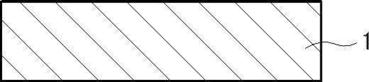
- FIG. 1 is a schematic cross-sectional view showing an example of a preferred embodiment of the aluminum foil of the present invention.
- FIG. 2 is a top view of the aluminum foil shown in FIG.
- oxide films 14 are formed on both main surfaces (maximum surfaces) of the aluminum base material 3.
- the oxide film is an aluminum oxide film containing an aluminum oxide such as aluminum oxide (Al 2 O 3 ).
- the aluminum foil 10 has a plurality of through holes 5 that penetrate the aluminum base material 3 and the oxide film 14 in the thickness direction. That is, the aluminum foil 10 has a structure in which an aluminum base material 3 having a through hole penetrating in the thickness direction and an oxide film 14 having a through hole penetrating in the thickness direction are laminated.
- the oxide film 14 is formed on both main surfaces of the aluminum base material 3, but the present invention is not limited to this, and the oxide film 14 is formed only on one main surface. There may be.
- the aluminum foil of the present invention is used as a current collector, and an active material (electrode material) is applied to the surface thereof to be used as a positive electrode or a negative electrode of a power storage device.
- an active material electrode material
- the aluminum foil has a plurality of through holes penetrating in the thickness direction, the movement of lithium ions can be facilitated when used as a current collector. Further, by having a large number of through holes, the adhesion to the active material can be improved.
- the oxide film 14 has a large number of granular intermetallic compounds 16 dispersed in the film.
- the intermetallic compound 16 has an elemental ratio O / Al of oxygen to aluminum of 2 or more and 4 or less.
- the density of the intermetallic compound 16 is 500 pieces / mm 2 or more.
- oxide film has high insulating properties, there is a problem that the presence of a thick oxide film on the surface of the aluminum base material may increase the electrical resistance between the aluminum base material and the active material.
- the oxide film 14 has a large number of granular intermetallic compounds dispersed in the film.
- the intermetallic compound has an element ratio O / Al of oxygen to aluminum of 2 or more and 4 or less.
- the density of the intermetallic compound is 500 pieces / mm 2 or more. According to the study by the present inventor, it has been found that an intermetallic compound having an element ratio O / Al of 2 or more and 4 or less serves as a starting point for lowering the insulating property in the oxide film.
- the insulating property of the oxide film can be lowered and the electrical resistance of the oxide film can be lowered.
- the method for forming an oxide film having an intermetallic compound having an element ratio O / Al of 2 or more and 4 or less at a density of 500 pieces / mm 2 or more will be described in detail later.
- the intermetallic compound in the present invention is a compound containing an aluminum element (Al) and at least one selected from Fe, Si, Mn, Mg, Ti, B and the like.
- the intermetallic compound include Al 3 Fe, Al 6 Fe, ⁇ AlFeSi, AlFeMnSi, Mg 2 Si, and TiB 2 .
- the intermetallic compound containing Al contains Al, so that a natural oxide film of aluminum is formed on the surface. Therefore, the surface layer of the intermetallic compound containing Al contains an oxygen element (O).
- the oxide film on the surface of the intermetallic compound has an intermetallic compound having an oxide film having an element ratio O / Al of 2 or more and 4 or less at a density of 500 pieces / mm 2 or more. Therefore, the oxide film on the outermost layer may have an intermetallic compound other than the element ratio O / Al of 2 or more and 4 or less. That is, the oxide film on the outermost layer may have an intermetallic compound having an element ratio O / Al of less than 2 or more than 4.
- an intermetallic compound having an element ratio O / Al of 2 or more and 4 or less in the oxide film of the outermost layer is referred to as an intermetallic compound A, and similarly, an element ratio O / Al in the oxide film of the outermost layer is less than 2.
- an intermetallic compound A an intermetallic compound having an element ratio O / Al of 2 or more and 4 or less in the oxide film of the outermost layer is referred to as an intermetallic compound A
- an element ratio O / Al in the oxide film of the outermost layer is less than 2.
- metal-metal compound B or more than 4 metal-metal compounds.
- the element ratio O / Al in the portion of the oxide film other than the intermetallic compound is less than 2. It is about 3 to 1.5.
- the average value of the element ratio O / Al of the oxide film on the surface layer of the intermetallic compound A is preferably 2 or more and 4 or less, and 2.5 or more and 3. It is more preferably 5 or less.
- the element ratio O / Al of the outermost layer of the intermetallic compound is measured as follows.
- SEM high-resolution scanning electron microscope
- the intermetallic compound (intermetallic compound A and the intermetallic compound B) is combined with a portion of the oxide film other than the intermetallic compound. It can be visually recognized separately (see FIGS. 8 and 13). Therefore, first, from the surface of the oxide film, the surface of the oxide film is photographed at a magnification of 5000 times using a high-resolution scanning electron microscope (SEM), and in the obtained SEM photograph, at least the intermetallic compound is contained. Extract 20 pieces.
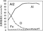
- elemental analysis is performed at the position of the extracted intermetallic compound from the outermost surface in the depth direction using field emission Auger electron spectroscopy (FE-AES). Analysis in the depth direction is performed by repeating measurement and surface removal by sputtering. From the result of the element distribution in the depth direction by FE-AES (see FIG. 9 and the like), the element ratio O / Al in the outermost layer is obtained.
- FE-AES field emission Auger electron spectroscopy
- the density of the intermetallic compound A is preferably 1000 pieces / mm 2 to 300,000 pieces / mm 2, and more preferably 5000 pieces / mm 2 to 200,000 pieces / mm 2. ..
- the density of the intermetallic compound A is measured as follows. First, the surface of the aluminum foil was photographed from directly above at a magnification of 5000 times using a high-resolution scanning electron microscope (SEM), and the 1.2 mm ⁇ 1.2 mm field of view (5 locations) of the obtained SEM photograph was taken. Extract the intermetallic compound. Next, the element ratio O / Al of each intermetallic compound extracted by elemental analysis using FE-AES is determined. The number of intermetallic compounds A having an element ratio O / Al of 2 or more and 4 or less is counted, and the number density is calculated from the number of intermetallic compounds A in the visual field and the area of the visual field (geometric area). The average value of the five visual fields is calculated as the density.
- SEM high-resolution scanning electron microscope
- the diameter equivalent to the circle of the intermetallic compound A is preferably 1 ⁇ m or less.
- Intermetallic compounds having a circle-equivalent diameter of 1 ⁇ m or less are easily exposed on the surface of the aluminum foil.
- the surface area of the intermetallic compound with respect to the volume increases.
- the element ratio O / Al of the oxidized intermetallic compound tends to be 2 or more.
- the equivalent circle diameter of the intermetallic compound A at least 20 intermetallic compounds A whose element ratio O / Al was measured as described above were extracted, and the surface of the oxide film of the intermetallic compound A was prepared by image analysis software or the like. The area is obtained, the circle-equivalent diameter is obtained from this area, and the average value of these is calculated as the circle-equivalent diameter.
- the oxide film on the outermost layer preferably contains 70% by mass or more of aluminum oxide (Al 2 O 3 ), more preferably 80% by mass to 100% by mass, and further preferably 90% by mass to 100% by mass. ..
- Al 2 O 3 aluminum oxide
- the oxide film on the outermost layer preferably contains 70% by mass or more of aluminum oxide (Al 2 O 3 ), more preferably 80% by mass to 100% by mass, and further preferably 90% by mass to 100% by mass. ..
- the ratio of aluminum oxide (Al 2 O 3 ) in the oxide film can be calculated by measuring the film density of the oxide film as follows.
- the film density of the oxide film is measured using a high resolution RBS analyzer HRBS500 (High Resolution Rutherford Backscattering Spectrometry; HR-RBS) manufactured by Kobe Steel, Ltd.
- HRBS500 High Resolution Rutherford Backscattering Spectrometry; HR-RBS
- He + ions with an energy of 450 keV are incident on the sample at 62.5 degrees with respect to the normal of the sample surface (the surface of the oxide film of the aluminum member for electrodes), and the scattered He + ions are deflected at a position of a scattering angle of 55 degrees.
- the surface density is obtained by detecting with an energy analyzer.
- the obtained surface density (atoms / cm 2 ) is converted to mass surface density (g / cm 2 ), and the density of the oxide film (g / cm 3 ) is calculated from this value and the film thickness measured by a transmission electron microscope (TEM). ) Is calculated.
- the oxide film of aluminum consists of non-hydrated aluminum oxide and hydrated aluminum oxide (monohydrate and trihydrate exist), and the hydrate density is convenient because the hydrates have different densities. Therefore, the average of monohydrate and trihydrate is taken, and the weighted average of the density of non-hydrate is considered to be the density obtained above, and the ratio of non-hydrate aluminum oxide is obtained from it.
- the thickness of the oxide film is preferably 5 nm or less, more preferably 4.5 nm or less, still more preferably 4 nm or less.
- the average opening diameter of the through hole is preferably 0.1 ⁇ m or more and less than 100 ⁇ m, more preferably more than 1 ⁇ m and 80 ⁇ m or less, further preferably more than 3 ⁇ m and 40 ⁇ m or less, and particularly preferably 5 ⁇ m or more and 30 ⁇ m or less.
- the average opening diameter of the through holes was obtained by photographing the surface of the aluminum foil from one surface of the aluminum foil at a magnification of 200 times using a high-resolution scanning electron microscope (SEM). In the photograph, at least 20 through holes having a ring-shaped periphery are extracted, the opening diameters thereof are read, and the average value of these is calculated as the average opening diameter. For the opening diameter, the maximum value of the distance between the ends of the through hole portion was measured. That is, since the shape of the opening of the through hole is not limited to a substantially circular shape, when the shape of the opening is non-circular, the maximum value of the distance between the ends of the through hole portion is set as the opening diameter. Therefore, for example, even in the case of a through hole having a shape in which two or more through holes are integrated, this is regarded as one through hole, and the maximum value of the distance between the ends of the through hole portion is set as the opening diameter. ..
- the average opening ratio of the through holes is preferably 0.5% to 30%, more preferably 1% to 30%, further preferably 2% to 20%, and particularly preferably 3% to 10%.
- the average aperture ratio of the through holes was obtained by photographing the surface of the aluminum foil from directly above at a magnification of 200 times using a high-resolution scanning electron microscope (SEM), and a field of view (5) of 30 mm ⁇ 30 mm in the obtained SEM photograph. (Location) is binarized with image analysis software, etc., and the through-hole portion and non-through-hole portion are observed, and the ratio of the total aperture area of the through-hole to the visual field area (geometric area) (aperture area / geometry). It was calculated from the scientific area), and the average value in each visual field (5 points) was calculated as the average aperture ratio.
- SEM scanning electron microscope
- the aluminum foil preferably has a non-penetrating recess having an average opening diameter of 0.1 ⁇ m to 100 ⁇ m on the surface (oxide film).
- the occupancy rate (area ratio) of the recesses on the surface of the aluminum foil is preferably 1% or more.
- the average opening diameter of the recess is preferably 0.1 ⁇ m to 100 ⁇ m, more preferably 1 ⁇ m to 50 ⁇ m, and even more preferably 2 ⁇ m to 30 ⁇ m.
- the average opening diameter of the recess is determined by photographing the surface of the aluminum foil from one surface of the aluminum foil with a high-resolution scanning electron microscope (SEM) at a magnification of 200 times from directly above. At least 20 recesses (pits) having a concavo-convex structure in which the periphery is circularly connected were extracted, the maximum diameter thereof was read and used as the opening diameter, and the average value thereof was calculated as the average opening diameter.
- the maximum diameter is the maximum value of the linear distance between one edge constituting the opening of the recess.
- the recess is circular, it means the diameter, if the recess is elliptical, it means the major axis, and if the recess has a shape in which multiple circles overlap, the edge of one circle and the other circle.
- the occupancy rate of the concave portion is preferably 1% or more, more preferably 2% to 5%, and more preferably 5% to 10%.
- the occupancy of the recesses was determined by photographing the surface of the aluminum foil from directly above at a magnification of 200 times using a high-resolution scanning electron microscope (SEM), and a field of view (5 locations) of 30 mm ⁇ 30 mm in the obtained SEM photograph.
- the ratio (opening area / geometric area) between the total opening area of the concave portion and the area of the visual field (geometric area) is calculated by quantifying the image with image analysis software or the like and observing the concave portion and the non-recessed portion. It was calculated, and the average value in each field of view (5 points) was calculated as the occupancy rate.
- the water contact angle of the surface of the aluminum foil is preferably 20 ° to 80 °.
- the aluminum foil used as a current collector is used as an electrode by applying an electrode material on the surface.
- the electrode material is applied to the current collector by making an aqueous solvent into a slurry.
- the surface is hydrophilized to make it hydrophilic (that is, to reduce the water contact angle) in order to prevent the electrode material from being repelled and improve the coatability. ) Is being carried out (for example, International Publication No. 2011/089722).
- the water contact angle of the surface of the aluminum foil (the surface of the oxide film) is preferably 40 ° or more, and more preferably 50 ° or more.
- the water contact angle of the surface of the aluminum foil is too high, when the water-based electrode material is applied, it may be repelled by the surface and a problem may occur in which uniform application cannot be performed.
- the coatability of the electrode material can be improved.
- the water contact angle of the surface of the aluminum foil (the surface of the oxide film) is preferably 70 ° or less.
- the water contact angle is measured by the sessile drop method in which water droplets are attached in the air to determine the water contact angle.
- the static contact angle is good as the method for measuring the water contact angle, and the sessile drop method can be used in the case of the method for measuring the static contact angle.
- the static drip method described in "JIS R 3257: 1999 Wetting property test method for substrate glass surface” can be used for measuring the water contact angle.
- the water contact angle can be measured by, for example, a portable contact angle meter PCA-1 (Kyowa Interface Science Co., Ltd.).
- the aluminum base material used as the base material of the aluminum foil is not particularly limited, and for example, known aluminum base materials such as alloy numbers 1N30 and 3003 described in JIS standard H4000 can be used. Aluminum containing a large amount of intermetallic compounds is preferable, but the present application is not limited to aluminum materials.
- the aluminum base material is an alloy plate containing aluminum as a main component and containing a trace amount of foreign elements.
- the aluminum base material is made of metal. It is preferable to have 500 elements / mm 2 or more, more preferably 1000 elements / mm 2 or more and 200,000 elements / mm 2 or less, and further preferably 3000 elements / mm 2 or more and 300,000 elements / mm 2 or less.
- the circle-equivalent diameter of the intermetallic compound having an element ratio O / Al of 2 or more and 4 or less contained in the aluminum base material is preferably 1 ⁇ m or less.
- the thickness of the aluminum base material is not limited, but is preferably 5 ⁇ m to 100 ⁇ m, and more preferably 10 ⁇ m to 30 ⁇ m.
- the method for producing an aluminum foil of the present invention is Through hole forming step to form through hole and An alkaline treatment step in which the aluminum base material after the film forming step is brought into contact with an alkaline aqueous solution to dissolve the outermost surface, It has an acid treatment step of contacting the aluminum base material after the alkali treatment step with an acidic aqueous solution to remove the residue on the surface of the aluminum base material and to make the natural oxide film formed after that into a passivation.
- This is a method for manufacturing an aluminum foil.
- a film mainly composed of aluminum oxide having an element ratio of 1 to 2 is formed on most of the surface of the aluminum base material, while the surface of the intermetallic compound has an element ratio of O / Al of 2.
- An oxide film of 4 or more is formed.
- a film mainly composed of aluminum oxide having a majority element ratio O / Al of 1 to 2 on the surface of the aluminum base material is formed.
- an oxide film having an element ratio O / Al of 2 or more and 4 or less can be preferably formed on the surface of the intermetallic compound.
- the alkali treatment step removes unnecessary film, oil, etc. before the acid treatment step, exposes the aluminum base material, and facilitates the formation of an oxide film.
- the through hole forming step a known method such as a method using electrolysis or a method of mechanically forming a hole can be applied.
- the drying step after the water washing step after the acid treatment step is preferably performed by using a high temperature air of more than 200 ° C. and 350 ° C. or lower on the aluminum base material.
- the element ratio O / Al of most of the oxide films of the aluminum base material becomes 1 or more and less than 2, and the element ratio O / Al is on the surface of the intermetallic compound. It is preferable that an oxide film having a value of 2 or more and 4 or less is easily formed.
- FIGS. 3 to 6 are schematic cross-sectional views showing an example of a preferred embodiment of the method for producing an aluminum foil.
- the method for producing an aluminum foil is a film forming step (FIG. 3) in which both main surfaces of the aluminum base material 1 are subjected to a film forming treatment to form a film 2 such as aluminum hydroxide. 3 and FIG. 4) and a through hole forming step (FIG. 4) in which an electrolytic dissolution treatment is performed after the film forming step to form a through hole 5, and an aluminum base material 3 having a through hole and a film 4 having a through hole are formed.
- FIG. 5 an alkali treatment step step (FIGS.
- This is a production method comprising an acid treatment step (FIGS. 6 and 1) of forming an oxide film on both main surfaces of the aluminum base material 3 having through holes.
- the through hole forming step is a step of forming a through hole in the aluminum base material.
- the method for forming the through hole in the through hole forming step is not particularly limited, and a mechanical method such as punching or an electrochemical method such as electrolytic dissolution treatment can be used.
- a method for forming a through hole by an electrolytic dissolution treatment is preferable because a through hole having an average opening diameter of 0.1 ⁇ m to 100 ⁇ m can be easily formed.
- the through-hole forming step of performing the electrolytic dissolution treatment after the film forming step of forming an inhomogeneous film in advance, the aluminum base material is used as an anode and the electrolytic treatment (electrolytic dissolution treatment) is performed with a third acidic aqueous solution to form an aluminum base.
- This is a step of forming through holes in the material and the aluminum hydroxide film.
- the type of film is not particularly limited as long as it can form a difference between a place where it dissolves during electrolytic treatment and easily penetrates and a place where it does not easily penetrate.
- the electrolytic dissolution treatment is not particularly limited, and an acidic solution (second acidic aqueous solution) can be used as the electrolytic solution by using direct current or alternating current.
- an acidic solution second acidic aqueous solution
- the concentration of the acidic solution is preferably 0.1 to 2.5% by mass, and particularly preferably 0.2 to 2.0% by mass.
- the temperature of the acidic solution is preferably 20 to 80 ° C, more preferably 30 to 60 ° C.
- the acid-based aqueous solution is an acid aqueous solution having a concentration of 1 to 100 g / L and a nitrate compound having nitrate ions such as aluminum nitrate, sodium nitrate and ammonium nitrate, or hydrochloric acid such as aluminum chloride, sodium chloride and ammonium chloride.
- a hydrochloric acid compound having an ion and a sulfate compound having a sulfate ion such as aluminum sulfate, sodium sulfate and ammonium sulfate can be added and used in a range from 1 g / L to saturation.
- the metal contained in the aluminum alloy such as iron, copper, manganese, nickel, titanium, magnesium and silica may be dissolved in the aqueous solution mainly containing an acid. It is preferable to use a solution obtained by adding aluminum chloride, aluminum nitrate, aluminum sulfate or the like to an aqueous solution having an acid concentration of 0.1 to 2% by mass so that aluminum ions are 1 to 100 g / L.
- a direct current is mainly used for the electrochemical dissolution treatment, but when an alternating current is used, the alternating current power wave is not particularly limited, and a sine wave, a square wave, a trapezoidal wave, a triangular wave, etc. are used. Of these, a square wave or a trapezoidal wave is preferable, and a trapezoidal wave is particularly preferable.
- nitric acid electrolysis In the present invention, through holes having an average opening diameter of 0.1 ⁇ m to 100 ⁇ m can be easily formed by an electrochemical dissolution treatment (hereinafter, also abbreviated as “nitric acid dissolution treatment”) using an electrolytic solution mainly containing nitric acid. Can be formed.
- nitric acid dissolution treatment a direct current is used, the average current density is 5 A / dm 2 or more, and the amount of electricity is 50 C / dm 2 or more because it is easy to control the dissolution point of the through hole formation. It is preferable that the electrolytic treatment is performed in 1.
- the average current density is preferably 100 A / dm 2 or less, and the amount of electricity is preferably 10000 C / dm 2 or less.
- the concentration and temperature of the electrolytic solution in nitric acid electrolysis are not particularly limited, and electrolysis can be performed at a high concentration, for example, a nitric acid electrolytic solution having a nitric acid concentration of 15 to 35% by mass at 30 to 60 ° C., or a nitric acid concentration of 0. Electrolysis can be performed at a high temperature, for example, 80 ° C. or higher, using a nitric acid electrolytic solution of 7 to 2% by mass. Further, electrolysis can be performed using an electrolytic solution in which at least one of sulfuric acid, oxalic acid and phosphoric acid having a concentration of 0.1 to 50% by mass is mixed with the nitric acid electrolytic solution.
- a through hole having an average opening diameter of 0.1 ⁇ m to 100 ⁇ m can be easily obtained by an electrochemical dissolution treatment using an electrolytic solution mainly containing hydrochloric acid (hereinafter, also abbreviated as “hydrochloric acid dissolution treatment”).
- hydrochloric acid dissolution treatment a direct current is used, the average current density is 5 A / dm 2 or more, and the amount of electricity is 50 C / dm 2 or more because it is easy to control the dissolution point of the through hole formation. It is preferable that the electrolytic treatment is performed in 1.
- the average current density is preferably 100 A / dm 2 or less, and the amount of electricity is preferably 10000 C / dm 2 or less.
- the concentration and temperature of the electrolytic solution in hydrochloric acid electrolysis are not particularly limited, and electrolysis may be performed at a high concentration, for example, a hydrochloric acid electrolytic solution having a hydrochloric acid concentration of 10 to 35% by mass at 30 to 60 ° C., or a hydrochloric acid concentration of 0. Electrolysis can be performed at a high temperature, for example, 80 ° C. or higher, using a hydrochloric acid electrolytic solution of 7 to 2% by mass. Further, electrolysis can be performed using an electrolytic solution in which at least one of sulfuric acid, oxalic acid and phosphoric acid having a concentration of 0.1 to 50% by mass is mixed with the hydrochloric acid electrolytic solution.
- the alkaline treatment step is a step of dissolving (removing) the outermost layer of the aluminum base material by performing a chemical dissolution treatment using an alkaline aqueous solution.
- the residue and film remaining on the surface when through holes are formed by electrolytic treatment are temporarily removed.
- the intermetallic compound on the surface layer of the aluminum base material has a slower dissolution rate in the alkaline aqueous solution than the aluminum base material, the intermetallic compound slightly emerged on the surface layer of the aluminum base material by appropriately selecting the treatment conditions. Can be left on the surface in the state.
- the outermost layer of the aluminum base material can be dissolved (removed) by performing an alkali etching treatment described later.
- the alkaline etching treatment is a treatment for dissolving the surface layer by bringing the aluminum base material into contact with an alkaline aqueous solution.
- alkali used in the alkaline aqueous solution examples include Kasei alkali and alkali metal salts.
- examples of the caustic alkali include sodium hydroxide (caustic soda) and caustic potash.
- alkali metal salt examples include alkali metal silicates such as sodium metasilicate, sodium silicate, potassium metasilicate and potassium silicate; alkali metal carbonates such as sodium carbonate and potassium carbonate; sodium aluminate and aluminen.
- Alkali metal aluminates such as potassium acid; alkali metal aldonates such as sodium gluconate and potassium gluconate; sodium diphosphate, potassium diphosphate, sodium triphosphate, potassium ternate, etc.
- Examples include alkali metal hydrogen phosphate.
- a solution of Kasei alkali and a solution containing both Kasei alkali and alkali metal aluminate are preferable from the viewpoint of high etching rate and low cost.
- an aqueous solution of sodium hydroxide is preferable.
- the concentration of the alkaline aqueous solution is preferably 0.1 to 50% by mass, more preferably 0.2 to 10% by mass.
- the concentration of the aluminum ions is preferably 0.01 to 10% by mass, more preferably 0.1 to 3% by mass.
- the temperature of the alkaline solution is preferably 10 to 90 ° C.
- the processing time is preferably 1 to 120 seconds.
- Examples of the method of bringing the aluminum base material into contact with the alkaline solution include a method of passing the aluminum base material through a tank containing an alkaline solution, a method of immersing the aluminum base material in a tank containing an alkaline solution, and an alkali.
- a method of spraying the solution onto the surface of the aluminum base material can be mentioned.
- the aluminum base material is brought into contact with an acidic aqueous solution (first acidic aqueous solution) to form an oxide film having an element ratio O / Al of 1 or more and less than 2 on the front surface or the back surface of the aluminum base material.
- This is a step of forming an oxide film having an element ratio O / Al of 2 or more and 4 or less on the surface of the intercompound.
- an oxide film having an element ratio O / Al of 1 or more and less than 2 is formed on most of the surface of the aluminum base material, and an element ratio O / is formed on the surface of an intermetallic compound having 500 elements / mm 2 or more.
- the surface of the aluminum base material is washed away with an acidic aqueous solution to remove the residue formed in the alkali treatment step, and the natural oxide film formed on the surface of the aluminum base material is mainly composed of aluminum oxide. It can be made into a passivation film.
- the intermetallic compound composed of aluminum and Fe, Si, etc. contained in the aluminum base material contains an aluminum element, an oxide film is formed.
- the intermetallic compound is slightly raised on the surface layer of the aluminum base material by the alkali treatment step, the ratio of the exposed area to the volume of the intermetallic compound becomes large. ..
- the acidic aqueous solution (first acidic aqueous solution) used in the acid treatment step it is preferable to use nitric acid, sulfuric acid, phosphoric acid, oxalic acid, or a mixed acid of two or more of these, and it is more preferable to use an acidic aqueous solution containing nitric acid. preferable.
- the concentration of the acidic aqueous solution is preferably 0.01 to 10% by mass, and particularly preferably 0.1 to 5% by mass.
- the temperature of the acidic aqueous solution is preferably 25 to 70 ° C, more preferably 30 to 55 ° C.
- the method of bringing the aluminum base material into contact with the acidic aqueous solution is not particularly limited, and examples thereof include a dipping method and a spraying method.
- the spray method is preferable because it is easy to replace the liquid on the aluminum surface.
- the dipping method is a process of immersing the aluminum base material in the above-mentioned acidic solution. It is preferable to stir during the dipping treatment because the treatment is even.
- the time of the dipping treatment is preferably 15 seconds or more, more preferably 30 seconds or more, and further preferably 40 seconds or more.
- drying process As described above, it is preferable to have a drying step of performing a drying treatment after the washing step of each step.
- the drying method is not limited, and known drying methods such as a method of blowing off moisture with an air knife or the like and a method of heating can be appropriately used. Moreover, you may perform a plurality of drying methods.
- the drying step is preferably a step of applying hot air of more than 200 ° C. and 350 ° C. or lower to the surface of the aluminum base material to heat it.
- a water washing step is performed to remove the acidic aqueous solution remaining on the surface of the aluminum base material (oxide film), and further, the water film adhered in the water washing step is performed.
- an oxide film having an element ratio O / Al of 1 or more and less than 2 is formed on the surface of the aluminum base material, and the metal-to-metal compound is formed.
- An oxide film having an element ratio O / Al of 2 or more and 4 or less can be preferably formed on the surface of the above.
- the heating temperature in the drying step after the acid treatment step is preferably 180 ° C. to 350 ° C., more preferably 240 ° C. to 300 ° C.
- the drying time is preferably 1 to 30 seconds, more preferably 3 to 10 seconds.
- the water contact angle of the surface of the aluminum foil (surface of the oxide film) produced by the production method of the present invention is affected by the method of forming through holes. Therefore, a step of adjusting the water contact angle may be carried out according to the water contact angle of the surface of the aluminum foil (the surface of the oxide film) after the production (after the acid treatment step).
- the water contact angle of the surface of the aluminum foil (surface of the oxide film) after production (after the acid treatment step) is 20 ° to 80 °, it becomes hydrophilic after the formation of the oxide film (after the acid treatment step). It is preferable not to carry out the chemical treatment. Further, it is preferable that the hydrophilization treatment is not performed between the production of the aluminum foil and the application of the electrode material.
- the aluminum foil of the present invention can be used as a current collector for a power storage device (hereinafter, also referred to as a “current collector”). Since the aluminum foil has a plurality of through holes in the thickness direction of the current collector, for example, when it is used for a lithium ion capacitor, lithium can be pre-doped in a short time, and lithium can be more uniformly dispersed. It becomes possible to disperse. In addition, the adhesion to the active material layer and activated carbon is improved, and a power storage device having excellent productivity such as cycle characteristics, output characteristics, and coating suitability can be manufactured. Further, in the current collector using the aluminum foil of the present invention, since the electric resistance of the oxide film is low, the electric resistance with the active material layer is low, and an efficient power storage device can be manufactured.
- the active material layer is not particularly limited, and a known active material layer used in a conventional power storage device can be used.
- the conductive material, the binder, the solvent and the like which may be contained in the active material and the active material layer are described in JP-A-2012-216513.
- the materials described in paragraphs [0077] to [0088] of the above can be appropriately adopted, and the contents thereof are incorporated herein by reference.
- the aluminum foil is used as the current collector of the negative electrode
- the material described in paragraph [089] of JP2012-216513A can be appropriately adopted as the active material, and the contents thereof are described in the present specification. Incorporated as a reference in the book.
- the electrode using the aluminum foil of the present invention as a current collector can be used as a positive electrode or a negative electrode of a power storage device such as a lithium ion battery or a lithium ion capacitor.
- a power storage device such as a lithium ion battery or a lithium ion capacitor.
- the materials and uses described in paragraphs [0090] to [0123] of JP2012-216513A can be appropriately used. It can be adopted and its contents are incorporated herein by reference.
- the positive electrode using the aluminum foil of the present invention as a current collector is a layer containing a positive electrode current collector using an aluminum foil as a positive electrode and a positive electrode active material formed on the surface of the positive electrode current collector (positive electrode active material layer). It is a positive electrode having and.
- the positive electrode active material, the conductive material, the binder, the solvent and the like which may be contained in the positive electrode active material layer are described in paragraphs [0077] to [0088] of JP2012-216513A. The materials described may be employed as appropriate and their contents are incorporated herein by reference.
- the negative electrode using the aluminum foil of the present invention as the current collector is a negative electrode having a negative electrode current collector using the aluminum foil as the negative electrode and a layer containing a negative electrode active material formed on the surface of the negative electrode current collector. ..
- the negative electrode active material the material described in paragraph [089] of JP2012-216513A can be appropriately adopted, and the content thereof is incorporated as a reference in the present specification.
- the aluminum foil of the present invention can also be used as a current collector for an electrolytic capacitor.
- Example 1 and 2 and Comparative Examples 1 to 3 ⁇ Preparation of aluminum base material> Aluminum substrates A1 and A2 containing an intermetallic compound having a circle-equivalent diameter of 1 ⁇ m or less and an aluminum substrate B containing no intermetallic compound having a circle-equivalent diameter of 1 ⁇ m or less were prepared.
- the aluminum base material A1 is made by melting an aluminum ingot with an Al purity of 99.90%, casting aluminum with 2% Fe added by a DC (Direct Chill) casting method, and then performing hot rolling and cold rolling to achieve the final thickness. It is an aluminum base material finished to 20 ⁇ m. In order to adjust the strength, heat treatment was performed during cold rolling when the plate thickness was 2 mm.
- the aluminum base material A2 is an aluminum base obtained by melting an aluminum base metal having an Al purity of 99.90%, casting aluminum with 0.5% Fe added by a continuous casting method, and then cold rolling to a final plate thickness of 20 ⁇ m. It is a material. In order to adjust the strength, heat treatment was performed during cold rolling when the plate thickness was 2 mm.
- the aluminum base material B is made of aluminum having an Al purity of 99.90% cast by a DC casting method and then hot-rolled and cold-rolled to a final plate thickness of 20 ⁇ m in the same manner as the aluminum base material A1. It is a base material.
- Each aluminum base material was subjected to the through hole forming treatment 1 and / or the through hole forming treatment 2 shown below to form a through hole.
- A-1 Inhomogeneous film forming step
- electrolysis was performed with an acidic solution containing aluminum ions in the liquid to precipitate aluminum hydroxide having a thickness of 1 ⁇ m or more. This becomes a heterogeneous film.
- Electrolytic dissolution treatment (through hole forming step) Next, using an electrolytic solution kept at 50 ° C. (nitric acid concentration 2%, sulfuric acid concentration 2%, aluminum concentration 1%), electrolytic treatment was performed using an aluminum base material as an anode to obtain an aluminum base material and an aluminum hydroxide film. A through hole was formed. The electrolytic treatment was performed with a DC power supply. The current density was adjusted so that the aperture ratio was about 4%. After forming the through hole, it was washed with water by spraying.
- an aqueous solution liquid temperature 37 ° C.
- (D-1) Acid Treatment Step the aluminum base material after the alkali treatment step is sprayed with an aqueous solution (liquid temperature 50 ° C.) having a nitric acid concentration of 10% and an aluminum ion concentration of 5% by mass for 5 seconds on the surface of the aluminum base material. An oxide film was formed on the aluminum. Then, it was washed with water by spraying.
- aqueous solution liquid temperature 50 ° C.
- the through holes formed in the through hole forming process 1 are generally formed with an aperture ratio of 4.0%, an average hole diameter of 10 ⁇ m, and a density of 100 holes / mm 2 .
- Table 1 shows the types of the aluminum base material and the types of through-hole forming treatment used in each Example and Comparative Example.
- the aluminum foils produced in each Example and Comparative Example are stored in an environment of temperature 30 ° C. and humidity 80%, and the resistances after 1 week, 2 weeks, 3 weeks and 4 weeks are measured by the above resistance value measuring method, respectively. It was measured.
- the forced aging resistance is A if the resistance value after holding for 4 weeks is within 50 m ⁇ , within 50 m ⁇ after holding for 3 weeks, B if it exceeds 50 m ⁇ after holding for 4 weeks, and within 50 m ⁇ after holding for 2 weeks, after holding for 3 weeks. If it exceeds 50 m ⁇ , it is judged as C, and if it exceeds 50 m ⁇ after holding for 2 weeks, it is judged as D.
- Table 1 The results are shown in Table 1.
- Example 1 the surface (surface of the oxide film) of the portion where the through hole is not formed in Example 1 and Comparative Example 3 is observed by SEM using FE-AES (manufactured by JEOL Ltd.), and the oxide film on the surface is observed. The result of element distribution from the outermost surface to the depth direction is illustrated.
- FIG. 8 shows an example of the SEM image of Example 1.
- the oxide film has a large number of granular intermetallic compounds.
- the intermetallic compounds are indicated as IMC1 and IMC2, and the portions other than the intermetallic compounds are indicated as A11 and A12.
- FIG. 9 to 12 show the results of elemental analysis of the parts of IMC1, IMC2, A11 and A12 in FIG. 8 in the depth direction, respectively.
- FIG. 9 shows the result of elemental analysis of the part of IMC1.
- This intermetallic compound had a circle-equivalent diameter of 3 ⁇ m or more.
- FIG. 10 shows the result of elemental analysis of the part of IMC2.
- This intermetallic compound had a circle-equivalent diameter of 1 ⁇ m or less.
- FIG. 11 shows the result of elemental analysis of the Al1 portion.
- FIG. 12 shows the result of elemental analysis of the Al2 portion.
- the element ratio O / Al of the outermost layer in the portion of IMC1 in FIG. 9, the portion of Al1 in FIG. 11 and the portion of Al2 in FIG. 12 is 2 or less.
- the element ratio O / Al of the outermost layer in the portion of IMC2 in FIG. 10 is 2 or more and 4 or less. That is, in the example of the SEM image shown in FIG. 8, the portion of IMC1 corresponds to the intermetallic compound B, and the portion of IMC2 corresponds to the intermetallic compound A.
- the density of the intermetallic compound A was determined by the above-mentioned method by performing such elemental analysis, it was 110,000 pieces / mm 2 .
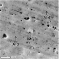
- FIG. 13 shows an example of the SEM image of Comparative Example 3.
- the oxide film has a granular intermetallic compound.
- the intermetallic compound was indicated as IMC3, and the portions other than the intermetallic compound were indicated as A13 and A14.
- FIGS. 14 to 16 The results of elemental analysis of the parts of IMC3, A13 and A14 in FIG. 13 in the depth direction are shown in FIGS. 14 to 16.
- FIG. 14 shows the result of elemental analysis of the part of IMC3. This intermetallic compound had a circle-equivalent diameter of 1 ⁇ m or more.
- FIG. 15 shows the result of elemental analysis of the Al3 portion.
- FIG. 16 shows the result of elemental analysis of the Al4 portion.
- the element ratio O / Al of the outermost layer in the portion of IMC3 in FIG. 14, the portion of Al3 in FIG. 15, and the portion of Al4 in FIG. 16 is 2 or less. That is, in the example of the SEM image shown in FIG. 13, the portion of IMC3 corresponds to the intermetallic compound B. From Comparative Example 3, the intermetallic compound A having an element ratio O / Al of 2 or more and 4 or less in the outermost layer could not be observed. The results of elemental analysis are shown in Table 2.
- the aluminum foil of the present invention having an oxide film having 500 intermetallic compounds A having an element ratio O / Al of 2 or more and 4 or less / mm 2 or more has an initial resistance as compared with a comparative example. And it can be seen that the resistance over time is low.
- Comparative Examples 4 and 5 Aluminum foils were made using the methods described in Example 5 and Example 11 of International Publication No. 2017/018462, respectively. Comparative Example 4 is an example in which an aluminum base material containing a small amount of small intermetallic compounds is used, and Comparative Example 5 is an example in which an aluminum base material containing a small intermetallic compound is used.
- Example 3 An aluminum foil was produced in the same manner as in Example 1 except that the treatment conditions of the through hole forming step were changed in order to obtain the same through hole physical properties (average opening diameter and average aperture ratio) as those of Comparative Examples 4 and 5. ..
- Comparative Example 4 and Comparative Example 5 differ in the type of aluminum base material, the type of acid used in the acid treatment step, and the temperature in the drying step.
- the intermetallic compound A was not observed in the oxide film as shown in Table 4.
- the element ratio O / Al of the intermetallic compound was 1.3 at the maximum.
- the element ratio O / Al of the intermetallic compound was 1.9 at the maximum.
- the element ratio O / Al of the intermetallic compound was 3.0 on average.
- Example 3 of the present invention although the initial film thickness of the oxide film is thick, it can be seen that the resistance value does not increase with time. This is done by using an aluminum base material containing a large amount of small intermetallic compounds as the aluminum base material and setting the element ratio O / Al of the small intermetallic compounds in the oxide film within a predetermined range, so that the intermetallic compound A can be obtained. This is because it becomes a conduction point and low resistance can be maintained.
- Comparative Example 6 An aluminum foil was prepared using the method described in Example 1 of International Publication No. 2018/062046. Comparative Example 6 is an example in which an aluminum base material containing a large amount of small intermetallic compounds is used.
- Example 4 An aluminum foil was produced in the same manner as in Example 1 except that the treatment conditions in the through hole forming step were changed in order to obtain the same through hole physical properties (average opening diameter and average aperture ratio) as in Comparative Example 6.
- Comparative Example 6 As shown in Table 5, in Comparative Example 6, the type of the aluminum base material, the type of the acid used in the acid treatment step, and the temperature in the drying step are different. In Comparative Example 6 in which the aluminum foil was prepared under such conditions, the intermetallic compound A was not observed in the oxide film as shown in Table 6. In Comparative Example 6, the element ratio O / Al of the intermetallic compound was 1.8 at the maximum. On the other hand, in Example 4, the element ratio O / Al of the intermetallic compound was 3.0 on average.
- Comparative Example 6 by controlling the film quality of the oxide film, it is possible to suppress the thickening of the oxide film over time and keep the film thickness thin, but the resistance value is high over a long period of time (8 weeks). There is an increase.
- Example 4 of the present invention it can be seen that the increase in film thickness of the oxide film with time is larger than that of Comparative Example, but the resistance value can be maintained low.
- the element ratio O / Al of the small intermetallic compound in the oxide film to a predetermined range, even if the thickness of the entire oxide film is increased, the intermetallic compound A becomes a conduction point and is low. This is because resistance can be maintained.
- Example 5 An aluminum foil was prepared in the same manner as in Example 2, and then washed with a solvent (MEK (methyl ethyl ketone)) to prepare an aluminum foil.
- MEK methyl ethyl ketone
- Example 6 An aluminum foil was prepared in the same manner as in Example 2, washed with a solvent (MEK (methyl ethyl ketone)), and then packed with untreated aluminum foil (A1085 material, untreated, unwashed) for one week. That is, the aluminum foil produced in the same manner as in Example 5 was packed with untreated aluminum foil for one week.
- a solvent MEK (methyl ethyl ketone)
- untreated aluminum foil A1085 material, untreated, unwashed
- Example 7 An aluminum foil was prepared in the same manner as in Example 2, and then packed with untreated aluminum foil for one week.
- Example 8 After producing an aluminum foil in the same manner as in Example 2, a corona treatment was performed once to make it hydrophilic to produce an aluminum foil.
- a processing device manufactured by Kasuga Electric Works Ltd. was used for the corona treatment. The output of corona processing was 600 W.
- Example 9 After producing an aluminum foil in the same manner as in Example 2, corona treatment was performed twice to make it hydrophilic to produce an aluminum foil.
- Example 10 An aluminum foil was prepared in the same manner as in Example 2, and then packed with untreated aluminum foil for 2 weeks.
- the water contact angle was measured for the aluminum foils of Examples 2 and 5 to 10.
- the water contact angle was measured using a portable contact angle meter PCA-1 (Kyowa Interface Science Co., Ltd.) according to the static drip method described in "JISR3257: 1999 Wetting property test method for substrate glass surface". ..
- the measurement conditions were as follows. Waiting time until measurement 2000ms Preparation liquid volume 1.8 ⁇ L
- the measurement results of the water contact angle are shown in Table 7.
- Example 10 is packaged and stored for a longer period of time than Example 8. In Example 10, since the packing storage period is long, the water contact angle is further increased and exceeds 80 °. As a result, the coatability of Example 10 became non-uniform as compared with other Examples.
- Example 10 the initial resistance and the forced aging resistance deteriorate when the water contact angle on the surface is less than 20 °.
- the surface was forcibly hydrolyzed by performing corona treatment. As described above, it can be seen that the resistance deteriorates when the water contact angle is lowered by performing the corona treatment. It is probable that in Example 10, since the coatability was non-uniform, the contact state between the electrode material and the aluminum foil was insufficient, and the initial resistance was worse than in Example 2.
- the forced time resistance of Example 10 was the same level as that of Example 2 without much deterioration because the water contact angle on the surface was large and the water repellency was close. From the above, the effect of the present invention is clear.
Landscapes
- Chemical & Material Sciences (AREA)
- Engineering & Computer Science (AREA)
- Materials Engineering (AREA)
- Power Engineering (AREA)
- Chemical Kinetics & Catalysis (AREA)
- General Chemical & Material Sciences (AREA)
- Microelectronics & Electronic Packaging (AREA)
- Mechanical Engineering (AREA)
- Metallurgy (AREA)
- Organic Chemistry (AREA)
- Electrochemistry (AREA)
- Manufacturing & Machinery (AREA)
- Cell Electrode Carriers And Collectors (AREA)
- Electric Double-Layer Capacitors Or The Like (AREA)
- Chemical Treatment Of Metals (AREA)
- Cleaning And De-Greasing Of Metallic Materials By Chemical Methods (AREA)
- Preventing Corrosion Or Incrustation Of Metals (AREA)
Abstract
Description
アルミニウム箔は、表面に酸化膜を有し、
酸化膜はアルミニウムに対する酸素の元素比率O/Alが2以上4以下である金属間化合物を有し、
金属間化合物の密度が500個/mm2以上であるアルミニウム箔。
[2] 金属間化合物の円相当直径が1μm以下である[1]に記載のアルミニウム箔。
[3] 酸化膜が酸化アルミニウムを70質量%以上含む[1]または[2]に記載のアルミニウム箔。
[4] 酸化膜の表面の接触角が20°~80°である[1]~[3]のいずれかに記載のアルミニウム箔。
[5] 貫通孔の平均開口径が0.1μm~100μmである[1]~[4]のいずれかに記載のアルミニウム箔。
[6] 平均開口径が0.1μm~100μmの貫通していない凹部を有し、
凹部の占有率が1%以上である[1]~[5]のいずれかに記載のアルミニウム箔。
[7] [1]~[6]のいずれかに記載のアルミニウム箔を製造するアルミニウム箔の製造方法であって、
アルミニウム基材に貫通孔を形成する貫通孔形成工程と、
アルミニウム基材をアルカリ性水溶液に接触させて最表層を溶解するアルカリ処理工程と、
前記アルカリ処理工程後の前記アルミニウム基材を酸性水溶液に接触させて、前記アルミニウム基材の表面に酸化膜を形成する酸処理工程と、を有するアルミニウム箔の製造方法。
[8] [1]~[6]のいずれかに記載のアルミニウム箔を用いた集電体。
[9] [8]に記載の集電体を用いたリチウムイオンキャパシタ。
[10] [8]に記載の集電体を用いたリチウムイオンバッテリー。
以下に記載する構成要件の説明は、本発明の代表的な実施態様に基づいてなされることがあるが、本発明はそのような実施態様に限定されるものではない。
なお、本明細書において、「~」を用いて表される数値範囲は、「~」の前後に記載される数値を下限値および上限値として含む範囲を意味する。
本発明のアルミニウム箔は、
厚さ方向に貫通する複数の貫通孔を有するアルミニウム箔であって、
アルミニウム箔は、表面に酸化膜を有し、
酸化膜はアルミニウムに対する酸素の元素比率O/Alが2以上4以下である金属間化合物を有し、
金属間化合物の密度が500個/mm2以上であるアルミニウム箔である。
次に、本発明のアルミニウム箔の構成について、図1および図2を用いて説明する。
図1に示すように、アルミニウム箔10は、アルミニウム基材3の両主面(最大面)それぞれに酸化膜14が形成されている。酸化膜は、酸化アルミニウム(Al2O3)等のアルミニウム酸化物を含有するアルミニウム酸化皮膜である。また、アルミニウム箔10は、アルミニウム基材3および酸化膜14を厚み方向に貫通する複数の貫通孔5を有する。すなわち、アルミニウム箔10は、厚み方向に貫通する貫通孔を有するアルミニウム基材3と、厚み方向に貫通する貫通孔を有する酸化膜14とを積層した構成を有する。
アルミニウム箔が、厚み方向に貫通する複数の貫通孔を有することで、集電体として用いる場合に、リチウムイオンの移動を容易にすることができる。また、多数の貫通孔を有することで、活物質との密着性を向上することができる。
本発明者の検討によれば、元素比率O/Alが2以上4以下の金属間化合物は、酸化膜において絶縁性を低下させる起点となることがわかった。絶縁性を低下させる起点となる金属間化合物を500個/mm2以上の密度で有することで、酸化膜の絶縁性を低下させて、酸化膜の電気抵抗を低下させることができる。
なお、元素比率O/Alが2以上4以下の金属間化合物を500個/mm2以上の密度で有する酸化膜を形成する方法については後に詳述する。
そのため、Alを含む金属間化合物の表層は酸素元素(O)を含む。
以下の説明では、最表層の酸化膜中の元素比率O/Alが2以上4以下の金属間化合物を金属間化合物Aとし、同様に最表層の酸化膜中の元素比率O/Alが2未満、あるいは4超の金属間化合物を金属間化合物Bとする。また、金属間化合物Aと金属間化合物Bとを区別する必要がない場合にはまとめて金属間化合物ともいう。
金属間化合物(金属間化合物Aおよび金属間化合物B)は、酸化膜の表面を高分解能走査型電子顕微鏡(Scanning Electron Microscope:SEM)で観察した際に、酸化膜の金属間化合物以外の部分と区別して視認することができる(図8および図13参照)。
したがって、まず、酸化膜の表面から、高分解能走査型電子顕微鏡(Scanning Electron Microscope:SEM)を用いて酸化膜の表面を倍率5000倍で撮影し、得られたSEM写真において、金属間化合物を少なくとも20個抽出する。
次に、抽出した金属間化合物の位置で、最表面から深さ方向に、電界放射型オージェ電子分光分析(FE-AES)を用いて元素分析を行う。深さ方向の分析は、測定とスパッタリングによる表面削除を繰り返すことで行う。FE-AESによる深さ方向の元素分布の結果(図9等参照)から、最表層における元素比率O/Alを求める。
まず、高分解能走査型電子顕微鏡(SEM)を用いてアルミニウム箔の表面を真上から倍率5000倍で撮影し、得られたSEM写真の1.2mm×1.2mmの視野(5箇所)について、金属間化合物を抽出する。
次に、FE-AESを用いた元素分析によって抽出した各金属間化合物の元素比率O/Alを求める。元素比率O/Alが2以上4以下の金属間化合物Aの数を計数して、視野内の金属間化合物Aの数と、視野の面積(幾何学的面積)とから数密度を算出して、5箇所の視野の平均値を密度として算出する。
酸化膜中の非水和物の酸化アルミニウム(Al2O3)の含有量を70質量%以上とすることで、酸化膜の密度を高くすることができるため、経時によって酸化膜が厚くなることを抑制できる。従って、酸化膜が厚くなって電気抵抗が増加することを抑制できる点で好ましい。
酸化膜の膜密度は、株式会社神戸製鋼所製、高分解能RBS分析装置 HRBS500(High Resolution Rutherford Backscattering Spectrometry;HR-RBS)を使用して測定する。エネルギー450keVのHe+イオンを試料面(電極用アルミニウム部材の酸化膜の表面)の法線に対し62.5度で試料に入射させ、散乱されたHe+イオンを散乱角55度の位置で偏向磁場型エネルギー分析器により検出して面密度を得る。得られた面密度(atoms/cm2)から質量面密度(g/cm2)に換算し、この値と透過型電子顕微鏡(TEM)により測定した膜厚から酸化膜の密度(g/cm3)を算出する。
アルミニウムの酸化皮膜は、非水和物の酸化アルミニウム、及び水和物の酸化アルミニウム(1水和物と3水和物が存在)し、それぞれ密度が異なることから、水和物の密度を便宜的に1水和物と3水和物の平均とし、非水和物の密度との加重平均が、上記で求めた密度と考え、そこから非水和物酸化アルミニウムの割合を求める。
貫通孔の平均開口径を上記範囲とすることで、アルミニウム箔に活物質等を塗布する際に抜け等が発生するのを防止でき、また、塗布した活物質との密着性を向上できる。また、アルミニウム箔が多数の貫通孔を有するものとした場合でも、十分な引張強度を有するものとすることができる。
また、開口径は、貫通孔部分の端部間の距離の最大値を測定した。すなわち、貫通孔の開口部の形状は略円形状に限定はされないので、開口部の形状が非円形状の場合には、貫通孔部分の端部間の距離の最大値を開口径とする。従って、例えば、2以上の貫通孔が一体化したような形状の貫通孔の場合にも、これを1つの貫通孔とみなし、貫通孔部分の端部間の距離の最大値を開口径とする。
貫通孔の平均開口率を上記範囲とすることで、アルミニウム箔に活物質を塗布する際に抜け等が発生するのを防止でき、また、塗布した活物質との密着性を向上できる。また、アルミニウム箔が多数の貫通孔を有するものとした場合でも、十分な引張強度を有するものとすることができる。
凹部を有することにより、表面積が増加し、活物質層と密着する面積が増加することで、密着性がより向上する。
なお、凹部の平均開口径は、アルミニウム箔の一方の面から、高分解能走査型電子顕微鏡(SEM)を用いてアルミニウム箔の表面を真上から倍率200倍で撮影し、得られたSEM写真において、周囲が環状に連なっている凹凸構造の凹部(ピット)を少なくとも20個抽出し、その最大径を読み取って開口径とし、これらの平均値を平均開口径として算出した。最大径とは、凹部の開口部を構成する一の縁部間の直線距離のうち最大の値とする。例えば、凹部が円形である場合は直径をいい、凹部が楕円形である場合は長径をいい、凹部が複数の円が重なりあった形状である場合は、一の円の縁部と他の円の縁部との直線距離のうち最大値をいう。
なお、凹部の占有率は、高分解能走査型電子顕微鏡(SEM)を用いてアルミニウム箔の表面を真上から倍率200倍で撮影し、得られたSEM写真の30mm×30mmの視野(5箇所)について、画像解析ソフト等で2値化して凹部部分と非凹部部分を観察し、凹部の開口面積の合計と視野の面積(幾何学的面積)との比率(開口面積/幾何学的面積)を算出し、各視野(5箇所)における平均値を占有率として算出した。
集電体として用いられるアルミニウム箔は、表面に電極材料を塗布されて電極として用いられる。通常、電極材料は水系の溶媒をスラリー状にして集電体に塗布される。水系の電極材料を塗布した際に、電極材料がはじかれることを抑制して塗布性を向上ために、表面に親水化処理を行って親水性にすること(すなわち、水接触角を小さくすること)が行われている(例えば、国際公開第2011/089722号)。
一例として、水接触角の測定には、「JIS R 3257:1999 基板ガラス表面のぬれ性試験方法」に記載されている静滴法を使用することができる。水接触角は、例えば、ポータブル接触角計PCA-1(協和界面科学株式会社)によって測定できる。
アルミニウム箔の母材となるアルミニウム基材は、特に限定はされず、例えば、JIS規格H4000に記載されている合金番号1N30、3003等の公知のアルミニウム基材を用いることができる。金属間化合物を多く含むアルミニウムのほうが好ましいが、本願はアルミニウム材に限定されない。なお、アルミニウム基材は、アルミニウムを主成分とし、微量の異元素を含む合金板である。
次に、本発明のアルミニウム箔の製造方法について説明する。
本発明のアルミニウム箔の製造方法は、
貫通孔を形成する貫通孔形成工程と、
皮膜形成工程後のアルミニウム基材をアルカリ性水溶液に接触させて最表面を溶解するアルカリ処理工程と、
アルカリ処理工程後のアルミニウム基材を酸性水溶液に接触させて、アルミニウム基材の表面の残渣を除去するとともに、その後出来る自然酸化皮膜が非水和物になるようにする酸処理工程と、を有するアルミニウム箔の製造方法である。
また、各工程後の水洗処理の後には、乾燥処理を行う乾燥工程を有するのが好ましい。
ここで、酸処理工程の後の水洗工程後の乾燥工程は、アルミニウム基材に200超℃350℃以下の高温の風を使って行うことが好ましい。酸処理工程後の乾燥工程をこの条件で行うことで、アルミニウム基材の大部分の酸化膜の元素比率O/Alが1以上2未満になり、金属間化合物の表面には元素比率O/Alが2以上4以下である酸化膜を形成しやすくなり好ましい。
アルミニウム箔の製造方法は、図3~図6に示すように、アルミニウム基材1の両方の主面に対して皮膜形成処理を施し、水酸化アルミニウム等の皮膜2を形成する皮膜形成工程(図3および図4)と、皮膜形成工程の後に電解溶解処理を施して貫通孔5を形成し、貫通孔を有するアルミニウム基材3および貫通孔を有する皮膜4を形成する貫通孔形成工程(図4および図5)と、貫通孔形成工程の後に、貫通孔を有する皮膜4を含む最表層を溶解して除去するアルカリ処理工程工程(図5および図6)と、アルカリ処理工程の後に、酸処理を行い、貫通孔を有するアルミニウム基材3の両方の主面に酸化膜を形成する酸処理工程(図6および図1)と、を有する製造方法である。
貫通孔形成工程は、アルミニウム基材に貫通孔を形成する工程である。
貫通孔形成工程における貫通孔の形成方法には特に制限はなく、パンチング加工等の機械的な方法、あるいは、電解溶解処理等の電気化学的な方法が利用可能である。
平均開口径が0.1μm~100μmの貫通孔を容易に形成できる点で、電解溶解処理による貫通孔の形成方法が好適である。
上記電解溶解処理は特に限定されず、直流または交流を用い、酸性溶液(第2の酸性水溶液)を電解液に用いることができる。中でも、硝酸、塩酸の少なくとも1以上の酸を用いて電気化学処理を行うのが好ましく、これらの酸に加えて硫酸、燐酸、シュウ酸の少なくとも1以上の混酸を用いて電気化学的処理を行うのが更に好ましい。
また、上記酸を主体とする水溶液には、鉄、銅、マンガン、ニッケル、チタン、マグネシウム、シリカ等のアルミニウム合金中に含まれる金属が溶解していてもよい。好ましくは、酸の濃度0.1~2質量%の水溶液にアルミニウムイオンが1~100g/Lとなるように、塩化アルミニウム、硝酸アルミニウム、硫酸アルミニウム等を添加した液を用いることが好ましい。
本発明においては、硝酸を主体とする電解液を用いた電気化学的溶解処理(以下、「硝酸溶解処理」とも略す。)により、容易に、平均開口径が0.1μm~100μmの貫通孔を形成することができる。
ここで、硝酸溶解処理は、貫通孔形成の溶解ポイントを制御しやすい理由から、直流電流を用い、平均電流密度を5A/dm2以上とし、かつ、電気量を50C/dm2以上とする条件で施す電解処理であるであるのが好ましい。なお、平均電流密度は100A/dm2以下であるのが好ましく、電気量は10000C/dm2以下であるのが好ましい。
また、硝酸電解における電解液の濃度や温度は特に限定されず、高濃度、例えば、硝酸濃度15~35質量%の硝酸電解液を用いて30~60℃で電解を行ったり、硝酸濃度0.7~2質量%の硝酸電解液を用いて高温、例えば、80℃以上で電解を行うことができる。
また、上記硝酸電解液に濃度0.1~50質量%の硫酸、シュウ酸、燐酸の少なくとも1つを混ぜた電解液を用いて電解を行うことができる。
本発明においては、塩酸を主体とする電解液を用いた電気化学的溶解処理(以下、「塩酸溶解処理」とも略す。)によっても、容易に、平均開口径が0.1μm~100μmの貫通孔を形成することができる。
ここで、塩酸溶解処理は、貫通孔形成の溶解ポイントを制御しやすい理由から、直流電流を用い、平均電流密度を5A/dm2以上とし、かつ、電気量を50C/dm2以上とする条件で施す電解処理であるであるのが好ましい。なお、平均電流密度は100A/dm2以下であるのが好ましく、電気量は10000C/dm2以下であるのが好ましい。
また、塩酸電解における電解液の濃度や温度は特に限定されず、高濃度、例えば、塩酸濃度10~35質量%の塩酸電解液を用いて30~60℃で電解を行ったり、塩酸濃度0.7~2質量%の塩酸電解液を用いて高温、例えば、80℃以上で電解を行うことができる。
また、上記塩酸電解液に濃度0.1~50質量%の硫酸、シュウ酸、燐酸の少なくとも1つを混ぜた電解液を用いて電解を行うことができる。
アルカリ処理工程は、アルカリ性水溶液を用いた化学的溶解処理を行ってアルミニウム基材の最表層を溶解(除去)する工程である。また、電解処理で貫通孔を形成した場合に表面に残る残渣や皮膜を一旦除去する。その際、アルミニウム基材の表層の金属間化合物は、アルカリ性水溶液に対する溶解速度が、アルミニウム素地よりも遅いため、処理条件を適宜選択することで、金属間化合物をアルミニウム基材の表層に若干浮き出た状態で表面に残すことができる。
上記アルカリ処理工程は、例えば、後述するアルカリエッチング処理を施すことによりアルミニウム基材の最表層を溶解(除去)することができる。
アルカリエッチング処理は、アルミニウム基材をアルカリ性水溶液に接触させることにより、表層を溶解させる処理である。
酸処理工程は、アルミニウム基材を酸性水溶液(第1の酸性水溶液)に接触させて、アルミニウム基材の表面ないし裏面に、元素比率O/Alが1以上2未満の酸化膜を形成し、金属間化合物の表面には元素比率O/Alが2以上4以下である酸化膜を形成する工程である。
前述のとおり、アルミニウム基材表面の大部分に、元素比率O/Alが1以上2未満の酸化皮膜を形成し、500個/mm2以上存在する金属間化合物の表面には、元素比率O/Alが2以上4以下であるを酸化膜を形成することで、この金属間化合物を起点として酸化膜の絶縁性を低下させて、酸化膜の電気抵抗を低下させることができる。
ここで、アルミニウム基材が含有している、アルミニウムとFeあるいはSi等からなる金属間化合物は、アルミニウム元素を含有していることから、酸化膜が形成される。その際、前述のとおり、アルカリ処理工程によって、金属間化合物がアルミニウム基材の表層に若干浮き出た状態となっているため、金属間化合物の体積に対して表出している面積の割合が大きくなる。その結果、金属間化合物の表面に形成される酸化膜は、酸素OとアルミニウムAlの元素比=O/Alが大きくなることがわかった。これは、金属間化合物の表面積が大きいことで、全面均一な酸化アルミニウムの不動態にはならず、たとえば、局所的に水分子が吸着しやすくなったためと考えられる。そのため、元素比率O/Alが2以上4以下である金属間化合物Aを500個/mm2以上有する酸化膜を形成することができる。
酸性水溶液の濃度は0.01~10質量%であるのが好ましく、0.1~5質量%であるのが特に好ましい。また、酸性水溶液の液温は25~70℃であるのが好ましく、30~55℃であるのがより好ましい。
浸せき処理の時間は、15秒以上であるのが好ましく、30秒以上であるのがより好ましく、40秒以上であるのが更に好ましい。
前述のとおり、本発明においては、上述したアルカリ処理工程、酸処理工程、および、貫通孔形成工程それぞれの工程終了後には水洗処理を行う水洗工程を有するのが好ましい。水洗には、純水、井水、水道水等を用いることができる。処理液の次工程への持ち込みを防ぐためにニップ装置を用いてもよい。
前述のとおり、各工程後の水洗工程の後には、乾燥処理を行う乾燥工程を有するのが好ましい。
乾燥の方法には限定はなく、エアナイフ等により水分を吹き飛ばす方法、加熱による方法等の公知の乾燥方法が適宜利用可能である。また、複数の乾燥方法を行なってもよい。
酸処理工程でアルミニウム基材の表面に酸化膜を形成した後に、アルミニウム基材(酸化膜)の表面に残存する酸性水溶液を除去するために水洗工程を行い、さらに、水洗工程で付着した水膜を除去する乾燥工程において、アルミニウム基材を200超℃350℃以下に加熱することで、アルミニウム基材表面には、元素比率O/Alが1以上2未満の酸化膜を形成し、金属間化合物の表面には、元素比率O/Alが2以上4以下である酸化膜を好適に形成することができる。
上述のとおり、本発明のアルミニウム箔は、蓄電デバイス用集電体(以下、「集電体」ともいう)として利用可能である。
集電体は、アルミニウム箔が厚み方向に複数の貫通孔を有していることにより、例えば、リチウムイオンキャパシタに用いた場合においては短時間でのリチウムのプレドープが可能となり、リチウムをより均一に分散させることが可能となる。また、活物質層や活性炭との密着性が良好となり、サイクル特性や出力特性、塗布適性等の生産性に優れる蓄電デバイスを作製することができる。
また、本発明のアルミニウム箔を用いる集電体は、酸化膜の電気抵抗が低いので活物質層との間の電気抵抗が低くなり、効率の良い蓄電デバイスを作製することができる。
活物質層としては特に限定はなく、従来の蓄電デバイスにおいて用いられる公知の活物質層が利用可能である。
具体的には、アルミニウム箔を正極の集電体として用いる場合の、活物質および活物質層に含有していてもよい導電材、結着剤、溶媒等については、特開2012-216513号公報の[0077]~[0088]段落に記載された材料を適宜採用することができ、その内容は本明細書に参照として取り込まれる。
また、アルミニウム箔を負極の集電体として用いる場合の、活物質については、特開2012-216513号公報の[0089]段落に記載された材料を適宜採用することができ、その内容は本明細書に参照として取り込まれる。
本発明のアルミニウム箔を集電体として利用する電極は、リチウムイオンバッテリー、リチウムイオンキャパシタ等の蓄電デバイスの正極あるいは負極として用いることができる。
ここで、蓄電デバイス(特に、二次電池)の具体的な構成や適用される用途については、特開2012-216513号公報の[0090]~[0123]段落に記載された材料や用途を適宜採用することができ、その内容は本明細書に参照として取り込まれる。
本発明のアルミニウム箔を集電体として用いた正極は、アルミニウム箔を正極に用いた正極集電体と、正極集電体の表面に形成される正極活物質を含む層(正極活物質層)とを有する正極である。
ここで、上記正極活物質や、上記正極活物質層に含有していてもよい導電材、結着剤、溶媒等については、特開2012-216513号公報の[0077]~[0088]段落に記載された材料を適宜採用することができ、その内容は本明細書に参照として取り込まれる。
本発明のアルミニウム箔を集電体として用いた負極は、アルミニウム箔を負極に用いた負極集電体と、負極集電体の表面に形成される負極活物質を含む層とを有する負極である。
ここで、上記負極活物質については、特開2012-216513号公報の[0089]段落に記載された材料を適宜採用することができ、その内容は本明細書に参照として取り込まれる。
本発明のアルミニウム箔は、電解コンデンサ用の集電体としても用いることができる。
<アルミニウム基材の準備>
円相当直径1μm以下の金属間化合物を含むアルミニウム基材A1およびA2、ならびに、円相当直径1μm以下の金属間化合物を含まないアルミニウム基材Bを準備した。
(a-1)不均質皮膜形成工程
前処理として液中にアルミイオンを含む酸性溶液で電解し、厚み1μm以上の水酸化アルミニウムを析出させた。これが不均質皮膜となる。
次いで、50℃に保温した電解液(硝酸濃度2%、硫酸濃度2%、アルミニウム濃度1%)を用いて、アルミニウム基材を陽極として、電解処理を施し、アルミニウム基材及び水酸化アルミニウム皮膜に貫通孔を形成した。なお、電解処理は、直流電源で行った。電流密度は、開口率が約4%になるように調整した。
貫通孔の形成後、スプレーによる水洗を行なった。
次いで、電解溶解処理後のアルミニウム基材を、水酸化ナトリウム濃度10質量%、アルミニウムイオン濃度5質量%の水溶液(液温37℃)をスプレーで供給して残渣を除去した。
アルミニウム皮膜の除去後、スプレーによる水洗を行なった。
次いで、アルカリ処理工程後のアルミニウム基材を、硝酸濃度10%、アルミニウムイオン濃度5質量%の水溶液(液温50℃)を5秒間スプレーしてアルミニウム基材の表面に酸化膜を形成した。
その後、スプレーによる水洗を行なった。
次いで、酸化膜を形成し水洗を行なったアルミニウム基材の表面に残存した水分をエアナイフで除去し、さらに、乾燥温度300℃の熱風で加熱して乾燥させることにより、アルミニウム箔を作製した。
表面に機械的に開口率10%、平均孔径250μmの貫通孔を形成した。この貫通孔形成処理2によって貫通孔を形成したアルミニウム基材には、その表面に自然酸化による酸化膜が形成される。
各実施例および比較例で用いたアルミニウム基材の種類および貫通孔形成処理の種類は表1に示すとおりである。
<初期抵抗値>
各実施例および比較例で作製したアルミニウム箔10の一方の表面に、水系溶媒にカーボン粒子を分散させた導電性材料「バニーハイト」をアプリケータで塗布し、130℃で15分間乾燥してカーボン層106を形成した。次に、図7に示すように、カーボン層106を形成したアルミニウム箔100を、加圧式導電専用端子102と加圧式絶縁端子104で挟んで、抵抗測定機100(日置株式会社製 HIOKI3541)で抵抗を1サンプルN=7で測定した。
初期抵抗値は、20mΩ未満をA、20mΩ以上30mΩ未満をB、30mΩ以上35mΩ以未満をC、35mΩ以上をDと判定した。
各実施例および比較例で作製したアルミニウム箔を、温度30℃湿度80%環境で保管し、1週間後、2週間後、3週間後および4週間後の抵抗を上記の抵抗値測定方法でそれぞれ測定した。
強制経時抵抗は、4週間保持後の抵抗値が50mΩ以内であればA、3週間保持後で50mΩ以内4週間保持後で50mΩを超えればB、2週間保持後で50mΩ以内3週間保持後で50mΩを超えればC、2週間保持後で50mΩを超えていればDと判定した。
結果を表1に示す。

図9は、IMC1の部分を元素分析した結果である。この金属間化合物は円相当直径が3μm以上であった。図10は、IMC2の部分を元素分析した結果である。この金属間化合物は円相当直径が1μm以下であった。図11はAl1の部分を元素分析した結果である。図12はAl2の部分を元素分析した結果である。
図9のIMC1の部分、図11のAl1の部分および図12のAl2の部分における最表層の元素比率O/Alは2以下であることがわかる。一方、図10のIMC2の部分における最表層の元素比率O/Alは2以上4以下であることがわかる。すなわち、図8に示すSEM画像の例においては、IMC1の部分は金属間化合物Bに相当し、IMC2の部分は金属間化合物Aに相当する。
このような元素分析を行って、金属間化合物Aの密度を上述の方法で求めたところ、110000個/mm2であった。
図14は、IMC3の部分を元素分析した結果である。この金属間化合物は円相当直径が1μm以上であった。図15はAl3の部分を元素分析した結果である。図16はAl4の部分を元素分析した結果である。
図14のIMC3の部分、図15のAl3の部分および図16のAl4の部分における最表層の元素比率O/Alはいずれも2以下であることがわかる。すなわち、図13に示すSEM画像の例においては、IMC3の部分は金属間化合物Bに相当する。比較例3からは、最表層の元素比率O/Alが2以上4以下である金属間化合物Aは観察できなかった。
元素分析の結果を表2に示す。
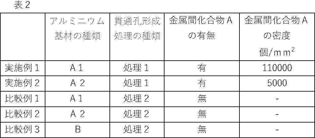
国際公開第2017/018462号の実施例5および実施例11に記載の方法をそれぞれ用いてアルミニウム箔を作製した。
比較例4は小さい金属間化合物が少ないアルミニウム基材を使用した例であり、比較例5は、小さい金属間化合物を含むアルミニウム基材を使用した例である。
比較例4および5と略同じ貫通孔物性(平均開口径および平均開口率)とするために、貫通孔形成工程の処理条件を変更した以外は、実施例1と同様にしてアルミニウム箔を作製した。
上記と同様にして初期抵抗値および4週間強制経時後の抵抗値を測定した。また、上記と同様にしてFE-AESを用い、SEM観察、および表面の酸化膜の最表面から深さ方向に向けて元素分布を行い、金属間化合物Aの密度を求めた。また、酸化膜の膜厚について、初期値および4週間強制経時後の値を求めた。また、酸化膜の密度(初期値)についても求めた。
処理条件等を表3に示し、結果を表4に示す。
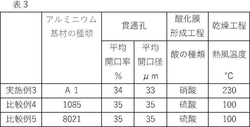
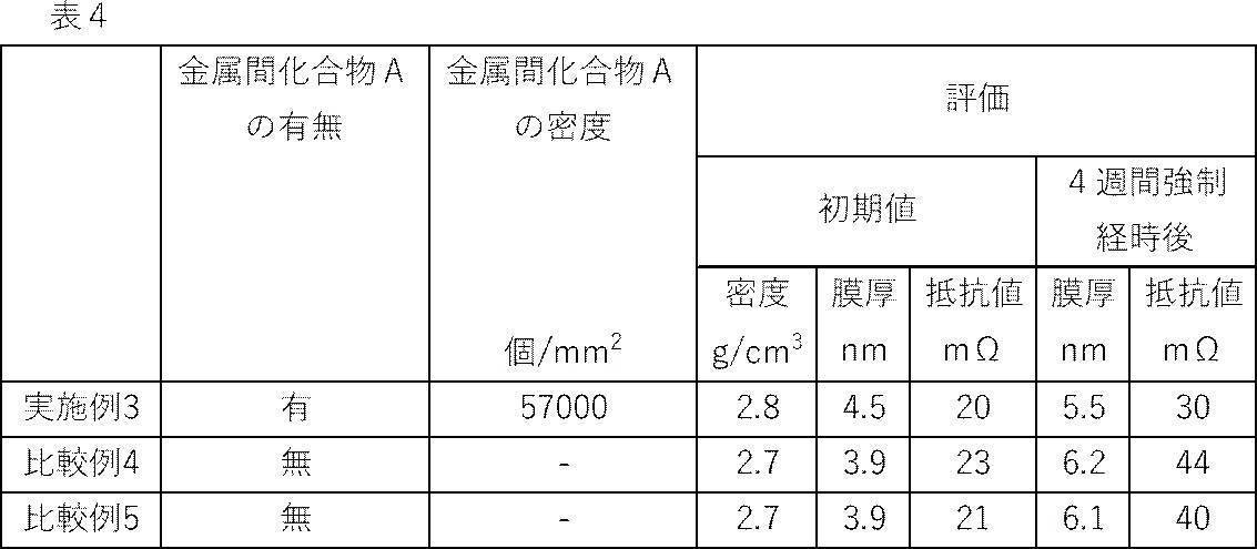
国際公開第2018/062046号の実施例1に記載の方法を用いてアルミニウム箔を作製した。
比較例6は小さい金属間化合物が多いアルミニウム基材を使用した例である。
比較例6と略同じ貫通孔物性(平均開口径および平均開口率)とするために、貫通孔形成工程の処理条件を変更した以外は、実施例1と同様にしてアルミニウム箔を作製した。
上記と同様にして初期抵抗値、3週間強制経時後および8週間強制経時後の抵抗値を測定した。また、上記と同様にしてFE-AESを用い、SEM観察、および表面の酸化膜の最表面から深さ方向に向けて元素分布を行い、金属間化合物Aの密度を求めた。また、酸化膜の膜厚について、初期値、3週間強制経時後および8週間強制経時後の値を求めた。また、酸化膜の密度(初期値)についても求めた。
処理条件等を表5に示し、結果を表6に示す。
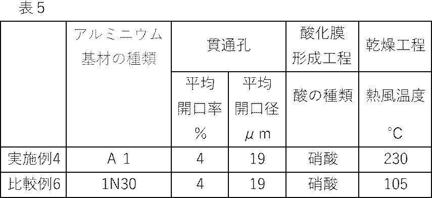
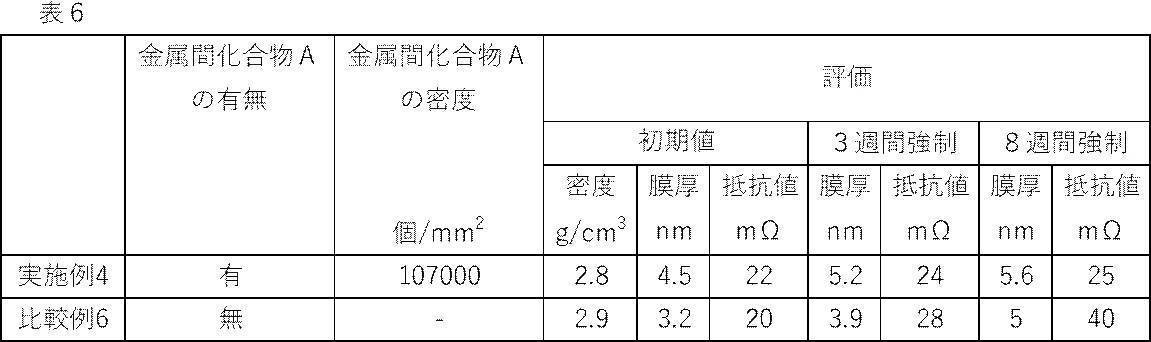
実施例2と同様にしてアルミニウム箔を作製した後、溶剤(MEK(メチルエチルケトン))で洗浄してアルミニウム箔を作製した。
実施例2と同様にしてアルミニウム箔を作製した後、溶剤(MEK(メチルエチルケトン))で洗浄し、その後、未処理のアルミニウム箔(A1085材、未処理、未洗浄)で1週間梱包した。すなわち、実施例5と同様にして作製したアルミニウム箔を未処理のアルミニウム箔で1週間梱包した。
ここで、未処理アルミニウム箔で梱包して保存することは、未処理アルミニウム箔表面に残存する微量の圧延油がアルミニウム箔の表面に転写するため、水接触角が増加する。この点を利用し、実施例6,7,10はそれぞれ接触角が大きい例として作製した。
実施例2と同様にしてアルミニウム箔を作製した後、未処理アルミニウム箔で1週間梱包した。
実施例2と同様にしてアルミニウム箔を作製した後、コロナ処理を1回行い親水化してアルミニウム箔を作製した。コロナ処理は春日電機株式会社製の処理装置を用いた。コロナ処理の出力は600Wとした。
実施例2と同様にしてアルミニウム箔を作製した後、コロナ処理を2回行い親水化してアルミニウム箔を作製した。
実施例2と同様にしてアルミニウム箔を作製した後、未処理アルミニウム箔で2週間梱包した。
測定までの待ち時間 2000ms
作成液量 1.8μL
水接触角の測定結果を表7に示す。
<初期抵抗および強制経時抵抗>
実施例2、5~10のアルミニウム箔について、上記と同様にして初期抵抗、および、強制経時抵抗を測定し、同じ基準で評価した。なお、実施例6,7,10のように、未処理アルミニウムで梱包して保管する実施例については、梱包保管中の経時の影響を最小限にするため、低湿環境で所定の期間保管後、梱包から取り出し、初期抵抗および強制経時抵抗を測定した。
実施例2、5~10のアルミニウム箔について、初期抵抗の測定のため電極材料を塗布する際に、均一に塗布できるか目視で確認した。
結果を表7に示す。
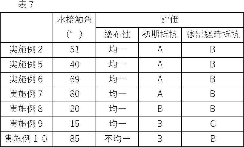
ここで、未処理アルミニウム箔で梱包保管した実施例6および7はそれぞれ、同条件で作製した実施例2,5に対して、水接触角が大きくなっている。これは未処理アルミニウム箔で梱包保管したことで、未処理アルミニウム箔表面に残存する微量の圧延油がアルミニウム箔に転写して、それぞれ元の状態(梱包保管前)よりも水接触角が増加しているものである。また、実施例10は実施例8よりも長期間、梱包保管したものである。実施例10は、梱包保管期間が長いため、水接触角がさらに大きくなって、80°を超えている。その結果、実施例10は他の実施例と比較して塗布性が不均一になった。
なお、実施例10は、塗布性が不均一であるため、電極材料とアルミニウム箔との接触状態が不十分となり、初期抵抗が実施例2に比べて悪化したものと考えられる。一方、実施例10の強制経時抵抗は、表面の水接触角が大きく撥水性に近いため、あまり悪化せず実施例2と同レベルであった。
以上より本発明の効果は明らかである。
2 水酸化アルミニウム皮膜
3 貫通孔を有するアルミニウム基材
4 貫通孔を有する水酸化アルミニウム皮膜
5 貫通孔
10 アルミニウム箔
14 酸化膜
16 金属間化合物
100 抵抗測定器
102 加圧式導電専用端子
104 加圧式絶縁端子
106 カーボン層
Claims (10)
- 厚さ方向に貫通する複数の貫通孔を有するアルミニウム箔であって、
前記アルミニウム箔は、表面に酸化膜を有し、
前記酸化膜はアルミニウムに対する酸素の元素比率O/Alが2以上4以下である金属間化合物を有し、
前記金属間化合物の密度が500個/mm2以上であるアルミニウム箔。 - 前記金属間化合物の円相当直径が1μm以下である請求項1に記載のアルミニウム箔。
- 前記酸化膜が酸化アルミニウムを70質量%以上含む請求項1または2に記載のアルミニウム箔。
- 前記酸化膜の表面の水接触角が20°~80°である請求項1~3のいずれか一項に記載のアルミニウム箔。
- 前記貫通孔の平均開口径が0.1μm~100μmである請求項1~4のいずれか一項に記載のアルミニウム箔。
- 平均開口径が0.1μm~100μmの貫通していない凹部を有し、
前記凹部の占有率が1%以上である請求項1~5のいずれか一項に記載のアルミニウム箔。 - 請求項1~6のいずれか一項に記載のアルミニウム箔を製造するアルミニウム箔の製造方法であって、
アルミニウム基材に貫通孔を形成する貫通孔形成工程と、
前記アルミニウム基材をアルカリ性水溶液に接触させて最表層を溶解するアルカリ処理工程と、
前記アルカリ処理工程後の前記アルミニウム基材を酸性水溶液に接触させて、前記アルミニウム基材の表面に酸化膜を形成する酸処理工程と、を有するアルミニウム箔の製造方法。 - 請求項1~6のいずれか一項に記載のアルミニウム箔を用いた集電体。
- 請求項8に記載の集電体を用いたリチウムイオンキャパシタ。
- 請求項8に記載の集電体を用いたリチウムイオンバッテリー。
Priority Applications (3)
| Application Number | Priority Date | Filing Date | Title |
|---|---|---|---|
| KR1020217031081A KR102534518B1 (ko) | 2019-03-29 | 2020-03-10 | 알루미늄박, 알루미늄박의 제조 방법, 집전체, 리튬 이온 커패시터, 및, 리튬 이온 배터리 |
| JP2021511317A JP7183395B2 (ja) | 2019-03-29 | 2020-03-10 | アルミニウム箔、アルミニウム箔の製造方法、集電体、リチウムイオンキャパシタ、および、リチウムイオンバッテリー |
| CN202080024860.2A CN113646460B (zh) | 2019-03-29 | 2020-03-10 | 铝箔、铝箔的制造方法、集电体、锂离子电容器及锂离子电池 |
Applications Claiming Priority (4)
| Application Number | Priority Date | Filing Date | Title |
|---|---|---|---|
| JP2019067485 | 2019-03-29 | ||
| JP2019-067485 | 2019-03-29 | ||
| JP2019177082 | 2019-09-27 | ||
| JP2019-177082 | 2019-09-27 |
Publications (1)
| Publication Number | Publication Date |
|---|---|
| WO2020203085A1 true WO2020203085A1 (ja) | 2020-10-08 |
Family
ID=72668560
Family Applications (1)
| Application Number | Title | Priority Date | Filing Date |
|---|---|---|---|
| PCT/JP2020/010221 Ceased WO2020203085A1 (ja) | 2019-03-29 | 2020-03-10 | アルミニウム箔、アルミニウム箔の製造方法、集電体、リチウムイオンキャパシタ、および、リチウムイオンバッテリー |
Country Status (4)
| Country | Link |
|---|---|
| JP (1) | JP7183395B2 (ja) |
| KR (1) | KR102534518B1 (ja) |
| CN (1) | CN113646460B (ja) |
| WO (1) | WO2020203085A1 (ja) |
Citations (2)
| Publication number | Priority date | Publication date | Assignee | Title |
|---|---|---|---|---|
| WO2013018164A1 (ja) * | 2011-07-29 | 2013-02-07 | 古河スカイ株式会社 | 電極集電体用アルミニウム合金箔及びその製造方法 |
| WO2018062046A1 (ja) * | 2016-09-29 | 2018-04-05 | 富士フイルム株式会社 | 電極用アルミニウム部材および電極用アルミニウム部材の製造方法 |
Family Cites Families (18)
| Publication number | Priority date | Publication date | Assignee | Title |
|---|---|---|---|---|
| JPH05247571A (ja) * | 1991-11-25 | 1993-09-24 | Nippon Steel Corp | 微細組織構造をもつアルミニウム合金 |
| JP3232841B2 (ja) * | 1993-12-24 | 2001-11-26 | 松下電器産業株式会社 | コンデンサおよびその製造方法 |
| JPH083672A (ja) * | 1994-06-22 | 1996-01-09 | Furukawa Electric Co Ltd:The | 溶接性、耐食性に優れたアルミニウム板 |
| JP2001049492A (ja) * | 1999-08-11 | 2001-02-20 | Nippon Alum Co Ltd | アルマイト処理方法 |
| JP2001059187A (ja) * | 1999-08-20 | 2001-03-06 | Dainippon Printing Co Ltd | 粗面化された金属箔 |
| JP2003191659A (ja) * | 2001-12-25 | 2003-07-09 | Fuji Photo Film Co Ltd | 平版印刷版用アルミニウム支持体とその製造方法、および平版印刷原版 |
| JP2014222669A (ja) * | 2009-02-03 | 2014-11-27 | ソニー株式会社 | セパレータおよび電池 |
| WO2012137497A1 (ja) * | 2011-04-05 | 2012-10-11 | 富士フイルム株式会社 | モリブデン電極付光電変換素子用基板および光電変換素子並びに太陽電池 |
| CN102864476B (zh) * | 2012-09-29 | 2014-12-24 | 南京理工大学 | 一种通孔阳极氧化铝模板的制备方法 |
| CN103617894B (zh) * | 2013-11-28 | 2016-08-17 | 长春吉大科诺科技有限责任公司 | 一种超级电容器集流体铝箔的表面氧化处理方法 |
| JP6199416B2 (ja) * | 2014-01-31 | 2017-09-20 | 富士フイルム株式会社 | アルミニウム板の製造方法、アルミニウム板、蓄電デバイス用集電体、蓄電デバイス、防音・吸音材、電磁波シールドおよび建築用材料 |
| CN104576066A (zh) * | 2014-12-27 | 2015-04-29 | 西安交通大学 | 一种高介电常数复合氧化膜的制备方法 |
| JP2016173934A (ja) * | 2015-03-17 | 2016-09-29 | 住友電気工業株式会社 | アルミニウム多孔体、アルミニウム多孔体の製造方法、電極、電気二重層キャパシタ、リチウムイオンキャパシタ及びリチウムイオン電池 |
| CN104966840A (zh) * | 2015-06-24 | 2015-10-07 | 广州鹏辉能源科技股份有限公司 | 一种高安全性的锂离子电池正极集流体及其制备方法与锂离子电池 |
| JPWO2017018462A1 (ja) | 2015-07-30 | 2018-06-28 | 富士フイルム株式会社 | アルミニウム板 |
| WO2017163913A1 (ja) * | 2016-03-25 | 2017-09-28 | 富士フイルム株式会社 | アルミニウム板の製造方法、及び、アルミニウム板の製造装置 |
| CN105734598B (zh) * | 2016-03-29 | 2018-11-27 | 浙江道明光电科技有限公司 | 锂电池软包装用铝塑膜中铝箔的环保化学表面处理方法 |
| CN116940717A (zh) * | 2021-03-02 | 2023-10-24 | 富士胶片株式会社 | 集电体用铝基材、电容器、二次电池及集电体用铝基材的制造方法 |
-
2020
- 2020-03-10 JP JP2021511317A patent/JP7183395B2/ja active Active
- 2020-03-10 WO PCT/JP2020/010221 patent/WO2020203085A1/ja not_active Ceased
- 2020-03-10 CN CN202080024860.2A patent/CN113646460B/zh active Active
- 2020-03-10 KR KR1020217031081A patent/KR102534518B1/ko active Active
Patent Citations (2)
| Publication number | Priority date | Publication date | Assignee | Title |
|---|---|---|---|---|
| WO2013018164A1 (ja) * | 2011-07-29 | 2013-02-07 | 古河スカイ株式会社 | 電極集電体用アルミニウム合金箔及びその製造方法 |
| WO2018062046A1 (ja) * | 2016-09-29 | 2018-04-05 | 富士フイルム株式会社 | 電極用アルミニウム部材および電極用アルミニウム部材の製造方法 |
Also Published As
| Publication number | Publication date |
|---|---|
| CN113646460A (zh) | 2021-11-12 |
| KR102534518B1 (ko) | 2023-05-26 |
| CN113646460B (zh) | 2023-08-15 |
| JP7183395B2 (ja) | 2022-12-05 |
| KR20210133270A (ko) | 2021-11-05 |
| JPWO2020203085A1 (ja) | 2020-10-08 |
Similar Documents
| Publication | Publication Date | Title |
|---|---|---|
| EP3202957B1 (en) | Aluminum plate | |
| JP6936864B2 (ja) | アルミニウム箔および電極用アルミニウム部材 | |
| TWI596220B (zh) | 銅箔、負極集電體以及非水系二次電池的負極材 | |
| WO2016017380A1 (ja) | アルミニウム板 | |
| CN106795646A (zh) | 铝板和铝板的制造方法 | |
| US20180166690A1 (en) | Aluminum plate and method for manufacturing aluminum plate | |
| US11527760B2 (en) | Aluminum member for electrodes and method of producing aluminum member for electrodes | |
| JP2013138050A (ja) | キャパシタ用電極、キャパシタ、および、キャパシタ用電極の製造方法 | |
| JP7777577B2 (ja) | 集電体用アルミニウム基材、キャパシタ、二次電池、および、集電体用アルミニウム基材の製造方法 | |
| CN117878333A (zh) | 电池用表面处理金属板 | |
| WO2020203085A1 (ja) | アルミニウム箔、アルミニウム箔の製造方法、集電体、リチウムイオンキャパシタ、および、リチウムイオンバッテリー | |
| JP7526800B2 (ja) | 集電体用アルミニウム部材、ならびに、リチウムイオンキャパシタ、電気二重層キャパシタ、半固体電池、固体電池、および、非水電解液を使用する二次電池 | |
| JP2023110037A (ja) | 電池用表面処理金属板 | |
| JP2013165018A (ja) | 非水電解質二次電池ケース用鋼材 | |
| JP2011063887A (ja) | エッチング特性に優れた電解コンデンサ電極用アルミニウム材の製造方法、アルミニウム電解コンデンサ用電極材ならびにアルミニウム電解コンデンサ | |
| JP2023029245A (ja) | 有機物層被覆亜鉛箔及びその製造方法 |
Legal Events
| Date | Code | Title | Description |
|---|---|---|---|
| 121 | Ep: the epo has been informed by wipo that ep was designated in this application |
Ref document number: 20783134 Country of ref document: EP Kind code of ref document: A1 |
|
| ENP | Entry into the national phase |
Ref document number: 2021511317 Country of ref document: JP Kind code of ref document: A |
|
| ENP | Entry into the national phase |
Ref document number: 20217031081 Country of ref document: KR Kind code of ref document: A |
|
| NENP | Non-entry into the national phase |
Ref country code: DE |
|
| 122 | Ep: pct application non-entry in european phase |
Ref document number: 20783134 Country of ref document: EP Kind code of ref document: A1 |