WO2020202851A1 - 排ガス浄化フィルタ - Google Patents
排ガス浄化フィルタ Download PDFInfo
- Publication number
- WO2020202851A1 WO2020202851A1 PCT/JP2020/006216 JP2020006216W WO2020202851A1 WO 2020202851 A1 WO2020202851 A1 WO 2020202851A1 JP 2020006216 W JP2020006216 W JP 2020006216W WO 2020202851 A1 WO2020202851 A1 WO 2020202851A1
- Authority
- WO
- WIPO (PCT)
- Prior art keywords
- exhaust gas
- gas purification
- purification filter
- partition wall
- pore
- Prior art date
- Legal status (The legal status is an assumption and is not a legal conclusion. Google has not performed a legal analysis and makes no representation as to the accuracy of the status listed.)
- Ceased
Links
Images


Classifications
-
- F—MECHANICAL ENGINEERING; LIGHTING; HEATING; WEAPONS; BLASTING
- F01—MACHINES OR ENGINES IN GENERAL; ENGINE PLANTS IN GENERAL; STEAM ENGINES
- F01N—GAS-FLOW SILENCERS OR EXHAUST APPARATUS FOR MACHINES OR ENGINES IN GENERAL; GAS-FLOW SILENCERS OR EXHAUST APPARATUS FOR INTERNAL-COMBUSTION ENGINES
- F01N3/00—Exhaust or silencing apparatus having means for purifying, rendering innocuous, or otherwise treating exhaust
- F01N3/02—Exhaust or silencing apparatus having means for purifying, rendering innocuous, or otherwise treating exhaust for cooling, or for removing solid constituents of, exhaust
- F01N3/021—Exhaust or silencing apparatus having means for purifying, rendering innocuous, or otherwise treating exhaust for cooling, or for removing solid constituents of, exhaust by means of filters
- F01N3/022—Exhaust or silencing apparatus having means for purifying, rendering innocuous, or otherwise treating exhaust for cooling, or for removing solid constituents of, exhaust by means of filters characterised by specially adapted filtering structure, e.g. honeycomb, mesh or fibrous
- F01N3/0222—Exhaust or silencing apparatus having means for purifying, rendering innocuous, or otherwise treating exhaust for cooling, or for removing solid constituents of, exhaust by means of filters characterised by specially adapted filtering structure, e.g. honeycomb, mesh or fibrous the structure being monolithic, e.g. honeycombs
-
- B—PERFORMING OPERATIONS; TRANSPORTING
- B01—PHYSICAL OR CHEMICAL PROCESSES OR APPARATUS IN GENERAL
- B01D—SEPARATION
- B01D39/00—Filtering material for liquid or gaseous fluids
- B01D39/14—Other self-supporting filtering material ; Other filtering material
- B01D39/20—Other self-supporting filtering material ; Other filtering material of inorganic material, e.g. asbestos paper, metallic filtering material of non-woven wires
- B01D39/2068—Other inorganic materials, e.g. ceramics
- B01D39/2072—Other inorganic materials, e.g. ceramics the material being particulate or granular
- B01D39/2075—Other inorganic materials, e.g. ceramics the material being particulate or granular sintered or bonded by inorganic agents
-
- B—PERFORMING OPERATIONS; TRANSPORTING
- B01—PHYSICAL OR CHEMICAL PROCESSES OR APPARATUS IN GENERAL
- B01D—SEPARATION
- B01D46/00—Filters or filtering processes specially modified for separating dispersed particles from gases or vapours
- B01D46/24—Particle separators, e.g. dust precipitators, using rigid hollow filter bodies
- B01D46/2403—Particle separators, e.g. dust precipitators, using rigid hollow filter bodies characterised by the physical shape or structure of the filtering element
- B01D46/2418—Honeycomb filters
- B01D46/2425—Honeycomb filters characterized by parameters related to the physical properties of the honeycomb structure material
- B01D46/2429—Honeycomb filters characterized by parameters related to the physical properties of the honeycomb structure material of the honeycomb walls or cells
-
- B—PERFORMING OPERATIONS; TRANSPORTING
- B01—PHYSICAL OR CHEMICAL PROCESSES OR APPARATUS IN GENERAL
- B01D—SEPARATION
- B01D46/00—Filters or filtering processes specially modified for separating dispersed particles from gases or vapours
- B01D46/24—Particle separators, e.g. dust precipitators, using rigid hollow filter bodies
- B01D46/2403—Particle separators, e.g. dust precipitators, using rigid hollow filter bodies characterised by the physical shape or structure of the filtering element
- B01D46/2418—Honeycomb filters
- B01D46/2425—Honeycomb filters characterized by parameters related to the physical properties of the honeycomb structure material
- B01D46/24491—Porosity
-
- B—PERFORMING OPERATIONS; TRANSPORTING
- B01—PHYSICAL OR CHEMICAL PROCESSES OR APPARATUS IN GENERAL
- B01D—SEPARATION
- B01D46/00—Filters or filtering processes specially modified for separating dispersed particles from gases or vapours
- B01D46/24—Particle separators, e.g. dust precipitators, using rigid hollow filter bodies
- B01D46/2403—Particle separators, e.g. dust precipitators, using rigid hollow filter bodies characterised by the physical shape or structure of the filtering element
- B01D46/2418—Honeycomb filters
- B01D46/2425—Honeycomb filters characterized by parameters related to the physical properties of the honeycomb structure material
- B01D46/24492—Pore diameter
-
- B—PERFORMING OPERATIONS; TRANSPORTING
- B01—PHYSICAL OR CHEMICAL PROCESSES OR APPARATUS IN GENERAL
- B01D—SEPARATION
- B01D46/00—Filters or filtering processes specially modified for separating dispersed particles from gases or vapours
- B01D46/24—Particle separators, e.g. dust precipitators, using rigid hollow filter bodies
- B01D46/2403—Particle separators, e.g. dust precipitators, using rigid hollow filter bodies characterised by the physical shape or structure of the filtering element
- B01D46/2418—Honeycomb filters
- B01D46/2498—The honeycomb filter being defined by mathematical relationships
-
- B—PERFORMING OPERATIONS; TRANSPORTING
- B01—PHYSICAL OR CHEMICAL PROCESSES OR APPARATUS IN GENERAL
- B01D—SEPARATION
- B01D53/00—Separation of gases or vapours; Recovering vapours of volatile solvents from gases; Chemical or biological purification of waste gases, e.g. engine exhaust gases, smoke, fumes, flue gases, aerosols
- B01D53/34—Chemical or biological purification of waste gases
- B01D53/92—Chemical or biological purification of waste gases of engine exhaust gases
- B01D53/94—Chemical or biological purification of waste gases of engine exhaust gases by catalytic processes
- B01D53/944—Simultaneously removing carbon monoxide, hydrocarbons or carbon making use of oxidation catalysts
-
- B—PERFORMING OPERATIONS; TRANSPORTING
- B01—PHYSICAL OR CHEMICAL PROCESSES OR APPARATUS IN GENERAL
- B01J—CHEMICAL OR PHYSICAL PROCESSES, e.g. CATALYSIS OR COLLOID CHEMISTRY; THEIR RELEVANT APPARATUS
- B01J35/00—Catalysts, in general, characterised by their form or physical properties
- B01J35/50—Catalysts, in general, characterised by their form or physical properties characterised by their shape or configuration
- B01J35/56—Foraminous structures having flow-through passages or channels, e.g. grids or three-dimensional monoliths
- B01J35/57—Honeycombs
-
- B—PERFORMING OPERATIONS; TRANSPORTING
- B01—PHYSICAL OR CHEMICAL PROCESSES OR APPARATUS IN GENERAL
- B01J—CHEMICAL OR PHYSICAL PROCESSES, e.g. CATALYSIS OR COLLOID CHEMISTRY; THEIR RELEVANT APPARATUS
- B01J35/00—Catalysts, in general, characterised by their form or physical properties
- B01J35/60—Catalysts, in general, characterised by their form or physical properties characterised by their surface properties or porosity
- B01J35/64—Pore diameter
- B01J35/657—Pore diameter larger than 1000 nm
-
- B—PERFORMING OPERATIONS; TRANSPORTING
- B01—PHYSICAL OR CHEMICAL PROCESSES OR APPARATUS IN GENERAL
- B01J—CHEMICAL OR PHYSICAL PROCESSES, e.g. CATALYSIS OR COLLOID CHEMISTRY; THEIR RELEVANT APPARATUS
- B01J37/00—Processes, in general, for preparing catalysts; Processes, in general, for activation of catalysts
- B01J37/02—Impregnation, coating or precipitation
- B01J37/0215—Coating
-
- F—MECHANICAL ENGINEERING; LIGHTING; HEATING; WEAPONS; BLASTING
- F01—MACHINES OR ENGINES IN GENERAL; ENGINE PLANTS IN GENERAL; STEAM ENGINES
- F01N—GAS-FLOW SILENCERS OR EXHAUST APPARATUS FOR MACHINES OR ENGINES IN GENERAL; GAS-FLOW SILENCERS OR EXHAUST APPARATUS FOR INTERNAL-COMBUSTION ENGINES
- F01N3/00—Exhaust or silencing apparatus having means for purifying, rendering innocuous, or otherwise treating exhaust
- F01N3/02—Exhaust or silencing apparatus having means for purifying, rendering innocuous, or otherwise treating exhaust for cooling, or for removing solid constituents of, exhaust
- F01N3/021—Exhaust or silencing apparatus having means for purifying, rendering innocuous, or otherwise treating exhaust for cooling, or for removing solid constituents of, exhaust by means of filters
- F01N3/022—Exhaust or silencing apparatus having means for purifying, rendering innocuous, or otherwise treating exhaust for cooling, or for removing solid constituents of, exhaust by means of filters characterised by specially adapted filtering structure, e.g. honeycomb, mesh or fibrous
-
- F—MECHANICAL ENGINEERING; LIGHTING; HEATING; WEAPONS; BLASTING
- F01—MACHINES OR ENGINES IN GENERAL; ENGINE PLANTS IN GENERAL; STEAM ENGINES
- F01N—GAS-FLOW SILENCERS OR EXHAUST APPARATUS FOR MACHINES OR ENGINES IN GENERAL; GAS-FLOW SILENCERS OR EXHAUST APPARATUS FOR INTERNAL-COMBUSTION ENGINES
- F01N3/00—Exhaust or silencing apparatus having means for purifying, rendering innocuous, or otherwise treating exhaust
- F01N3/08—Exhaust or silencing apparatus having means for purifying, rendering innocuous, or otherwise treating exhaust for rendering innocuous
- F01N3/10—Exhaust or silencing apparatus having means for purifying, rendering innocuous, or otherwise treating exhaust for rendering innocuous by thermal or catalytic conversion of noxious components of exhaust
- F01N3/24—Exhaust or silencing apparatus having means for purifying, rendering innocuous, or otherwise treating exhaust for rendering innocuous by thermal or catalytic conversion of noxious components of exhaust characterised by constructional aspects of converting apparatus
- F01N3/28—Construction of catalytic reactors
-
- B—PERFORMING OPERATIONS; TRANSPORTING
- B01—PHYSICAL OR CHEMICAL PROCESSES OR APPARATUS IN GENERAL
- B01D—SEPARATION
- B01D2239/00—Aspects relating to filtering material for liquid or gaseous fluids
- B01D2239/04—Additives and treatments of the filtering material
- B01D2239/0471—Surface coating material
- B01D2239/0478—Surface coating material on a layer of the filter
-
- B—PERFORMING OPERATIONS; TRANSPORTING
- B01—PHYSICAL OR CHEMICAL PROCESSES OR APPARATUS IN GENERAL
- B01D—SEPARATION
- B01D2239/00—Aspects relating to filtering material for liquid or gaseous fluids
- B01D2239/12—Special parameters characterising the filtering material
- B01D2239/1216—Pore size
-
- B—PERFORMING OPERATIONS; TRANSPORTING
- B01—PHYSICAL OR CHEMICAL PROCESSES OR APPARATUS IN GENERAL
- B01D—SEPARATION
- B01D2255/00—Catalysts
- B01D2255/10—Noble metals or compounds thereof
- B01D2255/102—Platinum group metals
- B01D2255/1021—Platinum
-
- B—PERFORMING OPERATIONS; TRANSPORTING
- B01—PHYSICAL OR CHEMICAL PROCESSES OR APPARATUS IN GENERAL
- B01D—SEPARATION
- B01D2255/00—Catalysts
- B01D2255/10—Noble metals or compounds thereof
- B01D2255/102—Platinum group metals
- B01D2255/1023—Palladium
-
- B—PERFORMING OPERATIONS; TRANSPORTING
- B01—PHYSICAL OR CHEMICAL PROCESSES OR APPARATUS IN GENERAL
- B01D—SEPARATION
- B01D2255/00—Catalysts
- B01D2255/10—Noble metals or compounds thereof
- B01D2255/102—Platinum group metals
- B01D2255/1025—Rhodium
-
- B—PERFORMING OPERATIONS; TRANSPORTING
- B01—PHYSICAL OR CHEMICAL PROCESSES OR APPARATUS IN GENERAL
- B01D—SEPARATION
- B01D2255/00—Catalysts
- B01D2255/20—Metals or compounds thereof
- B01D2255/206—Rare earth metals
- B01D2255/2065—Cerium
-
- B—PERFORMING OPERATIONS; TRANSPORTING
- B01—PHYSICAL OR CHEMICAL PROCESSES OR APPARATUS IN GENERAL
- B01D—SEPARATION
- B01D2255/00—Catalysts
- B01D2255/20—Metals or compounds thereof
- B01D2255/207—Transition metals
- B01D2255/20715—Zirconium
-
- B—PERFORMING OPERATIONS; TRANSPORTING
- B01—PHYSICAL OR CHEMICAL PROCESSES OR APPARATUS IN GENERAL
- B01D—SEPARATION
- B01D2255/00—Catalysts
- B01D2255/40—Mixed oxides
- B01D2255/407—Zr-Ce mixed oxides
-
- B—PERFORMING OPERATIONS; TRANSPORTING
- B01—PHYSICAL OR CHEMICAL PROCESSES OR APPARATUS IN GENERAL
- B01D—SEPARATION
- B01D2255/00—Catalysts
- B01D2255/90—Physical characteristics of catalysts
- B01D2255/92—Dimensions
- B01D2255/9205—Porosity
-
- Y—GENERAL TAGGING OF NEW TECHNOLOGICAL DEVELOPMENTS; GENERAL TAGGING OF CROSS-SECTIONAL TECHNOLOGIES SPANNING OVER SEVERAL SECTIONS OF THE IPC; TECHNICAL SUBJECTS COVERED BY FORMER USPC CROSS-REFERENCE ART COLLECTIONS [XRACs] AND DIGESTS
- Y02—TECHNOLOGIES OR APPLICATIONS FOR MITIGATION OR ADAPTATION AGAINST CLIMATE CHANGE
- Y02T—CLIMATE CHANGE MITIGATION TECHNOLOGIES RELATED TO TRANSPORTATION
- Y02T10/00—Road transport of goods or passengers
- Y02T10/10—Internal combustion engine [ICE] based vehicles
- Y02T10/12—Improving ICE efficiencies
Definitions
- the present disclosure relates to an exhaust gas purification filter capable of collecting particulate matter discharged from an internal combustion engine.
- Exhaust gas emitted from internal combustion engines such as diesel engines and gasoline engines, and heat engines such as boilers contains particulate matter called particulate matter. Particulate is hereinafter appropriately referred to as "PM".
- An exhaust gas purification filter is used to collect PM in the exhaust gas.
- the exhaust gas purification filter generally has a honeycomb structure portion having a plurality of cells formed by being partitioned by a porous partition wall, and a sealing portion that alternately closes adjacent cells.
- PM contained in the exhaust gas is collected in the pores of the partition wall, and it is required to reduce the pressure loss while increasing the collection rate of PM.
- the PM collection rate is hereinafter appropriately referred to as “collection rate”
- the pressure loss is hereinafter appropriately referred to as "pressure loss”.
- pressure loss In order to reduce the pressure loss, it is effective to increase the porosity of the partition wall, but if the porosity is increased, the collection rate tends to decrease.
- Patent Document 1 discloses a technique in which the pore volume having a pore diameter of 10 to 50 ⁇ m is set to 75% or more and the pore volume having a pore diameter of 10 ⁇ m or less and a pore diameter of 50 ⁇ m or more is reduced in the pore diameter distribution of the filter. According to Patent Document 1, by adopting the above configuration, PM whose diameter has been reduced by improving the diesel engine can be collected with high efficiency.
- the average pore diameter (A) ⁇ m measured by the mercury intrusion method and the average pore diameter (B) ⁇ m measured by the bubble point method are ⁇ (AB) / B ⁇ ⁇ 100.
- Disclosed is a technique in which the average pore diameter difference ratio represented is 35 (%) or less, the average pore diameter (B) is 15 to 30 ⁇ m, and the maximum pore diameter measured by the bubble point method is 150 ⁇ m or less.
- PM whose diameter has been reduced by improving the diesel engine can be collected with high efficiency.
- Micro PM with a small particle size tends to cause Brownian motion, and in exhaust gas containing a large amount of micro PM, the proportion of PM that undergoes Brownian motion is high. As a result, the collection of PM into the pores is dominated by the collision of PM with the pore wall due to Brownian motion rather than the inertial collision of PM with the pore wall due to gas flow. Therefore, it is considered that PM can be collected with high efficiency by adjusting the pore size distribution disclosed in Patent Document 1.
- the exhaust gas contains a large amount of SOF (Solble Organic Fraction), so the particle size of PM in the exhaust gas becomes large.
- SOF Solble Organic Fraction
- the particle size of PM in the exhaust gas becomes large.
- Coarse PM having a large particle size is less likely to cause Brownian motion, and inertial collision with the pore wall due to gas flow is dominant in the collection of coarse PM.
- the low exhaust temperature at the time of starting the engine also reduces the PM that makes Brownian motion, which is a factor that the collection due to the inertial collision becomes dominant.
- the present disclosure is intended to provide an exhaust gas purification filter having a high collection rate and low pressure loss.
- One aspect of the present disclosure is a honeycomb structure having a porous partition wall and a plurality of cells partitioned by the partition wall to form an exhaust gas flow path.
- an exhaust gas purification filter provided with a sealing portion that alternately closes the inflow side end face or the outflow side end face of the gas in the cell.
- the exhaust gas purification filter contains 5% or more of the total pore volume of fine pores having a pore diameter of 10 ⁇ m or less in the honeycomb structure measured by a mercury injection method.
- the partition wall has a plurality of communication holes for communicating between the cells adjacent to the partition wall, and the maximum diameter ⁇ 1 ⁇ m and the minimum diameter ⁇ 2 ⁇ m in the communication holes are ⁇ 1 ⁇ 50, 100 ⁇ ⁇ 2. It is in an exhaust gas purification filter having a constricted communication hole with / ⁇ 1 ⁇ 20.
- the fine pores having a pore diameter of 10 ⁇ m or less are 5% or more of the total pore volume. That is, there are many micropores that can collect coarse PM due to inertial collision. As a result, the exhaust gas purification filter has a high probability of collecting the coarse PM due to the inertial collision, and can sufficiently collect the coarse PM in the micropores.
- the exhaust gas purification filter has a constricted communication hole.
- the constricted type communication hole is a communication hole in which the maximum diameter ⁇ 1 ⁇ m and the minimum diameter ⁇ 2 ⁇ m are ⁇ 1 ⁇ 50 and 100 ⁇ ⁇ 2 / ⁇ 1 ⁇ 20. Exhaust gas inflow tends to concentrate in the communication hole where the maximum diameter ⁇ 1 is 50 ⁇ m or more, and the probability of inertial collision is usually low, but in the constricted communication hole, 100 ⁇ ⁇ 2 / ⁇ 1 ⁇ 20. Since it has a portion having the smallest diameter (hereinafter, appropriately referred to as a "necked portion"), the probability of inertial collision is high.
- the collection efficiency of coarse PM is increased. Furthermore, the constriction type communication holes, since the exhaust gas flow path is throttled by the constricted portion of the minimum diameter [Phi 2 [mu] m, while having a larger diameter with a maximum diameter [Phi 1 50 [mu] m or more, concentrated to constriction type communication hole The inflow of exhaust gas is suppressed, and the gas flow is dispersed in other pores such as micropores having higher collection efficiency for PM. As a result, the PM collection efficiency becomes high and the PM collection rate becomes high.
- the PM collection efficiency is improved by using the large pores, so that the increase in the pressure loss is suppressed. That is, the PM collection rate becomes sufficiently high while suppressing the increase in pressure loss.
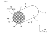
- FIG. 1 is a perspective view of the exhaust gas purification filter according to the first embodiment.
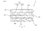
- FIG. 2 is an enlarged partial cross-sectional view of the exhaust gas purification filter in the axial direction according to the first embodiment.
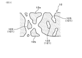
- FIG. 3 is an enlarged sectional schematic view of a partition wall of the exhaust gas purification filter according to the first embodiment.
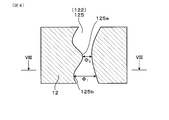
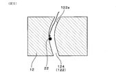
- FIG. 4 is an enlarged sectional schematic view of a partition wall showing an example of a simplified constricted communication hole in the first embodiment.
- FIG. 5 is an enlarged cross-sectional schematic view of a partition wall showing the behavior of coarse PM in the simplified micropores in the first embodiment.
- FIG. 1 is a perspective view of the exhaust gas purification filter according to the first embodiment.
- FIG. 2 is an enlarged partial cross-sectional view of the exhaust gas purification filter in the axial direction according to the first embodiment.
- FIG. 3 is an enlarged sectional schematic view of a partition wall of the exhaust gas purification filter according to the first embodiment.
- FIG. 4 is an enlarged section
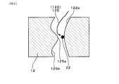
- FIG. 6 is an enlarged cross-sectional schematic view of the partition wall showing an example of the behavior of the coarse PM in the simplified constricted communication hole in the first embodiment.
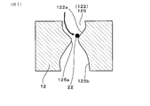
- FIG. 7 is an enlarged cross-sectional schematic view of the partition wall showing another example of the behavior of the coarse PM in the simplified constricted communication hole in the first embodiment.
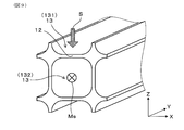
- FIG. 8 is a cross-sectional view taken along the line VIII-VIII of FIG.
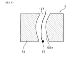
- FIG. 9 is an explanatory diagram regarding the CT scan of the partition wall in the first embodiment.
- FIG. 10A is a diagram showing a measurement sample collection position in the radial direction of the exhaust gas purification filter in the first embodiment
- FIG. 10B is an axial direction and the axial direction of the exhaust gas purification filter in the first embodiment.
- FIG. 11 is a diagram showing a threshold value of binarization processing in 3D modeling in the first embodiment.
- FIG. 12 (a) is a diagram showing an example of arrangement of the pore-forming material when micropores are formed in the first embodiment
- FIG. 12 (b) is a diagram showing an example of arrangement of the pore-forming material when the micropores are formed in the first embodiment. It is an enlarged sectional schematic view of the partition wall.
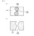
- FIG. 13 (a) is a diagram showing an example of arrangement of the pore-forming material when the constricted communication hole is formed in the first embodiment, and FIG.
- FIG. 13 (b) is a diagram showing an example of the arrangement of the pore-forming material in the case where the constricted communication hole is formed. It is an enlarged cross-sectional schematic diagram of the partition wall in which a hole was formed.
- FIG. 14 is an enlarged sectional schematic view of a partition wall on which a catalyst is supported according to the first embodiment.
- FIG. 15 is a schematic view of the exhaust gas purification system according to the second embodiment.
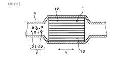
- FIG. 16 is a schematic cross-sectional view of the exhaust gas purification filter arranged in the exhaust pipe according to the second embodiment.
- FIG. 17 is an enlarged cross-sectional schematic view of a partition wall showing the behavior of minute PM in a large pore having a large pore diameter in Comparative Form 1.
- FIG. 18 is an enlarged cross-sectional schematic view of a partition wall showing the behavior of coarse PM in a large pore having a large pore diameter in Comparative Form 1.
- FIG. 19 is an enlarged cross-sectional schematic view of a partition wall showing the behavior of coarse PM in the micropores in Comparative Form 1.
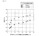
- FIG. 20 is a diagram showing the relationship between the pore volume ratio of the micropores and the collection rate in Experimental Example 1.
- FIG. 21 is a diagram showing the relationship between the pore volume ratio of the micropores and the pressure loss in the first embodiment.
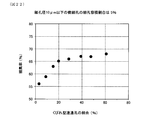
- FIG. 22 is a diagram showing the relationship between the ratio of the constricted communication holes and the collection rate in the first embodiment.
- the exhaust gas purification filter 1 has a honeycomb structure portion 10 and a sealing portion 16.
- the honeycomb structure portion 10 is formed of ceramics such as cordierite, and has, for example, an outer skin 11, a partition wall 12, and a cell 13.
- the exodermis 11 is formed in a cylindrical shape such as a cylindrical shape.
- the axial direction Y of the tubular outer skin 11 will be described below as the axial direction Y of the exhaust gas purification filter 1.
- the arrow in FIG. 2 indicates the flow of exhaust gas when the exhaust gas purification filter 1 is arranged in the path of exhaust gas such as an exhaust pipe.
- the partition wall 12 divides the inside of the exodermis 11 into a large number of cells.
- the partition wall 12 is also generally referred to as a cell wall.
- the partition walls 12 are provided, for example, in a grid pattern.
- the exhaust gas purification filter 1 is a porous body, and as illustrated in FIG. 3, a large number of pores 121 are formed in the partition wall 12. Therefore, the exhaust gas purification filter 1 can collect PM2 contained in the exhaust gas by accumulating it on the surface of the partition wall 12 or in the pores 121.
- the pores 121 are sometimes called pores.
- PM2 is a fine particle called a particulate matter, a particulate matter, a particulate, or the like.
- the average pore diameter of the partition wall 12 is preferably adjusted to, for example, in the range of 15 ⁇ m or more and 22 ⁇ m or less. From the viewpoint of further enhancing this effect, the average pore diameter is more preferably 16 ⁇ m or more and 20 ⁇ m or less, and further preferably 16 ⁇ m or more and 18 ⁇ m or less.
- the porosity of the partition wall 12 is, for example, in the range of 60% or more and 70% or less from the viewpoint of achieving both pressure loss and filter strength at a higher level. It is preferable to adjust to. From the viewpoint of further enhancing such an effect, the porosity is more preferably 62% or more and 68% or less, and further preferably 64% or more and 67% or less.
- the average pore diameter and porosity of the partition wall 12 are measured by the mercury intrusion method, and the detailed measurement method is shown in an experimental example.
- the porous partition wall 12 has a pore size distribution and contains 5% or more of the total pore volume of micropores 124 having a pore size of 10 ⁇ m or less.
- the exhaust gas purification filter 1 can collect PM2 at a high collection rate.
- the pore size distribution and pore size are measured by the mercury intrusion method.
- the ratio of the volume of the micropores 124 to the total pore volume is appropriately referred to as "pore volume ratio of the micropores".
- the exhaust gas purification filter 1 has a large number of cells 13.
- the cell 13 is surrounded by the partition wall 12 and forms an exhaust gas flow path.
- the extension direction of the cell 13 usually coincides with the axial direction Y.
- the cell shape in the filter cross section in the direction orthogonal to the axial direction Y is, for example, a quadrangular shape, but the cell shape is not limited to this.
- the cell shape may be a polygon such as a triangle, a quadrangle, a hexagon, or a circle. Further, the cell shape may be a combination of two or more different shapes.
- the exhaust gas purification filter 1 is, for example, a columnar body such as a columnar body, and its dimensions can be changed as appropriate.
- the exhaust gas purification filter 1 has inflow side end faces 14 and outflow side end faces 15 at both ends in the axial direction Y.
- the inflow side end face 14 is the end face on the side where the exhaust gas flows in
- the outflow side end face 15 is the end face on the side where the exhaust gas flows out.
- the inflow side end face 14 and the outflow side end face 15 mean surfaces relative to each other. That is, when one of the end faces is the inflow side end face 14, the other is the outflow side end face 15.
- the inflow side end face 14 can be referred to as the first end face in the axial direction
- the outflow side end face 15 can be referred to as the second end face in the axial direction.
- the cell 13 can have a first cell 131 and a second cell 132. As illustrated in FIG. 2, the first cell 131 opens in the inflow side end face 14 and is closed by the sealing portion 16 in the outflow side end face 15. The second cell 132 opens to the outflow side end face 15, and is closed by the sealing portion 16 in the inflow side end face 14.
- the sealing portion 16 alternately closes the inflow side end face 14 or the outflow side end face 15 of the cell.
- the sealing portion 16 can be formed of, for example, ceramics such as cordierite, but may be made of other materials.
- the plug-shaped sealing portion 16 is formed, but the shape of the sealing portion 16 is not particularly limited as long as the inflow side end face 14 or the outflow side end face 15 can be sealed.
- the configuration is not shown, it is also possible to form the sealing portion 16 by deforming a part of the partition wall 12 on the inflow side end face 14 or the outflow side end face 15, for example. In this case, since the sealing portion 16 is formed by a part of the partition wall 12, the partition wall 12 and the sealing portion 16 are integrally and continuously formed.
- the first cell 131 and the second cell 132 are arranged alternately so as to be adjacent to each other, for example, in the horizontal direction orthogonal to the axial direction Y and in the vertical direction orthogonal to both the axial direction Y and the horizontal direction. It is formed. That is, when the inflow side end face 14 or the outflow side end face 15 of the exhaust gas purification filter 1 is viewed from the axial direction Y, the first cell 131 and the second cell 132 are arranged in a check pattern, for example.
- the partition wall 12 separates the first cell 131 and the second cell 132 that are adjacent to each other.
- a large number of pores 121 are formed in the partition wall 12.
- the pores 121 in the partition wall 12 include communication holes 122 that communicate between the first cell 131 and the second cell 132 that are adjacent to each other.
- the communication holes 122 are simplified in two dimensions, but it is considered that most of the communication holes 122 intersect in three dimensions.
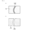
- the partition wall 12 has a constricted communication hole 125.
- FIG. 4 is an enlarged cross-sectional view of the partition wall 12 schematically showing the constricted communication hole 125 in a simplified manner.
- FIG. 4 shows an example of the pores of the partition wall 12 (specifically, the constricted communication hole 125), but the actual partition wall 12 has a large number of pores having various shapes. The same applies to FIGS. 6 to 7.
- the constricted communication hole 125 has a maximum diameter of ⁇ 1 ⁇ m and a minimum diameter of ⁇ 2 ⁇ m, which satisfy the relationship of ⁇ 1 ⁇ 50 and 100 ⁇ ⁇ 2 / ⁇ 1 ⁇ 20. It is 122.
- Maximum diameter [Phi 1 is less than 50 ⁇ m communicating hole 122, communication holes 122 which relationship ⁇ 2 / ⁇ 1 the largest diameter [Phi 1 and the minimum diameter [Phi 2 exceeds 20 does not correspond to the constriction-type communication hole 125.
- the partition wall 12 may have a communication hole 122 other than the constricted communication hole 125 and a non-communication hole 123 that does not communicate with the partition wall 12.
- the collection rate of PM2 can be significantly increased while suppressing an increase in pressure loss even if the fine holes 124 are increased to 5% or more. it can. That is, the exhaust gas purification filter 1 can achieve both a high collection rate and a low voltage loss at a high level. In particular, the pressure loss can be kept low while showing a high collection rate with respect to the coarse PM22. This is considered to be due to the following reasons.
- Coarse PM22 is less likely to cause Brownian motion, and inertial collision in the pores is dominant for collection in the pores.
- the coarse PM22 has an inertial collision with the pore wall in a large pore having a pore diameter of more than 50 ⁇ m, for example, as illustrated in FIG. 18 referred to in the comparative form described later. The probability is low. Therefore, the coarse PM22 having a large particle size easily slips through the large pores and is difficult to be collected.
- the coarse PM22 in the micropores 124 having a pore diameter of 10 ⁇ m or less, the coarse PM22 easily collides with the pore wall due to the flow of exhaust gas. That is, the probability of inertial collision is high. Therefore, the coarse PM22 having a large particle size is likely to be collected in the fine pores 124.
- the partition wall 12 containing 5% or more of the total pore volume of the fine pores 124 having a pore diameter of 10 ⁇ m or less by the mercury intrusion method the number of pores in which inertial collision of the coarse PM 22 is likely to occur increases, so that the collection efficiency of the coarse PM 22 is improved. It becomes higher and the collection rate of PM2 becomes higher.
- the constricted communication hole 125 has, for example, a large diameter portion 125b of 50 ⁇ m or more, but the diameter in the communicating hole 122 is significantly reduced. It has 125a. Due to the presence of the constricted portion 125a, the coarse PM 22 easily collides with the pore wall in the constricted communication hole 125. That is, the probability of inertial collision increases. As a result, in the constricted communication hole 125, the collection efficiency of the coarse PM is high, and the coarse PM 22 is easily collected.
- the flow of exhaust gas is throttled at the constricted portion 125a where 100 ⁇ ⁇ 2 / ⁇ 1 ⁇ 20. Therefore, the exhaust gas is concentrated in the constricted communication hole 125 and becomes difficult to flow, and is dispersed in the pores 121 existing around the constricted communication hole 125. As a result, although the constricted portion 125a does not exist, the exhaust gas tends to flow into other pores such as the fine pores 124, which originally have high collection efficiency for PM2 such as coarse PM22.
- the constricted communication hole 125 can be examined by image analysis of the X-ray CT image of the partition wall 12. As illustrated in FIGS. 4 and 8, the maximum diameter ⁇ 1 and the minimum diameter ⁇ 2 of the diameter of the communication hole 122 such as the constricted communication hole 125 are the maximum values of the diameter in the direction orthogonal to the thickness direction of the partition wall 12. This is the minimum value.
- the diameter of the communication hole 122 means a diameter equivalent to a circle, and is the diameter of a circle having the same area as the area A of the communication hole 122 in the cross section in the direction orthogonal to the thickness direction of the partition wall 12.
- the maximum diameter ⁇ 1 and the minimum diameter ⁇ 2 are measured as follows.
- an X-ray CT image of the partition wall 12 is obtained by an X-ray CT scan.
- the scan direction S in the CT scan is, for example, the direction along the thickness direction of the partition wall 12, and the partition wall on the first cell 131 side that opens to the inflow side end surface 14 that is the upstream end surface.
- partition wall surface 12a From the surface of 12 (hereinafter, appropriately referred to as partition wall surface 12a) toward the surface of the partition wall 12 on the second cell 132 side (hereinafter, appropriately referred to as partition wall back surface 12b) that opens to the outflow side end surface 15 that is the downstream end surface. It is said to be the direction.
- partition wall surface 12a the surface of the partition wall 12 on the second cell 132 side
- the direction along the axial direction Y is the Y direction, perpendicular to the Y direction, and the direction along one of the four partition walls 12 surrounding the second cell 132 is the X direction, and the X direction and the Y direction.
- the direction perpendicular to is the Z direction.
- the symbol Ms in FIG. 9 means the sealing portion 16 on the inflow side end surface 14.
- the scanning direction S may be the direction from the back surface 12b of the partition wall toward the surface surface 12a of the partition wall.
- the X-ray CT apparatus "Versa XRM-500" manufactured by Xradia is used.
- the measurement conditions are a voltage: 80 kV, a step: 0.1 °, and a resolution: 0.6874787 ⁇ m.
- the CT scan is performed as follows. First, a measurement sample is taken from the partition wall 12 of the exhaust gas purification filter 1. Specifically, as shown in FIGS. 10A and 10B, the sealing of the central portion 1a and the inflow side end surface 14 side in the axial direction Y passing through the central portion of the diameter of the exhaust gas purification filter 1. Immediately inner portion 1b of the portion 16, immediately inner portion 1c of the sealing portion 16 on the outflow side end surface 15 side, axial direction Y passing through the central portion of the radius in the exhaust gas purification filter 1, central portion 1d, on the inflow side end surface 14 side. Collected from 6 locations, the inner portion 1e of the sealing portion 16 and the immediately inner portion 1f of the sealing portion 16 on the outflow side end face 15. Regarding the size of the measurement sample, the length in the axial direction Y is 500 ⁇ m, the thickness in the wall thickness direction is the wall thickness, and the length in the direction orthogonal to the axial direction Y and the wall thickness direction is 500 ⁇ m.
- a 3D model of the pores in the partition wall 12 is created by the analysis software: "Geo Dictionary" manufactured by Math2Market.
- the 3D model is an image image created by analysis software. Specifically, a continuous tomographic image in TIF format obtained by X-ray CT is captured as a minimum unit of 0.6874787 ⁇ m / voxel by the importGeo-Vol function of the analysis software.
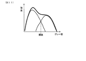
- the graph of the gray value is 3D modeled with the intersection when the graph is separated into two peaks as a threshold value.
- the real part is a ceramic part, that is, a skeleton part, and the pore part is a part where ceramics do not exist.
- the pore part is a part where ceramics do not exist.
- the maximum diameter ⁇ 1 ⁇ m and the minimum diameter ⁇ 2 ⁇ m of each communication hole 122 of the 3D model are measured by the analysis software “Geo Dict”. Specifically, the number of communication holes and the minimum diameter of each communication hole 122 are obtained by the function of "Perulation Path" of "Product” in the analysis software. Next, the partition wall 12 of the 3D model is sliced with a cross section perpendicular to the thickness direction thereof, and the equivalent circle diameter of each communication hole 122 on the slice surface is obtained. Then, the maximum value and the minimum value of the circle-equivalent diameter of each communication hole 122 are obtained.
- the maximum value of each communication hole 122 is the maximum diameter ⁇ 1 of the communication hole 122, and the minimum value of each communication hole 122 is the minimum diameter ⁇ 2 of the communication hole 122.
- the maximum diameter ⁇ 1 and the minimum diameter ⁇ 2 of each communication hole 122 are obtained by slicing the partition wall 12 for each voxel in the thickness direction.
- the communication hole 122 in which ⁇ 1 ⁇ 50 and 100 ⁇ ⁇ 2 / ⁇ 1 ⁇ 20 is a constricted communication hole 125.
- the maximum diameter ⁇ 1 and the minimum diameter ⁇ 2 are arithmetic mean values of the measurement samples collected from the above six locations. The same applies to the proportion of the constricted communication holes.
- the proportion of the constricted communication hole 125 in all the communication holes 122 is preferably 20% or more. In this case, the effect of increasing the collection rate becomes more remarkable.
- the ratio of the constricted communication hole 125 out of all the communication holes 122 is appropriately referred to as "the ratio of the constricted communication hole".
- the ratio of the constricted communication holes 125 is preferably 80% or less.
- the ratio of the constricted communication holes 125 is measured as follows. First, the analysis software "Geo Dictionary" is used to determine the number of all communication holes and the equivalent circle diameter of each communication hole 122.
- the exhaust gas purification filter 1 of this embodiment can be applied to purify the exhaust gas emitted from a normal gasoline engine, but can be applied to purify the exhaust gas emitted from the engine of a hybrid vehicle in which the gasoline engine is frequently stopped and started. It is suitable. Coarse PM22 containing a large amount of SOF is discharged from an engine that frequently stops and starts, such as a hybrid engine vehicle. However, the exhaust gas purification filter 1 of this embodiment has many fine holes 124 in the partition wall 12 and is constricted. Since the communication hole 125 is provided, the probability of inertial collision of the coarse PM22 is high while suppressing the pressure loss, so that the collection rate of PM2 is high.
- the minute PM21 is sufficiently collected even in the constricted communication hole 125 of the exhaust gas purification filter 1 of the present embodiment. Further, the micro PM21 is sufficiently collected in the communication holes 122 and the pores 121 other than the constricted communication holes 125 such as the fine holes 124.
- the exhaust gas purification filter 1 preferably has a collection rate of 65% or more and a pressure loss of 7 kPa or less.
- the collection rate is more preferably 70% or more, and the pressure loss is more preferably 6 kPa or less.
- the exhaust gas purification filter 1 is manufactured as follows, for example. First, a clay containing a cordierite forming raw material is prepared. The clay is prepared by adjusting talc, silica, aluminum hydroxide and the like so as to have a corderite composition, and further adding a binder, a lubricant and water and mixing them. Alumina and kaolin may be blended so as to have a cordierite composition.
- the sealing portion 16 is formed after firing the honeycomb structure portion 10 or before firing. That is, it is formed by alternately sealing the end faces of the honeycomb structure portion 10 after firing or the cells of the molded body of the honeycomb structure before firing using the slurry for forming the sealing portion and firing.
- the pore size distribution of the honeycomb structure 10 can be controlled by adjusting the particle size and composition of the pore-forming material 129 among the cordierite-forming raw materials 128 (FIGS. 12 (a) and 12 (b), FIG. 13). (A) and (b)).
- the pore volume ratio of the micropores 124 can be increased to, for example, 5% or more
- the constricted communication hole 125 can be formed
- the ratio of the constricted communication hole 125 can be increased to, for example, 20% or more.
- the pore-forming material is a material that melts into pores during firing, and is a Si source such as silica and talc.
- the ratio of the pore volume of the fine pores 124 and the ratio of the constricted communication holes 125 can be adjusted.
- the communication holes 122 have a large number of pore-forming materials 129 adjacent to each other in the cordierite-forming raw material 128. It is formed by doing.
- the pore volume ratio of the fine pores 124 and the ratio of the constricted communication holes 125 are adjusted by changing the particle size and the blending ratio of the pore-forming material.
- pores having a pore diameter of 10 ⁇ m or less and communication holes 122 specifically, constricted communication holes 125).
- Pore forming material 129a having a particle size corresponding to the minimum diameter of is added.
- the added pore-forming materials for example, talc to each other, silica to each other, talc and silica
- pores of 10 ⁇ m or less are formed.
- the communication holes The minimum diameter of 122 is formed to form a constricted communication hole 125. In this way, for example, by adjusting the particle size and the amount of the pore-forming material to be added, the pore volume ratio of the fine pores 124 and the ratio of the constricted communication holes 125 can be adjusted.
- the exhaust gas purification filter 1 can support a catalyst 171 made of a precious metal such as Pt, Rh, or Pd.
- the catalyst 171 is supported together with alumina, a cocatalyst, and the like.
- Examples of the co-catalyst include ceria, zirconia, and ceria-zirconia solid solution.
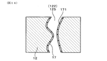
- a coat layer 17 containing a catalyst 171, alumina, a cocatalyst, and the like can be formed on the partition wall 12.
- the coat layer 17 containing the catalyst may be supported at least on the pore wall 122a, and may also be supported on the surface of the partition wall 12 (the surface of the partition wall 12 facing the cell).
- Examples of the method of supporting the catalyst 2 on the pore wall 122a include an in-wall coating method in which the catalyst-containing slurry is introduced into the communication hole 122 of the partition wall 12 by suction.
- the exhaust gas purification filter 1 can carry, for example, 0.1 to 5.0 g / L of a noble metal catalyst and 50 to 120 g / L of a coat layer.
- the partition wall 12 on which the catalyst is supported also preferably contains 5% or more of micropores 124 having a pore diameter of 10 ⁇ m or less, and has a constricted communication hole 125. Further, it is preferable that the ratio of the constricted communication holes 125 is 20% or more in the state where the catalyst is supported.
- the exhaust gas purification filter 1 is often used in a state where a coat layer containing a catalyst is supported, and it is preferable to maintain the constricted communication hole 125 of the partition wall 12 even after the coat layer is supported.
- the amount of the coat layer of 50 g / L or more is a preferable supported amount in order to satisfy future exhaust gas regulations. According to the above configuration, it is possible to improve the collection rate and suppress pressure loss even when the coat layer is supported.
- the ratio of the maximum diameter ⁇ 1 ⁇ m, the minimum diameter ⁇ 2 ⁇ m, and the constricted communication hole 125 in the state where the coat layer containing the catalyst is supported is determined according to the method based on the above-mentioned 3D model.
- the pore volume ratio of the micropores 124 is measured by the mercury intrusion method.
- the exhaust gas purification filter 1 having a low pressure loss and a high collection rate.
- the exhaust gas purification system 5 includes a hybrid drive device 3, an exhaust pipe 4, and an exhaust gas purification filter 1.
- the hybrid drive device 3 includes at least an engine E.
- the engine E is, for example, a gasoline engine.
- the hybrid drive device 3 can further include a motor M and a battery B.
- the motor M assists the drive by the engine E when the vehicle is accelerating or starting, and regenerative power is generated during inertial driving or braking.
- the battery B can be charged and discharged, and is discharged during acceleration or starting to supply electric power to drive the motor M, and charges the electric power regenerated by the motor M during inertial running or braking.
- the exhaust pipe 4 is connected to the engine E. As illustrated in FIG. 16, exhaust gas including PM2 flows in the exhaust pipe 4. In order to purify the exhaust gas, the exhaust gas purification filter 1 of the first embodiment is arranged in the exhaust pipe 4.
- PM2 includes a minute PM21 having a small particle size and a coarse PM22 having a large particle size.
- exhaust gas containing a large amount of SOF easily flows into the exhaust pipe 4, and the coarse PM22 is discharged more frequently.
- the exhaust gas purification filter 1 having the same configuration as that of the first embodiment, which is excellent in the collection performance of the coarse PM22, is arranged in the exhaust pipe 4. Therefore, the coarse PM22 discharged from the engine E of the hybrid drive device 3 can be sufficiently collected. Furthermore, since the pressure loss can be kept low, the fuel consumption is further improved.
- the coarse PM22 including SOF is less likely to cause Brownian motion. Therefore, as illustrated in FIG. 18, the coarse PM22 has a low collision probability with the pore wall 122a in the large pore 127, and is difficult to be collected by the pore wall 122a of the large pore 127.
- Example 1 In this example, the relationship between the pore volume ratio of the micropores 124 having a pore diameter of 10 ⁇ m or less, the ratio of the constricted communication holes 125, the collection rate, and the pressure loss is investigated. First, a plurality of exhaust gas purification filters 1 having different pore volume ratios of micropores 124 and constricted communication holes 125 were produced.
- the exhaust gas purification filter 1 was manufactured as follows. Specifically, first, talc, silica, and aluminum hydroxide were adjusted to have a cordierite composition after firing, and a binder, a lubricant, and water were added thereto and mixed to prepare a clay. This clay was extruded to obtain a molded product. Then, the molded product was dried to obtain a dried product having a honeycomb structure. The cells were alternately sealed on each end face so that the end faces of the dried body had a check pattern. Then, the exhaust gas purification filter 1 was obtained by firing.
- the exhaust gas purification filter 1 is a columnar shape having a diameter of 118 mm and a length in the axial direction of 120 mm.
- the cell wall thickness is 8.5 mil
- the cell density is 300 cpsi
- the cell shape in the cross section perpendicular to the axial direction is quadrangular.
- the pore volume of the fine pores 124 having a constricted communication hole 125 of 20% or more of the pore volume and a pore diameter of 10 ⁇ m or less A plurality of exhaust gas purification filters 1 having different ratios were produced. Further, a plurality of exhaust gas purification filters 1 having a pore volume ratio of the fine pores 124 of 5% and a different ratio of the constricted communication holes 125 were produced.
- Each exhaust gas purification filter 1 has an average pore diameter of 15 to 22 ⁇ m and a porosity of 60 to 70%. Porosity and average pore diameter are measured as follows.
- the porosity and the average pore diameter of the partition wall 12 of each exhaust gas purification filter 1 were measured by a mercury porosimeter using the principle of the mercury intrusion method.
- the average pore size is also called the average pore size.
- test piece for measurement was cut out from each test piece.
- the test piece is a rectangular parallelepiped having dimensions of 15 mm in length ⁇ 15 mm in width in the direction orthogonal to the axial direction Y and a length of 20 mm in the axial direction Y.
- the test piece is collected from the same 6 positions as the measurement sample of the CT scan described above, and the arithmetic mean value of these is used as the measurement result.
- the test piece was stored in the measurement cell of the mercury porosimeter, and the pressure inside the measurement cell was reduced. Then, mercury was introduced into the measurement cell and pressurized, and the pore diameter and the pore volume were measured from the pressure at the time of pressurization and the volume of mercury introduced into the pores of the test piece.
- the measurement was performed in the pressure range of 0.5 to 20000 psia.
- 0.5 psia corresponds to 0.35 ⁇ 10 -3 kg / mm 2
- 20000 psia corresponds to 14 kg / mm 2 .
- the range of the pore diameter corresponding to this pressure range is 0.01 to 420 ⁇ m.
- a contact angle of 140 ° and a surface tension of 480 dyn / cm were used as constants when calculating the pore diameter from the pressure.
- the average pore diameter is the pore diameter at an integrated value of 50% of the pore volume.
- the porosity was calculated from the following relational expression.
- the true specific gravity of cordierite is 2.52.
- Porosity (%) total pore volume / (total pore volume + 1 / true specific gravity of cordierite) x 100
- the pore volume ratio of the fine pores 124 in each exhaust gas purification filter 1, that is, the pore volume ratio of the pore diameter of 10 ⁇ m or less was measured as follows.
- the ratio of the constricted communication holes 125 of each exhaust gas purification filter 1 was measured by the method by the CT scan shown in the first embodiment.
- the collection rate and pressure loss of PM2 of each exhaust gas purification filter 1 were measured as follows.
- the exhaust gas purification filter 1 was installed in the exhaust pipe of a 2.0 L gasoline direct injection engine so that the intake air amount (Ga) was 20 g / s (steady state). Then, the exhaust gas containing PM2 was flowed into the exhaust gas purification filter 1. At this time, the PM concentration in the exhaust gas before flowing into the exhaust gas purification filter 1 and the PM concentration in the exhaust gas flowing out from the exhaust gas purification filter 1 were measured, and the collection rate of PM2 was calculated.
- the exhaust gas purification filter 1 was installed in the exhaust pipe of a 2.0 L gasoline direct injection engine so that the intake air amount (Ga) was 100 g / s (steady state). Then, the exhaust gas containing PM2 was flowed into the exhaust gas purification filter 1. At this time, the pressure before and after the exhaust gas purification filter 1 was measured, and the difference was measured as a pressure loss.
- Tables 1 and 2 show the measurement results for each exhaust gas purification filter (specifically, test specimens 1 to 25). Further, each measurement result is shown in the graphs of FIGS. 20 to 22.
- FIG. 20 shows the relationship between the pore volume ratio of the micropores 124 and the collection rate when the ratio of the constricted communication holes 125 is 20% or more or less than 20%.
- FIG. 21 shows the pore volume ratio of the micropores 124 and the result of pressure loss when the ratio of the constricted communication holes 125 is 20% or more or less than 20%.
- FIG. 22 shows the relationship between the ratio of the constricted communication holes 125 and the collection rate when the pore volume of the micropores 124 is 5%.
- the ratio of the constricted communication holes 125 is preferably 20% or more. Even if the ratio of the constricted communication holes is less than 20%, the effect of increasing the collection rate can be produced while reducing the pressure loss.
- the pressure loss gradually increases until the pore volume ratio of the fine pores reaches 25%, and the pressure loss reaches 7 kPa. Further, as the pore volume ratio of the fine pores increases, the pressure loss increases sharply.
- the ratio of the constricted communication holes is less than 20%, the pressure loss gradually increases, and when the pore volume ratio of the fine pores is 27%, the pressure loss is 7.2 kPa, which exceeds 7 kPa.
- the pore volume ratio of the fine pores 124 is preferably 25% or less, more preferably 20% or less, still more preferably 15% or less.
- the ratio of the constricted communication holes 125 is more preferably 40% or more, and further preferably 60% or more.
- the pore volume ratio of the micropores 124 is more preferably 10% or more, further preferably 21% or more.
- the exhaust gas purification filter 1 of the first embodiment is applied to the exhaust gas purification system 5 having the hybrid drive device 3, but instead of the hybrid drive device 3, for example, a diesel engine or a gasoline engine It is also possible to apply it to an exhaust gas purification system equipped with.
- the exhaust gas purification filter 1 can also be used for collecting PM emitted from an internal combustion engine other than a diesel engine or a gasoline engine.
Landscapes
- Chemical & Material Sciences (AREA)
- Engineering & Computer Science (AREA)
- Chemical Kinetics & Catalysis (AREA)
- Combustion & Propulsion (AREA)
- Geometry (AREA)
- Physics & Mathematics (AREA)
- Mechanical Engineering (AREA)
- General Engineering & Computer Science (AREA)
- Health & Medical Sciences (AREA)
- Materials Engineering (AREA)
- Organic Chemistry (AREA)
- Inorganic Chemistry (AREA)
- Ceramic Engineering (AREA)
- Life Sciences & Earth Sciences (AREA)
- General Chemical & Material Sciences (AREA)
- Oil, Petroleum & Natural Gas (AREA)
- Environmental & Geological Engineering (AREA)
- Biomedical Technology (AREA)
- Geology (AREA)
- Analytical Chemistry (AREA)
- Toxicology (AREA)
- Filtering Materials (AREA)
- Processes For Solid Components From Exhaust (AREA)
- Porous Artificial Stone Or Porous Ceramic Products (AREA)
- Exhaust Gas Treatment By Means Of Catalyst (AREA)
- Catalysts (AREA)
- Filtering Of Dispersed Particles In Gases (AREA)
Priority Applications (3)
| Application Number | Priority Date | Filing Date | Title |
|---|---|---|---|
| CN202080017803.1A CN113507976A (zh) | 2019-03-29 | 2020-02-18 | 废气净化过滤器 |
| EP20783826.9A EP3919153A4 (en) | 2019-03-29 | 2020-02-18 | Exhaust gas purification filter |
| US17/487,254 US11840949B2 (en) | 2019-03-29 | 2021-09-28 | Exhaust gas purification filter |
Applications Claiming Priority (2)
| Application Number | Priority Date | Filing Date | Title |
|---|---|---|---|
| JP2019-068771 | 2019-03-29 | ||
| JP2019068771A JP2020163336A (ja) | 2019-03-29 | 2019-03-29 | 排ガス浄化フィルタ |
Related Child Applications (1)
| Application Number | Title | Priority Date | Filing Date |
|---|---|---|---|
| US17/487,254 Continuation US11840949B2 (en) | 2019-03-29 | 2021-09-28 | Exhaust gas purification filter |
Publications (1)
| Publication Number | Publication Date |
|---|---|
| WO2020202851A1 true WO2020202851A1 (ja) | 2020-10-08 |
Family
ID=72668835
Family Applications (1)
| Application Number | Title | Priority Date | Filing Date |
|---|---|---|---|
| PCT/JP2020/006216 Ceased WO2020202851A1 (ja) | 2019-03-29 | 2020-02-18 | 排ガス浄化フィルタ |
Country Status (5)
| Country | Link |
|---|---|
| US (1) | US11840949B2 (enExample) |
| EP (1) | EP3919153A4 (enExample) |
| JP (1) | JP2020163336A (enExample) |
| CN (1) | CN113507976A (enExample) |
| WO (1) | WO2020202851A1 (enExample) |
Citations (4)
| Publication number | Priority date | Publication date | Assignee | Title |
|---|---|---|---|---|
| US20030054154A1 (en) * | 2001-09-14 | 2003-03-20 | Hancun Chen | Method of making a porous green form and oxygen transport membrane |
| JP2008545612A (ja) * | 2005-05-31 | 2008-12-18 | コーニング インコーポレイテッド | 細孔形成剤の組合せを含有するチタン酸アルミニウムセラミック形成バッチ混合物および未焼成体、および同混合物および未焼成体の製造および焼成方法 |
| WO2011115181A1 (ja) * | 2010-03-19 | 2011-09-22 | 住友化学株式会社 | ハニカム構造体の製造方法及びハニカム構造体、並びにパティキュレートフィルタ |
| WO2011125797A1 (ja) * | 2010-04-01 | 2011-10-13 | 日立金属株式会社 | セラミックハニカムフィルタ及びその製造方法 |
Family Cites Families (16)
| Publication number | Priority date | Publication date | Assignee | Title |
|---|---|---|---|---|
| JP4094830B2 (ja) | 2000-11-24 | 2008-06-04 | 日本碍子株式会社 | 多孔質ハニカムフィルター及びその製造方法 |
| JP3925225B2 (ja) | 2001-03-28 | 2007-06-06 | 株式会社デンソー | 排ガス浄化フィルタ及びその製造方法 |
| US20040161596A1 (en) | 2001-05-31 | 2004-08-19 | Noriyuki Taoka | Porous ceramic sintered body and method of producing the same, and diesel particulate filter |
| JP2004188303A (ja) | 2002-12-10 | 2004-07-08 | Ngk Insulators Ltd | セラミックハニカムフィルタ |
| KR100794541B1 (ko) * | 2004-06-30 | 2008-01-17 | 이비덴 가부시키가이샤 | 배기가스 정화 장치 |
| JP4473693B2 (ja) | 2004-09-28 | 2010-06-02 | 日本碍子株式会社 | ハニカムフィルタ |
| JP5444716B2 (ja) * | 2006-11-30 | 2014-03-19 | 日立金属株式会社 | セラミックハニカムフィルタ及びその製造方法 |
| EP2335797B1 (en) * | 2008-07-28 | 2019-03-06 | Hitachi Metals, Ltd. | Ceramic honeycomb structure |
| US20120003464A1 (en) * | 2009-01-07 | 2012-01-05 | Sumitomo Chemical Company, Limited | Porous ceramics shaped body, and process for producing same |
| JP4920752B2 (ja) | 2010-01-05 | 2012-04-18 | 日本碍子株式会社 | ハニカム構造体 |
| JP5518518B2 (ja) * | 2010-02-15 | 2014-06-11 | 日本碍子株式会社 | ハニカムフィルタの製造方法 |
| KR20140009443A (ko) * | 2011-03-31 | 2014-01-22 | 스미또모 가가꾸 가부시끼가이샤 | 허니콤 구조체 |
| WO2013109820A1 (en) * | 2012-01-20 | 2013-07-25 | Dow Global Technologies Llc | Ceramic filter for exhaust gas particulates having asymmetric channels |
| JP6081831B2 (ja) * | 2012-03-19 | 2017-02-15 | 日本碍子株式会社 | ハニカム構造体およびこれを用いたハニカム触媒体、ならびにハニカム構造体の製造方法 |
| JP6114023B2 (ja) | 2012-12-18 | 2017-04-12 | 日本碍子株式会社 | 微粒子捕集フィルタ |
| JP5990095B2 (ja) | 2012-12-18 | 2016-09-07 | 日本碍子株式会社 | 微粒子捕集フィルタ |
-
2019
- 2019-03-29 JP JP2019068771A patent/JP2020163336A/ja active Pending
-
2020
- 2020-02-18 CN CN202080017803.1A patent/CN113507976A/zh active Pending
- 2020-02-18 EP EP20783826.9A patent/EP3919153A4/en not_active Withdrawn
- 2020-02-18 WO PCT/JP2020/006216 patent/WO2020202851A1/ja not_active Ceased
-
2021
- 2021-09-28 US US17/487,254 patent/US11840949B2/en active Active
Patent Citations (4)
| Publication number | Priority date | Publication date | Assignee | Title |
|---|---|---|---|---|
| US20030054154A1 (en) * | 2001-09-14 | 2003-03-20 | Hancun Chen | Method of making a porous green form and oxygen transport membrane |
| JP2008545612A (ja) * | 2005-05-31 | 2008-12-18 | コーニング インコーポレイテッド | 細孔形成剤の組合せを含有するチタン酸アルミニウムセラミック形成バッチ混合物および未焼成体、および同混合物および未焼成体の製造および焼成方法 |
| WO2011115181A1 (ja) * | 2010-03-19 | 2011-09-22 | 住友化学株式会社 | ハニカム構造体の製造方法及びハニカム構造体、並びにパティキュレートフィルタ |
| WO2011125797A1 (ja) * | 2010-04-01 | 2011-10-13 | 日立金属株式会社 | セラミックハニカムフィルタ及びその製造方法 |
Non-Patent Citations (1)
| Title |
|---|
| See also references of EP3919153A4 * |
Also Published As
| Publication number | Publication date |
|---|---|
| EP3919153A8 (en) | 2022-03-16 |
| CN113507976A (zh) | 2021-10-15 |
| EP3919153A1 (en) | 2021-12-08 |
| US20220018273A1 (en) | 2022-01-20 |
| EP3919153A4 (en) | 2022-03-30 |
| US11840949B2 (en) | 2023-12-12 |
| JP2020163336A (ja) | 2020-10-08 |
Similar Documents
| Publication | Publication Date | Title |
|---|---|---|
| JP6219796B2 (ja) | ハニカムフィルタ | |
| CN106351718B (zh) | 废气过滤器 | |
| JP5859752B2 (ja) | 排ガス浄化フィルタ | |
| JP6788515B2 (ja) | 目封止ハニカム構造体 | |
| CN108571356A (zh) | 封孔蜂窝结构体 | |
| JP2019171318A (ja) | ハニカムフィルタ | |
| JP5829840B2 (ja) | 排ガス浄化フィルタ | |
| JP2019177317A (ja) | ハニカムフィルタ | |
| JP2016052635A (ja) | ハニカムフィルタ | |
| JP2015066536A (ja) | 触媒担持型ハニカムフィルタ | |
| JP2019177318A (ja) | ハニカムフィルタ | |
| JP2019177316A (ja) | ハニカムフィルタ | |
| JP2012213755A (ja) | ハニカム構造体及びハニカム触媒体 | |
| JP5368770B2 (ja) | ハニカム構造体及びその製造方法、並びにハニカム触媒体 | |
| JP2014148924A (ja) | 排ガス浄化装置 | |
| WO2020202851A1 (ja) | 排ガス浄化フィルタ | |
| JP2010104956A (ja) | ハニカム構造体、並びにハニカム触媒体 | |
| JP7230671B2 (ja) | 排ガス浄化フィルタ | |
| CN218934533U (zh) | 蜂窝过滤器 | |
| JP6091282B2 (ja) | 触媒コートフィルタ及び触媒コートフィルタ用担体 | |
| JP7097327B2 (ja) | 排ガス浄化フィルタ | |
| JP6956139B2 (ja) | 排ガス浄化フィルタ | |
| US11529578B2 (en) | Exhaust gas purification filter | |
| US20250073640A1 (en) | Exhaust gas purification device | |
| CN114917694A (zh) | 封孔蜂窝结构体 |
Legal Events
| Date | Code | Title | Description |
|---|---|---|---|
| 121 | Ep: the epo has been informed by wipo that ep was designated in this application |
Ref document number: 20783826 Country of ref document: EP Kind code of ref document: A1 |
|
| ENP | Entry into the national phase |
Ref document number: 2020783826 Country of ref document: EP Effective date: 20210831 |
|
| NENP | Non-entry into the national phase |
Ref country code: DE |