WO2020202309A1 - 建設機械の駆動装置 - Google Patents
建設機械の駆動装置 Download PDFInfo
- Publication number
- WO2020202309A1 WO2020202309A1 PCT/JP2019/014157 JP2019014157W WO2020202309A1 WO 2020202309 A1 WO2020202309 A1 WO 2020202309A1 JP 2019014157 W JP2019014157 W JP 2019014157W WO 2020202309 A1 WO2020202309 A1 WO 2020202309A1
- Authority
- WO
- WIPO (PCT)
- Prior art keywords
- flow rate
- hydraulic
- pump
- hydraulic actuators
- distribution
- Prior art date
- Legal status (The legal status is an assumption and is not a legal conclusion. Google has not performed a legal analysis and makes no representation as to the accuracy of the status listed.)
- Ceased
Links
Images






Classifications
-
- E—FIXED CONSTRUCTIONS
- E02—HYDRAULIC ENGINEERING; FOUNDATIONS; SOIL SHIFTING
- E02F—DREDGING; SOIL-SHIFTING
- E02F9/00—Component parts of dredgers or soil-shifting machines, not restricted to one of the kinds covered by groups E02F3/00 - E02F7/00
- E02F9/20—Drives; Control devices
-
- E—FIXED CONSTRUCTIONS
- E02—HYDRAULIC ENGINEERING; FOUNDATIONS; SOIL SHIFTING
- E02F—DREDGING; SOIL-SHIFTING
- E02F9/00—Component parts of dredgers or soil-shifting machines, not restricted to one of the kinds covered by groups E02F3/00 - E02F7/00
- E02F9/20—Drives; Control devices
- E02F9/22—Hydraulic or pneumatic drives
-
- F—MECHANICAL ENGINEERING; LIGHTING; HEATING; WEAPONS; BLASTING
- F15—FLUID-PRESSURE ACTUATORS; HYDRAULICS OR PNEUMATICS IN GENERAL
- F15B—SYSTEMS ACTING BY MEANS OF FLUIDS IN GENERAL; FLUID-PRESSURE ACTUATORS, e.g. SERVOMOTORS; DETAILS OF FLUID-PRESSURE SYSTEMS, NOT OTHERWISE PROVIDED FOR
- F15B11/00—Servomotor systems without provision for follow-up action; Circuits therefor
- F15B11/02—Systems essentially incorporating special features for controlling the speed or actuating force of an output member
-
- F—MECHANICAL ENGINEERING; LIGHTING; HEATING; WEAPONS; BLASTING
- F15—FLUID-PRESSURE ACTUATORS; HYDRAULICS OR PNEUMATICS IN GENERAL
- F15B—SYSTEMS ACTING BY MEANS OF FLUIDS IN GENERAL; FLUID-PRESSURE ACTUATORS, e.g. SERVOMOTORS; DETAILS OF FLUID-PRESSURE SYSTEMS, NOT OTHERWISE PROVIDED FOR
- F15B11/00—Servomotor systems without provision for follow-up action; Circuits therefor
- F15B11/16—Servomotor systems without provision for follow-up action; Circuits therefor with two or more servomotors
- F15B11/17—Servomotor systems without provision for follow-up action; Circuits therefor with two or more servomotors using two or more pumps
Definitions
- the present invention relates to a drive device for a construction machine.
- Patent Document 1 there is a technique described in Patent Document 1, for example, as a consideration for throttle pressure loss generated in a control valve of a hydraulic system or the like. This is based on an operation signal to the hydraulic actuator generated by the operating device by connecting a plurality of hydraulic pumps and a plurality of hydraulic actuators in a closed circuit via an electromagnetic switching valve that communicates or shuts off the flow path instead of a control valve. The speed of each hydraulic actuator is controlled by setting the connection between the plurality of hydraulic pumps and the plurality of hydraulic actuators by the electromagnetic switching valves and changing the discharge flow rate of the hydraulic pumps.
- the hydraulic pump may be damaged due to the time required for the excessive absorption power to act on the hydraulic pump. Further, in the above-mentioned conventional technique, when the discharge flow rate of the hydraulic pump is restricted after the fact, the speed of the actuator having a high load is lowered after the distribution flow rate is determined, so that the distribution flow rate ratio collapses. Therefore, there is a problem that the operability is lowered.
- the present invention has been made in view of the above, and an object of the present invention is to provide a drive device for a construction machine capable of appropriately limiting the absorption power of a hydraulic pump and suppressing a decrease in operability. And.
- the present application includes a plurality of means for solving the above problems.
- a plurality of hydraulic actuators and each of the plurality of hydraulic actuators are connected to each other via a plurality of oil passages to operate an operating device.
- a plurality of pump devices that discharge pressure oil according to the amount and pressure oil that is provided in each of the plurality of oil passages and is discharged from the plurality of pump devices are selectively supplied to the plurality of hydraulic actuators.
- a drive device of a construction machine including a plurality of hydraulic valves for switching the flow of the plurality of oil passages and a controller for controlling the pump device and the hydraulic valve according to the operation amount of the operating device, the controller.
- the plurality of pressure oils are supplied from the plurality of hydraulic actuators in accordance with the pressure of the pressure oil supplied to the plurality of hydraulic actuators and the limiting power predetermined as the upper limit value of the absorption power of each of the plurality of pump devices.
- the pump limit flow rate which is the upper limit of the pump flow rate that can be discharged to each of the hydraulic actuators, is calculated, and the required flow rates of the plurality of hydraulic actuators are calculated according to the operation amount of the operating device, and the required flow rate and the pump are calculated.
- the distributed flow rate of the pressure oil supplied to the plurality of hydraulic actuators is calculated based on the limited flow rate, and the discharge flow rate of each of the plurality of pump devices is calculated according to the distributed flow rate.
- the absorption power of the hydraulic pump can be appropriately limited, and the deterioration of operability can be suppressed.
- FIGS. 1 to 12 a hydraulic excavator having a bucket 3 at the tip of a work machine (front work device) as a construction machine is illustrated, but the present invention can also be applied to a hydraulic excavator having an attachment other than the bucket. is there. Further, it can be applied to construction machinery other than hydraulic excavators as long as it has a hydraulic system that controls the connection relationship between a plurality of hydraulic actuators and a plurality of hydraulic pumps.
- an alphabet may be added to the end of the code (number), but the alphabet may be omitted and the plurality of components may be collectively described. is there. That is, for example, when four hydraulic pumps 10a, 10b, 10c, and 10c are present, they may be collectively referred to as the hydraulic pump 10. Further, for the sake of simplicity, the illustration of signal lines and the like whose connection relationship is clear by explanation may be omitted.
- FIG. 1 is a diagram showing a driving device of a hydraulic excavator together with a control device thereof.
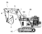
- FIG. 2 is a diagram showing the appearance of a hydraulic excavator as an example of a construction machine to which the present invention is applied. Note that FIG. 1 shows a standby state (when there is no lever operation).
- the hydraulic excavator to which the present invention is applied is a gearbox 9 for transmitting a driving force composed of torque and rotation speed input to the shaft 8a to a plurality of shafts 9a to 9d, and an engine via the gearbox 9.
- Hydraulic pumps 10a to 10d which are double tilt variable capacitance type and have two input / output ports, driven by a prime mover 8 such as an electric motor or an electric motor, and one-sided tilt fixed driven by the prime mover 8 via a power transmission mechanism (not shown).
- a plurality of hydraulic actuators such as a boom cylinder 4, an arm cylinder 5, a bucket cylinder 6, and a swivel motor 7 driven by the above, and a plurality of pipes connecting the plurality of hydraulic pumps 10a to 10d and the plurality of hydraulic actuators 4 to 7, respectively.
- a plurality of hydraulic actuators 4 to 7 provided on the passage (oil passage) to switch the supply destination of the pressure oil discharged from the plurality of hydraulic pumps 10a to 10d based on the control signal (valve command).
- Hydraulic valve groups 12a to 12d Hydraulic valve groups 12a to 12d, a plurality of operating levers (operating devices) L1 and L2 for operating a plurality of hydraulic actuators 4 to 7, and an operating amount (lever operating amount) of the operating levers L1 and L2 operated by the operator.
- a controller 27 that controls the hydraulic valve groups 12a to 12d and the regulators 11a to 11d based on the detection results of a pressure sensor (not shown), and a traveling motor (not shown), which are driven members of the hydraulic excavator. It constitutes a hydraulic drive system to drive.
- the hydraulic pumps 10a to 10d and the regulators 11a to 11d constitute a plurality of pump devices that discharge pressure oil according to the operation amount of the operation devices L1 and L2 operated by the operator. For the sake of simplicity, the maximum discharge flow rates of the hydraulic pumps 10a to 10d will be described as being equal.
- the hydraulic valve groups 12a to 12d are for connecting a plurality of hydraulic actuators 4 to 7 and at least one or more hydraulic pumps 10a to 10d in a hydraulically closed circuit, and are used as control signals (valve commands) from the controller 27. Based on this, the connection state of the pipeline is switched so that the pressure oil discharged from the hydraulic pumps 10a to 10d is supplied to any one of the plurality of hydraulic actuators.
- the hydraulic valve group 12a selectively switches the connection so that the hydraulic pump 10a forms a closed circuit with any one of the plurality of hydraulic actuators 4 to 7, and is composed of the plurality of hydraulic valves 13a to 16a.
- the hydraulic valves 13a to 16a are electromagnetic switching valves for switching the cutoff or communication of the pipeline based on the control signal from the controller 27, and the hydraulic valves 13a to 16a are the hydraulic pump 10a and the plurality of hydraulic actuators 4 to 7, respectively. Toggle closed circuit connection interruption or communication.
- the hydraulic valve 13a is the hydraulic pump 10a and the boom cylinder 4
- the hydraulic valve 14a is the hydraulic pump 10a and the arm cylinder 5
- the hydraulic valve 15a is the hydraulic pump 10a and the bucket cylinder 6
- the hydraulic valve 16a is the hydraulic pump 10a and the swivel motor 7.
- Toggle closed circuit connection interruption or communication For example, when the hydraulic valve 13a is controlled to be in the open state and the other hydraulic valves 14a to 16a are controlled to be in the closed state, the hydraulic pump 10a and the boom cylinder 4 are connected in a closed circuit.
- the hydraulic valves 13a to 16a are normally closed type electromagnetic switching valves that shut off the pipeline in a standby state in which no control signal is input, and communicate the pipeline when a control signal as a valve opening command is input from the controller 27. To do.
- the other hydraulic valve groups 12b to 12d are the same as those of the hydraulic valve group 12a. That is, the hydraulic valve groups 12b to 12d are composed of a plurality of hydraulic valves 13b to 16b, 13c to 16c, 13d to 16d which are electromagnetic switching valves, and the hydraulic pumps 10b to 10d are based on the control signal from the controller 27. The closed circuit connection between each of the above and the plurality of hydraulic actuators 4 to 7 is cut off or switched.
- the charge pipeline 21a to which the pressure oil is supplied from the charge pump 21 is provided with a charge relief valve 26 that releases excess pressure oil to the pressure oil tank 22 while maintaining the pressure of the charge pipeline 21a at a set pressure.
- the charge relief valve 26 determines the maximum pressure of the charge line 21a.
- pressure sensors 4a, ..., 7b for detecting the pressure of the pressure oil supplied to the hydraulic actuators 4 to 7 are located downstream of the hydraulic valve groups 12a to 12d of the hydraulic closed circuit of the hydraulic actuators 4 to 7. It is provided.
- pressure sensors 4a, 5a, 6a are provided on the rod chamber side of the hydraulic cylinders 4 to 6, and pressure sensors 4b, 5b, 6b are provided on the head chamber side, respectively.
- pressure sensors 7a and 7b are provided in both pipelines connected to the swivel motor 7.
- the hydraulic excavator includes an articulated front device 1A configured by connecting a boom 1, an arm 2, and a bucket 3 that rotate in the vertical direction, an upper swing body 1B, and a lower portion. It is composed of a traveling body 1C.
- the base end of the boom 1 of the front device 1A is rotatably supported by the front portion of the upper swing body 1B, and one end of the arm 2 can be rotatably supported at an end (tip) different from the base end of the boom 1. It is supported, and a bucket 3 is rotatably supported at the other end of the arm 2.
- the boom 1, arm 2, bucket 3, upper swivel body 1B, and lower traveling body C are each driven by a boom cylinder 4, an arm cylinder 5, a bucket cylinder 6, a swivel motor 7, and left and right traveling motors (not shown).
- the driver's cab 101 on which the operator is boarding is provided with operation levers (operation devices) L1 and L2 for outputting operation signals for operating the hydraulic actuators 4 to 7.
- the operation levers L1 and L2 can be tilted back and forth and left and right, and include a detection device (not shown) that electrically detects the tilt amount of the lever, which is an operation signal, that is, the lever operation amount, and the lever detected by the detection device.
- the operation amount is output to the controller 27, which is a control device, via electrical wiring. That is, in the present embodiment, the operations of the hydraulic actuators 4 to 7 are assigned to the operation levers L1 and L2 in the front-rear direction or the left-right direction, respectively.
- FIG. 3 is a functional block diagram showing the processing function of the controller. Further, FIG. 4 is a functional block diagram showing a processing function of the flow rate distribution unit of the controller.
- the controller 27 includes a required flow rate calculation unit 31 that calculates the required flow rate (in other words, the required speed) of the plurality of hydraulic actuators 4 to 7 according to the lever operation amount input from the operation levers L1 and L2, and the hydraulic pressure.
- Pumps 10a to 10d preset with a predetermined margin with respect to the limit power defined as the limit value of absorption power represented by the product of the acting pressure and the discharge flow rate (that is, the durability value of the hydraulic pumps 10a to 10d). Based on the pump limiting power setting unit 35 in which the pump limiting power which is the limit value is stored, and the actuator pressure and the pump limiting power input from the pressure sensors 4a, ..., 7b of the plurality of hydraulic actuators 4 to 7.
- the pump limit flow rate calculation unit 34 that calculates the pump limit flow rate for each of the hydraulic actuators 4 to 7 and the flow rate of the pressure oil supplied to the plurality of hydraulic actuators 4 to 7 based on the required flow rate and the pump limit flow rate (hereinafter,
- the flow distribution unit 32 that calculates the distribution flow rate) calculates the discharge flow rate of each of the plurality of hydraulic pumps 10a to 10d based on the distribution flow rate and the pump limit flow rate, and controls the plurality of hydraulic pumps 10a to 10d. It includes a pump allocation calculation unit 33 that outputs a signal (pump command) and a control signal (pump command) to the hydraulic valve groups 12a to 12d.
- the flow rate distribution unit 32 has a plurality of hydraulic pumps 10a to 10d for at least two hydraulic actuators (for example, the boom cylinder 4 and the arm cylinder 5) driven by a combined operation among the plurality of hydraulic actuators 4 to 7.
- a distributable area 52 is set to calculate a range of distributable flow rates, which is the flow rate of pressure oil that can be supplied to at least two hydraulic actuators, and is supplied to at least two hydraulic actuators in the distributable area 52.
- the distribution area 53 includes the distribution area setting unit 41 for setting the distribution area 53 for calculating the distribution flow rate of the hydraulic oil, and the distribution area 53 when at least the required flow rate is outside the range of the distributable area 52.
- the ratio distribution unit 42 that calculates the distribution flow rate so that the ratio of the distribution flow rate between the at least two hydraulic actuators becomes equal to the ratio of the required flow rate is provided.
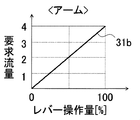
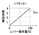
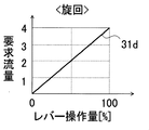
- 5A to 5D are diagrams showing the relationship between the operation amount of the operation lever used in the required flow rate calculation unit and the required flow rate.
- 5A to 5D show the relationship between the lever operation amount in the direction corresponding to the boom cylinder 4 and the required flow rate of the boom cylinder 4, respectively, and FIG. 5B shows the lever operation amount and the arm cylinder in the direction corresponding to the arm cylinder 5.
- 5C shows the relationship between the lever operation amount in the direction corresponding to the bucket cylinder 6 and the required flow rate of the bucket cylinder 6, and
- FIG. 5D shows the lever operation in the direction corresponding to the swivel motor 7.
- the relationship between the amount and the required flow rate of the swivel motor 7 is shown.
- the required flow rate 31a to 31d is stored in the required flow rate calculation unit 31 in advance, and is stored from the operation levers L1 and L2. It is used when calculating the required flow rate of the hydraulic actuators 4 to 7 according to the input lever operation amount.
- the distributable area is theoretically set to calculate the range of the flow rate of the pressure oil that can be supplied to the actuator, and the distribution area for calculating the range of the distribution flow rate actually supplied to the hydraulic actuator is Set to be included in the allocatable area.
- the allocation area is set so as to be within the range of the distributable area, and an arbitrary range of the distributable area can be set in advance as needed. In the present embodiment, a case where a distribution area in the same range as the distributable area is set in the distribution area setting unit 41 is illustrated. In addition, various other ranges can be considered as the distribution area set in the distribution area setting unit 41.
- the maximum value within the range of the distribution area of the sum of the distribution flow rates set in the plurality of hydraulic actuators is a plurality.
- the distribution area is set so as to be constant regardless of the ratio of the required flow rates between the hydraulic actuators, and as the lever operation amount (required flow rate) related to the boom cylinder 4 increases from the value indicating fine operation,
- the distribution area can be set so that the speed of the arm cylinder 5 tends to decrease (in other words, the reduction rate of the distribution flow rate increases).
- the distributable region is a region of the distributable flow rate defined based on the distributable flow rate, which is the flow rate of the pressure oil that can be supplied from the plurality of hydraulic pumps 10a to 10b to the plurality of hydraulic actuators 4 to 7.
- the distributable region includes a combination in which a plurality of hydraulic pumps 10a to 10b and a plurality of hydraulic actuators 4 to 7 can be connected in a closed circuit by the hydraulic valve groups 12a to 12d, and a dischargeable flow rate of the plurality of hydraulic pumps 10a to 10b.
- the calculation of the discharge flow rate of the hydraulic pumps 10a to 10d in the pump allocation calculation unit 33 includes the pump allocation which is the allocation of the hydraulic pumps 10a to 10d for supplying the pressure oil to the hydraulic actuators 4 to 7 at the same time.
- FIG. 6 is a diagram showing an example of a priority connection table used in the pump allocation calculation unit.
- the priority connection table 33a defines the priority of connection of the hydraulic pumps 10a to 10d to the hydraulic actuators 4 to 7, and determines the distributed flow rate of the hydraulic actuators 4 to 7 calculated by the flow rate distribution unit 32. This is a standard for determining which hydraulic pumps 10a to 10d are supplied from.
- the priority connection table 33a shows the priority of the hydraulic pump as seen from the hydraulic actuator side, and also shows the priority of the hydraulic actuator as seen from the hydraulic pump side. For example, when viewed from the hydraulic actuator side, the hydraulic pump 10a as seen from the boom cylinder 4 has the first priority, and the hydraulic pump 10d has the fourth priority. Seen from the hydraulic pump side, for example, the boom cylinder 4 as seen from the hydraulic pump 10a has the highest priority, and the swivel motor 7 has the fourth priority.
- the pump allocation calculation unit 33 calculates the pump allocation and discharge flow rate of the hydraulic pumps 10a to 10d based on the distribution flow rate calculated by the flow rate distribution unit 32, the pump limit flow rate, and the priority connection table, and the pump allocation calculation unit 33 calculates the pump allocation and discharge flow rate of the hydraulic pumps 10a to 10d.
- Each discharge flow rate is output as a control signal (pump command), and the connection setting of the closed circuit connection between the hydraulic actuators 4 to 7 and the hydraulic pumps 10a to 10d according to the pump allocation is controlled to the hydraulic valve groups 12a to 12d. Output as a signal (valve command).
- FIG. 7 is a flowchart showing the processing contents of the pump limit flow rate calculation unit.
- the pump limiting flow rate calculation unit 34 first includes actuator pressures Pa_1, ..., Pa_N (N is a positive integer) detected by the pressure sensors 4a, ..., 7b, and a pump limiting power setting unit.
- the pump limiting power Wplim set in 35 is read (step S100).
- the maximum discharge flow rate of 10d is normalized as 1 (step S120).
- the normalized pump limit flow rate Qaplim_i 1 (that is, 1 is the maximum value). It is assumed that the hydraulic pumps 10a to 10d are of the same type (same product), and the pump limiting power Wplim is also the same.
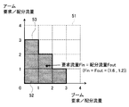
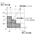
- FIGS. 10 to 12 are diagrams for conceptually explaining the relationship between the required flow rate and the distributed flow rate, and is a diagram showing a case where a combined operation of the arm cylinder and the boom cylinder is considered as an example.
- the case where the discharge flow rate of the above is limited that is, the case where the pump limit flow rate ⁇ 1) and the required flow rate takes a value outside the range of the allocation region is shown.
- the 10 to 12 show the required flow rate and the distributed flow rate for each hydraulic actuator on each axis of the coordinate system
- the vertical axis shows the required flow rate and the distributed flow rate of the arm cylinder 5
- the horizontal axis shows the required flow rate of the boom cylinder 4.
- the distribution flow rate are shown respectively.
- the values of the required flow rate and the distributed flow rate represent the number of flow rates of the hydraulic pump with the maximum flow rate. For example, when the value of the required flow rate (or distributed flow rate) is 1.5, the required flow rate (or distributed flow rate) represents the flow rate of 1.5 hydraulic pumps with the maximum flow rate. Further, in FIGS.
- a requestable area 51 which is a range of values that the required flow rate of each hydraulic cylinder can take
- a distributable area 52 hatchched area
- a distribution area 53 area surrounded by a thick line
- FIGS. 10 to 12 are not shown in order to consider the combined operation of the arm cylinder and the boom cylinder, the range of values 3 to 4 on the vertical axis and the horizontal axis is also in consideration of the independent operation of the hydraulic actuators 4 to 7. This is the area where pressure oil is supplied to the relevant hydraulic actuator.
- the flow rate distribution unit 32 first divides the required flow rate Fin input from the required flow rate calculation unit 31 by the pump limit flow rate for each hydraulic actuator 4 to 7 input from the pump limit flow rate calculation unit 34. It is set as the required flow rate Fin for calculation (step S200). Subsequently, it is determined whether or not the required flow rate Fin due to the combined operation of the arm cylinder and the boom cylinder is within the range (including the boundary) of the distribution area 53 (step S210). If the determination result in step S210 is YES, the required flow rate Fin is set as the calculation result of the distribution flow rate Fout (step S211).
- step S210 when the determination result in step S210 is NO, that is, when the required flow rate Fin is outside the range of the distribution area 53, the straight line L passing through the origin of the coordinate system and the required flow rate Fin is calculated (step SS220). , The intersection of the straight line L and the boundary of the distribution area 53 is set as the calculation result of the distribution flow rate Fout (step S230).
- step S230 the distribution flow rate Fout set in step S211 or step S230 multiplied by the pump limit flow rate is set as the distribution flow rate Fout as the calculation result of the flow rate distribution unit 32 (step S240). ), End the process.
- the distributed flow rate Fout can be determined by a simpler calculation by calculating the distributed flow rate Fout in steps S210 to S240 based on the result of dividing the required flow rate Fin by the pump limit flow rate in step S200. ..
- the pump allocation calculation unit 33 first sets the distribution flow rate calculated by the flow rate distribution unit 32 to the remaining distribution flow rate (step S130). Subsequently, the remaining distributed flow rate is temporarily assigned according to the priority seen from the hydraulic actuator side (step S140), and then the allocation of the hydraulic pump is adjusted according to the priority seen from the hydraulic pump side, and the allocation is made.
- the overlapping hydraulic pumps are assigned to the hydraulic actuator side having a higher priority when viewed from the hydraulic pump side (step S150). Subsequently, the remaining distributed flow rate minus the distributed flow rate (the distributed flow rate for which the hydraulic pump allocation is completed) is newly updated as the remaining distributed flow rate (step S160).
- step S170 it is determined whether or not the remaining distribution flow rates are all zero (step S170), and if the determination result is YES, the process ends. If the determination result in step S170 is NO, it is determined whether or not there is a remaining pump (hydraulic pump whose allocation has not been determined) (step S180), and if the determination result is NO, step S140 is performed. The process returns to the process, and if the determination result is YES, the process ends.
- the hydraulic pumps 10a to 10d assigned to discharge the pressure oil to the hydraulic actuators 4 to 7 set to the pump limit flow rate ⁇ 1 in the pump limit flow rate calculation unit 34 Multiply the distributable flow rate by the pump limit flow rate.
- the required flow rate Fin (1.6, 1.2) is within the range (including the boundary) of the distribution area 53, the required flow rate Fin is output as it is as the distribution flow rate Fout.
- the flow rate distribution unit 32 performs the same processing as when the distributable area 52 is converted to 0.8 times on the arm cylinder side based on the pump limited flow rate.
- the distributed flow rate of the arm cylinder is 1.6
- Priority 1st and 2nd from the hydraulic actuator side) are tentatively assigned.
- the hydraulic pump 10c Since the remaining distributed flow rates are not all zero, the hydraulic pump 10c is temporarily assigned to the remaining distributed flow rate of the arm cylinder 5 as the remaining pump, and since there is no duplication of the temporarily assigned hydraulic pumps, the priority is given from the hydraulic pump side. There is no need to adjust the allocation based on it, and the allocation is confirmed.
- the calculation result is output as a control signal (pump command) to the hydraulic pumps 10a to 10d and a control signal (valve command) to the hydraulic valve groups 12a to 12d.
- the discharge flow rate of the hydraulic pump is limited by limiting the distributed flow rate to control the absorbed power to the limit power or less
- the present invention is not limited to this, and the engine 8
- the discharge flow rate of the hydraulic pump may be limited to control the absorbed power to the limit power or less.
- the pressure of the pressure oil supplied to the plurality of hydraulic actuators 4 to 7 and the limiting power set in advance as the upper limit values of the absorption powers of the plurality of hydraulic pumps 10a to 10d are used.
- the pump limit flow rate which is the upper limit of the pump flow rate that can be discharged from each of the plurality of hydraulic actuators 4 to 7 from the plurality of hydraulic pumps 10a to 10d, is calculated according to the operation amount of the operating levers L1 and L2.
- the required flow rates of the plurality of hydraulic actuators 4 to 7 are calculated, and the distribution flow rate of the pressure oil supplied to the plurality of hydraulic actuators 4 to 7 is calculated based on the required flow rate and the pump limit flow rate. Since the discharge flow rate of each of the hydraulic pumps 10a to 10d is calculated, the absorption power of the hydraulic pump can be appropriately limited, and the deterioration of operability can be suppressed.
- the plurality of hydraulic actuators for example, boom cylinder 4, arm cylinder 5, bucket cylinder 6, swivel motor 7
- each of the plurality of hydraulic actuators and a plurality of oil passages
- a plurality of pump devices for example, hydraulic pumps 10a to 10d
- a plurality of hydraulic valves for example, hydraulic valve groups 12a to 12d that switch the flow of the plurality of oil passages so that the pressure oil discharged from the plurality of pump devices is selectively supplied to the plurality of hydraulic actuators.
- the controller is a pressure oil supplied to the plurality of hydraulic actuators.
- the pump flow rate that can be discharged from the plurality of pump devices to each of the plurality of hydraulic actuators according to the pressure and the limiting power predetermined as the upper limit of the absorption power of each of the plurality of pump devices.
- a certain pump limited flow rate is calculated, and the required flow rate of the plurality of hydraulic actuators is calculated according to the operation amount of the operating device, and is supplied to the plurality of hydraulic actuators based on the required flow rate and the pump limited flow rate.
- the distributed flow rate of the pressure oil was calculated, and the discharge flow rate of each of the plurality of pump devices was calculated according to the distributed flow rate.
- the absorption power of the hydraulic pump can be appropriately limited, and the deterioration of operability can be suppressed.
- the controller 27 is a plurality of hydraulic actuators (for example, boom cylinder 4, arm cylinder 5, bucket cylinder 6, swivel motor).
- the flow rate of pressure oil that can be supplied from the plurality of pump devices (for example, hydraulic pumps 10a to 10d) to the at least two hydraulic actuators can be distributed.
- a distributable area is set to calculate the range of the flow rate, and a distribution area for calculating the range of the distributed flow rate of the pressure oil actually supplied to the at least two hydraulic actuators is set in the distributable area.
- the distributed flow rate is included in the distributed area, and the ratio of the distributed flow rate between the at least two hydraulic actuators is the ratio of the required flow rate.
- the distributed flow rate was calculated so as to be equal to.
- the controller 27 uses the plurality of hydraulic actuators (for example, the boom cylinder 4) based on the required flow rate and the pump limit flow rate. , Arm cylinder 5, bucket cylinder 6, swivel motor 7), and a prime mover that calculates the distribution flow rate of the pressure oil and drives the plurality of pump devices (for example, hydraulic pumps 10a to 10d) according to the distribution flow rate. It is assumed that the rotation speed of the engine 8 is controlled.
- the pump limit flow rate in the plurality of pump devices is assumed to be the same value.
- the controller 27 calculates the distributed flow rate based on the result of dividing the required flow rate by the pump limit flow rate.
- the driving device of construction machinery characterized by that.
- the present invention is not limited to the above-described embodiment, and includes various modifications and combinations within a range that does not deviate from the gist thereof. Further, the present invention is not limited to the one including all the configurations described in the above-described embodiment, and includes the one in which a part of the configurations is deleted. Further, each of the above configurations, functions and the like may be realized by designing a part or all of them by, for example, an integrated circuit. Further, each of the above configurations, functions, and the like may be realized by software by the processor interpreting and executing a program that realizes each function.
Landscapes
- Engineering & Computer Science (AREA)
- General Engineering & Computer Science (AREA)
- Mining & Mineral Resources (AREA)
- Civil Engineering (AREA)
- Structural Engineering (AREA)
- Physics & Mathematics (AREA)
- Fluid Mechanics (AREA)
- Mechanical Engineering (AREA)
- Operation Control Of Excavators (AREA)
Abstract
複数の油圧アクチュエータに供給される圧油の圧力と複数の油圧ポンプのそれぞれの吸収動力の上限値として予め定められた制限動力とに応じて、複数の油圧ポンプから複数の油圧アクチュエータのそれぞれに吐出可能なポンプ流量の上限値であるポンプ制限流量を演算するとともに、操作レバーの操作量に応じて複数の油圧アクチュエータの要求流量を演算し、要求流量及びポンプ制限流量に基づいて複数の油圧アクチュエータに供給される圧油の配分流量を演算し、配分流量に応じて複数の油圧ポンプのそれぞれの吐出流量を演算する。これにより、油圧ポンプの吸収動力を適切に制限することができ、かつ、操作性の低下を抑制することができる。
Description
本発明は建設機械の駆動装置に関する。
近年、環境意識の高まりから建設機械の省エネルギー化が求められている。特に建設機械を駆動するための油圧システムの省エネルギー化は重要視されており、例えば、旋回モータの制動動力を回収し再利用するハイブリッドシステムなどの様々な油圧システムが提案されている。
また、油圧システムのコントロールバルブ等で発生する絞り圧損に配慮したものとして、例えば特許文献1に記載の技術がある。これは、複数の油圧ポンプと複数の油圧アクチュエータをコントロールバルブではなく流路の連通又は遮断を行う電磁切換弁を介して閉回路接続し、操作装置で生成された油圧アクチュエータへの操作信号に基づいて複数の油圧ポンプと複数の油圧アクチュエータの電磁切換弁による接続を設定するとともに油圧ポンプの吐出流量を変化させることによって各油圧アクチュエータの速度を制御するものである。
上記従来技術においては、各油圧アクチュエータに供給される圧油の流量比を、オペレータが操作レバー等によって要求する流量比に保つように各油圧ポンプの吐出流量を制御することにより、操作性の向上を図っている。
ところで、油圧回路等で用いられる油圧ポンプにおいては、作用する圧力と吐出流量との積によって表される吸収動力を考慮する必要がある。例えば、油圧ポンプの吸収動力が限界動力に達した場合に電子制御あるいは機構によって吐出流量を制限して吸収動力を抑制することが知られている。
しかしながら、限界動力に達してから吐出流量を制限する場合には、油圧ポンプに過大な吸収動力が作用する時間が生じるために、油圧ポンプが損傷してしまうおそれがある。また、上記従来技術において、このように油圧ポンプの吐出流量の制限を事後的に行う場合には、配分流量を決定した後に負荷の高いアクチュエータの速度を下げることになるので配分流量比が崩れてしまい、操作性が低下してしまうという問題がある。
本発明は上記に鑑みてなされたものであり、油圧ポンプの吸収動力を適切に制限することができ、かつ、操作性の低下を抑制することができる建設機械の駆動装置を提供することを目的とする。
本願は上記課題を解決する手段を複数含んでいるが、その一例を挙げるならば、複数の油圧アクチュエータと、前記複数の油圧アクチュエータのそれぞれと複数の油路を介して接続され、操作装置の操作量に応じた圧油を吐出する複数のポンプ装置と、前記複数の油路にそれぞれ設けられ、前記複数のポンプ装置から吐出される圧油がそれぞれ前記複数の油圧アクチュエータに選択的に供給されるように前記複数の油路の流れを切り換える複数の油圧バルブと、前記操作装置の操作量に応じて前記ポンプ装置および前記油圧バルブを制御するコントローラとを備えた建設機械の駆動装置において、前記コントローラは、前記複数の油圧アクチュエータに供給される圧油の圧力と前記複数のポンプ装置のそれぞれの吸収動力の上限値として予め定められた制限動力とに応じて、前記複数のポンプ装置から前記複数の油圧アクチュエータのそれぞれに吐出可能なポンプ流量の上限値であるポンプ制限流量を演算するとともに、前記操作装置の操作量に応じて前記複数の油圧アクチュエータの要求流量を演算し、前記要求流量及び前記ポンプ制限流量に基づいて前記複数の油圧アクチュエータに供給される圧油の配分流量を演算し、前記配分流量に応じて前記複数のポンプ装置のそれぞれの吐出流量を演算するものとする。
本発明によれば、油圧ポンプの吸収動力を適切に制限することができ、かつ、操作性の低下を抑制することができる。
以下、本発明の実施の形態を図1~図12を参照しつつ説明する。なお、本実施の形態では、建設機械として作業機(フロント作業装置)の先端にバケット3を備える油圧ショベルを例示するが、バケット以外のアタッチメントを備える油圧ショベルに本発明を適用することも可能である。また、複数の油圧アクチュエータと複数の油圧ポンプとの接続関係を制御する油圧システムを有するものであれば油圧ショベル以外の建設機械への適用も可能である。
なお、以下の説明では、同一の構成要素が複数存在する場合、符号(数字)の末尾にアルファベットを付すことがあるが、当該アルファベットを省略して当該複数の構成要素をまとめて表記することがある。すなわち、例えば、4つの油圧ポンプ10a、10b、10c、及び10cが存在するとき、これらをまとめて油圧ポンプ10と表記することがある。また、説明により接続関係が明らかな信号線等については簡単のために図示を省略することがある。
図1は、油圧ショベルの駆動装置をその制御装置とともに示す図である。また、図2は、本発明が適用される建設機械の一例としての油圧ショベルの外観を示す図である。なお、図1では待機状態(レバー操作が無い場合)を示している。
図1において、本発明が適用される油圧ショベルは、軸8aに入力されるトルク及び回転数からなる駆動力を複数の軸9a~9dに伝達するギアボックス9と、ギアボックス9を介してエンジンや電動モータ等の原動機8により駆動される両傾転可変容量型で2つの入出力ポートを有する油圧ポンプ10a~10dと、図示しない動力伝達機構を介して原動機8により駆動される片傾転固定容量型のチャージポンプ21と、制御信号(ポンプ指令)に基づいて油圧ポンプ10a~10dの斜板角度を制御して吐出容量を制御するレギュレータ11a~11dと、油圧ポンプ10a~10dからの作動油により駆動されるブームシリンダ4、アームシリンダ5、バケットシリンダ6、旋回モータ7などの複数の油圧アクチュエータと、複数の油圧ポンプ10a~10dと複数の油圧アクチュエータ4~7とをそれぞれ接続する複数の管路(油路)上にそれぞれ設けられ、複数の油圧アクチュエータ4~7に対して複数の油圧ポンプ10a~10dから吐出される圧油の供給先を制御信号(バルブ指令)に基づいて切り換える複数の油圧バルブ群12a~12dと、複数の油圧アクチュエータ4~7を操作するための複数の操作レバー(操作装置)L1,L2と、オペレータにより操作される操作レバーL1,L2の操作量(レバー操作量)や図示しない圧力センサの検出結果などに基づいて油圧バルブ群12a~12d及びレギュレータ11a~11dを制御するコントローラ27と、図示しない走行モータとを備えており、これらは油圧ショベルの被駆動部材を駆動する油圧駆動装置を構成している。また、油圧ポンプ10a~10dとレギュレータ11a~11dは、オペレータにより操作される操作装置L1,L2の操作量に応じて圧油を吐出する複数のポンプ装置を構成している。なお、簡単のために油圧ポンプ10a~10dの最大吐出流量はすべて等しいものとして説明する。
油圧バルブ群12a~12dは、複数の油圧アクチュエータ4~7と少なくとも一つ以上の油圧ポンプ10a~10dとを油圧閉回路接続するためのものであり、コントローラ27からの制御信号(バルブ指令)に基づいて、油圧ポンプ10a~10dから吐出される圧油がそれぞれ複数の油圧アクチュエータのいずれか1つに供給されるように管路の接続状態を切り換える。
油圧バルブ群12aは、油圧ポンプ10aが複数の油圧アクチュエータ4~7のいずれか1つと閉回路を構成するように接続を選択的に切り換えるものであり、複数の油圧バルブ13a~16aから構成されている。油圧バルブ13a~16aは、コントローラ27からの制御信号に基づいて管路の遮断または連通を切り換える電磁切換弁であり、油圧バルブ13a~16aはそれぞれ油圧ポンプ10aと複数の油圧アクチュエータ4~7との閉回路接続の遮断または連通を切り換える。すなわち、油圧バルブ13aは油圧ポンプ10aとブームシリンダ4、油圧バルブ14aは油圧ポンプ10aとアームシリンダ5、油圧バルブ15aは油圧ポンプ10aとバケットシリンダ6、油圧バルブ16aは油圧ポンプ10aと旋回モータ7の閉回路接続の遮断または連通を切り換える。例えば、油圧バルブ13aが開状態に制御されて他の油圧バルブ14a~16aが閉状態に制御された場合には、油圧ポンプ10aとブームシリンダ4が閉回路接続される。油圧バルブ13a~16aは、制御信号が入力されない待機状態では管路を遮断するノーマルクローズ型の電磁切換弁であり、コントローラ27から開弁指令としての制御信号が入力された場合に管路を連通する。
他の油圧バルブ群12b~12dについても油圧バルブ群12aと同様である。すなわち、油圧バルブ群12b~12dは電磁切換弁である複数の油圧バルブ13b~16b,13c~16c,13d~16dから構成されており、コントローラ27からの制御信号に基づいて、油圧ポンプ10b~10dのそれぞれと複数の油圧アクチュエータ4~7との閉回路接続の遮断または連通を切り換える。
油圧アクチュエータ4~7の油圧閉回路の油圧バルブ群12a~12dより下流側には、チャージポンプ21からチャージ管路21aに供給される圧油を油圧閉回路に補充するメイクアップ弁23a~23hと、油圧閉回路の圧力が設定圧以上になるとチャージ管路21aに圧油を逃がすメインリリーフ弁25a~25hと、油圧アクチュエータ4~7の例えば油圧シリンダ4~6であればヘッド室とロッド室の受圧面積差などによって生じる油圧閉回路の余剰油をチャージ管路21aに排出するフラッシング弁24a~24dとが設けられている。メインリリーフ弁25a~25hによって各油圧閉回路の最大圧力が決定されている。チャージポンプ21から圧油が供給されるチャージ管路21aには、チャージ管路21aの圧力を設定圧に保持しつつ余剰の圧油を圧油タンク22に逃がすチャージリリーフ弁26が設けられており、チャージリリーフ弁26によりチャージ管路21aの最大圧力が決定される。
また、油圧アクチュエータ4~7の油圧閉回路の油圧バルブ群12a~12dより下流側には、油圧アクチュエータ4~7に供給される圧油の圧力を検出する圧力センサ4a,・・・,7bが設けられている。例えば、油圧シリンダ4~6のロッド室側には圧力センサ4a,5a,6aがそれぞれ設けられ、ヘッド室側には圧力センサ4b,5b,6bがそれぞれ設けられている。同様に、旋回モータ7に接続される両管路には圧力センサ7a,7bが設けられている。
図2に示すように、油圧ショベルは、垂直方向にそれぞれ回動するブーム1、アーム2、およびバケット3を連結して構成された多関節型のフロント装置1Aと、上部旋回体1Bと、下部走行体1Cとで構成されている。フロント装置1Aのブーム1の基端は上部旋回体1Bの前部に回動可能に支持されており、アーム2の一端はブーム1の基端とは異なる端部(先端)に回動可能に支持されており、アーム2の他端にはバケット3が回動可能に支持されている。ブーム1、アーム2、バケット3、上部旋回体1B、及び下部走行体Cはそれぞれブームシリンダ4、アームシリンダ5、バケットシリンダ6、旋回モータ7、及び図示しない左右の走行モータによりそれぞれ駆動される。
オペレータが搭乗する運転室101には、油圧アクチュエータ4~7を操作するための操作信号を出力する操作レバー(操作装置)L1,L2が設けられている。図示はしないが操作レバーL1,L2は前後左右に傾倒可能であり、操作信号であるレバーの傾倒量、すなわちレバー操作量を電気的に検知する図示しない検出装置を含み、検出装置が検出したレバー操作量を制御装置であるコントローラ27に電気配線を介して出力する。つまり、本実施の形態では、操作レバーL1,L2の前後方向または左右方向に、油圧アクチュエータ4~7の操作がそれぞれ割り当てられている。
図3は、コントローラの処理機能を示す機能ブロック図である。また、図4は、コントローラの流量配分部の処理機能を示す機能ブロック図である。
図3において、コントローラ27は、操作レバーL1,L2から入力されるレバー操作量に応じて複数の油圧アクチュエータ4~7の要求流量(言い換えると要求速度)を演算する要求流量演算部31と、油圧ポンプ10a~10d作用する圧力と吐出流量との積によって表される吸収動力の限界値(すなわち、油圧ポンプ10a~10dの耐久値)として定められた限界動力に対して所定のマージンをもって予め設定された制限値であるポンプ制限動力が記憶されたポンプ制限動力設定部35と、複数の油圧アクチュエータ4~7の圧力センサ4a,・・・,7bから入力されるアクチュエータ圧とポンプ制限動力とに基づいて油圧アクチュエータ4~7ごとのポンプ制限流量を演算するポンプ制限流量演算部34と、要求流量とポンプ制限流量とに基づいて複数の油圧アクチュエータ4~7に供給される圧油の流量(以降、配分流量と称する)を演算する流量配分部32と、配分流量とポンプ制限流量とに基づいて複数の油圧ポンプ10a~10dのそれぞれの吐出流量を演算し、複数の油圧ポンプ10a~10dへの制御信号(ポンプ指令)および油圧バルブ群12a~12dへの制御信号(バルブ指令)として出力するポンプ割当演算部33とを備えている。
図4において、流量配分部32は、複数の油圧アクチュエータ4~7のうち複合操作で駆動される少なくとも2つの油圧アクチュエータ(例えば、ブームシリンダ4及びアームシリンダ5)について、複数の油圧ポンプ10a~10dから少なくとも2つの油圧アクチュエータに供給可能な圧油の流量である配分可能流量の範囲を演算するために配分可能領域52を設定し、その配分可能領域52内に、少なくとも2つの油圧アクチュエータに供給される圧油の配分流量を演算するための配分領域53を設定する配分領域設定部41と、少なくとも要求流量が配分可能領域52の範囲外にある場合に、配分流量が配分領域53に含まれ、かつ、前記少なくとも2つの油圧アクチュエータ間の配分流量の比率が要求流量の比率と等しくなるように配分流量を演算する比率配分部42とを備えている。
図5A~図5Dは、要求流量演算部で用いられる操作レバーの操作量と要求流量との関係を示す図である。
図5A~図5Dはそれぞれ、ブームシリンダ4に対応する方向へのレバー操作量とブームシリンダ4の要求流量との関係を、図5Bはアームシリンダ5に対応する方向へのレバー操作量とアームシリンダ5の要求流量との関係を、図5Cはバケットシリンダ6に対応する方向へのレバー操作量とバケットシリンダ6の要求流量との関係を、図5Dは旋回モータ7に対応する方向へのレバー操作量と旋回モータ7の要求流量との関係をそれぞれ示している。図5A~図5Dに示した操作レバーL1,L2の操作量(レバー操作量)と要求流量との関係31a~31dは、予め要求流量演算部31に記憶されており、操作レバーL1,L2から入力されるレバー操作量に応じて油圧アクチュエータ4~7の要求流量を演算する際に用いられる。
図5A~図5Dでは、操作レバーL1,L2の操作量が0(%)の場合(すなわち、操作していない場合)には油圧アクチュエータ4~7の要求流量は0であり、操作レバーL1,L2の操作量が0(%)から大きくなるのに伴って要求流量も大きくなり、操作レバーL1,L2の操作量が100(%)になると要求流量は4になる。ここで、要求流量が4であるとは、流量最大吐出の油圧ポンプ10a~10dの4つ分の流量を要求することを表す。
配分可能領域は、理論上アクチュエータに供給可能な圧油の流量の範囲を演算するために設定するものであり、実際に油圧アクチュエータに供給される配分流量の範囲を演算するための配分領域は、その配分可能領域に含まれるように設定する。配分領域設定部41に設定される配分領域は、複数の油圧アクチュエータ4~7に供給される圧油の配分流量を演算するためのものであり、各油圧アクチュエータ4~7の配分流量を各座標軸(例えば、x軸、y軸、z軸、w軸)に設定した座標系において、複数の油圧アクチュエータ4~7の配分流量により決まる点を配分流量=(x,y,z,w)とした場合に、比率配分部42での演算において配分流量=(x,y,z,w)がとる値の範囲を設定するものである。つまり、比率配分部42での演算において配分流量=(x,y,z,w)は配分領域の範囲に制限される。なお、配分領域は配分可能領域の範囲内となるように設定するものであり、必要に応じて配分可能領域の任意の範囲を予め設定しておくことができる。本実施の形態では、配分領域設定部41に配分可能領域と同じ範囲の配分領域を設定した場合を例示している。なお、配分領域設定部41に設定する配分領域としては他にも種々の範囲が考えられるが、例えば、複数の油圧アクチュエータに設定された配分流量の和の配分領域の範囲内における最大値が複数の油圧アクチュエータ間の要求流量の比率によらず一定となるように配分領域を設定したり、ブームシリンダ4に係るレバー操作量(要求流量)が微操作を示す値から増加するのに伴って、アームシリンダ5の速度が落ちやすくなる(言い換えると、配分流量の減少率が増加する)ように配分領域を設定したりすることができる。配分可能領域は、複数の油圧ポンプ10a~10bから複数の油圧アクチュエータ4~7に供給可能な圧油の流量である配分可能流量に基づいて規定される配分流量の領域である。つまり、配分可能領域は、複数の油圧ポンプ10a~10bと複数の油圧アクチュエータ4~7が油圧バルブ群12a~12dによって閉回路接続され得る組み合わせと、複数の油圧ポンプ10a~10bの吐出可能な流量(最少吐出流量~最大吐出流量)とを考慮した場合に、複数の油圧アクチュエータ4~7に供給可能な配分流量=(x,y,z,w)の範囲を表している。
ポンプ割当演算部33における油圧ポンプ10a~10dの吐出流量の演算は、同時に、油圧アクチュエータ4~7に圧油を供給する油圧ポンプ10a~10dの割り当てであるポンプ割当を含んでいる。
図6は、ポンプ割当演算部で用いられる優先接続テーブルの一例を示す図である。
図6において、優先接続テーブル33aは、油圧アクチュエータ4~7に対する油圧ポンプ10a~10dの接続の優先順位を定めたものであり、流量配分部32で演算された油圧アクチュエータ4~7の配分流量をどの油圧ポンプ10a~10dから供給するかを定めるための基準である。優先接続テーブル33aは、油圧アクチュエータ側から見た油圧ポンプの優先順位を示すものであるとともに、油圧ポンプ側から見た油圧アクチュエータの優先順位を示すものでもある。例えば、油圧アクチュエータ側から見ると、ブームシリンダ4から見た油圧ポンプ10aの優先順位は1位であり、油圧ポンプ10dの優先順位は4位である。また、油圧ポンプ側から見ると、例えば、油圧ポンプ10aから見たブームシリンダ4の優先順位は1位であり、旋回モータ7の優先順位は4位である。
ポンプ割当演算部33は、流量配分部32で演算された配分流量とポンプ制限流量と優先接続テーブルとに基づいて、油圧ポンプ10a~10dのポンプ割当および吐出流量を演算し、油圧ポンプ10a~10dのそれぞれの吐出流量を制御信号(ポンプ指令)として出力するとともに、ポンプ割当に応じた油圧アクチュエータ4~7と油圧ポンプ10a~10dの閉回路接続の接続設定を油圧バルブ群12a~12dへの制御信号(バルブ指令)として出力する。
図7は、ポンプ制限流量演算部の処理内容を示すフローチャートである。
図7において、ポンプ制限流量演算部34は、まず、圧力センサ4a,・・・,7bで検出されるアクチュエータ圧Pa_1,・・・,Pa_N(Nは正の整数)と、ポンプ制限動力設定部35に設定されているポンプ制限動力Wplimとを読み込む(ステップS100)。なお、アクチュエータ圧Pa_1,・・・,Pa_Nは、各油圧アクチュエータ4~7に対応してそれぞれ2つ設けられている圧力センサ4a,・・・,7bのうち油圧ポンプ10a~10dによって圧油の供給がなされている側の管路に設けられた圧力センサ4a,・・・,7bの検出値であり、本実施の形態においては、N=4(油圧アクチュエータの数)となる。
続いて、油圧アクチュエータ4~7ごとのポンプ制限流量Qaplim_i=Wplim/Pa_i(iは正の整数:i=1~N)を演算し(ステップS110)、演算したポンプ制限流量Qaplim_iを油圧ポンプ10a~10dの最大吐出流量を1として正規化する(ステップS120)。ステップS120において、ポンプ制限流量Qaplim_i>最大吐出流量である場合には、正規化したポンプ制限流量Qaplim_i=1(すなわち、1を最大値)とする。なお、油圧ポンプ10a~10dは同種のもの(同一製品)であり、ポンプ制限動力Wplimについても同じであるものとする。
図8及び図9は、流量配分部及びポンプ割当演算部による処理内容をそれぞれ示すフローチャートである。また、図10~図12は、要求流量と配分流量の関係を概念的に説明する図であり、一例としてアームシリンダとブームシリンダの複合動作を考える場合を示す図である。なお、図10は油圧ポンプの吐出流量が制限されていない場合(すなわち、ポンプ制限流量=1である場合)であって要求流量が配分領域の範囲内(境界を含む)の値をとる場合を、図11は油圧ポンプの吐出流量が制限されていない場合(すなわち、ポンプ制限流量=1である場合)であって要求流量が配分領域の範囲外の値をとる場合を、図12は油圧ポンプの吐出流量が制限されている場合(すなわち、ポンプ制限流量<1である場合)であって要求流量が配分領域の範囲外の値をとる場合をそれぞれ示している。
図10~図12では、座標系の各軸に油圧アクチュエータごとの要求流量および配分流量を示しており、縦軸にアームシリンダ5の要求流量および配分流量を、横軸にブームシリンダ4の要求流量および配分流量をそれぞれ示している。また、要求流量及び配分流量の値は、流量最大吐出の油圧ポンプのいくつ分の流量であるかということを表している。例えば、要求流量(又は配分流量)の値が1.5である場合は、要求流量(又は配分流量)として流量最大吐出の油圧ポンプの1.5台分の流量を表している。また、図10~図12には、各油圧シリンダの要求流量がとりうる値の範囲である要求可能領域51と、配分可能領域52(ハッチングの領域)と、配分領域53(太線で囲んだ領域)とを示している。ここでは、前述のように、配分領域53を配分可能領域52と同じ範囲に設定した場合を示している。なお、図10~図12はアームシリンダとブームシリンダの複合動作を考えるために図示しないが、油圧アクチュエータ4~7の単独操作を考慮すると縦軸上および横軸上の値3~4の範囲も該当する油圧アクチュエータに圧油が供給される領域となる。
図8において、流量配分部32はまず、要求流量演算部31から入力された要求流量Finをポンプ制限流量演算部34から入力された各油圧アクチュエータ4~7ごとのポンプ制限流量で除算したものを演算用の要求流量Finとして設定する(ステップS200)。続いて、アームシリンダとブームシリンダの複合動作による要求流量Finが配分領域53の範囲内(境界を含む)にあるかどうかを判定する(ステップS210)。ステップS210での判定結果がYESの場合は、配分流量Foutの演算結果として要求流量Finを設定する(ステップS211)。また、ステップS210での判定結果がNOの場合、すなわち、要求流量Finが配分領域53の範囲外に有る場合には、座標系の原点と要求流量Finを通る直線Lを演算し(ステップSS220)、直線Lと配分領域53の境界との交点を配分流量Foutの演算結果として設定する(ステップS230)。ステップS211又はステップS230の処理が終了すると、ステップS211又はステップS230で設定された配分流量Foutにポンプ制限流量を乗算したものを流量配分部32の演算結果としての配分流量Foutとして設定し(ステップS240)、処理を終了する。このように、ステップS200において要求流量Finをポンプ制限流量で除した結果に基づいて、ステップS210~S240において配分流量Foutを演算することにより、より簡単な演算で配分流量Foutを決定することができる。
図9において、ポンプ割当演算部33は、まず、残り配分流量に流量配分部32で演算された配分流量を設定する(ステップS130)。続いて、残り配分流量を油圧アクチュエータ側から見た優先順位に従って油圧ポンプの仮割り当てを行い(ステップS140)、その後、油圧ポンプ側から見た優先順位に従って油圧ポンプの割り当ての調整を行い、割り当ての重複する油圧ポンプは油圧ポンプ側から見た優先順位の高い油圧アクチュエータ側に割り当てられる(ステップS150)。続いて、残り配分流量から配分流量(油圧ポンプの割り当てが終了した分の配分流量)を除いたものを新たに残り配分流量として更新する(ステップS160)。ここで、残り配分流量が全てゼロかどうかを判定し(ステップS170)、判定結果がYESの場合には、処理を終了する。また、ステップS170での判定結果がNOの場合には、残りポンプ(割り当ての確定していない油圧ポンプ)が有るかどうかを判定し(ステップS180)、判定結果がNOの場合にはステップS140の処理に戻り、判定結果がYESの場合には処理を終了する。なお、ポンプ割当演算部33における処理では、ポンプ制限流量演算部34においてポンプ制限流量<1に設定された油圧アクチュエータ4~7に圧油を吐出するよう割り当てられた各油圧ポンプ10a~10dについては、配分可能流量にポンプ制限流量を乗算して用いる。
ここで、要求流量演算部31、流量配分部32、及びポンプ割当演算部33による処理の内容をさらに具体的に説明する。
例えば、図10に例示するような場合、すなわち、ポンプ制限流量=1の場合において、ブームのレバー操作量が40%、アームのレバー操作量が30%である操作が行われたとすると、要求流量演算部31では、ブームシリンダの要求流量は4×0.4=1.6(図5A参照)となり、アームシリンダの要求流量は4×0.3=1.2(図5B参照)と演算される。以降、このような複合動作における要求流量を、要求流量Fin=(1.6,1.2)のように表記する。
流量配分部32では、この要求流量Fin=(1.6,1.2)は、配分領域53の範囲内(境界を含む)にあるので、要求流量Finをそのまま配分流量Foutとして出力する。
ポンプ割当演算部33では、まず、配分流量Fin=(1.6,1.2)に対して優先接続テーブル33a(図6参照)を用い、油圧アクチュエータ側からみた優先順位に従って仮割り当てする。ブームシリンダの配分流量は1.6であるので油圧ポンプが2個要求され、油圧ポンプ10aと油圧ポンプ10b(ブームシリンダ4について油圧アクチュエータ側からみた優先順位1位と2位)が仮割り当てされる。また、アームシリンダの配分流量は1.2であるので油圧ポンプが2個要求され、油圧ポンプ10dと油圧ポンプ10a(アームシリンダ5について油圧アクチュエータ側からみた優先順位1位と2位)が仮割り当てされる。続いて、油圧ポンプ側から見た優先順位に基づく割り当ての調整が行われ、配分流量=(1.6,1)となり、残り配分流量=(1.6,1.2)-(1.6,1)=(0,0.2)に更新される。残り配分流量は全てゼロではないので、残りポンプとして油圧ポンプ10cがアームシリンダの残り配分流量に仮割り当てされ、仮割り当てされた油圧ポンプの重複がないため、油圧ポンプ側から見た優先順位に基づく割り当ての調整は不要となり、割り当てが確定される。演算結果は、油圧ポンプ10a~10dへの制御信号(ポンプ指令)および油圧バルブ群12a~12dへの制御信号(バルブ指令)として出力される。
また、例えば、図11に例示するような場合、すなわち、ポンプ制限流量=1の場合において、ブームのレバー操作量が75%、アームのレバー操作量が100%である操作が行われたとすると、要求流量演算部31では、ブームシリンダの要求流量は4×0.75=3(図5A参照)となり、アームシリンダの要求流量は4×100=4(図5B参照)と演算され、要求流量Fin=(3,4)となる。
流量配分部32では、この要求流量Fin=(3,4)は、配分領域53の範囲外にあるので、座標系の原点と要求流量Fin=(3,4)を通る直線Lを演算する。例えば、アームシリンダの要求流量をy軸、ブームシリンダの要求流量をx軸として考えると、直線Lは、y=(4/3)xで表される。ここで、直線Lと配分領域53の境界との交点、すなわち演算結果は配分流量Fout=(1.5,2)となる。
ポンプ割当演算部33では、まず、配分流量Fin=(1.5,2)に対して優先接続テーブル33a(図6参照)を用い、油圧アクチュエータ側からみた優先順位に従って仮割り当てする。ブームシリンダの配分流量=1.5であるので油圧ポンプが2個要求され、油圧ポンプ10a(ブームシリンダ4について油圧アクチュエータ側からみた優先順位1と2位)が仮割り当てされる。また、アームシリンダの配分流量=2であるので油圧ポンプが2個要求され、油圧ポンプ10dと油圧ポンプ10aと油圧ポンプ10b(アームシリンダ5について油圧アクチュエータ側からみた優先順位1位と2位)が仮割り当てされる。続いて、油圧ポンプ側から見た優先順位に基づく割り当ての調整が行われ、配分流量=(1.5,1)となり、残り配分流量=(1.5,2)-(1.5,1)=(0,1)に更新される。残り配分流量は全てゼロではないので、残りポンプとして油圧ポンプ10cがアームシリンダの残り配分流量に仮割り当てされ、仮割り当てされた油圧ポンプの重複がないため、油圧ポンプ側から見た優先順位に基づく割り当ての調整は不要となり、割り当てが確定される。演算結果は、油圧ポンプ10a~10dへの制御信号(ポンプ指令)および油圧バルブ群12a~12dへの制御信号(バルブ指令)として出力される。
また、例えば、図12に例示するような場合、すなわち、アームシリンダ5にかかるポンプ制限流量=0.8<1であり、ブームシリンダ4にかかるポンプ制限流量=1の場合において、ブームのレバー操作量が75%、アームのレバー操作量が100%である操作が行われたとすると、要求流量演算部31では、ブームシリンダの要求流量は4×0.75=3(図5A参照)となり、アームシリンダの要求流量は4×100=4(図5B参照)と演算され、要求流量Fin=(3,4)となる。
流量配分部32では、ポンプ制限流量に基づいて、配分可能領域52がアームシリンダ側について0.8倍に換算された場合と同義の処理が行われる。このとき、要求流量Fin=(3,4)は、配分領域53の範囲外にある。そこで、図11の場合と同様に、座標系の原点と要求流量Fin=(3,4)を通る直線Lを演算する。例えば、アームシリンダの要求流量をy軸、ブームシリンダの要求流量をx軸として考えると、直線Lは、y=(4/3)xで表される。ここで、直線Lと配分領域53の境界との交点、すなわち演算結果は配分流量Fout=(1.2,1.6)となる。
ポンプ割当演算部33では、まず、ポンプ制限流量に基づいて、アームシリンダ5に圧油を供給する油圧ポンプ10a~10dの最大の配分流量について0.8倍に換算するよう設定する。続いて、配分流量Fin=(1.2,1.6)に対して優先接続テーブル33a(図6参照)を用い、油圧アクチュエータ側からみた優先順位に従って仮割り当てする。ブームシリンダの配分流量=1.2であるので油圧ポンプが2個要求され、油圧ポンプ10a(ブームシリンダ4について油圧アクチュエータ側からみた優先順位1と2位)が仮割り当てされる。また、アームシリンダの配分流量=1.6であるので油圧ポンプが2個(配分流量=0.8×2に相当)要求され、油圧ポンプ10dと油圧ポンプ10aと油圧ポンプ10b(アームシリンダ5について油圧アクチュエータ側からみた優先順位1位と2位)が仮割り当てされる。続いて、油圧ポンプ側から見た優先順位に基づく割り当ての調整が行われ、配分流量=(1.2,0.8)となり、残り配分流量=(1.2,1.6)-(1.2,0.8)=(0,0.8)に更新される。残り配分流量は全てゼロではないので、残りポンプとして油圧ポンプ10cがアームシリンダ5の残り配分流量に仮割り当てされ、仮割り当てされた油圧ポンプの重複がないため、油圧ポンプ側から見た優先順位に基づく割り当ての調整は不要となり、割り当てが確定される。演算結果は、油圧ポンプ10a~10dへの制御信号(ポンプ指令)および油圧バルブ群12a~12dへの制御信号(バルブ指令)として出力される。
なお、図10~図12においては、アームシリンダとブームシリンダの複合動作を例示して要求流量と配分流量の関係を概念的に説明したが、3つの油圧アクチュエータの複合動作についても同様に考えることができる。
また、本実施の形態においては、配分流量を制限することで油圧ポンプの吐出流量を制限して吸収動力を限界動力以下に制御する場合を例示して説明したが、これに限られず、エンジン8の回転数を制限することで油圧ポンプの吐出流量を制限して吸収動力を限界動力以下に制御するように構成してもよい。
以上のように構成した本実施の形態の効果を説明する。
従来技術においては、各油圧アクチュエータに供給される圧油の流量比を、オペレータが操作レバー等によって要求する流量比に保つように各油圧ポンプの吐出流量を制御することにより、操作性の向上を図っていた。一方で、油圧回路等で用いられる油圧ポンプにおいては、作用する圧力と吐出流量との積によって表される吸収動力を考慮する必要がある。例えば、油圧ポンプの吸収動力が限界動力に達した場合に電子制御あるいは機構によって吐出流量を制限して吸収動力を抑制することが知られている。しかしながら、限界動力に達してから吐出流量を制限する場合には、油圧ポンプに過大な吸収動力が作用する時間が生じるために、油圧ポンプが損傷してしまうおそれがある。また、上記従来技術において、このように油圧ポンプの吐出流量の制限を事後的に行う場合には、配分流量を決定した後に負荷の高いアクチュエータの速度を下げることになるので配分流量比が崩れてしまい、操作性が低下してしまうという問題がある。
これに対して本実施の形態においては、複数の油圧アクチュエータ4~7に供給される圧油の圧力と複数の油圧ポンプ10a~10dのそれぞれの吸収動力の上限値として予め定められた制限動力とに応じて、複数の油圧ポンプ10a~10dから複数の油圧アクチュエータ4~7のそれぞれに吐出可能なポンプ流量の上限値であるポンプ制限流量を演算するとともに、操作レバーL1,L2の操作量に応じて複数の油圧アクチュエータ4~7の要求流量を演算し、要求流量及びポンプ制限流量に基づいて複数の油圧アクチュエータ4~7に供給される圧油の配分流量を演算し、配分流量に応じて複数の油圧ポンプ10a~10dのそれぞれの吐出流量を演算するように構成したので、油圧ポンプの吸収動力を適切に制限することができ、かつ、操作性の低下を抑制することができる。
次に上記の各実施の形態の特徴について説明する。
(1)上記の実施の形態では、複数の油圧アクチュエータ(例えば、ブームシリンダ4、アームシリンダ5、バケットシリンダ6、旋回モータ7)と、前記複数の油圧アクチュエータのそれぞれと複数の油路を介して接続され、操作装置(例えば、操作レバーL1,L2)の操作量に応じた圧油を吐出する複数のポンプ装置(例えば、油圧ポンプ10a~10d)と、前記複数の油路にそれぞれ設けられ、前記複数のポンプ装置から吐出される圧油がそれぞれ前記複数の油圧アクチュエータに選択的に供給されるように前記複数の油路の流れを切り換える複数の油圧バルブ(例えば、油圧バルブ群12a~12d)と、前記操作装置の操作量に応じて前記ポンプ装置および前記油圧バルブを制御するコントローラ27とを備えた建設機械の駆動装置において、前記コントローラは、前記複数の油圧アクチュエータに供給される圧油の圧力と前記複数のポンプ装置のそれぞれの吸収動力の上限値として予め定められた制限動力とに応じて、前記複数のポンプ装置から前記複数の油圧アクチュエータのそれぞれに吐出可能なポンプ流量の上限値であるポンプ制限流量を演算するとともに、前記操作装置の操作量に応じて前記複数の油圧アクチュエータの要求流量を演算し、前記要求流量及び前記ポンプ制限流量に基づいて前記複数の油圧アクチュエータに供給される圧油の配分流量を演算し、前記配分流量に応じて前記複数のポンプ装置のそれぞれの吐出流量を演算するものとした。
これにより、油圧ポンプの吸収動力を適切に制限することができ、かつ、操作性の低下を抑制することができる。
(2)また、上記の実施の形態では、(1)の建設機械の駆動装置において、前記コントローラ27は、前記複数の油圧アクチュエータ(例えば、ブームシリンダ4、アームシリンダ5、バケットシリンダ6、旋回モータ7)のうち複合操作で駆動される少なくとも2つの油圧アクチュエータについて、前記複数のポンプ装置(例えば、油圧ポンプ10a~10d)から前記少なくとも2つの油圧アクチュエータに供給可能な圧油の流量である配分可能流量の範囲を演算する為に配分可能領域を設定し、前記配分可能領域内に、前記少なくとも2つの油圧アクチュエータに実際に供給される圧油の配分流量の範囲を演算するための配分領域を設定し、少なくとも前記要求流量が前記配分可能領域の範囲外にある場合に、前記配分流量が前記配分領域に含まれ、かつ、前記少なくとも2つの油圧アクチュエータ間の配分流量の比率が前記要求流量の比率と等しくなるように前記配分流量を演算するものとした。
(3)また、上記の実施の形態では、(1)の建設機械の駆動装置において、前記コントローラ27は、前記要求流量及び前記ポンプ制限流量に基づいて前記複数の油圧アクチュエータ(例えば、ブームシリンダ4、アームシリンダ5、バケットシリンダ6、旋回モータ7)に供給される圧油の配分流量を演算し、前記配分流量に応じて前記複数のポンプ装置(例えば、油圧ポンプ10a~10d)を駆動する原動機であるエンジン8の回転数を制御するものとした。
(4)また、上記の実施の形態では、(1)の建設機械の駆動装置において、前記複数のポンプ装置における前記ポンプ制限流量は同じ値であるものとした。
(5)また、上記の実施の形態では、(1)の建設機械の駆動装置において、前記コントローラ27は、前記要求流量を前記ポンプ制限流量で除した結果に基づいて、前記配分流量を演算することを特徴とする建設機械の駆動装置。
これにより、より簡単な演算で配分流量を決定することができる。
<付記>
なお、本発明は上記の実施の形態に限定されるものではなく、その要旨を逸脱しない範囲内の様々な変形例や組み合わせが含まれる。また、本発明は、上記の実施の形態で説明した全ての構成を備えるものに限定されず、その構成の一部を削除したものも含まれる。また、上記の各構成、機能等は、それらの一部又は全部を、例えば集積回路で設計する等により実現してもよい。また、上記の各構成、機能等は、プロセッサがそれぞれの機能を実現するプログラムを解釈し、実行することによりソフトウェアで実現してもよい。
なお、本発明は上記の実施の形態に限定されるものではなく、その要旨を逸脱しない範囲内の様々な変形例や組み合わせが含まれる。また、本発明は、上記の実施の形態で説明した全ての構成を備えるものに限定されず、その構成の一部を削除したものも含まれる。また、上記の各構成、機能等は、それらの一部又は全部を、例えば集積回路で設計する等により実現してもよい。また、上記の各構成、機能等は、プロセッサがそれぞれの機能を実現するプログラムを解釈し、実行することによりソフトウェアで実現してもよい。
1…ブーム、1A…フロント装置、1B…上部旋回体、1C…下部走行体、2…アーム、3…バケット、4…ブームシリンダ、5…アームシリンダ、6…バケットシリンダ、7…旋回モータ、8…原動機、9…ギアボックス、9a~9d…軸、10(10a~10d)…油圧ポンプ、11(11a~11d)…レギュレータ、12(12a~12d)…油圧バルブ群、13(13a~13d),14(14a~14d),15(15a~15d),16(16a~16d)…油圧バルブ、21…チャージポンプ、21a…チャージ管路、22…圧油タンク、23(23a~23h)…メイクアップ弁、24(24a~24d)…フラッシング弁、25(25a~25h)…メインリリーフ弁、26…チャージリリーフ弁、27…コントローラ、31…要求流量演算部、32…流量配分部、33…ポンプ割当演算部、33a…優先接続テーブル、34…ポンプ制限流量演算部、35…ポンプ制限動力設定部、41…配分領域設定部、42…比率配分部、43…スケーリング部、51…要求可能領域、52…配分可能領域、53…配分領域、101…運転室
Claims (5)
- 複数の油圧アクチュエータと、
前記複数の油圧アクチュエータのそれぞれと複数の油路を介して接続され、操作装置の操作量に応じた圧油を吐出する複数のポンプ装置と、
前記複数の油路にそれぞれ設けられ、前記複数のポンプ装置から吐出される圧油がそれぞれ前記複数の油圧アクチュエータに選択的に供給されるように前記複数の油路の流れを切り換える複数の油圧バルブと、
前記操作装置の操作量に応じて前記ポンプ装置および前記油圧バルブを制御するコントローラとを備えた建設機械の駆動装置において、
前記コントローラは、
前記複数の油圧アクチュエータに供給される圧油の圧力と前記複数のポンプ装置のそれぞれの吸収動力の上限値として予め定められた制限動力とに応じて、前記複数のポンプ装置から前記複数の油圧アクチュエータのそれぞれに吐出可能なポンプ流量の上限値であるポンプ制限流量を演算するとともに、
前記操作装置の操作量に応じて前記複数の油圧アクチュエータの要求流量を演算し、前記要求流量及び前記ポンプ制限流量に基づいて前記複数の油圧アクチュエータに供給される圧油の配分流量を演算し、前記配分流量に応じて前記複数のポンプ装置のそれぞれの吐出流量を演算することを特徴とする建設機械の駆動装置。 - 請求項1記載の建設機械の駆動装置において、
前記コントローラは、前記複数の油圧アクチュエータのうち複合操作で駆動される少なくとも2つの油圧アクチュエータについて、前記複数のポンプ装置から前記少なくとも2つの油圧アクチュエータに供給可能な圧油の流量である配分可能流量の範囲を演算する為に配分可能領域を設定し、前記配分可能領域内に、前記少なくとも2つの油圧アクチュエータに実際に供給される圧油の配分流量の範囲を演算するための配分領域を設定し、
少なくとも前記要求流量が前記配分可能領域の範囲外にある場合に、前記配分流量が前記配分領域に含まれ、かつ、前記少なくとも2つの油圧アクチュエータ間の配分流量の比率が前記要求流量の比率と等しくなるように前記配分流量を演算することを特徴とする建設機械の駆動装置。 - 請求項1記載の建設機械の駆動装置において、
前記コントローラは、前記要求流量及び前記ポンプ制限流量に基づいて前記複数の油圧アクチュエータに供給される圧油の配分流量を演算し、前記配分流量に応じて前記複数のポンプ装置を駆動する原動機であるエンジンの回転数を制御することを特徴とする建設機械の駆動装置。 - 請求項1記載の建設機械の駆動装置において、
前記複数のポンプ装置における前記ポンプ制限流量は同じ値であることを特徴とする建設機械の駆動装置。 - 請求項1記載の建設機械の駆動装置において、
前記コントローラは、前記要求流量を前記ポンプ制限流量で除した結果に基づいて、前記配分流量を演算することを特徴とする建設機械の駆動装置。
Priority Applications (1)
| Application Number | Priority Date | Filing Date | Title |
|---|---|---|---|
| PCT/JP2019/014157 WO2020202309A1 (ja) | 2019-03-29 | 2019-03-29 | 建設機械の駆動装置 |
Applications Claiming Priority (1)
| Application Number | Priority Date | Filing Date | Title |
|---|---|---|---|
| PCT/JP2019/014157 WO2020202309A1 (ja) | 2019-03-29 | 2019-03-29 | 建設機械の駆動装置 |
Publications (1)
| Publication Number | Publication Date |
|---|---|
| WO2020202309A1 true WO2020202309A1 (ja) | 2020-10-08 |
Family
ID=72667147
Family Applications (1)
| Application Number | Title | Priority Date | Filing Date |
|---|---|---|---|
| PCT/JP2019/014157 Ceased WO2020202309A1 (ja) | 2019-03-29 | 2019-03-29 | 建設機械の駆動装置 |
Country Status (1)
| Country | Link |
|---|---|
| WO (1) | WO2020202309A1 (ja) |
Cited By (3)
| Publication number | Priority date | Publication date | Assignee | Title |
|---|---|---|---|---|
| US20200318469A1 (en) * | 2019-04-08 | 2020-10-08 | Bauer Maschinen Gmbh | Civil engineering underground equipment and method for operating civil engineering underground equipment |
| CN116792350A (zh) * | 2023-08-11 | 2023-09-22 | 北京碎得环保科技有限公司 | 一种液压系统功率的分配方法、装置及液压系统 |
| US20240052595A1 (en) * | 2021-03-26 | 2024-02-15 | Sumitomo Heavy Industries, Ltd. | Shovel |
Citations (3)
| Publication number | Priority date | Publication date | Assignee | Title |
|---|---|---|---|---|
| JP2002047000A (ja) * | 2000-07-31 | 2002-02-12 | Aichi Corp | 作業用車両の制御装置 |
| WO2018061128A1 (ja) * | 2016-09-28 | 2018-04-05 | 日立建機株式会社 | 作業機械のポンプ制御システム |
| JP2018145985A (ja) * | 2017-03-01 | 2018-09-20 | 日立建機株式会社 | 建設機械の駆動装置 |
-
2019
- 2019-03-29 WO PCT/JP2019/014157 patent/WO2020202309A1/ja not_active Ceased
Patent Citations (3)
| Publication number | Priority date | Publication date | Assignee | Title |
|---|---|---|---|---|
| JP2002047000A (ja) * | 2000-07-31 | 2002-02-12 | Aichi Corp | 作業用車両の制御装置 |
| WO2018061128A1 (ja) * | 2016-09-28 | 2018-04-05 | 日立建機株式会社 | 作業機械のポンプ制御システム |
| JP2018145985A (ja) * | 2017-03-01 | 2018-09-20 | 日立建機株式会社 | 建設機械の駆動装置 |
Cited By (6)
| Publication number | Priority date | Publication date | Assignee | Title |
|---|---|---|---|---|
| US20200318469A1 (en) * | 2019-04-08 | 2020-10-08 | Bauer Maschinen Gmbh | Civil engineering underground equipment and method for operating civil engineering underground equipment |
| US12110778B2 (en) * | 2019-04-08 | 2024-10-08 | Bauer Maschinen Gmbh | Civil engineering underground equipment and method for operating civil engineering underground equipment |
| US20240052595A1 (en) * | 2021-03-26 | 2024-02-15 | Sumitomo Heavy Industries, Ltd. | Shovel |
| US12241229B2 (en) * | 2021-03-26 | 2025-03-04 | Sumitomo Heavy Industries, Ltd. | Shovel |
| CN116792350A (zh) * | 2023-08-11 | 2023-09-22 | 北京碎得环保科技有限公司 | 一种液压系统功率的分配方法、装置及液压系统 |
| CN116792350B (zh) * | 2023-08-11 | 2024-04-30 | 北京碎得环保科技有限公司 | 一种液压系统功率的分配方法、装置及液压系统 |
Similar Documents
| Publication | Publication Date | Title |
|---|---|---|
| JP6615138B2 (ja) | 建設機械の駆動装置 | |
| US10865544B2 (en) | Travel control system for construction machinery and travel control method for construction machinery | |
| JP5049284B2 (ja) | 多数のポンプ用の制御システムおよび制御方法 | |
| JP4751697B2 (ja) | 優先度に基づく流量制御を備えた液圧システム | |
| WO2014045672A1 (ja) | 作業機械の駆動装置及びこれを備えた作業機械 | |
| KR102171981B1 (ko) | 건설기계 유압시스템 및 이의 제어방법 | |
| KR102102505B1 (ko) | 건설기계의 유압시스템 및 유압시스템의 제어방법 | |
| CN109715889B (zh) | 工程机械的控制系统及工程机械的控制方法 | |
| WO2019003763A1 (ja) | 作業車両、及び、作業車両の制御方法 | |
| JP2007100779A (ja) | 油圧制御装置 | |
| US11566400B2 (en) | Electrically powered hydraulic system and a method for controlling an electrically powered hydraulic system | |
| JP2948065B2 (ja) | 建設機械の油圧駆動装置 | |
| JPH11311201A (ja) | 油圧駆動制御装置 | |
| JP2930847B2 (ja) | 建設機械の油圧駆動装置 | |
| JP3784149B2 (ja) | 油圧ポンプのカットオフ装置 | |
| JP2000008423A (ja) | 作業機械の油圧モータ制御装置 | |
| JP2004036865A (ja) | 建設機械の油圧制御装置 | |
| JP6511369B2 (ja) | 作業機械の駆動装置 | |
| JPH11125205A (ja) | 油圧作業機の油圧駆動装置 | |
| JPH0776861A (ja) | 建設機械の油圧駆動装置 | |
| JPH10183692A (ja) | 油圧駆動制御装置 | |
| JP2018054086A (ja) | ホイール式作業機械の油圧制御装置 | |
| WO2025229811A1 (ja) | 作業機械 | |
| WO2023127552A1 (ja) | 作業機の油圧システム | |
| JPH0814205A (ja) | 油圧駆動装置 |
Legal Events
| Date | Code | Title | Description |
|---|---|---|---|
| 121 | Ep: the epo has been informed by wipo that ep was designated in this application |
Ref document number: 19923234 Country of ref document: EP Kind code of ref document: A1 |
|
| NENP | Non-entry into the national phase |
Ref country code: DE |
|
| 122 | Ep: pct application non-entry in european phase |
Ref document number: 19923234 Country of ref document: EP Kind code of ref document: A1 |
|
| NENP | Non-entry into the national phase |
Ref country code: JP |