WO2020196745A1 - 伸縮性回路基板 - Google Patents
伸縮性回路基板 Download PDFInfo
- Publication number
- WO2020196745A1 WO2020196745A1 PCT/JP2020/013644 JP2020013644W WO2020196745A1 WO 2020196745 A1 WO2020196745 A1 WO 2020196745A1 JP 2020013644 W JP2020013644 W JP 2020013644W WO 2020196745 A1 WO2020196745 A1 WO 2020196745A1
- Authority
- WO
- WIPO (PCT)
- Prior art keywords
- conductive
- wiring
- stretchable
- circuit board
- resin
- Prior art date
- Legal status (The legal status is an assumption and is not a legal conclusion. Google has not performed a legal analysis and makes no representation as to the accuracy of the status listed.)
- Ceased
Links
Images


Classifications
-
- H—ELECTRICITY
- H05—ELECTRIC TECHNIQUES NOT OTHERWISE PROVIDED FOR
- H05K—PRINTED CIRCUITS; CASINGS OR CONSTRUCTIONAL DETAILS OF ELECTRIC APPARATUS; MANUFACTURE OF ASSEMBLAGES OF ELECTRICAL COMPONENTS
- H05K1/00—Printed circuits
- H05K1/02—Details
- H05K1/0277—Bendability or stretchability details
- H05K1/0283—Stretchable printed circuits
-
- H—ELECTRICITY
- H05—ELECTRIC TECHNIQUES NOT OTHERWISE PROVIDED FOR
- H05K—PRINTED CIRCUITS; CASINGS OR CONSTRUCTIONAL DETAILS OF ELECTRIC APPARATUS; MANUFACTURE OF ASSEMBLAGES OF ELECTRICAL COMPONENTS
- H05K1/00—Printed circuits
- H05K1/02—Details
- H05K1/0296—Conductive pattern lay-out details not covered by sub groups H05K1/02 - H05K1/0295
-
- H—ELECTRICITY
- H05—ELECTRIC TECHNIQUES NOT OTHERWISE PROVIDED FOR
- H05K—PRINTED CIRCUITS; CASINGS OR CONSTRUCTIONAL DETAILS OF ELECTRIC APPARATUS; MANUFACTURE OF ASSEMBLAGES OF ELECTRICAL COMPONENTS
- H05K1/00—Printed circuits
- H05K1/02—Details
- H05K1/11—Printed elements for providing electric connections to or between printed circuits
- H05K1/118—Printed elements for providing electric connections to or between printed circuits specially for flexible printed circuits, e.g. using folded portions
-
- H—ELECTRICITY
- H05—ELECTRIC TECHNIQUES NOT OTHERWISE PROVIDED FOR
- H05K—PRINTED CIRCUITS; CASINGS OR CONSTRUCTIONAL DETAILS OF ELECTRIC APPARATUS; MANUFACTURE OF ASSEMBLAGES OF ELECTRICAL COMPONENTS
- H05K1/00—Printed circuits
- H05K1/02—Details
- H05K1/09—Use of materials for the conductive, e.g. metallic pattern
- H05K1/092—Dispersed materials, e.g. conductive pastes or inks
- H05K1/095—Dispersed materials, e.g. conductive pastes or inks for polymer thick films, i.e. having a permanent organic polymeric binder
-
- H—ELECTRICITY
- H05—ELECTRIC TECHNIQUES NOT OTHERWISE PROVIDED FOR
- H05K—PRINTED CIRCUITS; CASINGS OR CONSTRUCTIONAL DETAILS OF ELECTRIC APPARATUS; MANUFACTURE OF ASSEMBLAGES OF ELECTRICAL COMPONENTS
- H05K2201/00—Indexing scheme relating to printed circuits covered by H05K1/00
- H05K2201/09—Shape and layout
- H05K2201/09209—Shape and layout details of conductors
- H05K2201/09218—Conductive traces
- H05K2201/09263—Meander
Definitions
- the present invention relates to an elastic circuit board.
- the stretchable conductive pastes as shown in Patent Documents 3 to 5 contain a binder resin, the conductivity is not sufficient, and if the paste expands and contracts significantly, the conductive resistance increases and the conductive defect occurs. There is a fear.
- the present invention has been made in view of such circumstances, and it is an object of the present invention to provide an elastic circuit board capable of suppressing breakage of wiring caused by expansion and contraction, increase in conductive resistance due to expansion and contraction, and occurrence of poor conductivity. And.
- the stretchable circuit board according to one aspect of the present invention is With elastic insulation layer and wiring
- the wiring is characterized in that it is composed of a combination of a metal wiring portion constituting the main portion thereof and a conductive expansion / contraction portion incidentally arranged on the metal wiring portion.
- FIG. 1 is a schematic top view showing the configuration of an elastic circuit board according to an embodiment of the present invention.
- FIG. 2 is a schematic top view showing the shape of wiring in the elastic circuit board according to the embodiment of the present invention.
- FIG. 3 is a schematic top view showing the shape of wiring in the elastic circuit board according to another embodiment of the present invention.
- FIG. 4 is a schematic top view showing a connection portion between the wiring and the pad portion in the elastic circuit board according to still another embodiment of the present invention.
- FIG. 5 is a schematic top view showing an example of the configuration of the pad portion in the stretchable circuit board of the present invention.
- FIG. 6 is a schematic cross-sectional view of the stretchable circuit board according to still another embodiment of the present invention.
- FIG. 7 is a schematic cross-sectional view showing a morphological example of the conductive stretchable portion in the stretchable circuit board of the present invention.
- FIG. 8 is a schematic back view showing a morphological example of the metal layer and the conductive stretchable portion in the stretchable circuit board of the present invention.
- an elastic circuit board capable of suppressing breakage of wiring caused by expansion and contraction, increase in conductive resistance due to expansion and contraction, and occurrence of poor conductivity.
- the elastic circuit board of the present invention is industrialized. Very advantageous in use.
- each reference numeral indicates the following: 1 elastic insulating layer, 2 conductive elastic parts, 3 wirings, 4 pad parts, 5 metal layers, 6 metal wiring parts.
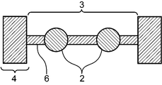
- the stretchable circuit board of the present embodiment includes a stretchable insulating layer 1 and wiring 3 as shown in FIG. 1 as an example.
- the wiring 3 is composed of a combination of a metal wiring portion 6 constituting the main portion thereof and a conductive expansion / contraction portion 2 incidentally arranged on the metal wiring portion 6.
- a part of the wiring 3 is made of a conductive elastic material and is made of the conductive elastic part 2, or a part of the wiring 3 is reinforced by the conductive elastic part 2. It is characterized by being, or both.
- the maximum region and the minimum region of the amplitude of the wavy wiring are composed of the conductive expansion / contraction portion 2, and as shown at both ends, a part of the pad portion 4 is the wavy conductive portion. It is composed of a stretchable portion 2.
- the shape of the wiring 3 is not limited to the wave shape, and for example, there may be a crosslinked portion composed of the conductive expansion / contraction portion 2 in the linear wiring 3 as shown in FIG. Alternatively, it may be a meander wiring as shown in FIG. 3, or a crosslinked portion in which the maximum region and the minimum region of the amplitude of the meander wiring are composed of the conductive expansion / contraction portion 2.
- a crosslinked portion composed of the conductive stretchable portion 2 at a portion on the wiring where breakage is likely to occur, that is, a portion vulnerable to elongation.
- the structure of the circuit board itself is stretched by the time the conductive composition is stretched, and the stretch of the structure itself is stretched, as compared with the case where the wiring is straight or the conductive stretchable portion is not provided.
- the conductive composition begins to grow only when it is finished. Therefore, there is an advantage that an increase in resistance with respect to the elongation rate is suppressed.
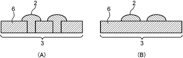
- the metal wiring portion 6 is broken and the conductive expansion / contraction portion 2 fills the space between the metal wiring portions 6, but this is because a part of the wiring 3 is the conductive portion.
- the form composed of the expansion / contraction part 2 is shown.
- the circuit board of the present embodiment is not limited to the above embodiment, and for example, as shown in FIG. 7B, the metal wiring portion 6 is not broken, and the conductive expansion / contraction portion 2 is a part of the wiring 3. It may be formed on the surface so as to reinforce. Further, as shown in FIG. 7A, when the metal wiring portion 6 is broken, even if the conductive expansion / contraction portion 2 is wider than the disconnection width on the surface of the metal wiring portion 6. It doesn't have to be widespread.
- FIG. 8 is a view of the wiring 3 from the back, but in FIG. 8, the metal wiring portion 6 is not broken, and the conductive expansion / contraction portion 2 is formed on the surface so as to reinforce a part of the wiring 3. It is a plan view when it is done. For example, it is shown that a part of the metal wiring portion 6 is narrowly constricted as shown in FIG. 8, and at least a part of the constricted portion is crosslinked by the conductive expansion / contraction portion 2. As a result, breakage (disappearance of continuity) on the wiring is suppressed with respect to in-plane bending of the stretchable circuit board.
- the stretchable circuit board in one embodiment may further include a pad portion 4 composed of a metal layer 5 constituting a main portion, as shown in FIG. ..
- the stretchable circuit board includes the wiring 3 (right side) and the pad portion 4 (left side). Since breakage (and poor conduction due to this) often occurs at the connection portion between the pad portion 4 and the metal wiring portion 6 constituting the wiring 3, as shown in FIG. 4, the metal wiring portion 6 and the metal wiring portion 6 are described.
- the connection portion with the pad portion 4 is composed of the conductive expansion / contraction portion 2, the connection portion is reinforced by the conductive expansion / contraction portion 2, or both.
- the connection portion between the wiring 3 and the pad portion 4 is composed of the conductive expansion / contraction portion 2 incidentally arranged on the connection portion.
- the pad portion 4 composed of the metal layer 5
- the metal layer may be damaged such as cracks or cracks during expansion and contraction. Therefore, as shown in FIG. 5 (enlarged view of the pad portion 4), whether a part of the metal layer 5 constituting the pad portion 4 is composed of the conductive stretchable portion 2 or the pad portion 4 is formed.
- a part of the constituent metal layer 5 may be reinforced by the conductive stretchable portion 2, or both of them.
- the pad portion 4 is composed of the metal layer 5 constituting the main portion thereof and the conductive stretchable portion 2 incidentally arranged on the metal layer 5.
- the wiring 3 and the pad portion 4 may be provided not only on one side of the stretchable insulating layer 1 but also on both sides.
- the wiring 3 or the pad portion 4 formed on one side of the elastic insulating layer 1 and the wiring 3 or the pad portion 4 formed on the other surface are conductive. It may be cross-linked by the stretchable portion 2.
- the conductive expansion / contraction portion 2 does not necessarily have to penetrate the wiring 3, and for example, as shown in FIG. 6, it penetrates through the wiring 3 or the pad portion 4 on one side and the wiring 3 or the pad portion on the opposite side. In 4, it may be configured that it does not penetrate.
- each configuration (stretchable insulating layer, metal wiring portion, metal layer, conductive stretchable portion) of the stretchable circuit board of the present embodiment is not particularly limited, but for example, a material as described below is used. It is possible.
- the stretchable insulating layer in the present embodiment is not particularly limited as long as it is a stretchable insulating layer.
- the insulating layer in the present embodiment may or may not be transparent, but more preferably it has a transparency of 70% or more in total light transmittance.
- a resin composition or an epoxy resin composition containing polyrotaxane as described later is used as a constituent material of the insulating layer, the transparency can be obtained by selecting an epoxy resin or a curing agent thereof.
- the thickness of the insulating layer is not particularly limited, but for example, a thickness of 10 ⁇ m to 200 ⁇ m is preferable from the viewpoint of handleability, optical characteristics, and wearability.
- the insulating layer provided in the circuit board of the present embodiment is preferably an insulating layer that is elastically deformable, has little residual strain, and has stress relaxation property.
- the cured product is an insulating layer made of a resin composition that is elastically deformable, has little residual strain, and has stress relaxation properties.
- elastic deformation and low residual strain means that there is no plastic deformation and the residual strain is preferably 3% or less.
- having stress relaxation property means having a property of reducing the applied stress so that the residual stress becomes small when a force (for example, tensile force) is applied.
- the residual strain and stress relaxation property of the resin composition are defined by the stress relaxation rate R and the residual strain rate ⁇ measured by the extension-restoration test described later.
- the resin composition of the present embodiment is a resin composition in which the stress relaxation rate R is 20 to 95% and the residual strain rate ⁇ is 0 to 3% in the cured product. More preferably, the resin composition has a stress relaxation rate R of 30 to 60% and a residual strain ⁇ of 0 to 1.5%.
- An insulating layer using a resin composition exhibiting a stress relaxation rate and a residual strain rate in such a range is said to have elasticity, high stress relaxation property during tension, and excellent restoration property after stretching. It is considered to have excellent reliability because it has both characteristics and is not easily destroyed.
- extension-restoration test In the extension-restoration test used in this embodiment, ISO3384 is used with a cured product piece of the resin composition (thickness: 50 ⁇ m, sample shape: dumbbell No. 6 (measurement site width: 4 mm, parallel portion length: 25 mm)). Using a tensile-compression tester (for example, an autograph (model: AGS-X) manufactured by Shimadzu Corporation) that complies with the above, the extension stroke is performed under the following conditions, and then the restoration stroke is performed. The stress relaxation rate is calculated by the following calculation method. R and the residual strain rate ⁇ are calculated.
- a tensile-compression tester for example, an autograph (model: AGS-X) manufactured by Shimadzu Corporation
- Extension stroke condition In order to remove the deflection generated when the test piece is attached to the gripping tool, the deflection correction is performed with a force of 0.05 N or less.
- Test speed 25 mm / min, from 0 to 25% elongation Temperature condition: 23 ° C Stretching / holding conditions: 25% stretching, holding time 5 minutes
- the stress relaxation rate calculation method The tensile force at the end of the stretching stroke is measured, and this is taken as the initial tensile force F A0 . Then, the strain amount is held under the above-mentioned stretching / holding conditions, and the tensile force is measured after 5 minutes. This is referred to as F A (t 5).
- the stress relaxation rate R is calculated by the following formula.
- Residual strain rate calculation method In the restoration stroke, when the tensile force becomes 0 ⁇ 0.05 N, the strain amount is measured and this is defined as the residual strain ⁇ .
- the resin composition has the maximum stress value measured at the maximum extension (at 25% extension) in the extension-restoration test. As a result, the yield phenomenon of the material does not occur, and it becomes possible to develop higher resilience.
- the resin composition of the present embodiment is preferably a resin composition that satisfies each of the above relationships even if the stretching stroke and the restoring stroke are repeated two or more times in the stretching-restoration test. As a result, it is possible to obtain a resin composition which is more excellent in resilience and does not lose its resilience even when stretched a plurality of times. Such a resin composition is considered to be further excellent in bending resistance and the like in, for example, a flexible display device.
- the resin composition of the present embodiment has a tensile force FB 0 immediately after the end of the extension stroke and 30 minutes have passed after the end of the extension stroke.
- tensile force F B at the time of the (t 30) the following formula: 0.1 ⁇ (F B (t 30 ) / F B0) ⁇ 0.7 It is desirable that the resin composition satisfies the above conditions.
- Stress relaxation test Using a cured piece of resin composition (thickness: 50 ⁇ m, sample shape: dumbbell No. 6 (measurement site width: 4 mm, parallel part length: 25 mm)), a tensile-compression tester compliant with ISO3384 under the following conditions. Perform the stretching stroke with, measure the tensile force at the end of stretching, and let this be the initial tensile force F B 0 . Then, to measure the tensile force F B after 30 minutes (t 30).
- Deflection correction is performed to remove the deflection that occurs when the test piece is attached to the grip. Deflection correction is performed with a force of 0.05 N or less. Test speed: 25 mm / min, up to 50% elongation Temperature condition: 23 ° C Stretching / holding conditions: 50% stretch, holding time 30 minutes
- the resin composition used in the present embodiment can be restored to its original state under arbitrary conditions even if stretching and holding are repeated two or more times (that is, after the first test is completed). It is preferable that each of the above relationships is satisfied (even if the sample is repeatedly measured).
- the resin composition used for the insulating layer of the present embodiment is not particularly limited as long as it has the above-mentioned characteristics.
- the resin composition of the present embodiment contains at least a thermosetting resin and a curing agent thereof.
- a thermosetting resin an epoxy resin is preferably exemplified.
- a resin composition containing polyrotaxane (A), a thermosetting resin (B) and a curing agent (C) can be mentioned.
- A polyrotaxane
- B thermosetting resin
- C curing agent
- polyrotaxane (A) examples include polyrotaxane as described in Japanese Patent No. 4482633 or International Publication No. WO2015 / 052853 pamphlet.
- Commercially available products may be used, and specifically, Serum Superpolymer A1000 manufactured by Advanced Soft Materials Co., Ltd. can be used.
- thermosetting resin (B) examples include thermosetting resins such as epoxy resin, phenol resin, polyimide resin, urea resin, melamine resin, unsaturated polyester, and urethane resin without particular limitation. Of these, it is preferable to use an epoxy resin.
- the epoxy resin examples include bisphenol A type epoxy resin, bisphenol F type epoxy resin, bisphenol S type epoxy resin, aralkyl epoxy resin, phenol novolac type epoxy resin, alkylphenol novolac type epoxy resin, and biphenol type epoxy.
- examples thereof include resins, naphthalene-type epoxy resins, dicyclopentadiene-type epoxy resins, epoxidized products of condensates of phenols and aromatic aldehydes having phenolic hydroxyl groups, triglycidyl isocyanurate, alicyclic epoxy resins and the like. These may be used individually by 1 type or in combination of 2 or more type depending on the situation.
- an epoxy resin containing two or more epoxy groups in one molecule and having a molecular weight of 500 or more is preferably exemplified.
- an epoxy resin a commercially available epoxy resin may be used, for example, JER1003 (manufactured by Mitsubishi Chemical Co., Ltd., molecular weight 1300, bifunctional), EXA-4816 (manufactured by DIC, molecular weight 824, bifunctional), YP50 (Nippon Steel). Sumitomo Metals Chemical Co., Ltd., molecular weight 60,000 to 80,000, bifunctional) and the like.
- the epoxy resin has an alkylene oxide-modified modifying group having 2 to 3 carbon atoms and the modifying group is contained in 1 mol molecule of the epoxy in an amount of 4 mol or more, and has an epoxy group of 2 mol or more.
- the thermosetting resin (B) and the curing agent (C) which are epoxy resins having an epoxy equivalent of 450 eq / mol or more, the cured product is a resin having the extensibility and the tensile elasticity. It is possible to obtain a composition.
- epoxy resin examples include propylene oxide-added bisphenol A type epoxy resin (ADEKA EP4003S), ethylene oxide-added hydroxyphenylfluorene type epoxy resin (Osaka Gas Chemicals EG-280), and the like. Be done.
- a resin composition containing a single component of polyrotaxane (A) and a thermosetting resin (B) and a curing agent (C) may be used, but both components ((A) and (B)) may be used. It is preferable to prepare a resin composition containing the curing agent (C) because the cured product can easily obtain the resin composition having the extensibility and the tensile elastic modulus. Further, one type of epoxy resin as described above may be used alone, or two or more types may be used in combination.
- the curing agent (C) is not particularly limited as long as it works as a curing agent for the thermosetting resin (B).
- examples of the epoxy resin that can be preferably used as a curing agent include phenol resins, amine compounds, acid anhydrides, imidazole compounds, sulfide resins, and dicyandiamides.
- a light / ultraviolet curing agent, a thermal cation curing agent, and the like can also be used. Depending on the situation, one of these may be used alone, or two or more thereof may be used in combination.
- the resin composition may contain a curing accelerator, if necessary. Examples of the effect promoter include imidazole compounds and the like.
- a cross-linking agent may be further added, and such a cross-linking agent is at least a part of the cyclic molecule of the polyrotaxane. It can be used without particular limitation as long as it can form a structure that crosslinks with (at least one reactive group of the cyclic molecule of polyrotaxane). Specific examples thereof include isocyanate and cyanuric chloride.
- the ratio of each component in the resin composition is not particularly limited as long as the effects of the present invention can be exhibited, but for example, when all the components (A), (B) and (C) are contained, the above.
- the polyrotaxane (A) is about 10 to 80 parts by mass, more preferably about 30 to 50 parts by mass;
- the thermosetting resin (B) is 10 to 89.9 parts by mass.
- the curing agent (C) is about 0.1 to 30 parts by mass, more preferably about 0.1 to 20 parts by mass.
- the resin composition of the present embodiment contains an isocyanate resin as a cross-linking agent
- 0 to 50 parts by mass of the isocyanate resin can be added to the polyrotaxane (A), and further, 10 to 40 parts by mass. It is preferable to add it.
- the component (B) and the component (C) are contained and the component (A) is not contained, the total amount of the resin composition is 100 parts by mass, and the thermosetting resin (B) is 50 to 99 parts by mass, more preferably. About 60 to 80 parts by mass;
- the curing agent (C) is about 1 to 50 parts by mass, more preferably about 1 to 40 parts by mass.
- the resin composition according to the present embodiment contains other additives such as a curing catalyst (curing accelerator), a flame retardant, a flame retardant aid, a leveling agent, and a colorant as long as the effects of the present invention are not impaired. Etc. may be contained as needed.
- the method for preparing the resin composition of the present embodiment is not particularly limited. For example, first, an epoxy resin, a curing agent, a cross-linking agent, a thermosetting resin and a solvent are mixed so as to be uniform, and the resin of the present embodiment is prepared. The composition can be obtained.
- the solvent used is not particularly limited, and for example, toluene, xylene, methyl ethyl ketone, acetone and the like can be used. These solvents may be used alone or in combination of two or more. Further, if necessary, an organic solvent for adjusting the viscosity and various additives may be blended.
- the solvent can be cured while evaporating to obtain an insulating layer.
- the method, apparatus, and conditions for heating and drying the resin composition may be various means similar to the conventional ones, or improved means thereof.
- the specific heating temperature and time can be appropriately set depending on the cross-linking agent and solvent used, and for example, the resin composition is cured by heating and drying at 50 to 200 ° C. for about 60 to 180 minutes. be able to.
- the insulating layer thus obtained (molded product which is a cured product of the resin composition or the like) may be surface-treated in order to stably form wiring (conductive layer) on one surface thereof. .. Further, various additives such as antioxidants, weather stabilizers, flame retardants, antistatic agents and the like can be added as long as their characteristics are not impaired.
- the metal wiring portion and the metal layer may use various metal foils, metal inks, spatters, and the like used for forming wiring and pad portions of general circuit boards without particular limitation. it can.
- the metal foil is not particularly limited, and examples thereof include copper foil (plating) and aluminum foil, and these metal foils may be metal foils surface-treated with a silane coupling agent or the like.
- a wiring or a pad portion using such a metal foil
- one or a plurality of the above-mentioned elastic insulating layers are laminated, and further, a metal foil such as a copper foil is laminated on both upper and lower surfaces or one side thereof.
- a metal foil such as a copper foil
- a conductor layer (wiring, pad, etc.) can be provided as a circuit on the surface of the elastic insulating layer of the present embodiment.
- examples of the method for forming a circuit include a semi-additive method (SAP: Semi Adaptive Process) and a modified semi-additive method (MSAP: Modified Semi Adaptive Process).
- the conductive stretchable portion of the present embodiment can be used without particular limitation as long as it is a member having both conductivity and stretchability, but may be formed of, for example, a conductive composition having stretchability, for example, curing.
- a conductive paste using a resin composition having elasticity as a binder can be used.
- a liquid metal can be used for the conductive stretchable portion.
- the conductive stretchable portion of the present embodiment is further characterized in that the Tg or softening point is 40 ° C. or lower, or the elastic modulus at 30 ° C. is less than 1.0 GPa.
- the Tg or softening point of the conductive stretchable portion exceeds 40 ° C., the elastic modulus near room temperature increases, so that the flexibility at room temperature decreases.
- the lower limit of Tg or the softening point is not particularly limited, and the lower the Tg or the softening point, the better the flexibility and elasticity at room temperature.
- the Tg or softening point of the conductive stretchable portion is preferably ⁇ 40 ° C. or higher, more preferably ⁇ It is 30 ° C. or higher.
- the elastic modulus at 30 ° C. is 1.0 GPa or more, the internal stress during expansion and contraction or deformation becomes high, and when a conductive composition is used for the conductive expansion / contraction portion, the conductive filler is broken or conductive. Destruction at the interface between the filler and the resin is likely to be induced, which may cause a decrease in conductivity during expansion and contraction.
- the lower limit of the elastic modulus at 30 ° C. is not particularly limited, but from the viewpoint of shape resilience, it is preferably 100 kPa or more, and more preferably 500 kPa or more.
- the conductive composition contains a resin (D) serving as a stretchable binder, a curing agent (E) that reacts with the resin (D), and a conductive filler (F), and the resin.
- (D) has a functional group having a functional group equivalent of 400 g / eq or more and 10000 g / eq or less, and the cured product of the resin (D) and the conductive composition has a glass transition temperature (Tg).
- Tg glass transition temperature
- the softening point is 40 ° C or less, or the elastic conductivity at 30 ° C is less than 1.0 GPa
- the conductive filler (F) has an intrinsic volume resistivity at room temperature of 1 ⁇ 10 -4 ⁇ .
- Examples thereof include a resin composition composed of a conductive substance having a size of cm or less.
- Examples of the functional group include an epoxy group, a vinyl group, a (meth) acryloyl group, a hydroxyl group, a carboxyl group, an amino group, an alkoxy group, and a carbonyl group.
- the component of the molecular structure of the resin (D) may be a single component, or a plurality of types may be used in combination at an arbitrary ratio. It is preferable that the molecular structure of the resin (D) is a molecular structure containing at least one selected from (meth) acrylic acid ester, styrene, and nitrile as a component. As specific examples, epoxy-modified (meth) acrylic acid ester, hydroxyl group-modified (meth) acrylic acid ester, carboxyl group-modified (meth) acrylic acid ester and the like are preferably exemplified.
- the resin (D) preferably has a weight average molecular weight of 50,000 or more.
- the upper limit of the weight average molecular weight is not particularly limited, but when the molecular weight exceeds 3 million, the viscosity may increase and the handleability may decrease, which is preferable as the weight average molecular weight range of the resin (D). Is 50,000 or more and 3 million or less, more preferably 100,000 or more and 1 million or less.
- curing agent (E) various curing agents can be used without particular limitation as long as they have reactivity with the resin (D) as described above.
- specific examples of the curing agent (E) include radical generators such as imidazole compounds, amine compounds, phenol compounds, acid anhydride compounds, isocyanate compounds, mercapto compounds, onium salts, and peroxides, and light. Examples include acid generators.
- the conductive filler (F) is made of a conductive substance having an intrinsic volume resistivity of 1 ⁇ 10 -4 ⁇ ⁇ cm or less at room temperature.
- the volume resistivity of the conductive composition is approximately 1 ⁇ 10 -3 ⁇ ⁇ , although it depends on the blending amount. It is cm to 1 x 10 -2 ⁇ ⁇ cm. Therefore, in the case of a circuit, the resistance value becomes high and the power loss becomes large.
- Examples of the conductive substance include simple substances composed of metal elements such as silver, copper, and gold, and oxidation containing these elements. Examples include compounds such as substances, nitrides, carbides and alloys.
- a conductive or semi-conductive conductive auxiliary agent may be added to the conductive composition for the purpose of further improving the conductivity.
- a conductive or semi-conductive auxiliary agent a conductive polymer, an ionic liquid, carbon black, acetylene black, carbon nanotubes, an inorganic compound used as an antistatic agent, or the like can be used, and only one kind can be used. It may be used or two or more types may be used at the same time.
- the conductive filler (F) preferably has a flat shape, and preferably has a thickness and an aspect ratio in the in-plane longitudinal direction of 10 or more.
- the aspect ratio is 10 or more, not only the surface area of the conductive filler with respect to the mass ratio becomes large and the efficiency of conductivity increases, but also the adhesion with the resin component is improved and the elasticity is improved. ..
- the aspect ratio is 1000 or less, it is preferably 10 or more and 1000 or less, and more preferably 20 or more and 500 or less, from the viewpoint of ensuring better conductivity and printability.
- Examples of the conductive filler having such an aspect ratio include a conductive filler having a tap density of 6.0 g / cm 3 or less measured by the tap method. Further, when the tap density is 2.0 g / cm 3 or less, the aspect ratio becomes larger, which is more preferable.
- the blending ratio of the conductive filler (F) in the conductive composition is 40 to 95% by mass in terms of mass ratio. It is preferable in terms of conductivity, cost, and printability, and more preferably 60 to 85% by mass.
- the particle size of the conductive filler (F) of the present embodiment is not particularly limited, but average particles measured by a laser light scattering method from the viewpoint of printability during screen printing and appropriate viscosity in kneading of the formulation.
- the diameter (particle size at a cumulative volume of 50%; D50) is preferably 0.5 ⁇ m or more and 30 ⁇ m or less, and more preferably 1.5 ⁇ m or more and 20 ⁇ m or less.
- the conductive filler (F) is preferably a conductive filler whose surface is coupled.
- the resin composition of the present embodiment may contain a coupling agent.
- the coupling agent to be added to the conductive composition or for coupling the conductive filler can be used without particular limitation as long as it is adsorbed on the filler surface or reacts with the filler surface.
- Examples thereof include silane coupling agents, titanate-based coupling agents, and aluminum-based coupling agents.
- the amount of the coupling agent added is preferably about 1% by mass to 20% by mass with respect to the entire conductive composition.
- the ratio of each component in the conductive composition is not particularly limited as long as the effect of the present invention can be exhibited, and the compounding ratio of the (F) resin: the (G) curing agent is the resin and the curing. Depending on the type of agent, it can be appropriately determined in consideration of the equivalent ratio and the like.
- additives and the like can be added to the conductive composition depending on the purpose.
- additives include elastomers, surfactants, dispersants, colorants, fragrances, plasticizers, pH adjusters, viscosity regulators, ultraviolet absorbers, antioxidants, lubricants and the like.
- the method for preparing the conductive composition is not particularly limited as long as the conductive composition can be produced.
- a method for preparing the conductive composition for example, the above-mentioned resin component, the conductive filler, a curing agent, a dispersant and the like, if necessary, and a solvent are mixed and stirred so as to be uniform, and the above-mentioned Examples thereof include a method for obtaining a conductive composition.
- the mixing / stirring method is not particularly limited, and a high-shear dispersion device such as a rotation-revolution mixer or a three-roll mill is preferably used. Further, vacuum defoaming may be performed.
- liquid metal of the present embodiment for example, an alloy of gallium, indium, tin, which is liquid at room temperature, or the like is used.
- An inorganic filler or the like may be added to the liquid metal for adjusting the viscosity from the viewpoint of maintaining the shape.
- a conductive stretchable portion bridged portion
- the conductive composition or liquid metal of the present embodiment is applied onto the stretchable insulating layer, metal wiring portion or metal layer as described above.
- a coating film of the conductive composition can be formed by coating or printing on the surface, and a conductive stretchable portion (crosslinked portion) can be formed at a desired portion.
- a crosslinked portion or the like can be formed on the stretchable insulating layer, the metal wiring portion, or the metal layer by the following steps. That is, first, a coating film is formed by applying or printing the conductive composition or liquid metal of the present embodiment on the stretchable insulating layer, the metal wiring portion or the metal layer, and volatilization contained in the coating film by drying. Remove the ingredients. The resin (D) and the curing agent (F) are cured by the subsequent curing steps such as heating, electron beam, and light irradiation, and the coupling agent and the conductive filler (F) are combined with the resin (D).
- a conductive stretchable portion (crosslinked portion) can be formed by a step of reacting the curing agent (F) with the curing agent (F).
- Each condition in the curing step and the reaction step is not particularly limited, and may be appropriately set depending on the type of resin, curing agent, filler, etc. and the desired form.
- the step of applying the conductive composition of the present embodiment is not particularly limited, and for example, a coating method such as an applicator, a wire bar, a comma roll, or a gravure roll, a screen, a flat plate offset, a flexo, an inkjet, a stamping, a dispense, or a squeegee.
- a coating method such as an applicator, a wire bar, a comma roll, or a gravure roll, a screen, a flat plate offset, a flexo, an inkjet, a stamping, a dispense, or a squeegee.
- a printing method using the above can be used.
- the conductive stretchable portion may be formed inside the insulating layer as described above.
- a hole is made with a drill or a laser, and the hole is made conductive. It can contain compositions and liquid metals.
- the passage that penetrates from the outer surface of the copper on the double-sided plate to the outer surface of the copper on the opposite side may be filled with the conductive composition, or the conductive composition may be filled from the outer surface of the copper to the inner surface of the copper on the opposite side. You may. By doing so, the conductive stretchable portion can be formed inside the insulating layer.
- the stretchable circuit board of the present embodiment is particularly flexible, has excellent stress relaxation and resilience, and has elasticity and flexibility. Therefore, for example, a bendable electronic paper, an organic EL display, a solar cell, and an RFID. , Very suitable as an electronic material used for pressure sensors and the like.
- the stretchable circuit board of the present embodiment is extremely useful for industrial use because it can suppress breakage of wiring caused by expansion and contraction, increase in conductive resistance due to expansion and contraction, and occurrence of poor conductivity.
- the elastic circuit board of the present invention has a wide range of industrial applicability in technical fields such as wearable devices, patch devices, flexible display devices, optical fields, electronic fields, adhesive fields, and medical fields.
Landscapes
- Engineering & Computer Science (AREA)
- Microelectronics & Electronic Packaging (AREA)
- Structure Of Printed Boards (AREA)
- Parts Printed On Printed Circuit Boards (AREA)
- Printing Elements For Providing Electric Connections Between Printed Circuits (AREA)
Priority Applications (3)
| Application Number | Priority Date | Filing Date | Title |
|---|---|---|---|
| US17/440,453 US12207397B2 (en) | 2019-03-27 | 2020-03-26 | Stretchable circuit board |
| JP2021509582A JP7426592B2 (ja) | 2019-03-27 | 2020-03-26 | 伸縮性回路基板 |
| CN202080020114.6A CN113545173B (zh) | 2019-03-27 | 2020-03-26 | 伸缩性电路基板 |
Applications Claiming Priority (2)
| Application Number | Priority Date | Filing Date | Title |
|---|---|---|---|
| JP2019061651 | 2019-03-27 | ||
| JP2019-061651 | 2019-03-27 |
Publications (1)
| Publication Number | Publication Date |
|---|---|
| WO2020196745A1 true WO2020196745A1 (ja) | 2020-10-01 |
Family
ID=72612044
Family Applications (1)
| Application Number | Title | Priority Date | Filing Date |
|---|---|---|---|
| PCT/JP2020/013644 Ceased WO2020196745A1 (ja) | 2019-03-27 | 2020-03-26 | 伸縮性回路基板 |
Country Status (4)
| Country | Link |
|---|---|
| US (1) | US12207397B2 (https=) |
| JP (1) | JP7426592B2 (https=) |
| CN (1) | CN113545173B (https=) |
| WO (1) | WO2020196745A1 (https=) |
Cited By (4)
| Publication number | Priority date | Publication date | Assignee | Title |
|---|---|---|---|---|
| CN115776757A (zh) * | 2021-09-07 | 2023-03-10 | 鹏鼎控股(深圳)股份有限公司 | 可伸缩电路板 |
| WO2024090348A1 (ja) * | 2022-10-24 | 2024-05-02 | 株式会社村田製作所 | 伸縮性デバイス |
| JP2025517186A (ja) * | 2022-05-09 | 2025-06-03 | マイダス エイチアンドティー インコーポレイテッド | 異方伝導性弾性素材、その製造方法、及びそれを含む弾性電子素子 |
| US12477651B2 (en) | 2021-09-16 | 2025-11-18 | Panasonic Intellectual Property Management Co., Ltd. | Method for manufacturing stretchable circuit board, metal-clad laminated sheet, metal foil with resin, stretchable circuit board, and stretchable circuit mounted article |
Families Citing this family (4)
| Publication number | Priority date | Publication date | Assignee | Title |
|---|---|---|---|---|
| CN110875533B (zh) | 2018-09-04 | 2022-05-31 | 申泰公司 | 超高密度的低矮型边缘卡连接器 |
| WO2022094467A1 (en) * | 2020-11-02 | 2022-05-05 | Samtec, Inc. | Flex circuit and electrical communication assemblies related to same |
| CN116170935A (zh) * | 2021-11-24 | 2023-05-26 | 宏启胜精密电子(秦皇岛)有限公司 | 电路板及其制造方法 |
| US12343150B2 (en) * | 2022-02-25 | 2025-07-01 | Murata Manufacturing Co., Ltd. | Electrode |
Citations (4)
| Publication number | Priority date | Publication date | Assignee | Title |
|---|---|---|---|---|
| US20130256004A1 (en) * | 2012-03-30 | 2013-10-03 | Nokia Corporation | Deformable Apparatus and Method |
| US20140340857A1 (en) * | 2013-05-14 | 2014-11-20 | Mc10, Inc. | Conformal electronics including nested serpentine interconnects |
| JP2017118109A (ja) * | 2015-12-21 | 2017-06-29 | パナソニックIpマネジメント株式会社 | 基板 |
| JP2020088271A (ja) * | 2018-11-29 | 2020-06-04 | 株式会社ジャパンディスプレイ | フレキシブル基板 |
Family Cites Families (18)
| Publication number | Priority date | Publication date | Assignee | Title |
|---|---|---|---|---|
| US7491892B2 (en) | 2003-03-28 | 2009-02-17 | Princeton University | Stretchable and elastic interconnects |
| TWI370714B (en) * | 2008-01-09 | 2012-08-11 | Ind Tech Res Inst | Circuit structure and menufacturing method thereof |
| US8207473B2 (en) * | 2008-06-24 | 2012-06-26 | Imec | Method for manufacturing a stretchable electronic device |
| WO2010086033A1 (en) * | 2009-01-30 | 2010-08-05 | Interuniversitair Microelektronica Centrum Vzw | Stretchable electronic device |
| EP2392196B1 (en) | 2009-01-30 | 2018-08-22 | IMEC vzw | Stretchable electronic device |
| US8329493B2 (en) * | 2009-03-20 | 2012-12-11 | University Of Utah Research Foundation | Stretchable circuit configuration |
| EP2785792B1 (en) | 2011-12-02 | 2015-08-12 | E. I. du Pont de Nemours and Company | Conductive metal composition |
| JP5855979B2 (ja) | 2012-03-07 | 2016-02-09 | 日本メクトロン株式会社 | 伸縮性フレキシブル回路基板 |
| US20140299362A1 (en) | 2013-04-04 | 2014-10-09 | Electronics And Telecommunications Research Institute | Stretchable electric device and manufacturing method thereof |
| JP2015178597A (ja) | 2014-02-28 | 2015-10-08 | 太陽インキ製造株式会社 | 導電性組成物および導電体 |
| JP6331130B2 (ja) * | 2014-03-31 | 2018-05-30 | パナソニックIpマネジメント株式会社 | 伸縮性フレキシブル基板およびその製造方法 |
| TWI684999B (zh) | 2015-01-14 | 2020-02-11 | 日商東洋紡股份有限公司 | 導電性膜 |
| KR102320382B1 (ko) | 2015-01-28 | 2021-11-02 | 삼성디스플레이 주식회사 | 전자 장치 |
| JP2016178121A (ja) | 2015-03-18 | 2016-10-06 | タツタ電線株式会社 | ストレッチャブルケーブルおよびストレッチャブル回路基板 |
| KR102659601B1 (ko) * | 2016-06-28 | 2024-04-22 | 삼성디스플레이 주식회사 | 표시 장치 |
| JP7124711B2 (ja) | 2016-12-26 | 2022-08-24 | 昭和電工マテリアルズ株式会社 | 配線基板及びその製造方法、並びにストレッチャブルデバイス |
| JP6851035B2 (ja) * | 2018-11-09 | 2021-03-31 | パナソニックIpマネジメント株式会社 | 樹脂組成物、並びに、それを用いた樹脂フィルム、樹脂付金属箔、金属張積層板、配線基板及び回路実装品 |
| TWI788740B (zh) * | 2020-12-09 | 2023-01-01 | 財團法人工業技術研究院 | 可拉伸電路和可拉伸電路佈局方法 |
-
2020
- 2020-03-26 WO PCT/JP2020/013644 patent/WO2020196745A1/ja not_active Ceased
- 2020-03-26 US US17/440,453 patent/US12207397B2/en active Active
- 2020-03-26 JP JP2021509582A patent/JP7426592B2/ja active Active
- 2020-03-26 CN CN202080020114.6A patent/CN113545173B/zh active Active
Patent Citations (4)
| Publication number | Priority date | Publication date | Assignee | Title |
|---|---|---|---|---|
| US20130256004A1 (en) * | 2012-03-30 | 2013-10-03 | Nokia Corporation | Deformable Apparatus and Method |
| US20140340857A1 (en) * | 2013-05-14 | 2014-11-20 | Mc10, Inc. | Conformal electronics including nested serpentine interconnects |
| JP2017118109A (ja) * | 2015-12-21 | 2017-06-29 | パナソニックIpマネジメント株式会社 | 基板 |
| JP2020088271A (ja) * | 2018-11-29 | 2020-06-04 | 株式会社ジャパンディスプレイ | フレキシブル基板 |
Cited By (5)
| Publication number | Priority date | Publication date | Assignee | Title |
|---|---|---|---|---|
| CN115776757A (zh) * | 2021-09-07 | 2023-03-10 | 鹏鼎控股(深圳)股份有限公司 | 可伸缩电路板 |
| US12477651B2 (en) | 2021-09-16 | 2025-11-18 | Panasonic Intellectual Property Management Co., Ltd. | Method for manufacturing stretchable circuit board, metal-clad laminated sheet, metal foil with resin, stretchable circuit board, and stretchable circuit mounted article |
| JP2025517186A (ja) * | 2022-05-09 | 2025-06-03 | マイダス エイチアンドティー インコーポレイテッド | 異方伝導性弾性素材、その製造方法、及びそれを含む弾性電子素子 |
| WO2024090348A1 (ja) * | 2022-10-24 | 2024-05-02 | 株式会社村田製作所 | 伸縮性デバイス |
| JPWO2024090348A1 (https=) * | 2022-10-24 | 2024-05-02 |
Also Published As
| Publication number | Publication date |
|---|---|
| CN113545173A (zh) | 2021-10-22 |
| US12207397B2 (en) | 2025-01-21 |
| CN113545173B (zh) | 2024-09-10 |
| US20220167497A1 (en) | 2022-05-26 |
| JPWO2020196745A1 (https=) | 2020-10-01 |
| JP7426592B2 (ja) | 2024-02-02 |
Similar Documents
| Publication | Publication Date | Title |
|---|---|---|
| WO2020196745A1 (ja) | 伸縮性回路基板 | |
| JP7065349B2 (ja) | シート状構造体、フレキシブル表示装置及び樹脂シート | |
| US20110217512A1 (en) | Laminated body and method for producing laminated body | |
| KR102649655B1 (ko) | 접착제 조성물 | |
| JP4893046B2 (ja) | 電子機器用接着剤組成物、それを用いた電子機器用接着剤シート | |
| JP6369788B2 (ja) | エレクトロニクス用構造体 | |
| US20180061519A1 (en) | Conductive resin composition and electronic circuit member using the same | |
| KR100903137B1 (ko) | 열경화성 접착제 필름 및 그것을 사용한 접착 구조물 | |
| KR102906596B1 (ko) | 디바이스용 접착 시트 | |
| JP4374395B1 (ja) | 接着フィルム | |
| CN111886292B (zh) | 导电性组合物以及使用其的导电性结构体 | |
| US7779538B2 (en) | Method for mutually connecting circuit boards | |
| KR20150005473A (ko) | 접착 필름의 전착 방법, 접속 구조체의 제조 방법 | |
| JP2022149589A (ja) | フレキシブルプリント配線板(fpc)用接着剤組成物、並びに該組成物を含む熱硬化性樹脂フィルム、プリプレグ、及びfpc基板 | |
| JP7554982B2 (ja) | 導電性樹脂組成物、並びに、それを用いた回路基板および回路基板の製造方法 | |
| KR20250036728A (ko) | 경화성 수지 조성물, 경화성 필름, 및, 적층 필름 | |
| KR101582492B1 (ko) | 접착제 조성물 및 이를 적용한 커버레이 필름 | |
| US12600815B2 (en) | Stretchable resin composition, and resin sheet material, metal foil with resin, metal-clad laminate, and wiring board each including or obtained using same | |
| JP2018188644A (ja) | エレクトロニクス用構造体 | |
| WO2024210100A1 (ja) | フォルダブルデバイス用回路基板、フォルダブルデバイス、並びにフォルダブルデバイス用フィルム材及び積層板 | |
| JP2006233201A (ja) | 異方性導電接着フィルム | |
| KR20250038205A (ko) | 경화성 수지 조성물, 경화성 필름, 및, 적층 필름 |
Legal Events
| Date | Code | Title | Description |
|---|---|---|---|
| 121 | Ep: the epo has been informed by wipo that ep was designated in this application |
Ref document number: 20777053 Country of ref document: EP Kind code of ref document: A1 |
|
| ENP | Entry into the national phase |
Ref document number: 2021509582 Country of ref document: JP Kind code of ref document: A |
|
| NENP | Non-entry into the national phase |
Ref country code: DE |
|
| 122 | Ep: pct application non-entry in european phase |
Ref document number: 20777053 Country of ref document: EP Kind code of ref document: A1 |