WO2020195116A1 - 活性炭及び浄水カートリッジ - Google Patents
活性炭及び浄水カートリッジ Download PDFInfo
- Publication number
- WO2020195116A1 WO2020195116A1 PCT/JP2020/002961 JP2020002961W WO2020195116A1 WO 2020195116 A1 WO2020195116 A1 WO 2020195116A1 JP 2020002961 W JP2020002961 W JP 2020002961W WO 2020195116 A1 WO2020195116 A1 WO 2020195116A1
- Authority
- WO
- WIPO (PCT)
- Prior art keywords
- activated carbon
- water purification
- purification cartridge
- volume
- pore
- Prior art date
- Legal status (The legal status is an assumption and is not a legal conclusion. Google has not performed a legal analysis and makes no representation as to the accuracy of the status listed.)
- Ceased
Links
Images





Classifications
-
- B—PERFORMING OPERATIONS; TRANSPORTING
- B01—PHYSICAL OR CHEMICAL PROCESSES OR APPARATUS IN GENERAL
- B01J—CHEMICAL OR PHYSICAL PROCESSES, e.g. CATALYSIS OR COLLOID CHEMISTRY; THEIR RELEVANT APPARATUS
- B01J20/00—Solid sorbent compositions or filter aid compositions; Sorbents for chromatography; Processes for preparing, regenerating or reactivating thereof
- B01J20/02—Solid sorbent compositions or filter aid compositions; Sorbents for chromatography; Processes for preparing, regenerating or reactivating thereof comprising inorganic material
- B01J20/20—Solid sorbent compositions or filter aid compositions; Sorbents for chromatography; Processes for preparing, regenerating or reactivating thereof comprising inorganic material comprising free carbon; comprising carbon obtained by carbonising processes
-
- B—PERFORMING OPERATIONS; TRANSPORTING
- B01—PHYSICAL OR CHEMICAL PROCESSES OR APPARATUS IN GENERAL
- B01J—CHEMICAL OR PHYSICAL PROCESSES, e.g. CATALYSIS OR COLLOID CHEMISTRY; THEIR RELEVANT APPARATUS
- B01J20/00—Solid sorbent compositions or filter aid compositions; Sorbents for chromatography; Processes for preparing, regenerating or reactivating thereof
- B01J20/28—Solid sorbent compositions or filter aid compositions; Sorbents for chromatography; Processes for preparing, regenerating or reactivating thereof characterised by their form or physical properties
-
- C—CHEMISTRY; METALLURGY
- C01—INORGANIC CHEMISTRY
- C01B—NON-METALLIC ELEMENTS; COMPOUNDS THEREOF; METALLOIDS OR COMPOUNDS THEREOF NOT COVERED BY SUBCLASS C01C
- C01B32/00—Carbon; Compounds thereof
- C01B32/30—Active carbon
- C01B32/354—After-treatment
-
- C—CHEMISTRY; METALLURGY
- C02—TREATMENT OF WATER, WASTE WATER, SEWAGE, OR SLUDGE
- C02F—TREATMENT OF WATER, WASTE WATER, SEWAGE, OR SLUDGE
- C02F1/00—Treatment of water, waste water, or sewage
- C02F1/28—Treatment of water, waste water, or sewage by sorption
Definitions
- the present invention relates to activated carbon and a water purification cartridge.
- Patent Document 1 discloses activated carbon for adsorbing organic chlorine compounds.
- This activated carbon is a granular carbon molded product formed by carbonizing and activating particles of phenol resin powder, and has a pore volume of 0.20 to 0.80 cc / g with a pore diameter of 100 ⁇ or less and a pore diameter.
- the ratio of the pore volume having a pore diameter of 6 to 8 ⁇ to the pore volume of 100 ⁇ or less is 65 vol% or more.
- Patent Document 1 is insufficient from the viewpoint of removing free chlorine. Specifically, while organic chlorine compounds are mainly removed by the adsorption action of activated carbon, free chlorine is removed by an action different from that of organic chlorine compounds. Therefore, it is sufficient to satisfy the above requirements. The reality is that removal performance cannot be obtained.
- the present invention has been made in view of the above-mentioned conventional circumstances, and an object to be solved is to provide activated carbon having excellent free chlorine removal performance and a water purification cartridge using the same.
- the action of removing free chlorine by activated carbon is mainly classified into two actions: an adsorption action in which free chlorine is adsorbed in pores and an oxidative decomposition action in which free chlorine is oxidatively decomposed by activated carbon.
- the inventors of the present application have focused on the fact that the molecular diameter of hypochlorous acid (HClO), which is free chlorine, is about 0.4 nm, and the relationship between the pore volume of a predetermined pore diameter in activated carbon and the chlorine removal life. Researched on, and came to the present invention.
- Activated carbon for removing free chlorine used in water purification cartridges which has a pore volume of 0.0177 cm 3 / g or more and a pore diameter of 0.679 nm or more and 0.733 nm or less as measured by the BET-DFT method.
- a certain activated carbon By using such activated carbon, it is possible to provide a water purification cartridge having excellent free chlorine removal performance. Further, according to this activated carbon, since the pore volume is 0.0177 cm 3 / g or more, for example, the volume of chlorine in the water purification cartridge is smaller than the volume of the activated carbon molded body of the spout-in type water purification cartridge that is widely used. It is possible to achieve a removal life of 900 L.
- a water purification cartridge comprising an activated carbon molded product containing the activated carbon according to the above [3], wherein the volume of the activated carbon molded product is 37.6 cm 3 or less.
- this water purification cartridge for example, it is possible to achieve a chlorine removal life of 1200 L of the water purification cartridge with a volume smaller than the volume of the activated carbon molded body of the spout-in type water purification cartridge that is widely used.
- the water purification cartridge 20 of this embodiment is attached to the faucet device shown in FIG.
- the faucet device is attached to the top plate 1 of the kitchen cabinet.
- This faucet device includes a faucet main body 10, an operation handle 11, a water discharge head 13, and a water purification cartridge 20.
- the water purification cartridge 20 is mounted inside the water discharge head 13.
- the water discharge head 13 includes a grip portion 13A and a head portion 13B that is detachably provided with respect to the grip portion 13A.
- the water discharge head 13 can replace the water purification cartridge 20 by removing the head portion 13B from the grip portion 13A when the amount of water flowing through the water purification cartridge 20 exceeds the chlorine removal life.
- the water purification cartridge 20 has a cylindrical shape.
- the water purification cartridge 20 includes an activated carbon molded body 21 shown in FIG. 2, a non-woven fabric that covers the activated carbon molded body 21 from the outer peripheral surface side (not shown), and sealing caps (not shown) provided at both ends of the activated carbon molded body 21. , Equipped with.
- the water purification cartridge 20 can purify water by passing water from the outer peripheral surface of the cylindrical activated carbon molded body 21 toward the center.
- the activated carbon molded body 21 includes a cylindrical core 23 and an activated carbon layer 25 arranged on the outer peripheral surface of the core 23.
- the core 23 is not deformed when the activated carbon molded body 21 is molded, and the obtained activated carbon molded body 21 is incorporated into the water purification cartridge 20 and actually used by the user. It is assumed that it will not be deformed.
- Examples of such a core material include a porous ceramic, a porous metal filter, and a hard non-woven fabric.
- the activated carbon layer 25 contains activated carbon.
- the shape of the activated carbon is not particularly limited, but it can be in the form of particles or fibers.
- the activated carbon layer 25 can be further composed of fibril fibers from the viewpoint of shape retention.
- the activated carbon activated carbon obtained from any starting material can be used. Specifically, activated carbon obtained by activating coconut shells, coal, phenolic resin, etc. can be used, but activated carbon produced from starting materials other than those exemplified here can also be used.
- the fibril fiber any fiber can be used as long as it can retain its shape by entwining particulate activated carbon and is bonded to the surface of the core. Examples of such fibril fibers include acrylic fibers, polyethylene fibers, and cellulose fibers.
- the activated carbon When the activated carbon is in the form of particles, it is preferable to use one having a 50% particle diameter (median diameter) of 50 ⁇ m to 130 ⁇ m in the integrated particle size distribution, and more preferably 60 ⁇ m to 90 ⁇ m. In order to adjust the particle size, two or more kinds of particulate activated carbon having different particle size distributions may be mixed.
- the 50% particle size of the particulate activated carbon is 50 ⁇ m or more, the filtration flow rate of the activated carbon molded product can be secured regardless of the pore size of the core, and clogging is less likely to occur. Further, when the 50% particle size of the particulate activated carbon is 130 ⁇ m or less, the activated carbon molded product tends to exhibit sufficient free chlorine removing performance.
- the activated carbon when it is preferable to use one having a fiber diameter of 5 ⁇ m to 30 ⁇ m, and more preferably 10 ⁇ m to 20 ⁇ m.
- the fiber diameter is 5 ⁇ m or more, the filtration flow rate of the activated carbon molded product can be secured regardless of the pore diameter of the core, and clogging is less likely to occur.
- the strength of the activated carbon becomes high and it becomes difficult to break when molding the activated carbon molded product.
- the fiber diameter when the fiber diameter is 30 ⁇ m or less, the activated carbon molded product tends to exhibit sufficient free chlorine removing performance.
- the activated carbon preferably has a specific surface area of 500 m 2 / g to 4000 m 2 / g, and more preferably 1000 m 2 / g to 2000 m 2 / g.
- the specific surface area is 500 m 2 / g or more, the activated carbon molded product tends to exhibit sufficient free chlorine removal performance.
- the specific surface area is 4000 m 2 / g or less, the strength of the activated carbon becomes high and it becomes difficult to break when molding the activated carbon molded product.
- activated carbon, total pore volume is preferred to use those 0.1cm 3 /g ⁇ 5.0cm 3 / g, using those 0.3cm 3 /g ⁇ 1.5cm 3 / g Is more preferable.
- the activated carbon preferably has a true density of 1.6 g / cm 3 or more, and more preferably 1.8 g / cm 3 or more.
- the true density of activated carbon is usually 2.2 g / cm 3 or less.
- the activated carbon preferably has a bulk density of 0.1 g / cm 3 to 2.0 g / cm 3 , and preferably 0.4 g / cm 3 to 1.3 g / cm 3. More preferred.
- the bulk density is 0.1 g / cm 3 or more, the strength of the activated carbon becomes high and it becomes difficult to break when molding the activated carbon molded product.
- the bulk density is 5.0 g / cm 3 or less, the activated carbon molded product tends to exhibit sufficient free chlorine removal performance.
- the activated carbon of the present embodiment has a pore volume of 0.679 nm or more and 0.733 nm or less (“pore diameter 0.7 nm”, as measured by the BET (Brunauer-Emmett-Teller) -DFT method (Density Functional Theory).
- pore volume is 0.0102 cm 3 / g or more.
- the pore volume, in terms of free chlorine removal property, is preferably 0.0177cm 3 / g or more, more preferably 0.0647cm 3 / g or more, is 0.1967cm 3 / g or more Is even more preferable.
- the pore volume of the activated carbon having a pore diameter of 0.7 nm is preferably 5.0 cm 3 / g or less, preferably 1.5 cm 3 / g or less, from the viewpoint of ensuring sufficient strength to withstand water flow. Is more preferable.
- the pore volume of 1.5 cm 3 / g corresponds to a specific surface area of 4000 m 2 / g.
- the pore volume having a pore diameter of 0.7 nm can be appropriately designed depending on the starting material of the activated carbon, the activation method, the presence or absence of post-treatment after activation, the type of post-treatment, and the like.
- the volume of the activated carbon molded body of the spout-in type water purification cartridge which is widely is approximately 45cm 3.
- the pore volume with a pore diameter of 0.7 nm is 0.0177 cm 3 / g or more, it is possible to achieve a chlorine removal life of 900 L at about 40 cm 3 smaller than a general-purpose product.
- the chlorine removal life of 900 L is equivalent to 3 months, assuming that 10 L of purified water is used a day.
- the pore volume of the pore diameter of 0.7 nm is 0.0475 cm 3 / g or more, it is possible to achieve a chlorine removal life of 900 L with a smaller pore volume of about 37.6 cm 3 .
- the pore volume with a pore diameter of 0.7 nm is 0.1967 cm 3 / g or more, it is possible to achieve a chlorine removal life of 1200 L at about 31.8 cm 3 which is smaller than a general-purpose product, for example.
- the length dimension of the conventional water purification cartridge (diameter of about 2.66 cm) can be reduced to about 2.28 cm while maintaining the same length. This is a size that can be directly incorporated into a pipe with a nominal diameter of 25, which greatly enhances the design of the faucet.
- the chlorine removal life of 1200 L is equivalent to 4 months, assuming that 10 L of purified water is used a day.
- the nominal diameter 25 is shown in JIS B2061 that defines a water tap and JIS G3448 that defines a stainless steel pipe for general piping.
- the shape of the pores formed in the activated carbon was assumed to be slit-shaped.
- the cumulative volume of nitrogen gas adsorbed on the activated carbon during the measurement is measured, and the pore volume (cm 3 / g) at a predetermined pore diameter per 1 g of activated carbon is calculated using analysis software (ASAP2020 analysis program). did.
- the pore volume X (cm 3 / g) having a pore diameter of 0.679 nm or more and 0.733 nm or less per 1 g of activated carbon has a pore volume B (cm 3 / g) having a pore diameter of 0.679 nm or less and a pore diameter of 0.643 nm.
- the difference value from the following pore volume A (cm 3 / g), the pore volume C (cm 3 / g) having a pore diameter of 0.733 nm or less, and the pore volume B (cm 3 ) having a pore diameter of 0.679 nm or less. It was obtained as the total value of the difference values with / g) (X CA).
- the chlorine removal life is measured in accordance with JIS S3201, and the free chlorine removal rate is 80 when free chlorine-containing water with a concentration of 2 ppm is continuously passed under the water flow condition of a filtration flow rate of 2.5 L / min. It was calculated as the cumulative amount of water flow until it decreased to%.
- the reason why the pores having a pore diameter of 0.679 nm or more and 0.733 nm or less are effective for the chlorine removing action is not clear, but it is presumed as follows.
- the radius distribution (RDF) of the distance (r) from the center of the hypochlorite ion to the center of oxygen of the water molecule is calculated by calculating the hydration structure by the first-principles molecular dynamics method. As shown in the graph, it was shown to have a peak near the solvation ion radius of about 3.2 ⁇ (0.32 nm).
- the hydrophilic hypochlorite ion M1 forms a hydrated structure having a diameter of about 0.64 nm in water together with water molecules M2 (see FIGS. 5A, 5B and 5C). ).
- the hypochlorite ion M1 forming this hydrated structure does not easily enter the inside of the pores 25A having a pore diameter of less than 0.679 nm, and is formed by the pores 25A having a pore diameter of less than 0.679 nm.
- the action of removing free chlorine is considered to be small.
- FIG. 5A the hypochlorite ion M1 forms a hydrated structure having a diameter of about 0.64 nm in water together with water molecules M2 (see FIGS. 5A, 5B and 5C).
- the hypochlorite ion M1 forming this hydrated structure may be allowed to enter the inside of the pore 25C having a pore diameter of more than 0.733 nm.
- the pore size 25C is too large for the hypochlorite ion M1 forming the hydrated structure, the distance between the inner wall of the pore 25C and the hypochlorite ion M1 that has entered the inside becomes large. , It is considered that the adsorption and oxidative decomposition of free chlorine by activated carbon are not sufficiently promoted.
- the pore 25C having a pore diameter of more than 0.733 nm has a hydration structure. It is presumed that the hypochlorite ion M1 cannot be sufficiently captured.
- the pores 25B having a pore diameter of 0.679 nm or more and 0.733 nm or less supplement the hypochlorite ion M1 having a preferably hydrated structure as shown in FIG. 5B, and adsorb and oxidatively decompose free chlorine. Is considered to be promoted.
- an activated carbon molded body 21 containing activated carbon having a pore diameter of 0.7 nm and a pore volume of 0.1967 cm 3 / g or more which is measured by the BET-DFT method, which is one aspect of the present embodiment.
- the provided water purification cartridge 20 will be described.
- the volume of the activated carbon molded body 21 of the water purification cartridge 20 is preferably 37.6 cm 3 or less.
- the lower limit of the volume of the activated carbon molded body 21 is not particularly specified, but can be 31.8 cm 3 or more.
- the water purification cartridge 20 has a free chlorine removal rate when continuously passing free chlorine-containing water having a concentration of 2 ppm under a water flow condition of a filtration flow rate of 2.5 L / min, which is measured by a measurement method based on JIS S3201. cumulative through water until reduced to 80%, it is preferable that a volume 1 cm 3 per 37.7L or more activated carbon moldings.
- the water purification cartridge 20 using activated carbon having such a long chlorine removal life can be made smaller than the conventional water purification cartridge while ensuring a sufficient chlorine removal life.
- the volume of the activated carbon molded body 21 and the cumulative water flow rate per unit volume are calculated based on the finding that the chlorine removal life L, which was separately obtained by the inventors of the present application, is proportional to the square of the volume V of the activated carbon molded body. It is a thing. Based on this finding, for activated carbon with a pore diameter of 0.7 nm and different pore volumes, a cartridge with a volume of 37.6 cm 3 of activated carbon was prepared, and a water flow test was conducted in accordance with JIS S3201 to calculate the proportionality constant. , The relational expression between the volume of the activated carbon molded body and the chlorine removal life was derived. The thick solid line graph described as Example 1 in FIG.
- the activated carbon molded product according to the present embodiment will be specifically described with reference to Examples, but the present invention is not limited thereto.
- Activated carbon (1) Specific surface area, total pore volume, pore volume with pore diameter 0.7 nm, pore distribution
- the activated carbons of Examples 1 to 4 have the specific surface area, total pore volume, and pore diameter 0 shown in Table 1. It had a pore volume of 0.7 nm.
- the specific surface area, the total pore volume, and the pore volume having a pore diameter of 0.7 nm were measured as follows. First, 0.1 g of activated carbon is vacuum-heated at 380 ° C., and then nitrogen gas is adsorbed to obtain an adsorption isotherm using a Surface Area Surface Area (ASAP-2020, manufactured by Micromeritics), and the BET method is used.
- SASAP-2020 Surface Area Surface Area
- the specific surface area (m 2 / g) was calculated by Then, the total pore volume (cm 3 / g) of the pores having a pore diameter of 300 nm or less was calculated from this adsorption isotherm.
- the pore volume with a pore diameter of 0.7 nm per 1 g of activated carbon was calculated by the BET-DFT method as described in the above-described embodiment.
- the pore volume of Example 1 having a pore diameter of 0.7 nm was 0.1967 cm 3 / g.
- the pore volume of Example 2 having a pore diameter of 0.7 nm was 0.0177 cm 3 / g.
- the pore volume of Example 3 having a pore diameter of 0.7 nm was 0.0475 cm 3 / g.
- the pore volume of Example 4 having a pore diameter of 0.7 nm was 0.1166 cm 3 / g.
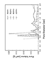
- the pore volume of a predetermined pore diameter was calculated by the BET-DFT method, and the pore distribution was determined. The result is shown in FIG. In the graph of FIG. 6, the horizontal axis represents the pore diameter (nm) and the vertical axis represents the pore volume (cm 3 / g).
- the activated carbons of Examples 1 to 4 had the true density and bulk density shown in Table 1.
- the true density (cm 3 / g) of activated carbon was determined by using 1-butanol as a measuring solution according to the method for measuring the density and specific gravity with a specific gravity bottle of JIS Z 8807.
- a water-permeable non-woven fabric is wrapped around the outer peripheral surface of the obtained activated carbon molded product, and a circular cap capable of completely closing the one end side surface is attached to one end side of the cylindrical activated carbon molded product in the longitudinal direction.
- a water purification cartridge was produced by attaching a circular cap having an open central portion on the other end side.
- Example 4 (2) Preparation of a water purification cartridge using the activated carbon (fibrous) of Example 4
- the activated carbon of Example 4 is wound around a core, and has an outer diameter of 24.5 mm, an inner diameter of 8.3 mm, a length of 90 mm, and a volume.
- a cylindrical activated carbon molded product of 37.6 cm 3 was obtained.
- a water purification cartridge was produced in the same manner as in Examples 1 to 3.
- the weight W of activated carbon was determined as the weight of the entire activated carbon contained in the water purification cartridge (activated carbon molded body).
- the filling rate of activated carbon in the activated carbon molded product is the ratio of the volume of activated carbon (including pores) to the volume V of the activated carbon molded product.
- the volume of the activated carbon including the pores was determined by dividing the weight W of the activated carbon by the bulk density of the activated carbon. The results are shown in Table 2.
- the purification cartridge obtained pore volume of pore diameter 0.7nm in activated carbon molded body, and the pore volume of pore diameter 0.7nm in the activated carbon molded body, pore size 0 per activated carbon molded body 1 cm 3.
- the pore volume of 7 nm was calculated.
- the chlorine removal life is measured by mounting a water purification cartridge on the water purifier built-in faucet "JF-AB461SYX (JW)" manufactured by LIXIL Co., Ltd. and measuring it by a measurement method based on JIS S3201. It was determined as the cumulative amount of water flowed until the free chlorine removal rate decreased to 80% when free chlorine-containing water having a concentration of 2 ppm was continuously passed under the water flow condition of a flow rate of 2.5 L / min. The applied water pressure during water flow was adjusted as shown in Table 2 so as to secure a flow velocity of 2.5 L / min.
- the pressure loss was adjusted by controlling the particle size of the activated carbon in the water purification cartridge and the filling rate of the activated carbon molded product so that the applied water pressure was almost the same.
- the space velocity (SV) during the water flow test is 3989 / h.
- the water flow test was performed on three water purification cartridges in each example, and the average value of the chlorine removal life obtained by the three water flow tests was taken as the chlorine removal life of the water purification cartridge in each example. The results are shown in Table 2.
- Pore distribution of activated carbon of Examples 1 to 4 As shown in the graph of FIG. 6, the activated carbon of Example 1 has a pore distribution peak at 0.733 nm and a pore diameter of 0.679 nm or more and 0.733 nm. The following pore volume was 0.1967 cm 3 / g.
- the water purification cartridge using the activated carbon of Example 1 has a larger pore volume of 0.679 nm or more and 0.733 nm or less than the activated carbon of Examples 2, 3 and 4, and was used for the water purification cartridge. The chlorine removal life of the case was long.
- the activated carbon of Example 4 also had a peak of pore distribution at 0.733 nm, and the chlorine removal life was long when it was used in a water purification cartridge next to the activated carbon of Example 1. From these results, it was suggested that pores having a pore diameter of 0.679 nm or more and 0.733 nm or less are effective for chlorine removal. Further, in the pore distribution, it was shown that the activated carbon having a pore volume peak in the pore diameter of 0.679 nm to 0.733 nm has high chlorine removal performance.
- the activated carbons of Examples 2 and 3 had a peak of pore volume with a pore diameter of less than 0.679 nm, but these activated carbons had a shorter chlorine removal life than the activated carbons of Examples 1 and 4. From this result, it was suggested that pores having a pore diameter of less than 0.679 nm are not effective for removing chlorine.
- the shape of the activated carbon molded body is not limited to the cylindrical shape, and the activated carbon molded body does not have to have a core.
Landscapes
- Chemical & Material Sciences (AREA)
- Organic Chemistry (AREA)
- Inorganic Chemistry (AREA)
- Analytical Chemistry (AREA)
- Chemical Kinetics & Catalysis (AREA)
- Life Sciences & Earth Sciences (AREA)
- Hydrology & Water Resources (AREA)
- Engineering & Computer Science (AREA)
- Environmental & Geological Engineering (AREA)
- Water Supply & Treatment (AREA)
- Water Treatment By Sorption (AREA)
- Solid-Sorbent Or Filter-Aiding Compositions (AREA)
Abstract
遊離塩素除去性能に優れた活性炭及びそれを用いた浄水カートリッジを提供する。 活性炭は、浄水カートリッジ(20)に用いられる遊離塩素除去用の活性炭であって、BET-DFT法により測定される、細孔径0.679nm以上0.733nm以下の細孔容積が0.0177cm3/g以上である。
Description
本発明は活性炭及び浄水カートリッジに関する。
特許文献1には有機塩素化合物吸着用活性炭が開示されている。この活性炭は、フェノール樹脂粉末の炭化、賦活粒子が結合してなる粒状炭素成形物であり、細孔直径100Å以下の細孔容積が0.20~0.80cc/gであり、かつ細孔直径100Å以下の細孔容積に占める細孔直径6~8Åの細孔容積の割合が65vol%以上である。
しかし、特許文献1に開示の構成では、遊離塩素の除去という観点で、不十分である。具体的には、有機塩素化合物は主に活性炭による吸着作用により除去される一方、遊離塩素は有機塩素化合物とは異なる作用を受けて除去されるため、上述の要件を満たすのみでは十分な遊離塩素除去性能が得られないのが実情である。
本発明は、上記従来の実情に鑑みてなされたものであって、遊離塩素除去性能に優れた活性炭及びそれを用いた浄水カートリッジを提供することを解決すべき課題としている。
遊離塩素が活性炭により除去される作用は、主に、細孔内に遊離塩素が吸着される吸着作用と、活性炭により遊離塩素が酸化分解される酸化分解作用の2つに分類される。本願発明者らは、遊離塩素である次亜塩素酸(HClO)の分子径が約0.4nmであることに着目し、活性炭における所定の細孔径の細孔容積と、塩素除去寿命との関係について研究し、本発明をするに至った。
〔1〕浄水カートリッジに用いられる遊離塩素除去用の活性炭であって、BET-DFT法により測定される、細孔径0.679nm以上0.733nm以下の細孔容積が0.0177cm3/g以上である活性炭。このような活性炭を用いることにより、遊離塩素除去性能に優れた浄水カートリッジを提供することができる。さらに、この活性炭によれば、細孔容積が0.0177cm3/g以上であるから、例えば、汎用されているスパウトインタイプの浄水カートリッジの活性炭成形体の体積より小さい体積で、浄水カートリッジの塩素除去寿命900Lを達成することが可能となる。
〔2〕前記細孔容積が、0.0475cm3/g以上である〔1〕に記載の活性炭。この活性炭によれば、細孔容積が0.0475cm3/g以上であるから、さらに小さい活性炭成形体の体積により、浄水カートリッジの塩素除去寿命900Lを達成することが可能となる。
〔3〕前記細孔容積が、0.1967cm3/g以上である〔1〕に記載の活性炭。この活性炭によれば、細孔容積が0.1967cm3/g以上であるから、例えば、汎用されているスパウトインタイプの浄水カートリッジの活性炭成形体の体積より小さい体積で、浄水カートリッジの塩素除去寿命1200Lを達成することが可能となる。
〔4〕上記〔3〕の活性炭を含んでなる活性炭成形体を備えた浄水カートリッジであって、前記活性炭成形体の体積が37.6cm3以下である浄水カートリッジ。この浄水カートリッジによれば、例えば、汎用されているスパウトインタイプの浄水カートリッジの活性炭成形体の体積より小さい体積で、浄水カートリッジの塩素除去寿命1200Lを達成することが可能となる。
〔5〕上記〔3〕の活性炭を含んでなる活性炭成形体を備えた浄水カートリッジであって、JIS S3201に準拠した測定方法により測定した、ろ過流量2.5L/minの通水条件下で濃度2ppmの遊離塩素含有水を連続通水した際の遊離塩素除去率が80%に低下するまでの累積通水量が、前記活性炭成形体の体積1cm3当たり37.7L以上である浄水カートリッジ。この浄水カートリッジによれば、例えば、汎用されているスパウトインタイプの浄水カートリッジの活性炭成形体の体積より小さい体積で、浄水カートリッジの塩素除去寿命1200Lを達成することが可能となる。
以下、本発明の実施形態を詳しく説明する。なお、本明細書において、数値範囲について「~」を用いた記載では、特に断りがない限り、下限値及び上限値を含むものとする。例えば、「10~20」という記載では、下限値である「10」、上限値である「20」のいずれも含むものとする。すなわち、「10~20」は、「10以上20以下」と同じ意味である。
本実施形態の浄水カートリッジ20は、図1に示す水栓装置に装着される。水栓装置は、キッチンのキャビネットの天板1に取り付けられている。この水栓装置は、水栓本体10、操作ハンドル11、吐水ヘッド13、浄水カートリッジ20を備えている。浄水カートリッジ20は、吐水ヘッド13の内部に装着されている。
吐水ヘッド13は、グリップ部13Aと、グリップ部13Aに対して着脱自在に設けられたヘッド部13Bと、を備えている。吐水ヘッド13は、浄水カートリッジ20の通水量が塩素除去寿命を超えた場合に、ヘッド部13Bをグリップ部13Aから外して浄水カートリッジ20を交換できるようになっている。
浄水カートリッジ20は円筒状である。浄水カートリッジ20は、図2に示す活性炭成形体21と、活性炭成形体21を外周面側から覆う不織布(不図示)と、活性炭成形体21の両端に設けられた封止キャップ(不図示)と、を備える。浄水カートリッジ20は、円筒形状の活性炭成形体21の外周面から中心に向けて水を通過させることによって、水を浄化することができる。
活性炭成形体21は、図2に示すように、円筒状の中芯23と、中芯23の外周面上に配置される活性炭層25とを備える。中芯23は、任意の材料を使用可能であるが、活性炭成形体21を成形する際に変形せず、また、得られた活性炭成形体21を浄水カートリッジ20に組み込み、ユーザーが実際に使用した際に変形しないものとされる。このような中芯の材料としては、多孔質セラミック、多孔質金属フィルタ、硬質不織布等が挙げられる。
活性炭層25は、活性炭を含んでなる。活性炭の形状は特に限定するものではないが、粒子状、繊維状とすることができる。粒子状の活性炭を用いる場合には、保形性の観点から、活性炭層25が更にフィブリル繊維を含む構成とすることができる。活性炭としては、任意の出発原料から得られる活性炭を使用できる。具体的には、ヤシ殻、石炭、フェノール樹脂等を賦活させて活性炭としたものを使用できるが、ここに例示した以外の出発原料で製造した活性炭も使用できる。フィブリル繊維としては、粒子状活性炭を絡めて保形でき、且つ、中芯の表面と結合するものであれば、任意の繊維を使用できる。このようなフィブリル繊維としては、例えば、アクリル繊維、ポリエチレン繊維、セルロース繊維が挙げられる。
活性炭は、粒子状の場合には積算粒度分布での50%粒子径(メジアン径)が50μm~130μmのものを使用することが好ましく、60μm~90μmのものを使用することがより好ましい。粒子径を調整するために、粒度分布の異なる2種以上の粒子状活性炭を混合させてもよい。粒子状活性炭の50%粒子径が50μm以上であると、中芯の細孔径に関わらず活性炭成形体のろ過流量を確保することができ、目詰まりしにくくなる。また、粒子状活性炭の50%粒子径が130μm以下であると、活性炭成形体が十分な遊離塩素除去性能を発揮できる傾向にある。
また、活性炭は、繊維状の場合には繊維径が5μm~30μmのものを使用することが好ましく、10μm~20μmのものを使用することがより好ましい。繊維径が5μm以上であると、中芯の細孔径に関わらず活性炭成形体のろ過流量を確保することができ、目詰まりしにくくなる。また、繊維径が5μm以上であると、活性炭の強度が高くなり活性炭成形体を成形する際等に壊れにくくなる。また、繊維径が30μm以下であると、活性炭成形体が十分な遊離塩素除去性能を発揮できる傾向にある。
この活性炭は、比表面積が500m2/g~4000m2/gのものを使用することが好ましく、1000m2/g~2000m2/gのものを使用することがより好ましい。比表面積が500m2/g以上であると、活性炭成形体が十分な遊離塩素除去性能を発揮できる傾向にある。比表面積が4000m2/g以下であると、活性炭の強度が高くなり活性炭成形体を成形する際等に壊れにくくなる。また、活性炭は、全細孔容積が0.1cm3/g~5.0cm3/gのものを使用することが好ましく、0.3cm3/g~1.5cm3/gのものを使用することがより好ましい。全細孔容積が0.1cm3/g以上であると、活性炭成形体が十分な遊離塩素除去性能を発揮できる傾向にある。全細孔容積が5.0cm3/g以下であると、活性炭の強度が高くなり活性炭成形体を成形する際等に壊れにくくなる。活性炭は、真密度が1.6g/cm3以上が好ましく、1.8g/cm3以上が更に好ましい。活性炭の真密度は、通常2.2g/cm3以下である。さらに、活性炭は、嵩密度が0.1g/cm3~2.0g/cm3のものを使用することが好ましく、0.4g/cm3~1.3g/cm3のものを使用することがより好ましい。嵩密度が0.1g/cm3以上であると、活性炭の強度が高くなり活性炭成形体を成形する際等に壊れにくくなる。嵩密度が5.0g/cm3以下であると、活性炭成形体が十分な遊離塩素除去性能を発揮できる傾向にある。
本実施形態の活性炭は、BET(Brunauer-Emmett-Teller)-DFT法(Density Functional Theory)により測定される、細孔径0.679nm以上0.733nm以下の細孔容積(「細孔径0.7nmの細孔容積」とも称する)が0.0102cm3/g以上である。この細孔容積は、遊離塩素除去性の観点において、0.0177cm3/g以上であることが好ましく、0.0647cm3/g以上であることがより好ましく、0.1967cm3/g以上であることが更に好ましい。活性炭の細孔径0.7nmの細孔容積は、通水に耐えうる十分な強度を確保するという観点において、5.0cm3/g以下であることが好ましく、1.5cm3/g以下であることがより好ましい。なお、細孔容積1.5cm3/gは、比表面積4000m2/gに相当する。なお、細孔径0.7nmの細孔容積は、活性炭の出発原料、賦活法、賦活後の後処理の有無、後処理の種類等により適宜設計可能である。
詳細には、汎用されているスパウトインタイプの浄水カートリッジの活性炭成形体の体積は45cm3程度である。細孔径0.7nmの細孔容積が0.0177cm3/g以上である場合、汎用品より小さい約40cm3で900Lの塩素除去寿命を達成することが可能となる。なお、900Lの塩素除去寿命は、1日10Lの浄水を使用すると想定して、3ヶ月分に相当する。また、細孔径0.7nmの細孔容積が0.0475cm3/g以上である場合、さらに小さい約37.6cm3で900Lの塩素除去寿命を達成することが可能となる。
さらに、細孔径0.7nmの細孔容積が0.1967cm3/g以上である場合、例えば、汎用品より小さい約31.8cm3で1200Lの塩素除去寿命を達成することが可能となる。約31.8cm3以下の活性炭成形体を用いた場合、従来の浄水カートリッジ(直径約2.66cm)の長さ寸法をそのままに直径2.28cm程度まで小型化することができる。これは、呼径25の規格のパイプ中にそのまま組み込めるサイズであり、水栓のデザイン性が格段に高まる。なお、1200Lの塩素除去寿命は、1日10Lの浄水を使用すると想定して、4ヶ月分に相当する。なお、呼径25とは、給水栓を規定するJIS B2061や一般配管用ステンレス鋼管を規定するJIS G3448に示されるものである。
さらに、細孔径0.7nmの細孔容積が0.1967cm3/g以上である場合、例えば、汎用品より小さい約31.8cm3で1200Lの塩素除去寿命を達成することが可能となる。約31.8cm3以下の活性炭成形体を用いた場合、従来の浄水カートリッジ(直径約2.66cm)の長さ寸法をそのままに直径2.28cm程度まで小型化することができる。これは、呼径25の規格のパイプ中にそのまま組み込めるサイズであり、水栓のデザイン性が格段に高まる。なお、1200Lの塩素除去寿命は、1日10Lの浄水を使用すると想定して、4ヶ月分に相当する。なお、呼径25とは、給水栓を規定するJIS B2061や一般配管用ステンレス鋼管を規定するJIS G3448に示されるものである。
所定の細孔径における細孔容積の算出に当たっては、活性炭に形成された細孔の形状をスリット状と仮定して算出した。まず、測定中に窒素ガスが活性炭に吸着していく累積体積を測定し、解析ソフト(ASAP2020分析プログラム)を用いて活性炭1g当たりの所定の細孔径における細孔容積(cm3/g)を算出した。活性炭1g当たりの細孔径0.679nm以上0.733nm以下の細孔容積X(cm3/g)は、細孔径0.679nm以下の細孔容積B(cm3/g)と細孔径0.643nm以下の細孔容積A(cm3/g)との差分値と、細孔径0.733nm以下の細孔容積C(cm3/g)と細孔径0.679nm以下の細孔容積B(cm3/g)との差分値の合算値として求めた(X=C-A)。
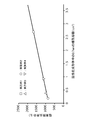
細孔径0.679nm以上0.733nm以下の細孔において、遊離塩素が除去される作用について説明する。本願発明者らは、図3に示すように、浄水カートリッジ20に含まれる細孔径0.679nm以上0.733nm以下の細孔容積と、塩素除去寿命との間に正の相関関係があることを新たに見出した。なお、図3のグラフ中、各プロットは後述する実施例1~実施例4の活性炭において得られたデータに対応する。一方、カートリッジに含まれる細孔径0.679nm以下の細孔径を有する細孔の細孔容積と、塩素除去寿命との間には相関関係がみられなかった。また、カートリッジに含まれる細孔径0.733nm以上の細孔径を有する細孔の細孔容積と、塩素除去寿命との間には相関関係がみられなかった。なお、この塩素除去寿命は、JIS S3201に準拠して測定した、ろ過流量2.5L/minの通水条件下で濃度2ppmの遊離塩素含有水を連続通水した際の遊離塩素除去率が80%に低下するまでの累積通水量として求めた。
細孔径0.679nm以上0.733nm以下の細孔が、塩素除去作用に有効である理由は定かではないが、次のように推察される。第一原理分子動力学法により水和構造計算を行い、次亜塩素酸イオンの中心から、水分子の酸素の中心までの距離(r)の動径分布(RDF)を算出すると、図4のグラフに示すように溶媒和イオン半径約3.2Å(0.32nm)付近にピークを有することが示された。つまり、親水性の次亜塩素酸イオンM1は、水中において周囲に水分子M2を伴って直径約0.64nmの水和構造を形成していると考えられる(図5A、図5B、図5C参照)。図5Aに示すように、この水和構造を形成した次亜塩素酸イオンM1は、細孔径0.679nm未満の細孔25Aの内部に進入しにくく、細孔径0.679nm未満の細孔25Aによる遊離塩素の除去作用は小さいと考えられる。図5Cに示すように、この水和構造を形成した次亜塩素酸イオンM1は、細孔径0.733nm超の細孔25Cの内部に進入することが許容され得る。しかし、細孔25Cは水和構造を形成した次亜塩素酸イオンM1に対して細孔径が大きすぎるため、細孔25Cの内壁と内部に進入した次亜塩素酸イオンM1との距離が大きくなり、活性炭による遊離塩素の吸着や酸化分解が十分に促進されないと考えられる。また、浄水カートリッジ20のようにろ過流量が大きい条件(例えば空間速度(SV)が3500/h以上)で使用される場合には、細孔径0.733nm超の細孔25Cでは水和構造を有する次亜塩素酸イオンM1を十分に捕捉しておくことができないものと推測される。一方、細孔径0.679nm以上0.733nm以下の細孔25Bは、図5Bに示すように、好適に水和構造を有する次亜塩素酸イオンM1を補足して、遊離塩素の吸着や酸化分解が促進されると考えられる。
続いて、本実施形態の一態様である、BET-DFT法により測定される、細孔径0.7nmの細孔容積が0.1967cm3/g以上である活性炭を含んでなる活性炭成形体21を備えた浄水カートリッジ20について説明する。
浄水カートリッジ20は、活性炭成形体21の体積が37.6cm3以下であることが好ましい。活性炭成形体21の体積の下限値は、特に定めるものではないが、31.8cm3以上とすることができる。さらに、浄水カートリッジ20は、JIS S3201に準拠した測定方法により測定した、ろ過流量2.5L/minの通水条件下で濃度2ppmの遊離塩素含有水を連続通水した際の遊離塩素除去率が80%に低下するまでの累積通水量が、活性炭成形体の体積1cm3当たり37.7L以上であることが好ましい。このような塩素除去寿命が長い活性炭を用いた浄水カートリッジ20は、十分な塩素除去寿命を確保しつつ、従来の浄水カートリッジより小型化可能である。
この活性炭成形体21の体積及び単位体積当たりの累積通水量は、本願発明者らが別に得た、塩素除去寿命Lが、活性炭成形体の体積Vの2乗に比例するとの知見に基づき算出されたものである。この知見に基づき、細孔径0.7nmの細孔容積が異なる活性炭について、活性炭の体積37.6cm3のカートリッジを作成して、JIS S3201に準拠して通水試験を行って比例定数を算出し、活性炭成形体の体積と塩素除去寿命との関係式を導き出した。図7において実施例1と記された太い実線のグラフが、細孔径0.7nmの細孔容積が0.1967cm3/gの活性炭における関係式(L=1.1880×V2)を表すグラフである。この関係式から、本実施形態の活性炭成形体21の体積と、活性炭成形体1cm3当たり累積通水量を算出した。なお、図7において、各グラフにプロットされた、活性炭成形体の体積19.3cm3、24.8cm3、30.1cm3、44.8cm3、52.5cm3における塩素除去寿命は、上記の関係式に基づき算出された理論値である。
本実施形態に係る活性炭成形体を実施例により具体的に説明するが、本発明はこれに限定されるものではない。
1.活性炭(実施例1~実施例4)
(1)比表面積、全細孔容積、細孔径0.7nmの細孔容積、細孔分布
実施例1~実施例4の活性炭は、表1に示す比表面積、全細孔容積、細孔径0.7nmの細孔容積であった。この比表面積、全細孔容積、細孔径0.7nmの細孔容積は、次のようにして測定した。
まず、活性炭0.1gを380℃にて真空加熱した後、Surface Area Porosity Analyzer(マイクロメリティックス社製、ASAP-2020)を用いて、窒素ガスを吸着させて吸着等温線を求め、BET法により比表面積(m2/g)を算出した。そして、この吸着等温線から細孔直径300nm以下の細孔の全細孔容積(cm3/g)を算出した。
活性炭1g当たりの細孔径0.7nmの細孔容積は、上述の実施形態に記載したようにBET-DFT法により算出した。実施例1の細孔径0.7nmの細孔容積は、0.1967cm3/gであった。実施例2の細孔径0.7nmの細孔容積は、0.0177cm3/gであった。実施例3の細孔径0.7nmの細孔容積は、0.0475cm3/gであった。実施例4の細孔径0.7nmの細孔容積は、0.1166cm3/gであった。
また、BET-DFT法により所定の細孔径の細孔容積を算出し、細孔分布を求めた。その結果を、図6に示す。図6のグラフは、横軸が細孔径(nm)を示し、縦軸が細孔容積(cm3/g)を示す。
(1)比表面積、全細孔容積、細孔径0.7nmの細孔容積、細孔分布
実施例1~実施例4の活性炭は、表1に示す比表面積、全細孔容積、細孔径0.7nmの細孔容積であった。この比表面積、全細孔容積、細孔径0.7nmの細孔容積は、次のようにして測定した。
まず、活性炭0.1gを380℃にて真空加熱した後、Surface Area Porosity Analyzer(マイクロメリティックス社製、ASAP-2020)を用いて、窒素ガスを吸着させて吸着等温線を求め、BET法により比表面積(m2/g)を算出した。そして、この吸着等温線から細孔直径300nm以下の細孔の全細孔容積(cm3/g)を算出した。
活性炭1g当たりの細孔径0.7nmの細孔容積は、上述の実施形態に記載したようにBET-DFT法により算出した。実施例1の細孔径0.7nmの細孔容積は、0.1967cm3/gであった。実施例2の細孔径0.7nmの細孔容積は、0.0177cm3/gであった。実施例3の細孔径0.7nmの細孔容積は、0.0475cm3/gであった。実施例4の細孔径0.7nmの細孔容積は、0.1166cm3/gであった。
また、BET-DFT法により所定の細孔径の細孔容積を算出し、細孔分布を求めた。その結果を、図6に示す。図6のグラフは、横軸が細孔径(nm)を示し、縦軸が細孔容積(cm3/g)を示す。
(2)真密度、嵩密度
実施例1~実施例4の活性炭は、表1に示す真密度、嵩密度であった。活性炭の真密度(cm3/g)は、JIS Z 8807の比重瓶による密度及び比重の測定方法に従い、測定液に1-ブタノールを用いて求めた。活性炭の嵩密度(cm3/g)は、以下の式により求めた。
嵩密度=真密度/{1+(全細孔容積×真密度)}
実施例1~実施例4の活性炭は、表1に示す真密度、嵩密度であった。活性炭の真密度(cm3/g)は、JIS Z 8807の比重瓶による密度及び比重の測定方法に従い、測定液に1-ブタノールを用いて求めた。活性炭の嵩密度(cm3/g)は、以下の式により求めた。
嵩密度=真密度/{1+(全細孔容積×真密度)}

2.浄水カートリッジ(実施例1~実施例4)
(1)実施例1~実施例3の活性炭(粒子状)を用いた浄水カートリッジの作製
実施例1~実施例3の活性炭を含むスラリーに、吸引ポンプに接続された中芯を投入し、吸引ポンプを作動して活性炭を中芯の周囲に付着させた。そして、活性炭が付着した中芯を乾燥機にて十分乾燥させた後、外径24.5mm×内径8.3mm×長さ90mm、体積37.6cm3の円筒形状に成形し、活性炭成形体を得た。なお、中芯は、SiO2を主成分とした多孔質セラミックによって作製されたものを用いた。得られた活性炭成形体の外周面に透水性を有する不織布を巻き、さらに、円筒形状の活性炭成形体の長手方向の一端側に、一端側の面を完全に閉塞できる円形状のキャップを装着させ、他端側に中心部分が開口した円形状のキャップを装着させることで、浄水カートリッジを作製した。
(1)実施例1~実施例3の活性炭(粒子状)を用いた浄水カートリッジの作製
実施例1~実施例3の活性炭を含むスラリーに、吸引ポンプに接続された中芯を投入し、吸引ポンプを作動して活性炭を中芯の周囲に付着させた。そして、活性炭が付着した中芯を乾燥機にて十分乾燥させた後、外径24.5mm×内径8.3mm×長さ90mm、体積37.6cm3の円筒形状に成形し、活性炭成形体を得た。なお、中芯は、SiO2を主成分とした多孔質セラミックによって作製されたものを用いた。得られた活性炭成形体の外周面に透水性を有する不織布を巻き、さらに、円筒形状の活性炭成形体の長手方向の一端側に、一端側の面を完全に閉塞できる円形状のキャップを装着させ、他端側に中心部分が開口した円形状のキャップを装着させることで、浄水カートリッジを作製した。
(2)実施例4の活性炭(繊維状)を用いた浄水カートリッジの作製
実施例4の活性炭を中芯の周りに巻き回して、外径24.5mm×内径8.3mm×長さ90mm、体積37.6cm3の円筒形状の活性炭成形体を得た。その他は、実施例1~実施例3と同様にして浄水カートリッジを作製した。
実施例4の活性炭を中芯の周りに巻き回して、外径24.5mm×内径8.3mm×長さ90mm、体積37.6cm3の円筒形状の活性炭成形体を得た。その他は、実施例1~実施例3と同様にして浄水カートリッジを作製した。
(3)活性炭の重量、活性炭成形体における活性炭の充填率
活性炭の重量Wは、浄水カートリッジ(活性炭成形体)に含まれる活性炭全体の重さとして求めた。活性炭成形体における活性炭の充填率は、活性炭成形体の体積Vに対する活性炭の体積(細孔を含む)の比率である。細孔を含む活性炭の体積は、活性炭の重量Wを活性炭の嵩密度で除して求めた。その結果を、表2に示す。
(4)活性炭成形体における細孔径0.7nmの細孔容積
得られた浄水カートリッジについて、活性炭成形体中の細孔径0.7nmの細孔容積と、活性炭成形体1cm3当たりの細孔径0.7nmの細孔容積を算出した。活性炭成形体中の細孔径0.7nmの細孔容積Y(cm3)は、活性炭1g当たりの細孔径0.7nmの細孔容積X(cm3/g)に浄水カートリッジの活性炭の重量W(g)を乗じて算出した(Y=X×W)。また、活性炭成形体1cm3当たりの細孔径0.7nmの細孔容積Z(cm3/cm3)は、活性炭成形体中の細孔径0.7nmの細孔容積Y(cm3)を活性炭成形体の体積V(cm3)で除して算出した(Z=Y/V)。その結果を、表2に示す。
活性炭の重量Wは、浄水カートリッジ(活性炭成形体)に含まれる活性炭全体の重さとして求めた。活性炭成形体における活性炭の充填率は、活性炭成形体の体積Vに対する活性炭の体積(細孔を含む)の比率である。細孔を含む活性炭の体積は、活性炭の重量Wを活性炭の嵩密度で除して求めた。その結果を、表2に示す。
(4)活性炭成形体における細孔径0.7nmの細孔容積
得られた浄水カートリッジについて、活性炭成形体中の細孔径0.7nmの細孔容積と、活性炭成形体1cm3当たりの細孔径0.7nmの細孔容積を算出した。活性炭成形体中の細孔径0.7nmの細孔容積Y(cm3)は、活性炭1g当たりの細孔径0.7nmの細孔容積X(cm3/g)に浄水カートリッジの活性炭の重量W(g)を乗じて算出した(Y=X×W)。また、活性炭成形体1cm3当たりの細孔径0.7nmの細孔容積Z(cm3/cm3)は、活性炭成形体中の細孔径0.7nmの細孔容積Y(cm3)を活性炭成形体の体積V(cm3)で除して算出した(Z=Y/V)。その結果を、表2に示す。
(5)塩素除去寿命の測定
塩素除去寿命は、株式会社LIXIL製の浄水器内蔵水栓「JF-AB461SYX(JW)」に浄水カートリッジを装着し、JIS S3201に準拠した測定方法により測定した、ろ過流量2.5L/minの通水条件下で濃度2ppmの遊離塩素含有水を連続通水した際の遊離塩素除去率が80%に低下するまでの累積通水量として求めた。通水時の印加水圧は、2.5L/minの流速を確保できるように表2のとおりに調整した。なお、印加水圧がほぼ同じになるように浄水カートリッジ中の活性炭の粒度や活性炭成形体の充填率などを制御して圧力損失を調整した。また、通水試験時の空間速度(SV)は3989/hである。通水試験は、実施例毎に3本の浄水カートリッジについて行い、3回の通水試験により求められた塩素除去寿命の平均値を各実施例における浄水カートリッジの塩素除去寿命とした。その結果を、表2に示す。
塩素除去寿命は、株式会社LIXIL製の浄水器内蔵水栓「JF-AB461SYX(JW)」に浄水カートリッジを装着し、JIS S3201に準拠した測定方法により測定した、ろ過流量2.5L/minの通水条件下で濃度2ppmの遊離塩素含有水を連続通水した際の遊離塩素除去率が80%に低下するまでの累積通水量として求めた。通水時の印加水圧は、2.5L/minの流速を確保できるように表2のとおりに調整した。なお、印加水圧がほぼ同じになるように浄水カートリッジ中の活性炭の粒度や活性炭成形体の充填率などを制御して圧力損失を調整した。また、通水試験時の空間速度(SV)は3989/hである。通水試験は、実施例毎に3本の浄水カートリッジについて行い、3回の通水試験により求められた塩素除去寿命の平均値を各実施例における浄水カートリッジの塩素除去寿命とした。その結果を、表2に示す。

3.活性炭成形体中の細孔径0.7nmの細孔容積と塩素除去寿命との関係
活性炭成形体中の細孔径0.7nmの細孔容積と塩素除去寿命とは、図3に示すような正の相関関係を有することが分かった。この結果から、細孔径0.7nmの細孔が遊離塩素除去に有効であることが示された。
活性炭成形体中の細孔径0.7nmの細孔容積と塩素除去寿命とは、図3に示すような正の相関関係を有することが分かった。この結果から、細孔径0.7nmの細孔が遊離塩素除去に有効であることが示された。
4.実施例1~実施例4の活性炭の細孔分布
図6のグラフに示されるように、実施例1の活性炭は0.733nmに細孔分布のピークがあり、細孔径0.679nm以上0.733nm以下の細孔容積が0.1967cm3/gであった。この実施例1の活性炭を用いた浄水カートリッジは、実施例2、実施例3、実施例4の活性炭より、細孔径0.679nm以上0.733nm以下の細孔容積が大きく、浄水カートリッジに用いた場合の塩素除去寿命が長かった。また、実施例4の活性炭も0.733nmに細孔分布のピークがあり、実施例1の活性炭の次に浄水カートリッジに用いた場合の塩素除去寿命が長かった。これらの結果から、細孔径0.679nm以上0.733nm以下の細孔が塩素除去に有効であることが示唆された。また、細孔分布において、細孔径0.679nm~0.733nmに細孔容積のピークを有する活性炭において塩素除去性能が高いことが示された。
また、実施例2と実施例3の活性炭は、細孔径0.679nm未満に細孔容積のピークを有するが、これらの活性炭は実施例1及び実施例4の活性炭より塩素除去寿命が短かった。この結果から、細孔径0.679nm未満の細孔が塩素除去に有効でないことが示唆された。
図6のグラフに示されるように、実施例1の活性炭は0.733nmに細孔分布のピークがあり、細孔径0.679nm以上0.733nm以下の細孔容積が0.1967cm3/gであった。この実施例1の活性炭を用いた浄水カートリッジは、実施例2、実施例3、実施例4の活性炭より、細孔径0.679nm以上0.733nm以下の細孔容積が大きく、浄水カートリッジに用いた場合の塩素除去寿命が長かった。また、実施例4の活性炭も0.733nmに細孔分布のピークがあり、実施例1の活性炭の次に浄水カートリッジに用いた場合の塩素除去寿命が長かった。これらの結果から、細孔径0.679nm以上0.733nm以下の細孔が塩素除去に有効であることが示唆された。また、細孔分布において、細孔径0.679nm~0.733nmに細孔容積のピークを有する活性炭において塩素除去性能が高いことが示された。
また、実施例2と実施例3の活性炭は、細孔径0.679nm未満に細孔容積のピークを有するが、これらの活性炭は実施例1及び実施例4の活性炭より塩素除去寿命が短かった。この結果から、細孔径0.679nm未満の細孔が塩素除去に有効でないことが示唆された。
5.カートリッジに含まれる活性炭の体積と塩素除去寿命との関係
実施例1~実施例4の活性炭について、浄水カートリッジに含まれる活性炭成形体の体積Vと塩素除去寿命Lの関係式を導きだした。この関係式を表すグラフを図7に示す。図7のグラフより、基準値として設定される塩素除去寿命1200Lにおいて、実施例1の活性炭を用いることが浄水カートリッジの小型化に有利であることが示された。また、実施例1の活性炭より細孔径0.7nmの細孔容積が大きい活性炭を用いることで、十分な遊離塩素除去性能を有する小型の浄水カートリッジを実現可能であることが示唆された。
実施例1~実施例4の活性炭について、浄水カートリッジに含まれる活性炭成形体の体積Vと塩素除去寿命Lの関係式を導きだした。この関係式を表すグラフを図7に示す。図7のグラフより、基準値として設定される塩素除去寿命1200Lにおいて、実施例1の活性炭を用いることが浄水カートリッジの小型化に有利であることが示された。また、実施例1の活性炭より細孔径0.7nmの細孔容積が大きい活性炭を用いることで、十分な遊離塩素除去性能を有する小型の浄水カートリッジを実現可能であることが示唆された。
本発明は上記で詳述した実施形態に限定されず、本発明の請求項に示した範囲で様々な変形又は変更が可能である。
例えば、活性炭成形体の形状は、円筒状に限られず、また、活性炭成形体は中芯を備えていなくても構わない。
例えば、活性炭成形体の形状は、円筒状に限られず、また、活性炭成形体は中芯を備えていなくても構わない。
20…浄水カートリッジ
21…活性炭成形体
21…活性炭成形体
Claims (5)
- 浄水カートリッジに用いられる遊離塩素除去用の活性炭であって、
BET-DFT法により測定される、細孔径0.679nm以上0.733nm以下の細孔容積が0.0177cm3/g以上である活性炭。 - 前記細孔容積が、0.0475cm3/g以上である請求項1に記載の活性炭。
- 前記細孔容積が、0.1967cm3/g以上である請求項1に記載の活性炭。
- 請求項3の活性炭を含んでなる活性炭成形体を備えた浄水カートリッジであって、
前記活性炭成形体の体積が37.6cm3以下である浄水カートリッジ。 - 請求項3の活性炭を含んでなる活性炭成形体を備えた浄水カートリッジであって、
JIS S3201に準拠した測定方法により測定した、ろ過流量2.5L/minの通水条件下で濃度2ppmの遊離塩素含有水を連続通水した際の遊離塩素除去率が80%に低下するまでの累積通水量が、前記活性炭成形体の体積1cm3当たり37.7L以上である浄水カートリッジ。
Applications Claiming Priority (2)
| Application Number | Priority Date | Filing Date | Title |
|---|---|---|---|
| JP2019060237A JP7300640B2 (ja) | 2019-03-27 | 2019-03-27 | 浄水カートリッジ |
| JP2019-060237 | 2019-03-27 |
Publications (1)
| Publication Number | Publication Date |
|---|---|
| WO2020195116A1 true WO2020195116A1 (ja) | 2020-10-01 |
Family
ID=72609769
Family Applications (1)
| Application Number | Title | Priority Date | Filing Date |
|---|---|---|---|
| PCT/JP2020/002961 Ceased WO2020195116A1 (ja) | 2019-03-27 | 2020-01-28 | 活性炭及び浄水カートリッジ |
Country Status (2)
| Country | Link |
|---|---|
| JP (1) | JP7300640B2 (ja) |
| WO (1) | WO2020195116A1 (ja) |
Families Citing this family (1)
| Publication number | Priority date | Publication date | Assignee | Title |
|---|---|---|---|---|
| JP7453462B1 (ja) | 2023-11-29 | 2024-03-19 | 大阪ガスケミカル株式会社 | 炭素質材料及びその製造方法、吸着フィルター、浄水器カートリッジ、浄水器、並びに水浄化設備 |
Citations (4)
| Publication number | Priority date | Publication date | Assignee | Title |
|---|---|---|---|---|
| JPH09110409A (ja) * | 1995-10-18 | 1997-04-28 | Kanebo Ltd | 有機塩素化合物吸着用活性炭 |
| JP2003171111A (ja) * | 2001-12-04 | 2003-06-17 | Nippon Telegr & Teleph Corp <Ntt> | 水素貯蔵用炭素材料 |
| JP2007186403A (ja) * | 2005-10-27 | 2007-07-26 | Showa Denko Kk | 活性炭、その製造方法及び用途 |
| WO2018116859A1 (ja) * | 2016-12-19 | 2018-06-28 | 株式会社アドール | 活性炭及びその製造方法 |
-
2019
- 2019-03-27 JP JP2019060237A patent/JP7300640B2/ja active Active
-
2020
- 2020-01-28 WO PCT/JP2020/002961 patent/WO2020195116A1/ja not_active Ceased
Patent Citations (4)
| Publication number | Priority date | Publication date | Assignee | Title |
|---|---|---|---|---|
| JPH09110409A (ja) * | 1995-10-18 | 1997-04-28 | Kanebo Ltd | 有機塩素化合物吸着用活性炭 |
| JP2003171111A (ja) * | 2001-12-04 | 2003-06-17 | Nippon Telegr & Teleph Corp <Ntt> | 水素貯蔵用炭素材料 |
| JP2007186403A (ja) * | 2005-10-27 | 2007-07-26 | Showa Denko Kk | 活性炭、その製造方法及び用途 |
| WO2018116859A1 (ja) * | 2016-12-19 | 2018-06-28 | 株式会社アドール | 活性炭及びその製造方法 |
Also Published As
| Publication number | Publication date |
|---|---|
| JP2020157242A (ja) | 2020-10-01 |
| JP7300640B2 (ja) | 2023-06-30 |
Similar Documents
| Publication | Publication Date | Title |
|---|---|---|
| JP6283435B2 (ja) | 活性炭成型体およびそれを用いた浄水器 | |
| CN102026720B (zh) | 过滤介质及包括所述过滤介质的水过滤系统 | |
| CN102510836B (zh) | 净水器 | |
| US8277654B2 (en) | Water purification apparatus and system | |
| KR20190119614A (ko) | 클로라민 및 염소 제거 물질 및 이의 제조 방법 | |
| US7429326B2 (en) | Water purification apparatus and system | |
| TWI549734B (zh) | 淨水濾心、淨水器以及濾材 | |
| JP4064309B2 (ja) | 浄水器 | |
| WO2015186831A1 (ja) | 浄水カートリッジ及び浄水器 | |
| JP2019098324A (ja) | 極性物質吸着活性炭 | |
| JP3164470U (ja) | 浄水器用フィルター、及びこれを用いた浄水器 | |
| JP6726520B2 (ja) | 活性炭成形体及び浄水カートリッジ | |
| WO2003022425A1 (en) | Composite particulate article and method for preparation thereof | |
| US7229552B1 (en) | Water purification apparatus and system | |
| JP6182819B2 (ja) | 浄水カートリッジ、浄水器 | |
| WO2020195116A1 (ja) | 活性炭及び浄水カートリッジ | |
| JPH11151484A (ja) | フィルターカートリッジ | |
| JPWO2007060923A1 (ja) | 流体浄化装置及びフィルターハウジング | |
| JP3693544B2 (ja) | 活性炭およびそれを備えた浄水器 | |
| JP2010269225A (ja) | 陰イオン吸着剤成型体およびそれを用いた浄水器 | |
| JP2005000768A (ja) | 浄水カートリッジ | |
| JP2001079541A (ja) | 水処理器用フィルター | |
| JP2002263637A (ja) | 浄水ユニット | |
| JP2005001681A (ja) | カートリッジの保存方法及び浄水器 | |
| JP4622576B2 (ja) | 浄水器、およびそれを用いた浄水システム、浄水方法 |
Legal Events
| Date | Code | Title | Description |
|---|---|---|---|
| 121 | Ep: the epo has been informed by wipo that ep was designated in this application |
Ref document number: 20778419 Country of ref document: EP Kind code of ref document: A1 |
|
| NENP | Non-entry into the national phase |
Ref country code: DE |
|
| 122 | Ep: pct application non-entry in european phase |
Ref document number: 20778419 Country of ref document: EP Kind code of ref document: A1 |