WO2020189537A1 - 濾材及びフィルターユニット - Google Patents
濾材及びフィルターユニット Download PDFInfo
- Publication number
- WO2020189537A1 WO2020189537A1 PCT/JP2020/010999 JP2020010999W WO2020189537A1 WO 2020189537 A1 WO2020189537 A1 WO 2020189537A1 JP 2020010999 W JP2020010999 W JP 2020010999W WO 2020189537 A1 WO2020189537 A1 WO 2020189537A1
- Authority
- WO
- WIPO (PCT)
- Prior art keywords
- filter medium
- fiber
- fiber sheet
- mass
- filter
- Prior art date
Links
Images


Classifications
-
- B—PERFORMING OPERATIONS; TRANSPORTING
- B01—PHYSICAL OR CHEMICAL PROCESSES OR APPARATUS IN GENERAL
- B01D—SEPARATION
- B01D39/00—Filtering material for liquid or gaseous fluids
- B01D39/14—Other self-supporting filtering material ; Other filtering material
- B01D39/16—Other self-supporting filtering material ; Other filtering material of organic material, e.g. synthetic fibres
- B01D39/1607—Other self-supporting filtering material ; Other filtering material of organic material, e.g. synthetic fibres the material being fibrous
- B01D39/1623—Other self-supporting filtering material ; Other filtering material of organic material, e.g. synthetic fibres the material being fibrous of synthetic origin
-
- B—PERFORMING OPERATIONS; TRANSPORTING
- B01—PHYSICAL OR CHEMICAL PROCESSES OR APPARATUS IN GENERAL
- B01D—SEPARATION
- B01D39/00—Filtering material for liquid or gaseous fluids
- B01D39/14—Other self-supporting filtering material ; Other filtering material
- B01D39/16—Other self-supporting filtering material ; Other filtering material of organic material, e.g. synthetic fibres
- B01D39/18—Other self-supporting filtering material ; Other filtering material of organic material, e.g. synthetic fibres the material being cellulose or derivatives thereof
-
- B—PERFORMING OPERATIONS; TRANSPORTING
- B01—PHYSICAL OR CHEMICAL PROCESSES OR APPARATUS IN GENERAL
- B01D—SEPARATION
- B01D46/00—Filters or filtering processes specially modified for separating dispersed particles from gases or vapours
- B01D46/52—Particle separators, e.g. dust precipitators, using filters embodying folded corrugated or wound sheet material
- B01D46/521—Particle separators, e.g. dust precipitators, using filters embodying folded corrugated or wound sheet material using folded, pleated material
-
- B—PERFORMING OPERATIONS; TRANSPORTING
- B32—LAYERED PRODUCTS
- B32B—LAYERED PRODUCTS, i.e. PRODUCTS BUILT-UP OF STRATA OF FLAT OR NON-FLAT, e.g. CELLULAR OR HONEYCOMB, FORM
- B32B5/00—Layered products characterised by the non- homogeneity or physical structure, i.e. comprising a fibrous, filamentary, particulate or foam layer; Layered products characterised by having a layer differing constitutionally or physically in different parts
- B32B5/22—Layered products characterised by the non- homogeneity or physical structure, i.e. comprising a fibrous, filamentary, particulate or foam layer; Layered products characterised by having a layer differing constitutionally or physically in different parts characterised by the presence of two or more layers which are next to each other and are fibrous, filamentary, formed of particles or foamed
- B32B5/24—Layered products characterised by the non- homogeneity or physical structure, i.e. comprising a fibrous, filamentary, particulate or foam layer; Layered products characterised by having a layer differing constitutionally or physically in different parts characterised by the presence of two or more layers which are next to each other and are fibrous, filamentary, formed of particles or foamed one layer being a fibrous or filamentary layer
- B32B5/26—Layered products characterised by the non- homogeneity or physical structure, i.e. comprising a fibrous, filamentary, particulate or foam layer; Layered products characterised by having a layer differing constitutionally or physically in different parts characterised by the presence of two or more layers which are next to each other and are fibrous, filamentary, formed of particles or foamed one layer being a fibrous or filamentary layer another layer next to it also being fibrous or filamentary
-
- B—PERFORMING OPERATIONS; TRANSPORTING
- B01—PHYSICAL OR CHEMICAL PROCESSES OR APPARATUS IN GENERAL
- B01D—SEPARATION
- B01D2239/00—Aspects relating to filtering material for liquid or gaseous fluids
- B01D2239/02—Types of fibres, filaments or particles, self-supporting or supported materials
-
- B—PERFORMING OPERATIONS; TRANSPORTING
- B01—PHYSICAL OR CHEMICAL PROCESSES OR APPARATUS IN GENERAL
- B01D—SEPARATION
- B01D2239/00—Aspects relating to filtering material for liquid or gaseous fluids
- B01D2239/06—Filter cloth, e.g. knitted, woven non-woven; self-supported material
- B01D2239/065—More than one layer present in the filtering material
-
- Y—GENERAL TAGGING OF NEW TECHNOLOGICAL DEVELOPMENTS; GENERAL TAGGING OF CROSS-SECTIONAL TECHNOLOGIES SPANNING OVER SEVERAL SECTIONS OF THE IPC; TECHNICAL SUBJECTS COVERED BY FORMER USPC CROSS-REFERENCE ART COLLECTIONS [XRACs] AND DIGESTS
- Y02—TECHNOLOGIES OR APPLICATIONS FOR MITIGATION OR ADAPTATION AGAINST CLIMATE CHANGE
- Y02A—TECHNOLOGIES FOR ADAPTATION TO CLIMATE CHANGE
- Y02A50/00—TECHNOLOGIES FOR ADAPTATION TO CLIMATE CHANGE in human health protection, e.g. against extreme weather
- Y02A50/20—Air quality improvement or preservation, e.g. vehicle emission control or emission reduction by using catalytic converters
- Y02A50/2351—Atmospheric particulate matter [PM], e.g. carbon smoke microparticles, smog, aerosol particles, dust
Definitions
- the present invention relates to a filter medium that can be used as an air filter for general industry, air conditioners, air purifiers, vacuum cleaners, automobiles, etc., and a filter unit provided with the filter medium.
- Air filters and air purifiers used in buildings, factories, automobiles, general households, etc. use air filters with filter media loaded in the frame.
- Such a filter is subjected to a mountain valley-shaped process called pleating process to increase the filtration area so that more filter media can be loaded within the limited dimensions.
- the shape is maintained by applying a string-shaped resin part (bead) containing hot melt resin extending in the direction intersecting the ridgeline of the mountain part of the pleats to the pleated filter medium, and the gap between the pleats is maintained. Is secured, and the one combined with the frame is used as the filter unit.
- Such a pleated filter medium is obtained by laminating a plurality of fiber sheets having different densities in order to maintain the strength as an air filter, to achieve high collection and reduction of pressure loss (low pressure loss). Is often used.
- the filter medium obtained by laminating a plurality of fiber sheets includes, for example, a fiber sheet (aggregate layer) for imparting strength as an air filter and a fiber sheet (dust collection layer) for collecting particles in the air. It is a filter medium in which In particular, the fiber sheet used as the aggregate layer is required to have high strength and low pressure loss.
- the pressure loss of the filter unit in which the pleated filter medium is loaded into the frame is the pressure loss due to the ventilation resistance of the filter medium itself (filter medium pressure loss) and the pressure loss due to the structure caused by the deformation of the pleated filter medium due to wind pressure (structural pressure loss). It consists of.
- structural pressure loss means that when air is passed through the filter media, the filter media expands and deforms due to the wind pressure on the filter media, narrowing the width of the air flow path sandwiched between adjacent pleated filter media, and the filter media come into contact with each other. This is caused by the difficulty of air flow. Therefore, in order to reduce structural pressure loss, a filter medium having a thin thickness and being hard to bend has been studied.
- Patent Document 1 has a non-woven fabric mainly composed of organic fibers in which single fibers are fixed as a practical filter medium suitable for high wind velocity filtration and capable of mini-pleating with high air permeability and thin filter medium thickness.
- the non-woven fabric is composed of a plurality of single fibers having different young ratios and fineness, and contains at least non-crimped single fibers having a Young ratio of 150 cN / dtex or more and a fineness of 7 dtex or more at a ratio of 20% or more of the total fiber mass.
- the single fibers are fixed with a resin having a glass transition temperature of 30 ° C. or higher, the specific strength at 1% elongation is 1000 N ⁇ cm / g or more, and the air permeability is 100 cm 3 / cm 2 ⁇ sec.
- the above-mentioned filter medium is disclosed.
- Patent Document 2 it is advantageous to add short glass fibers to the aggregate layer of the filter medium for the filter because it has high strength and can reduce the pressure loss.
- the filter material containing the glass fibers is pleated, the fluffing of the glass fibers occurs. It is described that it will be a problem.
- the filter medium as a filter medium for a filter containing short glass fibers and less fluffing, the filter medium contains two or more layers of sheets, and at least the first sheet contains short glass fibers, organic short fibers and a binder resin.
- the organic short fibers include those having a fiber diameter of at least 1 to 20 ⁇ m, and the organic short fibers having a fiber diameter of 1 to 20 ⁇ m are at least 25% by mass with respect to the glass short fibers, and the second sheet.
- a filter medium for a filter characterized in that is an electlet-processed non-woven fabric sheet, is disclosed.
- the structural pressure loss in the pleated filter medium folded so that the peaks and valleys are alternately continuous is that when air is passed through the filter medium, the filter medium expands and deforms due to the wind pressure on the filter medium. , It occurs because the width of the air flow path sandwiched between adjacent pleated filter media is narrowed, and the filter media come into contact with each other, making it difficult for air to flow. Therefore, when the pitch between adjacent mountain portions is as short as 5.0 mm or less or 3.5 mm or less, the air flow path is narrow and the pressure loss during ventilation becomes particularly large.
- Patent Document 1 it is considered to suppress the pressure loss by using a pleated filter medium having a height of 8 mm in the pleated portion, but the pitch of the pleated peak portion is not described. .. Patent Document 2 does not describe or suggest the problem that the pressure loss becomes large in the filter medium having a short pitch of the mountain portion of the pleated filter medium and the means for solving this problem.
- one or more embodiments of the present invention provide pressure loss during ventilation in a pleated filter medium in which peaks and valleys are alternately continuous and the pitch of the peaks on at least one surface is 5.0 mm or less. The purpose is to reduce.
- One or more embodiments of the present invention for achieving the above object have any of the following configurations.
- the thickness of the filter medium is 0.10 mm to 0.43 mm.
- the filter medium according to (1) which has a shape located on a curve.
- the filter medium according to one or more embodiments of the present invention and the filter unit using the same have a low pressure loss even though the pitch of the pleated peaks is as short as 0.5 mm to 5.0 mm.
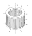
- FIG. 1 is a perspective view of a filter unit 1 including a filter medium 10 and a pair of frames 20 and 20 that support the filter medium 10.
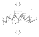
- FIG. 2 is a schematic view of a part of a cross section of the filter medium 10 in the filter unit 1 shown in FIG. 1 by a plane perpendicular to the axis C.
- FIG. 3 shows a string-shaped resin portion containing hot melt resin in a direction orthogonal to the ridge line L 1 of the mountain portion A on the side of the first surface S 1 in order to facilitate holding the pleated shape of the filter medium 10.
- Bead) R 1 is continuously applied, and a string-shaped resin portion (bead) R 2 containing hot melt resin is continuously applied in a direction orthogonal to the ridge line L 2 of the mountain portion A on the side of the second surface S 2.
- the applied filter medium 10 a schematic view of a portion of a section along the ridge line L 1, the plane perpendicular to the L 2 at the crest a.
- FIG. 4 shows a string-shaped resin portion containing a hot melt resin in a direction orthogonal to the ridge line L 1 of the mountain portion A on the side of the first surface S 1 in order to facilitate holding the pleated shape of the filter medium 10.
- Bead) R 1 is applied intermittently, and a string-shaped resin portion (bead) R 2 containing hot melt resin is intermittently applied in a direction orthogonal to the ridge line L 2 of the mountain portion A on the side of the second surface S 2.
- the applied filter medium 10 a schematic view of a portion of a section along the ridge line L 1, the plane perpendicular to the L 2 at the crest a.
- the resin portions R 1 and R 2 since the adjacent resin portions R 1 and R 2 are in contact with each other and connected to each other, the resin portions R 1 and R 2 form a single string and extend continuously.
- the filter medium of the present invention has a structure in which a first fiber sheet which is an aggregate layer and a second fiber sheet which is a dust collecting layer are laminated. Further, the filter medium of the present invention has a pleated shape in which peaks and valleys are alternately continuous. In this pleated shape, the height of the ridges is 5 mm to 50 mm, and the pitch of the ridges on at least one surface is 0.5 mm to 5.0 mm. A preferred embodiment of the pleated shape of the filter medium will be described with reference to the specific examples shown in FIGS.
- FIG. 1 is a perspective view of a filter unit 1 including a filter medium 10 and a pair of frames 20 and 20 supporting the filter medium 10.
- the filter medium 10 is formed into a cylindrical shape centered on the shaft C, and both ends thereof are fixed and sealed to the annular frames 20 and 20, respectively, with a hot melt adhesive.
- the air processed by the filter unit 1 is supplied from the outside of the filter medium 10, passes through the filter medium 10, and is discharged from the inside in the direction of the axis C.
- FIG. 2 is a schematic view of a part of a cross section of the filter medium 10 in the filter unit 1 shown in FIG. 1 by a plane perpendicular to the axis C.
- the filter medium 10 has a pleated shape in which mountain portions A and valley portions B are folded so as to be alternately continuous.
- One surface of the filter medium 10 and the first surface S 1, the rear surface of the first surface and the second surface S 2.
- the first surface S 1 is the inner peripheral surface of the filter medium 10
- the second surface S 2 is the outer peripheral surface of the filter medium 10.
- the top of the mountain portion A of the first side surface S 1 and top P 1 to the top of the mountain portion A of the second side surface S 2 with the top P 2.
- the air flow is indicated by a white arrow.
- the ridge line formed by the top P 1 is the ridge line formed by the top P 1 on the side of the first surface S 1
- the ridge line L is formed by the top P 2 on the top of the mountain portion A on the side of the second surface S 2. Let it be 2 .
- the height H of the crest A is from the top P 1 of the first side surface S 1, up to the top P 2 of the second side surface S 2, along a direction perpendicular to the plane containing the top P 1 Refers to the distance.
- the height H of the mountain portion A is preferably 5 mm to 50 mm.
- At least one of the pitch X of the mountain portion A on the first surface S1 of the filter medium 10 and the pitch Y of the mountain portion A on the second surface S2 is preferably 0.5 mm to 5.0 mm. It is preferably 0.5 mm to 3.5 mm, more preferably 0.5 mm to 3.0 mm.
- the top portion P 1 of the mountain portion A on the side of the first surface S 1 of the filter medium 10 is formed.
- the pitch X of ridges a in the first surface S 1 is typically within the predetermined range.
- the pitch Y of the mountain portion A on the second surface S2 may be within the predetermined range.
- the structural pressure drop in the pleated filter medium is particularly large when the pitch of the peaks on at least one surface is 3.5 mm or less or 3.0 mm or less, but in the present embodiment, such a short peak pitch is used. It is possible to reduce the structural pressure loss in the pleated filter medium.
- the crest A is (coincident to the axis C) extending a direction perpendicular on the section, the top P 1 of the peak portion A of the first side surface S 1 of the filter medium 10, when located on the convex curve to a second side surface S 2, the curvature radius of the curve can be, for example 200mm or less, it is 150mm or less or 120mm or less.
- Such a filter medium 10 has a problem that the pitch X of the mountain portion A on the first surface S1 is particularly small and the structural pressure loss becomes large. However, in the present embodiment, this problem can be solved by the features described later. it can.
- a convex curve extends over the entire circumference toward the second surface where the top of the mountain portion is located on the side of the first surface of the filter medium on the cross section perpendicular to the direction in which the mountain portion extends.
- It is a cylindrical filter medium that has a closed circular shape, but may have other shapes.
- the curve may be a partially open curve such as a parabola or a semicircle, or a curve having a shape closed over the entire circumference such as an ellipse or a circular or flattened ellipse. May be good.
- a string-shaped resin portion (bead) containing hot melt resin extending in the direction intersecting the ridgeline of the mountain portion is applied on one or both surfaces of the filter medium. It is preferable to form the ridge.
- the resin portion is not depicted in FIGS. 1 and 2.
- FIGS. 3 and 4 describe an embodiment of the filter medium 10 coated with the string-shaped resin portions R 1 and R 2 containing the hot melt resin extending in the direction orthogonal to the ridge lines L 1 and L 2 of the mountain portion A. Therefore, the pitch of the mountain portion A of the filter medium 10 is drawn at a pitch different from that in FIG.
- the filter medium 10 according to the embodiment shown in FIGS. 3 and 4 has the same characteristics as the filter medium 10 according to the embodiment shown in FIG. 2 except that the resin portions R 1 and R 2 are applied.
- FIG. 3 shows a string-shaped resin portion containing hot melt resin in a direction orthogonal to the ridge line L 1 of the mountain portion A on the side of the first surface S 1 in order to facilitate holding the pleated shape of the filter medium 10.
- Bead) R 1 is continuously applied, and a string-shaped resin portion (bead) R 2 containing hot melt resin is continuously applied in a direction orthogonal to the ridge line L 2 of the mountain portion A on the side of the second surface S 2.
- the applied filter medium 10 a schematic view of a portion of a section along the ridge line L 1, the plane perpendicular to the L 2 at the crest a.
- the string-shaped resin portions R 1 and R 2 extend in a direction orthogonal to the ridge lines L1 and L2 of the mountain portion A.
- FIG. 4 shows a string-shaped resin portion containing a hot melt resin in a direction orthogonal to the ridge line L 1 of the mountain portion A on the side of the first surface S 1 in order to facilitate holding the pleated shape of the filter medium 10.
- Bead) R 1 is applied intermittently, and a string-shaped resin portion (bead) R 2 containing hot melt resin is intermittently applied in a direction orthogonal to the ridge line L 2 of the mountain portion A on the side of the second surface S 2.
- the applied filter medium 10 a schematic view of a portion of a section along the ridge line L 1, the plane perpendicular to the L 2 at the crest a.
- the string-shaped resin portions R 1 and R 2 are present in the vicinity of the tops P 1 and P 2 of the mountain portion A, and are not present in the vicinity of the bottom of the valley portion B, but are adjacent mountains. Since the resin portions R 1 and R 2 applied to the portion A are in contact with each other, the resin portions R 1 and R 2 form a single string and are orthogonal to the ridge lines L 1 and L 2 of the mountain portion A. It extends in the direction.
- the string-shaped resin portions R 1 and R 2 extend in the direction orthogonal to the ridge lines L 1 and L 2 of the mountain portion A, but are limited to this embodiment. Instead, it suffices to extend in the direction intersecting the ridges L1 and L2 of the mountain portion A.
- the string-shaped resin portions R 1 and R 2 may partially or completely permeate the fiber sheet of the filter medium 10.
- a plurality of string-shaped resin portions R 1 and R 2 may be formed at different positions in the direction in which the mountain portion A extends, or only one may be formed.
- the string-shaped resin portions R 1 and R 2 may be formed over the entire circumferential direction of the axis C of the filter medium 10, or may be formed only partially. Further, a resin part R 1 string-like first on the surface S 1 of the filter medium 10, one of the string-like resin portion R 2 on the second surface S 2 of the filter medium 10 may not be present ..
- the thickness W of the string-shaped resin portions R 1 and R 2 is preferably 0.5 mm to 2.5 mm. ..
- the width of the string-shaped resin portions R 1 and R 2 in the directions of the ridges L 1 and L 2 of the mountain portion A can be, for example, 0.5 mm to 2.5 mm.
- applying hot melt resin on the filter medium in the direction intersecting the ridgeline of the mountain portion of the filter medium to form a string-shaped resin portion is referred to as "bead processing", and the formed string.
- the resin part in the shape may be referred to as a "bead”.
- the filter medium of the present invention preferably has a thickness of 0.10 mm to 0.43 mm, more preferably 0.10 mm to 0.40 mm, more preferably 0.10 mm to 0.37 mm, and 0. It is particularly preferably .10 mm to 0.34 mm.
- the thickness of the filter medium is more preferably 0.20 mm or more in the above range. When the thickness of the filter medium is within this range, the structural pressure loss is reduced.
- the thickness of the filter medium corresponds to the thickness D of the filter medium 10 shown in FIGS.
- the basis weight of the filter medium of the present invention is not particularly reduced, and can be, for example, 10 to 100 g / m 2 , preferably 20 to 80 g / m 2 .
- the filter medium of the present invention preferably has a rigidity of 1000 ⁇ N or more, more preferably 1200 ⁇ N or more, more preferably 1300 ⁇ N or more, and particularly preferably 1500 ⁇ N or more according to the Gale method.
- the pressure loss due to the structure of the pleated filter medium is determined by the balance between the thickness of the filter medium and the rigidity and softness. The thinner the thickness, the lower the pressure loss, which is preferable.
- the rigidity of the filter medium by the Gale method is at least 1000 ⁇ N. is necessary. When the rigidity of the filter medium by the Gale method is within the above range, the deformation of the filter medium is suppressed during ventilation, so that the structural pressure loss is reduced.
- the rigidity of the filter medium by the Gale method is preferably higher as long as it does not impair the pleating workability, and the upper limit is not particularly limited, but it should be 5000 ⁇ N or less in order to achieve good foldability capable of forming a sharp mountain shape. Is preferable, and typically it can be 4000 ⁇ N or less or 3500 ⁇ N or less.
- the filter medium of the present invention has a structure in which a first fiber sheet which is an aggregate layer and a second fiber sheet which is a dust collecting layer are laminated, and other sheets may be further laminated.
- the first fiber sheet and the second fiber sheet are each preferably composed of a non-woven fabric sheet.
- the filter medium 10 of the illustrated embodiment is a laminated filter medium in which a first fiber sheet 11 which is an aggregate layer and a second fiber sheet 12 which is a dust collecting layer are laminated.
- the first fiber sheet 11 is arranged on the outer peripheral side corresponding to the upstream of the air flow
- the second fiber sheet 12 is arranged on the inner peripheral side corresponding to the downstream of the air flow.
- the first fiber sheet which is the aggregate layer, aims to impart mechanical strength such as rigidity to the filter medium.
- the first fiber sheet preferably has a modulus of 50 N or more at 1% elongation.
- a filter medium containing the first fiber sheet having a modulus in this range when stretched by 1% suppresses deformation of the filter medium during ventilation, so that structural pressure loss is particularly reduced.
- the first fiber sheet preferably contains fibers and a binder resin, and preferably further contains pulp.
- Examples of the fiber contained in the first fiber sheet include one or more selected from organic fibers and inorganic fibers.
- the organic fiber include polyester fiber (PET fiber and the like), vinylon fiber, polyamide fiber, ultrahigh molecular weight polyethylene fiber, polypropylene fiber, polyaramid fiber, carbon fiber and the like.
- the organic fiber one or more kinds snooped from polyester fiber and vinylon fiber are particularly preferable.
- the inorganic fiber include glass fiber and metal fiber, and glass fiber is particularly preferable.
- Vinylon fibers include vinylon fibers produced by a water-based wet spinning method that has been used for a long time, and vinylon fibers having a high young rate produced by a newly developed solvent wet cooling gel spinning method.
- the vinylon fibers produced by the solvent wet cooling gel spinning method have a higher Young ratio and a higher elongation at break of 4 to 15% than the vinylon fibers produced by the conventionally used aqueous wet spinning method.
- the fiber contained in the first fiber sheet is preferably a non-crimped single fiber.
- the fiber accumulation in the non-woven fabric becomes flat, so that the orientation of each single fiber is one-dimensional, and there is no looseness. Therefore, when an external force is applied to the non-woven fabric, the elongation due to the looseness is small, and thus the tensile resistance force corresponding to the physical properties of the single yarn is likely to be generated immediately, which is preferable.
- the blending ratio of fibers having a Young's modulus of 200 cN / dtex or more is preferably 35% by mass or more, more preferably 38% by mass or more, more preferably 40% by mass or more, still more preferably 42% by mass or more. More preferably, it is 45% by mass or more.
- the first fiber sheet having a blending ratio of fibers having a Young's modulus of 200 cN / dtex or more in this range is particularly preferable as an aggregate layer because it has high strength and is not easily deformed, and the pressure loss of the filter medium containing the same is small.
- the upper limit of the blending ratio of fibers having a Young's modulus of 200 cN / dtex or more in the first fiber sheet is not particularly limited, but may be, for example, 70% by mass or less or 60% by mass or less.
- the fiber having a Young's modulus of 200 cN / dtex or more may be an organic fiber or an inorganic fiber, but one or more selected from vinylon fiber and glass fiber can be preferably used. More preferably, the first fiber sheet contains 5% by mass or more of organic fibers having a Young's modulus of 200 cN / dtex or more based on the total amount of the first fiber sheet.
- an organic fiber contained in the first fiber sheet particularly an organic fiber having a Young's modulus of 200 cN / dtex or more
- a fiber having a large fineness is suitable for increasing strength and bending rigidity.
- organic fibers having a fineness of 7 dtex (fiber diameter 26 ⁇ m) or more are suitable.
- the fineness is preferably in the range of 7 to 40 dtex (fiber diameter 26 to 63 ⁇ m).
- the fine fiber plays a role of joining the high-strength thick fiber.
- the organic fiber contained in the first fiber sheet a mixed fiber of a fiber having a high fineness and a fiber having a fineness is preferable.
- the fiber diameter added next to the fineness is the fiber diameter when the specific gravity of the fiber material is 1.30 g / cm 3 .
- organic fibers that form the skeleton have low collection efficiency, so fine organic fibers with a fineness of 1 to 6 dtex (fiber diameter of 10 to 24 ⁇ m) are also blended to ensure collection performance from fine particles to coarse particles and dust. It is good to control the holding amount.
- organic fibers include polyester fibers.
- the fiber length of the organic fiber contained in the first fiber sheet is not particularly limited, but the average fiber length is 5 mm or more from the viewpoint of imparting sufficient tensile strength and preventing scattering and fluffing when glass fiber is contained. Is preferable.
- the upper limit of the fiber length of the organic fiber is not particularly limited, but if the fiber length is too long, the dispersibility in water tends to deteriorate, so 30 mm or less is preferable, and 20 mm or less is more preferable.
- the fiber diameter of the glass fiber contained in the first fiber sheet is not particularly limited, but as with the organic fiber, if the fiber diameter is small, it is difficult to impart the intended strength as an aggregate layer, so that the glass fiber
- the fiber diameter is preferably 5 ⁇ m or more, more preferably 10 ⁇ m or more, more preferably 13 ⁇ m or more, and if the fiber diameter is too large, there are problems that the filter medium is difficult to bend during pleating and the surface of the filter medium has a lot of fluff.
- the fiber diameter of the above is preferably 25 ⁇ m or less, more preferably 20 ⁇ m or less, and even more preferably 15 ⁇ m or less.
- the fiber length of the glass fiber is not particularly limited, but if the fiber length is short, the number of entanglement points with the organic fiber for one glass fiber is reduced, and the glass fiber is easily scattered from the sheet.
- the average fiber length is preferably 5 mm or more, more preferably 10 mm or more, and if the fiber length is too long, the dispersibility in water tends to deteriorate, so that the average fiber length is 30 mm or less. It is preferably 20 mm or less, and more preferably 20 mm or less.
- the glass fiber is preferably 50% by mass or less, more preferably 45% by mass or less, and more preferably 40% by mass or less with respect to the total amount of the first fiber sheet.
- the first fiber sheet does not have to contain glass fibers at all, but the glass fibers are preferably 10% by mass or more, more preferably 20% by mass or more, based on the total amount of the first fiber sheet. When it is preferably 30% by mass or more, it is easy to increase the rigidity and softness of the filter medium containing the first fiber sheet, and the thickness of the first fiber sheet is reduced to reduce the pressure loss as the filter medium. Is easy.
- the first fiber sheet preferably further contains pulp.
- the pulp has a function of reducing the thickness of the first fiber sheet to reduce the pressure loss of the filter medium and a function of suppressing the popping out or fluffing of the glass fiber when the glass fiber is contained.
- the pulp content per total amount of the first fiber sheet is preferably 10% by mass or more, more preferably 15% by mass or more.
- the upper limit of the pulp content per total amount of the first fiber sheet is not particularly limited, but is preferably 30% by mass or less, and more preferably 25% by mass or less.
- the first fiber sheet contains a binder resin.
- the binder resin has a function of adhering the fibers to each other and giving the first fiber sheet strength.
- the binder resin is not particularly limited, and polyvinyl alcohol resin, vinyl acetate resin, acrylic resin, urethane resin, acrylic-styrene resin and the like can be used. In particular, it is preferable to use a polyvinyl alcohol resin or an acrylic resin as the binder resin because there is little offensive odor. Further, the binder resin is preferably 10 to 40% by mass in the first fiber sheet. If it is small, the strength of the first fiber sheet tends to decrease, and if it is large, the pressure loss of the filter medium tends to increase.
- the first fiber sheet contains pigments, dyes, colorants, water repellents, water absorbents, flame retardants, stabilizers, antioxidants, ultraviolet absorbers, metal particles, etc.
- Other components such as inorganic compound particles, crystal nucleating agents, lubricants, plasticizers, fragrances, deodorants, antibacterial agents, antifungal agents, antiviral agents, antiallergen agents, repellents, gas adsorbents, gas adsorbed porous bodies, etc. Can be added.
- the basis weight can be, for example, 10 g / m 2 to 60 g / m 2 , preferably 20 g / m 2 to 50 g / m 2 .
- the thickness can be, for example, 0.05 mm to 0.33 mm, preferably 0.10 mm to 0.30 mm.
- the method for producing the first fiber sheet is not particularly limited and can be arbitrarily selected from known methods, but the papermaking method is preferable because it is easy to mix thick and fine fibers.
- the second fiber sheet is not particularly limited as long as it is a fiber sheet having a function of collecting (collecting) particles such as dust, but is a non-woven fabric manufactured by a manufacturing method (for example, a melt blow method) capable of ultrafine particles. It is preferable to have.
- the non-woven fabric preferably uses polyolefin fibers, particularly preferably polypropylene fibers, in order to achieve even higher collection efficiency.
- the second fiber sheet is also preferably an electret-processed non-woven fabric.
- the electret processing method is not particularly limited, and a charging method arbitrarily selected from a corona discharge method, a fluid contact method, a triboelectric charging method, etc. may be applied to the non-woven fabric sheet.
- the fiber used for the electret non-woven fabric in the present invention may contain an additive for improving the charging effect by the electret processing.
- an additive for improving the charging effect by the electret processing Various types of such additives can be used, but among them, hindered amine-based additives and triazine-based additives are more preferable because static electricity can be easily maintained.
- the basis weight can be, for example, 10 g / m 2 to 50 g / m 2 , preferably 10 g / m 2 to 40 g / m 2 . be able to. Further, for the same reason, the thickness can be, for example, 0.05 mm to 0.20 mm, preferably 0.05 mm to 0.15 mm.
- the method for producing the filter medium by laminating the first fiber sheet and the second fiber sheet is not particularly limited.
- the first fiber sheet and the second fiber sheet may be simply laminated, or the first fiber sheet and the second fiber sheet are bonded to each other via an adhesive such as a heat-sealing resin or a moisture-curable resin. You may.
- the method of adhering the first fiber sheet and the second fiber sheet with an adhesive is preferable because the fiber sheets are not easily peeled off during pleating.
- a heat-sealing resin is used, a powdery adhesive is sprayed on one of the first fiber sheet and the second fiber sheet, heated in a furnace, and then laminated with the other fiber sheet. be able to.
- a method of pleating the filter medium there are methods such as a reciprocating method and a rotary method, and any of them can be used. Further, in order to maintain the pleated shape, it is preferable to perform processing using a comb for holding a gap between mountains or a separator such as a string-shaped resin part (bead), and the bead is used from the viewpoint of production efficiency. It is preferable to perform the processing (bead processing).
- the filter unit of the present invention is obtained by combining and fixing the filter medium of the present invention and a frame body that supports the filter medium.
- a sheet in which functional particles such as a fungicide, an antiallergen agent, and a gas-adsorbed porous body are impregnated or sandwiched upstream or downstream of the filter medium is fixed to the frame together with the filter medium.
- a metal frame, a non-woven fabric frame, a paper frame, or the like can be used, and any shape may be used.
- An adhesive tape, urethane adhesive, hot melt adhesive, or the like can be used to bond the frame to the filter medium, but the hot melt adhesive is preferable from the viewpoint of workability and adhesiveness.
- a pair of annular frame bodies 20 and 20 are used as the frame body, but the present invention is not limited to this example.
- ⁇ Thickness> The thickness was measured using a dial thickness gauge (TECLOCK SM-114 stylus shape 10 mm ⁇ , scale 0.01 mm, measuring force 2.5 N). The measurement was performed by sampling 5 places arbitrarily from 1 sample, and the average value was used.
- TECLOCK SM-114 stylus shape 10 mm ⁇ , scale 0.01 mm, measuring force 2.5 N The measurement was performed by sampling 5 places arbitrarily from 1 sample, and the average value was used.
- the rigidity and softness were measured by a Gale / flexibility tester manufactured by Toyo Seiki Seisakusho Co., Ltd. based on the 6.7.4 Gale method of JIS L 1913 (2010).
- the rigidity and softness of the Gale tester was determined by the following method. Five test pieces were collected with the length direction of the non-woven fabric (direction in which the non-woven fabric flows in the manufacturing process: MD direction) as the length direction of the test piece. Using the following formula, the average value of 5 test pieces, 1 time each on the front and back, was calculated and rounded to one significant digit to calculate the rigidity ( ⁇ N) of the sample.
- the stiffness by the Gale method may be referred to as "Gale stiffness” or "rigidity”.
- ⁇ Fiber sheet modulus> According to the method described in 6.3 of JIS L 1913 (2010), a sample of 5 cm ⁇ 20 cm was collected from the first fiber sheet used in Examples and Comparative Examples, and the vertical direction (nonwoven fabric flow in the manufacturing process). The modulus at 1% extension was measured by pulling at a gripping interval of 10 cm and a speed of 10 cm / min with respect to the direction (MD direction).
- the filter is set by sandwiching it between the upper and lower wind tunnels of the measuring device, closed so that air does not leak between the filter unit and the wind tunnel, and the filter unit when air is passed through with a suction processing air volume of 8.0 m 3 / min.
- the upstream and downstream differential pressure was measured with a manometer (Manostar Gauge WO81 manufactured by Yamamoto Electric Mfg. Co., Ltd.).
- the filter is set so as to be sandwiched between the upper and lower wind tunnels of the measuring device, closed so that air does not leak between the filter unit and the wind tunnel, and air is passed through with a suction processing air volume of 8.0 m 3 / min, and the filter is upstream and downstream.
- Example 1 (First fiber sheet) After producing the fiber aggregate by the wet paper making method of the inclined wire method, the fiber aggregate was impregnated with the binder resin and dried and heat-treated to prepare the first fiber sheet having a basis weight of 35 g / m 2 .
- the first fiber sheet is a first polyethylene terephthalate (PET) fiber (fineness 3.3 dtex, fiber length 10 mm, non-crimping, Young ratio 45 cN / dtex) 4% by mass, a second PET fiber (fineness 6.6 dtex).
- PET polyethylene terephthalate
- first fiber sheet of Example 1 had a modulus of 59 N and a thickness of 0.28 mm at 1% elongation.
- a non-woven fabric having a basis weight of 25 g / m 2 was prepared from polypropylene to which 1% by mass of the triazine compound "Kimasorb” (registered trademark) 944 (manufactured by Ciba Geigy Japan) was added by the melt blow method. Further, the obtained non-woven fabric was electret-processed by a fluid contact method to prepare an electret non-woven fabric. This electret non-woven fabric was used as a second fiber sheet. The thickness of the obtained second fiber sheet of Example 1 was 0.10 mm.
- the obtained filter medium (laminated sheet) of Example 1 had a basis weight of 60 g / m 2 , a thickness of 0.38 mm, and a rigidity and softness of 3500 ⁇ N.
- the filter medium was pleated and beaded and attached to a frame to prepare a filter unit. This filter unit will be described with reference to FIGS. 1 and 2.
- the filter medium 10 was cut out by pleating and beading so that the width (T in FIG. 1) was 200 mm, the height of the mountain portion (H in FIG. 2) was 20 mm, and the pitch of the mountain portion was the pitch described later. As shown in FIG.
- FIG. 2 shows a schematic view of a part of the cross section of the filter medium 10 in the filter unit 1 shown in FIG. 1 with a surface perpendicular to the axis C.
- the filter medium 10 has a structure in which a first fiber sheet 11 and a second fiber sheet 12 are laminated, and the first fiber sheet 11 is located on the outside and the second fiber sheet 12 is located on the inside.
- the air to be processed is supplied from the outside of the filter medium 10, passes through the filter medium 10 in the order of the first fiber sheet 11 and the second fiber sheet 12, and is discharged from the inside in the direction of the axis C.
- First apex P 1 of the side surface S 1 of the filter medium 10 since it is located on an arc having a diameter of 200 mm, located on an arc of a radius of curvature 100 mm.
- the first surface S 1 side of the top portion P 1 of the pitch X of the filter medium 10 (the curved inner mountain pitch) is 1 mm
- the pitch Y (curved outer top P 2 of the second side surface S 2 of the filter medium 10
- the mountain pitch) is 3 mm.
- the height H of the ridges A of the filter medium 10 (the radial distance from the apex P 1 to the apex P 2), as described above, it is 20 mm.
- the filter unit 1 using the filter medium 10 of Example 1 had a collection efficiency of 99.95%, a pressure loss of "+” (80 Pa), and a fluff of "+". Since the collection efficiency was high, the pressure loss was small, and the fluff was small, the overall evaluation of the filter medium 10 of Example 1 was set to good (+).
- the first PET fiber, the second PET fiber, the first vinylon fiber, the first glass fiber, the second glass fiber, the pulp, and the binder resin used in the following Examples and Comparative Examples were carried out, respectively. It is the same as these materials in Example 1.
- the second vinylon fiber (fineness 7 dtex, fiber length 10 mm, non-crimp, Young's modulus 250 cN / dtex) used in Example 7, Example 8, and Comparative Example 1 has a lower fineness than the first vinylon fiber.
- Example 2 Similar to Example 1, after producing a fiber aggregate by a wet paper making method of an inclined wire method, the fiber aggregate is impregnated with a binder resin and heat-treated by drying to obtain a first fiber sheet having a basis weight of 30 g / m 2 .
- the first fiber sheet of Example 2 has 4% by mass of the first PET fiber, 7% by mass of the first vinylon fiber, 24% by mass of the first glass fiber, 24% by mass of the second glass fiber, and 10% by mass of pulp. % And 31% by mass of the binder resin.
- the obtained first fiber sheet of Example 1 had a modulus of 54 N at 1% elongation and a thickness of 0.24 mm.
- the first fiber sheet of Example 2 has a higher proportion of glass fibers and a smaller basis weight than the first fiber sheet of Example 1, and therefore has a smaller thickness.
- a filter medium was obtained by laminating the first fiber sheet and the second fiber sheet in the same manner as in Example 1.
- the obtained filter medium (laminated sheet) of Example 2 had a basis weight of 55 g / m 2 , a thickness of 0.34 mm, and a rigidity and softness of 1800 ⁇ N.
- the filter medium was pleated, beaded, and framed in the same manner as in Example 1, to produce a filter unit having the same dimensions and shape as in Example 1.
- the filter unit using the filter medium of Example 2 had a collection efficiency of 99.95%, a pressure loss of "++” (74 Pa), and a fluffing of "+". Since the collection efficiency was high, the pressure loss was remarkably small, and the fluff was small, the overall evaluation of the filter medium of Example 2 was set to good (+).
- Example 2 Since the filter medium of Example 2 has a smaller thickness than that of Example 1, the rigidity and softness are lowered, but the blending ratio of fibers having a Young's modulus of 200 cN / dtex or more including glass fibers and vinylon fibers is increased. Practical rigidity (1000 ⁇ N or more) could be maintained. Further, the filter medium of Example 2 was able to further reduce the pressure loss due to the decrease in thickness as compared with Example 1.
- Example 3 Similar to Example 1, after producing a fiber aggregate by a wet paper making method of an inclined wire method, the fiber aggregate is impregnated with a binder resin and heat-treated by drying to obtain a first fiber sheet having a basis weight of 30 g / m 2 .
- the first fiber sheet of Example 3 has 4% by mass of the first PET fiber, 7% by mass of the first vinylon fiber, 16% by mass of the first glass fiber, 24% by mass of the second glass fiber, and 18% by mass of pulp. % And 31% by mass of the binder resin.
- the obtained modulus of the first fiber sheet of Example 3 at 1% elongation was 53 N, and the thickness was 0.22 mm.
- the thickness of the first fiber sheet of Example 3 is further reduced by reducing the ratio of glass fibers and increasing the ratio of pulp as compared with the first fiber sheet of Example 2.
- a filter medium was obtained by laminating the first fiber sheet and the second fiber sheet in the same manner as in Example 1.
- the obtained filter medium (laminated sheet) of Example 3 had a basis weight of 55 g / m 2 , a thickness of 0.32 mm, and a rigidity and softness of 1670 ⁇ N.
- the filter medium was pleated, beaded, and framed in the same manner as in Example 1, to produce a filter unit having the same dimensions and shape as in Example 1.
- the filter unit using the filter medium of Example 3 had a collection efficiency of 99.95%, a pressure loss of "++” (70 Pa), and a fluffing of "+". Since the collection efficiency was high, the pressure loss was remarkably small, and the fluff was small, the overall evaluation of the filter medium of Example 3 was set to good (+). Since the filter medium of Example 3 has a smaller thickness than that of Example 2, the pressure loss can be further reduced.
- Example 4 Similar to Example 1, after producing a fiber aggregate by a wet paper making method of an inclined wire method, the fiber aggregate is impregnated with a binder resin and heat-treated by drying to obtain a first fiber sheet having a basis weight of 30 g / m 2 .
- the first fiber sheet of Example 4 has 4% by mass of the first PET fiber, 7% by mass of the first vinylon fiber, 24% by mass of the first glass fiber, 16% by mass of the second glass fiber, and 18% by mass of pulp. % And 31% by mass of the binder resin.
- the obtained modulus of the first fiber sheet of Example 4 at 1% elongation was 56 N, and the thickness was 0.22 mm.
- the first fiber sheet of Example 4 has the same total ratio of glass fibers as that of the first fiber sheet of Example 3, but has a higher ratio of the first glass fibers having a shorter fiber length. , It is intended to suppress fluffing by increasing the fineness of overlapping fibers.
- a filter medium was obtained by laminating the first fiber sheet and the second fiber sheet in the same manner as in Example 1.
- the obtained filter medium (laminated sheet) of Example 4 had a basis weight of 55 g / m 2 , a thickness of 0.32 mm, and a rigidity and softness of 1520 ⁇ N.
- the filter medium was pleated, beaded, and framed in the same manner as in Example 1, to produce a filter unit having the same dimensions and shape as in Example 1.
- the filter unit using the filter medium of Example 4 had a collection efficiency of 99.95%, a pressure loss of "++” (70 Pa), and a fluffing of "++". Since the collection efficiency is high, the pressure loss is remarkably small, and the fluffing is remarkably suppressed, the comprehensive evaluation of the filter medium of Example 4 was set to the best (++).
- the filter medium of Example 4 is a filter medium that further suppresses fluffing while maintaining the characteristics of the filter medium of Example 3.
- Example 4 it is considered that by increasing the ratio of the first glass fiber having a short fiber length as compared with Example 3, the fineness of the overlapping of the fibers was increased and the fluffing was remarkably suppressed.
- Example 5 Similar to Example 1, after producing a fiber aggregate by a wet paper making method of an inclined wire method, the fiber aggregate is impregnated with a binder resin and heat-treated by drying to obtain a first fiber sheet having a basis weight of 30 g / m 2 .
- the first fiber sheet of Example 5 is 4% by mass of the first PET fiber, 7% by mass of the first vinylon fiber, 40% by mass of the first glass fiber, 18% by mass of pulp, and 31% by mass of the binder resin. It was configured as follows. The obtained modulus of the first fiber sheet of Example 5 at 1% elongation was 61 N and the thickness was 0.22 mm.
- the first fiber sheet of Example 5 has the same total ratio of glass fibers as that of the first fiber sheet of Example 4, but uses only the first glass fiber having a short fiber length and uses fibers. By not using the long second glass fiber, it is intended to further enhance the fineness of the overlapping of the fibers and further suppress the fluffing.
- a filter medium was obtained by laminating the first fiber sheet and the second fiber sheet in the same manner as in Example 1.
- the obtained filter medium (laminated sheet) of Example 5 had a basis weight of 55 g / m 2 , a thickness of 0.32 mm, and a rigidity and softness of 1730 ⁇ N.
- the filter medium was pleated, beaded, and framed in the same manner as in Example 1, to produce a filter unit having the same dimensions and shape as in Example 1.
- the filter unit using the filter medium of Example 5 had a collection efficiency of 99.95%, a pressure loss of "++” (70 Pa), and a fluffing of "++". Since the collection efficiency is high, the pressure loss is remarkably small, and the fluffing is remarkably suppressed, the comprehensive evaluation of the filter medium of Example 5 was set to the best (++).
- the filter medium of Example 5 is a filter medium that further suppresses fluffing while maintaining the characteristics of the filter medium of Example 4.
- Example 5 as compared with Example 4, the ratio of the first glass fiber having a short fiber length was further increased, so that the fineness of the overlapping of the fibers was further increased and the fluffing was remarkably suppressed. Conceivable.
- Example 6 Similar to Example 1, after producing a fiber aggregate by a wet paper making method of an inclined wire method, the fiber aggregate is impregnated with a binder resin and heat-treated by drying to obtain a first fiber sheet having a basis weight of 30 g / m 2 .
- the first fiber sheet of Example 6 is 4% by mass of the first PET fiber, 7% by mass of the first vinylon fiber, 35% by mass of the first glass fiber, 23% by mass of pulp, and 31% by mass of the binder resin. It was configured as follows. The obtained modulus of the first fiber sheet of Example 6 at 1% elongation was 55 N and the thickness was 0.20 mm.
- the first fiber sheet of Example 6 is the same as that of Example 5 in that only the first glass fiber having a short fiber length is used and the second glass fiber having a long fiber length is not used, but Example 5 It is intended to reduce the thickness of the laminated sheet by reducing the ratio of the first glass fiber and increasing the ratio of pulp as compared with the first fiber sheet.
- a filter medium was obtained by laminating the first fiber sheet and the second fiber sheet in the same manner as in Example 1.
- the obtained filter medium (laminated sheet) of Example 5 had a basis weight of 55 g / m 2 , a thickness of 0.30 mm, and a rigidity and softness of 1300 ⁇ N.
- the filter medium was pleated, beaded, and framed in the same manner as in Example 1, to produce a filter unit having the same dimensions and shape as in Example 1.
- the filter unit using the filter medium of Example 6 had a collection efficiency of 99.95%, a pressure loss of "++” (72 Pa), and a fluffing of "++". Since the collection efficiency is high, the pressure loss is remarkably small, and the fluffing is remarkably suppressed, the comprehensive evaluation of the filter medium of Example 6 was set to the best (++).
- the filter medium of Example 6 Since the filter medium of Example 6 had a higher pulp ratio than the filter medium of Example 5, fluffing was remarkably suppressed. On the other hand, the filter medium of Example 6 has a reduced ratio of fibers having a Young's modulus of 200 cN / dtex or more containing glass fibers and vinylon fibers as compared with the filter medium of Example 5, so that the rigidity and softness are reduced. However, the filter medium is easily deformed during ventilation, and as a result, the pressure loss is slightly increased.
- Example 7 Similar to Example 1, after producing a fiber aggregate by a wet paper making method of an inclined wire method, the fiber aggregate is impregnated with a binder resin and heat-treated by drying to obtain a first fiber sheet having a basis weight of 30 g / m 2 .
- the first fiber sheet of Example 7 has 4% by mass of the first PET fiber, 7% by mass of the first vinylon fiber, and a second vinylon fiber (fineness 7dtex, fiber length 10mm, non-crimping, Young ratio 250cN / dtex) 48% by mass, 10% by mass of pulp, and 31% by mass of binder resin.
- the obtained modulus of the first fiber sheet of Example 7 at 1% elongation was 54 N, and the thickness was 0.30 mm.
- the first fiber sheet of Example 7 does not contain glass fibers as compared with the first fiber sheet of Example 2, and instead contains a second vinylon fiber.
- the ratio of fibers having a Young's modulus of 200 cN / dtex or more in the first fiber sheet of Example 7 is 55% by mass as in the first fiber sheet of Example 2.
- a filter medium was obtained by laminating the first fiber sheet and the second fiber sheet in the same manner as in Example 1.
- the obtained filter medium (laminated sheet) of Example 7 had a basis weight of 55 g / m 2 , a thickness of 0.40 mm, and a rigidity and softness of 1800 ⁇ N.
- the filter medium was pleated, beaded, and framed in the same manner as in Example 1, to produce a filter unit having the same dimensions and shape as in Example 1.
- the filter unit using the filter medium of Example 7 had a collection efficiency of 99.94%, a pressure loss of "+” (82 Pa), and a fluffing of "++". Since the collection efficiency was high, the pressure loss was small, and the fluffing was remarkably small, the overall evaluation of the filter medium of Example 7 was set to good (+).
- the filter medium of Example 7 does not contain glass fibers, fluffing is remarkably small.
- the filter medium of Example 7 does not contain glass fiber, but by blending the second vinylon fiber, it maintains the same degree of rigidity and softness as the filter medium of Example 2. However, since the filter medium of Example 7 was thicker than the filter medium of Example 2, the pressure loss was slightly increased.
- Example 8 Similar to Example 1, after producing a fiber aggregate by a wet paper making method of an inclined wire method, the fiber aggregate is impregnated with a binder resin and heat-treated by drying to obtain a first fiber sheet having a basis weight of 30 g / m 2 .
- the first fiber sheet of Example 8 contains 4% by mass of the first PET fiber, 7% by mass of the first vinylon fiber, and a second vinylon fiber (fineness 7dtex, fiber length 10mm, non-crimping, Young ratio 250cN /). dtex) 40% by mass, 18% by mass of pulp, and 31% by mass of binder resin.
- the obtained first fiber sheet of Example 8 had a modulus of 52 N at 1% elongation and a thickness of 0.27 mm.
- the first fiber sheet of Example 8 is different from the first fiber sheet of Example 2 in that it does not contain glass fiber and contains a second vinylon fiber, and the first fiber of Example 7 is contained.
- the amount of the second vinylon fiber in the sheet is reduced and the ratio of pulp is increased.
- the ratio of fibers having a Young's modulus of 200 cN / dtex or more in the first fiber sheet of Example 8 is 47% by mass.
- a filter medium was obtained by laminating the first fiber sheet and the second fiber sheet in the same manner as in Example 1.
- the obtained filter medium (laminated sheet) of Example 8 had a basis weight of 55 g / m 2 , a thickness of 0.37 mm, and a rigidity and softness of 1600 ⁇ N.
- the filter medium was pleated, beaded, and framed in the same manner as in Example 1, to produce a filter unit having the same dimensions and shape as in Example 1.
- the filter unit using the filter medium of Example 8 had a collection efficiency of 99.94%, a pressure loss of "+” (80 Pa), and a fluffing of "++". Since the collection efficiency was high, the pressure loss was small, and the fluffing was remarkably small, the overall evaluation of the filter medium of Example 8 was set to good (+).
- the filter medium of Example 8 does not contain glass fibers, fluffing is remarkably small.
- the filter medium of Example 8 has a reduced rigidity and softness because the ratio of the second vinylon fiber is reduced as compared with the filter medium of Example 7, but the pressure loss is higher than that of the filter medium of Example 7 because the thickness of the filter medium is reduced. Improved.
- ⁇ Comparative example 1> (First fiber sheet) Similar to Example 1, after producing a fiber aggregate by a wet paper making method of an inclined wire method, the fiber aggregate is impregnated with a binder resin and heat-treated by drying to obtain a first fiber sheet having a basis weight of 30 g / m 2 .
- the first fiber sheet of Comparative Example 1 is 14% by mass of the first PET fiber, 7% by mass of the first vinylon fiber, 25% by mass of the second vinylon fiber, 23% by mass of pulp, and 31% by mass of the binder resin. It was configured as follows.
- the obtained modulus of the first fiber sheet of Comparative Example 1 at 1% elongation was 48 N and the thickness was 0.24 mm.
- the first fiber sheet of Comparative Example 1 is the first fiber sheet of Example 8 in which the ratio of the second vinylon fiber is reduced and the ratio of pulp is increased.
- the ratio of fibers having a Young's modulus of 200 cN / dtex or more in the first fiber sheet of Comparative Example 1 is 32% by mass.
- a filter medium was obtained by laminating the first fiber sheet and the second fiber sheet in the same manner as in Example 1.
- the obtained filter medium (laminated sheet) of Comparative Example 1 had a basis weight of 55 g / m 2 , a thickness of 0.34 mm, and a rigidity and softness of 900 ⁇ N.
- the filter medium was pleated, beaded, and framed in the same manner as in Example 1, to produce a filter unit having the same dimensions and shape as in Example 1.
- the filter unit using the filter medium of Comparative Example 1 had a collection efficiency of 99.94%, a pressure loss of "-" (90 Pa), and a fluffing of "++". Although the collection efficiency is high and the fluffing is remarkably small, the pressure loss is large and it is not suitable for practical use. Therefore, the comprehensive evaluation of the filter medium of Comparative Example 1 was evaluated as poor (-).
- the ratio of fibers having a Young's modulus of 200 cN / dtex or more in the first fiber sheet is as low as 32% by mass, the rigidity and softness is less than 1000 ⁇ N, and the fibers are easily deformed during ventilation and have a large pressure loss. ..
- ⁇ Comparative example 2> (First fiber sheet) Similar to Example 1, after producing a fiber aggregate by a wet paper making method of an inclined wire method, the fiber aggregate is impregnated with a binder resin and heat-treated by drying to obtain a first fiber sheet having a basis weight of 30 g / m 2 .
- the first fiber sheet of Comparative Example 2 is 4% by mass of the first PET fiber, 7% by mass of the first vinylon fiber, 25% by mass of the first glass fiber, 33% by mass of pulp, and 31% by mass of the binder resin. It was configured as follows. The obtained modulus of the first fiber sheet of Comparative Example 2 at 1% elongation was 49 N and the thickness was 0.18 mm.
- the first fiber sheet of Comparative Example 2 is the first fiber sheet of Example 6 in which the ratio of the first glass fiber is reduced and the ratio of pulp is increased.
- the ratio of fibers having a Young's modulus of 200 cN / dtex or more in the first fiber sheet of Comparative Example 2 is 32% by mass.
- a filter medium was obtained by laminating the first fiber sheet and the second fiber sheet in the same manner as in Example 1.
- the obtained filter medium (laminated sheet) of Comparative Example 2 had a basis weight of 55 g / m 2 , a thickness of 0.28 mm, and a rigidity and softness of 900 ⁇ N.
- the filter medium was pleated, beaded, and framed in the same manner as in Example 1, to produce a filter unit having the same dimensions and shape as in Example 1.
- the filter unit using the filter medium of Comparative Example 2 had a collection efficiency of 99.94%, a pressure loss of "-" (85 Pa), and a fluff of "+". Although the collection efficiency is high and the fluffing is small, the pressure loss is worse than that of the filter medium of Example 6, so that the overall evaluation of the filter medium of Comparative Example 2 is poor ( ⁇ ).
- the ratio of fibers having a Young's modulus of 200 cN / dtex or more in the first fiber sheet is as low as 32% by mass, the rigidity and softness is less than 1000 ⁇ N, and the fibers are easily deformed during ventilation and have a large pressure loss. ..
- ⁇ Comparative example 3> (First fiber sheet) Similar to Example 1, after producing a fiber aggregate by a wet paper making method of an inclined wire method, the fiber aggregate is impregnated with a binder resin and heat-treated by drying to obtain a first fiber sheet having a basis weight of 30 g / m 2 . Made.
- the first fiber sheet of Comparative Example 3 was configured to contain 19% by mass of the first PET fiber, 40% by mass of the second PET fiber, 10% by mass of pulp, and 31% by mass of the binder resin.
- the obtained modulus of the first fiber sheet of Comparative Example 3 at 1% elongation was 49 N and the thickness was 0.25 mm.
- the first fiber sheet of Comparative Example 3 is obtained by not blending vinylon fiber and glass fiber having a high Young's modulus in the first fiber sheet of Example 2 and increasing the ratio of PET fibers having a low Young's modulus. ..
- the ratio of fibers having a Young's modulus of 200 cN / dtex or more in the first fiber sheet of Comparative Example 3 is 0% by mass.
- a filter medium was obtained by laminating the first fiber sheet and the second fiber sheet in the same manner as in Example 1.
- the obtained filter medium (laminated sheet) of Comparative Example 3 had a basis weight of 55 g / m 2 , a thickness of 0.35 mm, and a rigidity and softness of 700 ⁇ N.
- the filter medium was pleated, beaded, and framed in the same manner as in Example 1, to produce a filter unit having the same dimensions and shape as in Example 1.
- the filter unit using the filter medium of Comparative Example 3 had a collection efficiency of 99.93%, a pressure loss of "-" (95 Pa), and a fluffing of "++". Since the collection efficiency is high and the fluffing is remarkably small, but the pressure loss is large, the comprehensive evaluation of the filter medium of Comparative Example 3 was evaluated as poor (-).
- the filter medium of Comparative Example 3 does not contain fibers having a Young's modulus of 200 cN / dtex or more in the first fiber sheet, the rigidity and softness is less than 1000 ⁇ N, and the filter medium is easily deformed during ventilation and has a large pressure loss.
- ⁇ Comparative example 4> (First fiber sheet) Similar to Example 1, after producing a fiber aggregate by a wet paper making method of an inclined wire method, the fiber aggregate is impregnated with a binder resin and heat-treated by drying to obtain a first fiber sheet having a basis weight of 30 g / m 2 . Made.
- the first fiber sheet of Comparative Example 4 has 7% by mass of the first PET fiber, 20% by mass of the second PET fiber, 25% by mass of the first vinylon fiber, 7% by mass of the second vinylon fiber, and 10% by mass of the pulp. % And 31% by mass of the binder resin.
- the obtained modulus of the first fiber sheet of Comparative Example 4 at 1% elongation was 49 N and the thickness was 0.35 mm.
- the first fiber sheet of Comparative Example 4 is the first fiber sheet of Example 2, which is not blended with glass fibers but is appropriately blended with the first and second PET resins, and is a first vinylon having a large fiber diameter. 25% by mass of the fiber and 7% by mass of the second vinylon fiber having a small fiber diameter are used. Further, in the first fiber sheet of Comparative Example 4, in the first fiber sheet of Example 7, the first and second PET resins were appropriately blended to increase the ratio of the first vinylon fiber and the second vinylon. The ratio of fibers is lowered. The ratio of fibers having a Young's modulus of 200 cN / dtex or more in the first fiber sheet of Comparative Example 4 is 32% by mass.
- a filter medium was obtained by laminating the first fiber sheet and the second fiber sheet in the same manner as in Example 1.
- the obtained filter medium (laminated sheet) of Comparative Example 4 had a basis weight of 55 g / m 2 , a thickness of 0.45 mm, and a rigidity and softness of 2000 ⁇ N.
- the filter medium was pleated, beaded, and framed in the same manner as in Example 1, to produce a filter unit having the same dimensions and shape as in Example 1.
- the filter unit using the filter medium of Comparative Example 4 had a collection efficiency of 99.95%, a pressure loss of "-" (95 Pa), and a fluffing of "++". Since the collection efficiency is high and the fluffing is remarkably small, but the pressure loss is large, the comprehensive evaluation of the filter medium of Comparative Example 4 was evaluated as poor (-). Since the filter medium of Comparative Example 4 has a large thickness of 0.45 mm, the pressure loss is large.
- the filter medium of the present invention can be used for air filters used in household air purifiers and air conditioners for buildings, factories, automobiles, etc.
Abstract
本発明の一以上の実施形態は、山部と谷部が交互に連続し、少なくとも一方の面における山部のピッチが5.0mm以下であるプリーツ形状の濾材における、通気時の圧力損失を低減することを目的とする。 本発明の一以上の実施形態に係る、骨材層である第1の繊維シート11及び集塵層である第2の繊維シート12を含む濾材10は、山部Aと谷部Bが交互に連続し、山部Aの高さHが5mm~50mmであり、少なくとも一方の面S1における山部AのピッチXが0.5mm~5.0mmであるプリーツ形状であり、濾材10の厚みDが0.10mm~0.43mmであり、濾材10のガーレ法による剛軟度が1000μN以上であることを特徴とする。
Description
本発明は、一般産業用、空調機用、空気清浄機用、掃除機用、車載用等のエアフィルターとして用いることができる濾材及びそれを備えたフィルターユニットに関する。
ビル、工場、自動車、一般家庭用等の使用される空調機及び空気清浄機には、濾材が枠体に装填されたエアフィルターが使用されている。このようなフィルターは、限られた寸法内により多くの濾材を装填できるように、プリーツ加工と呼ばれる山谷状の加工を施して濾過面積を増大させている。プリーツ加工を施した濾材に、プリーツの山部の稜線に交差する方向に延在するホットメルト樹脂を含む紐状の樹脂部(ビード)を塗布すること等により形状を保持してプリーツ間の隙間を確保し、枠体と組み合わせたものがフィルターユニットとして用いられる。
このようなプリーツ加工を施した濾材は、エアフィルターとしての強度を保ち、高捕集且つ圧力損失の低減化(低圧損化)を図るために、異なる密度の複数の繊維シートを積層させたものが多く使用されている。複数の繊維シートを積層させた濾材は、例えば、エアフィルターとしての強度を付与するための繊維シート(骨材層)と、空気中の粒子を捕集するための繊維シート(集塵層)とを積層した濾材である。特に骨材層として用いられる繊維シートは、高強度で、圧力損失が低いことが求められる。
プリーツ加工された濾材を枠体に装填したフィルターユニットの圧力損失は、濾材自体の通気抵抗による圧力損失(濾材圧損)と、風圧によるプリーツ濾材の変形によって発生する構造起因の圧力損失(構造圧損)とからなる。特に構造圧損は、濾材に空気を通したときに、濾材への風圧により濾材が伸び、変形して、隣り合うプリーツ濾材間に挟まれた空気流路の幅が狭まることや、濾材同士が接触して空気が流れにくくなることにより発生する。そこで構造圧損の低減のために、厚みが薄く、たわみ難い濾材が検討されている。
特許文献1では高風速濾過に適した、通気度が高く濾材厚みの薄いミニプリーツ加工が可能な実用的な濾材として、単繊維間が固定された、有機繊維を主体とする不織布を有し、該不織布は、ヤング率と繊度が異なる複数の単繊維で構成されるとともに、少なくともヤング率150cN/dtex以上、繊度7dtex以上の非捲縮の単繊維が繊維全質量の20%以上の割合で含まれ、かつ、単繊維間がガラス転移点温度30℃以上の樹脂で固定されており、1%伸長時の比強度が1000N・cm/g以上で、且つ通気度が100cm3/cm2・秒以上である濾材が開示されている。
一方、特許文献2では、フィルター用濾材の骨材層にガラス短繊維を配合すると高強度で圧力損失を低減できるため有利であるが、ガラス繊維を配合した濾材をプリーツ加工するとガラス繊維の毛羽立ちが問題になるこが記載されている。そして、特許文献2ではガラス短繊維を含みながら毛羽立ちが少ないフィルター用濾材として、2層以上のシートを含む濾材であり、少なくとも第1のシートは、ガラス短繊維、有機短繊維およびバインダー樹脂を含み、かつ有機短繊維は、少なくとも1~20μmの繊維径のものを含み、かつ前記1~20μmの繊維径の有機短繊維がガラス短繊維に対して少なくとも25質量%であって、第2のシートがエレクトレット加工された不織布のシートであることを特徴とするフィルター用濾材が開示されている。
上記の通り、山部と谷部が交互に連続するように折り畳まれたプリーツ形状の濾材での構造圧損は、濾材に空気を通したときに、濾材への風圧により濾材が伸び、変形して、隣り合うプリーツ濾材間に挟まれた空気流路の幅が狭まることや、濾材同士が接触して空気が流れにくくなることにより発生する。このため、隣接する山部の間のピッチが5.0mm以下或いは3.5mm以下と非常に短い場合には、空気流路が狭く通気時の圧力損失は特に大きくなる。なお特許文献1の実施例比較例では山部の高さ8mmのプリーツ加工された濾材を用いて圧力損失を抑制することが検討されているが、プリーツの山部のピッチについては記載されていない。特許文献2では、プリーツ加工された濾材の山部のピッチが短い濾材において圧力損失が大きくなるという課題及びこの課題を解決する手段については記載も示唆もされていない。
そこで本発明の一以上の実施形態は、山部と谷部が交互に連続し、少なくとも一方の面における山部のピッチが5.0mm以下であるプリーツ形状の濾材における、通気時の圧力損失を低減することを目的とする。
前記目的を達成するための本発明の一以上の実施形態は、下記のいずれかの構成を有するものである。
(1)骨材層である第1の繊維シート及び集塵層である第2の繊維シートを含む濾材であって、
山部と谷部が交互に連続し、山部の高さが5mm~50mmであり、少なくとも一方の面における山部のピッチが0.5mm~5.0mmであるプリーツ形状であり、
濾材の厚みが0.10mm~0.43mmであり、
濾材のガーレ法による剛軟度が1000μN以上であることを特徴とする濾材。
(2)山部の延在する方向と垂直な断面上において、濾材の第1の面の側の山部の頂部が、濾材の第2の面の側に凸の、曲率半径が200mm以下の曲線上に位置する形状である、(1)に記載の濾材。
(3)第1の繊維シートが、1%伸長時のモジュラスが50N以上の繊維シートである、(1)又は(2)に記載の濾材。
(4)第1の繊維シートが、35質量%以上の、ヤング率200cN/dtex以上の繊維を含有する、(1)~(3)のいずれかに記載の濾材。
(5)第1の繊維シートが、10質量%以上のパルプを含有する、(1)~(4)のいずれかに記載の濾材。
(6)山部の稜線に交差する方向に延在する、ホットメルト樹脂を含む紐状の樹脂部(ビード)を更に備え、
前記樹脂部の厚みが0.5mm~2.5mmである、(1)~(5)のいずれかに記載の濾材。
(7)(1)~(6)のいずれかに記載の濾材と、前記濾材を支持する枠体とを備える、フィルターユニット。
本明細書は本願の優先権の基礎となる日本国特許出願番号2019-048657号の開示内容を包含する。
本発明の一以上の実施形態に係る濾材及びそれを用いたフィルターユニットは、プリーツの山部のピッチが0.5mm~5.0mmと短いにも関わらず、圧力損失が低い。
<濾材>
本発明の濾材は、骨材層である第1の繊維シート及び集塵層である第2の繊維シートが積層された構造を有している。また、本発明の濾材は、山部と谷部が交互に連続したプリーツ形状である。このプリーツ形状における、山部の高さは5mm~50mmであり、少なくとも一方の面における山部のピッチは0.5mm~5.0mmである。
濾材のプリーツ形状の好ましい実施形態、について図1~3に示す具体例を参照して説明する。
本発明の濾材は、骨材層である第1の繊維シート及び集塵層である第2の繊維シートが積層された構造を有している。また、本発明の濾材は、山部と谷部が交互に連続したプリーツ形状である。このプリーツ形状における、山部の高さは5mm~50mmであり、少なくとも一方の面における山部のピッチは0.5mm~5.0mmである。
濾材のプリーツ形状の好ましい実施形態、について図1~3に示す具体例を参照して説明する。
図1は、濾材10と、それを支持する一対の枠体20、20とを備えるフィルターユニット1の斜視図である。濾材10は、軸Cを中心軸とする円筒形状に成形されており、その両端が、それぞれ環状の枠体20、20にホットメルト接着剤により固定してシールされている。フィルターユニット1により処理される空気は、濾材10の外側から供給され、濾材10を通過して、内側から軸Cの方向に排出される。
図2は、図1に示すフィルターユニット1における濾材10の、軸Cに垂直な面による断面の一部の模式図である。濾材10は、山部Aと谷部Bが交互に連続するように折られたプリーツ形状である。濾材10の一方の面を第1の面S1とし、該第1の面の裏側の面を第2の面S2とする。本実施形態では、第1の面S1は濾材10の内周面であり、第2の面S2は濾材10の外周面である。濾材10の、第1の面S1の側の山部Aの頂部を頂部P1とし、第2の面S2の側の山部Aの頂部を頂部P2とする。図2では空気流を白抜きの矢印で示す。第1の面S1の側の山部Aの頂部を頂部P1がなす稜線を稜線L1とし、第2の面S2の側の山部Aの頂部を頂部P2がなす稜線を稜線L2とする。
山部Aの高さHは、第1の面S1の側の頂部P1から、第2の面S2の側の頂部P2までの、頂部P1を含む面に垂直な方向に沿った距離を指す。本実施形態では、山部Aの高さHが5mm~50mmであることが好ましい。
本実施形態では、濾材10の第1の面S1における山部AのピッチX及び第2の面S2における山部AのピッチYの少なくとも一方が、0.5mm~5.0mmが好ましく、0.5mm~3.5mmであることが好ましく、0.5mm~3.0mmであることがより好ましい。本実施形態のように、山部Aが延在する方向(軸Cに一致する)と垂直な断面上において、濾材10の第1の面S1の側の山部Aの頂部P1が、第2の面S2の側に凸の曲線上に位置する場合には、第1の面S1における山部AのピッチXは、第2の面S2における山部AのピッチYよりも小さくなるから、典型的には、第1の面S1における山部AのピッチXが前記の所定の範囲内にある。更に、第2の面S2における山部AのピッチYが前記の所定の範囲にあってもよい。少なくとも一方の面における山部のピッチが5.0mm以下であるプリーツ形状の濾材では、空気が流入する側の谷部(図2に示す実施例での第2の面S2側の谷部B)が画成する空気流路が狭いため、構造圧損が大きいことが課題であるが、本実施形態では、後述する特徴によりこの課題を解決することができる。プリーツ形状の濾材での構造圧損は、少なくとも一方の面における山部のピッチが3.5mm以下又は3.0mm以下である場合に特に大きいが、本実施形態は、このように短い山部ピッチを有するプリーツ形状の濾材での構造圧損を低減することができる。
本実施形態のように、山部Aが延在する方向(軸Cに一致する)と垂直な断面上において、濾材10の第1の面S1の側の山部Aの頂部P1が、第2の面S2の側に凸の曲線上に位置する場合、該曲線の曲率半径は例えば200mm以下、150mm以下又は120mm以下であることができる。このような濾材10は、第1の面S1における山部AのピッチXが特に小さく、構造圧損が大きくなる課題があるが、本実施形態では、後述する特徴によりこの課題を解決することができる。本実施形態の濾材は、山部が延在する方向と垂直な断面上において濾材の第1の面の側の山部の頂部が位置する第2の面の側に凸の曲線が全周にわたり閉じた円形となる、円筒形の濾材であるが、他の形状であってもよい。例えば前記曲線は、放物線、半円等の、部分的に開放した曲線であってもよいし、楕円形、或いは円形又は楕円形が扁平した形状等の全周にわたり閉じた形状の曲線であってもよい。
濾材のプリーツ形状を保持し易くするために、山部の稜線に交差する方向に延在する、ホットメルト樹脂を含む紐状の樹脂部(ビード)を、濾材の一方又は両方の面上に塗布して形成することが好ましい。なお、図1、図2では前記樹脂部は描写していない。
図3及び4は、山部Aの稜線L1、L2に直交する方向に延在するホットメルト樹脂を含む紐状の樹脂部R1、R2を塗布した濾材10の実施形態を説明するために、濾材10の山部Aのピッチを、図2とは異なるピッチで描写する。図3及び図4に示す実施形態に係る濾材10は、樹脂部R1、R2が塗布されていることを除いて、図2に示す実施形態に係る濾材10と同様の特徴を有する。
図3は、濾材10のプリーツ形状を保持し易くするために、第1の面S1の側の山部Aの稜線L1に直交する方向に、ホットメルト樹脂を含む紐状の樹脂部(ビード)R1を連続的に塗布し、第2の面S2の側の山部Aの稜線L2に直交する方向に、ホットメルト樹脂を含む紐状の樹脂部(ビード)R2を連続的に塗布した濾材10の実施形態の、山部Aの稜線L1、L2に垂直な面による断面の一部の模式図である。この実施形態では、紐状の樹脂部R1,R2は、山部Aの稜線L1、L2に直交する方向に延在している。
図4は、濾材10のプリーツ形状を保持し易くするために、第1の面S1の側の山部Aの稜線L1に直交する方向に、ホットメルト樹脂を含む紐状の樹脂部(ビード)R1を間欠的に塗布し、第2の面S2の側の山部Aの稜線L2に直交する方向に、ホットメルト樹脂を含む紐状の樹脂部(ビード)R2を間欠的に塗布した濾材10の実施形態の、山部Aの稜線L1、L2に垂直な面による断面の一部の模式図である。この実施形態では、紐状の樹脂部R1,R2は山部Aの頂部P1、P2の近傍に存在し、谷部Bの底の近傍には存在していないが、隣り合う山部Aに塗布された樹脂部R1,R2は接触してつながっているので、樹脂部R1,R2は一本の紐状となって、山部Aの稜線L1、L2に直交する方向に延在している。
図3、4に示す実施形態では、紐状の樹脂部R1、R2は、山部Aの稜線L1、L2に直交する方向に延在しているが、この実施形態には限らず、山部Aの稜線L1、L2と交差する方向に延在していればよい。
図示しないが、紐状の樹脂部R1、R2は濾材10の繊維シートに一部又は全部が浸透していてもよい。紐状の樹脂部R1、R2は、山部Aが延在する方向上の異なる位置に複数形成されていてもよいし、1つのみ形成されていてもよい。紐状の樹脂部R1、R2は、濾材10の軸Cの周方向の全体に亘り形成されていてもよいし、一部のみに形成されていてもよい。また、濾材10の第1の面S1上の紐状の樹脂部R1と、濾材10の第2の面S2上の紐状の樹脂部R2のうち一方が存在しなくてもよい。
紐状の樹脂部R1、R2の厚みW(濾材10の厚みDの方向の、紐状の樹脂部R1、R2の厚み)は、0.5mm~2.5mmであることが好ましい。紐状の樹脂部R1、R2の、山部Aの稜線L1、L2の方向の幅は、例えば、0.5mm~2.5mmであることができる。
なお、以下の説明では、濾材上にホットメルト樹脂を、濾材の山部の稜線に交差する方向に塗布して紐状の樹脂部を形成することを「ビード加工」と称し、形成された紐状の樹脂部を「ビード」と称する場合がある。
なお、以下の説明では、濾材上にホットメルト樹脂を、濾材の山部の稜線に交差する方向に塗布して紐状の樹脂部を形成することを「ビード加工」と称し、形成された紐状の樹脂部を「ビード」と称する場合がある。
続いて、本発明の濾材の形状以外の特徴について説明する。
本発明の濾材は、厚みが0.10mm~0.43mmであることが好ましく、0.10mm~0.40mmであることがより好ましく、0.10mm~0.37mmであることがより好ましく、0.10mm~0.34mmであることが特に好ましい。濾材の厚みは前記範囲において更に好ましくは0.20mm以上である。濾材の厚みがこの範囲であるとき構造圧損が低減される。濾材の厚みは、図2、3に示す濾材10の厚みDに相当する。
本発明の濾材の目付は特に減されず、例えば10~100g/m2であることができ、好ましくは20~80g/m2であることができる。
本発明の濾材の目付は特に減されず、例えば10~100g/m2であることができ、好ましくは20~80g/m2であることができる。
本発明の濾材は、ガーレ法による剛軟度が1000μN以上であることが好ましく、1200μN以上であることがより好ましく、1300μN以上であることがより好ましく、1500μN以上であることが特に好ましい。プリーツ形状の濾材の構造に起因する圧力損失は、濾材の厚みと剛軟度のバランスで決まり、厚みは薄いほど圧力損失が低減するため好ましいが、濾材のガーレ法による剛軟度は少なくとも1000μNは必要である。濾材のガーレ法による剛軟度が上記の範囲であるとき、通気時に濾材の変形が抑制されるため構造圧損が低減される。一方、濾材のガーレ法による剛軟度はプリーツ加工性を害しない限り高いほど好ましく上限は特に限定されないが、シャープな山形状を形成できる良好な折性を達成するためには5000μN以下であることが好ましく、典型的には4000μN以下又は3500μN以下であることができる。
続いて、濾材を構成する繊維シートについて説明する。
本発明の濾材は骨材層である第1の繊維シート及び集塵層である第2の繊維シートが積層された構造を有し、他のシートが更に積層されていてもよい。第1の繊維シート及び第2の繊維シートは、それぞれ、好ましくは不織布シートから構成される。
図示する実施形態の濾材10は、骨材層である第1の繊維シート11及び集塵層である第2の繊維シート12が積層された積層濾材である。図示する実施形態の濾材10は、空気流の上流に該当する外周側に第1の繊維シート11が配置され、空気流の下流に該当する内周側に第2の繊維シート12が配置されている。
本発明の濾材は骨材層である第1の繊維シート及び集塵層である第2の繊維シートが積層された構造を有し、他のシートが更に積層されていてもよい。第1の繊維シート及び第2の繊維シートは、それぞれ、好ましくは不織布シートから構成される。
図示する実施形態の濾材10は、骨材層である第1の繊維シート11及び集塵層である第2の繊維シート12が積層された積層濾材である。図示する実施形態の濾材10は、空気流の上流に該当する外周側に第1の繊維シート11が配置され、空気流の下流に該当する内周側に第2の繊維シート12が配置されている。
第1の繊維シートの好ましい実施形態について説明する。
骨材層である第1の繊維シートは、濾材に剛性等の機械的強度を付与することを目的とする。この目的のためには、第1の繊維シートは、1%伸長時のモジュラスが50N以上であることが好ましい。1%伸長時のモジュラスがこの範囲の第1の繊維シートを含む濾材は、通気時に濾材の変形が抑制されるため構造圧損が特に低減される。
第1の繊維シートは繊維とバインダー樹脂を含むことが好ましく、パルプを更に含むことが好ましい。
第1の繊維シートに含まれる繊維としては有機繊維及び無機繊維から選択される1種以上が挙げられる。有機繊維としては、ポリエステル繊維(PET繊維等)、ビニロン繊維、ポリアミド繊維、超高分子量ポリエチレン繊維、ポリプロピレン繊維、ポリアラミド繊維、炭素繊維等が例示できる。有機繊維としてはポリエステル繊維及びビニロン繊維から詮索される1種以上が特に好ましい。無機繊維としてはガラス繊維、金属繊維が例示でき、ガラス繊維が特に好ましい。
ビニロン繊維には、古くから行われている水系湿式紡糸法によって製造されるビニロン繊維と、新たに開発された溶剤湿式冷却ゲル紡糸法によって生産される高ヤング率のビニロン繊維がある。特に、溶剤湿式冷却ゲル紡糸法によって生産されるビニロン繊維は、従来から使用されていた水系湿式紡糸法によって製造されるビニロン繊維よりもヤング率が高く、且つ破断伸度が4~15%と高いためプリーツ加工でも繊維切断が発生し難くいこと、また乾熱収縮率が1.2%以下と少ないため繊維集積体を繊維固定する際の乾燥熱処理での不織布の寸法変化が小さいこと、さらに水分吸収率が低いため、湿気の影響を受けにくいため濾材の寸法変化が小さく、後述する難燃性も得られやすい繊維であることなどから、不織布を構成する単繊維として最適な繊維である。
第1の繊維シートに含まれる繊維は、非捲縮単繊維であることが好ましい。非捲縮単繊維を用いると、不織布における繊維集積が平面的となるため、1本1本の単繊維の配向性が1次元的であり、ルーズ性のない状態となる。そのため、不織布に外力が加わった時、ルーズ性に伴う伸びが少ないため、すぐに単糸物性に応じた引っ張り抵抗力が発生し易いという点で好適である。
第1の繊維シートは、ヤング率200cN/dtex以上の繊維の配合比率が好ましくは35質量%以上、より好ましくは38質量%以上、より好ましくは40質量%以上、より好ましくは42質量%以上、より好ましくは45質量%以上である。ヤング率200cN/dtex以上の繊維の配合比率がこの範囲の第1の繊維シートは、高強度で変形しにくく、それを含む濾材の圧力損失が小さくなるため、骨材層として特に好ましい。第1の繊維シートにおけるヤング率200cN/dtex以上の繊維の配合比率の上限は特に限定されないが、例えば70質量%以下又は60質量%以下であることができる。
ヤング率200cN/dtex以上の繊維としては有機繊維であっても無機繊維であってもよいが、ビニロン繊維及びガラス繊維から選択される1種以上が好適に使用できる。より好ましくは第1の繊維シートは、ヤング率200cN/dtex以上の有機繊維を、第1の繊維シートの全量に対して5質量%以上含有する。
第1の繊維シートに含まれる有機繊維、特に、ヤング率200cN/dtex以上の有機繊維として、太繊度の繊維は強度、曲げ剛性を上げるのに適している。この目的から、有機繊維は、繊度7dtex(繊維径26μm)以上のものが適する。一方、太過ぎると皮膚に刺さったりするため、好ましい繊度7~40dtex(繊維径26~63μm)範囲のものである。一方、細繊度の繊維は高強度の太繊度の繊維を接合する役割を果たす。よって第1の繊維シートに含まれる有機繊維としては、太繊度の繊維と、細繊度の繊維との混繊が好ましい。なお、本明細書において、繊度の横に付記した繊維径は、繊維素材の比重を1.30g/cm3とした場合の繊維径である。
一方、骨格となるような太い有機繊維は捕集効率が低いため、繊度1~6dtex(繊維径10~24μm)の細い有機繊維も配合して微細粒子から粗大粒子までの捕集性能確保とダスト保持量のコントロールを行うのが良い。このような有機繊維としてはポリエステル繊維が挙げられる。
第1の繊維シートに含まれる有機繊維の繊維長は特に限定されないが、十分な引張強度の付与、ガラス繊維が含まれる場合の飛散及び毛羽立ちの防止の観点から、長さ平均繊維長は5mm以上であることが好ましい。有機繊維の繊維長の上限は特に限定されないが、繊維長が長すぎると水中での分散性が悪化する傾向がみられることから、30mm以下が好ましく、20mm以下がより好ましい。
第1の繊維シートに含まれるガラス繊維の繊維径は特に限定されるものではないが、有機繊維と同様に、繊維径が小さいと骨材層として意図する強度が付与され難いことから、ガラス繊維の繊維径は5μm以上が好ましく、10μm以上がより好ましく、13μm以上がより好ましく、繊維径が太すぎるとプリーツ加工時に濾材が折り曲げにくい、濾材表面の毛羽立ちが多いという問題があることから、ガラス繊維の繊維径は25μm以下が好ましく、20μm以下がより好ましく、15μm以下がより好ましい。また、ガラス繊維の繊維長も特に限定されないが、繊維長が短いと1本のガラス繊維に対しての有機繊維との交絡点が少なくなり、ガラス繊維がシートから飛散しやすくなるため、長さ平均繊維長は5mm以上であることが好ましく、10mm以上であることがより好ましく、繊維長が長すぎると水中での分散性が悪化する傾向がみられるとのことから、30mm以下であることが好ましく、20mm以下であることがより好ましい。また、ガラス繊維は第1の繊維シートの全量に対して好ましくは50質量%以下、より好ましくは45質量%以下、より好ましくは40質量%以下である。ガラス繊維の配合量がこの範囲であれば、プリーツ形成時の毛羽立ちが少ない。また、第1の繊維シートはガラス繊維を全く含んでいなくてもよいが、ガラス繊維が第1の繊維シートの全量に対して好ましくは10質量%以上、より好ましくは20質量%以上、より好ましくは30質量%以上であると、第1の繊維シートを含む濾材としての剛軟度を高めることが容易であるとともに、第1の繊維シートの厚みを低減し濾材としての圧力損失を低減することが容易である。
第1の繊維シートはパルプを更に含有することが好ましい。パルプは、第1の繊維シートの厚みを低減して、濾材の圧力損失を低減する働きと、ガラス繊維が含まれる場合にガラス繊維の飛び出し又は毛羽立ちを抑制する働きがある。この目的のために、第1の繊維シートの全量あたりのパルプの含有量は好ましくは10質量%以上、より好ましくは15質量%以上である。第1の繊維シートの全量あたりのパルプの含有量の上限は特に限定されないが、好ましくは30質量%以下、より好ましくは25質量%以下である。
第1の繊維シートはバインダー樹脂を含む。バインダー樹脂は繊維間を接着し、第1の繊維シートに強度を持たせる機能を有する。バインダー樹脂については特に限定されるものではなく、ポリビニルアルコール樹脂、酢酸ビニル樹脂、アクリル樹脂、ウレタン樹脂、アクリル-スチレン樹脂等を使用することができる。特に、バインダー樹脂としてポリビニルアルコール樹脂やアクリル樹脂を使用すると異臭が少ないため好ましい。また、バインダー樹脂は第1の繊維シートにおいて10~40質量%であることが好ましい。少ないと第1の繊維シートの強度が低下する傾向があり、多いと濾材の圧力損失が増える傾向がある。
第1の繊維シートには繊維、バインダー樹脂、パルプ以外にも、顔料、染料、着色剤、撥水剤、吸水剤、難燃剤、安定化剤、酸化防止剤、紫外線吸収剤、金属粒子等の無機化合物粒子、結晶核剤、滑剤、可塑剤、香料、脱臭剤、抗菌剤、防カビ剤、抗ウイルス剤、抗アレルゲン剤、忌避剤、ガス吸着剤、ガス吸着多孔質体等の他の成分を添加することができる。
また、第1の繊維シートは、強度を保持し、低い圧力損失もたせるため、目付は例えば10g/m2~60g/m2であることができ、好ましくは20g/m2~50g/m2であることができる。また、同様の理由により、厚みは例えば0.05mm~0.33mm、好ましくは0.10mm~0.30mmであることができる。
第1の繊維シートの製法は特に限定されるものではなく、公知の方法から任意に選択することができるが、太細混繊し易いことから抄紙法が好ましい。
第2の繊維シートは、塵等の粒子を捕集する(集塵する)機能を有する繊維シートであれば特に限定されないが、極細化が可能な製法(例えばメルトブロー法)により製造された不織布であることが好ましい。不織布は、さらに高い捕集効率を実現するため、好ましくはポリオレフィン系繊維、特に好ましくはポリプロピレン繊維を使用したものである。第2の繊維シートはまた、そしてエレクトレット加工がされた不織布であることが好ましい。
エレクトレット加工の方法としては特に限定されるものではなく、コロナ放電法、流体接触法、摩擦帯電法等から任意に選択した帯電方法を不織布シートに施すことが挙げられる。
また、本発明におけるエレクトレット不織布に用いる繊維は、エレクトレット加工による帯電効果を向上させるための添加剤を含むものであってもよい。このような添加剤としては種々使用できるが、なかでもヒンダードアミン系やトリアジン系添加剤が、静電気が維持しやすいためより好ましい。
第2の繊維シートは高い集塵性能と低い圧力損失を合わせ持つため、目付は例えば10g/m2~50g/m2であることができ、好ましくは10g/m2~40g/m2であることができる。また、同様の理由により、厚みは例えば0.05mm~0.20mm、好ましくは0.05mm~0.15mmであることができる。
第1の繊維シート及び第2の繊維シートを積層して濾材を作製する方法は特に限定されない。第1の繊維シート及び第2の繊維シートを単に重ねてもよいし、熱融着樹脂、湿気硬化型樹脂等の接着剤を介して第1の繊維シートと第2の繊維シートとを接着してもよい。特に接着剤によって第1の繊維シートと第2の繊維シートとを接着する方法は、プリーツ加工時に繊維シート間が剥れにくいため好ましい。熱融着樹脂を使用する場合、第1の繊維シート及び第2の繊維シートのうち一方の繊維シートにパウダー状の接着剤を散布し、炉内で加熱した後に、他方の繊維シートと積層させることができる。また第1の繊維シート及び第2の繊維シートのうち一方の繊維シートにパウダー状の接着剤を散布し、他方の繊維シートを重ねながら加熱ロールで挟み込んで積層させることもできる。第1の繊維シート及び第2の繊維シートのうち一方の繊維シートにホットメルトスプレーによりホットメルト樹脂を塗布し、他方の繊維シートを重ねて積層させることもできる。湿気硬化型樹脂を使用する場合、一方の繊維シートに接着剤を塗布し、他方の繊維シートを積層させて接着させることができる。
濾材をプリーツ加工する方法としては、レシプロ方式やロータリー方式などの方法があり、いずれを使用可能である。また、プリーツ形状を保持するため、山同士の隙間を保持するためのくしや、紐状の樹脂部(ビード)などのセパレータを用いた加工を行うことが好ましく、生産効率の観点からビードを用いた加工(ビード加工)を行うことが好ましい。
<フィルターユニット>
本発明のフィルターユニットは、本発明の濾材と、濾材を支持する枠体とを組み合わせ固定したものである。本発明のフィルターユニットにおいて、濾材の上流や下流には防かび剤や抗アレルゲン剤、ガス吸着多孔質体などの機能性粒子を添着もしくは挟み込んだシートを濾材と一緒に枠体に固定してもよい。枠体は金属枠、不織布枠、紙枠などが使用でき、いずれの形でもよい。また、枠体と濾材との接着は接着テープ、ウレタン接着剤、ホットメルト接着剤などが使用できるが、作業性および接着性の観点からホットメルト接着剤が好ましい。図1に示すフィルターユニット1では、枠体として一対の環状の枠体20,20を用いるが、この例には限定されない。
本発明のフィルターユニットは、本発明の濾材と、濾材を支持する枠体とを組み合わせ固定したものである。本発明のフィルターユニットにおいて、濾材の上流や下流には防かび剤や抗アレルゲン剤、ガス吸着多孔質体などの機能性粒子を添着もしくは挟み込んだシートを濾材と一緒に枠体に固定してもよい。枠体は金属枠、不織布枠、紙枠などが使用でき、いずれの形でもよい。また、枠体と濾材との接着は接着テープ、ウレタン接着剤、ホットメルト接着剤などが使用できるが、作業性および接着性の観点からホットメルト接着剤が好ましい。図1に示すフィルターユニット1では、枠体として一対の環状の枠体20,20を用いるが、この例には限定されない。
以下、実施例を用いて本発明を具体的に説明する。なお、本実施例における評価方法は以下の通りである。
<厚み>
ダイヤルシックネスゲージ(TECLOCK社 SM-114 測定子形状10mmφ、目量0.01mm、測定力2.5N)を用いて厚みを測定した。測定は1検体から任意に5か所をサンプリングして行い、その平均値を用いた。
ダイヤルシックネスゲージ(TECLOCK社 SM-114 測定子形状10mmφ、目量0.01mm、測定力2.5N)を用いて厚みを測定した。測定は1検体から任意に5か所をサンプリングして行い、その平均値を用いた。
<剛軟度>
剛軟度の測定はJIS L 1913(2010年)の6.7.4ガーレ法に基づき、株式会社東洋精機製作所製ガーレ・柔軟度試験機にて実施した。ガーレ試験機での剛軟度は以下の方法により求めた。試験片は、不織布長さ方向(製造工程における不織布の流れる方向:MD方向)を試験片の長さ方向として5点採取した。下記式を用いて、表裏各1回、試験片5点の合計10回の平均値を求め、有効数字一桁となるよう四捨五入して試料の剛軟度(μN)を算出した。なお、不織布の表裏については、任意に片面を表面、その反対面を裏面と設定した。本明細書ではガーレ法による剛軟度を「ガーレ剛軟度」又は「剛軟度」と称する場合がある。
S=R×(D1W1+D2W2+D3W3)×(L-12.7)2/b
×3.375×10⁻⁸
ここでS:ガーレ剛軟度(μN)
R:目盛板の読み
D1、D2、D3:振子支点からおもり取付位置までの距離[25.4mm(1in.)、50.8mm(2in.)及び101.6mm(4in.)]
W1、W2、W3:D1、D2及びD3の各孔に取り付けた重りの質量(g)
L:試験片の長さ(mm)
b:試験片の幅(mm)。
<繊維のヤング率>
JIS L 1013(1999年)に準じて評価した。初期引張抵抗度から見かけヤング率を求め、この数値をヤング率とした。また繊維長が数mmから数十mmと短いため、1分間の引っ張り速度は繊維長の100%とした。また評価N数は少なくとも10本以上とし、算術平均を本発明におけるヤング率とした。
JIS L 1013(1999年)に準じて評価した。初期引張抵抗度から見かけヤング率を求め、この数値をヤング率とした。また繊維長が数mmから数十mmと短いため、1分間の引っ張り速度は繊維長の100%とした。また評価N数は少なくとも10本以上とし、算術平均を本発明におけるヤング率とした。
<繊維シートのモジュラス>
JIS L 1913(2010年)の6.3に記載の方法に準じ、実施例・比較例で用いた第1の繊維シートから5cm×20cmの試料を採取し、タテ方向(製造工程における不織布の流れる方向:MD方向)に対してつかむ間隔10cm、速度10cm/minで引っ張り、1%伸長時のモジュラスを計測した。
JIS L 1913(2010年)の6.3に記載の方法に準じ、実施例・比較例で用いた第1の繊維シートから5cm×20cmの試料を採取し、タテ方向(製造工程における不織布の流れる方向:MD方向)に対してつかむ間隔10cm、速度10cm/minで引っ張り、1%伸長時のモジュラスを計測した。
<圧力損失>
測定装置の上下風洞に挟み込む形でフィルターをセットし、フィルターユニットと風洞の間から空気が漏れないように閉め、吸引による処理風量8.0m3/minにて空気を通過させた時のフィルターユニット上下流の差圧をマノメーター(株式会社山本電機製作所製 マノスターゲージWO81)にて測定した。
測定装置の上下風洞に挟み込む形でフィルターをセットし、フィルターユニットと風洞の間から空気が漏れないように閉め、吸引による処理風量8.0m3/minにて空気を通過させた時のフィルターユニット上下流の差圧をマノメーター(株式会社山本電機製作所製 マノスターゲージWO81)にて測定した。
圧力損失が75Pa未満のとき「++」と評価し、75Pa以上85Pa未満のとき「+」と評価し、85Pa以上のとき「-」と評価した。
<捕集効率>
測定装置の上下風洞に挟み込む形でフィルターをセットし、フィルターユニットと風洞の間から空気が漏れないように閉め、吸引による処理風量8.0m3/minにて空気を通過させ、フィルター上流および下流の粒径0.3μmの大気塵粉塵数をパーティクルカウンターで測定し、次式より捕集効率を算出した。
捕集効率(%)=1-(下流粒子数/上流粒子数)×100
測定装置の上下風洞に挟み込む形でフィルターをセットし、フィルターユニットと風洞の間から空気が漏れないように閉め、吸引による処理風量8.0m3/minにて空気を通過させ、フィルター上流および下流の粒径0.3μmの大気塵粉塵数をパーティクルカウンターで測定し、次式より捕集効率を算出した。
捕集効率(%)=1-(下流粒子数/上流粒子数)×100
<毛羽立ち>
プリーツ加工した後の山の頂部(長さ20mm)を顕微鏡で観察し、繊維の長さ2mm以上の飛び出しがないものを「++」、2mm以上の飛び出しが1本以下であるものを「+」、2mm以上の飛び出しが2本以上であるものを「-」とした。
プリーツ加工した後の山の頂部(長さ20mm)を顕微鏡で観察し、繊維の長さ2mm以上の飛び出しがないものを「++」、2mm以上の飛び出しが1本以下であるものを「+」、2mm以上の飛び出しが2本以上であるものを「-」とした。
<実施例1>
(第1の繊維シート)
傾斜ワイヤー方式の湿式抄紙方法により繊維集積体を作製した後、該繊維集積体をバインダー樹脂に含浸させ、乾燥熱処理して目付35g/m2の第1の繊維シートを作製した。第1の繊維シートは、第1のポリエチレンテレフタレート(PET)繊維(繊度3.3dtex、繊維長10mm、非捲縮、ヤング率45cN/dtex)4質量%、第2のPET繊維(繊度6.6dtex、繊維長10mm、非捲縮、ヤング率55cN/dtex)16質量%、第1のビニロン繊維(繊度17dtex、繊維長12mm、非捲縮、ヤング率300cN/dtex)7質量%、第1のガラス繊維(繊維径10μm、繊維長13mm、ヤング率200cN/dtex以上)15.5質量%、第2のガラス繊維(繊維径13μm、繊維長25mm、ヤング率200cN/dtex以上)15.5質量%、パルプ10質量%、バインダー樹脂(スチレンアクリル重合体、ガラス転移点温度Tg30℃、造膜温度45℃)32質量%となるように構成した。
得られた実施例1の第1の繊維シートの1%伸長時モジュラスは59N、厚みは0.28mmであった。
(第2の繊維シート)
トリアジン系化合物である“キマソーブ”(登録商標)944(チバガイギージャパン製)を1質量%添加したポリプロピレンからメルトブロー法により目付25g/m2の不織布を作成した。さらに得られた不織布を流体接触法にてエレクトレット加工し、エレクトレット不織布を作製した。このエレクトレット不織布を第2の繊維シートとした。
得られた実施例1の第2の繊維シートの厚みは0.10mmであった。
トリアジン系化合物である“キマソーブ”(登録商標)944(チバガイギージャパン製)を1質量%添加したポリプロピレンからメルトブロー法により目付25g/m2の不織布を作成した。さらに得られた不織布を流体接触法にてエレクトレット加工し、エレクトレット不織布を作製した。このエレクトレット不織布を第2の繊維シートとした。
得られた実施例1の第2の繊維シートの厚みは0.10mmであった。
(積層濾材)
前記第1及び第2の繊維シートに湿気硬化型ウレタン樹脂を5g/m2散布してシート同士を接着し濾材を得た。
得られた実施例1の濾材(積層シート)の目付は60g/m2、厚みは0.38mm、剛軟度は3500μNであった。
前記第1及び第2の繊維シートに湿気硬化型ウレタン樹脂を5g/m2散布してシート同士を接着し濾材を得た。
得られた実施例1の濾材(積層シート)の目付は60g/m2、厚みは0.38mm、剛軟度は3500μNであった。
(プリーツ、ビード、枠付け加工)
前記濾材をプリーツ・ビード加工し枠体に取り付けてフィルターユニットを作製した。このフィルターユニットを、図1、2を参照して説明する。濾材10を幅(図1でのT)200mm、山部の高さ(図2でのH)20mm、山部のピッチは後述するピッチとなるようにプリーツ・ビード加工して切り出した。図1に示すように、切り出した濾材10を、プリーツの山部A及び谷部Bが延在する方向が軸Cと一致し、濾材10の第1の面S1の側の山部Aの頂部P1が、直径200mmの円筒面上に位置するように円筒形に加工した。得られた円筒形の濾材10の両端をそれぞれ環状の枠体20、20にホットメルト接着剤により固定してシールし、図1に示すフィルターユニット1を作製した。
前記濾材をプリーツ・ビード加工し枠体に取り付けてフィルターユニットを作製した。このフィルターユニットを、図1、2を参照して説明する。濾材10を幅(図1でのT)200mm、山部の高さ(図2でのH)20mm、山部のピッチは後述するピッチとなるようにプリーツ・ビード加工して切り出した。図1に示すように、切り出した濾材10を、プリーツの山部A及び谷部Bが延在する方向が軸Cと一致し、濾材10の第1の面S1の側の山部Aの頂部P1が、直径200mmの円筒面上に位置するように円筒形に加工した。得られた円筒形の濾材10の両端をそれぞれ環状の枠体20、20にホットメルト接着剤により固定してシールし、図1に示すフィルターユニット1を作製した。
図1に示すフィルターユニット1における濾材10の、軸Cに垂直な表面による断面の一部の模式図を図2に示す。濾材10は、第1の繊維シート11と、第2の繊維シート12とが積層した構造であり、外側に第1の繊維シート11が位置し、内側に第2の繊維シート12が位置する。処理される空気は、濾材10の外側から供給され、濾材10を、第1の繊維シート11、第2の繊維シート12の順で通過して、内側から軸Cの方向に排出される。濾材10の第1の面S1の側の頂部P1は、直径200mmの円弧上に配置されていることから、曲率半径100mmの円弧上に位置する。濾材10の第1の面S1の側の頂部P1のピッチX(湾曲内側山ピッチ)は1mmであり、濾材10の第2の面S2の側の頂部P2のピッチY(湾曲外側山ピッチ)は3mmである。濾材10の山部Aの高さH(頂部P1から頂部P2までの径方向の距離)は、上記の通り、20mmである。
(フィルターユニットの評価)
実施例1の濾材10を用いたフィルターユニット1は、捕集効率99.95%、圧力損失は「+」(80Pa)、毛羽立ちは「+」であった。捕集効率は高く、圧力損失は小さく、毛羽立ちは小さいことから、実施例1の濾材10の総合評価を良好(+)とした。
実施例1の濾材10を用いたフィルターユニット1は、捕集効率99.95%、圧力損失は「+」(80Pa)、毛羽立ちは「+」であった。捕集効率は高く、圧力損失は小さく、毛羽立ちは小さいことから、実施例1の濾材10の総合評価を良好(+)とした。
以下の実施例及び比較例で用いた、第1のPET繊維、第2のPET繊維、第1のビニロン繊維、第1のガラス繊維、第2のガラス繊維、パルプ、バインダー樹脂は、それぞれ、実施例1におけるこれらの材料と同じである。実施例7、実施例8、比較例1で用いた第2のビニロン繊維(繊度7dtex、繊維長10mm、非捲縮、ヤング率250cN/dtex)は、第1のビニロン繊維よりも繊度が低い。
<実施例2>
(第1の繊維シート)
実施例1と同様に、傾斜ワイヤー方式の湿式抄紙方法により繊維集積体を作製した後、該繊維集積体をバインダー樹脂に含浸させ、乾燥熱処理して目付30g/m2の第1の繊維シートを作製した。実施例2の第1の繊維シートは、第1のPET繊維4質量%、第1のビニロン繊維7質量%、第1のガラス繊維24質量%、第2のガラス繊維24質量%、パルプ10質量%、バインダー樹脂31質量%となるように構成した。
得られた実施例1の第1の繊維シートの1%伸長時モジュラスは54N、厚みは0.24mmであった。
実施例2の第1の繊維シートは、実施例1の第1の繊維シートと比較して、ガラス繊維の比率が高く、目付が小さいため、厚みが小さい。
(第2の繊維シート)
実施例1と同じ第2の繊維シートを使用した。
実施例1と同じ第2の繊維シートを使用した。
(積層濾材)
実施例1と同様の方法で第1の繊維シートと第2の繊維シートとを積層して濾材を得た。
得られた実施例2の濾材(積層シート)の目付は55g/m2、厚みは0.34mm、剛軟度は1800μNであった。
実施例1と同様の方法で第1の繊維シートと第2の繊維シートとを積層して濾材を得た。
得られた実施例2の濾材(積層シート)の目付は55g/m2、厚みは0.34mm、剛軟度は1800μNであった。
(プリーツ、ビード、枠付け加工)
実施例1と同様に、前記濾材のプリーツ、ビード、枠付け加工を実施し、実施例1と同様の寸法、形状のフィルターユニットを作製した。
実施例1と同様に、前記濾材のプリーツ、ビード、枠付け加工を実施し、実施例1と同様の寸法、形状のフィルターユニットを作製した。
(フィルターユニットの評価)
実施例2の濾材を用いたフィルターユニットは、捕集効率99.95%、圧力損失は「++」(74Pa)、毛羽立ちは「+」であった。捕集効率は高く、圧力損失は顕著に小さく、毛羽立ちは小さいことから、実施例2の濾材の総合評価を良好(+)とした。
実施例2の濾材を用いたフィルターユニットは、捕集効率99.95%、圧力損失は「++」(74Pa)、毛羽立ちは「+」であった。捕集効率は高く、圧力損失は顕著に小さく、毛羽立ちは小さいことから、実施例2の濾材の総合評価を良好(+)とした。
実施例2の濾材は、実施例1と比較して厚みが小さいため剛軟度は低下するが、ガラス繊維及びビニロン繊維を含むヤング率が200cN/dtex以上の繊維の配合比率を高めているため実用的な剛軟度(1000μN以上)は維持することができた。また、実施例2の濾材は、実施例1と比較して、厚みの減少により圧力損失を更に低減することができた。
<実施例3>
(第1の繊維シート)
実施例1と同様に、傾斜ワイヤー方式の湿式抄紙方法により繊維集積体を作製した後、該繊維集積体をバインダー樹脂に含浸させ、乾燥熱処理して目付30g/m2の第1の繊維シートを作製した。実施例3の第1の繊維シートは、第1のPET繊維4質量%、第1のビニロン繊維7質量%、第1のガラス繊維16質量%、第2のガラス繊維24質量%、パルプ18質量%、バインダー樹脂31質量%となるように構成した。
得られた実施例3の第1の繊維シートの1%伸長時モジュラスは53N、厚みは0.22mmであった。
(第1の繊維シート)
実施例1と同様に、傾斜ワイヤー方式の湿式抄紙方法により繊維集積体を作製した後、該繊維集積体をバインダー樹脂に含浸させ、乾燥熱処理して目付30g/m2の第1の繊維シートを作製した。実施例3の第1の繊維シートは、第1のPET繊維4質量%、第1のビニロン繊維7質量%、第1のガラス繊維16質量%、第2のガラス繊維24質量%、パルプ18質量%、バインダー樹脂31質量%となるように構成した。
得られた実施例3の第1の繊維シートの1%伸長時モジュラスは53N、厚みは0.22mmであった。
実施例3の第1の繊維シートは、実施例2の第1の繊維シートと比較して、ガラス繊維の比率を低減し、パルプの比率を高めることにより、厚みを更に低減したものである。
(第2の繊維シート)
実施例1と同じ第2の繊維シートを使用した。
実施例1と同じ第2の繊維シートを使用した。
(積層濾材)
実施例1と同様の方法で第1の繊維シートと第2の繊維シートとを積層して濾材を得た。
得られた実施例3の濾材(積層シート)の目付は55g/m2、厚みは0.32mm、剛軟度は1670μNであった。
実施例1と同様の方法で第1の繊維シートと第2の繊維シートとを積層して濾材を得た。
得られた実施例3の濾材(積層シート)の目付は55g/m2、厚みは0.32mm、剛軟度は1670μNであった。
(プリーツ、ビード、枠付け加工)
実施例1と同様に、前記濾材のプリーツ、ビード、枠付け加工を実施し、実施例1と同様の寸法、形状のフィルターユニットを作製した。
実施例1と同様に、前記濾材のプリーツ、ビード、枠付け加工を実施し、実施例1と同様の寸法、形状のフィルターユニットを作製した。
(フィルターユニットの評価)
実施例3の濾材を用いたフィルターユニットは、捕集効率99.95%、圧力損失は「++」(70Pa)、毛羽立ちは「+」であった。捕集効率は高く、圧力損失が顕著に小さく、毛羽立ちは小さいことから、実施例3の濾材の総合評価を良好(+)とした。
実施例3の濾材は、実施例2と比較して厚みが更に小さいため、圧力損失を更に低減することができた。
実施例3の濾材を用いたフィルターユニットは、捕集効率99.95%、圧力損失は「++」(70Pa)、毛羽立ちは「+」であった。捕集効率は高く、圧力損失が顕著に小さく、毛羽立ちは小さいことから、実施例3の濾材の総合評価を良好(+)とした。
実施例3の濾材は、実施例2と比較して厚みが更に小さいため、圧力損失を更に低減することができた。
<実施例4>
(第1の繊維シート)
実施例1と同様に、傾斜ワイヤー方式の湿式抄紙方法により繊維集積体を作製した後、該繊維集積体をバインダー樹脂に含浸させ、乾燥熱処理して目付30g/m2の第1の繊維シートを作製した。実施例4の第1の繊維シートは、第1のPET繊維4質量%、第1のビニロン繊維7質量%、第1のガラス繊維24質量%、第2のガラス繊維16質量%、パルプ18質量%、バインダー樹脂31質量%となるように構成した。
得られた実施例4の第1の繊維シートの1%伸長時モジュラスは56N、厚みは0.22mmであった。
(第1の繊維シート)
実施例1と同様に、傾斜ワイヤー方式の湿式抄紙方法により繊維集積体を作製した後、該繊維集積体をバインダー樹脂に含浸させ、乾燥熱処理して目付30g/m2の第1の繊維シートを作製した。実施例4の第1の繊維シートは、第1のPET繊維4質量%、第1のビニロン繊維7質量%、第1のガラス繊維24質量%、第2のガラス繊維16質量%、パルプ18質量%、バインダー樹脂31質量%となるように構成した。
得られた実施例4の第1の繊維シートの1%伸長時モジュラスは56N、厚みは0.22mmであった。
実施例4の第1の繊維シートは、実施例3の第1の繊維シートと比較して、ガラス繊維の合計比率は同じであるが、繊維長の短い第1のガラス繊維の比率を高めて、繊維の重なり合いの緻密さを高めて毛羽立ちの抑制を意図したものである。
(第2の繊維シート)
実施例1と同じ第2の繊維シートを使用した。
実施例1と同じ第2の繊維シートを使用した。
(積層濾材)
実施例1と同様の方法で第1の繊維シートと第2の繊維シートとを積層して濾材を得た。
得られた実施例4の濾材(積層シート)の目付は55g/m2、厚みは0.32mm、剛軟度は1520μNであった。
実施例1と同様の方法で第1の繊維シートと第2の繊維シートとを積層して濾材を得た。
得られた実施例4の濾材(積層シート)の目付は55g/m2、厚みは0.32mm、剛軟度は1520μNであった。
(プリーツ、ビード、枠付け加工)
実施例1と同様に、前記濾材のプリーツ、ビード、枠付け加工を実施し、実施例1と同様の寸法、形状のフィルターユニットを作製した。
実施例1と同様に、前記濾材のプリーツ、ビード、枠付け加工を実施し、実施例1と同様の寸法、形状のフィルターユニットを作製した。
(フィルターユニットの評価)
実施例4の濾材を用いたフィルターユニットは、捕集効率99.95%、圧力損失は「++」(70Pa)、毛羽立ちは「++」であった。捕集効率は高く、圧力損失が顕著に小さく、毛羽立ちは顕著に抑制されていることから、実施例4の濾材の総合評価を最良(++)とした。
実施例4の濾材を用いたフィルターユニットは、捕集効率99.95%、圧力損失は「++」(70Pa)、毛羽立ちは「++」であった。捕集効率は高く、圧力損失が顕著に小さく、毛羽立ちは顕著に抑制されていることから、実施例4の濾材の総合評価を最良(++)とした。
実施例4の濾材は、実施例3の濾材の特徴を維持しつつ、毛羽立ちを更に抑制した濾材である。実施例4では、実施例3と比較して、繊維長の短い第1のガラス繊維の比率を高めたことにより、繊維の重なり合いの緻密が高まり、毛羽立ちが顕著に抑制されたものと考えられる。
<実施例5>
(第1の繊維シート)
実施例1と同様に、傾斜ワイヤー方式の湿式抄紙方法により繊維集積体を作製した後、該繊維集積体をバインダー樹脂に含浸させ、乾燥熱処理して目付30g/m2の第1の繊維シートを作製した。実施例5の第1の繊維シートは、第1のPET繊維4質量%、第1のビニロン繊維7質量%、第1のガラス繊維40質量%、パルプ18質量%、バインダー樹脂31質量%となるように構成した。
得られた実施例5の第1の繊維シートの1%伸長時モジュラスは61N、厚みは0.22mmであった。
(第1の繊維シート)
実施例1と同様に、傾斜ワイヤー方式の湿式抄紙方法により繊維集積体を作製した後、該繊維集積体をバインダー樹脂に含浸させ、乾燥熱処理して目付30g/m2の第1の繊維シートを作製した。実施例5の第1の繊維シートは、第1のPET繊維4質量%、第1のビニロン繊維7質量%、第1のガラス繊維40質量%、パルプ18質量%、バインダー樹脂31質量%となるように構成した。
得られた実施例5の第1の繊維シートの1%伸長時モジュラスは61N、厚みは0.22mmであった。
実施例5の第1の繊維シートは、実施例4の第1の繊維シートと比較して、ガラス繊維の合計比率は同じであるが、繊維長の短い第1のガラス繊維のみを用い、繊維長の長い第2のガラス繊維を用いないことにより、繊維の重なり合いの緻密さを更に高めて毛羽立ちの更なる抑制を意図したものである。
(第2の繊維シート)
実施例1と同じ第2の繊維シートを使用した。
実施例1と同じ第2の繊維シートを使用した。
(積層濾材)
実施例1と同様の方法で第1の繊維シートと第2の繊維シートとを積層して濾材を得た。
得られた実施例5の濾材(積層シート)の目付は55g/m2、厚みは0.32mm、剛軟度は1730μNであった。
実施例1と同様の方法で第1の繊維シートと第2の繊維シートとを積層して濾材を得た。
得られた実施例5の濾材(積層シート)の目付は55g/m2、厚みは0.32mm、剛軟度は1730μNであった。
(プリーツ、ビード、枠付け加工)
実施例1と同様に、前記濾材のプリーツ、ビード、枠付け加工を実施し、実施例1と同様の寸法、形状のフィルターユニットを作製した。
実施例1と同様に、前記濾材のプリーツ、ビード、枠付け加工を実施し、実施例1と同様の寸法、形状のフィルターユニットを作製した。
(フィルターユニットの評価)
実施例5の濾材を用いたフィルターユニットは、捕集効率99.95%、圧力損失は「++」(70Pa)、毛羽立ちは「++」であった。捕集効率は高く、圧力損失が顕著に小さく、毛羽立ちは顕著に抑制されていることから、実施例5の濾材の総合評価を最良(++)とした。
実施例5の濾材を用いたフィルターユニットは、捕集効率99.95%、圧力損失は「++」(70Pa)、毛羽立ちは「++」であった。捕集効率は高く、圧力損失が顕著に小さく、毛羽立ちは顕著に抑制されていることから、実施例5の濾材の総合評価を最良(++)とした。
実施例5の濾材は、実施例4の濾材の特徴を維持しつつ、毛羽立ちを更に抑制した濾材である。実施例5では、実施例4と比較して、繊維長の短い第1のガラス繊維の比率を更に高めたことにより、繊維の重なり合いの緻密さが更に高まり、毛羽立ちが顕著に抑制されたものと考えられる。
<実施例6>
(第1の繊維シート)
実施例1と同様に、傾斜ワイヤー方式の湿式抄紙方法により繊維集積体を作製した後、該繊維集積体をバインダー樹脂に含浸させ、乾燥熱処理して目付30g/m2の第1の繊維シートを作製した。実施例6の第1の繊維シートは、第1のPET繊維4質量%、第1のビニロン繊維7質量%、第1のガラス繊維35質量%、パルプ23質量%、バインダー樹脂31質量%となるように構成した。
得られた実施例6の第1の繊維シートの1%伸長時モジュラスは55N、厚みは0.20mmであった。
(第1の繊維シート)
実施例1と同様に、傾斜ワイヤー方式の湿式抄紙方法により繊維集積体を作製した後、該繊維集積体をバインダー樹脂に含浸させ、乾燥熱処理して目付30g/m2の第1の繊維シートを作製した。実施例6の第1の繊維シートは、第1のPET繊維4質量%、第1のビニロン繊維7質量%、第1のガラス繊維35質量%、パルプ23質量%、バインダー樹脂31質量%となるように構成した。
得られた実施例6の第1の繊維シートの1%伸長時モジュラスは55N、厚みは0.20mmであった。
実施例6の第1の繊維シートは、繊維長の短い第1のガラス繊維のみを用い、繊維長の長い第2のガラス繊維を用いない点では実施例5と同じであるが、実施例5の第1の繊維シートと比較して、第1のガラス繊維の比率を低減し、パルプの比率を高めることで、積層シートの厚みを低減することを意図したものである。
(第2の繊維シート)
実施例1と同じ第2の繊維シートを使用した。
実施例1と同じ第2の繊維シートを使用した。
(積層濾材)
実施例1と同様の方法で第1の繊維シートと第2の繊維シートとを積層して濾材を得た。
得られた実施例5の濾材(積層シート)の目付は55g/m2、厚みは0.30mm、剛軟度は1300μNであった。
実施例1と同様の方法で第1の繊維シートと第2の繊維シートとを積層して濾材を得た。
得られた実施例5の濾材(積層シート)の目付は55g/m2、厚みは0.30mm、剛軟度は1300μNであった。
(プリーツ、ビード、枠付け加工)
実施例1と同様に、前記濾材のプリーツ、ビード、枠付け加工を実施し、実施例1と同様の寸法、形状のフィルターユニットを作製した。
実施例1と同様に、前記濾材のプリーツ、ビード、枠付け加工を実施し、実施例1と同様の寸法、形状のフィルターユニットを作製した。
(フィルターユニットの評価)
実施例6の濾材を用いたフィルターユニットは、捕集効率99.95%、圧力損失は「++」(72Pa)、毛羽立ちは「++」であった。捕集効率は高く、圧力損失が顕著に小さく、毛羽立ちは顕著に抑制されていることから、実施例6の濾材の総合評価を最良(++)とした。
実施例6の濾材を用いたフィルターユニットは、捕集効率99.95%、圧力損失は「++」(72Pa)、毛羽立ちは「++」であった。捕集効率は高く、圧力損失が顕著に小さく、毛羽立ちは顕著に抑制されていることから、実施例6の濾材の総合評価を最良(++)とした。
実施例6の濾材は、実施例5の濾材よりもパルプの比率を高めているため毛羽立ちが顕著に抑制された。一方で、実施例6の濾材は、実施例5の濾材と比較して、ガラス繊維及びビニロン繊維を含むヤング率が200cN/dtex以上の繊維の比率を低減しているため、剛軟度が低減し、通気時に濾材の変形が生じやすく、その結果、圧力損失が若干上昇した。
<実施例7>
(第1の繊維シート)
実施例1と同様に、傾斜ワイヤー方式の湿式抄紙方法により繊維集積体を作製した後、該繊維集積体をバインダー樹脂に含浸させ、乾燥熱処理して目付30g/m2の第1の繊維シートを作製した。実施例7の第1の繊維シートは、第1のPET繊維4質量%、第1のビニロン繊維7質量%、第2のビニロン繊維(繊度7dtex、繊維長10mm、非捲縮、ヤング率250cN/dtex)48質量%、パルプ10質量%、バインダー樹脂31質量%となるように構成した。
得られた実施例7の第1の繊維シートの1%伸長時モジュラスは54N、厚みは0.30mmであった。
(第1の繊維シート)
実施例1と同様に、傾斜ワイヤー方式の湿式抄紙方法により繊維集積体を作製した後、該繊維集積体をバインダー樹脂に含浸させ、乾燥熱処理して目付30g/m2の第1の繊維シートを作製した。実施例7の第1の繊維シートは、第1のPET繊維4質量%、第1のビニロン繊維7質量%、第2のビニロン繊維(繊度7dtex、繊維長10mm、非捲縮、ヤング率250cN/dtex)48質量%、パルプ10質量%、バインダー樹脂31質量%となるように構成した。
得られた実施例7の第1の繊維シートの1%伸長時モジュラスは54N、厚みは0.30mmであった。
実施例7の第1の繊維シートは、実施例2の第1の繊維シートと比較して、ガラス繊維を含まず、代わりに、第2のビニロン繊維を含む。実施例7の第1の繊維シートの、ヤング率が200cN/dtex以上の繊維の比率は、実施例2の第1の繊維シートと同じく、55質量%である。
(第2の繊維シート)
実施例1と同じ第2の繊維シートを使用した。
実施例1と同じ第2の繊維シートを使用した。
(積層濾材)
実施例1と同様の方法で第1の繊維シートと第2の繊維シートとを積層して濾材を得た。
得られた実施例7の濾材(積層シート)の目付は55g/m2、厚みは0.40mm、剛軟度は1800μNであった。
実施例1と同様の方法で第1の繊維シートと第2の繊維シートとを積層して濾材を得た。
得られた実施例7の濾材(積層シート)の目付は55g/m2、厚みは0.40mm、剛軟度は1800μNであった。
(プリーツ、ビード、枠付け加工)
実施例1と同様に、前記濾材のプリーツ、ビード、枠付け加工を実施し、実施例1と同様の寸法、形状のフィルターユニットを作製した。
実施例1と同様に、前記濾材のプリーツ、ビード、枠付け加工を実施し、実施例1と同様の寸法、形状のフィルターユニットを作製した。
(フィルターユニットの評価)
実施例7の濾材を用いたフィルターユニットは、捕集効率99.94%、圧力損失は「+」(82Pa)、毛羽立ちは「++」であった。捕集効率は高く、圧力損失が小さく、毛羽立ちは顕著に小さいことから、実施例7の濾材の総合評価を良好(+)とした。
実施例7の濾材を用いたフィルターユニットは、捕集効率99.94%、圧力損失は「+」(82Pa)、毛羽立ちは「++」であった。捕集効率は高く、圧力損失が小さく、毛羽立ちは顕著に小さいことから、実施例7の濾材の総合評価を良好(+)とした。
実施例7の濾材は、ガラス繊維を含まないため、毛羽立ちは顕著に小さい。実施例7の濾材は、ガラス繊維を含まないが、第2のビニロン繊維を配合することで、実施例2の濾材と同程度の剛軟度を保持している。しかし、実施例7の濾材は、実施例2の濾材と比較して厚みが大きいため、圧力損失がやや上昇した。
<実施例8>
(第1の繊維シート)
実施例1と同様に、傾斜ワイヤー方式の湿式抄紙方法により繊維集積体を作製した後、該繊維集積体をバインダー樹脂に含浸させ、乾燥熱処理して目付30g/m2の第1の繊維シートを作製した。実施例8の第1の繊維シートは、第1のPET繊維4質量%、第1のビニロン繊維7質量%、第2のビニロン繊維(繊度7dtex、繊維長10mm、非捲縮、ヤング率250cN/dtex)40質量%、パルプ18質量%、バインダー樹脂31質量%となるように構成した。
得られた実施例8の第1の繊維シートの1%伸長時モジュラスは52N、厚みは0.27mmであった。
(第1の繊維シート)
実施例1と同様に、傾斜ワイヤー方式の湿式抄紙方法により繊維集積体を作製した後、該繊維集積体をバインダー樹脂に含浸させ、乾燥熱処理して目付30g/m2の第1の繊維シートを作製した。実施例8の第1の繊維シートは、第1のPET繊維4質量%、第1のビニロン繊維7質量%、第2のビニロン繊維(繊度7dtex、繊維長10mm、非捲縮、ヤング率250cN/dtex)40質量%、パルプ18質量%、バインダー樹脂31質量%となるように構成した。
得られた実施例8の第1の繊維シートの1%伸長時モジュラスは52N、厚みは0.27mmであった。
実施例8の第1の繊維シートは、実施例2の第1の繊維シートと比較して、ガラス繊維を含まず、第2のビニロン繊維を含む点で異なり、実施例7の第1の繊維シートにおいて第2のビニロン繊維の量を低減し、パルプの比率を高めたものである。実施例8の第1の繊維シートの、ヤング率が200cN/dtex以上の繊維の比率は47質量%である。
(第2の繊維シート)
実施例1と同じ第2の繊維シートを使用した。
実施例1と同じ第2の繊維シートを使用した。
(積層濾材)
実施例1と同様の方法で第1の繊維シートと第2の繊維シートとを積層して濾材を得た。
得られた実施例8の濾材(積層シート)の目付は55g/m2、厚みは0.37mm、剛軟度は1600μNであった。
実施例1と同様の方法で第1の繊維シートと第2の繊維シートとを積層して濾材を得た。
得られた実施例8の濾材(積層シート)の目付は55g/m2、厚みは0.37mm、剛軟度は1600μNであった。
(プリーツ、ビード、枠付け加工)
実施例1と同様に、前記濾材のプリーツ、ビード、枠付け加工を実施し、実施例1と同様の寸法、形状のフィルターユニットを作製した。
実施例1と同様に、前記濾材のプリーツ、ビード、枠付け加工を実施し、実施例1と同様の寸法、形状のフィルターユニットを作製した。
(フィルターユニットの評価)
実施例8の濾材を用いたフィルターユニットは、捕集効率99.94%、圧力損失は「+」(80Pa)、毛羽立ちは「++」であった。捕集効率は高く、圧力損失が小さく、毛羽立ちは顕著に小さいことから、実施例8の濾材の総合評価を良好(+)とした。
実施例8の濾材を用いたフィルターユニットは、捕集効率99.94%、圧力損失は「+」(80Pa)、毛羽立ちは「++」であった。捕集効率は高く、圧力損失が小さく、毛羽立ちは顕著に小さいことから、実施例8の濾材の総合評価を良好(+)とした。
実施例8の濾材は、ガラス繊維を含まないため、毛羽立ちは顕著に小さい。実施例8の濾材は、実施例7の濾材と比較して第2のビニロン繊維の比率を低減したため剛軟度が低減するが、濾材の厚みが低減したため圧力損失が実施例7の濾材よりも向上した。
<比較例1>
(第1の繊維シート)
実施例1と同様に、傾斜ワイヤー方式の湿式抄紙方法により繊維集積体を作製した後、該繊維集積体をバインダー樹脂に含浸させ、乾燥熱処理して目付30g/m2の第1の繊維シートを作製した。比較例1の第1の繊維シートは、第1のPET繊維14質量%、第1のビニロン繊維7質量%、第2のビニロン繊維25質量%、パルプ23質量%、バインダー樹脂31質量%となるように構成した。
得られた比較例1の第1の繊維シートの1%伸長時モジュラスは48N、厚みは0.24mmであった。
(第1の繊維シート)
実施例1と同様に、傾斜ワイヤー方式の湿式抄紙方法により繊維集積体を作製した後、該繊維集積体をバインダー樹脂に含浸させ、乾燥熱処理して目付30g/m2の第1の繊維シートを作製した。比較例1の第1の繊維シートは、第1のPET繊維14質量%、第1のビニロン繊維7質量%、第2のビニロン繊維25質量%、パルプ23質量%、バインダー樹脂31質量%となるように構成した。
得られた比較例1の第1の繊維シートの1%伸長時モジュラスは48N、厚みは0.24mmであった。
比較例1の第1の繊維シートは、実施例8の第1の繊維シートにおいて、第2のビニロン繊維の比率を低減し、パルプの比率を高めたものである。比較例1の第1の繊維シートの、ヤング率が200cN/dtex以上の繊維の比率は32質量%である。
(第2の繊維シート)
実施例1と同じ第2の繊維シートを使用した。
実施例1と同じ第2の繊維シートを使用した。
(積層濾材)
実施例1と同様の方法で第1の繊維シートと第2の繊維シートとを積層して濾材を得た。
得られた比較例1の濾材(積層シート)の目付は55g/m2、厚みは0.34mm、剛軟度は900μNであった。
実施例1と同様の方法で第1の繊維シートと第2の繊維シートとを積層して濾材を得た。
得られた比較例1の濾材(積層シート)の目付は55g/m2、厚みは0.34mm、剛軟度は900μNであった。
(プリーツ、ビード、枠付け加工)
実施例1と同様に、前記濾材のプリーツ、ビード、枠付け加工を実施し、実施例1と同様の寸法、形状のフィルターユニットを作製した。
実施例1と同様に、前記濾材のプリーツ、ビード、枠付け加工を実施し、実施例1と同様の寸法、形状のフィルターユニットを作製した。
(フィルターユニットの評価)
比較例1の濾材を用いたフィルターユニットは、捕集効率99.94%、圧力損失は「-」(90Pa)、毛羽立ちは「++」であった。捕集効率は高く、毛羽立ちは顕著に小さいが、圧力損失が大きく実用に適さないことから、比較例1の濾材の総合評価を不良(-)とした。
比較例1の濾材を用いたフィルターユニットは、捕集効率99.94%、圧力損失は「-」(90Pa)、毛羽立ちは「++」であった。捕集効率は高く、毛羽立ちは顕著に小さいが、圧力損失が大きく実用に適さないことから、比較例1の濾材の総合評価を不良(-)とした。
比較例1の濾材は、第1の繊維シートでのヤング率が200cN/dtex以上の繊維の比率が32質量%と低いため、剛軟度が1000μN未満であり通気時に変形し易く圧力損失が大きい。
<比較例2>
(第1の繊維シート)
実施例1と同様に、傾斜ワイヤー方式の湿式抄紙方法により繊維集積体を作製した後、該繊維集積体をバインダー樹脂に含浸させ、乾燥熱処理して目付30g/m2の第1の繊維シートを作製した。比較例2の第1の繊維シートは、第1のPET繊維4質量%、第1のビニロン繊維7質量%、第1のガラス繊維25質量%、パルプ33質量%、バインダー樹脂31質量%となるように構成した。
得られた比較例2の第1の繊維シートの1%伸長時モジュラスは49N、厚みは0.18mmであった。
(第1の繊維シート)
実施例1と同様に、傾斜ワイヤー方式の湿式抄紙方法により繊維集積体を作製した後、該繊維集積体をバインダー樹脂に含浸させ、乾燥熱処理して目付30g/m2の第1の繊維シートを作製した。比較例2の第1の繊維シートは、第1のPET繊維4質量%、第1のビニロン繊維7質量%、第1のガラス繊維25質量%、パルプ33質量%、バインダー樹脂31質量%となるように構成した。
得られた比較例2の第1の繊維シートの1%伸長時モジュラスは49N、厚みは0.18mmであった。
比較例2の第1の繊維シートは、実施例6の第1の繊維シートにおいて、第1のガラス繊維の比率を低減し、パルプの比率を高めたものである。比較例2の第1の繊維シートの、ヤング率が200cN/dtex以上の繊維の比率は32質量%である。
(第2の繊維シート)
実施例1と同じ第2の繊維シートを使用した。
実施例1と同じ第2の繊維シートを使用した。
(積層濾材)
実施例1と同様の方法で第1の繊維シートと第2の繊維シートとを積層して濾材を得た。
得られた比較例2の濾材(積層シート)の目付は55g/m2、厚みは0.28mm、剛軟度は900μNであった。
実施例1と同様の方法で第1の繊維シートと第2の繊維シートとを積層して濾材を得た。
得られた比較例2の濾材(積層シート)の目付は55g/m2、厚みは0.28mm、剛軟度は900μNであった。
(プリーツ、ビード、枠付け加工)
実施例1と同様に、前記濾材のプリーツ、ビード、枠付け加工を実施し、実施例1と同様の寸法、形状のフィルターユニットを作製した。
実施例1と同様に、前記濾材のプリーツ、ビード、枠付け加工を実施し、実施例1と同様の寸法、形状のフィルターユニットを作製した。
(フィルターユニットの評価)
比較例2の濾材を用いたフィルターユニットは、捕集効率99.94%、圧力損失は「-」(85Pa)、毛羽立ちは「+」であった。捕集効率は高く、毛羽立ちは小さいが、圧力損失は、実施例6の濾材と比較して悪化していることから、比較例2の濾材の総合評価を不良(-)とした。
比較例2の濾材は、第1の繊維シートでのヤング率が200cN/dtex以上の繊維の比率が32質量%と低いため、剛軟度が1000μN未満であり通気時に変形し易く圧力損失が大きい。
<比較例3>
(第1の繊維シート)
実施例1と同様に、傾斜ワイヤー方式の湿式抄紙方法により繊維集積体を作製した後、該繊維集積体をバインダー樹脂に含浸させ、乾燥熱処理して目付30g/m2の第1の繊維シートを作製した。比較例3の第1の繊維シートは、第1のPET繊維19質量%、第2のPET繊維40質量%、パルプ10質量%、バインダー樹脂31質量%となるように構成した。
得られた比較例3の第1の繊維シートの1%伸長時モジュラスは49N、厚みは0.25mmであった。
(第1の繊維シート)
実施例1と同様に、傾斜ワイヤー方式の湿式抄紙方法により繊維集積体を作製した後、該繊維集積体をバインダー樹脂に含浸させ、乾燥熱処理して目付30g/m2の第1の繊維シートを作製した。比較例3の第1の繊維シートは、第1のPET繊維19質量%、第2のPET繊維40質量%、パルプ10質量%、バインダー樹脂31質量%となるように構成した。
得られた比較例3の第1の繊維シートの1%伸長時モジュラスは49N、厚みは0.25mmであった。
比較例3の第1の繊維シートは、実施例2の第1の繊維シートにおいて、ヤング率の高いビニロン繊維及びガラス繊維を配合せず、ヤング率の低いPET繊維の比率を高めたものである。比較例3の第1の繊維シートの、ヤング率が200cN/dtex以上の繊維の比率は0質量%である。
(第2の繊維シート)
実施例1と同じ第2の繊維シートを使用した。
実施例1と同じ第2の繊維シートを使用した。
(積層濾材)
実施例1と同様の方法で第1の繊維シートと第2の繊維シートとを積層して濾材を得た。
得られた比較例3の濾材(積層シート)の目付は55g/m2、厚みは0.35mm、剛軟度は700μNであった。
実施例1と同様の方法で第1の繊維シートと第2の繊維シートとを積層して濾材を得た。
得られた比較例3の濾材(積層シート)の目付は55g/m2、厚みは0.35mm、剛軟度は700μNであった。
(プリーツ、ビード、枠付け加工)
実施例1と同様に、前記濾材のプリーツ、ビード、枠付け加工を実施し、実施例1と同様の寸法、形状のフィルターユニットを作製した。
実施例1と同様に、前記濾材のプリーツ、ビード、枠付け加工を実施し、実施例1と同様の寸法、形状のフィルターユニットを作製した。
(フィルターユニットの評価)
比較例3の濾材を用いたフィルターユニットは、捕集効率99.93%、圧力損失は「-」(95Pa)、毛羽立ちは「++」であった。捕集効率は高く、毛羽立ちは顕著に小さいが、圧力損失は大きいことから、比較例3の濾材の総合評価を不良(-)とした。
比較例3の濾材を用いたフィルターユニットは、捕集効率99.93%、圧力損失は「-」(95Pa)、毛羽立ちは「++」であった。捕集効率は高く、毛羽立ちは顕著に小さいが、圧力損失は大きいことから、比較例3の濾材の総合評価を不良(-)とした。
比較例3の濾材は、第1の繊維シートでのヤング率が200cN/dtex以上の繊維を含まないため、剛軟度が1000μN未満であり通気時に変形し易く圧力損失が大きい。
<比較例4>
(第1の繊維シート)
実施例1と同様に、傾斜ワイヤー方式の湿式抄紙方法により繊維集積体を作製した後、該繊維集積体をバインダー樹脂に含浸させ、乾燥熱処理して目付30g/m2の第1の繊維シートを作製した。比較例4の第1の繊維シートは、第1のPET繊維7質量%、第2のPET繊維20質量%、第1のビニロン繊維25質量%、第2のビニロン繊維7質量%、パルプ10質量%、バインダー樹脂31質量%となるように構成した。
得られた比較例4の第1の繊維シートの1%伸長時モジュラスは49N、厚みは0.35mmであった。
(第1の繊維シート)
実施例1と同様に、傾斜ワイヤー方式の湿式抄紙方法により繊維集積体を作製した後、該繊維集積体をバインダー樹脂に含浸させ、乾燥熱処理して目付30g/m2の第1の繊維シートを作製した。比較例4の第1の繊維シートは、第1のPET繊維7質量%、第2のPET繊維20質量%、第1のビニロン繊維25質量%、第2のビニロン繊維7質量%、パルプ10質量%、バインダー樹脂31質量%となるように構成した。
得られた比較例4の第1の繊維シートの1%伸長時モジュラスは49N、厚みは0.35mmであった。
比較例4の第1の繊維シートは、実施例2の第1の繊維シートにおいて、ガラス繊維を配合せず、第1及び第2のPET樹脂を適宜配合し、繊維径の大きな第1のビニロン繊維を25質量%、繊維径の小さな第2のビニロン繊維を7質量%用いたものである。また比較例4の第1の繊維シートは、実施例7の第1の繊維シートにおいて、第1及び第2のPET樹脂を適宜配合し、第1のビニロン繊維の比率を高め、第2のビニロン繊維の比率を低くしたものである。比較例4の第1の繊維シートの、ヤング率が200cN/dtex以上の繊維の比率は32質量%である。
(第2の繊維シート)
実施例1と同じ第2の繊維シートを使用した。
実施例1と同じ第2の繊維シートを使用した。
(積層濾材)
実施例1と同様の方法で第1の繊維シートと第2の繊維シートとを積層して濾材を得た。
得られた比較例4の濾材(積層シート)の目付は55g/m2、厚みは0.45mm、剛軟度は2000μNであった。
実施例1と同様の方法で第1の繊維シートと第2の繊維シートとを積層して濾材を得た。
得られた比較例4の濾材(積層シート)の目付は55g/m2、厚みは0.45mm、剛軟度は2000μNであった。
(プリーツ、ビード、枠付け加工)
実施例1と同様に、前記濾材のプリーツ、ビード、枠付け加工を実施し、実施例1と同様の寸法、形状のフィルターユニットを作製した。
実施例1と同様に、前記濾材のプリーツ、ビード、枠付け加工を実施し、実施例1と同様の寸法、形状のフィルターユニットを作製した。
(フィルターユニットの評価)
比較例4の濾材を用いたフィルターユニットは、捕集効率99.95%、圧力損失は「-」(95Pa)、毛羽立ちは「++」であった。捕集効率は高く、毛羽立ちは顕著に小さいが、圧力損失は大きいことから、比較例4の濾材の総合評価を不良(-)とした。
比較例4の濾材は厚みが0.45mmと大きいため圧力損失が大きい。
比較例4の濾材を用いたフィルターユニットは、捕集効率99.95%、圧力損失は「-」(95Pa)、毛羽立ちは「++」であった。捕集効率は高く、毛羽立ちは顕著に小さいが、圧力損失は大きいことから、比較例4の濾材の総合評価を不良(-)とした。
比較例4の濾材は厚みが0.45mmと大きいため圧力損失が大きい。

本発明の濾材は家庭用空気清浄機用途やビル、工場、車載用等の空調設備に使用されるエアフィルターに利用可能である。
本明細書で引用した全ての刊行物、特許及び特許出願はそのまま引用により本明細書に組み入れられるものとする。
Claims (7)
- 骨材層である第1の繊維シート及び集塵層である第2の繊維シートを含む濾材であって、
山部と谷部が交互に連続し、山部の高さが5mm~50mmであり、少なくとも一方の面における山部のピッチが0.5mm~5.0mmであるプリーツ形状であり、
濾材の厚みが0.10mm~0.43mmであり、
濾材のガーレ法による剛軟度が1000μN以上であることを特徴とする濾材。 - 山部の延在する方向と垂直な断面上において、濾材の第1の面の側の山部の頂部が、濾材の第2の面の側に凸の、曲率半径が200mm以下の曲線上に位置する形状である、請求項1に記載の濾材。
- 第1の繊維シートが、1%伸長時のモジュラスが50N以上の繊維シートである、請求項1又は2に記載の濾材。
- 第1の繊維シートが、35質量%以上の、ヤング率200cN/dtex以上の繊維を含有する、請求項1~3のいずれか1項に記載の濾材。
- 第1の繊維シートが、10質量%以上のパルプを含有する、請求項1~4のいずれか1項に記載の濾材。
- 山部の稜線に交差する方向に延在する、ホットメルト樹脂を含む紐状の樹脂部を更に備え、
前記樹脂部の厚みが0.5mm~2.5mmである、請求項1~5のいずれか1項に記載の濾材。 - 請求項1~6のいずれか1項に記載の濾材と、前記濾材を支持する枠体とを備える、フィルターユニット。
Priority Applications (3)
| Application Number | Priority Date | Filing Date | Title |
|---|---|---|---|
| CN202080021209.XA CN113613753A (zh) | 2019-03-15 | 2020-03-13 | 过滤材料和过滤器单元 |
| KR1020217025566A KR20210136991A (ko) | 2019-03-15 | 2020-03-13 | 여과재 및 필터 유닛 |
| JP2020522884A JP7415919B2 (ja) | 2019-03-15 | 2020-03-13 | 濾材及びフィルターユニット |
Applications Claiming Priority (2)
| Application Number | Priority Date | Filing Date | Title |
|---|---|---|---|
| JP2019048657 | 2019-03-15 | ||
| JP2019-048657 | 2019-03-15 |
Publications (1)
| Publication Number | Publication Date |
|---|---|
| WO2020189537A1 true WO2020189537A1 (ja) | 2020-09-24 |
Family
ID=72519316
Family Applications (1)
| Application Number | Title | Priority Date | Filing Date |
|---|---|---|---|
| PCT/JP2020/010999 WO2020189537A1 (ja) | 2019-03-15 | 2020-03-13 | 濾材及びフィルターユニット |
Country Status (4)
| Country | Link |
|---|---|
| JP (1) | JP7415919B2 (ja) |
| KR (1) | KR20210136991A (ja) |
| CN (1) | CN113613753A (ja) |
| WO (1) | WO2020189537A1 (ja) |
Families Citing this family (1)
| Publication number | Priority date | Publication date | Assignee | Title |
|---|---|---|---|---|
| KR102560018B1 (ko) * | 2021-11-26 | 2023-07-27 | (주)수시스템 | 원통형 필터카트리지 제조용 지그 및 이에 의해 제조된 원통형 필터카트리지 |
Citations (8)
| Publication number | Priority date | Publication date | Assignee | Title |
|---|---|---|---|---|
| JPS6216284A (ja) * | 1985-07-16 | 1987-01-24 | Teijin Memorex Kk | フロツピ−デイスク |
| JPH11141065A (ja) * | 1997-11-07 | 1999-05-25 | Toyo Tire & Rubber Co Ltd | 陸屋根の防水施工方法 |
| JP2003093821A (ja) * | 2001-09-26 | 2003-04-02 | Mitsubishi Heavy Ind Ltd | 難燃性フィルタ及びその製造方法 |
| WO2008120572A1 (ja) * | 2007-03-29 | 2008-10-09 | Toray Industries, Inc. | 濾材およびフィルターユニット |
| JP2009208014A (ja) * | 2008-03-05 | 2009-09-17 | Toray Ind Inc | 成形濾材およびフィルターユニット |
| JP2015140495A (ja) * | 2014-01-28 | 2015-08-03 | 帝人株式会社 | 湿式不織布およびエアフィルター用濾材 |
| JP2015187325A (ja) * | 2014-03-14 | 2015-10-29 | 東レ株式会社 | 難燃性支持体 |
| JP2017155385A (ja) * | 2016-03-04 | 2017-09-07 | 東レ株式会社 | エアクリーナー用不織布 |
Family Cites Families (3)
| Publication number | Priority date | Publication date | Assignee | Title |
|---|---|---|---|---|
| JP2014151299A (ja) | 2013-02-13 | 2014-08-25 | Toray Ind Inc | フィルター用濾材およびエアフィルター |
| JP6115596B2 (ja) * | 2014-12-26 | 2017-04-19 | ダイキン工業株式会社 | エアフィルタ用濾材、フィルタパック、エアフィルタユニット、およびエアフィルタ用濾材の製造方法 |
| JP2017176920A (ja) * | 2016-03-28 | 2017-10-05 | 東レ株式会社 | フィルタ濾材 |
-
2020
- 2020-03-13 KR KR1020217025566A patent/KR20210136991A/ko unknown
- 2020-03-13 WO PCT/JP2020/010999 patent/WO2020189537A1/ja active Application Filing
- 2020-03-13 JP JP2020522884A patent/JP7415919B2/ja active Active
- 2020-03-13 CN CN202080021209.XA patent/CN113613753A/zh active Pending
Patent Citations (8)
| Publication number | Priority date | Publication date | Assignee | Title |
|---|---|---|---|---|
| JPS6216284A (ja) * | 1985-07-16 | 1987-01-24 | Teijin Memorex Kk | フロツピ−デイスク |
| JPH11141065A (ja) * | 1997-11-07 | 1999-05-25 | Toyo Tire & Rubber Co Ltd | 陸屋根の防水施工方法 |
| JP2003093821A (ja) * | 2001-09-26 | 2003-04-02 | Mitsubishi Heavy Ind Ltd | 難燃性フィルタ及びその製造方法 |
| WO2008120572A1 (ja) * | 2007-03-29 | 2008-10-09 | Toray Industries, Inc. | 濾材およびフィルターユニット |
| JP2009208014A (ja) * | 2008-03-05 | 2009-09-17 | Toray Ind Inc | 成形濾材およびフィルターユニット |
| JP2015140495A (ja) * | 2014-01-28 | 2015-08-03 | 帝人株式会社 | 湿式不織布およびエアフィルター用濾材 |
| JP2015187325A (ja) * | 2014-03-14 | 2015-10-29 | 東レ株式会社 | 難燃性支持体 |
| JP2017155385A (ja) * | 2016-03-04 | 2017-09-07 | 東レ株式会社 | エアクリーナー用不織布 |
Also Published As
| Publication number | Publication date |
|---|---|
| JP7415919B2 (ja) | 2024-01-17 |
| KR20210136991A (ko) | 2021-11-17 |
| JPWO2020189537A1 (ja) | 2020-09-24 |
| CN113613753A (zh) | 2021-11-05 |
Similar Documents
| Publication | Publication Date | Title |
|---|---|---|
| JP5434076B2 (ja) | 濾材およびフィルターユニット | |
| CN102378683B (zh) | 适用于ashrae应用的过滤介质 | |
| US20120272829A1 (en) | Air filter with sorbent particles | |
| JP2008043885A (ja) | フィルタエレメント、その製造方法、並びに使用方法 | |
| JPH04180808A (ja) | 成形フィルター | |
| JP2015183327A (ja) | メルトブロー不織布および複合濾材 | |
| JP5080753B2 (ja) | フィルタエレメント、その製造方法及び使用方法 | |
| JPH08120552A (ja) | 複合繊維不織布 | |
| JP2014151299A (ja) | フィルター用濾材およびエアフィルター | |
| WO2020189537A1 (ja) | 濾材及びフィルターユニット | |
| JP6076077B2 (ja) | エアフィルター | |
| JP2022009716A (ja) | エアフィルター濾材及びエアフィルター | |
| JP2002018216A (ja) | フィルタ | |
| CN204799068U (zh) | 包括具有三层的褶式空气过滤介质的框架式褶式空气过滤器 | |
| JP4110628B2 (ja) | 布帛およびその製造方法 | |
| JP2981534B2 (ja) | カセット式多段フィルター | |
| JP2004082109A (ja) | エアフィルタ濾材 | |
| JP2002001020A (ja) | 濾 材 | |
| JP3675686B2 (ja) | 空気清浄用フィルター | |
| CN112252047B (zh) | 一种性能提高的静电过滤棉、其制备方法及应用 | |
| JP2001226860A (ja) | 粒子含有不織布およびその製造方法 | |
| JP2019166513A (ja) | 集塵脱臭濾材及び集塵脱臭フィルター | |
| JP7424298B2 (ja) | フィルター用濾材およびフィルター | |
| US20200324235A1 (en) | Filter medium with non-woven as single-layer fiber composite and method for producing such a filter medium | |
| JPH11156124A (ja) | ハニカム状空気浄化フィルタ |
Legal Events
| Date | Code | Title | Description |
|---|---|---|---|
| ENP | Entry into the national phase |
Ref document number: 2020522884 Country of ref document: JP Kind code of ref document: A |
|
| 121 | Ep: the epo has been informed by wipo that ep was designated in this application |
Ref document number: 20774370 Country of ref document: EP Kind code of ref document: A1 |
|
| NENP | Non-entry into the national phase |
Ref country code: DE |
|
| 122 | Ep: pct application non-entry in european phase |
Ref document number: 20774370 Country of ref document: EP Kind code of ref document: A1 |