WO2020189489A1 - 空気調和装置 - Google Patents
空気調和装置 Download PDFInfo
- Publication number
- WO2020189489A1 WO2020189489A1 PCT/JP2020/010779 JP2020010779W WO2020189489A1 WO 2020189489 A1 WO2020189489 A1 WO 2020189489A1 JP 2020010779 W JP2020010779 W JP 2020010779W WO 2020189489 A1 WO2020189489 A1 WO 2020189489A1
- Authority
- WO
- WIPO (PCT)
- Prior art keywords
- flow path
- air
- heat medium
- air flow
- communicates
- Prior art date
- Legal status (The legal status is an assumption and is not a legal conclusion. Google has not performed a legal analysis and makes no representation as to the accuracy of the status listed.)
- Ceased
Links
Images



Classifications
-
- F—MECHANICAL ENGINEERING; LIGHTING; HEATING; WEAPONS; BLASTING
- F25—REFRIGERATION OR COOLING; COMBINED HEATING AND REFRIGERATION SYSTEMS; HEAT PUMP SYSTEMS; MANUFACTURE OR STORAGE OF ICE; LIQUEFACTION SOLIDIFICATION OF GASES
- F25B—REFRIGERATION MACHINES, PLANTS OR SYSTEMS; COMBINED HEATING AND REFRIGERATION SYSTEMS; HEAT PUMP SYSTEMS
- F25B41/00—Fluid-circulation arrangements
- F25B41/20—Disposition of valves, e.g. of on-off valves or flow control valves
-
- B—PERFORMING OPERATIONS; TRANSPORTING
- B60—VEHICLES IN GENERAL
- B60H—ARRANGEMENTS OF HEATING, COOLING, VENTILATING OR OTHER AIR-TREATING DEVICES SPECIALLY ADAPTED FOR PASSENGER OR GOODS SPACES OF VEHICLES
- B60H1/00—Heating, cooling or ventilating devices
- B60H1/22—Heating, cooling or ventilating devices the heat source being other than the propulsion plant
-
- F—MECHANICAL ENGINEERING; LIGHTING; HEATING; WEAPONS; BLASTING
- F24—HEATING; RANGES; VENTILATING
- F24F—AIR-CONDITIONING; AIR-HUMIDIFICATION; VENTILATION; USE OF AIR CURRENTS FOR SCREENING
- F24F1/00—Room units for air-conditioning, e.g. separate or self-contained units or units receiving primary air from a central station
- F24F1/02—Self-contained room units for air-conditioning, i.e. with all apparatus for treatment installed in a common casing
- F24F1/04—Arrangements for portability
-
- F—MECHANICAL ENGINEERING; LIGHTING; HEATING; WEAPONS; BLASTING
- F25—REFRIGERATION OR COOLING; COMBINED HEATING AND REFRIGERATION SYSTEMS; HEAT PUMP SYSTEMS; MANUFACTURE OR STORAGE OF ICE; LIQUEFACTION SOLIDIFICATION OF GASES
- F25B—REFRIGERATION MACHINES, PLANTS OR SYSTEMS; COMBINED HEATING AND REFRIGERATION SYSTEMS; HEAT PUMP SYSTEMS
- F25B49/00—Arrangement or mounting of control or safety devices
- F25B49/02—Arrangement or mounting of control or safety devices for compression type machines, plants or systems
-
- F—MECHANICAL ENGINEERING; LIGHTING; HEATING; WEAPONS; BLASTING
- F25—REFRIGERATION OR COOLING; COMBINED HEATING AND REFRIGERATION SYSTEMS; HEAT PUMP SYSTEMS; MANUFACTURE OR STORAGE OF ICE; LIQUEFACTION SOLIDIFICATION OF GASES
- F25B—REFRIGERATION MACHINES, PLANTS OR SYSTEMS; COMBINED HEATING AND REFRIGERATION SYSTEMS; HEAT PUMP SYSTEMS
- F25B41/00—Fluid-circulation arrangements
- F25B41/20—Disposition of valves, e.g. of on-off valves or flow control valves
- F25B41/24—Arrangement of shut-off valves for disconnecting a part of the refrigerant cycle, e.g. an outdoor part
Definitions
- the present invention relates to an air conditioner having a heat medium circuit in which a heat medium circulates and adjusting air to be conditioned.
- an air conditioner includes a refrigeration cycle in which a refrigerant as a heat medium circulates, and adjusts the temperature of the air-conditioned air by exchanging heat with an evaporator or a radiator constituting this refrigeration cycle.
- Patent Document 1 can be mentioned as an air conditioner mounted on a vehicle or the like. Patent Document 1 describes the inconvenience that the refrigerant compressed during the refrigeration cycle leaks into a narrow vehicle interior due to an impact received from the outside of the vehicle. An openable solenoid valve is provided.
- an air conditioner is being developed.
- the unitized air conditioner is provided in the vehicle interior, there is a problem that the high-temperature and high-pressure heat medium is discharged into the vehicle interior as a result when the relief valve is opened. Therefore, an object of the present invention is to improve the safety when the relief valve is opened.
- the air conditioner according to one aspect of the present invention is an air conditioner configured by unitizing each component that performs air conditioning including a heat medium circuit in which a heat medium circulates, and is used during cooling by heat exchange with the heat medium.
- a heat medium circuit in which a heat medium circulates
- the discharge channel that discharges hot air and discharges cold air during heating and the discharge port are communicated with the discharge channel and the pressure of the heat medium circuit reaches a predetermined set value, the internal heat medium is discharged. It is equipped with a relief valve.
- the heat medium is discharged to the discharge flow path when the relief valve is activated. Since the discharge flow path is a flow path that is discharged without being supplied to the user, safety can be improved.
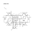
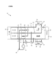
- FIG. 1 is a diagram showing a schematic configuration of the air conditioner 11 of the first embodiment.
- the air-conditioning device 11 is a vehicle in which components for air-conditioning, including a heat medium circuit through which a heat medium circulates, are housed in a housing 11a and unified. It is installed indoors. For example, by attaching each air conditioner 11 to each seat, individual air conditioning can be performed for each seat.
- the housing 11a constituting the air conditioner 11 is composed of a cold air flow path 12 and a hot air flow path 13 by a partition wall 11b.
- the cold air flow path 12 and the hot air flow path 13 each have a duct structure.
- the upstream side of the cold air flow path 12 communicates with the inside air introduction path 21 that introduces the inside air from the vehicle interior and the outside air introduction path 22 that introduces the outside air from the outside of the vehicle interior, and is provided with a switching damper 23.
- the switching damper 23 is rotatable between a position where the cold air flow path 12 communicates with the inside air introduction path 21 and a position where the cold air flow path 12 communicates with the outside air introduction path 22.
- the downstream side of the cold air flow path 12 communicates with the supply flow path 24 for supplying air to the vehicle interior and the discharge flow path 25 for discharging air to the outside of the vehicle interior, and includes a switching damper 26.
- the switching damper 26 (flow path switching portion) is rotatable between a position where the cold air flow path 12 communicates with the supply flow path 24 and a position where the cold air flow path 12 communicates with the discharge flow path 25.
- the upstream side of the warm air flow path 13 communicates with the inside air introduction path 31 that introduces the inside air from the vehicle interior and the outside air introduction path 22 that introduces the outside air from the outside of the vehicle interior, and is provided with a switching damper 33.
- the upstream side of the inside air introduction path 31 merges with the upstream side of the inside air introduction path 21.
- the switching damper 33 is rotatable between a position where the warm air flow path 13 communicates with the inside air introduction path 31 and a position where the warm air flow path 13 communicates with the outside air introduction path 22.
- the downstream side of the warm air flow path 13 communicates with the supply flow path 34 for supplying air to the vehicle interior and the discharge flow path 25 for discharging air to the outside of the vehicle interior, and includes a switching damper 36.
- the downstream side of the supply flow path 34 joins the downstream side of the supply flow path 24.
- the switching damper 36 (flow path switching portion) is rotatable between a position where the warm air flow path 13 communicates with the supply flow path 34 and a position where the warm air flow path 13 communicates with the discharge flow path 25.
- the cold air flow path 12 is provided with a blower fan 27 and an evaporator 28 that constitutes a refrigeration cycle, which will be described in detail later.
- the blower fan 27 is provided on the upstream side of the cold air flow path 12, and when driven by the motor, sucks the outside air and the inside air and sends them to the downstream side.
- the evaporator 28 is provided on the downstream side of the blower fan 27, and as a heat absorber and a dehumidifier, heat is generated between the air passing around the fin and the low-temperature heat medium (refrigerant) passing through the tube. Make a replacement. That is, by evaporating and vaporizing the heat medium in the tube, the air around the fins is cooled, and dew condensation is generated on the surface of the fins to dehumidify.
- the warm air flow path 13 is provided with a blower fan 37 and a radiator 38 that constitutes a refrigeration cycle together with an evaporator 28.
- the blower fan 37 is provided on the upstream side of the warm air flow path 13, and when driven by the motor, sucks the outside air and the inside air and sends them to the downstream side.
- the radiator 38 is provided on the downstream side of the blower fan 37, and as a radiator, heat exchange between the air passing around the heat radiation fins and the high-temperature heat medium (heat medium) passing through the tube. To warm the air around the fins.
- the refrigeration cycle constituting the heat medium circuit is configured by connecting at least the compressor 41, the radiator 38, the expansion valve 42, and the evaporator 28 in a circular manner in order.
- the compressor 41 compresses a low-pressure heat medium that is a gas phase to increase the pressure to a high-pressure heat medium that is easily liquefied.
- a rotary compressor, a swash plate compressor, a scroll compressor and the like can be adopted.
- An engine or an electric motor can be used as the drive source.
- the expansion valve 42 atomizes a high-pressure heat medium that is a liquid phase and ejects the heat medium to reduce the pressure to a low-pressure heat medium that easily vaporizes.
- a temperature-type expansion valve, a capillary tube, an orifice, or the like is adopted. Can be done.
- the heat medium circuit 43 in the present invention includes a relief valve 44 and a three-way valve 45 (switching control valve).
- the relief valve 44 is provided, for example, in a flow path branched from between the compressor 41 and the radiator 38, and opens when the pressure of the heat medium circuit 43 reaches a predetermined set value.
- the relief valve may be opened by electrical control or may be opened by mechanical configuration.
- a solenoid valve for switching between three ports and two positions can be adopted. In this case, specifically, the position where the outlet of the relief valve 44 communicates with the downstream side of the evaporator 28 in the cold air flow path 12 and the outlet of the relief valve 44 on the downstream side of the radiator 38 in the warm air flow path 13. Switch to one of the positions to communicate with.
- the air conditioner 11 in the present embodiment includes a control device (not shown), and the control device provides the switching dampers 23, 33, 26, 36, the blower fans 27, 37, the compressor 41, and the expansion valve 42. , And the three-way valve 45 is driven and controlled.
- a fluorocarbon refrigerant such as R134a, HFO1234yf, R32, a hydrocarbon refrigerant such as isobutane, and a natural refrigerant such as CO2 can be used.
- FIG. 1 is a diagram showing a state of the air conditioner 11 at the time of cooling by indoor intake.
- the switching damper 23 communicates with the inside air introduction path 21 in a state where the upstream side of the cold air flow path 12 is cut off from the outside air introduction path 22, and the switching damper 26 communicates with the discharge flow path 25 on the downstream side of the cold air flow path 12. It communicates with the supply flow path 24 in a state of being cut off from the above.
- the switching damper 33 communicates with the outside air introduction path 22 in a state where the upstream side of the warm air flow path 13 is cut off from the inside air introduction path 31, and the switching damper 36 cuts off the downstream side of the warm air flow path 13 from the supply flow path 34.
- the high-temperature and high-pressure heat medium discharged from the compressor 41 flows into the radiator 38, is cooled, and dissipates heat.
- the heat medium cooled by heat dissipation is depressurized by the expansion valve 42 to a low pressure, evaporates and vaporizes in the evaporator 28, and exerts an endothermic action.
- the air introduced into the cold air flow path 12 is supplied to the vehicle interior cooled and dehumidified by the evaporator 28.
- the outside air flowing into the warm air flow path 13 from the outside of the vehicle interior exchanges heat with the radiator 38, and then is discharged to the outside of the vehicle interior.
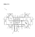
- FIG. 2 is a diagram showing a state of the air conditioner 11 at the time of cooling by outdoor intake air.
- the switching damper 23 communicates with the outside air introduction path 22 in a state where the upstream side of the cold air flow path 12 is cut off from the inside air introduction path 21, and the switching damper 33 communicates with the outside air introduction path 22 on the upstream side of the warm air flow path 13. It suffices to communicate with the inside air introduction path 31 in a state of being cut off from the inside air introduction path 31.
- the air introduced into the cold air flow path 12 from outside the vehicle interior is cooled and dehumidified by the evaporator 28 and supplied to the vehicle interior.
- the air introduced into the warm air flow path 13 from the vehicle interior exchanges heat with the radiator 38 and is discharged to the outside of the vehicle interior.
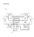
- FIG. 3 is a diagram showing a state of the air conditioner 11 during heating by indoor intake.
- the switching damper 23 communicates with the outside air introduction path 22 in a state where the upstream side of the cold air flow path 12 is cut off from the inside air introduction path 21, and the switching damper 26 connects the downstream side of the cold air flow path 12 to the supply flow path 24. It communicates with the discharge flow path 25 in a state of being cut off from the above.
- the switching damper 33 communicates with the inside air introduction path 31 in a state where the upstream side of the warm air flow path 13 is cut off from the outside air introduction path 22, and the switching damper 36 cuts off the downstream side of the warm air flow path 13 from the discharge flow path 25. In this state, it communicates with the supply flow path 34. Further, the three-way valve 45 communicates the outlet of the relief valve 44 to the downstream side of the evaporator 28 in the cold air flow path 12. Then, the blower fan 27, the blower fan 37, and the compressor 41 are driven.
- the air introduced into the warm air flow path 13 from the vehicle interior is heated by the radiator 38, and warm air is supplied to the vehicle interior. Further, the outside air flowing into the cold air flow path 12 from the outside of the vehicle interior exchanges heat with the evaporator 28 and is discharged to the outside of the vehicle interior.
- FIG. 4 is a diagram showing a state of the air conditioner 11 during heating by outdoor intake air.
- the switching damper 23 communicates with the inside air introduction path 21 in a state where the upstream side of the cold air flow path 12 is cut off from the outside air introduction path 22, and the switching damper 33 communicates with the inside air introduction path 31 on the upstream side of the warm air flow path 13. It suffices to communicate with the outside air introduction path 22 in a state of being cut off from the outside air.
- the outside air introduced into the warm air flow path 13 from the outside of the vehicle interior is heated by the radiator, and warm air is supplied to the interior of the vehicle.
- the air flowing into the cold air flow path 12 from the vehicle interior exchanges heat with the evaporator 28 and is discharged to the outside of the vehicle interior.
- the outlet of the relief valve 44 communicates with the discharge flow path 25 in both the cooling and heating cases.
- the switching damper 26 communicates with the supply flow path 24 in a state where the downstream side of the cold air flow path 12 is cut off from the discharge flow path 25.
- the switching damper 36 communicates with the discharge flow path 25 in a state where the downstream side of the warm air flow path 13 is cut off from the supply flow path 34.
- the three-way valve 45 communicates the outlet of the relief valve 44 to the downstream side of the radiator 38 in the warm air flow path 13. As a result, the outlet of the relief valve 44 can be communicated with the discharge flow path 25 during the cooling operation.
- the switching damper 26 communicates with the discharge flow path 25 in a state where the downstream side of the cold air flow path 12 is cut off from the supply flow path 24. Further, the switching damper 36 communicates with the supply flow path 34 in a state where the downstream side of the warm air flow path 13 is cut off from the discharge flow path 25. Further, the three-way valve 45 communicates the outlet of the relief valve 44 to the downstream side of the evaporator 28 in the cold air flow path 12. As a result, the outlet of the relief valve 44 can be communicated with the discharge flow path 25 during the heating operation.
- the inside of the heat medium circuit 43 becomes abnormally high pressure, and when the relief valve 44 operates, the heat medium is discharged to the discharge flow path 25 via the three-way valve 45. Therefore, even when the unitized air conditioner 11 is provided in the vehicle interior, the heat medium discharged by opening the relief valve 44 is not supplied to the user and is transmitted to the outside of the vehicle interior. Since it is discharged to the outside of the vehicle interior via the road 25, safety can be improved.
- the outlet of the relief valve 44 can be easily communicated with the discharge flow path 25 only by driving and controlling the switching damper 26, the switching damper 36, and the three-way valve 45.
- the air conditioner 11 since the air conditioner 11 is mounted in the vehicle interior of the automobile, the comfort in the vehicle interior can be improved.
- the discharge flow path 25 communicates with the outside of the vehicle interior, it is possible to prevent the high-temperature and high-pressure heat medium and oil from being discharged into the vehicle interior, and improve safety.
- the solenoid valve is used as the three-way valve 45, but the present invention is not limited to this, and for example, a rotary valve may be used.
- a two-way valve that can be opened and closed is provided in each of the flow path communicating with the cold air flow path 12 and the flow path communicating with the hot air flow path 13, and when one is opened, the other is closed, and when one is closed, the other is closed. You may try to open.
- a lid-shaped valve body that can be opened and closed is provided at the end of the flow path communicating with the cold air flow path 12 and the end of the flow path communicating with the hot air flow path 13, and when one is opened, the other is opened. You may close and open the other when you close one. That is, if the outlet of the relief valve 44 can be communicated with the cold air flow path 12 or the outlet of the relief valve 44 can be communicated with the hot air flow path 13, any switching control valve is used. be able to.
- the outlet of the relief valve 44 is communicated with the downstream side of the cold air flow path 12 or the downstream side of the hot air flow path 13, but the present invention is not limited to this.
- the outlet of the relief valve 44 may be directly communicated with the discharge flow path 25.
- FIG. 5 is a diagram showing a modified example in which the outlet of the relief valve is communicated with the discharge flow path.
- the outlet of the relief valve 44 is directly communicated with the discharge flow path 25, the same action and effect as those of the above-described embodiment can be obtained while omitting the driving process of the three-way valve 45 and the three-way valve. ..
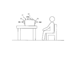
- FIG. 6 is a diagram showing an example of using the air conditioner according to the second embodiment.
- the air conditioner 51 is a portable air conditioner that can be carried by the user, and includes an introduction port 52, a supply port 53, and an discharge port 54.
- the introduction port 52 introduces outside air.
- the supply port 53 supplies cold air to the user during cooling and hot air during heating.
- the discharge port 54 faces at least a direction different from that of the supply port 53, and discharges hot air during cooling and cold air during heating. Therefore, when the air conditioner 51 is used, the supply port 53 is arranged on the user side, and the discharge port 54 is arranged on the side other than the user side.
- An exhaust duct can be separately attached to the exhaust port 54 to keep the exhaust away from the user.
- FIG. 7 is a diagram showing an air conditioner according to the second embodiment.
- the air conditioner 51 the above-mentioned inside air introduction path 21, outside air introduction path 22, switching damper 23, inside air introduction path 31, and switching damper 33 are omitted, and an introduction port 52, a supply port 53, and an discharge port 54 are added. ing.
- Other configurations are the same as those in the first embodiment described above, and detailed description of common parts will be omitted.
- the air conditioner 51 is housed in a housing (not shown), and the housing is provided with, for example, a handle or casters so that the air conditioner 51 can be easily carried.
- the upstream side of the cold air flow path 12 communicates with the introduction port 52.
- the downstream side of the cold air flow path 12 communicates with the supply port 53 and the discharge port 54.
- the switching damper 26 (flow path switching portion) is rotatable between a position where the cold air flow path 12 communicates with the supply port 53 and a position where the cold air flow path 12 communicates with the discharge port 54.
- the upstream side of the warm air flow path 13 communicates with the introduction port 52.
- the downstream side of the warm air flow path 13 communicates with the supply port 53 and the discharge port 54.
- the supply port 53 of the hot air flow path 13 is common to the supply port 53 of the cold air flow path 12.
- the switching damper 36 (flow path switching portion) is rotatable between a position where the warm air flow path 13 communicates with the supply port 53 and a position where the warm air flow path 13 communicates with the discharge port 54.
- FIG. 7 is a diagram showing an air conditioner during cooling.
- the switching damper 26 communicates with the supply port 53 in a state where the downstream side of the cold air flow path 12 is blocked from the discharge port 54.
- the switching damper 36 communicates with the discharge port 54 in a state where the downstream side of the warm air flow path 13 is cut off from the supply port 53.
- the three-way valve 45 communicates the outlet of the relief valve 44 to the downstream side of the radiator 38 in the warm air flow path 13. Then, the blower fan 27, the blower fan 37, and the compressor 41 are driven.
- FIG. 8 is a diagram showing an air conditioner during heating.
- the switching damper 26 communicates with the discharge port 54 in a state where the downstream side of the cold air flow path 12 is cut off from the supply port 53.
- the switching damper 36 communicates with the supply port 53 in a state where the downstream side of the warm air flow path 13 is blocked from the discharge port 54.
- the three-way valve 45 communicates the outlet of the relief valve 44 to the downstream side of the evaporator 28 in the cold air flow path 12. Then, the blower fan 27, the blower fan 37, and the compressor 41 are driven.
- the air conditioner 51 is a portable air conditioner, and the discharge port 54 is configured to face a direction different from that of the supply port 53. Therefore, even if the relief valve 44 is activated, the heat medium is not discharged toward the user, and safety can be improved. Other effects are the same as those in the first embodiment described above.
Landscapes
- Engineering & Computer Science (AREA)
- Mechanical Engineering (AREA)
- Physics & Mathematics (AREA)
- Thermal Sciences (AREA)
- General Engineering & Computer Science (AREA)
- Chemical & Material Sciences (AREA)
- Combustion & Propulsion (AREA)
- Air-Conditioning For Vehicles (AREA)
Abstract
ユニット化された空気調和装置を車室内に設けた構成において、圧力制御弁が開いた場合であっても、高温高圧の熱媒体がユーザに吐出されることなく、安全に用いることができる空気調和装置を提供する。熱媒体との熱交換により、冷房時には温風を排出し、暖房時には冷風を排出する排出流路を備える。リリーフ弁が作動したときに、熱媒体は排出流路により支障なく排出することができる。
Description
本発明は、熱媒体が循環する熱媒体回路を有し、被空調空気の調整を行う空気調和装置に関するものである。
一般に、空気調和装置は、熱媒体としての冷媒が循環する冷凍サイクルを備え、この冷凍サイクルを構成する蒸発器や放熱器と熱交換することにより、被空調空気の温度調整を行う。例えば、車両等に搭載される空気調和装置として、特許文献1を挙げることができる。特許文献1は、車両が外部から受ける衝撃によって、冷凍サイクル中に圧縮された冷媒が、狭い車室内に漏洩する不都合を抑制するため、車両の衝撃を検出したときに、熱媒体循環路に大気開放可能な電磁弁を設けている。
一方で、圧縮機、放熱器、膨張弁、蒸発器等、熱媒体回路を構成する全てのコンポーネントを一つにユニット化し、それを車室内の例えば各シートに取付けることで、シートごとに個別空調を行なう空気調和装置の開発が行われている。この場合、熱媒体回路内の異常圧力が発生した場合に、この熱媒体回路を保護するために、所定圧力以上で開くリリーフ弁を設ける必要がある。しかし、ユニット化された空気調和装置を車室内に設けた構成では、リリーフ弁が開いたときに高温高圧の熱媒体が結果として車室内に排出されてしまう問題がある。そこで、本発明の課題は、リリーフ弁が開くときの安全性を向上させることである。
本発明の一態様に係る空気調和装置は、熱媒体が循環する熱媒体回路を含む空気調和を行なう各構成要素をユニット化して構成した空気調和装置において、熱媒体との熱交換により、冷房時には温風を排出し、暖房時には冷風を排出する排出流路と、排出口が排出流路に連通され、熱媒体回路の圧力が予め定めた設定値に達したときに、内部の熱媒体を排出するリリーフ弁と、を備える。
本発明によれば、リリーフ弁が作動したときに熱媒体が排出流路に排出される。排出流路は、ユーザに供給されることなく排出される流路であるため、安全性を向上させることができる。
以下、本発明の実施形態を図面に基づいて説明する。なお、各図面は模式的なものであって、現実のものとは異なる場合がある。また、以下の実施形態は、本発明の技術的思想を具体化するための装置や方法を例示するものであり、構成を下記のものに限定するものでない。すなわち、本発明の技術的思想は、特許請求の範囲に記載された技術的範囲内において、種々の変更を加えることができる。
《第1実施形態》
《構成》
図1は、第1実施形態の空気調和装置11の概略構成を示す図である。本実施の形態にかかる空気調和装置11は、熱媒体が循環する熱媒体回路を含め、空気調和を行なう構成要素が筐体11a内に収容して単一化されたものであり、車両の車室内に搭載される。例えば、各空気調和装置11を各シートに取り付けることで、シートごとに個別空調を行なうことができる。空気調和装置11を構成する筐体11aは、仕切壁11bによって冷風流路12と、温風流路13とが構成されている。冷風流路12及び温風流路13は、夫々、ダクト構造である。
《構成》
図1は、第1実施形態の空気調和装置11の概略構成を示す図である。本実施の形態にかかる空気調和装置11は、熱媒体が循環する熱媒体回路を含め、空気調和を行なう構成要素が筐体11a内に収容して単一化されたものであり、車両の車室内に搭載される。例えば、各空気調和装置11を各シートに取り付けることで、シートごとに個別空調を行なうことができる。空気調和装置11を構成する筐体11aは、仕切壁11bによって冷風流路12と、温風流路13とが構成されている。冷風流路12及び温風流路13は、夫々、ダクト構造である。
冷風流路12の上流側は、車室内から内気を導入する内気導入路21、及び車室外から外気を導入する外気導入路22と連通しており、切替ダンパ23を備える。切換ダンパ23は、冷風流路12を内気導入路21と連通させる位置と、冷風流路12を外気導入路22と連通させる位置と、の間で回動可能である。冷風流路12の下流側は、車室内へ空気を供給する供給流路24、及び車室外へ空気を排出する排出流路25と連通しており、切替ダンパ26を備える。切換ダンパ26(流路切換部)は、冷風流路12を供給流路24と連通させる位置と、冷風流路12を排出流路25と連通させる位置と、の間で回動可能である。
温風流路13の上流側は、車室内から内気を導入する内気導入路31、及び車室外から外気を導入する外気導入路22と連通しており、切替ダンパ33を備える。内気導入路31の上流側は、内気導入路21の上流側と合流している。切換ダンパ33は、温風流路13を内気導入路31と連通させる位置と、温風流路13を外気導入路22と連通させる位置と、の間で回動可能である。温風流路13の下流側は、車室内へ空気を供給する供給流路34、及び車室外へ空気を排出する排出流路25と連通しており、切替ダンパ36を備える。供給流路34の下流側は、供給流路24の下流側と合流している。切換ダンパ36(流路切換部)は、温風流路13を供給流路34と連通させる位置と、温風流路13を排出流路25と連通させる位置と、の間で回動可能である。
冷風流路12には、送風ファン27と、詳細は後述する冷凍サイクルを構成する蒸発器28と、が設けられている。送風ファン27は、冷風流路12の上流側に設けられており、モータによって駆動されるときに、外気や内気を吸引し、下流側へと送る。蒸発器28は、送風ファン27よりも下流側に設けられており、吸熱器及び除湿器として、フィンの周囲を通過する空気とチューブ内を通過する低温の熱媒体(冷媒)との間で熱交換を行なう。すなわち、チューブ内の熱媒体を蒸発気化させることで、フィンの周囲の空気を冷却すると共に、フィンの表面に結露を生じさせて除湿を行なう。
温風流路13には、送風ファン37と、蒸発器28とともに冷凍サイクルを構成する放熱器38と、が設けられている。送風ファン37は、温風流路13の上流側に設けられており、モータによって駆動されるときに、外気や内気を吸引し、下流側へと送る。放熱器38は、送風ファン37よりも下流側に設けられており、放熱器として、放熱フィンの周囲を通過する空気とチューブ内を通過する高温の熱媒体(熱媒)との間で熱交換を行なうことで、フィンの周囲の空気を加温する。
次に、本発明における熱媒体回路を構成する冷凍サイクルについて説明する。熱媒体回路を構成する冷凍サイクルは、少なくとも、圧縮機41と、放熱器38と、膨張弁42と、蒸発器28を順次環状に接続して構成される。圧縮機41は、気相である低圧の熱媒体を圧縮することにより、液化しやすい高圧の熱媒体に昇圧させるものである。例えば、ロータリ圧縮機、斜板式圧縮機、スクロール圧縮機等を採用することができる。駆動源としてはエンジンや電動モータを用いることができる。膨張弁42は、液相である高圧の熱媒体を霧状にして噴き出すことにより、気化しやすい低圧の熱媒体に減圧するものであり、温度式膨張弁、キャピラリーチューブ、オリフィス等を採用することができる。
本発明における熱媒体回路43は、リリーフ弁44と、三方弁45(切換制御弁)と、を備える。リリーフ弁44は、例えば、圧縮機41と放熱器38との間から分岐した流路に設けられ、熱媒体回路43の圧力が予め定めた設定値に達したときに開弁する。リリーフ弁は、電気的制御により開弁してもよく、機械的構成により開弁してもよい。三方弁45は、例えば3ポート2位置切換のソレノイドバルブを採用することができる。この場合、具体的には、リリーフ弁44の出口を冷風流路12における蒸発器28よりも下流側に連通させる位置と、リリーフ弁44の出口を温風流路13における放熱器38よりも下流側に連通させる位置と、の何れか一方に切り換える。
本実施の形態における空気調和装置11は、図示しない制御装置を備えており、当該制御装置により、各切換ダンパ23、33、26、36、各送風ファン27、37、圧縮機41、膨張弁42、及び三方弁45が駆動制御される。
本発明における熱媒体回路を構成する冷凍サイクルに用いる熱媒体としては、R134a、HFO1234yf、R32等のフロン系冷媒や、イソブタン等の炭化水素系冷媒、CO2等の自然冷媒を用いることができる。
次に、各運転モードについて説明する。以下、室内吸気による冷房時、室外吸気による冷房時と、室内吸気による暖房、室外吸気による暖房時について説明する。
[冷房運転]
図1は、空気調和装置11の室内吸気による冷房時の状態を示す図である。この冷房運転では、切換ダンパ23が冷風流路12の上流側を外気導入路22から遮断した状態で内気導入路21に連通させ、切換ダンパ26が冷風流路12の下流側を排出流路25から遮断した状態で供給流路24に連通させる。また、切換ダンパ33が温風流路13の上流側を内気導入路31から遮断した状態で外気導入路22に連通させ、切換ダンパ36が温風流路13の下流側を供給流路34から遮断した状態で排出流路25に連通させる。また、三方弁45は、リリーフ弁44の出口を温風流路13における放熱器38よりも下流側に連通させる。そして、送風ファン27、送風ファン37、及び圧縮機41を駆動する。
図1は、空気調和装置11の室内吸気による冷房時の状態を示す図である。この冷房運転では、切換ダンパ23が冷風流路12の上流側を外気導入路22から遮断した状態で内気導入路21に連通させ、切換ダンパ26が冷風流路12の下流側を排出流路25から遮断した状態で供給流路24に連通させる。また、切換ダンパ33が温風流路13の上流側を内気導入路31から遮断した状態で外気導入路22に連通させ、切換ダンパ36が温風流路13の下流側を供給流路34から遮断した状態で排出流路25に連通させる。また、三方弁45は、リリーフ弁44の出口を温風流路13における放熱器38よりも下流側に連通させる。そして、送風ファン27、送風ファン37、及び圧縮機41を駆動する。
これにより、圧縮機41から吐出した高温高圧の熱媒体は、放熱器38内に流入して冷却され、放熱する。放熱により冷却された熱媒体は、膨張弁42において減圧され低圧となり、蒸発器28において蒸発気化し、吸熱作用を発揮する。これにより、冷風流路12内に導入された空気は蒸発器28で冷却及び除湿された車室内に供給される。また、車室外から温風流路13内に流入した外気は、放熱器38と熱交換した後、車室外に排出される。
図2は、空気調和装置11の室外吸気による冷房時の状態を示す図である。室外吸気の場合、切換ダンパ23が冷風流路12の上流側を内気導入路21から遮断した状態で外気導入路22に連通させ、切換ダンパ33が温風流路13の上流側を外気導入路22から遮断した状態で内気導入路31に連通させればよい。これにより、車室外から冷風流路12内に導入された空気は、蒸発器28で冷却及び除湿され車室内に供給される。そして、車室内から温風流路13内に導入された空気は、放熱器38と熱交換した後、車室外に排出される。
[暖房運転]
次に、暖房運転について説明する。図3は、空気調和装置11の室内吸気による暖房時の状態を示す図である。この暖房運転では、切換ダンパ23が冷風流路12の上流側を内気導入路21から遮断した状態で外気導入路22に連通させ、切換ダンパ26が冷風流路12の下流側を供給流路24から遮断した状態で排出流路25に連通させる。また、切換ダンパ33が温風流路13の上流側を外気導入路22から遮断した状態で内気導入路31に連通させ、切換ダンパ36が温風流路13の下流側を排出流路25から遮断した状態で供給流路34に連通させる。また、三方弁45は、リリーフ弁44の出口を冷風流路12における蒸発器28よりも下流側に連通させる。そして、送風ファン27、送風ファン37、及び圧縮機41を駆動する。
次に、暖房運転について説明する。図3は、空気調和装置11の室内吸気による暖房時の状態を示す図である。この暖房運転では、切換ダンパ23が冷風流路12の上流側を内気導入路21から遮断した状態で外気導入路22に連通させ、切換ダンパ26が冷風流路12の下流側を供給流路24から遮断した状態で排出流路25に連通させる。また、切換ダンパ33が温風流路13の上流側を外気導入路22から遮断した状態で内気導入路31に連通させ、切換ダンパ36が温風流路13の下流側を排出流路25から遮断した状態で供給流路34に連通させる。また、三方弁45は、リリーフ弁44の出口を冷風流路12における蒸発器28よりも下流側に連通させる。そして、送風ファン27、送風ファン37、及び圧縮機41を駆動する。
これにより、車室内から温風流路13内に導入された空気は、放熱器38で加温され、温かい空気が車室内に供給される。また、車室外から冷風流路12内に流入した外気は、蒸発器28と熱交換した後、車室外に排出される。
図4は、空気調和装置11の室外吸気による暖房時の状態を示す図である。室外吸気の場合、切換ダンパ23が冷風流路12の上流側を外気導入路22から遮断した状態で内気導入路21に連通させ、切換ダンパ33が温風流路13の上流側を内気導入路31から遮断した状態で外気導入路22に連通させればよい。これにより、車室外から温風流路13内に導入された外気は、放熱器で加温され、暖かい空気が車室内に供給される。また、車室内から冷風流路12内に流入した空気は、蒸発器28と熱交換した後、車室外に排出される。
《作用》
次に、第1実施形態の主要な作用効果について説明する。上述したように、各冷房時、暖房時のいずれの場合においても、リリーフ弁44の出口は、排出流路25に連通させている。具体的に、冷房運転では、切換ダンパ26が冷風流路12の下流側を排出流路25から遮断した状態で供給流路24に連通させる。また、切換ダンパ36が温風流路13の下流側を供給流路34から遮断した状態で排出流路25に連通させる。また、三方弁45がリリーフ弁44の出口を温風流路13における放熱器38よりも下流側に連通させる。これにより、冷房運転時にリリーフ弁44の出口を排出流路25に連通させることができる。
次に、第1実施形態の主要な作用効果について説明する。上述したように、各冷房時、暖房時のいずれの場合においても、リリーフ弁44の出口は、排出流路25に連通させている。具体的に、冷房運転では、切換ダンパ26が冷風流路12の下流側を排出流路25から遮断した状態で供給流路24に連通させる。また、切換ダンパ36が温風流路13の下流側を供給流路34から遮断した状態で排出流路25に連通させる。また、三方弁45がリリーフ弁44の出口を温風流路13における放熱器38よりも下流側に連通させる。これにより、冷房運転時にリリーフ弁44の出口を排出流路25に連通させることができる。
一方、暖房運転では、切換ダンパ26が冷風流路12の下流側を供給流路24から遮断した状態で排出流路25に連通させる。また、切換ダンパ36が温風流路13の下流側を排出流路25から遮断した状態で供給流路34に連通させる。また、三方弁45がリリーフ弁44の出口を冷風流路12における蒸発器28よりも下流側に連通させる。これにより、暖房運転時にリリーフ弁44の出口を排出流路25に連通させることができる。
これにより、熱媒体回路43内が異常高圧になり、リリーフ弁44が作動すると、熱媒体は三方弁45を介して排出流路25に排出される。そのため、ユニット化された空気調和装置11を車室内に設けた場合であっても、リリーフ弁44の開放により排出された熱媒体は、ユーザに供給されることなく、車室外に連通した排出流路25を介して車室外に排出されるため、安全性を向上させることができる。
このように、本実施の形態では、切換ダンパ26、切換ダンパ36、及び三方弁45を駆動制御するだけで、リリーフ弁44の出口を容易に排出流路25に連通させることができる。特に、本実施の形態では、空気調和装置11は、自動車の車室内に搭載されるため、車室内の快適性を向上させることができる。また、排出流路25は、車室外に連通しているため、高温高圧の熱媒体やオイルが車室内に排出されることを防止し、安全性を向上させることができる。
《変形例》
本実施形態では、三方弁45としてソレノイドバルブを使用しているが、これに限定されるものではなく、例えばロータリ弁を使用してもよい。また、冷風流路12に連通する流路、及び温風流路13に連通する流路に、夫々、開閉可能な二方弁を設け、一方を開くときに他方を閉じ、一方を閉じるときに他方を開くようにしてもよい。さらに、冷風流路12に連通する流路の端部、及び温風流路13に連通する流路の端部に、夫々、開閉可能な蓋状の弁体を設け、一方を開くときに他方を閉じ、一方を閉じるときに他方を開くようにしてもよい。すなわち、リリーフ弁44の出口を冷風流路12に連通させるか、又はリリーフ弁44の出口を温風流路13に連通させるかの何れか一方に切り換えることができれば、任意の切換制御弁を使用することができる。
本実施形態では、三方弁45としてソレノイドバルブを使用しているが、これに限定されるものではなく、例えばロータリ弁を使用してもよい。また、冷風流路12に連通する流路、及び温風流路13に連通する流路に、夫々、開閉可能な二方弁を設け、一方を開くときに他方を閉じ、一方を閉じるときに他方を開くようにしてもよい。さらに、冷風流路12に連通する流路の端部、及び温風流路13に連通する流路の端部に、夫々、開閉可能な蓋状の弁体を設け、一方を開くときに他方を閉じ、一方を閉じるときに他方を開くようにしてもよい。すなわち、リリーフ弁44の出口を冷風流路12に連通させるか、又はリリーフ弁44の出口を温風流路13に連通させるかの何れか一方に切り換えることができれば、任意の切換制御弁を使用することができる。
本実施形態では、リリーフ弁44の出口を冷風流路12の下流側、又は温風流路13の下流側に連通させているが、これに限定されるものではない。例えば、リリーフ弁44の出口を排出流路25に直接連通させてもよい。
図5は、リリーフ弁の出口を排出流路に連通させた変形例を示す図である。このように、リリーフ弁44の出口を排出流路25に直接連通させれば、三方弁45や三方弁の駆動処理を省略しつつも、前述した実施形態と同様の作用効果を得ることができる。
《第2実施形態》
《構成》
第2実施形態は、ユーザによって持ち運びが可能な移動式のポータブルエアコンに適用したものである。図6は、第2実施形態における空気調和装置の使用例を示す図である。空気調和装置51は、ユーザによって持ち運びが可能なポータブルエアコンであり、導入口52、供給口53、及び排出口54を備える。導入口52は外気を導入する。供給口53は、冷房時には冷風を、暖房時には温風をユーザに供給する。排出口54は、少なくとも供給口53とは異なる方向を向いており、冷房時には温風を、暖房時には冷風を排出する。したがって、空気調和装置51を使用する際には、供給口53がユーザ側に配置され、排出口54がユーザ側以外に配置されるようにして使用する。排出口54には、別途、排気ダクトを取り付け、ユーザから排気を遠ざけることもできる。
《構成》
第2実施形態は、ユーザによって持ち運びが可能な移動式のポータブルエアコンに適用したものである。図6は、第2実施形態における空気調和装置の使用例を示す図である。空気調和装置51は、ユーザによって持ち運びが可能なポータブルエアコンであり、導入口52、供給口53、及び排出口54を備える。導入口52は外気を導入する。供給口53は、冷房時には冷風を、暖房時には温風をユーザに供給する。排出口54は、少なくとも供給口53とは異なる方向を向いており、冷房時には温風を、暖房時には冷風を排出する。したがって、空気調和装置51を使用する際には、供給口53がユーザ側に配置され、排出口54がユーザ側以外に配置されるようにして使用する。排出口54には、別途、排気ダクトを取り付け、ユーザから排気を遠ざけることもできる。
図7は、第2実施形態の空気調和装置を示す図である。空気調和装置51では、前述した内気導入路21、外気導入路22、切換ダンパ23、内気導入路31、及び切換ダンパ33が省略され、導入口52、供給口53、及び排出口54が追加されている。その他の構成については、前述した第1実施形態と同様であり、共通する部分については詳細な説明を省略する。なお、空気調和装置51は、図示しない筐体に収められており、持ち運びが容易となるように、筐体には例えば把手やキャスタが設けられているものとする。
冷風流路12の上流側は、導入口52に連通している。冷風流路12の下流側は、供給口53、及び排出口54に連通している。切換ダンパ26(流路切換部)は、冷風流路12を供給口53に連通させる位置と、冷風流路12を排出口54に連通させる位置と、の間で回動可能である。温風流路13の上流側は、導入口52に連通している。温風流路13の下流側は、供給口53、及び排出口54に連通している。温風流路13の供給口53は、冷風流路12の供給口53と共通である。切換ダンパ36(流路切換部)は、温風流路13を供給口53に連通させる位置と、温風流路13を排出口54に連通させる位置と、の間で回動可能である。
次に、各運転モードについて説明する。
[冷房運転]
図7は、冷房時の空気調和装置を示す図である。ここでは、切換ダンパ26が冷風流路12の下流側を排出口54から遮断した状態で供給口53に連通させる。また、切換ダンパ36が温風流路13の下流側を供給口53から遮断した状態で排出口54に連通させる。また、三方弁45は、リリーフ弁44の出口を温風流路13における放熱器38よりも下流側に連通させる。そして、送風ファン27、送風ファン37、及び圧縮機41を駆動する。
図7は、冷房時の空気調和装置を示す図である。ここでは、切換ダンパ26が冷風流路12の下流側を排出口54から遮断した状態で供給口53に連通させる。また、切換ダンパ36が温風流路13の下流側を供給口53から遮断した状態で排出口54に連通させる。また、三方弁45は、リリーフ弁44の出口を温風流路13における放熱器38よりも下流側に連通させる。そして、送風ファン27、送風ファン37、及び圧縮機41を駆動する。
[暖房運転]
図8は、暖房時の空気調和装置を示す図である。ここでは、切換ダンパ26が冷風流路12の下流側を供給口53から遮断した状態で排出口54に連通させる。また、切換ダンパ36が温風流路13の下流側を排出口54から遮断した状態で供給口53に連通させる。また、三方弁45は、リリーフ弁44の出口を冷風流路12における蒸発器28よりも下流側に連通させる。そして、送風ファン27、送風ファン37、及び圧縮機41を駆動する。
図8は、暖房時の空気調和装置を示す図である。ここでは、切換ダンパ26が冷風流路12の下流側を供給口53から遮断した状態で排出口54に連通させる。また、切換ダンパ36が温風流路13の下流側を排出口54から遮断した状態で供給口53に連通させる。また、三方弁45は、リリーフ弁44の出口を冷風流路12における蒸発器28よりも下流側に連通させる。そして、送風ファン27、送風ファン37、及び圧縮機41を駆動する。
《作用》
次に、第2実施形態の主要な作用効果について説明する。空気調和装置51は、ポータブルエアコンであり、排出口54は、供給口53とは異なる方向を向いて構成される。したがって、リリーフ弁44が作動したとしても、熱媒体がユーザに向かって排出されることはなく、安全性を向上させることができる。その他の作用効果は、前述した第1実施形態と同様である。
次に、第2実施形態の主要な作用効果について説明する。空気調和装置51は、ポータブルエアコンであり、排出口54は、供給口53とは異なる方向を向いて構成される。したがって、リリーフ弁44が作動したとしても、熱媒体がユーザに向かって排出されることはなく、安全性を向上させることができる。その他の作用効果は、前述した第1実施形態と同様である。
以上、限られた数の実施形態を参照しながら説明したが、権利範囲はそれらに限定されるものではなく、上記の開示に基づく実施形態の改変は、当業者にとって自明のことである。
11…空気調和装置、11a…筐体、11b…仕切壁、12…冷風流路、13…温風流路、21…内気導入路、22…外気導入路、23…切換ダンパ、24…供給流路、25…排出流路、26…切換ダンパ、27…送風ファン、28…蒸発器、31…内気導入路、33…切換ダンパ、34…供給流路、36…切換ダンパ、37…送風ファン、38…放熱器、41…圧縮機、42…膨張弁、43…熱媒体回路、44…リリーフ弁、45…三方弁、51…空気調和装置、52…導入口、53…供給口、54…排出口
Claims (7)
- 熱媒体が循環する熱媒体回路を含む空気調和を行なう各構成要素をユニット化して構成した空気調和装置において、
前記熱媒体との熱交換により、冷房時には温風を排出し、暖房時には冷風を排出する排出流路と、
排出口が前記排出流路に連通され、前記熱媒体回路の圧力が予め定めた設定値に達したときに、内部の前記熱媒体を排出するリリーフ弁と、を備えることを特徴とする空気調和装置。 - 前記熱媒体回路は、少なくとも圧縮機、放熱器、膨張機構、蒸発器を含むことを特徴とする請求項1に記載の空気調和装置。
- 前記蒸発器との熱交換によって冷風が流れる冷風流路と、
前記放熱器との熱交換によって温風が流れる温風流路と、
冷房時に前記排出流路を前記冷風流路から遮断した状態で前記温風流路に連通させ、暖房時に前記排出流路を前記温風流路から遮断した状態で前記冷風流路に連通させる流路切換部と、
冷房時に前記リリーフ弁の排出口を前記冷風流路から遮断した状態で前記温風流路に連通させ、暖房時に前記リリーフ弁の排出口を前記温風流路から遮断した状態で前記冷風流路に連通させる切換制御弁と、を備えることを特徴とする請求項2に記載の空気調和装置。 - 車両の車室内に搭載することを特徴とする請求項1~3の何れか一項に記載の空気調和装置。
- 前記排出流路は、車室外に連通していることを特徴とする請求項4に記載の空気調和装置。
- ユーザによって持ち運びが可能であることを特徴とする請求項1~3の何れか一項に記載の空気調和装置。
- 前記熱媒体との熱交換により、暖房時に温風をユーザに供給し、冷房時に冷風をユーザに供給する供給流路を備え、
前記排出流路の排出口は、前記供給流路の供給口とは異なる方向を向いていることを特徴とする請求項6に記載の空気調和装置。
Priority Applications (1)
| Application Number | Priority Date | Filing Date | Title |
|---|---|---|---|
| CN202080020190.7A CN113557398A (zh) | 2019-03-19 | 2020-03-12 | 空调装置 |
Applications Claiming Priority (2)
| Application Number | Priority Date | Filing Date | Title |
|---|---|---|---|
| JP2019-051331 | 2019-03-19 | ||
| JP2019051331A JP2020153557A (ja) | 2019-03-19 | 2019-03-19 | 空気調和装置 |
Publications (1)
| Publication Number | Publication Date |
|---|---|
| WO2020189489A1 true WO2020189489A1 (ja) | 2020-09-24 |
Family
ID=72519833
Family Applications (1)
| Application Number | Title | Priority Date | Filing Date |
|---|---|---|---|
| PCT/JP2020/010779 Ceased WO2020189489A1 (ja) | 2019-03-19 | 2020-03-12 | 空気調和装置 |
Country Status (3)
| Country | Link |
|---|---|
| JP (1) | JP2020153557A (ja) |
| CN (1) | CN113557398A (ja) |
| WO (1) | WO2020189489A1 (ja) |
Cited By (1)
| Publication number | Priority date | Publication date | Assignee | Title |
|---|---|---|---|---|
| WO2026030381A1 (en) * | 2024-08-02 | 2026-02-05 | Bergstrom, Inc. | Air-reversible heating, ventilation, and air conditioning system with ventilation |
Families Citing this family (3)
| Publication number | Priority date | Publication date | Assignee | Title |
|---|---|---|---|---|
| JP7197815B1 (ja) | 2021-09-30 | 2022-12-28 | ダイキン工業株式会社 | 冷凍サイクル装置 |
| JP2023088652A (ja) * | 2021-12-15 | 2023-06-27 | サンデン株式会社 | ダクトシステム |
| US12023981B2 (en) | 2022-07-22 | 2024-07-02 | Hanon Systems | Quad zone booster intake LPM cooling assembly |
Citations (7)
| Publication number | Priority date | Publication date | Assignee | Title |
|---|---|---|---|---|
| JPH1123115A (ja) * | 1997-06-30 | 1999-01-26 | Denso Corp | 冷凍サイクル |
| JP2007218459A (ja) * | 2006-02-15 | 2007-08-30 | Matsushita Electric Ind Co Ltd | 冷凍サイクル装置および保冷庫 |
| JP2014020675A (ja) * | 2012-07-18 | 2014-02-03 | Denso Corp | 電池温調用冷凍サイクル装置 |
| WO2015140876A1 (ja) * | 2014-03-17 | 2015-09-24 | 三菱電機株式会社 | 冷凍サイクル装置 |
| JP2016145015A (ja) * | 2015-02-09 | 2016-08-12 | 株式会社デンソー | シート空調装置 |
| JP2019038355A (ja) * | 2017-08-24 | 2019-03-14 | 株式会社デンソー | 車両用空調システム |
| JP2019107969A (ja) * | 2017-12-18 | 2019-07-04 | 株式会社デンソー | 車両用空調装置 |
Family Cites Families (8)
| Publication number | Priority date | Publication date | Assignee | Title |
|---|---|---|---|---|
| JPH10175426A (ja) * | 1996-12-17 | 1998-06-30 | Toyota Motor Corp | 車両用空調装置 |
| JP3355548B2 (ja) * | 1998-09-03 | 2002-12-09 | 株式会社デンソー | 車両用冷凍装置 |
| JP2004351985A (ja) * | 2003-05-27 | 2004-12-16 | Sanden Corp | 車両用空調装置 |
| JP2006145075A (ja) * | 2004-11-17 | 2006-06-08 | Sanden Corp | 車両用空調装置 |
| CN103717454B (zh) * | 2011-08-17 | 2016-11-16 | 株式会社日立制作所 | 车辆用设备温度调节系统 |
| WO2016017939A1 (ko) * | 2014-07-31 | 2016-02-04 | 한온시스템 주식회사 | 차량용 히트 펌프 시스템 |
| US10449825B2 (en) * | 2015-05-11 | 2019-10-22 | Hanon Systems | Air conditioning system |
| EP3228486B1 (en) * | 2016-04-06 | 2020-05-06 | Lg Electronics Inc. | Safety device for vehicle |
-
2019
- 2019-03-19 JP JP2019051331A patent/JP2020153557A/ja active Pending
-
2020
- 2020-03-12 WO PCT/JP2020/010779 patent/WO2020189489A1/ja not_active Ceased
- 2020-03-12 CN CN202080020190.7A patent/CN113557398A/zh active Pending
Patent Citations (7)
| Publication number | Priority date | Publication date | Assignee | Title |
|---|---|---|---|---|
| JPH1123115A (ja) * | 1997-06-30 | 1999-01-26 | Denso Corp | 冷凍サイクル |
| JP2007218459A (ja) * | 2006-02-15 | 2007-08-30 | Matsushita Electric Ind Co Ltd | 冷凍サイクル装置および保冷庫 |
| JP2014020675A (ja) * | 2012-07-18 | 2014-02-03 | Denso Corp | 電池温調用冷凍サイクル装置 |
| WO2015140876A1 (ja) * | 2014-03-17 | 2015-09-24 | 三菱電機株式会社 | 冷凍サイクル装置 |
| JP2016145015A (ja) * | 2015-02-09 | 2016-08-12 | 株式会社デンソー | シート空調装置 |
| JP2019038355A (ja) * | 2017-08-24 | 2019-03-14 | 株式会社デンソー | 車両用空調システム |
| JP2019107969A (ja) * | 2017-12-18 | 2019-07-04 | 株式会社デンソー | 車両用空調装置 |
Cited By (1)
| Publication number | Priority date | Publication date | Assignee | Title |
|---|---|---|---|---|
| WO2026030381A1 (en) * | 2024-08-02 | 2026-02-05 | Bergstrom, Inc. | Air-reversible heating, ventilation, and air conditioning system with ventilation |
Also Published As
| Publication number | Publication date |
|---|---|
| CN113557398A (zh) | 2021-10-26 |
| JP2020153557A (ja) | 2020-09-24 |
Similar Documents
| Publication | Publication Date | Title |
|---|---|---|
| JP4505510B2 (ja) | 車両用空調システム | |
| US9346337B2 (en) | Air conditioning device for vehicle | |
| JP3799748B2 (ja) | 車両用空調装置 | |
| JP6590558B2 (ja) | 車両用空気調和装置 | |
| JP2020153557A (ja) | 空気調和装置 | |
| JP2020142789A (ja) | 熱管理システム | |
| JP5846094B2 (ja) | 冷凍サイクル装置 | |
| JP3563094B2 (ja) | 車両用空気調和装置 | |
| US20180147911A1 (en) | Air conditioning system | |
| KR20180113712A (ko) | 차량용 공조장치 | |
| JP7848659B2 (ja) | 車両の熱管理システム | |
| JPH09240266A (ja) | 冷暖房装置 | |
| JP6589242B2 (ja) | 車両用空調装置 | |
| JP2001260635A (ja) | 車両用空調装置 | |
| JP2024178706A (ja) | 車両空調システム | |
| WO2022163712A1 (ja) | 温度制御システム | |
| JP5379814B2 (ja) | 車両用空気調和装置 | |
| WO2020246306A1 (ja) | 車両用空気調和装置 | |
| JP2001030743A (ja) | 電気自動車用ヒートポンプ式空気調和装置 | |
| JP7097345B2 (ja) | 車両用空調装置 | |
| JP2004098974A (ja) | 車両用空調装置 | |
| WO2020241612A1 (ja) | 車両用空気調和装置 | |
| JPH0596931A (ja) | 車両用空調装置 | |
| JP4082192B2 (ja) | 空調装置 | |
| JPH07132728A (ja) | 自動車用空気調和装置 |
Legal Events
| Date | Code | Title | Description |
|---|---|---|---|
| 121 | Ep: the epo has been informed by wipo that ep was designated in this application |
Ref document number: 20773226 Country of ref document: EP Kind code of ref document: A1 |
|
| NENP | Non-entry into the national phase |
Ref country code: DE |
|
| 122 | Ep: pct application non-entry in european phase |
Ref document number: 20773226 Country of ref document: EP Kind code of ref document: A1 |