EP3228486B1 - Safety device for vehicle - Google Patents
Safety device for vehicle Download PDFInfo
- Publication number
- EP3228486B1 EP3228486B1 EP17000175.4A EP17000175A EP3228486B1 EP 3228486 B1 EP3228486 B1 EP 3228486B1 EP 17000175 A EP17000175 A EP 17000175A EP 3228486 B1 EP3228486 B1 EP 3228486B1
- Authority
- EP
- European Patent Office
- Prior art keywords
- vehicle
- valve
- unit
- control unit
- compressor
- Prior art date
- Legal status (The legal status is an assumption and is not a legal conclusion. Google has not performed a legal analysis and makes no representation as to the accuracy of the status listed.)
- Active
Links
Images


Classifications
-
- B—PERFORMING OPERATIONS; TRANSPORTING
- B60—VEHICLES IN GENERAL
- B60H—ARRANGEMENTS OF HEATING, COOLING, VENTILATING OR OTHER AIR-TREATING DEVICES SPECIALLY ADAPTED FOR PASSENGER OR GOODS SPACES OF VEHICLES
- B60H1/00—Heating, cooling or ventilating [HVAC] devices
- B60H1/32—Cooling devices
- B60H1/3204—Cooling devices using compression
- B60H1/3205—Control means therefor
- B60H1/3217—Control means therefor for high pressure, inflamable or poisonous refrigerants causing danger in case of accidents
-
- B—PERFORMING OPERATIONS; TRANSPORTING
- B60—VEHICLES IN GENERAL
- B60H—ARRANGEMENTS OF HEATING, COOLING, VENTILATING OR OTHER AIR-TREATING DEVICES SPECIALLY ADAPTED FOR PASSENGER OR GOODS SPACES OF VEHICLES
- B60H1/00—Heating, cooling or ventilating [HVAC] devices
- B60H1/00485—Valves for air-conditioning devices, e.g. thermostatic valves
-
- B—PERFORMING OPERATIONS; TRANSPORTING
- B60—VEHICLES IN GENERAL
- B60H—ARRANGEMENTS OF HEATING, COOLING, VENTILATING OR OTHER AIR-TREATING DEVICES SPECIALLY ADAPTED FOR PASSENGER OR GOODS SPACES OF VEHICLES
- B60H1/00—Heating, cooling or ventilating [HVAC] devices
- B60H1/00642—Control systems or circuits; Control members or indication devices for heating, cooling or ventilating devices
- B60H1/00978—Control systems or circuits characterised by failure of detection or safety means; Diagnostic methods
-
- B—PERFORMING OPERATIONS; TRANSPORTING
- B60—VEHICLES IN GENERAL
- B60H—ARRANGEMENTS OF HEATING, COOLING, VENTILATING OR OTHER AIR-TREATING DEVICES SPECIALLY ADAPTED FOR PASSENGER OR GOODS SPACES OF VEHICLES
- B60H1/00—Heating, cooling or ventilating [HVAC] devices
- B60H1/32—Cooling devices
- B60H1/3204—Cooling devices using compression
- B60H1/3223—Cooling devices using compression characterised by the arrangement or type of the compressor
-
- B—PERFORMING OPERATIONS; TRANSPORTING
- B60—VEHICLES IN GENERAL
- B60H—ARRANGEMENTS OF HEATING, COOLING, VENTILATING OR OTHER AIR-TREATING DEVICES SPECIALLY ADAPTED FOR PASSENGER OR GOODS SPACES OF VEHICLES
- B60H1/00—Heating, cooling or ventilating [HVAC] devices
- B60H1/32—Cooling devices
- B60H1/3204—Cooling devices using compression
- B60H1/3225—Cooling devices using compression characterised by safety arrangements, e.g. compressor anti-seizure means or by signalling devices
-
- F—MECHANICAL ENGINEERING; LIGHTING; HEATING; WEAPONS; BLASTING
- F04—POSITIVE - DISPLACEMENT MACHINES FOR LIQUIDS; PUMPS FOR LIQUIDS OR ELASTIC FLUIDS
- F04B—POSITIVE-DISPLACEMENT MACHINES FOR LIQUIDS; PUMPS
- F04B49/00—Control, e.g. of pump delivery, or pump pressure of, or safety measures for, machines, pumps, or pumping installations, not otherwise provided for, or of interest apart from, groups F04B1/00 - F04B47/00
- F04B49/02—Stopping, starting, unloading or idling control
- F04B49/03—Stopping, starting, unloading or idling control by means of valves
-
- F—MECHANICAL ENGINEERING; LIGHTING; HEATING; WEAPONS; BLASTING
- F04—POSITIVE - DISPLACEMENT MACHINES FOR LIQUIDS; PUMPS FOR LIQUIDS OR ELASTIC FLUIDS
- F04D—NON-POSITIVE-DISPLACEMENT PUMPS
- F04D27/00—Control, e.g. regulation, of pumps, pumping installations or pumping systems specially adapted for elastic fluids
- F04D27/02—Surge control
- F04D27/0292—Stop safety or alarm devices, e.g. stop-and-go control; Disposition of check-valves
-
- F—MECHANICAL ENGINEERING; LIGHTING; HEATING; WEAPONS; BLASTING
- F25—REFRIGERATION OR COOLING; COMBINED HEATING AND REFRIGERATION SYSTEMS; HEAT PUMP SYSTEMS; MANUFACTURE OR STORAGE OF ICE; LIQUEFACTION SOLIDIFICATION OF GASES
- F25B—REFRIGERATION MACHINES, PLANTS OR SYSTEMS; COMBINED HEATING AND REFRIGERATION SYSTEMS; HEAT PUMP SYSTEMS
- F25B49/00—Arrangement or mounting of control or safety devices
- F25B49/005—Arrangement or mounting of control or safety devices of safety devices
-
- B—PERFORMING OPERATIONS; TRANSPORTING
- B60—VEHICLES IN GENERAL
- B60H—ARRANGEMENTS OF HEATING, COOLING, VENTILATING OR OTHER AIR-TREATING DEVICES SPECIALLY ADAPTED FOR PASSENGER OR GOODS SPACES OF VEHICLES
- B60H1/00—Heating, cooling or ventilating [HVAC] devices
- B60H1/32—Cooling devices
- B60H2001/3236—Cooling devices information from a variable is obtained
- B60H2001/3266—Cooling devices information from a variable is obtained related to the operation of the vehicle
Definitions
- the present disclosure relates to a safety device for vehicle, and particularly, to a safety device for vehicle for preventing refrigerant in a refrigeration cycle for vehicle from being introduced into an interior of a vehicle.
- an air conditioning apparatus for vehicle may include a compressor for compressing refrigerant that circulates a refrigeration cycle, a condenser for condensing the compressed refrigerant, a receiver/dryer for dividing the condensed refrigerant into gas and liquid while temporarily collecting refrigerant that circulates the refrigeration cycle, an expansion apparatus for throttle-expanding liquid refrigerant that has been divided into gas and liquid, and an evaporator for evaporating the expanded refrigerant to return to the compressor.
- HFC-134a Alternative freon
- CO 2 carbon dioxide
- HFC-152a butane, propane, and the like are known, for example.
- refrigerant when such refrigerants are used for refrigerant in an air conditioning apparatus, in case where an evaporator installed in an interior of a vehicle or an interior pipe of a vehicle is damaged by a vehicle accident or the like, refrigerant may be introduced into the interior of the vehicle.
- the refrigerant is carbon dioxide refrigerant
- a vehicle occupant may suffocate due to lack of oxygen
- the refrigerant is flammable refrigerant such as HFC-152a or the like, it may cause serious risk such as an incidence of fire.
- relief devices are attached to a high pressure side and a low pressure side of the compressor, respectively, in an air conditioning apparatus for vehicle using flammable refrigerant, and the relief devices are operated to discharge flammable refrigerant within the refrigeration cycle to an outside of the vehicle when a collision accident occurs in which an airbag is operated by an airbag control unit (ACU).
- ACU airbag control unit
- the relief devices may be operated dependent on a collision sensor, and therefore, there is a limit in quickly discharging leaked refrigerant to an outside of the vehicle.
- the relief devices may be operated in a posteriori manner since a collision occurs, and thus there is a concern of introducing a small amount of refrigerant to an interior of the vehicle.
- the relief devices may be unnecessarily operated even when refrigerant is not leaked in practice as they are operated without considering the leakage possibility of refrigerant, thereby increasing the maintenance cost of components due to exchanging the relief devices.
- an excessive compression prevention valve for resolving excessive compression may be additionally provided when excessive compression occurs due to various reasons in an air conditioning apparatus for vehicle, thereby increasing the fabrication cost due to an increased number of components.
- EP 1 481 827 A1 relates to a valve of an air conditioning system for a vehicle.
- a solenoid when excited, causes a valve element to lift from a valve seat against an urging force of a valve spring, thereby opening a valve passage.
- US 4,133,186 relates to a combination of an overpressure relief valve and low-pressure electrical cut-off valve for an automotive air conditioning system.
- the valve includes a spring retainer that is axially adjustable by rotation thereof.
- US 3,933,005 relates to a relief valve combined with an electromagnetic clutch disconnect switch activated when high-pressure conditions occur.
- the terminal is attached to a conductor wire and passes through a cup-shaped connector. If the pressure level in a space of the connector increases until the connector is distorted sufficiently, and edge of the connector is removed from a groove, so that the connector falls away and disengages the terminal member to open an electromagnetic circuit and deactivate a compressor.
- An aspect of the present disclosure is to provide a safety device for vehicle capable of quickly discharging leaked refrigerant to an outside of the vehicle when harmful refrigerant such as carbon dioxide is applied.
- Another aspect of the present disclosure is to provide a safety device for vehicle capable of estimating an environment of refrigerant leakage in advance to discharge refrigerant in advance to an outside of the vehicle when harmful refrigerant such as carbon dioxide is applied.
- Still another aspect of the present disclosure is to provide a safety device for vehicle capable of calculating the probability of refrigerant leakage to discharge refrigerant to an outside of the vehicle only when required when harmful refrigerant such as carbon dioxide is applied.
- Yet still another aspect of the present disclosure is to provide a safety device for vehicle capable of being controlled by a control device to discharge refrigerant to an outside of the vehicle during a collision of the vehicle as well as being operated by a pressure with no additional control to discharge refrigerant during excessive compression.
- Still yet another aspect of the present disclosure is to provide a safety device for vehicle capable of implementing a switching operation in a stable and accurate manner.
- a compressor provided within a vehicle to constitute a refrigeration cycle and compress refrigerant
- a safety device for a vehicle including an impulse sensor provided in a vehicle to allow the relevant vehicle to sense an impulse received from an outside; and a safety valve provided in the compressor to have a switching unit for selectively communicating an inner space of the compressor with an outside of the compressor, in which the switching unit is electrically connected to the impulse sensor to discharge refrigerant in the inner space of the compressor out of the compressor while the switching unit is opened when an impulse sensed by the impulse sensor exceeds a predetermined range.
- the safety valve may be electrically connected to an airbag control unit (ACU) or electronic control unit (ECU) to link a motor unit that receives electrical signals with the airbag control unit provided in the vehicle or the electronic control unit electrically connected to various sensors within the vehicle.
- ACU airbag control unit
- ECU electronic control unit
- the electronic control unit may be provided with a determination unit configured to estimate and determine whether the vehicle collides based on signals transferred through the various sensors, and provided with an output unit configured to control a heating, ventilation, and air conditioning (HVAC) unit provided within the vehicle according to the determination unit.
- HVAC heating, ventilation, and air conditioning
- the motor unit of the safety valve may be directly connected to an output terminal of the airbag control unit or electronic control unit.
- the motor unit of the safety valve may be electrically connected to an output terminal of a compressor controller configured to control the compressor, and an input terminal of the compressor controller may be electrically connected to an output terminal of the airbag control unit or electronic control unit.
- the safety valve may be provided with a discharge port configured to discharge the refrigerant within the compressor to the outside of the compressor, and the discharge port may be provided with a discharge guide pipe configured to guide the refrigerant of the compressor to an outside of the vehicle.
- the safety valve may be configured to open a switching unit when an internal pressure of the compressor is above a predetermined pressure.
- the safety valve includes a valve housing having an inlet and an outlet; a piston valve provided within the valve housing to selectively communicate between the inlet and the outlet; a valve spring provided at a backpressure side of the piston valve to limit the piston valve from being opened; a spacer inserted through the valve housing to adjust an elastic force of the valve spring; and a control unit provided at one side of the valve housing to operate the spacer.
- control unit includes a motor unit configured to receive power from an outside to operate; and a connection portion coupled between the motor unit and the spacer to transfer a driving force of the motor unit to the spacer to move the spacer.
- a valve guide configured to guide the movement of the piston valve is further provided within the valve housing, and a guide portion into which a sliding portion of the piston valve is slidably inserted is formed on the valve guide in a switching direction of the piston.
- control unit includes a motor unit configured to receive power from an outside to operate; a stopper provided in the motor unit to restrict or release the movement of the spacer while being moved by the motor unit; and a return spring configured to support the stopper, and move the stopper when the stopper is released from the spacer.
- valve guide configured to guide the movement of the piston valve is further provided within the valve housing, and the valve guide is slidably coupled to the spacer, and a surface on which the valve guide and the spacer are brought into contact may be formed in an inclined manner to move the spacer and the valve guide in an orthogonal direction.
- a safety device for vehicle including a refrigeration cycle unit provided in a vehicle to heat or cool a passenger compartment of the vehicle; an electronic control unit (ECU) provided in the vehicle to control various functions of the vehicle; and a refrigerant discharge unit electrically connected to the electronic control unit to selectively discharge the refrigerant of the refrigeration cycle to an outside of the vehicle while being linked with the electronic control valve.
- ECU electronice control unit
- refrigerant discharge unit electrically connected to the electronic control unit to selectively discharge the refrigerant of the refrigeration cycle to an outside of the vehicle while being linked with the electronic control valve.
- the electronic control unit may be configured to calculate a shock received by the vehicle, and provide an open signal to the refrigerant discharge unit or close an air path of the refrigeration cycle unit when the value is greater than or equal to a predetermined range.
- the electronic control unit is configured to estimate or detect an estimated time-to-collision and a braking time of the vehicle, and provide an open signal to the refrigerant discharge unit or close an air path of the refrigeration cycle unit based on the estimated time-to-collision and the braking time of the vehicle.
- the electronic control unit is configured to compare the estimated time-to-collision and the braking time of the vehicle, and provide an open signal to the refrigerant discharge unit or close an air path of the refrigeration cycle unit when the estimated time-to-collision of the vehicle is less or equal than the braking time of the vehicle.
- the electronic control unit is configured to estimate or detect a collision amount of the vehicle, and provide a close signal to the refrigerant discharge unit based on the collision amount of the vehicle.
- the electronic control unit is configured to provide a close signal to the refrigerant discharge unit when the collision amount is less or equal than a reference value.
- the electronic control unit is configured to detect a tilt of the vehicle defined by the extent of vehicle being tilted with respect to a horizontal surface, and provide an open signal to the refrigerant discharge unit or close an air path of the refrigeration cycle unit based on the tilt of the vehicle.
- the electronic control unit is configured to provide an open signal to the refrigerant discharge unit or close an air path of the refrigeration cycle unit using when the tilt of the vehicle is above 90 degrees.
- the electronic control unit is configured to detect a fall speed of the vehicle, and provide an open signal to the refrigerant discharge unit or close an air path of the refrigeration cycle unit based on when the fall speed of the vehicle.
- the electronic control unit is configured to compare a fall speed with a freefall speed of the vehicle, and provide an open signal to the refrigerant discharge unit or close an air path of the refrigeration cycle unit when the fall speed of the vehicle is close to the freefall speed.
- the electronic control unit is configured to detect a height variation rate during the driving of the vehicle, and provide an open signal to the refrigerant discharge unit or close an air path of the refrigeration cycle unit based on the height variation rate during the driving of the vehicle.
- the electronic control unit is configured to provide an open signal to the refrigerant discharge unit or close an air path of the refrigeration cycle unit when a height variation rate during the driving of the vehicle exceeds or equal to [a statutory slope rate (sin) for each road x vehicle maximum speed].
- the refrigerant discharge unit may be detachably provided on a compressor constituting the refrigeration cycle.
- an inlet may be formed at one side of the refrigerant discharge unit to communicate with an inner space of the compressor, and an outlet may be formed at the other side of the refrigerant discharge unit to communicate toward an outside of the vehicle, and a valve configured to receive an electrical signal transferred from the electronic control unit and selectively switch between the inlet and outlet of the refrigerant discharge unit may be provided within the refrigerant discharge unit.
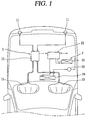
- FIG. 1 is a schematic view illustrating a vehicle mounted with a safety device according to the present disclosure.
- a safety device for vehicle according to the present embodiment may be provided to be electrically connected to an airbag system within the vehicle.
- An airbag system 1 may include a collision sensor (front/side impact sensors 11 provided at a front side or lateral surface of the relevant vehicle to determine whether the vehicle collides, an airbag control unit (ACU) 12 configured to determine whether the airbag operates based on an impulse sensed from the collision sensor 11, an inflator (not shown) configured to quickly generate gas when an airbag operation signal is generated, and a bag 13 configured to expand with the generated gas to substantially protect passengers.
- ACU airbag control unit
- the foregoing airbag system 1 may sense a collision signal transmitted to the airbag control unit 12 by allowing collision sensors 11 mounted on a front side portion and a lateral structural portion of the vehicle to sense a collision and sense a collision signal sensed through a sensor integrated into the airbag control unit 12 to determine whether the airbag control unit 12 expands through comprehensive calculations and then perform actual expansion.
- a time taken to perform the process is very short, approximately 0.02 second, and the status of power during expansion, an expanded time, whether or not a safety belt is used, and the like are written on the airbag control unit 12, and it is designed to allow airbag expansion for a predetermined period of time even when a battery is released due to a collision.
- a refrigeration cycle device 2 provided within the vehicle may be damaged to introduce refrigerant into the indoor.
- a safety device for discharging refrigerant within the refrigeration cycle in advance when the damage of the vehicle is expected in the middle of refrigeration cycle device 2 may be provided therein.
- the refrigerant is a harmful refrigerant such as CO 2 refrigerant
- refrigerant including CO 2 refrigerant will be commonly referred to as refrigerant.
- the refrigeration cycle device 2 for vehicle may include a compressor 21 for compressing refrigerant that circulates the refrigeration cycle, a condenser 22 for condensing the compressed refrigerant, and a receiver/driver (not shown) for separating the condensed refrigerant into gas-liquid while temporarily collecting refrigerant that circulates the refrigeration cycle, an expansion apparatus 23 for throttle-expanding liquid refrigerant separated into gas-liquid, and an evaporator 24 for evaporating the expanded refrigerant to return to the compressor.
- the compressor 21, the condenser 22, the receiver/driver and the expansion apparatus 23 are provided at an outside of the relevant vehicle, and the evaporator 24 is provided to communicate the indoor or outdoor. Accordingly, during a vehicle accident, part of refrigerant may be introduced into the indoor by the evaporator 24 or an accessory such as a refrigerant pipe or fan connected to the evaporator 24.
- a pressure relief valve (PRV) 100 as a safety device may be provided in the compressor (or in the middle of the refrigerant pipe of the refrigeration cycle) 21 as illustrated in the present embodiment.
- the PRV 100 may be provided at either a low pressure portion or a high pressure portion of the compressor 21, but according to the present embodiment, it may be provided at the high pressure portion, for an example.
- the PRV 100 may be coupled through one side of the compressor casing, namely, a rear cover 21a forming the high pressure portion.
- the PRV 100 may be configured to switch according to a change of internal pressure of the compressor 21, but also configured to be electrically connected to the ACU 12 and linked with the ACU 12.
- the PRV 100 may be connected to the ACU 12 to prevent harmful refrigerant from being introduced into the interior of the vehicle when an accident occurs, in addition to a function as a typical PRV, namely, the role of removing part of refrigerant in an excessive compression condition to allow the refrigeration cycle to maintain a proper pressure.
- the ACU 12 may transfer an operation signal to the PRV 100 prior to, at the same time or immediately subsequent to transferring an airbag operation signal to the inflator, and when the PRV 100 receives a signal from the ACU 12 to be opened, refrigerant in the high pressure portion may be discharged to an outside of the vehicle.
- Reference numeral 21b is a power connecting line.
- the PRV according to the present embodiment may be implemented in various forms.
- the PRV may be configured to remove a type of safety pin mechanically connected to the motor to open the valve when an accident occurs.
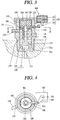
- FIG. 3 is a longitudinal cross-sectional view illustrating the PRV according to a comparative embodiment
- FIG. 4 is a cross-sectional view taken along line "IV-IV" in FIG. 3
- FIGS. 5 and 6 are schematic view illustrating a configuration for operating the PRV according to the comparative embodiment.
- the PRV 100 may include a valve housing 110 having an inlet 111 and an outlet 112, a piston valve 120 provided within the valve housing 110 to selectively switch the inlet 111, a valve spring 130 provided at a backpressure side of the piston valve 120 to limit the valve 120 from being opened, a spacer 140 passing through the valve housing 110 to adjust an elastic force of the valve spring 130, and a control unit 150 provided at one side of the valve housing 110 to operate the spacer 140.
- a fastening portion 113 for fastening a screw to the compressor 21 may be formed on an outer circumferential surface at an end of the valve housing 110.
- the valve housing 110 may be bonding-coupled to the compressor 21, but in this case, it may not be preferable because the PRV should be replaced at the same time when replacing the compressor 21 or part of the compressor. Accordingly, as illustrated in FIGS. 2 and 3 , it may be preferable to form a fastening groove 21c on the rear cover 21a of the compressor 21 to screw-couple an end of the PRV 100 to the fastening groove.
- valve housing 110 may be formed at the center of the fastening portion 113.
- valve housing 110 may be communicated with an inner space of the compressor 21 at any place.
- the outlet 112 of the valve housing 110 may be formed at a position included in an outside of the compressor 21, and a discharge guide pipe 114 for guiding refrigerant bypassed through the inlet 111 of the valve housing 110 to an outside of the vehicle may be connected to the outlet 112.
- the discharge guide pipe 114 may be preferably open toward the bottom surface of the vehicle, though not shown in the drawing, to effectively block refrigerant from being introduced into the indoor.
- a spacer hole 115 may be formed in a penetrating manner at a middle height of the valve housing 110 to slidably insert the spacer 140.
- the spacer hole 115 may be formed to be larger than a cross-sectional area of the spacer 140 not to be caught when releasing the spacer 140.
- valve guide 160 for guiding the movement of the piston valve 120 may be provided within the valve housing 110.
- the valve guide 160 may be inserted into an upper end of the valve housing 110 and closely fixed to a valve cover 170 covering an upper end of the valve housing 110.
- a guide portion 161 protruded toward the piston valve 120 is formed on a bottom surface of the valve guide 160.
- the guide portion 161 may be formed in a cylindrical shape to be slidably coupled to a sliding portion 122 of the piston valve 120 which will be described later.
- a valve portion 121 is formed at one end of the piston valve 120 to switch the inlet 111 of the valve housing 110, and the sliding portion 122 slidably coupled to the valve guide 160 to guide a linear movement may be formed on a rear side of the valve portion 121. Furthermore, a flange portion 123 may be formed between the valve portion 121 and the sliding portion 122 to support one end of the valve spring 130.
- the valve spring 130 is made of a compression coil spring and inserted into the sliding portion 122 of the piston valve 120, and one end of the valve spring 130 may be supported by the flange portion 123 of the piston valve 120, whereas the other end thereof is supported by a spring support plate 180 which will be described later.
- the spring support plate 180 is located between the spacer 140 and the valve spring 130 to prevent the valve spring 130 from being directly brought into contact with the spacer 140.
- the spring support plate 180 may be formed in a circular plate shape to form a guide hole 181 to allow the guide portion 161 of the valve guide 160 to pass through the center thereof.
- one side of the spring support plate 180 may be closed adhered to the spacer 140 as illustrated in FIG. 3 , and the other side thereof may be closely adhered to the a support 162 protruded from a bottom surface of the valve guide 160, but according to circumstances, may be supported only by the spacer 140 in a state that the support 162 of the valve guide 160 is excluded.
- the spring support plate 180 is supported by the support 162 of the valve guide 160 and the spacer 140, the spring support plate 180 is operated while inclining the spring support plate 180 when the PRV is operated, but the piston valve 120 is inclined by a gap between the guide portion 161 of the valve guide 160 and the sliding portion 122 of the piston valve 120 to open the inlet 111 of the valve housing 110.
- the spacer 140 performs the role of a type of safety pin, and is formed in a rectangular shape and slidably inserted and coupled to the spacer hole 115 of the valve housing 110.
- One end of the spacer 140 may be located between the valve guide 160 and the spring support plate 180, and the other end of the spacer 140 may be coupled to a connection portion 152 of the control unit 150 which will be described later.
- the spacer 140 may be disposed only at one side as illustrated in FIG. 3 , but a plurality of spacers 140 may be disposed at predetermined intervals along a circumferential direction according to circumstances. Furthermore, in case of a plurality of spacers 140, the control unit 150 may be independently provided at each spacer 140, but all of them may be connected to one control unit 150 using the connection portion 152 which will be described later.
- control unit 150 may include a motor unit 151 operated by external power, and a connection portion 152 coupled to a rotor of the motor unit 151 to operate the spacer 140 of the PRV.
- the motor unit 151 as a type of step motor, may be configured to receive power from the compressor controller or ACU 12 to reciprocally rotate within a predetermined angle.
- the motor unit 151 of the PRV 100 may be configured to receive an electrical signal through a photocoupler 25b and a current amplifier circuit 25c of the compressor controller 25 performing CAN communication through the ACU 12 and a CAN transceiver 25a as illustrated in FIG. 5 or connected to directly receive an electrical signal through an airbag explosion sensing circuit 12a, a photocoupler 12b and a current amplifier circuit 12c of the ACU 12 as illustrated in FIG. 6 .
- connection portion 152 may be formed with one cam link as illustrated in FIGS. 3 and 4 . However, though not shown in the drawing, it may be also formed in a reel-like shape.
- the motor unit 151 and connection portion 152 may be formed in a rack and pinion shape.
- reference numeral 153 is a rotating shaft.
- the foregoing safety device for vehicle according to the present embodiment may have the following operational effects.
- the sensed signal is transferred to the ACU 12 while at the same expanding the airbag 13, and the ACU 12 transfers an open signal to the control unit 150 of the PRV 100 through the compressor controller 25 as illustrated in FIG. 5 or in a direct manner as illustrated in FIG. 6 .
- the motor unit 151 of the control unit 150 that has received the signal is switched from a valve closed state as illustrated in FIG. 3 to a valve open state as illustrated in FIG. 7A .
- the connection portion 152 rotates in a counterclockwise direction of the drawing as illustrated in a dotted line in FIG. 4 .
- the connection portion 152 that is a cam link rotates to move the spacer 140 in the right direction of the drawing while at the same dragging the spacer 140, thereby moving the spacer 140 to a withdrawn position as illustrated in FIG. 7A .
- a space capable of moving upward by a distance of the spacer 140 from which the spring support plate 180 that has supported a backpressure side of the valve spring 130 is removed may be secured.
- the piston valve 120 may be pushed by an internal pressure of the compressor to move upward while reducing an elasticity of the valve spring 130 or creating a clearance.
- refrigerant is discharged to an outside of the compressor through the PRV 100 from an inner space of the compressor 21 as the inlet 111 and the outlet 112 provided on the valve housing 110 of the PRV 100 are communicated with each other.
- the discharge guide pipe 114 is connected to the outlet 112 of the valve housing 110 and the other end of the discharge guide pipe 114 is extended and formed toward the bottom of the vehicle, carbon dioxide refrigerant discharged from the compressor 21 is discharged to a side far from the interior of the vehicle.
- the PRV 100 is opened to prevent excessive compression regardless of the signal of the PRV 100.
- a predetermined pressure typically, 170 bar
- a force due to the internal pressure of the compressor 21 may push the piston valve 120 while exceeding an elasticity of the valve spring 130 to communicate the inlet 111 and outlet 112 of the valve housing 110 even though the spacer 140 is not pulled out as illustrated in FIG. 7C , thereby solving excessive compression.
- control unit may include a motor unit and a connection portion wherein the motor unit operates the connection portion according to a signal transferred from the ACU to directly move the spacer, but according to the present embodiment, the control unit may restrict or release the spacer to allow the spacer to move by an additional driving source.
- FIG. 8 is a longitudinal cross-sectional view illustrating an embodiment of a PRV according to the present invention
- FIGS. 9A and 9B are longitudinal cross-sectional views illustrating the operations of a PRV according to FIG. 8 .
- a PRV 200 according to the present invention includes a valve housing 210, a piston valve 220, a valve spring 230, a spacer 240, a control unit 250 and a valve guide 260, similarly to the foregoing embodiment.
- a spacer housing 270 is coupled to one side of the valve housing 210, and a return spring 280 for pushing the spacer 240 in a valve open direction is provided within the spacer housing 270.
- control unit 250 is provided with a stopper 290 on a mover instead of the connection portion of the foregoing embodiment, and configured to restrict or release the spacer 240 while moving according to whether or not power is applied.
- a restricting groove 241 may be formed on an upper surface of the spacer 240 to insert the stopper 290.
- the stopper 290 may be integrally extended and formed on the mover or additionally fabricated and assembled later.
- a sliding portion 261 slidably coupled to the spacer 240 is provided at an upper end of the valve guide 260, and a surface corresponding to the spacer 240 is formed on the sliding portion 261 to have an inclined surface 262 inclined in a direction opposite thereto.
- the valve guide 260 may be pushed by the spacer 240 according to the movement direction of the spacer 240 to pressurize the valve spring 230 in a closed direction so as to close the piston valve 220 or moved in an open direction to open the piston valve 220.
- valve guide 260 adjacent to the inclined surface 242 of the spacer 240 moves in an opposite direction to the inclined surface 242 of the spacer 240, thereby raising the valve guide 260.
- an elasticity of the valve spring 230 decreases as a gap between a valve portion 221 of the piston valve 220 and the valve guide 260 increases.
- the piston valve 220 is pushed out by a force due to an internal pressure of the compressor 21 to allow the inlet 211 and the outlet 212 of the valve housing 210 to communicate with each other.
- carbon dioxide within the compressor may be discharged to an outside of the vehicle along the valve housing 210 and discharge guide pipe 214, thereby preventing refrigerant from being introduced into the interior of the vehicle.
- the collision sensor when the collision sensor transfers a collision signal to the ACU, the ACU transfers an operation signal (open signal) to the PRV to operate the PRV so as to discharge refrigerant within the compressor to an outside of the vehicle, but according to the present embodiment, the collision sensor is configured to transfer the sensed signal directly to the PRV.
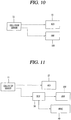
- FIGS. 10 through 12 are block diagrams for explaining the operation examples of a PRV according to the present embodiment.
- FIGS. 10 and 11 are views illustrating an operation example using a collision sensor
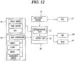
- FIG. 12 is an operation example using an advanced driver assistance system (ADAS).
- FIGS. 13A through 13F are block diagrams for explaining the operation state of a PRV and a HVAC for various situations during the driving of the vehicle.
- ADAS advanced driver assistance system
- FIG. 10 it may be configured to transfer the sensed signal to the ACU 12 and PRV 100, respectively, when a collision is sensed on the collision sensor 11. Compared to transferring a collision signal to the PRV 100 through the ACU 12 as illustrated in the foregoing embodiment, as the PRV 100 receives a signal directly from the collision sensor 11, the PRV 100 may be more quickly operated.
- FIG. 11 it may be configured such that when a collision is sensed on the collision sensor 11, the sensed signal is transferred to the ACU 12 and the electronic control unit (ECU) 30 within the vehicle, respectively to operate an airbag in the ACU 12 as well as transfer signals to the PRV 100 and heating, ventilation, and air conditioning (HVAC) unit 40, respectively, in the ECU 30.
- ECU electronice control unit
- the HVAC 40 may open or close an outdoor air inlet and an indoor air inlet, respectively, while at the same operating the PRV 100, thereby effectively blocking refrigerant from being introduced into the interior of the vehicle even when part of the carbon dioxide refrigerant is leaked prior to the operation of the PRV 100.
- the electronic control unit 30 within the vehicle may be configured to estimate or detect various situations such as whether or not there is a collision, or whether or not there is an overturn or plunge of the vehicle, or an estimated time-to-collision, or whether or not the PRV operates (open), or the like, using a collision sensor or various sensors (speed sensor, acceleration sensor, GPS, etc.) 50 and ADAS related components (camera, lidar, radar, ultrasonic sensor, etc.) 60 provided in the vehicle, thereby determining whether or not to operate (open) the PRV 100 and HVAC 40.
- a determination unit 31 for estimating the situation of the vehicle in advance may be provided therein, and an output unit 32 for determining and controlling whether or not to operate (open) the PRV 100 and HVAC 40 according to the estimation of the determination unit 31 may be provided therein.
- signals transferred from the sensors 50, 60 such as the camera or the like may be compared by the determination unit 31 to estimates whether or not the vehicle collides, and when the estimation result of the determination unit 31 is determined as a "vehicle collision" and transferred to the output unit 32, the ECU 30 may control the PRV 100 to be operated through the output unit 32 while at the same controlling an external air inlet and an internal air inlet of the HVAC 40 or the like to be closed, thereby preventing hazardous materials from being introduced into the vehicle in advance even when the damage of the compressor occurs during a collision.
- the collision sensor 11 may be electrically connected to the PRV 100 to control whether or not to operate the airbag.
- the present embodiment may be configured to compare an estimated time-to-collision of the vehicle with a manipulation time of the vehicle to operate (open) the PRV 100 and HVAC 40 in advance.
- a distance between an obstacle and the vehicle (relevant vehicle) is measured using the sensors 50, 60 such as the speed sensor, GPS, camera, or the like.
- the determination unit 31 compares a braking distance of the vehicle based on the measurement value, and estimates that the vehicle will collide with the obstacle when the distance (A) to the obstacle, which is a measurement value, is less or equal than the braking distance (B) of the vehicle. Then, the ECU 30 may control the PRV 100 to be operated through the output unit 32 to discharge refrigerant out of the vehicle or control the external air inlet and internal air inlet of the HVAC 40 or the like to be closed to block refrigerant that is a hazardous gas from being introduced into the vehicle.
- the ECU 30 may control the PRV 100 to be operated through the output unit 32 to discharge refrigerant out of the vehicle or control the external air inlet and internal air inlet of the HVAC 40 or the like to be closed to block refrigerant that is a hazardous gas from being introduced into the vehicle.
- the present embodiment may be configured to estimate or detect a collision amount of the vehicle to selectively operate (open) the PRV 100 and HVAC 40 according to a size of the collision amount.
- the determination unit 31 of the ECU 30 estimates and calculates a collision amount when the vehicle collides with the obstacle using signals transferred from the sensors 50, 60 such as the speed sensor, camera, or the like. Then, the determination unit 31 may compare the calculated collision amount with the stored reference value, and when the collision amount is greater than or equal to the reference value, the ECU 30 may control the PRV 100 to be operated through the output unit 32 to discharge refrigerant out of the vehicle or control the external air inlet and internal air inlet of the HVAC 40 or the like to be closed to block refrigerant that is a hazardous gas from being introduced into the vehicle.
- the ECU 30 may control the PRV 100 not to be operated through the output unit 32 while at the same allowing the external air inlet and internal air inlet of the HVAC 40 or the like to maintain a current state.
- the calculation of the collision amount may be carried out based on the speed of the vehicle, the property of the obstacle, a rear collision or side-rear collision, or the like.
- the present embodiment may be configured to estimate an overturn or plunge of the vehicle to operate (open) the PRV 100 and HVAC 40 in advance.
- the determination unit 31 of the ECU 30 detects a tilt of the vehicle, that is, the extent of vehicle being tilted with respect to a horizontal surface transferred from the sensors 50, 60 such as the gyro sensor, camera, or the like in real time, and estimates it as a "vehicle overturn" at the moment when the vehicle is turned over above 90 degrees with respect to a horizontal surface as a result of the detection. Then, the ECU 30 may control the PRV 100 to be operated through the output unit 32 to discharge refrigerant out of the vehicle or control the external air inlet and internal air inlet of the HVAC 40 or the like to be closed to block refrigerant that is a hazardous gas from being introduced into the vehicle.
- the determination unit 31 may detect a fall speed of the vehicle in real time using the sensors 50, 60 such as the gyro sensor, camera, or the like, and determines it as a "vehicle plunge" when the fall speed of the vehicle is close to a freefall speed as a result of the detection, and the ECU 30 may control the PRV 100 to be operated through the output unit 32 to discharge refrigerant out of the vehicle or control the external air inlet and internal air inlet of the HVAC 40 or the like to be closed to block refrigerant that is a hazardous gas from being introduced into the vehicle Furthermore, as illustrated in FIG.
- the determination unit 31 may detect a height variation rate during the driving of the vehicle using the sensors 50, 60 such as the gyro sensor, camera, or the like, and determine it as a "vehicle plunge" when the height variation rate during the driving of the vehicle exceeds or equal to [a statutory slope rate (sin) for each road x vehicle maximum speed] as a result of the detection, and the ECU 30 may control the PRV 100 to be operated through the output unit 32 to discharge refrigerant out of the vehicle or control the external air inlet and internal air inlet of the HVAC 40 or the like to be closed to block refrigerant that is a hazardous gas from being introduced into the vehicle.
- the sensors 50, 60 such as the gyro sensor, camera, or the like
- the ECU 30 may control the PRV 100 to be operated through the output unit 32 to discharge refrigerant out of the vehicle or control the external air inlet and internal air inlet of the HVAC 40 or the like to be closed to block refrigerant that is a hazardous gas from being introduced
Description
- The present disclosure relates to a safety device for vehicle, and particularly, to a safety device for vehicle for preventing refrigerant in a refrigeration cycle for vehicle from being introduced into an interior of a vehicle.
- In general, an air conditioning apparatus for vehicle may include a compressor for compressing refrigerant that circulates a refrigeration cycle, a condenser for condensing the compressed refrigerant, a receiver/dryer for dividing the condensed refrigerant into gas and liquid while temporarily collecting refrigerant that circulates the refrigeration cycle, an expansion apparatus for throttle-expanding liquid refrigerant that has been divided into gas and liquid, and an evaporator for evaporating the expanded refrigerant to return to the compressor.
- Alternative freon (HFC-134a) has been used as refrigerant in a refrigeration cycle in an air conditioning apparatus for vehicle, but in recent years, refrigerant having a small global warming coefficient has been required to suppress global warming. For such refrigerants, carbon dioxide (CO2), HFC-152a, butane, propane, and the like are known, for example.
- However, when such refrigerants are used for refrigerant in an air conditioning apparatus, in case where an evaporator installed in an interior of a vehicle or an interior pipe of a vehicle is damaged by a vehicle accident or the like, refrigerant may be introduced into the interior of the vehicle. In particular, when the refrigerant is carbon dioxide refrigerant, a vehicle occupant may suffocate due to lack of oxygen, and when the refrigerant is flammable refrigerant such as HFC-152a or the like, it may cause serious risk such as an incidence of fire.
- Accordingly, even when a crack occurs due to aging of the evaporator or other reasons or a constituent element in the refrigeration cycle undergoes serious damage due to a vehicle accident or the like, it may be required not to introduce refrigerant within the refrigeration cycle into the interior of the vehicle.
- In the related art, technologies have been introduced that relief devices are attached to a high pressure side and a low pressure side of the compressor, respectively, in an air conditioning apparatus for vehicle using flammable refrigerant, and the relief devices are operated to discharge flammable refrigerant within the refrigeration cycle to an outside of the vehicle when a collision accident occurs in which an airbag is operated by an airbag control unit (ACU).
- However, in case of the related art, the relief devices may be operated dependent on a collision sensor, and therefore, there is a limit in quickly discharging leaked refrigerant to an outside of the vehicle.
- Furthermore, the relief devices may be operated in a posteriori manner since a collision occurs, and thus there is a concern of introducing a small amount of refrigerant to an interior of the vehicle.
- Furthermore, the relief devices may be unnecessarily operated even when refrigerant is not leaked in practice as they are operated without considering the leakage possibility of refrigerant, thereby increasing the maintenance cost of components due to exchanging the relief devices.
- Furthermore, an excessive compression prevention valve for resolving excessive compression may be additionally provided when excessive compression occurs due to various reasons in an air conditioning apparatus for vehicle, thereby increasing the fabrication cost due to an increased number of components.
-
EP 1 481 827 A1 -
US 4,133,186 relates to a combination of an overpressure relief valve and low-pressure electrical cut-off valve for an automotive air conditioning system. The valve includes a spring retainer that is axially adjustable by rotation thereof. -
US 3,933,005 relates to a relief valve combined with an electromagnetic clutch disconnect switch activated when high-pressure conditions occur. The terminal is attached to a conductor wire and passes through a cup-shaped connector. If the pressure level in a space of the connector increases until the connector is distorted sufficiently, and edge of the connector is removed from a groove, so that the connector falls away and disengages the terminal member to open an electromagnetic circuit and deactivate a compressor. - An aspect of the present disclosure is to provide a safety device for vehicle capable of quickly discharging leaked refrigerant to an outside of the vehicle when harmful refrigerant such as carbon dioxide is applied.
- Another aspect of the present disclosure is to provide a safety device for vehicle capable of estimating an environment of refrigerant leakage in advance to discharge refrigerant in advance to an outside of the vehicle when harmful refrigerant such as carbon dioxide is applied.
- Still another aspect of the present disclosure is to provide a safety device for vehicle capable of calculating the probability of refrigerant leakage to discharge refrigerant to an outside of the vehicle only when required when harmful refrigerant such as carbon dioxide is applied.
- Yet still another aspect of the present disclosure is to provide a safety device for vehicle capable of being controlled by a control device to discharge refrigerant to an outside of the vehicle during a collision of the vehicle as well as being operated by a pressure with no additional control to discharge refrigerant during excessive compression.
- Still yet another aspect of the present disclosure is to provide a safety device for vehicle capable of implementing a switching operation in a stable and accurate manner.
- In order to accomplish the objective of the present disclosure, there is provided a compressor provided within a vehicle to constitute a refrigeration cycle and compress refrigerant; a safety device for a vehicle according to
claim 1, including an impulse sensor provided in a vehicle to allow the relevant vehicle to sense an impulse received from an outside; and a safety valve provided in the compressor to have a switching unit for selectively communicating an inner space of the compressor with an outside of the compressor, in which the switching unit is electrically connected to the impulse sensor to discharge refrigerant in the inner space of the compressor out of the compressor while the switching unit is opened when an impulse sensed by the impulse sensor exceeds a predetermined range. - Here, the safety valve may be electrically connected to an airbag control unit (ACU) or electronic control unit (ECU) to link a motor unit that receives electrical signals with the airbag control unit provided in the vehicle or the electronic control unit electrically connected to various sensors within the vehicle.
- Furthermore, the electronic control unit may be provided with a determination unit configured to estimate and determine whether the vehicle collides based on signals transferred through the various sensors, and provided with an output unit configured to control a heating, ventilation, and air conditioning (HVAC) unit provided within the vehicle according to the determination unit.
- Furthermore, the motor unit of the safety valve may be directly connected to an output terminal of the airbag control unit or electronic control unit.
- Furthermore, the motor unit of the safety valve may be electrically connected to an output terminal of a compressor controller configured to control the compressor, and an input terminal of the compressor controller may be electrically connected to an output terminal of the airbag control unit or electronic control unit.
- Furthermore, the safety valve may be provided with a discharge port configured to discharge the refrigerant within the compressor to the outside of the compressor, and the discharge port may be provided with a discharge guide pipe configured to guide the refrigerant of the compressor to an outside of the vehicle.
- Furthermore, the safety valve may be configured to open a switching unit when an internal pressure of the compressor is above a predetermined pressure.
- Here, the safety valve includes a valve housing having an inlet and an outlet; a piston valve provided within the valve housing to selectively communicate between the inlet and the outlet; a valve spring provided at a backpressure side of the piston valve to limit the piston valve from being opened; a spacer inserted through the valve housing to adjust an elastic force of the valve spring; and a control unit provided at one side of the valve housing to operate the spacer.
- Here, the control unit includes a motor unit configured to receive power from an outside to operate; and a connection portion coupled between the motor unit and the spacer to transfer a driving force of the motor unit to the spacer to move the spacer. Furthermore, a valve guide configured to guide the movement of the piston valve is further provided within the valve housing, and a guide portion into which a sliding portion of the piston valve is slidably inserted is formed on the valve guide in a switching direction of the piston.
- Furthermore, the control unit includes a motor unit configured to receive power from an outside to operate; a stopper provided in the motor unit to restrict or release the movement of the spacer while being moved by the motor unit; and a return spring configured to support the stopper, and move the stopper when the stopper is released from the spacer.
- Furthermore, a valve guide configured to guide the movement of the piston valve is further provided within the valve housing, and the valve guide is slidably coupled to the spacer, and a surface on which the valve guide and the spacer are brought into contact may be formed in an inclined manner to move the spacer and the valve guide in an orthogonal direction.
- In order to accomplish the objective of the present disclosure, there is provided a safety device for vehicle, including a refrigeration cycle unit provided in a vehicle to heat or cool a passenger compartment of the vehicle; an electronic control unit (ECU) provided in the vehicle to control various functions of the vehicle; and a refrigerant discharge unit electrically connected to the electronic control unit to selectively discharge the refrigerant of the refrigeration cycle to an outside of the vehicle while being linked with the electronic control valve.
- Here, the electronic control unit may be configured to calculate a shock received by the vehicle, and provide an open signal to the refrigerant discharge unit or close an air path of the refrigeration cycle unit when the value is greater than or equal to a predetermined range.
- Furthermore, the electronic control unit is configured to estimate or detect an estimated time-to-collision and a braking time of the vehicle, and provide an open signal to the refrigerant discharge unit or close an air path of the refrigeration cycle unit based on the estimated time-to-collision and the braking time of the vehicle. Here, the electronic control unit is configured to compare the estimated time-to-collision and the braking time of the vehicle, and provide an open signal to the refrigerant discharge unit or close an air path of the refrigeration cycle unit when the estimated time-to-collision of the vehicle is less or equal than the braking time of the vehicle.
- Furthermore, the electronic control unit is configured to estimate or detect a collision amount of the vehicle, and provide a close signal to the refrigerant discharge unit based on the collision amount of the vehicle.
- Here, the electronic control unit is configured to provide a close signal to the refrigerant discharge unit when the collision amount is less or equal than a reference value.
- Furthermore, the electronic control unit is configured to detect a tilt of the vehicle defined by the extent of vehicle being tilted with respect to a horizontal surface, and provide an open signal to the refrigerant discharge unit or close an air path of the refrigeration cycle unit based on the tilt of the vehicle.
- Here, the electronic control unit is configured to provide an open signal to the refrigerant discharge unit or close an air path of the refrigeration cycle unit using when the tilt of the vehicle is above 90 degrees.
- Furthermore, the electronic control unit is configured to detect a fall speed of the vehicle, and provide an open signal to the refrigerant discharge unit or close an air path of the refrigeration cycle unit based on when the fall speed of the vehicle.
- Here, the electronic control unit is configured to compare a fall speed with a freefall speed of the vehicle, and provide an open signal to the refrigerant discharge unit or close an air path of the refrigeration cycle unit when the fall speed of the vehicle is close to the freefall speed.
- Furthermore, wherein the electronic control unit is configured to detect a height variation rate during the driving of the vehicle, and provide an open signal to the refrigerant discharge unit or close an air path of the refrigeration cycle unit based on the height variation rate during the driving of the vehicle.
- Here, the electronic control unit is configured to provide an open signal to the refrigerant discharge unit or close an air path of the refrigeration cycle unit when a height variation rate during the driving of the vehicle exceeds or equal to [a statutory slope rate (sin) for each road x vehicle maximum speed].
- Furthermore, the refrigerant discharge unit may be detachably provided on a compressor constituting the refrigeration cycle.
- Furthermore, an inlet may be formed at one side of the refrigerant discharge unit to communicate with an inner space of the compressor, and an outlet may be formed at the other side of the refrigerant discharge unit to communicate toward an outside of the vehicle, and a valve configured to receive an electrical signal transferred from the electronic control unit and selectively switch between the inlet and outlet of the refrigerant discharge unit may be provided within the refrigerant discharge unit.
- The accompanying drawings, which are included to provide a further understanding of the invention and are incorporated in and constitute a part of this specification, illustrate embodiments of the invention and together with the description serve to explain the principles of the invention.
- In the drawings:
-
FIG. 1 is a schematic view illustrating a vehicle mounted with a safety device according to the present disclosure; -
FIG. 2 is a piston valve illustrating the appearance of a compressor mounted with a safety device according toFIG. 1 ; -
FIG. 3 is a longitudinal cross-sectional view illustrating a pressure relief valve (PRV) according to a comparative embodiment; -
FIG. 4 is a cross-sectional view taken along line "IV-IV" inFIG. 3 ; -
FIGS. 5 and 6 are schematic view illustrating a configuration for operating a PRV according to the present embodiment; -
FIGS. 7A and7B are longitudinal cross-sectional views illustrating the operations of a PRV according toFIG. 3 , in whichFIG. 7A is a view illustrating an operation when a collision occurs, andFIG. 7B is a view illustrating an operation when excessive compression occurs; -
FIG. 8 is a longitudinal cross-sectional view illustrating another embodiment of a PRV according to the present invention; -
FIGS. 9A and 9B are longitudinal cross-sectional views illustrating the operations of a PRV according toFIG. 8 , in whichFIG. 9A is a view illustrating an operation when a collision occurs, andFIG. 9B is a view illustrating an operation when excessive compression occurs; -
FIGS. 10 through 12 are block diagrams for explaining the operation examples of a PRV according to the present embodiment, in whichFIGS. 10 and 11 are views illustrating an operation example using a collision sensor, andFIG. 12 is an operation example using an advanced driver assistance system; and -
FIGS. 13A through 13F are block diagrams for explaining the operation state of a PRV and a HVAC for various situations during the driving of the vehicle. - Hereinafter, a safety device for vehicle according to the present disclosure will be described in detail based on an embodiment illustrated in the accompanying drawings.
-
FIG. 1 is a schematic view illustrating a vehicle mounted with a safety device according to the present disclosure. As illustrated herein, a safety device for vehicle according to the present embodiment may be provided to be electrically connected to an airbag system within the vehicle. - An
airbag system 1 may include a collision sensor (front/side impact sensors 11 provided at a front side or lateral surface of the relevant vehicle to determine whether the vehicle collides, an airbag control unit (ACU) 12 configured to determine whether the airbag operates based on an impulse sensed from thecollision sensor 11, an inflator (not shown) configured to quickly generate gas when an airbag operation signal is generated, and abag 13 configured to expand with the generated gas to substantially protect passengers. - The foregoing
airbag system 1 may sense a collision signal transmitted to theairbag control unit 12 by allowingcollision sensors 11 mounted on a front side portion and a lateral structural portion of the vehicle to sense a collision and sense a collision signal sensed through a sensor integrated into theairbag control unit 12 to determine whether theairbag control unit 12 expands through comprehensive calculations and then perform actual expansion. - Furthermore, a time taken to perform the process is very short, approximately 0.02 second, and the status of power during expansion, an expanded time, whether or not a safety belt is used, and the like are written on the
airbag control unit 12, and it is designed to allow airbag expansion for a predetermined period of time even when a battery is released due to a collision. - However, in a circumstance during the operation of an airbag, a
refrigeration cycle device 2 provided within the vehicle may be damaged to introduce refrigerant into the indoor. Accordingly, a safety device for discharging refrigerant within the refrigeration cycle in advance when the damage of the vehicle is expected in the middle ofrefrigeration cycle device 2 may be provided therein. In particular, in case where the refrigerant is a harmful refrigerant such as CO2 refrigerant, it is important to discharge refrigerant in advance to an outside of the vehicle since the driver is in danger when the refrigerant is introduced into the interior of the vehicle. Hereinafter, refrigerant including CO2 refrigerant will be commonly referred to as refrigerant. - As illustrated in
FIG. 1 , therefrigeration cycle device 2 for vehicle may include acompressor 21 for compressing refrigerant that circulates the refrigeration cycle, acondenser 22 for condensing the compressed refrigerant, and a receiver/driver (not shown) for separating the condensed refrigerant into gas-liquid while temporarily collecting refrigerant that circulates the refrigeration cycle, anexpansion apparatus 23 for throttle-expanding liquid refrigerant separated into gas-liquid, and anevaporator 24 for evaporating the expanded refrigerant to return to the compressor. - Among them, the
compressor 21, thecondenser 22, the receiver/driver and theexpansion apparatus 23 are provided at an outside of the relevant vehicle, and theevaporator 24 is provided to communicate the indoor or outdoor. Accordingly, during a vehicle accident, part of refrigerant may be introduced into the indoor by theevaporator 24 or an accessory such as a refrigerant pipe or fan connected to theevaporator 24. - In consideration of this, a pressure relief valve (PRV) 100 as a safety device may be provided in the compressor (or in the middle of the refrigerant pipe of the refrigeration cycle) 21 as illustrated in the present embodiment. The
PRV 100 may be provided at either a low pressure portion or a high pressure portion of thecompressor 21, but according to the present embodiment, it may be provided at the high pressure portion, for an example. - As illustrated in
FIG. 2 , thePRV 100 according to the present embodiment may be coupled through one side of the compressor casing, namely, arear cover 21a forming the high pressure portion. - The
PRV 100 may be configured to switch according to a change of internal pressure of thecompressor 21, but also configured to be electrically connected to theACU 12 and linked with theACU 12. When linked with theACU 12, thePRV 100 may be connected to theACU 12 to prevent harmful refrigerant from being introduced into the interior of the vehicle when an accident occurs, in addition to a function as a typical PRV, namely, the role of removing part of refrigerant in an excessive compression condition to allow the refrigeration cycle to maintain a proper pressure. As a result, theACU 12 may transfer an operation signal to thePRV 100 prior to, at the same time or immediately subsequent to transferring an airbag operation signal to the inflator, and when thePRV 100 receives a signal from theACU 12 to be opened, refrigerant in the high pressure portion may be discharged to an outside of the vehicle.Reference numeral 21b is a power connecting line. - The PRV according to the present embodiment may be implemented in various forms. For example, the PRV may be configured to remove a type of safety pin mechanically connected to the motor to open the valve when an accident occurs.
-
FIG. 3 is a longitudinal cross-sectional view illustrating the PRV according to a comparative embodiment, andFIG. 4 is a cross-sectional view taken along line "IV-IV" inFIG. 3 , andFIGS. 5 and 6 are schematic view illustrating a configuration for operating the PRV according to the comparative embodiment. - As illustrated in the drawing, the
PRV 100 according to the present embodiment may include avalve housing 110 having aninlet 111 and anoutlet 112, apiston valve 120 provided within thevalve housing 110 to selectively switch theinlet 111, avalve spring 130 provided at a backpressure side of thepiston valve 120 to limit thevalve 120 from being opened, aspacer 140 passing through thevalve housing 110 to adjust an elastic force of thevalve spring 130, and acontrol unit 150 provided at one side of thevalve housing 110 to operate thespacer 140. - A
fastening portion 113 for fastening a screw to thecompressor 21 may be formed on an outer circumferential surface at an end of thevalve housing 110. Of course, thevalve housing 110 may be bonding-coupled to thecompressor 21, but in this case, it may not be preferable because the PRV should be replaced at the same time when replacing thecompressor 21 or part of the compressor. Accordingly, as illustrated inFIGS. 2 and3 , it may be preferable to form afastening groove 21c on therear cover 21a of thecompressor 21 to screw-couple an end of thePRV 100 to the fastening groove. - Furthermore, the
inlet 111 of thevalve housing 110 may be formed at the center of thefastening portion 113. Of course, thevalve housing 110 may be communicated with an inner space of thecompressor 21 at any place. - Furthermore, the
outlet 112 of thevalve housing 110 may be formed at a position included in an outside of thecompressor 21, and adischarge guide pipe 114 for guiding refrigerant bypassed through theinlet 111 of thevalve housing 110 to an outside of the vehicle may be connected to theoutlet 112. Thedischarge guide pipe 114 may be preferably open toward the bottom surface of the vehicle, though not shown in the drawing, to effectively block refrigerant from being introduced into the indoor. - Furthermore, a
spacer hole 115 may be formed in a penetrating manner at a middle height of thevalve housing 110 to slidably insert thespacer 140. Thespacer hole 115 may be formed to be larger than a cross-sectional area of thespacer 140 not to be caught when releasing thespacer 140. - Furthermore, a
valve guide 160 for guiding the movement of thepiston valve 120 may be provided within thevalve housing 110. Thevalve guide 160 may be inserted into an upper end of thevalve housing 110 and closely fixed to avalve cover 170 covering an upper end of thevalve housing 110. - A
guide portion 161 protruded toward thepiston valve 120 is formed on a bottom surface of thevalve guide 160. Theguide portion 161 may be formed in a cylindrical shape to be slidably coupled to a slidingportion 122 of thepiston valve 120 which will be described later. - A
valve portion 121 is formed at one end of thepiston valve 120 to switch theinlet 111 of thevalve housing 110, and the slidingportion 122 slidably coupled to thevalve guide 160 to guide a linear movement may be formed on a rear side of thevalve portion 121. Furthermore, aflange portion 123 may be formed between thevalve portion 121 and the slidingportion 122 to support one end of thevalve spring 130. - The
valve spring 130 is made of a compression coil spring and inserted into the slidingportion 122 of thepiston valve 120, and one end of thevalve spring 130 may be supported by theflange portion 123 of thepiston valve 120, whereas the other end thereof is supported by aspring support plate 180 which will be described later. Thespring support plate 180 is located between thespacer 140 and thevalve spring 130 to prevent thevalve spring 130 from being directly brought into contact with thespacer 140. Thespring support plate 180 may be formed in a circular plate shape to form aguide hole 181 to allow theguide portion 161 of thevalve guide 160 to pass through the center thereof. - Furthermore, one side of the
spring support plate 180 may be closed adhered to thespacer 140 as illustrated inFIG. 3 , and the other side thereof may be closely adhered to the asupport 162 protruded from a bottom surface of thevalve guide 160, but according to circumstances, may be supported only by thespacer 140 in a state that thesupport 162 of thevalve guide 160 is excluded. In case where thespring support plate 180 is supported by thesupport 162 of thevalve guide 160 and thespacer 140, thespring support plate 180 is operated while inclining thespring support plate 180 when the PRV is operated, but thepiston valve 120 is inclined by a gap between theguide portion 161 of thevalve guide 160 and the slidingportion 122 of thepiston valve 120 to open theinlet 111 of thevalve housing 110. - The
spacer 140 performs the role of a type of safety pin, and is formed in a rectangular shape and slidably inserted and coupled to thespacer hole 115 of thevalve housing 110. One end of thespacer 140 may be located between thevalve guide 160 and thespring support plate 180, and the other end of thespacer 140 may be coupled to aconnection portion 152 of thecontrol unit 150 which will be described later. - Furthermore, the
spacer 140 may be disposed only at one side as illustrated inFIG. 3 , but a plurality ofspacers 140 may be disposed at predetermined intervals along a circumferential direction according to circumstances. Furthermore, in case of a plurality ofspacers 140, thecontrol unit 150 may be independently provided at eachspacer 140, but all of them may be connected to onecontrol unit 150 using theconnection portion 152 which will be described later. - On the other hand, the
control unit 150 may include amotor unit 151 operated by external power, and aconnection portion 152 coupled to a rotor of themotor unit 151 to operate thespacer 140 of the PRV. - The
motor unit 151 as a type of step motor, may be configured to receive power from the compressor controller orACU 12 to reciprocally rotate within a predetermined angle. For example, themotor unit 151 of thePRV 100 may be configured to receive an electrical signal through aphotocoupler 25b and acurrent amplifier circuit 25c of thecompressor controller 25 performing CAN communication through theACU 12 and aCAN transceiver 25a as illustrated inFIG. 5 or connected to directly receive an electrical signal through an airbagexplosion sensing circuit 12a, aphotocoupler 12b and acurrent amplifier circuit 12c of theACU 12 as illustrated inFIG. 6 . - The
connection portion 152 may be formed with one cam link as illustrated inFIGS. 3 and 4 . However, though not shown in the drawing, it may be also formed in a reel-like shape. - Furthermore, though not shown in the drawing, the
motor unit 151 andconnection portion 152 may be formed in a rack and pinion shape. - Among the drawings,
reference numeral 153 is a rotating shaft. - The foregoing safety device for vehicle according to the present embodiment may have the following operational effects.
- In other words, when a collision is sensed by the
collision sensor 11 provided at a front side or lateral surface of the relevant vehicle, the sensed signal is transferred to theACU 12 while at the same expanding theairbag 13, and theACU 12 transfers an open signal to thecontrol unit 150 of thePRV 100 through thecompressor controller 25 as illustrated inFIG. 5 or in a direct manner as illustrated inFIG. 6 . - Then, the
motor unit 151 of thecontrol unit 150 that has received the signal is switched from a valve closed state as illustrated inFIG. 3 to a valve open state as illustrated inFIG. 7A . In other words, when themotor unit 151 is operated by a signal received from theACU 12, theconnection portion 152 rotates in a counterclockwise direction of the drawing as illustrated in a dotted line inFIG. 4 . Here, theconnection portion 152 that is a cam link rotates to move thespacer 140 in the right direction of the drawing while at the same dragging thespacer 140, thereby moving thespacer 140 to a withdrawn position as illustrated inFIG. 7A . - Then, a space capable of moving upward by a distance of the
spacer 140 from which thespring support plate 180 that has supported a backpressure side of thevalve spring 130 is removed may be secured. Here, thepiston valve 120 may be pushed by an internal pressure of the compressor to move upward while reducing an elasticity of thevalve spring 130 or creating a clearance. - Then, refrigerant is discharged to an outside of the compressor through the
PRV 100 from an inner space of thecompressor 21 as theinlet 111 and theoutlet 112 provided on thevalve housing 110 of thePRV 100 are communicated with each other. Here, as one end of thedischarge guide pipe 114 is connected to theoutlet 112 of thevalve housing 110 and the other end of thedischarge guide pipe 114 is extended and formed toward the bottom of the vehicle, carbon dioxide refrigerant discharged from thecompressor 21 is discharged to a side far from the interior of the vehicle. - On the other hand, when excessive compression occurs in the
compressor 21 of the refrigeration cycle device 20 due to other reasons though the vehicle normally performs driving, thePRV 100 is opened to prevent excessive compression regardless of the signal of thePRV 100. In other words, when an internal pressure of the compressor increases greater than or equal to a predetermined pressure (typically, 170 bar), a force due to the internal pressure of thecompressor 21 may push thepiston valve 120 while exceeding an elasticity of thevalve spring 130 to communicate theinlet 111 andoutlet 112 of thevalve housing 110 even though thespacer 140 is not pulled out as illustrated inFIG. 7C , thereby solving excessive compression. - An embodiment of the PRV according to the present invention will be described as follows.
- In other words, according to the foregoing embodiment, the control unit may include a motor unit and a connection portion wherein the motor unit operates the connection portion according to a signal transferred from the ACU to directly move the spacer, but according to the present embodiment, the control unit may restrict or release the spacer to allow the spacer to move by an additional driving source.
-
FIG. 8 is a longitudinal cross-sectional view illustrating an embodiment of a PRV according to the present invention, andFIGS. 9A and 9B are longitudinal cross-sectional views illustrating the operations of a PRV according toFIG. 8 . As illustrated inFIG. 8 , aPRV 200 according to the present invention includes avalve housing 210, apiston valve 220, avalve spring 230, aspacer 240, acontrol unit 250 and avalve guide 260, similarly to the foregoing embodiment. - However, according to the present invention, a
spacer housing 270 is coupled to one side of thevalve housing 210, and areturn spring 280 for pushing thespacer 240 in a valve open direction is provided within thespacer housing 270. - Furthermore, the
control unit 250 is provided with astopper 290 on a mover instead of the connection portion of the foregoing embodiment, and configured to restrict or release thespacer 240 while moving according to whether or not power is applied. A restrictinggroove 241 may be formed on an upper surface of thespacer 240 to insert thestopper 290. Thestopper 290 may be integrally extended and formed on the mover or additionally fabricated and assembled later. - Furthermore, a sliding
portion 261 slidably coupled to thespacer 240 is provided at an upper end of thevalve guide 260, and a surface corresponding to thespacer 240 is formed on the slidingportion 261 to have aninclined surface 262 inclined in a direction opposite thereto. As a result, thevalve guide 260 may be pushed by thespacer 240 according to the movement direction of thespacer 240 to pressurize thevalve spring 230 in a closed direction so as to close thepiston valve 220 or moved in an open direction to open thepiston valve 220. - As illustrated in
FIG. 9A , when themotor unit 251 of thecontrol unit 250 receives a signal from theACU 12 to allow thestopper 290 coupled to the mover to move in an upward direction, thestopper 290 is released from the restrictinggroove 241 of thespacer 240. Here, thespacer 240 is pushed to the right side of the drawing by thereturn spring 280. - Then, the
inclined surface 262 of thevalve guide 260 adjacent to theinclined surface 242 of thespacer 240 moves in an opposite direction to theinclined surface 242 of thespacer 240, thereby raising thevalve guide 260. Here, an elasticity of thevalve spring 230 decreases as a gap between avalve portion 221 of thepiston valve 220 and thevalve guide 260 increases. - Then, the
piston valve 220 is pushed out by a force due to an internal pressure of thecompressor 21 to allow theinlet 211 and theoutlet 212 of thevalve housing 210 to communicate with each other. - Then, carbon dioxide within the compressor may be discharged to an outside of the vehicle along the
valve housing 210 and dischargeguide pipe 214, thereby preventing refrigerant from being introduced into the interior of the vehicle. - On the other hand, as illustrated in
FIG. 9B , when an internal pressure of the compressor is greater than or equal to a predetermined pressure (typically, 170 bar) even in a state that thespacer 240 is restricted by thecontrol unit 250, a force due to the internal pressure of the compressor may exceed an elastic force of thevalve spring 230 to push up thepiston valve 220, thereby allowing theinlet 211 and theoutlet 212 of thevalve housing 210 to communicate with each other. In this case, the PRV performs the role of preventing excessive compression in the compressor without receiving a signal from the ACU as illustrated in the foregoing embodiment. The operational effects thereof are similar to those of the foregoing embodiment, and thus the detailed description thereof will be omitted. - On the other hand, another embodiment of the operation method of the PRV according to the present invention will be described as follows.
- In other words, according to the foregoing embodiment, when the collision sensor transfers a collision signal to the ACU, the ACU transfers an operation signal (open signal) to the PRV to operate the PRV so as to discharge refrigerant within the compressor to an outside of the vehicle, but according to the present embodiment, the collision sensor is configured to transfer the sensed signal directly to the PRV.
-
FIGS. 10 through 12 are block diagrams for explaining the operation examples of a PRV according to the present embodiment.FIGS. 10 and 11 are views illustrating an operation example using a collision sensor, andFIG. 12 is an operation example using an advanced driver assistance system (ADAS).FIGS. 13A through 13F are block diagrams for explaining the operation state of a PRV and a HVAC for various situations during the driving of the vehicle. - According to an embodiment of
FIG. 10 , it may be configured to transfer the sensed signal to theACU 12 andPRV 100, respectively, when a collision is sensed on thecollision sensor 11. Compared to transferring a collision signal to thePRV 100 through theACU 12 as illustrated in the foregoing embodiment, as thePRV 100 receives a signal directly from thecollision sensor 11, thePRV 100 may be more quickly operated. - Furthermore, according to an embodiment of
FIG. 11 , it may be configured such that when a collision is sensed on thecollision sensor 11, the sensed signal is transferred to theACU 12 and the electronic control unit (ECU) 30 within the vehicle, respectively to operate an airbag in theACU 12 as well as transfer signals to thePRV 100 and heating, ventilation, and air conditioning (HVAC)unit 40, respectively, in theECU 30. - As a result, the
HVAC 40 may open or close an outdoor air inlet and an indoor air inlet, respectively, while at the same operating thePRV 100, thereby effectively blocking refrigerant from being introduced into the interior of the vehicle even when part of the carbon dioxide refrigerant is leaked prior to the operation of thePRV 100. - Furthermore, according to an embodiment of
FIG. 12 , theelectronic control unit 30 within the vehicle may be configured to estimate or detect various situations such as whether or not there is a collision, or whether or not there is an overturn or plunge of the vehicle, or an estimated time-to-collision, or whether or not the PRV operates (open), or the like, using a collision sensor or various sensors (speed sensor, acceleration sensor, GPS, etc.) 50 and ADAS related components (camera, lidar, radar, ultrasonic sensor, etc.) 60 provided in the vehicle, thereby determining whether or not to operate (open) thePRV 100 andHVAC 40. - To this end, according to the present embodiment, a
determination unit 31 for estimating the situation of the vehicle in advance may be provided therein, and anoutput unit 32 for determining and controlling whether or not to operate (open) thePRV 100 andHVAC 40 according to the estimation of thedetermination unit 31 may be provided therein. - For example, as illustrated in
FIG. 13A , signals transferred from thesensors determination unit 31 to estimates whether or not the vehicle collides, and when the estimation result of thedetermination unit 31 is determined as a "vehicle collision" and transferred to theoutput unit 32, theECU 30 may control thePRV 100 to be operated through theoutput unit 32 while at the same controlling an external air inlet and an internal air inlet of theHVAC 40 or the like to be closed, thereby preventing hazardous materials from being introduced into the vehicle in advance even when the damage of the compressor occurs during a collision. Of course, even in this case, thecollision sensor 11 may be electrically connected to thePRV 100 to control whether or not to operate the airbag. - On the other hand, the present embodiment may be configured to compare an estimated time-to-collision of the vehicle with a manipulation time of the vehicle to operate (open) the
PRV 100 andHVAC 40 in advance. - For example, as illustrated in
FIG. 13B , a distance between an obstacle and the vehicle (relevant vehicle) is measured using thesensors determination unit 31 compares a braking distance of the vehicle based on the measurement value, and estimates that the vehicle will collide with the obstacle when the distance (A) to the obstacle, which is a measurement value, is less or equal than the braking distance (B) of the vehicle. Then, theECU 30 may control thePRV 100 to be operated through theoutput unit 32 to discharge refrigerant out of the vehicle or control the external air inlet and internal air inlet of theHVAC 40 or the like to be closed to block refrigerant that is a hazardous gas from being introduced into the vehicle. - Furthermore, in this case, whether or not to be avoidable with the maximum steering manipulation may be determined, and when determined that it is unavoidable even with the maximum steering manipulation, as described above, the
ECU 30 may control thePRV 100 to be operated through theoutput unit 32 to discharge refrigerant out of the vehicle or control the external air inlet and internal air inlet of theHVAC 40 or the like to be closed to block refrigerant that is a hazardous gas from being introduced into the vehicle. - On the other hand, the present embodiment may be configured to estimate or detect a collision amount of the vehicle to selectively operate (open) the
PRV 100 andHVAC 40 according to a size of the collision amount. - For example, as illustrated in
FIG. 13C , thedetermination unit 31 of theECU 30 estimates and calculates a collision amount when the vehicle collides with the obstacle using signals transferred from thesensors determination unit 31 may compare the calculated collision amount with the stored reference value, and when the collision amount is greater than or equal to the reference value, theECU 30 may control thePRV 100 to be operated through theoutput unit 32 to discharge refrigerant out of the vehicle or control the external air inlet and internal air inlet of theHVAC 40 or the like to be closed to block refrigerant that is a hazardous gas from being introduced into the vehicle. - However, when the collision amount is less or equal than the reference value, the
ECU 30 may control thePRV 100 not to be operated through theoutput unit 32 while at the same allowing the external air inlet and internal air inlet of theHVAC 40 or the like to maintain a current state. - In this case, the calculation of the collision amount may be carried out based on the speed of the vehicle, the property of the obstacle, a rear collision or side-rear collision, or the like.
- On the other hand, the present embodiment may be configured to estimate an overturn or plunge of the vehicle to operate (open) the
PRV 100 andHVAC 40 in advance. - For example, as illustrated in
FIG. 13D , thedetermination unit 31 of theECU 30 detects a tilt of the vehicle, that is, the extent of vehicle being tilted with respect to a horizontal surface transferred from thesensors ECU 30 may control thePRV 100 to be operated through theoutput unit 32 to discharge refrigerant out of the vehicle or control the external air inlet and internal air inlet of theHVAC 40 or the like to be closed to block refrigerant that is a hazardous gas from being introduced into the vehicle. - Furthermore, as illustrated in
FIG. 13E , according to the present embodiment, thedetermination unit 31 may detect a fall speed of the vehicle in real time using thesensors ECU 30 may control thePRV 100 to be operated through theoutput unit 32 to discharge refrigerant out of the vehicle or control the external air inlet and internal air inlet of theHVAC 40 or the like to be closed to block refrigerant that is a hazardous gas from being introduced into the vehicle Furthermore, as illustrated inFIG. 13F , according to the present embodiment, thedetermination unit 31 may detect a height variation rate during the driving of the vehicle using thesensors ECU 30 may control thePRV 100 to be operated through theoutput unit 32 to discharge refrigerant out of the vehicle or control the external air inlet and internal air inlet of theHVAC 40 or the like to be closed to block refrigerant that is a hazardous gas from being introduced into the vehicle. - Consequently, it may be possible to operate (open) the PRV in response to a collision of the vehicle as well as other accidental circumstances to discharge carbon dioxide refrigerant within the vehicle out of the vehicle while at the same controlling the switching of the outdoor air and indoor air inlet of the HVAC, thereby further enhancing the stability of the vehicle.
Claims (12)
- A safety device for a vehicle, comprising:an impulse sensor (11) provided in a vehicle to allow the relevant vehicle to sense an impulse received from an outside;a compressor (21) provided within a vehicle to constitute a refrigeration cycle and to compress a refrigerant; characterized in thata safety valve (100, 200) is provided in the compressor forming a switching unit (120, 220) for selectively bringing an inner space of the compressor (21) in fluid communication with an outside of the compressor (21), wherein the switching unit (120, 220) is electrically connected to the impulse sensor (11) and is configured to open and discharge refrigerant in the inner space of the compressor out of the compressor when an impulse sensed by the impulse sensor exceeds a predetermined range,wherein the safety valve (100, 200) comprises:a valve housing (110, 210) having an inlet (111, 211) and an outlet (112, 212);a piston valve (120, 220) provided within the valve housing to selectively bring the inlet (111, 211) in fluid communication with the outlet (112, 212);a valve spring (130, 230) provided at a backpressure side of the piston valve (120, 220) to limit the piston valve (120, 220) from being opened;a spacer (140, 240) inserted through the valve housing (110, 210) to adjust an elastic force of the valve spring (130, 230); anda control unit (150, 250) provided at one side of the valve housing (110, 210) to operate the spacer (140, 240), andwherein the control unit (250) comprises:a motor unit (251) configured to receive power from an outside to operate;a stopper (290) provided in the motor unit (251) to restrict or release the movement of the spacer (240) while being moved by the motor unit (251); anda return spring (280) configured to support the stopper (290) and move the stopper (290) when the stopper (290) is released from the spacer (240),wherein a valve guide (260) configured to guide the movement of the piston valve (220) is further provided within the valve housing (210),wherein the valve guide (260) is slidably coupled to the spacer (240), andwherein surfaces (242, 262) on which the valve guide (260) and the spacer (240) are brought into contact are formed in an inclined manner to move the spacer (240) and the valve guide (290) in an orthogonal direction.
- The safety device for a vehicle of claim 1, wherein the safety valve (100, 200) is configured to be electrically connected to an airbag control unit, ACU, (12) provided in the vehicle or an electronic control unit, ECU, (30) electrically connected to various sensors within the vehicle to link the motor unit (251) of the safety valve (100, 200) that receives electrical signals with the airbag control unit (12) or the electronic control unit (30).
- The safety device for a vehicle of claim 2, wherein the electronic control unit (30) is provided with a determination unit (31) configured to estimate and determine whether the vehicle collides based on signals transferred through the various sensors, and provided with an output unit (32) configured to control a heating, ventilation, and air conditioning, HVAC, unit (40) provided within the vehicle according to the determination unit.
- The safety device for a vehicle of claim 2, wherein the motor unit (251) of the safety valve (100, 200) is configured to be directly connected to an output terminal of the airbag control unit (12) or the electronic control unit (30).
- The safety device for a vehicle of any one of claims 1 to 4, wherein the motor unit (251) of the safety valve (100, 200) is electrically connected to an output terminal of a compressor controller (25) configured to control the compressor, and an input terminal of the compressor controller (25) is electrically connected to an output terminal of the airbag control unit (12) or the electronic control unit (30).
- The safety device for a vehicle of any one of claims 1 to 5, wherein the outlet (112, 212) is configured to discharge the refrigerant within the compressor to an outside of the compressor, and
wherein the outlet (112, 212) is provided with a discharge guide pipe configured to guide the refrigerant of the compressor to an outside of the vehicle. - The safety device for a vehicle of any one of claims 2 to 6, wherein the electronic control unit (30) is configured to calculate a shock received by the vehicle, and provide an open signal to the motor unit (151, 251) or close an air path of the HVAC unit (40) when the value is above a predetermined range.
- The safety device for a vehicle of any one of claims 2 to 6, wherein the electronic control unit (30) is configured to compare an estimated time-to-collision and a braking time of the vehicle, and provide an open signal to the motor unit (151, 251) or close an air path of the HVAC unit (40) when the estimated time-to-collision of the vehicle is less or equal than the braking time of the vehicle.
- The safety device for a vehicle of any one of claims 2 to 6, wherein the electronic control unit (30) is configured to estimate or detect a collision amount of the vehicle and provide a close signal to the motor unit (151, 251) when the collision amount is less or equal than a reference value.
- The safety device for vehicle of any one of claims 2 to 6, wherein the electronic control unit (30) detects a tilt of the vehicle defined by an extent of the vehicle being tilted with respect to a horizontal surface, and provide an open signal to the motor unit (151, 251) or close an air path of the HVAC unit (40) when the tilt of the vehicle is above 90 degrees.
- The safety device for vehicle of any one of claims 2 to 6, wherein the electronic control unit (30) is configured to compare a fall speed with a freefall speed of the vehicle, and provide an open signal to the motor unit (151, 251) or close an air path of the HVAC unit (40) when the fall speed of the vehicle is close to the freefall speed.
- The safety device for vehicle of any one of claims 2 to 6, wherein the electronic control unit (30) is configured to provide an open signal to the motor unit (151, 251) or close an air path of the HVAC unit (40) when a height variation during the driving of the vehicle exceeds or is equal to a statutory slope rate for each road multiplied by a vehicle maximum speed.
Applications Claiming Priority (2)
| Application Number | Priority Date | Filing Date | Title |
|---|---|---|---|
| US201662319263P | 2016-04-06 | 2016-04-06 | |
| KR1020160078831A KR101855833B1 (en) | 2016-04-06 | 2016-06-23 | Safety device for vehicle |
Publications (2)
| Publication Number | Publication Date |
|---|---|
| EP3228486A1 EP3228486A1 (en) | 2017-10-11 |
| EP3228486B1 true EP3228486B1 (en) | 2020-05-06 |
Family
ID=57984757
Family Applications (1)
| Application Number | Title | Priority Date | Filing Date |
|---|---|---|---|
| EP17000175.4A Active EP3228486B1 (en) | 2016-04-06 | 2017-02-03 | Safety device for vehicle |
Country Status (3)
| Country | Link |
|---|---|
| US (1) | US10343490B2 (en) |
| EP (1) | EP3228486B1 (en) |
| WO (1) | WO2017175968A1 (en) |
Families Citing this family (7)
| Publication number | Priority date | Publication date | Assignee | Title |
|---|---|---|---|---|
| DE102017204209B4 (en) | 2017-03-14 | 2022-02-24 | Vitesco Technologies GmbH | Refrigerant cycle device for a vehicle |
| US10882430B2 (en) * | 2017-05-23 | 2021-01-05 | Toyota Boshoku Kabushiki Kaisha | Vehicle seat |
| JP7024385B2 (en) * | 2017-12-22 | 2022-02-24 | 株式会社デンソー | Seat air conditioner and vehicle system |
| JP6729674B2 (en) * | 2018-12-21 | 2020-07-22 | ダイキン工業株式会社 | Refrigeration equipment for containers |
| JP2020153557A (en) * | 2019-03-19 | 2020-09-24 | サンデンホールディングス株式会社 | Air conditioning device |
| EP4141483A4 (en) * | 2020-04-30 | 2023-06-21 | Huawei Technologies Co., Ltd. | Target detection method and apparatus |
| US20230030815A1 (en) * | 2021-07-29 | 2023-02-02 | Argo AI, LLC | Complementary control system for an autonomous vehicle |
Family Cites Families (22)
| Publication number | Priority date | Publication date | Assignee | Title |
|---|---|---|---|---|
| US2649311A (en) * | 1952-08-05 | 1953-08-18 | John W Hetrick | Safety cushion assembly for automotive vehicles |
| US3572378A (en) * | 1970-01-05 | 1971-03-23 | Cooper Ind Inc | Compressor valve unloading device |
| US3800824A (en) * | 1973-03-12 | 1974-04-02 | Mark Controls Corp | Check valve |
| US3933005A (en) * | 1974-10-15 | 1976-01-20 | General Motors Corporation | High pressure compressor cut-off switch |
| US4133186A (en) * | 1977-10-17 | 1979-01-09 | General Motors Corporation | Combined electrical cut-off and relief valve |
| DE3315222A1 (en) | 1983-04-27 | 1984-10-31 | Mannesmann Rexroth GmbH, 8770 Lohr | ELECTRICALLY CONTROLLED PRESSURE LIMIT VALVE WITH HYDRAULIC SPRING PRELOAD |
| JPH0668703B2 (en) * | 1988-07-15 | 1994-08-31 | 株式会社テイエルブイ | Automatic setting constant flow valve |
| US6019115A (en) * | 1997-12-19 | 2000-02-01 | Sanders Valve Corporation | Safety excess flow valve system with adjustable closing flow rate settings |
| AU7359398A (en) * | 1997-04-17 | 1998-11-11 | Stage Iii Technologies, L.C. | Vehicle crash data recorder, locator and communicator |
| DK174879B1 (en) * | 2001-10-03 | 2004-01-19 | Linak As | Actuator |
| JP2004351985A (en) * | 2003-05-27 | 2004-12-16 | Sanden Corp | Air conditioner for vehicle |
| JP4322099B2 (en) * | 2003-11-27 | 2009-08-26 | 株式会社不二工機 | Receiver dryer with relief valve |
| US20060106538A1 (en) * | 2004-11-12 | 2006-05-18 | Browne Alan L | Cooperative collision mitigation |
| CN2802126Y (en) * | 2005-06-22 | 2006-08-02 | 张国柱 | Automatic/hand pressure regulator for high pressur pump |
| KR100783025B1 (en) | 2006-03-30 | 2007-12-07 | 주식회사 메타켐 | A gas safety device and the control method of heating ventilating and air Conditioning system |
| KR20080027692A (en) | 2006-09-25 | 2008-03-28 | 한라공조주식회사 | Safty device of automotive vehicles air conditioning system |
| KR101140310B1 (en) | 2009-12-18 | 2012-05-07 | 한국기계연구원 | Structure of Relief Valve for Hydrogen Compressor |
| KR101178699B1 (en) * | 2009-12-30 | 2012-08-30 | 한국항공우주연구원 | Pressure regulating module |
| US20110190972A1 (en) * | 2010-02-02 | 2011-08-04 | Gm Global Technology Operations, Inc. | Grid unlock |
| SE535828C2 (en) * | 2011-05-04 | 2013-01-08 | Scania Cv Ab | Device and method for activating belt tensioners |
| US8924089B2 (en) * | 2012-11-27 | 2014-12-30 | Hyundai Mobis Co., Ltd | Automobile and method of controlling automobile |
| JP2015068304A (en) * | 2013-09-30 | 2015-04-13 | 株式会社豊田自動織機 | Compressor |
-
2017
- 2017-02-03 EP EP17000175.4A patent/EP3228486B1/en active Active
- 2017-02-06 US US15/425,658 patent/US10343490B2/en not_active Expired - Fee Related
- 2017-02-15 WO PCT/KR2017/001673 patent/WO2017175968A1/en active Application Filing
Non-Patent Citations (1)
| Title |
|---|
| None * |
Also Published As
| Publication number | Publication date |
|---|---|
| US20170291473A1 (en) | 2017-10-12 |
| US10343490B2 (en) | 2019-07-09 |
| EP3228486A1 (en) | 2017-10-11 |
| WO2017175968A1 (en) | 2017-10-12 |
Similar Documents
| Publication | Publication Date | Title |
|---|---|---|
| EP3228486B1 (en) | Safety device for vehicle | |
| EP0788909B1 (en) | Air conditioner for vehicle | |
| JP4243211B2 (en) | Refrigeration system | |
| EP1666287B1 (en) | Vehicle air conditioning system comprising a refrigerant recovery vessel | |
| US7814757B2 (en) | Operating algorithm for refrigerant safety system | |
| CN100580250C (en) | Compressor volume control system and refrigeration cycle system | |
| EP1654505B1 (en) | Method of ventilating an air conditioning system | |
| US7028496B2 (en) | Air-conditioning system for vehicle | |
| US20090235673A1 (en) | Detection of refrigerant release in co2 refrigerant systems | |
| KR101855833B1 (en) | Safety device for vehicle | |
| JP3555592B2 (en) | Refrigeration cycle device and valve device used therefor | |
| US7677049B2 (en) | Algorithm for activation of directed relief system from vehicle accelerometers during crash | |
| JP4665976B2 (en) | Refrigeration cycle equipment for vehicles | |
| JP2006038309A (en) | Refrigerant relief device | |
| EP1489369A1 (en) | Unit for calculating refrigerant suction pressure of compressor in refrigeration cycle | |
| EP1837215B1 (en) | Vehicular air conditioner | |
| JP3355548B2 (en) | Vehicle refrigeration equipment | |
| JPH06137726A (en) | Mounting layout of high and low pressure switch and fusible plug for car air conditioning device | |
| JP4352867B2 (en) | Refrigeration cycle equipment | |
| JP2005153673A (en) | Air conditioner for vehicle | |
| CN113858907A (en) | System and method for management and isolation of transport climate control circuits | |
| KR20080027692A (en) | Safty device of automotive vehicles air conditioning system | |
| JP2005238871A (en) | Fail control device |
Legal Events
| Date | Code | Title | Description |
|---|---|---|---|
| PUAI | Public reference made under article 153(3) epc to a published international application that has entered the european phase |
Free format text: ORIGINAL CODE: 0009012 |
|
| STAA | Information on the status of an ep patent application or granted ep patent |
Free format text: STATUS: REQUEST FOR EXAMINATION WAS MADE |
|
| 17P | Request for examination filed |
Effective date: 20170203 |
|
| AK | Designated contracting states |
Kind code of ref document: A1 Designated state(s): AL AT BE BG CH CY CZ DE DK EE ES FI FR GB GR HR HU IE IS IT LI LT LU LV MC MK MT NL NO PL PT RO RS SE SI SK SM TR |
|
| AX | Request for extension of the european patent |
Extension state: BA ME |
|
| GRAP | Despatch of communication of intention to grant a patent |
Free format text: ORIGINAL CODE: EPIDOSNIGR1 |
|
| STAA | Information on the status of an ep patent application or granted ep patent |
Free format text: STATUS: GRANT OF PATENT IS INTENDED |
|
| INTG | Intention to grant announced |
Effective date: 20191218 |
|
| GRAS | Grant fee paid |
Free format text: ORIGINAL CODE: EPIDOSNIGR3 |
|
| GRAA | (expected) grant |
Free format text: ORIGINAL CODE: 0009210 |
|
| STAA | Information on the status of an ep patent application or granted ep patent |
Free format text: STATUS: THE PATENT HAS BEEN GRANTED |
|
| AK | Designated contracting states |
Kind code of ref document: B1 Designated state(s): AL AT BE BG CH CY CZ DE DK EE ES FI FR GB GR HR HU IE IS IT LI LT LU LV MC MK MT NL NO PL PT RO RS SE SI SK SM TR |
|
| REG | Reference to a national code |
Ref country code: GB Ref legal event code: FG4D |
|
| REG | Reference to a national code |
Ref country code: AT Ref legal event code: REF Ref document number: 1266187 Country of ref document: AT Kind code of ref document: T Effective date: 20200515 Ref country code: CH Ref legal event code: EP |
|
| REG | Reference to a national code |
Ref country code: DE Ref legal event code: R096 Ref document number: 602017015904 Country of ref document: DE |
|
| REG | Reference to a national code |
Ref country code: IE Ref legal event code: FG4D |
|
| REG | Reference to a national code |
Ref country code: LT Ref legal event code: MG4D |
|
| REG | Reference to a national code |
Ref country code: NL Ref legal event code: MP Effective date: 20200506 |
|
| PG25 | Lapsed in a contracting state [announced via postgrant information from national office to epo] |
Ref country code: LT Free format text: LAPSE BECAUSE OF FAILURE TO SUBMIT A TRANSLATION OF THE DESCRIPTION OR TO PAY THE FEE WITHIN THE PRESCRIBED TIME-LIMIT Effective date: 20200506 Ref country code: SE Free format text: LAPSE BECAUSE OF FAILURE TO SUBMIT A TRANSLATION OF THE DESCRIPTION OR TO PAY THE FEE WITHIN THE PRESCRIBED TIME-LIMIT Effective date: 20200506 Ref country code: PT Free format text: LAPSE BECAUSE OF FAILURE TO SUBMIT A TRANSLATION OF THE DESCRIPTION OR TO PAY THE FEE WITHIN THE PRESCRIBED TIME-LIMIT Effective date: 20200907 Ref country code: IS Free format text: LAPSE BECAUSE OF FAILURE TO SUBMIT A TRANSLATION OF THE DESCRIPTION OR TO PAY THE FEE WITHIN THE PRESCRIBED TIME-LIMIT Effective date: 20200906 Ref country code: FI Free format text: LAPSE BECAUSE OF FAILURE TO SUBMIT A TRANSLATION OF THE DESCRIPTION OR TO PAY THE FEE WITHIN THE PRESCRIBED TIME-LIMIT Effective date: 20200506 Ref country code: NO Free format text: LAPSE BECAUSE OF FAILURE TO SUBMIT A TRANSLATION OF THE DESCRIPTION OR TO PAY THE FEE WITHIN THE PRESCRIBED TIME-LIMIT Effective date: 20200806 Ref country code: GR Free format text: LAPSE BECAUSE OF FAILURE TO SUBMIT A TRANSLATION OF THE DESCRIPTION OR TO PAY THE FEE WITHIN THE PRESCRIBED TIME-LIMIT Effective date: 20200807 |
|
| PG25 | Lapsed in a contracting state [announced via postgrant information from national office to epo] |
Ref country code: BG Free format text: LAPSE BECAUSE OF FAILURE TO SUBMIT A TRANSLATION OF THE DESCRIPTION OR TO PAY THE FEE WITHIN THE PRESCRIBED TIME-LIMIT Effective date: 20200806 Ref country code: LV Free format text: LAPSE BECAUSE OF FAILURE TO SUBMIT A TRANSLATION OF THE DESCRIPTION OR TO PAY THE FEE WITHIN THE PRESCRIBED TIME-LIMIT Effective date: 20200506 Ref country code: HR Free format text: LAPSE BECAUSE OF FAILURE TO SUBMIT A TRANSLATION OF THE DESCRIPTION OR TO PAY THE FEE WITHIN THE PRESCRIBED TIME-LIMIT Effective date: 20200506 Ref country code: RS Free format text: LAPSE BECAUSE OF FAILURE TO SUBMIT A TRANSLATION OF THE DESCRIPTION OR TO PAY THE FEE WITHIN THE PRESCRIBED TIME-LIMIT Effective date: 20200506 |
|
| REG | Reference to a national code |
Ref country code: AT Ref legal event code: MK05 Ref document number: 1266187 Country of ref document: AT Kind code of ref document: T Effective date: 20200506 |
|
| PG25 | Lapsed in a contracting state [announced via postgrant information from national office to epo] |
Ref country code: AL Free format text: LAPSE BECAUSE OF FAILURE TO SUBMIT A TRANSLATION OF THE DESCRIPTION OR TO PAY THE FEE WITHIN THE PRESCRIBED TIME-LIMIT Effective date: 20200506 Ref country code: NL Free format text: LAPSE BECAUSE OF FAILURE TO SUBMIT A TRANSLATION OF THE DESCRIPTION OR TO PAY THE FEE WITHIN THE PRESCRIBED TIME-LIMIT Effective date: 20200506 |
|
| PG25 | Lapsed in a contracting state [announced via postgrant information from national office to epo] |
Ref country code: ES Free format text: LAPSE BECAUSE OF FAILURE TO SUBMIT A TRANSLATION OF THE DESCRIPTION OR TO PAY THE FEE WITHIN THE PRESCRIBED TIME-LIMIT Effective date: 20200506 Ref country code: RO Free format text: LAPSE BECAUSE OF FAILURE TO SUBMIT A TRANSLATION OF THE DESCRIPTION OR TO PAY THE FEE WITHIN THE PRESCRIBED TIME-LIMIT Effective date: 20200506 Ref country code: CZ Free format text: LAPSE BECAUSE OF FAILURE TO SUBMIT A TRANSLATION OF THE DESCRIPTION OR TO PAY THE FEE WITHIN THE PRESCRIBED TIME-LIMIT Effective date: 20200506 Ref country code: SM Free format text: LAPSE BECAUSE OF FAILURE TO SUBMIT A TRANSLATION OF THE DESCRIPTION OR TO PAY THE FEE WITHIN THE PRESCRIBED TIME-LIMIT Effective date: 20200506 Ref country code: EE Free format text: LAPSE BECAUSE OF FAILURE TO SUBMIT A TRANSLATION OF THE DESCRIPTION OR TO PAY THE FEE WITHIN THE PRESCRIBED TIME-LIMIT Effective date: 20200506 Ref country code: IT Free format text: LAPSE BECAUSE OF FAILURE TO SUBMIT A TRANSLATION OF THE DESCRIPTION OR TO PAY THE FEE WITHIN THE PRESCRIBED TIME-LIMIT Effective date: 20200506 Ref country code: DK Free format text: LAPSE BECAUSE OF FAILURE TO SUBMIT A TRANSLATION OF THE DESCRIPTION OR TO PAY THE FEE WITHIN THE PRESCRIBED TIME-LIMIT Effective date: 20200506 Ref country code: AT Free format text: LAPSE BECAUSE OF FAILURE TO SUBMIT A TRANSLATION OF THE DESCRIPTION OR TO PAY THE FEE WITHIN THE PRESCRIBED TIME-LIMIT Effective date: 20200506 |
|
| REG | Reference to a national code |
Ref country code: DE Ref legal event code: R097 Ref document number: 602017015904 Country of ref document: DE |
|
| PG25 | Lapsed in a contracting state [announced via postgrant information from national office to epo] |
Ref country code: SK Free format text: LAPSE BECAUSE OF FAILURE TO SUBMIT A TRANSLATION OF THE DESCRIPTION OR TO PAY THE FEE WITHIN THE PRESCRIBED TIME-LIMIT Effective date: 20200506 Ref country code: PL Free format text: LAPSE BECAUSE OF FAILURE TO SUBMIT A TRANSLATION OF THE DESCRIPTION OR TO PAY THE FEE WITHIN THE PRESCRIBED TIME-LIMIT Effective date: 20200506 |
|
| PLBE | No opposition filed within time limit |
Free format text: ORIGINAL CODE: 0009261 |
|
| STAA | Information on the status of an ep patent application or granted ep patent |
Free format text: STATUS: NO OPPOSITION FILED WITHIN TIME LIMIT |
|
| 26N | No opposition filed |
Effective date: 20210209 |
|
| PG25 | Lapsed in a contracting state [announced via postgrant information from national office to epo] |
Ref country code: SI Free format text: LAPSE BECAUSE OF FAILURE TO SUBMIT A TRANSLATION OF THE DESCRIPTION OR TO PAY THE FEE WITHIN THE PRESCRIBED TIME-LIMIT Effective date: 20200506 |
|
| REG | Reference to a national code |
Ref country code: DE Ref legal event code: R119 Ref document number: 602017015904 Country of ref document: DE |
|
| PG25 | Lapsed in a contracting state [announced via postgrant information from national office to epo] |
Ref country code: MC Free format text: LAPSE BECAUSE OF FAILURE TO SUBMIT A TRANSLATION OF THE DESCRIPTION OR TO PAY THE FEE WITHIN THE PRESCRIBED TIME-LIMIT Effective date: 20200506 |
|
| GBPC | Gb: european patent ceased through non-payment of renewal fee |
Effective date: 20210203 |
|
| REG | Reference to a national code |
Ref country code: BE Ref legal event code: MM Effective date: 20210228 |
|
| PG25 | Lapsed in a contracting state [announced via postgrant information from national office to epo] |
Ref country code: LI Free format text: LAPSE BECAUSE OF NON-PAYMENT OF DUE FEES Effective date: 20210228 Ref country code: LU Free format text: LAPSE BECAUSE OF NON-PAYMENT OF DUE FEES Effective date: 20210203 Ref country code: CH Free format text: LAPSE BECAUSE OF NON-PAYMENT OF DUE FEES Effective date: 20210228 |
|
| PG25 | Lapsed in a contracting state [announced via postgrant information from national office to epo] |
Ref country code: IE Free format text: LAPSE BECAUSE OF NON-PAYMENT OF DUE FEES Effective date: 20210203 Ref country code: FR Free format text: LAPSE BECAUSE OF NON-PAYMENT OF DUE FEES Effective date: 20210228 Ref country code: GB Free format text: LAPSE BECAUSE OF NON-PAYMENT OF DUE FEES Effective date: 20210203 Ref country code: DE Free format text: LAPSE BECAUSE OF NON-PAYMENT OF DUE FEES Effective date: 20210901 |
|
| PG25 | Lapsed in a contracting state [announced via postgrant information from national office to epo] |
Ref country code: BE Free format text: LAPSE BECAUSE OF NON-PAYMENT OF DUE FEES Effective date: 20210228 |
|
| PG25 | Lapsed in a contracting state [announced via postgrant information from national office to epo] |
Ref country code: HU Free format text: LAPSE BECAUSE OF FAILURE TO SUBMIT A TRANSLATION OF THE DESCRIPTION OR TO PAY THE FEE WITHIN THE PRESCRIBED TIME-LIMIT; INVALID AB INITIO Effective date: 20170203 |
|
| PG25 | Lapsed in a contracting state [announced via postgrant information from national office to epo] |
Ref country code: CY Free format text: LAPSE BECAUSE OF FAILURE TO SUBMIT A TRANSLATION OF THE DESCRIPTION OR TO PAY THE FEE WITHIN THE PRESCRIBED TIME-LIMIT Effective date: 20200506 |