JP4322099B2 - Receiver dryer with relief valve - Google Patents
Receiver dryer with relief valve Download PDFInfo
- Publication number
- JP4322099B2 JP4322099B2 JP2003396968A JP2003396968A JP4322099B2 JP 4322099 B2 JP4322099 B2 JP 4322099B2 JP 2003396968 A JP2003396968 A JP 2003396968A JP 2003396968 A JP2003396968 A JP 2003396968A JP 4322099 B2 JP4322099 B2 JP 4322099B2
- Authority
- JP
- Japan
- Prior art keywords
- valve
- refrigerant
- main body
- receiver dryer
- passage
- Prior art date
- Legal status (The legal status is an assumption and is not a legal conclusion. Google has not performed a legal analysis and makes no representation as to the accuracy of the status listed.)
- Expired - Fee Related
Links
- 239000003507 refrigerant Substances 0.000 claims description 36
- 238000007789 sealing Methods 0.000 claims description 25
- 238000005057 refrigeration Methods 0.000 claims description 10
- 239000007791 liquid phase Substances 0.000 claims description 3
- 238000003825 pressing Methods 0.000 description 6
- 229910000838 Al alloy Inorganic materials 0.000 description 3
- 238000001514 detection method Methods 0.000 description 3
- 238000001035 drying Methods 0.000 description 3
- 230000002159 abnormal effect Effects 0.000 description 2
- 230000005856 abnormality Effects 0.000 description 2
- 238000010273 cold forging Methods 0.000 description 2
- 239000000463 material Substances 0.000 description 2
- 238000003466 welding Methods 0.000 description 2
- 239000000956 alloy Substances 0.000 description 1
- 239000000356 contaminant Substances 0.000 description 1
- 238000001816 cooling Methods 0.000 description 1
- 239000002274 desiccant Substances 0.000 description 1
- 238000010586 diagram Methods 0.000 description 1
- 239000013013 elastic material Substances 0.000 description 1
- 238000009434 installation Methods 0.000 description 1
- 238000003754 machining Methods 0.000 description 1
- 229910052751 metal Inorganic materials 0.000 description 1
- 239000002184 metal Substances 0.000 description 1
- 238000000034 method Methods 0.000 description 1
- 238000000465 moulding Methods 0.000 description 1
- 239000002994 raw material Substances 0.000 description 1
- 238000005096 rolling process Methods 0.000 description 1
- 229920003002 synthetic resin Polymers 0.000 description 1
- 239000000057 synthetic resin Substances 0.000 description 1
Images

Classifications
-
- B—PERFORMING OPERATIONS; TRANSPORTING
- B60—VEHICLES IN GENERAL
- B60H—ARRANGEMENTS OF HEATING, COOLING, VENTILATING OR OTHER AIR-TREATING DEVICES SPECIALLY ADAPTED FOR PASSENGER OR GOODS SPACES OF VEHICLES
- B60H1/00—Heating, cooling or ventilating [HVAC] devices
- B60H1/00642—Control systems or circuits; Control members or indication devices for heating, cooling or ventilating devices
- B60H1/00978—Control systems or circuits characterised by failure of detection or safety means; Diagnostic methods
-
- F—MECHANICAL ENGINEERING; LIGHTING; HEATING; WEAPONS; BLASTING
- F25—REFRIGERATION OR COOLING; COMBINED HEATING AND REFRIGERATION SYSTEMS; HEAT PUMP SYSTEMS; MANUFACTURE OR STORAGE OF ICE; LIQUEFACTION SOLIDIFICATION OF GASES
- F25B—REFRIGERATION MACHINES, PLANTS OR SYSTEMS; COMBINED HEATING AND REFRIGERATION SYSTEMS; HEAT PUMP SYSTEMS
- F25B43/00—Arrangements for separating or purifying gases or liquids; Arrangements for vaporising the residuum of liquid refrigerant, e.g. by heat
- F25B43/006—Accumulators
-
- F—MECHANICAL ENGINEERING; LIGHTING; HEATING; WEAPONS; BLASTING
- F25—REFRIGERATION OR COOLING; COMBINED HEATING AND REFRIGERATION SYSTEMS; HEAT PUMP SYSTEMS; MANUFACTURE OR STORAGE OF ICE; LIQUEFACTION SOLIDIFICATION OF GASES
- F25B—REFRIGERATION MACHINES, PLANTS OR SYSTEMS; COMBINED HEATING AND REFRIGERATION SYSTEMS; HEAT PUMP SYSTEMS
- F25B2400/00—General features or devices for refrigeration machines, plants or systems, combined heating and refrigeration systems or heat-pump systems, i.e. not limited to a particular subgroup of F25B
- F25B2400/16—Receivers
Description
本発明は、自動車用冷房システムに用いられる液相冷媒を一時的に貯留するカーエアコン用のレシーバドライヤに関するものである。 The present invention relates to a receiver dryer for a car air conditioner that temporarily stores a liquid phase refrigerant used in an automotive cooling system.
例えば、下記の特許文献1はカーエアコン用のレシーバドライヤを開示する。
下記の特許文献1に示されたレシーバドライヤは、下部が開口する有底の筒状の本体と、本体内に具備される乾燥部材と、本体の開口部を密封する封止部材となるヘッド部材とを有し、ヘッド部材に設けられる冷媒の流入口及び流出口を備えるものである。
For example, Patent Document 1 below discloses a receiver dryer for a car air conditioner.
The receiver dryer shown in the following Patent Document 1 includes a bottomed cylindrical main body having a lower opening, a drying member provided in the main body, and a head member serving as a sealing member for sealing the opening of the main body. And having a refrigerant inlet and outlet provided in the head member.
かかる従来のレシーバドライヤにあっては、冷媒は筒状のレシーバドライヤの底部から流入してフィルタ部材と乾燥部材を通過することによって、水分と混入物を除かれ、底部の流出口から送出されるので、冷媒の流出入パイプのレイアウトが簡素化される。 In such a conventional receiver dryer, the refrigerant flows in from the bottom of the cylindrical receiver dryer and passes through the filter member and the drying member to remove moisture and contaminants and is sent out from the outlet at the bottom. Therefore, the layout of the refrigerant inflow / outflow pipe is simplified.
最近の冷凍サイクルに用いられる冷媒は、環境に与える負荷が小さい特性が要求される。しかしながら、冷媒の種類によっては、人体に有害なもの又は引火性を有するものがある。
この種の冷媒を使用する冷凍サイクルにあっては、ガス漏れにより室内に冷媒が充満した場合や、自動車の衝突時等でガス漏れが発生した場合等の異常時には、速やかに冷媒を大気中に放出する必要がある。
かかる異常時には、冷媒を大気中に放出する冷凍サイクルが非特許文献1に示されている。
In a refrigeration cycle that uses this type of refrigerant, if there is an abnormality such as when the refrigerant is full due to a gas leak, or if a gas leak occurs due to a car crash, etc., the refrigerant is quickly brought into the atmosphere. Need to be released.
Non-Patent Document 1 discloses a refrigeration cycle that releases a refrigerant into the atmosphere during such an abnormality.
本発明は、レシーバドライヤに電磁弁式のリリーフ弁を設けて、自動車の衝突時等の緊急時に冷媒を大気中に放出するものである。 According to the present invention, a solenoid valve type relief valve is provided in a receiver dryer to release a refrigerant into the atmosphere in the event of an emergency such as a car collision .
本発明のレシーバドライヤは、自動車用空調装置の冷凍サイクルに装備され、液相冷媒を一時的に貯留するとともに冷媒中の水分や異物を除去するレシーバドライヤであって、冷媒を貯留する中空の本体と、冷凍サイクルを流れる冷媒を前記本体内に流入させる流入口を有する流入路と、前記本体内の冷媒を冷凍サイクルに向けて流出させる流出口を有する流出路と、前記本体内の冷媒を外気中に放出する通路と、該通路を開閉する電磁弁と、を具備してなるレシーバドライヤにおいて、前記電磁弁は、自動車が衝突等を起こした際の衝撃を検知するセンサーからの信号によりリリーフ動作をするように構成されていることを特徴とする。 A receiver dryer according to the present invention is a receiver dryer that is equipped in a refrigeration cycle of an air conditioner for an automobile , temporarily stores liquid phase refrigerant and removes moisture and foreign matters in the refrigerant, and has a hollow main body that stores the refrigerant. An inflow path having an inflow port through which the refrigerant flowing through the refrigeration cycle flows into the main body, an outflow path having an outflow port through which the refrigerant in the main body flows out toward the refrigeration cycle, and the refrigerant in the main body from outside air In a receiver dryer comprising a passage that discharges inside and a solenoid valve that opens and closes the passage, the solenoid valve performs a relief operation by a signal from a sensor that detects an impact when a vehicle collides. It is comprised so that it may carry out.
そして、前記本体は、一端部が開口した筒状のもので、該開口を封止する封止部材を有するとともに、該封止部材に前記流入口及び前記流出口が設けられていることを特徴とするものである。
また、前記封止部材は、外方に向けて突出するように形成された一対のパイプ状の突出部を有しており、各突出部の内部がそれぞれ前記流入口及び前記流出口とされていることを特徴とするものである。
さらに、前記本体には、前記本体内に連通する弁室と、該弁室と外気とを連通する通路と、該通路と前記弁室との間に形成された弁座と、が設けられ、前記電磁弁は、前記弁座に接離して前記通路を開閉する弁体と、該弁体を開閉方向に移動させるプランジャと、を有するものであることを特徴とする。
そして、前記電磁弁は、前記プランジャを閉弁方向に付勢するスプリングと、電磁コイルと、該電磁コイルが発生させる磁力により前記プランジャを前記スプリングの付勢力に抗して開弁方向に移動させる吸引子と、を有するものであることを特徴とする。
Then, the body is intended one end cylindrical shape with an opening, characterized in that which has a sealing member for sealing the opening, the inlet and the outlet to the sealing member is provided It is what.
Further, the sealing member has a pair of pipe-shaped projections formed so as to protrude outward, the inside of each protrusion is respectively the inlet and the outlet it is characterized in that there.
Furthermore, the main body is provided with a valve chamber communicating with the main body, a passage communicating the valve chamber and the outside air, and a valve seat formed between the passage and the valve chamber, the solenoid valve is characterized with a valve body for opening and closing the passage away against the valve seat, a plunger for moving the valve body in the closing direction, that is one having a.
The solenoid valve moves the plunger in the valve opening direction against the biasing force of the spring by a spring that biases the plunger in the valve closing direction, an electromagnetic coil, and a magnetic force generated by the electromagnetic coil. and wherein the one having a suction element, a.
本発明のレシーバドライヤは、上述したように、該レシーバドライヤに具備されている電磁弁が衝撃を検知するセンサーからの信号によりリリーフ動作をするように構成されているので、自動車の衝突時等の緊急時に当たってレシーバドライヤ内の冷媒を速やかに大気側へ放出することがでできる。また、底部が開口する円筒形の本体と、本体の開口部を封止する封止部材とを備え、封止部に冷媒の流入路と流出路を設けることで、小型軽量化を達成している。 As described above , the receiver dryer of the present invention is configured so that the solenoid valve provided in the receiver dryer performs a relief operation by a signal from a sensor that detects an impact, so that, for example, at the time of a car collision In an emergency, the refrigerant in the receiver dryer can be quickly released to the atmosphere. In addition, it has a cylindrical main body with an open bottom and a sealing member that seals the opening of the main body. Yes.
さらに、本体の開口部を封止する封止部材も、本体の開口部を覆う円板状の封止部と、この封止部から本体の軸方向に突出する取付部を有する形状をもつ部材を冷間鍛造によって形成し、加工代を最少限とする素材を形成するので、材料の歩留りが向上し、軽量化を図ることができる。
又、封止部材は円板形状のみで形成することもできる。
Furthermore, the sealing member that seals the opening of the main body is also a member having a shape having a disk-shaped sealing portion that covers the opening of the main body and an attachment portion that protrudes from the sealing portion in the axial direction of the main body. Is formed by cold forging to form a raw material that minimizes the machining allowance, so that the yield of the material can be improved and the weight can be reduced.
Further, the sealing member can be formed only in a disk shape.
また、レシーバドライヤを取り付ける構造が外側に突出しなくても済み、レシーバドライヤの取付スペースを容易に確保できる利点がある。
さらにまた、圧力検知手段に冷媒が直接到達することがなくなり、圧力検知手段の保護を図ることができる。
Further, the structure for attaching the receiver dryer need not protrude outward, and there is an advantage that the installation space for the receiver dryer can be easily secured.
Furthermore, the refrigerant does not reach the pressure detection means directly, and the pressure detection means can be protected.
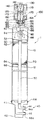
図1は本発明のレシーバドライヤの一実施例を示す断面図である。
全体を符号1で示すレシーバドライヤは、図示の下端部が開口する有底の中空の本体10を有する。この本体10は、例えばアルミ合金の素材を冷間鍛造加工により細長い有底円筒形に成形されるものである。アルミ合金は加工性が良いので、例えば底部より図示の上端側に延長して設けられるボス部20も一体に形成することができる。
FIG. 1 is a sectional view showing an embodiment of a receiver dryer according to the present invention.
Whole receiver drier shown by reference number 1, comprises a
このボス部20は、本体10の外径寸法よりも狭い寸法にて形成されて、材料の節約と軽量化を図る。本体10の開口部にはアルミ合金製の封止部材40がアーク溶接加工部AWにより溶接固着される。
The
封止部材40は、円盤形状の封止部41と、封止部41から突出する一体に形成された角柱状の取付部42とを有し、取付部42には冷媒の流入路44と冷媒の流出路46がそれぞれL字形状に設けられ、これらの端部(突出部)44a、46aは封止部材40から外方に向けて突出するパイプ状に形成されている。
The sealing
また、取付部42に形成される有底のボルト穴を利用して、レシーバドライヤ1は他の機器に固着される。この際に、パイプ状の端部44a,46aを相手の機器に挿入することにより、相手の機器への連結を簡略化することができる。
冷媒の流入路44に連通する封止部材40の開口部には、パイプ50の一端部が差し込まれ、パイプ50の他端部はパイプ支持部材80を介して本体10の内部の上端部に当接される。
Further, the receiver dryer 1 is fixed to another device using a bottomed bolt hole formed in the
One end of the
本体10の内部には、1対のフィルタ62,64により乾燥室が画成され、乾燥剤70が充填される。上部のフィルタ62の上面には、第1の押え板60が配設されてフィルタ62を支持する。この押え板60は、例えばメッシュ状の金属板等でつくられる。
第1の押え板60は、本体内に装備されるパイプ50に形成されるリング状の膨出部52により本体10内に位置決めされる。
Inside the
The
下部のフィルタ64は、第2の押え板66で下側を支持される。この第2の押え板66は、本体10の内側に突出する突起12により本体10内部に位置決めされる。突起12は、円周上の3ヵ所に設けられる。この突起をノッチ加工により形成することにかえて、ローリング加工により内側に突出する溝を用いることもできる。
The
パイプ支持部材80は、例えば合成樹脂を成形加工してつくられるものであって、パイプの取付部84と、着座部82を有する。
パイプ50から流入する冷媒は、スリット88を介して本体10内に注入される。
The
The refrigerant flowing from the
ボス部20には、リリーフ弁として機能する電磁弁100が取付けられる。
電磁弁100は、パイプ部材150の外周に電磁コイル120を有する。パイプ部材150の上部には、吸引子140が溶接により固定され、電磁コイル120を保持するケース130がビス142を介して吸引子140に固定される。
A
The
パイプ部材150の下端部は、ボス部20の開口部に挿入され、リング状の押圧部材160を介してボス部20の上端にカシメ部K1を形成することにより固着される。パイプ部材150の下端部にフランジ部を形成して、確実な固着を達成し、また、押圧部材160の下にシール部材162を挿入してシールを確実にする。さらに、押圧部材160の上には弾性部材164を挿入してケース130との接触を防止する。
The lower end of the
パイプ部材150の内部には、プランジャ170が摺動自在に挿入される。プランジャ170と吸引子140の間には、スプリング172が挿入され、プランジャ170を押圧する。
プランジャ170の先端には、弁体174が取付けられる。この弁体174は、プラスチック等の弾性材でつくられ、弁座180に対して常時当接する。
A
A
レシーバドライヤの本体10内に連通する通路182は、弁室184に冷媒を導入する。
一方、弁室184は、弁座180、通路186を介して大気側へ連通する。弁座180は、常時はプランジャ170の弁体174で閉鎖されていて、レシーバドライヤ内の冷媒は大気側へ漏れることはない。
A
On the other hand, the
カーエアコンを装備した自動車が衝突等を起こすと、衝撃を検知したセンサからの信号により、コイル120に通電される。コイル120が発生する磁力を受け、吸引子140は、スプリング172に抗してプランジャ170を吸引する。
プランジャ170の移動により、弁体174は弁座180から離れ、レシーバドライヤ1内の冷媒は、通路182、弁室184、通路186を通って大気側へ放出される。
When a car equipped with a car air conditioner causes a collision or the like, the
By movement of the
以上の説明においては、冷媒の流入路44と流出路46をL字形状に形成される場合について述べたが、本発明はこれに限らず、取付部に垂直に形成してもよいのは勿論である。
In the above description, the case where the
図2は、図1における本体10と封止部40との相互の関係とは異なる態様の構成を示し、他の構成は図1と同一であるので、説明を省略した図であり、取付部41には流入路44と流出路46とがいずれも垂直方向つまり本体10の軸線方向に対して互いに平行に形成されているのである。なお、流出路46は、そのパイプ50との間の接続部が上記軸線方向に対して直交する横孔に形成され、該横孔は、封止栓43で封止されている。
Figure 2 shows the configuration of a mode different from the mutual relationship between the
さらに上述したセンサに限らず、異常圧力や異常温度をセンサにより検知し、その検知信号でコイル20に通路してもよいのは勿論である。
Further, not only the above-described sensor, but also abnormal pressure and abnormal temperature may be detected by the sensor, and the detection signal may be passed to the
1 レシーバドライヤ
10 本体
12 内側へ突出するノッチ加工部
20 ボス部
40 封止部材
41 封止部
42 取付部
44 冷媒流入路
46 冷媒流出路
50 パイプ
60 上部押え板
62 上部フィルタ
64 下部フィルタ
66 下部押え板
80 パイプ支持部材
100 電磁弁
120 コイル
140 吸引子
150 パイプ部材
170 プランジャ
180 弁座
184 弁室
DESCRIPTION OF SYMBOLS 1
Claims (5)
前記電磁弁は、自動車が衝突等を起こした際の衝撃を検知するセンサーからの信号によりリリーフ動作をするように構成されていることを特徴とするレシーバドライヤ。 A receiver dryer that is installed in a refrigeration cycle of an automotive air conditioner and temporarily stores liquid phase refrigerant and removes moisture and foreign matters in the refrigerant, and includes a hollow main body that stores the refrigerant, and a refrigerant that flows through the refrigeration cycle An inflow path having an inflow port for allowing the refrigerant to flow into the main body, an outflow path having an outflow port for allowing the refrigerant in the main body to flow out toward the refrigeration cycle, and a passage for releasing the refrigerant in the main body into the outside air, In a receiver dryer comprising an electromagnetic valve for opening and closing the passage ,
The receiver dryer according to claim 1, wherein the solenoid valve is configured to perform a relief operation by a signal from a sensor that detects an impact when the automobile has a collision or the like .
Priority Applications (2)
| Application Number | Priority Date | Filing Date | Title |
|---|---|---|---|
| JP2003396968A JP4322099B2 (en) | 2003-11-27 | 2003-11-27 | Receiver dryer with relief valve |
| US10/995,108 US7322210B2 (en) | 2003-11-27 | 2004-11-24 | Receiver drier with relief valve |
Applications Claiming Priority (1)
| Application Number | Priority Date | Filing Date | Title |
|---|---|---|---|
| JP2003396968A JP4322099B2 (en) | 2003-11-27 | 2003-11-27 | Receiver dryer with relief valve |
Publications (3)
| Publication Number | Publication Date |
|---|---|
| JP2005153773A JP2005153773A (en) | 2005-06-16 |
| JP2005153773A5 JP2005153773A5 (en) | 2006-12-21 |
| JP4322099B2 true JP4322099B2 (en) | 2009-08-26 |
Family
ID=34616511
Family Applications (1)
| Application Number | Title | Priority Date | Filing Date |
|---|---|---|---|
| JP2003396968A Expired - Fee Related JP4322099B2 (en) | 2003-11-27 | 2003-11-27 | Receiver dryer with relief valve |
Country Status (2)
| Country | Link |
|---|---|
| US (1) | US7322210B2 (en) |
| JP (1) | JP4322099B2 (en) |
Families Citing this family (8)
| Publication number | Priority date | Publication date | Assignee | Title |
|---|---|---|---|---|
| JP2008215727A (en) * | 2007-03-05 | 2008-09-18 | Denso Corp | Refrigerant container and accumulator |
| US7730735B2 (en) * | 2007-05-22 | 2010-06-08 | Maruya Richard H | Refrigerant service port valve for air conditioners |
| CN201852383U (en) | 2010-11-17 | 2011-06-01 | 浙江三花汽车控制系统有限公司 | Heat exchanger and liquid storing device thereof |
| DE102013206357A1 (en) * | 2013-04-11 | 2014-10-16 | Behr Gmbh & Co. Kg | collector |
| CN104006589B (en) * | 2014-06-21 | 2016-01-20 | 吉首大学 | Novel ammonia refrigeration air separator |
| EP3228486B1 (en) | 2016-04-06 | 2020-05-06 | Lg Electronics Inc. | Safety device for vehicle |
| KR101855833B1 (en) * | 2016-04-06 | 2018-06-20 | 엘지전자 주식회사 | Safety device for vehicle |
| JP7372556B2 (en) * | 2021-09-30 | 2023-11-01 | ダイキン工業株式会社 | Refrigerant containers and refrigeration cycle equipment |
Family Cites Families (4)
| Publication number | Priority date | Publication date | Assignee | Title |
|---|---|---|---|---|
| US5252939A (en) * | 1992-09-25 | 1993-10-12 | Parker Hannifin Corporation | Low friction solenoid actuator and valve |
| JP3409193B2 (en) | 1993-12-28 | 2003-05-26 | 昭和電工株式会社 | Liquid receiver |
| US5868002A (en) * | 1996-07-29 | 1999-02-09 | Showa Aluminum Corporation | Condenser with a liquid-receiver |
| US5915665A (en) * | 1997-10-27 | 1999-06-29 | Kohler Co. | Latching solenoid valve |
-
2003
- 2003-11-27 JP JP2003396968A patent/JP4322099B2/en not_active Expired - Fee Related
-
2004
- 2004-11-24 US US10/995,108 patent/US7322210B2/en not_active Expired - Fee Related
Also Published As
| Publication number | Publication date |
|---|---|
| US20050115270A1 (en) | 2005-06-02 |
| US7322210B2 (en) | 2008-01-29 |
| JP2005153773A (en) | 2005-06-16 |
Similar Documents
| Publication | Publication Date | Title |
|---|---|---|
| KR100757284B1 (en) | Piston pump | |
| JP3026971B2 (en) | Combination of pressure sensor and high pressure relief valve for compressor | |
| JP4322099B2 (en) | Receiver dryer with relief valve | |
| CN102177057B (en) | Solenoid valve | |
| US4388196A (en) | Filter with heat controlled fluid flow bypass | |
| KR20010042195A (en) | Automotive evaporative leak detection system | |
| JP4255807B2 (en) | Expansion valve with electromagnetic relief valve | |
| JPH04503560A (en) | Self-locking gas spring with temperature-sensitive bypass valve | |
| US7691163B2 (en) | Vehicle air dryer | |
| JP2005316956A (en) | Pressure reducing valve | |
| EP1048541A1 (en) | Air desiccant canister | |
| US20190092305A1 (en) | Solenoid valve for brake system | |
| JP2000233638A (en) | Safety device for vehicle air conditioning system | |
| US5915669A (en) | Electromagnetic valve having a valve body with a sealing bead | |
| KR20070035939A (en) | Pilot solenoid valve | |
| JP2005537187A (en) | Solenoid valve | |
| US5613477A (en) | Evaporative fuel treatment device | |
| CN106764001B (en) | Air by-pass valve | |
| US20070057572A1 (en) | Hydraulic vehicle brake equipped with a parking brake device and method for its operation | |
| JP5251928B2 (en) | Vehicle collision detection device | |
| JPH09203351A (en) | Exhaust gas recycling device | |
| JPH11139285A (en) | Reservoir of hydraulic unit in vehicular brake device | |
| JPH06137726A (en) | Mounting layout of high and low pressure switch and fusible plug for car air conditioning device | |
| US20070114840A1 (en) | Piston-type accumulator | |
| US6449978B2 (en) | Air-conditioning refrigerant receiver |
Legal Events
| Date | Code | Title | Description |
|---|---|---|---|
| A521 | Request for written amendment filed |
Free format text: JAPANESE INTERMEDIATE CODE: A523 Effective date: 20061108 |
|
| A621 | Written request for application examination |
Free format text: JAPANESE INTERMEDIATE CODE: A621 Effective date: 20061108 |
|
| A977 | Report on retrieval |
Free format text: JAPANESE INTERMEDIATE CODE: A971007 Effective date: 20090220 |
|
| A131 | Notification of reasons for refusal |
Free format text: JAPANESE INTERMEDIATE CODE: A131 Effective date: 20090303 |
|
| A521 | Request for written amendment filed |
Free format text: JAPANESE INTERMEDIATE CODE: A523 Effective date: 20090428 |
|
| TRDD | Decision of grant or rejection written | ||
| A01 | Written decision to grant a patent or to grant a registration (utility model) |
Free format text: JAPANESE INTERMEDIATE CODE: A01 Effective date: 20090602 |
|
| A01 | Written decision to grant a patent or to grant a registration (utility model) |
Free format text: JAPANESE INTERMEDIATE CODE: A01 |
|
| A61 | First payment of annual fees (during grant procedure) |
Free format text: JAPANESE INTERMEDIATE CODE: A61 Effective date: 20090602 |
|
| R150 | Certificate of patent or registration of utility model |
Ref document number: 4322099 Country of ref document: JP Free format text: JAPANESE INTERMEDIATE CODE: R150 Free format text: JAPANESE INTERMEDIATE CODE: R150 |
|
| FPAY | Renewal fee payment (event date is renewal date of database) |
Free format text: PAYMENT UNTIL: 20120612 Year of fee payment: 3 |
|
| FPAY | Renewal fee payment (event date is renewal date of database) |
Free format text: PAYMENT UNTIL: 20120612 Year of fee payment: 3 |
|
| FPAY | Renewal fee payment (event date is renewal date of database) |
Free format text: PAYMENT UNTIL: 20130612 Year of fee payment: 4 |
|
| R250 | Receipt of annual fees |
Free format text: JAPANESE INTERMEDIATE CODE: R250 |
|
| R250 | Receipt of annual fees |
Free format text: JAPANESE INTERMEDIATE CODE: R250 |
|
| R250 | Receipt of annual fees |
Free format text: JAPANESE INTERMEDIATE CODE: R250 |
|
| R250 | Receipt of annual fees |
Free format text: JAPANESE INTERMEDIATE CODE: R250 |
|
| R250 | Receipt of annual fees |
Free format text: JAPANESE INTERMEDIATE CODE: R250 |
|
| R250 | Receipt of annual fees |
Free format text: JAPANESE INTERMEDIATE CODE: R250 |
|
| R250 | Receipt of annual fees |
Free format text: JAPANESE INTERMEDIATE CODE: R250 |
|
| R250 | Receipt of annual fees |
Free format text: JAPANESE INTERMEDIATE CODE: R250 |
|
| R250 | Receipt of annual fees |
Free format text: JAPANESE INTERMEDIATE CODE: R250 |
|
| LAPS | Cancellation because of no payment of annual fees |