WO2020184858A1 - 스티어 바이 와이어용 조향장치 - Google Patents
스티어 바이 와이어용 조향장치 Download PDFInfo
- Publication number
- WO2020184858A1 WO2020184858A1 PCT/KR2020/002229 KR2020002229W WO2020184858A1 WO 2020184858 A1 WO2020184858 A1 WO 2020184858A1 KR 2020002229 W KR2020002229 W KR 2020002229W WO 2020184858 A1 WO2020184858 A1 WO 2020184858A1
- Authority
- WO
- WIPO (PCT)
- Prior art keywords
- steering
- steer
- wire
- disk
- gear
- Prior art date
- Legal status (The legal status is an assumption and is not a legal conclusion. Google has not performed a legal analysis and makes no representation as to the accuracy of the status listed.)
- Ceased
Links
Images


Classifications
-
- B—PERFORMING OPERATIONS; TRANSPORTING
- B62—LAND VEHICLES FOR TRAVELLING OTHERWISE THAN ON RAILS
- B62D—MOTOR VEHICLES; TRAILERS
- B62D5/00—Power-assisted or power-driven steering
- B62D5/001—Mechanical components or aspects of steer-by-wire systems, not otherwise provided for in this maingroup
-
- B—PERFORMING OPERATIONS; TRANSPORTING
- B62—LAND VEHICLES FOR TRAVELLING OTHERWISE THAN ON RAILS
- B62D—MOTOR VEHICLES; TRAILERS
- B62D5/00—Power-assisted or power-driven steering
- B62D5/001—Mechanical components or aspects of steer-by-wire systems, not otherwise provided for in this maingroup
- B62D5/005—Mechanical components or aspects of steer-by-wire systems, not otherwise provided for in this maingroup means for generating torque on steering wheel or input member, e.g. feedback
-
- B—PERFORMING OPERATIONS; TRANSPORTING
- B62—LAND VEHICLES FOR TRAVELLING OTHERWISE THAN ON RAILS
- B62D—MOTOR VEHICLES; TRAILERS
- B62D5/00—Power-assisted or power-driven steering
- B62D5/04—Power-assisted or power-driven steering electrical, e.g. using an electric servo-motor connected to, or forming part of, the steering gear
- B62D5/0409—Electric motor acting on the steering column
-
- B—PERFORMING OPERATIONS; TRANSPORTING
- B62—LAND VEHICLES FOR TRAVELLING OTHERWISE THAN ON RAILS
- B62D—MOTOR VEHICLES; TRAILERS
- B62D5/00—Power-assisted or power-driven steering
- B62D5/04—Power-assisted or power-driven steering electrical, e.g. using an electric servo-motor connected to, or forming part of, the steering gear
- B62D5/0457—Power-assisted or power-driven steering electrical, e.g. using an electric servo-motor connected to, or forming part of, the steering gear characterised by control features of the drive means as such
- B62D5/046—Controlling the motor
-
- B—PERFORMING OPERATIONS; TRANSPORTING
- B62—LAND VEHICLES FOR TRAVELLING OTHERWISE THAN ON RAILS
- B62D—MOTOR VEHICLES; TRAILERS
- B62D5/00—Power-assisted or power-driven steering
- B62D5/001—Mechanical components or aspects of steer-by-wire systems, not otherwise provided for in this maingroup
- B62D5/005—Mechanical components or aspects of steer-by-wire systems, not otherwise provided for in this maingroup means for generating torque on steering wheel or input member, e.g. feedback
- B62D5/006—Mechanical components or aspects of steer-by-wire systems, not otherwise provided for in this maingroup means for generating torque on steering wheel or input member, e.g. feedback power actuated
Definitions
- the present embodiments relate to a steering device for a steer-by-wire, and more specifically, a torque due to friction is applied when the steering shaft is rotated to provide a sense of weight to the driver's steering wheel operation, and the wheel can no longer rotate, such as being caught on a curb.
- the present invention relates to a steering device for a steer-by-wire capable of improving a driver's steering feeling and steering stability by limiting rotation of a steering shaft in a situation.
- a steer-by-wire type steering device is a type of electric steering device, and refers to a device that uses electrical power to steer a vehicle without mechanical connection such as a steering column or universal joint between the steering wheel and the front wheel steering device.
- the steering wheel operation of the driver is converted into an electric signal, which is inputted from the electronic control device, and the motor output is determined accordingly.
- This steer-by-wire system does not have a mechanical connection, so the driver injury due to the mechanical part in the event of a collision. It reduces the number of components and reduces the number of mechanical connections and hydraulic parts, so it improves fuel economy by reducing unnecessary energy consumption during steering operation by reducing the number of parts and simplifying the vehicle weight reduction and rapid reduction in line assembly work. In addition, it is possible to achieve ideal steering performance by programming the ECU.
- a first gear meshed with a gear portion provided on an outer circumferential surface of a steering shaft a second gear meshed with a first gear on an inner circumferential surface, and a disk coaxially provided with the steering shaft and rotated in conjunction with the first gear
- a fixed frame provided with a pair of supports spaced apart in the width direction, a drive frame facing one side of the disk and slidable in the axial direction between the support parts, and an actuator for sliding the drive frame.
- a steering device for a steer-by-wire including a may be provided.
- torque is applied by friction when the steering shaft is rotated to provide a sense of weight to the driver's steering wheel operation, and by limiting the rotation of the steering shaft in a situation where the wheel can no longer rotate, such as being caught on the curb, the driver It can improve the steering feel and steering stability.
- FIG. 1 is an exploded perspective view of a steering device for a steer-by-wire according to the present embodiments.
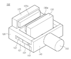
- Figure 2 is a perspective view of the combined state of Figure 1;
- FIG. 3 is a perspective view of a part of FIG. 1.
- Figure 4 is a perspective view of the combined state of Figure 3;
- 5 to 6 are cross-sectional views of FIG. 2.
- first, second, A, B, (a), (b) may be used. These terms are only used to distinguish the component from other components, and the nature, order, or order of the component is not limited by the term.
- a component is described as being “connected”, “coupled” or “connected” to another component, the component may be directly connected or connected to that other component, but another component between each component It should be understood that elements may be “connected”, “coupled” or “connected”.
- FIG. 1 is an exploded perspective view of a steering device for a steer-by-wire according to the present embodiments
- FIG. 2 is a perspective view of a combined state of FIG. 1
- FIG. 3 is a perspective view of a part of FIG. 1
- FIG. 4 is a combined state of FIG.
- a perspective view of, FIGS. 5 to 6 are cross-sectional views of FIG. 2.
- the steering apparatus 100 for a steer-by-wire includes a first gear 102 meshing with a gear unit 101a provided on the outer circumferential surface of the steering shaft 101, and a first gear 102 on the inner circumferential surface. Is provided with a second gear 103 that meshes, a disk 105 that is provided coaxially with the steering shaft 101 and rotates in connection with the first gear 102, and a pair of support portions 121 spaced apart in the width direction
- the fixed frame 120 which is opposed to one side of the disk 105 and is provided to be slidable in the axial direction between the support portion 121, the drive frame 130, the actuator 150 for sliding the drive frame 130 It includes a rotation limiting device 106 is provided.
- the steering shaft 101 is connected to the steering wheel and rotates by the driver's steering wheel manipulation.
- the steering shaft 101 is equipped with a torque sensor, a rotation angle sensor, etc., so that the driver's steering wheel manipulation is converted into an electric signal, Is rotated.
- the steering shaft 101 is provided with a reaction force motor and a stopper, and the reaction force motor is controlled by an electronic control device so that a torque in the direction opposite to the rotation direction of the steering shaft 101 is applied to the steering shaft 101.
- the stopper limits the rotation of the steering wheel and the steering shaft 101 when the rotation of the steering wheel reaches a maximum.
- Such a stopper includes, for example, a pair of plates spaced apart in the axial direction and fixed to the vehicle body and a nut that slides in the axial direction by rotation of the steering shaft, and the nut is supported on the plate and rotates. It may be provided to limit, therefore, the rotation of the steering shaft 101 can be limited only when the rotation of the steering wheel reaches the maximum, so that the wheel cannot be rotated even if the steering wheel is not rotated to the maximum, for example When the wheel is caught on the curb, etc., rotation of the steering wheel cannot be restricted.
- the steering device 100 for a steer-by-wire includes the rotation limiting device 106 and the steering shaft ( 101) can be limited.
- a gear part 101a is formed on the outer circumferential surface of the steering shaft 101, and the first gear 102 meshes with the gear part 101a and is supported by the steering shaft 101.
- the second gear 103 having a gear formed on the inner circumferential surface meshes with the first gear 102.
- the first gear 102 is spaced apart in the circumferential direction and may be provided with a plurality, and the drawing shows an embodiment in which three first gears 102 are provided.
- the first gear 102 is engaged with the inner circumferential surface of the second gear 103, that is, the first gear 102 is provided between the outer circumferential surface of the steering shaft 101 and the inner circumferential surface of the second gear 103.
- the second gear 103 is fixed to the vehicle body, so when the steering shaft 101 is rotated, the second gear 103 is not rotated, and the first gear 102 is the central axis of the first gear 102 And it is rotated based on the central axis of the steering shaft 101.
- the second gear 103 is formed in a ring shape, but is not limited thereto, and may be formed integrally with a housing and a gear formed on an inner peripheral surface of the housing.
- the disk 105 is provided coaxially with the steering shaft 101 and rotates in conjunction with the first gear 102, in other words, is interlocked with the first gear 102 rotated based on the central axis of the steering shaft 101 Rotated.
- a first hole 111 into which the steering shaft 101 is inserted is formed in the disk 105, and the inner diameter of the disk 105 may be formed larger than the outer diameter of the steering shaft 101.
- the disk 105 since the disk 105 is rotated in conjunction with the first gear 102, the speed at which the disk 105 is rotated by the gear ratio is different from the speed at which the steering shaft 101 is rotated, so the steering shaft 101 is rotated.
- the inner diameter of the disk 105 In order to prevent friction between the outer peripheral surface of the steering shaft 101 and the inner peripheral surface of the disk 105, the inner diameter of the disk 105 needs to be formed larger than the outer diameter of the steering shaft 101.
- the disk 105 may be coupled to the steering shaft 101 via a bearing.
- the disk 105 may be provided with a connection shaft 104 to rotate in conjunction with the first gear 102, that is, the first gear 102 is provided with a connection shaft 104 protruding in the axial direction.
- a second hole 112 into which an end of the connection shaft 104 is inserted may be formed in the disk 105.
- the second holes 112 may be spaced apart in the circumferential direction from the outer periphery of the first hole 111 and may be formed in plural.
- the connecting shaft 104 may be manufactured as a separate object from the first gear 102 and coupled to the first gear 102 by press fitting or the like, or manufactured integrally with the first gear 102 It may be.
- the disk 105 and the connection shaft 104 may be coupled via a bearing 113, as shown in the figure, the bearing 113 is coupled to the second hole 112 and the connection shaft 104 Silver may be provided to be coupled to the inner ring of the bearing 113.
- first gear 102 and the connecting shaft 104 are rotated not only about the central axis of the steering shaft 101 but also about the central axis of the first gear 102, the end of the connecting shaft 104 and the disk ( The bearing 113 needs to be provided to prevent friction from occurring between 105).
- the connecting shaft 104 may be formed integrally with the disk 105 and the opposite end portion may be provided to be coupled to the first gear 102 and the bearing as a medium.
- the disk 105 rotates together with the steering shaft 101.
- the rotation limiting device 106 is attached to the disk 105. By creating friction, it is possible to limit the rotation of the steering wheel in any situation.
- the disk 105 is coupled to the steering shaft 101 by the first gear 102, the second gear 103 and the connection shaft 104, the wear or damage of the gear teeth can be prevented and stability can be improved. have.
- the disk 105 it is difficult to form the disk 105 integrally with the steering shaft 101 and it is difficult to assemble with other parts, so the disk 105 needs to be manufactured separately from the steering shaft 101.
- the rotation limiting device 106 may limit the rotation of the steering wheel, but in such a case, the torque applied to the gear or spline is It is too large and there is a risk that the gear teeth are easily worn or damaged.
- the disk 105 is coupled to the steering shaft 101 by the first gear 102 or the like, so that the torque due to friction applied by the rotation limiting device 106 to the disk 105 is dispersed, so that stability can be improved. .
- the rotation limiting device 106 includes a fixed frame 120, a driving frame 130, and an actuator 150, and a pair of the fixed frame 120 is spaced apart in the width direction.
- the supporting part 121 of the is provided, and the driving frame 130 is opposite to one side of the disk 105 and is slidably coupled between the supporting parts 121 in the axial direction, and the driving frame is driven by the actuator 150
- the 130 slides in the axial direction and is supported or spaced apart from the disk 105.
- the fixing frame 120 is fixed to the vehicle body, although not shown in the drawing, the fixing frame 120 may be coupled to the vehicle body by a bracket or the like.
- the actuator 150 is controlled by an electronic control device provided in the vehicle, and the electronic control device controls the actuator 150 in a situation where the wheel can no longer rotate, such as being caught on a curb, so that the drive frame 130 105) and limit the rotation of the steering wheel by generating friction.
- the driving frame 130 may be provided with a friction pad 120a supported on the disk 105, and as will be described later, a friction pad may also be provided on the protrusion 123 provided on the fixed frame 120. (130a) may be provided.
- the fixed frame 120 may be provided with a protrusion 123 that faces the other side of the disk 105, and the protrusion 123 is provided so that a part of the disk 105 is provided with the fixed frame 120 and the driving frame 130 ) Is inserted between.
- the protrusion 123 may be provided to be supported on the disk 105, and as described above, the friction pad 130a may be supported on the other side of the disk 105.
- the fixed frame 120 is fixed to the vehicle body and supported on the other side of the disk 105, regardless of whether the actuator 150 is operated or not.
- friction is generated on the disk 105 so that the driver feels a steering feeling when operating the steering wheel.
- the support 121 is provided with a slide groove 122 that is elongated in the axial direction, and the driving frame 130 has slide protrusions 131 inserted into the slide groove 122 on both sides in the width direction, The sliding of the driving frame 130 is guided by the groove 122 and the slide protrusion 131.
- the slide groove 122 is opened in the axial direction, the slide protrusion 131 is inserted into the slide groove 122 and the driving frame 130 may be coupled to the fixed frame 120.
- the slide groove 122 is also opened in the width direction is shown, but is not limited thereto.
- the rotation limiting device 106 may include a cover member 140 that is axially coupled to the support portion 121, that is, after the drive frame 130 is coupled to the fixing frame 120, the cover member 140 ) Is coupled to the support portion 121 and prevents the driving frame 130 from being separated from the fixed frame 120.
- the cover member 140 may be provided with an insertion protrusion 141 inserted into the slide groove 122 to be coupled to the support portion 121, and may be coupled by screwing or the like.
- the drive frame 130 may be provided with a through hole 132 penetrating in the axial direction
- the actuator 150 may be provided with a rotation shaft 151 inserted into the through hole 132, the rotation of the rotation shaft 151 By this, the driving frame 130 is slid in the axial direction.
- a motor may be used as the actuator 150.
- a screw part is formed on the outer circumferential surface of the rotation shaft 151 and the through hole 132 so that the drive frame 130 and the rotation shaft are screwed, and the rotation shaft 151 is rotated by the operation of the actuator 150, and The driving frame 130 is slid.
- the rotation shaft 151 is coupled to the driving frame 130, such as an insertion hole 142 and an insertion groove 311 It needs to be equipped.
- one of the fixing frame 120 and the cover member 140 is provided with an insertion hole 142 through which the rotation shaft 151 is inserted through the axial direction, and the end of the rotation shaft 151 is inserted in the other.
- Insertion groove 311 may be provided.
- bearings 143 and 312 are provided in the insertion hole 142 and the insertion groove 311 so that the rotation shaft 151 can smoothly rotate, so that both ends of the rotation shaft 151 are fixed frame 120 and cover member 140. It may be coupled through the bearings (143, 312).
- the slide protrusion 131 is inserted into the slide groove 122, the fixing frame 120 and the driving frame 130 are coupled, and the cover member 140 is a slide groove.
- 122 is closed and coupled to the support 121, the rotation shaft 151 is inserted into the insertion hole 142, the through hole 132, and the insertion groove 311, and the actuator 150 may be coupled.
- the disk is coupled to the steering shaft via the first gear, the second gear, and the connecting shaft, so that when the rotation limiting device applies friction to the disk, torque is dispersed and the gear teeth are worn. It is prevented from being damaged or broken, so that the stability can be improved.
Landscapes
- Engineering & Computer Science (AREA)
- Chemical & Material Sciences (AREA)
- Combustion & Propulsion (AREA)
- Transportation (AREA)
- Mechanical Engineering (AREA)
- Power Steering Mechanism (AREA)
- Steering Control In Accordance With Driving Conditions (AREA)
Abstract
본 실시예들에 의하면, 조향축 회전 시 마찰에 의한 토크를 가하여 운전자의 조향휠 조작에 무게감을 제공하고, 바퀴가 연석에 걸리는 등 더이상 회전될 수 없는 임의의 상황에서 조향축이 회전되는 것을 제한하여 운전자의 조향감과 조향안정성을 향상시킬 수 있다.
Description
본 실시예들은 스티어 바이 와이어용 조향장치에 관한 것으로, 보다 상세하게는 조향축 회전 시 마찰에 의한 토크를 가하여 운전자의 조향휠 조작에 무게감을 제공하고, 바퀴가 연석에 걸리는 등 더이상 회전될 수 없는 상황에서 조향축이 회전되는 것을 제한하여 운전자의 조향감과 조향안정성을 향상시킬 수 있는 스티어 바이 와이어용 조향장치에 관한 것이다.
스티어 바이 와이어식 조향장치란 일종의 전동식 조향장치로서, 조향휠과 전륜 조향장치 사이에 조향컬럼, 유니버셜 조인트 등 기계적인 연결 없이 전기적인 동력을 이용하여 차량을 조타시키는 장치를 말한다.
즉, 운전자의 조향휠 조작이 전기 신호로 변환되어 전자제어장치에서 이를 입력받게 되고 그에 따라 모터의 출력이 결정되게 되는데, 이러한 스티어 바이 와이어식 시스템은 기계적인 연결이 없으므로 충돌 시 기구부에 의한 운전자 상해를 감소시키며 기계적 연결 및 유압부품 삭감이 가능하므로 부품수 축소로 차량의 경량화 및 라인 조립공수 급감 등의 단순화로 조향 작동 시의 불필요한 에너지 소모를 줄임으로서 연비를 향상시킨다. 또한, ECU 프로그래밍에 의하여 이상적인 조향 성능 달성이 가능하다.
종래 스티어 바이 와이어식 조향장치의 경우 조향축과 바퀴와의 기계적인 연결이 없기 때문에 노면에서 바퀴의 마찰, 걸림 등에 의한 무게감이 운전자에게 전달되지 않아 조향감이 저하되는 문제가 있었으며, 또한 바퀴가 연석에 걸리는 등 더 이상 회전될 수 없음에도 조향휠이 회전될 수 있는 문제가 있었다.
본 실시예들은 전술한 배경에서 안출된 것으로, 조향축 회전 시 마찰에 의한 토크를 가하여 운전자의 조향휠 조작에 무게감을 제공하고, 바퀴가 연석에 걸리는 등 더 이상 회전될 수 없는 상황에서 조향축이 회전되는 것을 제한하여 운전자의 조향감과 조향안정성을 향상시킬 수 있는 것을 목적으로 한다.
본 실시예들의 목적은 여기에 제한되지 않으며, 언급되지 않은 또 다른 목적들은 아래의 기재로부터 통상의 기술자에게 명확하게 이해될 수 있을 것이다.
본 실시예들에 의하면, 조향축의 외주면에 구비되는 기어부와 맞물리는 제 1 기어, 내주면에 제 1 기어가 맞물리는 제 2 기어, 조향축과 동축으로 구비되고 제 1 기어와 연동되어 회전되는 디스크, 폭방향으로 이격되는 한 쌍의 지지부가 구비되는 고정프레임, 디스크의 일측면과 대향되고 지지부의 사이에서 축방향으로 슬라이딩 가능하게 구비되는 구동프레임, 구동프레임을 슬라이딩시키는 액추에이터가 구비되는 회전제한장치를 포함하는 스티어 바이 와이어용 조향장치가 제공될 수 있다.
본 실시예들에 의하면, 조향축 회전 시 마찰에 의한 토크를 가하여 운전자의 조향휠 조작에 무게감을 제공하고, 바퀴가 연석에 걸리는 등 더이상 회전될 수 없는 상황에서 조향축이 회전되는 것을 제한하여 운전자의 조향감과 조향안정성을 향상시킬 수 있다.
도 1은 본 실시예들에 의한 스티어 바이 와이어용 조향장치의 분해사시도이다.
도 2는 도 1의 결합상태에 대한 사시도이다.
도 3은 도 1의 일부에 대한 사시도이다.
도 4는 도 3의 결합상태에 대한 사시도이다.
도 5 내지 도 6은 도 2의 단면도이다.
이하, 본 실시예들의 일부 실시예들을 예시적인 도면을 통해 상세하게 설명한다. 각 도면의 구성요소들에 참조부호를 부가함에 있어서, 동일한 구성요소들에 대해서는 비록 다른 도면상에 표시되더라도 가능한 한 동일한 부호를 가지도록 하고 있음에 유의해야 한다. 또한, 본 실시예들을 설명함에 있어, 관련된 공지 구성 또는 기능에 대한 구체적인 설명이 본 실시예들의 요지를 흐릴 수 있다고 판단되는 경우에는 그 상세한 설명은 생략한다.
또한, 본 실시예들의 구성 요소를 설명하는 데 있어서, 제 1, 제 2, A, B, (a), (b) 등의 용어를 사용할 수 있다. 이러한 용어는 그 구성 요소를 다른 구성 요소와 구별하기 위한 것일 뿐, 그 용어에 의해 해당 구성 요소의 본질이나 차례 또는 순서 등이 한정되지 않는다. 어떤 구성 요소가 다른 구성요소에 "연결", "결합" 또는 "접속"된다고 기재된 경우, 그 구성 요소는 그 다른 구성요소에 직접적으로 연결되거나 또는 접속될 수 있지만, 각 구성 요소 사이에 또 다른 구성 요소가 "연결", "결합" 또는 "접속"될 수도 있다고 이해되어야 할 것이다.
도 1은 본 실시예들에 의한 스티어 바이 와이어용 조향장치의 분해사시도, 도 2는 도 1의 결합상태에 대한 사시도, 도 3은 도 1의 일부에 대한 사시도, 도 4는 도 3의 결합상태에 대한 사시도, 도 5 내지 도 6은 도 2의 단면도이다.
본 실시예들에 의한 스티어 바이 와이어용 조향장치(100)는, 조향축(101)의 외주면에 구비되는 기어부(101a)와 맞물리는 제 1 기어(102), 내주면에 제 1 기어(102)가 맞물리는 제 2 기어(103), 조향축(101)과 동축으로 구비되고 제 1 기어(102)와 연동되어 회전되는 디스크(105), 폭방향으로 이격되는 한 쌍의 지지부(121)가 구비되는 고정프레임(120), 디스크(105)의 일측면과 대향되고 지지부(121)의 사이에서 축방향으로 슬라이딩 가능하게 구비되는 구동프레임(130), 구동프레임(130)을 슬라이딩시키는 액추에이터(150)가 구비되는 회전제한장치(106)를 포함한다.
조향축(101)은 조향휠과 연결되어 운전자의 조향휠 조작에 의해 회전되는데, 조향축(101)에는 토크센서, 회전각센서 등이 구비되어 있어 운전자의 조향휠 조작이 전기신호로 변환되어 바퀴가 회전되게 된다.
도면에는 도시되지 않았으나 조향축(101)에는 반력모터와 스토퍼가 구비되어 있는데, 반력모터는 전자제어장치에 의해 제어되어 조향축(101)에 조향축(101)의 회전방향과 반대방향의 토크를 가하며, 스토퍼는 조향휠의 회전이 최대에 도달할 때 조향휠 및 조향축(101)의 회전을 제한한다.
이러한 스토퍼는, 예를 들어, 축방향으로 이격되며 차체에 고정되는 한 쌍의 플레이트와 플레이트의 사이에 구비되며 조향축의 회전에 의해 축방향으로 슬라이딩되는 너트를 포함하여 너트가 플레이트에 지지되며 회전을 제한하도록 구비될 수 있는데, 따라서 조향휠의 회전이 최대에 도달하는 경우에만 조향축(101)의 회전을 제한할 수 있어 조향휠이 최대로 회전되지 않더라도 바퀴가 회전될 수 없는 경우, 예를 들어 바퀴가 연석에 걸리는 경우 등에는 조향휠의 회전을 제한할 수 없는데, 본 실시예들에 의한 스티어 바이 와이어용 조향장치(100)는 회전제한장치(106)를 포함하여 임의의 상황에서 조향축(101)의 회전을 제한할 수 있게 된다.
도 1 내지 도 2을 참고하여 살펴보면, 조향축(101)의 외주면에는 기어부(101a)가 형성되어 있고, 제 1 기어(102)는 기어부(101a)와 맞물리며 조향축(101)에 지지되며, 내주면에 기어가 형성된 제 2 기어(103)가 제 1 기어(102)와 맞물린다.
제 1 기어(102)는 원주방향으로 이격되며 복수개 구비될 수 있는데, 도면에는 제 1 기어(102)가 세 개 구비되는 실시예가 도시되어 있다.
제 2 기어(103)의 내주면에는 제 1 기어(102)가 맞물리게 되며, 다시 말해 제 1 기어(102)는 조향축(101)의 외주면과 제 2 기어(103)의 내주면 사이에 구비되게 된다.
제 2 기어(103)는 차체에 고정되게 되는데, 따라서 조향축(101)이 회전될 때 제 2 기어(103)는 회전되지 않고, 제 1 기어(102)가 제 1 기어(102)의 중심축 및 조향축(101)의 중심축을 기준으로 회전되게 된다.
도면에는 편의상 제 2 기어(103)가 링형상으로 형성되는 실시예가 도시되어 있는데 반드시 이에 한정되는 것은 아니며, 하우징과 일체로 형성되고 하우징의 내주면에 기어가 형성되는 것일 수도 있다.
디스크(105)는 조향축(101)과 동축으로 구비되되 제 1 기어(102)와 연동되어 회전되는데, 다시 말해 조향축(101)의 중심축을 기준으로 회전되는 제 1 기어(102)와 연동되어 회전된다.
디스크(105)에는 조향축(101)이 삽입되는 제 1 홀(111)이 형성되어 있는데, 디스크(105)의 내경은 조향축(101)의 외경보다 크게 형성될 수 있다.
즉, 디스크(105)는 제 1 기어(102)와 연동되어 회전되므로 기어비에 의해 디스크(105)가 회전되는 속도는 조향축(101)이 회전되는 속도와 다르므로, 조향축(101)이 회전될 때 조향축(101)의 외주면과 디스크(105)의 내주면 사이에서 마찰이 발생되는 것을 방지하기 위해 디스크(105)의 내경이 조향축(101)의 외경보다 크게 형성될 필요가 있다.
도면에는 도시되지 않았으나, 디스크(105)는 조향축(101)에 베어링을 매개로 결합될 수도 있을 것이다.
또한, 디스크(105)가 제 1 기어(102)와 연동되어 회전되기 위해 연결축(104)이 구비될 수 있는데, 즉 제 1 기어(102)에는 축방향으로 돌출되는 연결축(104)이 구비되고, 디스크(105)에는 연결축(104)의 단부가 삽입되는 제 2 홀(112)이 형성될 수 있다.
도면에 도시된 바와 같이, 제 2 홀(112)은 제 1 홀(111)의 외곽에서 원주방향으로 이격되며 복수개 형성될 수 있다.
연결축(104)은 도면에 도시된 바와 같이 제 1 기어(102)와 별물로 제작되어 제 1 기어(102)에 압입 등에 의해 결합되는 것일 수 있으며, 또는 제 1 기어(102)와 일체로 제작되는 것일 수도 있다.
그리고, 디스크(105)와 연결축(104)은 베어링(113)을 매개로 결합될 수 있는데, 도면에 도시된 바와 같이 제 2 홀(112)에 베어링(113)이 결합되고 연결축(104)은 베어링(113)의 내륜에 결합되게 구비될 수 있다.
즉, 제 1 기어(102)와 연결축(104)은 조향축(101)의 중심축뿐만 아니라 제 1 기어(102)의 중심축을 기준으로도 회전되므로, 연결축(104)의 단부와 디스크(105) 사이에서 마찰이 발생되는 것을 방지하기 위해 베어링(113)이 구비될 필요가 있다.
도면에는 도시되지 않았으나, 연결축(104)은 디스크(105)와 일체로 형성되고 반대측단부가 제 1 기어(102)와 베어링을 매개로 결합되게 구비될 수도 있을 것이다.
이상에서 설명한 바와 같이, 운전자의 조향휠 조작 시 조향축(101)과 함께 디스크(105)가 회전되게 되는데, 바퀴가 연석에 걸리는 경우 등이 발생할 때 회전제한장치(106)가 디스크(105)에 마찰을 발생시킴으로써 임의의 상황에서 조향휠의 회전을 제한할 수 있다.
또한, 디스크(105)가 제 1 기어(102), 제 2 기어(103) 및 연결축(104)에 의해 조향축(101)과 결합됨으로써, 기어치의 마모나 파손이 방지되며 안정성이 향상될 수 있다.
즉, 디스크(105)를 조향축(101)과 일체로 형성하는 것은 제작하기 어렵고 또한 다른 부품과의 조립이 어려워 디스크(105)는 조향축(101)과 별물로 제작될 필요가 있으며, 별물로 제작되는 디스크(105)가 조향축(101)에 기어 또는 스플라인 등에 의해 결합되는 경우에도 회전제한장치(106)에 의해 조향휠의 회전을 제한할 수 있을 것이나 그러한 경우 기어 또는 스플라인에 가해지는 토크가 지나치게 커서 기어치 등이 쉽게 마모되거나 파손될 위험이 있다.
따라서, 제 1 기어(102) 등에 의해 디스크(105)가 조향축(101)과 결합됨으로써 회전제한장치(106)가 디스크(105)에 가하는 마찰에 의한 토크가 분산되어 안정성이 향상될 수 있는 것이다.
도 3 내지 도 6를 참고하여 살펴보면, 회전제한장치(106)는 고정프레임(120), 구동프레임(130) 및 액추에이터(150)를 포함하는데, 고정프레임(120)에는 폭방향으로 이격되는 한 쌍의 지지부(121)가 구비되어 있으며, 구동프레임(130)은 디스크(105)의 일측면과 대향되며 지지부(121)의 사이에서 축방향으로 슬라이딩 가능하게 결합되어, 액추에이터(150)에 의해 구동프레임(130)이 축방향으로 슬라이딩되며 디스크(105)에 지지되거나 이격되게 된다.
고정프레임(120)은 차체에 고정되는데, 도면에는 도시되지 않았으나 고정프레임(120)은 브라켓 등에 의해 차체에 결합될 수 있다.
액추에이터(150)는 차량에 구비되는 전자제어장치에 의해 제어되며, 바퀴가 연석에 걸리는 등 더 이상 회전될 수 없는 상황에서 전자제어장치가 액추에이터(150)를 제어하여 구동프레임(130)이 디스크(105)에 지지되며 마찰을 발생시킴으로써 조향휠의 회전을 제한하게 된다.
도면에 도시된 바와 같이, 구동프레임(130)에는 디스크(105)에 지지되는 마찰패드(120a)가 구비될 수 있으며, 후술할 바와 같이 고정프레임(120)에 구비되는 돌출부(123)에도 마찰패드(130a)가 구비될 수 있다.
고정프레임(120)에는 디스크(105)의 타측면과 대향되는 돌출부(123)가 구비될 수 있는데, 돌출부(123)가 구비됨으로써 디스크(105)는 일부가 고정프레임(120)과 구동프레임(130)의 사이에 삽입되어 있는 형태를 취하게 된다.
이러한 돌출부(123)는 디스크(105)에 지지되게 구비될 수 있는데, 전술한 바와 같이 마찰패드(130a)가 디스크(105)의 타측면에 지지될 수 있다.
즉, 액추에이터(150)에 의해 축방향으로 슬라이딩되는 구동프레임(130)과 달리, 고정프레임(120)은 차체에 고정되며 디스크(105)의 타측면에 지지됨으로써 액추에이터(150)의 작동여부와 무관하게 디스크(105)에 마찰을 발생시켜 운전자가 조향휠을 조작할 때 조향감을 느끼게 할 수 있다.
또한, 액추에이터(150)에 의해 구동프레임(130)이 디스크(105)의 일측면에 지지될 때 디스크(105)의 타측면이 돌출부(123)에 지지됨으로써, 디스크(105)의 양측면이 지지되게 되므로 구조적으로 안정성이 향상되며 마찰력이 상승될 수 있다.
이어서, 지지부(121)에는 축방향으로 길게 형성되는 슬라이드홈(122)이 구비되고, 구동프레임(130)에는 슬라이드홈(122)에 삽입되는 슬라이드돌기(131)가 폭방향 양측에 구비되어, 슬라이드홈(122)과 슬라이드돌기(131)에 의해 구동프레임(130)의 슬라이딩이 가이드된다.
이러한 슬라이드홈(122)은 축방향으로 개구되어, 슬라이드돌기(131)가 슬라이드홈(122)에 삽입되며 구동프레임(130)이 고정프레임(120)에 결합될 수 있다. 도면에는 슬라이드홈(122)이 폭방향으로도 개구되는 실시예가 도시되어 있는데, 반드시 이에 한정되는 것은 아니다.
또한, 회전제한장치(106)는 지지부(121)에 축방향으로 결합되는 커버부재(140)를 포함할 수 있는데, 즉 구동프레임(130)이 고정프레임(120)에 결합된 후 커버부재(140)가 지지부(121)에 결합되며 구동프레임(130)이 고정프레임(120)에서 이탈되는 것을 방지한다.
커버부재(140)에는 슬라이드홈(122)에 삽입되는 삽입돌기(141)가 구비되어 지지부(121)에 결합될 수 있으며, 나사결합 등에 의해서도 결합될 수 있을 것이다.
또한, 구동프레임(130)에는 축방향으로 관통되는 관통홀(132)이 구비되고 액추에이터(150)에는 관통홀(132)에 삽입되는 회전축(151)이 구비될 수 있는데, 회전축(151)의 회전에 의해 구동프레임(130)이 축방향으로 슬라이딩되게 된다. 액추에이터(150)로는 모터가 사용될 수 있다.
즉, 회전축(151)의 외주면 및 관통홀(132)에 나사부가 형성되어 구동프레임(130)과 회전축이 나사결합되고, 액추에이터(150)의 작동에 의해 회전축(151)이 회전되며 나사결합에 의해 구동프레임(130)의 슬라이딩되는 것이다.
구동프레임(130)의 폭방향 양측에 구비되는 슬라이드돌기(131)가 슬라이드홈(122)에 삽입되어 지지부(121)에 의해 원주방향으로 지지되게 되므로, 회전축(151)이 회전되더라도 구동프레임(130)은 회전되지 않으며 축방향으로만 슬라이딩될 수 있다.
구동프레임(130)은 고정프레임(120)과 커버부재(140)의 사이에 구비되어 있으므로, 회전축(151)이 구동프레임(130)과 결합되기 위해서 삽입홀(142) 및 삽입홈(311) 등이 구비될 필요가 있다.
즉, 고정프레임(120)과 커버부재(140) 중 어느 하나에는 축방향으로 관통되어 회전축(151)이 삽입되는 삽입홀(142)이 구비되고, 다른 하나에는 회전축(151)의 단부가 삽입되는 삽입홈(311)이 구비될 수 있다.
도면에는 커버부재(140)에 삽입홀(142)이 구비되고 고정프레임(120)에 삽입홈(311)이 구비되는 실시예가 도시되어 있으며, 이와 반대로 구비될 수 있음은 당연하다.
그리고, 회전축(151)이 원활히 회전될 수 있도록, 삽입홀(142)과 삽입홈(311)에 베어링(143,312)이 구비됨으로써 회전축(151)의 양단부가 고정프레임(120)과 커버부재(140)에 베어링(143,312)을 매개로 결합될 수 있다.
회전제한장치(106)가 조립되는 방식을 살펴보면, 슬라이드홈(122)에 슬라이드돌기(131)가 삽입되며 고정프레임(120)과 구동프레임(130)이 결합되고, 커버부재(140)가 슬라이드홈(122)을 폐쇄하며 지지부(121)에 결합되고, 회전축(151)이 삽입홀(142), 관통홀(132) 및 삽입홈(311)에 삽입되며 액추에이터(150)가 결합될 수 있을 것이다.
이와 같은 형상을 가지는 스티어 바이 와이어용 조향장치에 의하면, 디스크가 제 1 기어, 제 2 기어 및 연결축을 매개로 조향축에 결합됨으로써 회전제한장치가 디스크에 마찰을 가할 때 토크가 분산되어 기어치가 마모되거나 파손되는 것이 방지되어 안정성이 향상될 수 있다.
또한, 고정프레임의 돌출부가 디스크의 타측면에 지지됨으로써 조향축 회전시 마찰에 의한 토크를 가하여 운전자의 조향휠 조작에 무게감을 제공하여 조향감을 향상시킬 수 있다.
또한, 바퀴가 연석에 걸리는 등 더이상 회전될 수 없는 임의의 상황에서 조향축이 회전되는 것을 제한하여 운전자의 조향감과 조향안정성을 향상시킬 수 있다.
이상에서, 본 실시예들의 실시예를 구성하는 모든 구성 요소들이 하나로 결합되거나 결합되어 동작하는 것으로 설명되었다고 해서, 본 실시예들이 반드시 이러한 실시예에 한정되는 것은 아니다. 즉, 본 실시예들의 목적 범위 안에서라면, 그 모든 구성 요소들이 하나 이상으로 선택적으로 결합하여 동작할 수도 있다.
또한, 이상에서 기재된 "포함하다", "구성하다" 또는 "가지다" 등의 용어는, 특별히 반대되는 기재가 없는 한, 해당 구성 요소가 내재될 수 있음을 의미하는 것이므로, 다른 구성 요소를 제외하는 것이 아니라 다른 구성 요소를 더 포함할 수 있는 것으로 해석되어야 한다. 기술적이거나 과학적인 용어를 포함한 모든 용어들은, 다르게 정의되지 않는 한, 본 실시예들이 속하는 기술 분야에서 통상의 지식을 가진 자에 의해 일반적으로 이해되는 것과 동일한 의미를 가진다. 사전에 정의된 용어와 같이 일반적으로 사용되는 용어들은 관련 기술의 문맥 상의 의미와 일치하는 것으로 해석되어야 하며, 본 실시예들에서 명백하게 정의하지 않는 한, 이상적이거나 과도하게 형식적인 의미로 해석되지 않는다.
이상의 설명은 본 실시예들의 기술 사상을 예시적으로 설명한 것에 불과한 것으로서, 본 실시예들이 속하는 기술 분야에서 통상의 지식을 가진 자라면 본 실시예들의 본질적인 특성에서 벗어나지 않는 범위에서 다양한 수정 및 변형이 가능할 것이다. 따라서, 본 실시예들에 개시된 실시예들은 본 실시예들의 기술 사상을 한정하기 위한 것이 아니라 설명하기 위한 것이고, 이러한 실시예에 의하여 본 실시예들의 기술 사상의 범위가 한정되는 것은 아니다. 본 실시예들의 보호 범위는 아래의 청구범위에 의하여 해석되어야 하며, 그와 동등한 범위 내에 있는 모든 기술 사상은 본 실시예들의 권리범위에 포함되는 것으로 해석되어야 할 것이다.
CROSS-REFERENCE TO RELATED APPLICATION
본 특허출원은 2019년 03월 14일 한국에 출원한 특허출원번호 제 10-2019-0029548 호에 대해 미국 특허법 119(a)조 (35 U.S.C § 119(a))에 따라 우선권을 주장하며, 그 모든 내용은 참고문헌으로 본 특허출원에 병합된다. 아울러, 본 특허출원은 미국 이외에 국가에 대해서도 위와 동일한 이유로 우선권을 주장하면 그 모든 내용은 참고문헌으로 본 특허출원에 병합된다.
Claims (16)
- 조향축의 외주면에 구비되는 기어부와 맞물리는 제 1 기어;내주면에 상기 제 1 기어가 맞물리는 제 2 기어;상기 조향축과 동축으로 구비되고 상기 제 1 기어와 연동되어 회전되는 디스크;폭방향으로 이격되는 한 쌍의 지지부가 구비되는 고정프레임, 상기 디스크의 일측면과 대향되고 상기 지지부의 사이에서 축방향으로 슬라이딩 가능하게 구비되는 구동프레임, 상기 구동프레임을 슬라이딩시키는 액추에이터가 구비되는 회전제한장치;를 포함하는 스티어 바이 와이어용 조향장치.
- 제 1 항에 있어서,상기 디스크에는 상기 조향축이 삽입되는 제 1 홀이 형성되는 것을 특징으로 하는 스티어 바이 와이어용 조향장치.
- 제 2 항에 있어서,상기 디스크의 내경은 상기 조향축의 외경보다 크게 형성되는 것을 특징으로 하는 스티어 바이 와이어용 조향장치.
- 제 2 항에 있어서,상기 제 1 기어에는 축방향으로 돌출되는 연결축이 구비되고, 상기 디스크에는 상기 연결축의 단부가 삽입되는 제 2 홀이 형성되는 것을 특징으로 하는 스티어 바이 와이어용 조향장치.
- 제 4 항에 있어서,상기 디스크와 연결축은 베어링을 매개로 결합되는 것을 특징으로 하는 스티어 바이 와이어용 조향장치.
- 제 1 항에 있어서,상기 고정프레임에는 상기 디스크의 타측면과 대향되는 돌출부가 구비되는 것을 특징으로 하는 스티어 바이 와이어용 조향장치.
- 제 6 항에 있어서,상기 돌출부는 상기 디스크에 지지되는 것을 특징으로 하는 스티어 바이 와이어용 조향장치.
- 제 1 항에 있어서,상기 지지부에는 축방향으로 길게 형성되는 슬라이드홈이 구비되고, 상기 구동프레임에는 상기 슬라이드홈에 삽입되는 슬라이드돌기가 폭방향 양측에 구비되는 것을 특징으로 하는 스티어 바이 와이어용 조향장치.
- 제 8 항에 있어서,상기 슬라이드홈은 축방향으로 개구되는 것을 특징으로 하는 스티어 바이 와이어용 조향장치.
- 제 9 항에 있어서,상기 회전제한장치는 상기 지지부에 축방향으로 결합되는 커버부재를 포함하는 것을 특징으로 하는 스티어 바이 와이어용 조향장치.
- 제 10 항에 있어서,상기 커버부재에는 상기 슬라이드홈에 삽입되는 삽입돌기가 구비되는 것을 특징으로 하는 스티어 바이 와이어용 조향장치.
- 제 10 항에 있어서,상기 구동프레임에는 축방향으로 관통되는 관통홀이 구비되고 상기 액추에이터에는 상기 관통홀에 삽입되는 회전축이 구비되는 것을 특징으로 하는 스티어 바이 와이어용 조향장치.
- 제 12 항에 있어서,상기 구동프레임과 회전축은 나사결합되는 것을 특징으로 하는 스티어 바이 와이어용 조향장치.
- 제 12 항에 있어서,상기 고정프레임과 커버부재 중 어느 하나에는 축방향으로 관통되어 상기 회전축이 삽입되는 삽입홀이 구비되는 것을 특징으로 하는 스티어 바이 와이어용 조향장치.
- 제 14 항에 있어서,상기 고정프레임과 커버부재 중 다른 하나에는 상기 회전축의 단부가 삽입되는 삽입홈이 구비되는 것을 특징으로 하는 스티어 바이 와이어용 조향장치.
- 제 15 항에 있어서,상기 회전축은 양단부가 상기 고정프레임과 커버부재에 베어링을 매개로 결합되는 것을 특징으로 하는 스티어 바이 와이어용 조향장치.
Priority Applications (3)
| Application Number | Priority Date | Filing Date | Title |
|---|---|---|---|
| US17/438,933 US12151749B2 (en) | 2019-03-14 | 2020-02-17 | Steering system for steer-by-wire |
| DE112020001235.2T DE112020001235T5 (de) | 2019-03-14 | 2020-02-17 | Steer-by-wire lenksystem |
| CN202080021287.XA CN113573969B (zh) | 2019-03-14 | 2020-02-17 | 用于线控转向的转向系统 |
Applications Claiming Priority (2)
| Application Number | Priority Date | Filing Date | Title |
|---|---|---|---|
| KR1020190029548A KR102167450B1 (ko) | 2019-03-14 | 2019-03-14 | 스티어 바이 와이어용 조향장치 |
| KR10-2019-0029548 | 2019-03-14 |
Publications (1)
| Publication Number | Publication Date |
|---|---|
| WO2020184858A1 true WO2020184858A1 (ko) | 2020-09-17 |
Family
ID=72427465
Family Applications (1)
| Application Number | Title | Priority Date | Filing Date |
|---|---|---|---|
| PCT/KR2020/002229 Ceased WO2020184858A1 (ko) | 2019-03-14 | 2020-02-17 | 스티어 바이 와이어용 조향장치 |
Country Status (5)
| Country | Link |
|---|---|
| US (1) | US12151749B2 (ko) |
| KR (1) | KR102167450B1 (ko) |
| CN (1) | CN113573969B (ko) |
| DE (1) | DE112020001235T5 (ko) |
| WO (1) | WO2020184858A1 (ko) |
Cited By (1)
| Publication number | Priority date | Publication date | Assignee | Title |
|---|---|---|---|---|
| US11511791B2 (en) * | 2019-12-06 | 2022-11-29 | Steering Solutions Ip Holding Corporation | Cantilevered worm gear assembly with brake bushing |
Families Citing this family (1)
| Publication number | Priority date | Publication date | Assignee | Title |
|---|---|---|---|---|
| KR102792227B1 (ko) * | 2020-05-26 | 2025-04-07 | 현대자동차주식회사 | Sbw시스템의 조향반력 보조장치 |
Citations (5)
| Publication number | Priority date | Publication date | Assignee | Title |
|---|---|---|---|---|
| US20050145433A1 (en) * | 2004-01-07 | 2005-07-07 | Honda Motor Co., Ltd. | Apparatus for steering a vehicle |
| KR20100047522A (ko) * | 2008-10-29 | 2010-05-10 | 주식회사 윈텍 | 전기 자동차용 파워 트레인 모듈 |
| JP2012035738A (ja) * | 2010-08-06 | 2012-02-23 | Ntn Corp | ステアバイワイヤ式操舵装置の反力トルクアクチュエータ |
| KR20140042746A (ko) * | 2012-09-28 | 2014-04-07 | 히다치 오토모티브 시스템즈 가부시키가이샤 | 디스크 브레이크 장치 |
| US20180362079A1 (en) * | 2017-06-20 | 2018-12-20 | GM Global Technology Operations LLC | Steering column feel emulator mechanical stops |
Family Cites Families (22)
| Publication number | Priority date | Publication date | Assignee | Title |
|---|---|---|---|---|
| US4009641A (en) * | 1975-11-14 | 1977-03-01 | General Motors Corporation | Compact power steering gear |
| DE4031616C2 (de) * | 1990-10-05 | 1999-11-25 | Perrot Bremse Gmbh Deutsche | Automatische Nachstelleinrichtung für eine mechanisch betätigte Gleitsattel-Scheibenbremse |
| JP3772997B2 (ja) | 1995-07-31 | 2006-05-10 | 住友電装株式会社 | 電気自動車用充電システム及び電気自動車充電用電磁結合装置 |
| GB9520616D0 (en) | 1995-10-09 | 1995-12-13 | Lucas Ind Plc | Improvements in electrically-operated disc brake assemblies for vehicles |
| JP3681912B2 (ja) | 1999-01-26 | 2005-08-10 | 光洋精工株式会社 | 電動パワーステアリング装置 |
| US6481526B1 (en) * | 2000-11-13 | 2002-11-19 | Delphi Technologies, Inc. | Steer-by-wire handwheel actuator incorporating mechanism for variable end-of-travel |
| JP2004249934A (ja) * | 2003-02-21 | 2004-09-09 | Nissan Motor Co Ltd | 車両用操舵装置 |
| JP2007112397A (ja) * | 2005-10-24 | 2007-05-10 | Toyota Motor Corp | 車両の操舵装置 |
| JP2008285045A (ja) * | 2007-05-18 | 2008-11-27 | Mitsuba Corp | 車両用制御装置 |
| KR101208367B1 (ko) | 2008-03-07 | 2012-12-05 | 주식회사 만도 | 차량용 디스크 브레이크 |
| JP5233738B2 (ja) * | 2009-02-25 | 2013-07-10 | 日産自動車株式会社 | 車両用操舵装置、車両用操舵装置付き車両 |
| KR20110124818A (ko) * | 2010-05-12 | 2011-11-18 | 주식회사 만도 | 전동식 디스크브레이크 |
| JP5943628B2 (ja) * | 2011-04-13 | 2016-07-05 | 日立オートモティブシステムズ株式会社 | ディスクブレーキ |
| JP6432239B2 (ja) | 2014-09-19 | 2018-12-05 | アイシン精機株式会社 | 車両の後輪操舵装置 |
| DE112016004477T5 (de) | 2015-10-02 | 2018-06-14 | Hitachi Automotive Systems, Ltd. | Methode zum Herstellen einer Gewindewelle für eine Servolenkungs-Vorrichtung, und eine Servolenkungs-Vorrichtung |
| KR101816396B1 (ko) * | 2016-05-03 | 2018-02-21 | 현대자동차주식회사 | 전동식 브레이크 |
| KR102657328B1 (ko) * | 2016-11-23 | 2024-04-15 | 현대자동차주식회사 | 스티어 바이 와이어 시스템용 조향장치 |
| CN206653859U (zh) | 2017-05-02 | 2017-11-21 | 齐齐哈尔市北方牧业机械一厂 | 一种原地零半径的转向驱动桥 |
| KR102642206B1 (ko) * | 2018-09-12 | 2024-03-04 | 엘지이노텍 주식회사 | 모터 |
| DE102019202294A1 (de) * | 2019-02-20 | 2020-08-20 | Ford Global Technologies, Llc | Lenkbegrenzungsvorrichtung, Steer-by-Wire-Lenksystem und Fahrzeug |
| KR101998766B1 (ko) | 2019-03-11 | 2019-07-10 | 엘지이노텍 주식회사 | 발광소자 패키지 |
| KR102786792B1 (ko) * | 2020-08-25 | 2025-03-31 | 에이치엘만도 주식회사 | 스티어 바이 와이어식 조향장치 |
-
2019
- 2019-03-14 KR KR1020190029548A patent/KR102167450B1/ko active Active
-
2020
- 2020-02-17 DE DE112020001235.2T patent/DE112020001235T5/de active Pending
- 2020-02-17 US US17/438,933 patent/US12151749B2/en active Active
- 2020-02-17 CN CN202080021287.XA patent/CN113573969B/zh active Active
- 2020-02-17 WO PCT/KR2020/002229 patent/WO2020184858A1/ko not_active Ceased
Patent Citations (5)
| Publication number | Priority date | Publication date | Assignee | Title |
|---|---|---|---|---|
| US20050145433A1 (en) * | 2004-01-07 | 2005-07-07 | Honda Motor Co., Ltd. | Apparatus for steering a vehicle |
| KR20100047522A (ko) * | 2008-10-29 | 2010-05-10 | 주식회사 윈텍 | 전기 자동차용 파워 트레인 모듈 |
| JP2012035738A (ja) * | 2010-08-06 | 2012-02-23 | Ntn Corp | ステアバイワイヤ式操舵装置の反力トルクアクチュエータ |
| KR20140042746A (ko) * | 2012-09-28 | 2014-04-07 | 히다치 오토모티브 시스템즈 가부시키가이샤 | 디스크 브레이크 장치 |
| US20180362079A1 (en) * | 2017-06-20 | 2018-12-20 | GM Global Technology Operations LLC | Steering column feel emulator mechanical stops |
Cited By (1)
| Publication number | Priority date | Publication date | Assignee | Title |
|---|---|---|---|---|
| US11511791B2 (en) * | 2019-12-06 | 2022-11-29 | Steering Solutions Ip Holding Corporation | Cantilevered worm gear assembly with brake bushing |
Also Published As
| Publication number | Publication date |
|---|---|
| US20220153337A1 (en) | 2022-05-19 |
| US12151749B2 (en) | 2024-11-26 |
| CN113573969A (zh) | 2021-10-29 |
| KR20200109828A (ko) | 2020-09-23 |
| CN113573969B (zh) | 2024-05-10 |
| KR102167450B1 (ko) | 2020-10-19 |
| DE112020001235T5 (de) | 2021-12-16 |
Similar Documents
| Publication | Publication Date | Title |
|---|---|---|
| WO2020256426A1 (ko) | 스티어 바이 와이어식 조향장치 | |
| WO2021091194A1 (ko) | 스티어 바이 와이어식 조향장치 | |
| WO2020256336A1 (ko) | 스티어 바이 와이어식 조향장치 | |
| WO2021162441A1 (ko) | 스티어 바이 와이어식 조향장치 | |
| WO2020184883A1 (ko) | 스티어 바이 와이어식 조향장치 | |
| WO2021049803A1 (ko) | 자동차의 조향컬럼 | |
| WO2020231114A1 (ko) | 자동차의 조향장치 | |
| WO2020184858A1 (ko) | 스티어 바이 와이어용 조향장치 | |
| WO2011129509A1 (ko) | 전동 파워스티어링 장치 | |
| WO2021054681A1 (ko) | 스티어 바이 와이어식 조향장치 | |
| JPH04506646A (ja) | 駆動系統を接続する装置 | |
| JP2001080385A (ja) | 駆動力切換機構 | |
| IL266120B (en) | Driving configuration | |
| WO2020231111A1 (ko) | 자동차 조향장치 | |
| KR20220088482A (ko) | 조향 시스템 및 차량 | |
| WO2019124648A1 (ko) | 전동식 지게 차량의 싱글 드라이브 액슬 | |
| EP1239191B1 (en) | Differential unit | |
| WO2021091193A1 (ko) | 스티어 바이 와이어식 조향장치 | |
| EP1715219B1 (en) | Differential limiter | |
| WO2019231032A1 (ko) | 차량용 액추에이터 | |
| US8348009B2 (en) | Steering device, particularly electric servo steering device for a motor vehicle | |
| CN216478865U (zh) | 用于电动汽车的驻车锁止装置及电动汽车 | |
| WO2023172078A1 (ko) | 전자식 주차 브레이크 | |
| WO2021085945A1 (ko) | 스티어 바이 와이어식 조향장치 | |
| CN203078225U (zh) | 挖掘机转向驱动前桥 |
Legal Events
| Date | Code | Title | Description |
|---|---|---|---|
| 121 | Ep: the epo has been informed by wipo that ep was designated in this application |
Ref document number: 20770091 Country of ref document: EP Kind code of ref document: A1 |
|
| 122 | Ep: pct application non-entry in european phase |
Ref document number: 20770091 Country of ref document: EP Kind code of ref document: A1 |