WO2020184422A1 - 切削インサート、切削工具及び切削加工物の製造方法 - Google Patents
切削インサート、切削工具及び切削加工物の製造方法 Download PDFInfo
- Publication number
- WO2020184422A1 WO2020184422A1 PCT/JP2020/009629 JP2020009629W WO2020184422A1 WO 2020184422 A1 WO2020184422 A1 WO 2020184422A1 JP 2020009629 W JP2020009629 W JP 2020009629W WO 2020184422 A1 WO2020184422 A1 WO 2020184422A1
- Authority
- WO
- WIPO (PCT)
- Prior art keywords
- region
- angle
- convex portion
- width
- cutting
- Prior art date
- Legal status (The legal status is an assumption and is not a legal conclusion. Google has not performed a legal analysis and makes no representation as to the accuracy of the status listed.)
- Ceased
Links
Images





Classifications
-
- B—PERFORMING OPERATIONS; TRANSPORTING
- B23—MACHINE TOOLS; METAL-WORKING NOT OTHERWISE PROVIDED FOR
- B23B—TURNING; BORING
- B23B27/00—Tools for turning or boring machines; Tools of a similar kind in general; Accessories therefor
- B23B27/14—Cutting tools of which the bits or tips or cutting inserts are of special material
- B23B27/16—Cutting tools of which the bits or tips or cutting inserts are of special material with exchangeable cutting bits or cutting inserts, e.g. able to be clamped
- B23B27/1603—Cutting tools of which the bits or tips or cutting inserts are of special material with exchangeable cutting bits or cutting inserts, e.g. able to be clamped with specially shaped plate-like exchangeable cutting inserts, e.g. chip-breaking groove
- B23B27/1611—Cutting tools of which the bits or tips or cutting inserts are of special material with exchangeable cutting bits or cutting inserts, e.g. able to be clamped with specially shaped plate-like exchangeable cutting inserts, e.g. chip-breaking groove characterised by having a special shape
-
- B—PERFORMING OPERATIONS; TRANSPORTING
- B23—MACHINE TOOLS; METAL-WORKING NOT OTHERWISE PROVIDED FOR
- B23B—TURNING; BORING
- B23B27/00—Tools for turning or boring machines; Tools of a similar kind in general; Accessories therefor
- B23B27/04—Cutting-off tools
-
- B—PERFORMING OPERATIONS; TRANSPORTING
- B23—MACHINE TOOLS; METAL-WORKING NOT OTHERWISE PROVIDED FOR
- B23B—TURNING; BORING
- B23B35/00—Methods for boring or drilling, or for working essentially requiring the use of boring or drilling machines; Use of auxiliary equipment in connection with such methods
Definitions
- This disclosure relates to cutting inserts used in cutting. Specifically, it relates to a cutting insert used for turning such as grooving.
- Patent Document 1 As a cutting insert used when turning a work material such as metal, for example, the cutting tip described in Japanese Patent Application Laid-Open No. 2011-520630 (Patent Document 1) is known.
- the cutting tip (cutting insert) described in Patent Document 1 has an upper surface, a lower surface, and a peripheral side surface.
- the peripheral side surface has a front end face and a rear end face.
- the lower surface has a restraining surface in the shape of a V-shaped groove extending along the central axis (vertical axis).
- the restraint surface has a first surface component located on the side of the front end face and a second surface component located on the side of the rear end face.
- the wedge angle of the second surface component is smaller than the wedge angle of the first surface component.
- the one-sided cutting insert of the present disclosure has an upper surface, a lower surface, a front surface and a rear surface.
- the lower surface is located on the opposite side of the upper surface.
- the front surface is located between the top and bottom surfaces.
- the rear side surface is between the upper surface and the lower surface and is located on the opposite side of the front side surface.
- the upper surface has a first upper blade and an upper restraint surface.
- the first upper blade is located at the intersection with the front side surface.
- the upper restraint surface is located closer to the rear side surface than the first upper blade and can come into contact with the holder.
- the lower surface has a lower restraint surface that can come into contact with the holder.
- the lower restraint surface has a downward convex portion extending from a region located near the front side surface toward the rear side surface.
- the downward convex portion has a first region, a second region, and a third region.
- the first region is located on the opposite side of the upper restraint surface.
- the second region is located on the front side surface side of the first region.
- the third region is located on the rear side surface side of the first region.
- the wedge angle of the first region is defined as the first angle
- the wedge angle of the second region is defined as the second angle
- the wedge angle of the third region is defined as the third angle.
- the first corner is smaller than the second and third corners.
- FIG. 5 is a plan view of the cutting insert shown in FIG. 1 as viewed from the lower surface side.
- FIG. 5 is a plan view of the cutting insert shown in FIG. 2 as viewed from the front side surface side.
- FIG. 5 is a plan view of the cutting insert shown in FIG. 2 as viewed from the rear side surface side.
- It is a side view which looked at the cutting insert shown in FIG. 2 from the A1 direction. It is sectional drawing of the VII-VII cross section in the cutting insert shown in FIG. It is sectional drawing of the VIII-VIII cross section in the cutting insert shown in FIG.
- the cutting insert 1 (hereinafter, also simply referred to as “insert 1”) of the non-limiting embodiment of the present disclosure will be described in detail with reference to the drawings.
- the insert 1 may include any component not shown in each referenced figure.
- the dimensions of the members in each drawing do not faithfully represent the dimensions of the actual constituent members and the dimensional ratio of each member.
- the insert 1 may have an upper surface 3, a lower surface 5, a front side surface 7, and a rear side surface 9.
- the lower surface 5 may be located on the opposite side of the upper surface 3.
- the front side surface 7 and the rear side surface 9 may be located between the upper surface 3 and the lower surface 5, respectively.
- the rear side surface 9 may be located on the opposite side of the front side surface 7.
- the front side surface 7 and the rear side surface 9 may be connected to the upper surface 3 and the lower surface 5, respectively.
- the upper surface 3 and the lower surface 5 are expressions for convenience and do not indicate the upward and downward directions.
- the top surface 3 does not have to be an upward facing surface when using the insert 1.
- the front side surface 7 and the rear side surface 9 are also expressions for convenience and do not indicate the front and rear directions.
- the insert 1 may have a first side surface 11 and a second side surface 13 in addition to the above-mentioned surfaces.
- the first side surface 11 and the second side surface 13 may be located between the upper surface 3 and the lower surface 5, and between the front side surface 7 and the rear side surface 9, respectively.
- the first side surface 11 and the second side surface 13 may be connected to the upper surface 3, the lower surface 5, the front side surface 7, and the rear side surface 9, respectively.
- the insert 1 may have a quadrangular prism shape having an upper surface 3, a lower surface 5, a front side surface 7, a rear side surface 9, a first side surface 11, and a second side surface 13, as in the case of the non-limiting example shown in FIG.
- the insert 1 may have a prismatic shape extending from the front end to the rear end along the central axis O1.
- the central axis O1 may be an axis passing through the center of the front side surface 7 and the center of the rear side surface 9.
- the front side surface 7 may be located at the tip end, and the rear side surface 9 may be located at the rear end.
- the front side surface 7 and the rear side surface 9 may be quadrangular, respectively, and the upper surface 3, the lower surface 5, the first side surface 11 and the first side surface 9 are directed from the front side surface 7 to the rear side surface 9.
- Each of the four surfaces of the two side surfaces 13 may extend.
- the upper surface 3, the lower surface 5, the front side surface 7, the rear side surface 9, the first side surface 11 and the second side surface 13 are not limited to specific sizes, respectively.
- the length of the upper surface 3 in the direction along the central axis O1 when the upper surface 3 is viewed from the front (when viewed from the top) may be set to about 3 to 50 mm.
- the length of the upper surface 3 in the direction orthogonal to the central axis O1 when viewed from the upper surface may be set to about 1.5 to 15 mm.
- the height of the insert 1 indicated by the distance between the upper surface 3 and the lower surface 5 may be set to about 2 to 20 mm.
- the upper surface 3 may have a first upper blade 15 and an upper restraint surface 17.
- the first upper blade 15 may be located at the intersection with the front side surface 7 on the upper surface 3.
- the first upper blade 15 may be located at the entire intersection of the upper surface 3 and the front side surface 7, or may be located only at a part of the intersection of the upper surface 3 and the front side surface 7.
- the first upper blade 15 may be used for cutting a work material.
- the first upper blade 15 in an example without limitation shown in FIG. 1 is generally also referred to as a front cutting blade or a main cutting blade.
- the upper restraint surface 17 may be located closer to the rear side surface 9 than the first upper blade 15.
- the upper restraint surface 17 can abut (contact) with the holder when the insert 1 is attached to the holder.
- the upper restraint surface 17 may include an intersection with the rear end side end portion of the upper surface 3, that is, the rear side surface 9, and may be separated from this intersection.
- the upper surface 3 may have a rake surface 19 located along the first upper blade 15.
- the rake face 19 may be connected to the upper restraint surface 17 or may be separated from the upper restraint surface 17. Further, the upper surface 3 may further have a second upper blade 21 in addition to the first upper blade 15 as a cutting blade.
- the second upper blade 21 may be located, for example, at the intersection with the first side surface 11 on the upper surface 3 or at the intersection with the second side surface 13 on the upper surface 3.
- the second upper blade 21 may be located at each of the intersection with the first side surface 11 on the upper surface 3 and the intersection with the second side surface 13 on the upper surface 3. ..
- the lower surface 5 may have a lower restraint surface 23.
- the lower restraint surface 23 may be located on the entire lower surface 5, or may be located only on a part of the lower surface 5.
- the lower restraint surface 23 can abut (contact) with the holder when the insert 1 is attached to the holder. By bringing the lower restraint surface 23 and the upper restraint surface 17 into contact with the holder, the insert 1 can be gripped by the holder.
- the lower restraint surface 23 may have a lower convex portion 25 extending from a region located near the front side surface 7 toward the rear side surface 9.
- the lower convex portion 25 may reach the front side surface 7 or may be separated from the front side surface 7.
- the lower convex portion 25 may reach the rear side surface 9 or may be separated from the rear side surface 9.
- the downward convex portion 25 may be separated from the front side surface 7 and the rear side surface 9.
- the downward convex portion 25 since the downward convex portion 25 extends from the front side surface 7 side toward the rear side surface 9 side, it may be paraphrased as extending parallel to the central axis O1.
- the downward convex portion 25 may have a convex shape in a cross section orthogonal to the extending direction, in other words, a cross section orthogonal to the central axis O1.
- the lower convex portion 25 may have a pair of inclined surfaces 27 whose spacing becomes wider as the distance from the top of the lower convex portion 25 increases. Therefore, for example, a convex curved surface 29 connecting the pair of inclined surfaces 27 may be located on the top of the downward convex portion 25.
- the downward convex portion 25 may have a first region 31, a second region 33, and a third region 35.
- the first region 31 may be located on the opposite side of the upper restraint surface 17.
- the second region 33 may be located closer to the front side surface 7 than the first region 31.
- the second region 33 may include an end of the lower convex portion 25 on the side of the front side surface 7, or may be separated from the front side surface 7.
- the third region 35 may be located closer to the rear side surface 9 than the first region 31.
- the third region 35 may include an end of the downward convex portion 25 on the side of the rear side surface 9, or may be separated from the rear side surface 9.
- the shapes of the first region 31, the second region 33, and the third region 35 in the cross section orthogonal to the extending direction of the downward convex portion 25, in other words, the cross section orthogonal to the central axis O1, may be compared. .. Specifically, in a cross section orthogonal to the extending direction of the downward convex portion 25, the wedge angle of the first region 31 is the first angle ⁇ 1, the wedge angle of the second region 33 is the second angle ⁇ 2, and the third region 35.
- the wedge angle may be the third angle ⁇ 3.
- the "wedge angle” in the above may mean an angle formed by a pair of inclined surfaces 27 in a cross section orthogonal to the central axis O1. That is, the wedge angle of the downward convex portion 25 in the cross section orthogonal to the central axis O1 and passing through the first region 31 may be the first angle ⁇ 1.
- the wedge angle of the downward convex portion 25 in the cross section orthogonal to the central axis O1 and passing through the second region 33 may be the second angle ⁇ 2.
- the wedge angle of the downward convex portion 25 in the cross section orthogonal to the central axis O1 and passing through the third region 35 may be the third angle ⁇ 3.
- the first angle ⁇ 1 may be smaller than the second angle ⁇ 2 and the third angle ⁇ 3. In this case, the durability of the insert 1 is high. Since the first angle ⁇ 1 is relatively small, the position of the insert 1 is unlikely to shift in the direction orthogonal to the central axis O1 when viewed from above.
- the main component force applied to the insert 1 during cutting is applied to the second region 33 located on the front side surface 7 side and the rear side surface 9. It is easy to catch in the third area 35 located on the side. Since the main component force is easily received in the second region 33 and the third region 35, it is difficult for the main component force to be applied to the first region 31 located between these regions. Therefore, the durability of the insert 1 is high.
- the first angle ⁇ 1, the second angle ⁇ 2, and the third angle ⁇ 3 are not limited to specific values.
- the first angle ⁇ 1 may be set to, for example, 100 ° to 140 °.
- the second angle ⁇ 2 may be set to, for example, 120 ° to 160 °.
- the third angle ⁇ 3 may be set to, for example, 120 ° to 160 °.
- the first angle ⁇ 1, the second angle ⁇ 2, and the third angle ⁇ 3 may be constant or may change, respectively.
- the first angle ⁇ 1 may change
- the second angle ⁇ 2 and the third angle ⁇ 3 may be constant.
- the first portion 37 is located on the side of the front side surface 7 and the wedge angle (first angle ⁇ 1) becomes smaller as the first region 31 approaches the rear side surface 9, and the side of the rear side surface 9. It may have a second portion 39, which is located at the position of and whose wedge angle (first angle ⁇ 1) becomes smaller as it approaches the front side surface 7.
- the first portion 37 may be located on the front side surface 7 side of the center of the first region 31 in the extending direction of the lower convex portion 25.
- the second portion 39 may be located on the rear side surface 9 side of the center of the first region 31 in the extending direction of the lower convex portion 25.
- the wedge angle (first angle ⁇ 1) may be constant in the portion located between the first portion 37 and the second portion 39 and including the center of the first region 31.
- the first region 31 has the first portion 37 described above, it is easy to avoid a sudden change in the wedge angle at the boundary between the first region 31 and the second region 33. Further, when the first region 31 has the second portion 39 described above, it is easy to avoid a sudden change in the wedge angle at the boundary between the first region 31 and the third region 35. Therefore, the durability of the insert 1 is even higher.
- the second angle ⁇ 2 is constant
- the pair of inclined surfaces 27 in the second region 33 have a planar shape. Therefore, the second region 33 easily comes into surface contact with the holder.
- the third angle ⁇ 3 is constant
- the pair of inclined surfaces 27 in the third region 35 have a planar shape. Therefore, the third region 35 easily comes into surface contact with the holder. In this case, the above-mentioned main component force is more easily received in the second region 33 and the third region 35.
- the maximum values of the respective maximum values may be compared.
- the second angle ⁇ 2 may be the same as the third angle ⁇ 3, or may be different from the third angle ⁇ 3. As in the non-limiting example shown in FIGS. 8 and 9, the second angle ⁇ 2 may be smaller than the third angle ⁇ 3.
- the second region 33 may be located closer to the front surface 7 as compared to the first region 31 and the third region 35. That is, the second region 33 may be located closer to the first upper blade 15 as compared with the first region 31 and the third region 35.
- the upper restraint surface 17 may have an upper convex portion 41 extending from a region located near the front side surface 7 toward the rear side surface 9.
- the upper convex portion 41 may reach the front side surface 7 or may be separated from the front side surface 7.
- the upper convex portion 41 may reach the rear side surface 9 or may be separated from the rear side surface 9.
- the upper convex portion 41 since the upper convex portion 41 extends from the front side surface 7 side toward the rear side surface 9 side, it may be paraphrased as extending parallel to the central axis O1.
- the upper convex portion 41 may have a convex shape in a cross section orthogonal to the extending direction, in other words, a cross section orthogonal to the central axis O1. That is, the upper convex portion 41 may have a pair of inclined surfaces 45 whose spacing becomes wider as the distance from the top of the upper convex portion 41 increases.
- the insert 1 can be stably gripped by the holder.
- the insert 1 can be more stably gripped by the holder.
- the wedge angle of the upper convex portion 41 may be the fourth angle ⁇ 4.
- the first angle ⁇ 1 may be the same as the fourth angle ⁇ 4, or may be different from the fourth angle ⁇ 4.
- the first angle ⁇ 1 is smaller than the fourth angle ⁇ 4, in other words, when the fourth angle ⁇ 4 is larger than the first angle ⁇ 1, the durability of the insert 1 is further increased. While setting the first angle ⁇ 1 to a relatively small value, it is possible to reduce the possibility of cracks occurring from the top of the upper convex portion 41 to the top of the lower convex portion 25.
- the insert 1 can be stably gripped by the holder.
- the third region 35 may have a first portion 43 located on the opposite side of the upper restraint surface 17, even if the third angle ⁇ 3 in the first portion 43 is the same as the fourth angle ⁇ 4. Good.
- a convex curved surface 29 connecting a pair of inclined surfaces 27 may be located on the top of the downward convex portion 25.
- the top of the convex curved surface shape in the first region 31 may be the first top 29a
- the pair of slopes 27 in the first region 31 may be the first slope 27a. That is, the first region 31 may have a first top portion 29a having a convex curved surface shape and a flat first inclined surface 27a connected to the first top portion 29a along the extending direction of the lower convex portion 25. ..
- the width of the first top portion 29a in the extending direction of the downward convex portion 25 may be the first width W1
- the width of the first inclined surface 27a in the extending direction of the downward convex portion 25 may be the second width W2.
- the maximum value of the first width W1 may be larger than the maximum value of the second width W2. In this case, the position shift of the insert 1 in the direction orthogonal to the central axis O1 when viewed from above is less likely to occur.
- the top of the convex curved surface shape in the second region 33 may be the second top 29b, and the pair of slopes 27 in the second region 33 may be the second slope 27b. That is, the second region 33 may have a convex curved surface-shaped second top 29b and a flat second inclined surface 27b connected to the second top 29b along the extending direction of the lower convex 25. ..
- the width of the second top portion 29b in the extending direction of the lower convex portion 25 may be the third width W3, and the width of the second inclined surface 27b in the extending direction of the lower convex portion 25 may be the fourth width W4.
- the maximum value of the third width W3 may be smaller than the maximum value of the fourth width W4. In this case, the durability of the second region 33 is high.
- the top of the convex curved surface shape in the third region 35 may be the third top 29c, and the pair of inclined surfaces 27 in the third region 35 may be the third inclined surface 27c. That is, the third region 35 may have a convex curved third top 29c and a flat third inclined surface 27c connected to the third top 29c along the extending direction of the lower convex 25. ..
- the first top 29a may be located closer to the top surface 3 than the second top 29b and the third top 29c. That is, when viewed from the side, the convex curved surface 29 may have a shape in which the portion located in the first region 31 is recessed. In this case, the second region 33 and the third region 35, which have a relatively large wedge angle, can be stably brought into contact with the holder.
- the width of the first region 31 in the direction orthogonal to the central axis O1 is the second region 33 in the direction orthogonal to the central axis O1. It may be narrower than the width of the third region 35 and the width of the third region 35.
- the first angle ⁇ 1 is smaller than the second angle ⁇ 2 and the third angle ⁇ 3, and the first top 29a is located closer to the upper surface 3 than the second top 29b and the third top 29c. easy.
- Examples of the material of the insert 1 include inorganic materials such as cemented carbide, cermet and ceramics.
- examples of the composition of the cemented carbide include WC (tungsten carbide) -Co, WC-TiC (titanium carbide) -Co and WC-TiC-TaC (tantallum carbide) -Co.
- WC, TiC and TaC may be hard particles, and Co may be a bonded phase.
- the cermet may be a sintered composite material in which a metal is composited with a ceramic component.
- a compound containing TiC or TiN (titanium nitride) as a main component can be mentioned.
- the material of the insert 1 is not limited to these.
- the insert 1 may be configured to include a main body (base) containing the above-mentioned material and a coating layer covering the main body.
- the material of the coating layer include carbides of titanium, nitrides, oxides, carbon oxides, nitrogen oxides, carbonitrides, and carbon dioxide oxides.
- the coating layer may contain only one of the above materials, or may contain a plurality of the above materials. Further, the coating layer may be composed of only one layer, or may be a structure in which a plurality of layers are laminated. The material of the coating layer is not limited to these.
- the coating layer may be located on the main body by using a chemical vapor deposition (CVD) method or a physical vapor deposition (PVD) method.
- CVD chemical vapor deposition
- PVD physical vapor deposition
- the cutting tool 101 of the embodiment not limited to the present disclosure may have a holder 103 and an insert 1.
- the holder 103 may have a rod shape, and as in an unlimited example shown in FIG. 11, a plate extending from the first end (lower right end in FIG. 11) to the second end (upper left end in FIG. 11). It may be in shape.
- the holder 103 may have a pocket 105 located on the side of the first end.
- the holder 103 may have an upper jaw 107 and a lower jaw 109 located on the side of the first end and separated from each other, and the upper jaw 107 and the lower jaw 109 allow the pocket 105 to be formed. It may be configured.
- Insert 1 may be located in pocket 105.
- the insert 1 may be sandwiched between the upper jaw 107 and the lower jaw 109.
- the insert 1 may be mounted so that at least a part of the portion used as the cutting edge protrudes outward from the holder 103.
- Steel, cast iron, or the like may be used as a member of the holder 103.
- the toughness of the holder 103 is high.
- a cutting tool 101 used for so-called turning is shown.
- the cutting tool 101 of the non-limiting embodiment of the present disclosure can be used in grooving, but is not limited to such machining.
- the work piece 201 can be produced by cutting the work material 203.
- the method for producing the work piece 201 in the non-limiting embodiment of the present disclosure may include the following steps. That is, (1) The process of rotating the work material 203 and (2) A step of bringing the rotating work material 203 into contact with the cutting tool 101 represented by the above-mentioned not limited embodiment, and (3) The process of separating the cutting tool 101 from the work material 203 and May be provided.
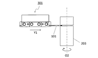
- the work material 203 is rotated around the shaft O2, and the cutting tool 101 attached to the machine tool 301 is relative to the work material 203. You may approach the target.
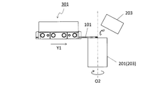
- the ridge line (cutting edge) of the cutting tool 101 may be brought into contact with the work material 203 to cut the work material 203.
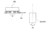
- the cutting tool 101 may be relatively far from the work material 203.
- the cutting tool 101 is moved in the Y1 direction while the shaft O2 is fixed and the work material 203 is rotated around the shaft O2 to bring the work material 203 closer to the work material 203. .. Further, in the non-limiting example shown in FIGS. 14 and 15, the work material 203 is cut by bringing the cutting edge (first upper blade 15) of the insert 1 into contact with the rotating work material 203. There is. Further, in an example not limited to that shown in FIG. 16, the cutting tool 101 is moved away in the Y2 direction while the work material 203 is rotated.
- the cutting tool 101 is brought into contact with the work material 203 or the cutting tool 101 is machined by moving the cutting tool 101 in each step. Although it is separated from the material 203, it is not limited to such a form as a matter of course.
- the work material 203 may be brought closer to the cutting tool 101.
- the work material 203 may be moved away from the cutting tool 101.
- the process of keeping the work material 203 rotated and bringing the cutting edge of the insert 1 into contact with different parts of the work material 203 may be repeated.
- typical examples of the material of the work material 203 may be carbon steel, alloy steel, stainless steel, cast iron, non-ferrous metal, or the like.
- Cutting tool 103 ... Holder 105 ... Pocket 107 ... Upper jaw 109 ... Lower jaw 201 ... ⁇ ⁇ Machined work 203 ⁇ ⁇ ⁇ Work material 301 ⁇ ⁇ ⁇ Machine tool O1 ⁇ ⁇ ⁇ Central axis O2 ⁇ ⁇ ⁇ Axis ⁇ 1 ⁇ ⁇ ⁇ First angle ⁇ 2 ⁇ ⁇ ⁇ Second angle ⁇ 3 ⁇ ⁇ ⁇ Third angle ⁇ 4 ... 4th angle W1 ... 1st width W2 ... 2nd width W3 ... 3rd width W4 ... 4th width
Landscapes
- Engineering & Computer Science (AREA)
- Mechanical Engineering (AREA)
- Cutting Tools, Boring Holders, And Turrets (AREA)
Abstract
本開示の限定されない一面に基づく切削インサートは、上面、下面、前側面及び後側面を有する。上面は、第1上刃及び上拘束面を有する。下面は、下拘束面を有する。下拘束面は、下凸部を有する。下凸部は、第1領域、第2領域及び第3領域を有する。第1領域は、上拘束面の反対側に位置する。第2領域は、第1領域よりも前側面の側に位置する。第3領域は、第1領域よりも後側面の側に位置する。第1領域のくさび角を第1角、第2領域のくさび角を第2角、第3領域のくさび角を第3角とする。第1角が、第2角及び第3角よりも小さい。
Description
本出願は、2019年3月13日に出願された日本国特許出願2019-046094号の優先権を主張するものであり、この先の出願の開示全体を、ここに参照のために取り込む。
本開示は、切削加工において用いられる切削インサートに関する。具体的には、溝入れ加工のような旋削加工に用いられる切削インサートに関する。
金属などの被削材を旋削加工する際に用いられる切削インサートとして、例えば、特表2011-520630号公報(特許文献1)に記載の切削チップが知られている。特許文献1に記載の切削チップ(切削インサート)は、上面、下面及び周辺側面を有する。周辺側面は、前方端面及び後方端面を有する。下面は、中心軸(縦軸)に沿って延びたV字溝の形状の拘束面を有する。拘束面は、前方端面の側に位置する第1の表面成分と、後方端面の側に位置する第2の表面成分と、を有する。そして、第2の表面成分におけるくさび角が、第1の表面成分におけるくさび角よりも小さい。
特許文献1に記載の切削インサートを用いて切削加工を行った場合には、第2の表面成分が後方端面の側に位置することから、第2の表面成分にも切削加工の主分力による切削負荷が伝わり易い。第2の表面成分におけるくさび角が相対的に小さいことから、第2の表面成分において切削インサートの耐久性が低下する恐れがある。
本開示の限定されない一面に基づく切削インサートは、上面、下面、前側面及び後側面を有する。下面は、上面の反対側に位置する。前側面は、上面及び下面の間に位置する。後側面は、上面及び下面の間であって、前側面の反対側に位置する。上面は、第1上刃及び上拘束面を有する。第1上刃は、前側面との交わりに位置する。上拘束面は、第1上刃よりも後側面の近くに位置し、ホルダに当接可能である。下面は、ホルダに当接可能な下拘束面を有する。下拘束面は、前側面の近くに位置する領域から後側面に向かって延びた下凸部を有する。
下凸部は、第1領域、第2領域及び第3領域を有する。第1領域は、上拘束面の反対側に位置する。第2領域は、第1領域よりも前側面の側に位置する。第3領域は、第1領域よりも後側面の側に位置する。下凸部の延びた方向に直交する断面において、第1領域のくさび角を第1角、第2領域のくさび角を第2角、第3領域のくさび角を第3角とする。第1角が、第2角及び第3角よりも小さい。
<切削インサート>
以下、本開示の限定されない実施形態の切削インサート1(以下、単にインサート1とも言う。)について、図面を用いて詳細に説明する。但し、以下で参照する各図は、説明の便宜上、実施形態を説明する上で必要な主要部材のみが簡略化して示されている。したがって、インサート1は、参照する各図に示されていない任意の構成部材を備え得る。また、各図中の部材の寸法は、実際の構成部材の寸法及び各部材の寸法比率等を忠実に表したものではない。
以下、本開示の限定されない実施形態の切削インサート1(以下、単にインサート1とも言う。)について、図面を用いて詳細に説明する。但し、以下で参照する各図は、説明の便宜上、実施形態を説明する上で必要な主要部材のみが簡略化して示されている。したがって、インサート1は、参照する各図に示されていない任意の構成部材を備え得る。また、各図中の部材の寸法は、実際の構成部材の寸法及び各部材の寸法比率等を忠実に表したものではない。
インサート1は、上面3、下面5、前側面7及び後側面9を有してもよい。下面5は、上面3の反対側に位置してもよい。前側面7及び後側面9は、それぞれ上面3及び下面5の間に位置してもよい。後側面9は、前側面7の反対側に位置してもよい。前側面7及び後側面9は、それぞれ上面3及び下面5に接続されてもよい。
なお、上面3及び下面5は、便宜上の表現であり、上及び下の方向性を示すものではない。例えば、上面3は、インサート1を使用するときに上方を向く面である必要はない。同様に、前側面7及び後側面9も、便宜上の表現であり、前及び後の方向性を示すものではない。これらの点は、上、下、前及び後の表現を含む他の部位においても同様である。
インサート1は、上述した面に加えて第1側面11及び第2側面13を有してもよい。第1側面11及び第2側面13は、それぞれ上面3及び下面5の間、且つ、前側面7及び後側面9の間に位置してもよい。第1側面11及び第2側面13は、それぞれ上面3、下面5、前側面7及び後側面9に接続されてもよい。
インサート1は、図1に示す限定されない一例のように、上面3、下面5、前側面7、後側面9、第1側面11及び第2側面13を有する四角柱形状であってもよい。図1に示す限定されない一例のように、インサート1は、中心軸O1に沿って先端から後端に向かって延びた角柱形状であってもよい。なお、中心軸O1は、前側面7の中心及び後側面9の中心を通る軸であってもよい。
前側面7は先端に位置してもよく、また、後側面9は後端に位置してもよい。図1に示す限定されない一例のように、前側面7及び後側面9がそれぞれ四角形であってもよく、前側面7から後側面9に向かって、上面3、下面5、第1側面11及び第2側面13の4つの面がそれぞれ延びてもよい。
上面3、下面5、前側面7、後側面9、第1側面11及び第2側面13は、それぞれ特定の大きさに限定されない。例えば、上面3を正面視した場合(上面視した場合)における中心軸O1に沿った方向での上面3の長さは、3~50mm程度に設定されてもよい。上面視した場合における中心軸O1に直交する方向での上面3の長さは、1.5~15mm程度に設定されてもよい。また、上面3及び下面5の間隔で示されるインサート1の高さは、2~20mm程度に設定されてもよい。
上面3は、第1上刃15及び上拘束面17を有してもよい。第1上刃15は、上面3における前側面7との交わりに位置してもよい。第1上刃15は、上面3及び前側面7の交わりの全体に位置してもよく、また、上面3及び前側面7の交わりの一部のみに位置してもよい。第1上刃15は、被削材の切削に用いられてもよい。図1に示す限定されない一例における第1上刃15は、一般的に、前切刃或いは主切刃とも呼ばれる。
上拘束面17は、第1上刃15よりも後側面9の近くに位置してもよい。上拘束面17は、インサート1をホルダに取り付けた際にホルダに当接(接触)可能である。上拘束面17は、上面3における後端の側の端部、すなわち後側面9との交わりを含んでもよく、また、この交わりから離れてもよい。
上面3は、第1上刃15に沿って位置するすくい面19を有してもよい。すくい面19は、上拘束面17に接続されてもよく、また、上拘束面17から離れてもよい。また、上面3は、切刃として第1上刃15に加えて第2上刃21をさらに有してもよい。
第2上刃21は、例えば、上面3における第1側面11との交わり、或いは、上面3における第2側面13との交わりに位置してもよい。例えば、図1に示す限定されない一例のように、上面3における第1側面11との交わり、及び、上面3における第2側面13との交わりのそれぞれに第2上刃21が位置してもよい。
下面5は、下拘束面23を有してもよい。下拘束面23は、下面5の全体に位置してもよく、また、下面5の一部のみに位置してもよい。下拘束面23は、インサート1をホルダに取り付けた際にホルダに当接(接触)可能である。下拘束面23及び上拘束面17をホルダに当接させることによって、インサート1をホルダで把持することが可能である。
下拘束面23は、前側面7の近くに位置する領域から後側面9に向かって延びた下凸部25を有してもよい。下凸部25は、前側面7に至ってもよく、また、前側面7から離れてもよい。同様に、下凸部25は、後側面9に至ってもよく、また、後側面9から離れてもよい。図3に示す限定されない一例のように、下凸部25は、前側面7及び後側面9から離れてもよい。
図3に示す限定されない一例において、下凸部25は、前側面7の側から後側面9の側に向かって延びることから、中心軸O1に対して平行に延びる、と言い換えてもよい。下凸部25は、その延びる方向に直交する断面、言い換えれば、中心軸O1に直交する断面において、凸形状であってもよい。
下凸部25は、下凸部25の頂部から離れるにしたがって間隔が広くなる一対の傾斜面27を有してもよい。そのため、例えば、下凸部25の頂部に、一対の傾斜面27を接続する凸曲面29が位置してもよい。
下凸部25は、第1領域31、第2領域33及び第3領域35を有してもよい。第1領域31は、上拘束面17の反対側に位置してもよい。第2領域33は、第1領域31よりも前側面7の側に位置してもよい。第2領域33は、下凸部25における前側面7の側の端部を含んでもよく、また、前側面7から離れてもよい。第3領域35は、第1領域31よりも後側面9の側に位置してもよい。第3領域35は、下凸部25における後側面9の側の端部を含んでもよく、また、後側面9から離れてもよい。
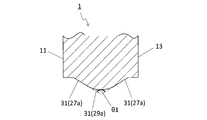
ここで、下凸部25の延びた方向に直交する断面、言い換えれば中心軸O1に直交する断面における、第1領域31、第2領域33及び第3領域35それぞれの形状を比較してもよい。具体的には、下凸部25の延びた方向に直交する断面において、第1領域31のくさび角を第1角θ1、第2領域33のくさび角を第2角θ2、第3領域35のくさび角を第3角θ3としてもよい。
なお、上記における「くさび角」とは、中心軸O1に直交する断面における一対の傾斜面27のなす角を意味してもよい。すなわち、中心軸O1に直交するとともに第1領域31を通る断面における下凸部25のくさび角が、第1角θ1であってもよい。中心軸O1に直交するとともに第2領域33を通る断面における下凸部25のくさび角が、第2角θ2であってもよい。中心軸O1に直交するとともに第3領域35を通る断面における下凸部25のくさび角が、第3角θ3であってもよい。
第1角θ1は、第2角θ2及び第3角θ3より小さくてもよい。この場合には、インサート1の耐久性が高い。第1角θ1が相対的に小さいことから、上面視した場合における中心軸O1に直交する方向でのインサート1の位置ずれが生じにくい。
さらに、第2角θ2及び第3角θ3が相対的に大きいことから、切削加工時にインサート1に加わる主分力を、前側面7の側に位置する第2領域33、及び、後側面9の側に位置する第3領域35で受け止め易い。主分力を第2領域33及び第3領域35で受け止め易いことから、これらの領域の間に位置する第1領域31に、上記の主分力が加わりにくい。そのため、インサート1の耐久性が高い。
第1角θ1、第2角θ2及び第3角θ3は、特定の値に限定されない。第1角θ1は、例えば100°~140°に設定されてもよい。第2角θ2は、例えば120°~160°に設定されてもよい。第3角θ3は、例えば120°~160°に設定されてもよい。
第1角θ1、第2角θ2及び第3角θ3は、それぞれ一定であってもよく、また、変化してもよい。例えば、第1角θ1が変化するとともに、第2角θ2及び第3角θ3が一定であってもよい。具体的には、第1領域31が、前側面7の側に位置して、後側面9に近づくにしたがってくさび角(第1角θ1)が小さくなる第1部分37と、後側面9の側に位置して、前側面7に近づくにしたがってくさび角(第1角θ1)が小さくなる第2部分39と、を有してもよい。第1部分37は、下凸部25の延びた方向における第1領域31の中央よりも前側面7の側に位置してもよい。第2部分39は、下凸部25の延びた方向における第1領域31の中央よりも後側面9の側に位置してもよい。なお、第1部分37及び第2部分39の間に位置し、且つ、第1領域31の中央を含む部分は、くさび角(第1角θ1)が一定であってもよい。
第1領域31が上記の第1部分37を有する場合には、第1領域31及び第2領域33の境界において、くさび角が急激に変化することが避けられ易い。また、第1領域31が上記の第2部分39を有する場合には、第1領域31及び第3領域35の境界において、くさび角が急激に変化することが避けられ易い。そのため、インサート1の耐久性がさらに高い。
また、第2角θ2が一定である場合には、第2領域33における一対の傾斜面27が平面形状である。そのため、第2領域33がホルダに面接触し易い。同様に、第3角θ3が一定である場合には、第3領域35における一対の傾斜面27が平面形状である。そのため、第3領域35がホルダに面接触し易い。この場合には、上記した主分力を、第2領域33及び第3領域35でさらに受け止め易い。
なお、第1角θ1、第2角θ2及び第3角θ3が変化する場合には、それぞれの最大値を比較してもよい。
第2角θ2は、第3角θ3と同じであってもよく、また、第3角θ3と異なってもよい。図8及び図9に示す限定されない一例のように、第2角θ2は、第3角θ3よりも小さくてもよい。第2領域33は、第1領域31及び第3領域35と比較して前側面7の近くに位置してもよい。すなわち、第2領域33は、第1領域31及び第3領域35と比較して第1上刃15の近くに位置してもよい。
切削加工時に切削負荷が加わる第1上刃15の近くに位置してもよい第2領域33における第2角θ2が第3角θ3よりも小さい場合には、上面視した場合における中心軸O1に直交する方向でのインサート1の位置ずれが生じにくい。
上拘束面17は、前側面7の近くに位置する領域から後側面9に向かって延びた上凸部41を有してもよい。上凸部41は、前側面7に至ってもよく、また、前側面7から離れてもよい。同様に、上凸部41は、後側面9に至ってもよく、また、後側面9から離れてもよい。
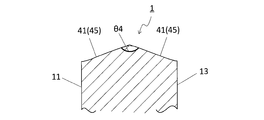
図2に示す限定されない一例において、上凸部41は、前側面7の側から後側面9の側に向かって延びることから、中心軸O1に対して平行に延びる、と言い換えてもよい。上凸部41は、その延びる方向に直交する断面、言い換えれば、中心軸O1に直交する断面において、凸形状であってもよい。すなわち、上凸部41は、上凸部41の頂部から離れるにしたがって間隔が広くなる一対の傾斜面45を有してもよい。
上拘束面17が上凸部41を有する場合には、インサート1をホルダで安定して把持することが可能である。特に、上凸部41が下凸部25に対して平行に延びる場合には、インサート1をホルダでさらに安定して把持することが可能である。
図10に示す限定されない一例のように、上凸部41のくさび角を第4角θ4としてもよい。第1角θ1は、第4角θ4と同じであってもよく、また、第4角θ4と異なってもよい。第1角θ1が第4角θ4よりも小さい、言い換えれば、第4角θ4が第1角θ1よりも大きい場合には、インサート1の耐久性がさらに高い。第1角θ1を相対的に小さな値にしつつ、上凸部41の頂部から下凸部25の頂部にかけてクラックが生じるおそれを小さくできる。
上凸部41及び下凸部25の互いに反対側に位置する部分の少なくとも一部において、くさび角が同じである場合には、インサート1をホルダで安定して把持できる。例えば、第3領域35が、上拘束面17の反対側に位置する第1部位43を有してもよく、第1部位43における第3角θ3が、第4角θ4と同じであってもよい。
なお、ここで角度が同じであるとは厳密に同じであることを求めない。2つの角度が2°程度の僅かな違いである場合には、これらの角度が同じであると見做してもよい。
上記したように、下凸部25の頂部に、一対の傾斜面27を接続する凸曲面29が位置してもよい。例えば、第1領域31における凸曲面形状の頂部を第1頂部29a、第1領域31における一対の傾斜面27を第1傾斜面27aとしてもよい。すなわち、第1領域31が、凸曲面形状の第1頂部29aと、下凸部25の延びた方向に沿って第1頂部29aに接続された平らな第1傾斜面27aを有してもよい。
ここで、下凸部25の延びた方向における第1頂部29aの幅を第1幅W1、下凸部25の延びた方向における第1傾斜面27aの幅を第2幅W2としてもよい。第1幅W1の最大値が、第2幅W2の最大値より大きくてもよい。この場合には、上面視した場合における中心軸O1に直交する方向でのインサート1の位置ずれがさらに生じにくい。
例えば、第2領域33における凸曲面形状の頂部を第2頂部29b、第2領域33における一対の傾斜面27を第2傾斜面27bとしてもよい。すなわち、第2領域33が、凸曲面形状の第2頂部29bと、下凸部25の延びた方向に沿って第2頂部29bに接続された平らな第2傾斜面27bを有してもよい。
ここで、下凸部25の延びた方向における第2頂部29bの幅を第3幅W3、下凸部25の延びた方向における第2傾斜面27bの幅を第4幅W4としてもよい。第3幅W3の最大値が、第4幅W4の最大値より小さくてもよい。この場合には、第2領域33の耐久性が高い。
例えば、第3領域35における凸曲面形状の頂部を第3頂部29c、第3領域35における一対の傾斜面27を第3傾斜面27cとしてもよい。すなわち、第3領域35が、凸曲面形状の第3頂部29cと、下凸部25の延びた方向に沿って第3頂部29cに接続された平らな第3傾斜面27cを有してもよい。
図6に示す限定されない一例のように、第1頂部29aが、第2頂部29b及び第3頂部29cより上面3の近くに位置してもよい。すなわち、側面視した場合に、凸曲面29は、第1領域31に位置する部分が窪んだ形状であってもよい。この場合には、くさび角が相対的に大きい第2領域33及び第3領域35を安定してホルダに当接させることができる。
また、図3に示す限定されない一例のように、下面5を正面視した場合において、中心軸O1に直交する方向における第1領域31の幅が、中心軸O1に直交する方向における第2領域33の幅及び第3領域35の幅より狭くてもよい。この場合には、第1角θ1が、第2角θ2及び第3角θ3より小さく、且つ、第1頂部29aが、第2頂部29b及び第3頂部29cより上面3の近くに位置する構成にし易い。
インサート1の材質としては、例えば、超硬合金、サーメット及びセラミックスなどの無機材料が挙げられ得る。超硬合金の組成としては、例えば、WC(炭化タングステン)-Co、WC-TiC(炭化チタン)-Co及びWC-TiC-TaC(炭化タンタル)-Coが挙げられ得る。ここで、WC、TiC及びTaCは硬質粒子であってもよく、Coは結合相であってもよい。
また、サーメットは、セラミック成分に金属を複合させた焼結複合材料であってもよい。具体的には、サーメットとして、TiC又はTiN(窒化チタン)を主成分とした化合物が挙げられ得る。インサート1の材質がこれらに限定されないことは言うまでもない。
また、特に図示はしないが、インサート1は、上記の材質を含有する本体(基体)及びこの本体を被覆する被覆層を備えた構成であってもよい。被覆層の材質としては、例えば、チタンの炭化物、窒化物、酸化物、炭酸化物、窒酸化物、炭窒化物及び炭窒酸化物などが挙げられ得る。
被覆層は、上記の材質のうち1つのみを含有してもよく、複数を含有してもよい。また、被覆層は、1つのみの層によって構成されてもよく、複数の層が積層された構成であってもよい。なお、被覆層の材質は、これらに限定されない。
被覆層は、化学蒸着(CVD)法又は物理蒸着(PVD)法を用いることによって、本体の上に位置させてもよい。
<切削工具>
次に、本開示の限定されない実施形態の切削工具101について図面を用いて説明する。
次に、本開示の限定されない実施形態の切削工具101について図面を用いて説明する。
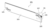
本開示の限定されない実施形態の切削工具101は、ホルダ103及びインサート1を有してもよい。ホルダ103は、棒形状であってもよく、また、図11に示す限定されない一例のように、第1端(図11における右下端)から第2端(図11における左上端)にかけて延びた板形状であってもよい。
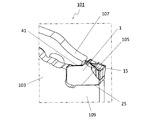
また、ホルダ103は第1端の側に位置するポケット105を有してもよい。図12に示す限定されない一例のように、ホルダ103が第1端の側に位置するとともに互いに離れて位置する上顎107及び下顎109を有してもよく、この上顎107及び下顎109によってポケット105が構成されてもよい。
インサート1は、ポケット105に位置してもよい。言い換えれば、インサート1は、上顎107及び下顎109によって挟まれてもよい。インサート1は、切刃として用いられる部分の少なくとも一部がホルダ103から外方に突出するように装着されてもよい。
ホルダ103の部材として、鋼及び鋳鉄などが用いられてもよい。特に、これらの部材の中で鋼が用いられた場合には、ホルダ103の靱性が高い。
図11に示す限定されない一例においては、いわゆる旋削加工に用いられる切削工具101が示されている。本開示の限定されない実施形態の切削工具101は、溝入れ加工において用いられることが可能であるが、このような加工に限定されない。例えば、限定されない実施形態の切削工具101が、内径加工、外径加工及び横送り加工に用いられても何ら問題ない。
<切削加工物の製造方法>
次に、本開示の限定されない実施形態の切削加工物201の製造方法について図面を用いて説明する。
次に、本開示の限定されない実施形態の切削加工物201の製造方法について図面を用いて説明する。
切削加工物201は、被削材203を切削加工することによって作製され得る。本開示の限定されない実施形態における切削加工物201の製造方法は、以下の工程を備えてもよい。すなわち、
(1)被削材203を回転させる工程と、
(2)回転している被削材203に上記の限定されない実施形態に代表される切削工具101を接触させる工程と、
(3)切削工具101を被削材203から離す工程と、
を備えてもよい。
(1)被削材203を回転させる工程と、
(2)回転している被削材203に上記の限定されない実施形態に代表される切削工具101を接触させる工程と、
(3)切削工具101を被削材203から離す工程と、
を備えてもよい。
より具体的には、まず、図13に示す限定されない一例のように、被削材203を軸O2の周りで回転させるとともに、被削材203に工作機械301に取り付けられた切削工具101を相対的に近付けてもよい。次に、図14及び図15に示す限定されない一例のように、切削工具101における稜線(切刃)を被削材203に接触させて、被削材203を切削してもよい。そして、図16に示す限定されない一例のように、切削工具101を被削材203から相対的に遠ざけてもよい。
図13に示す限定されない一例においては、軸O2を固定するとともに被削材203を軸O2の周りで回転させた状態で切削工具101をY1方向に移動させることによって被削材203に近づけている。また、図14及び図15に示す限定されない一例おいては、回転している被削材203にインサート1における切刃(第1上刃15)を接触させることによって被削材203を切削している。また、図16に示す限定されない一例おいては、被削材203を回転させた状態で切削工具101をY2方向に移動させることによって遠ざけている。
なお、本開示の限定されない実施形態の製造方法における切削加工では、それぞれの工程において、切削工具101を動かすことによって、切削工具101を被削材203に接触させる、あるいは、切削工具101を被削材203から離しているが、当然ながらこのような形態に限定されない。
例えば、(1)の工程において、被削材203を切削工具101に近づけてもよい。同様に、(3)の工程において、被削材203を切削工具101から遠ざけてもよい。切削加工を継続する場合には、被削材203を回転させた状態を維持して、被削材203の異なる箇所にインサート1における切刃を接触させる工程を繰り返せばよい。
なお、被削材203の材質の代表例としては、炭素鋼、合金鋼、ステンレス、鋳鉄、又は非鉄金属などが挙げられ得る。
1・・・切削インサート(インサート)
3・・・上面
5・・・下面
7・・・前側面
9・・・後側面
11・・・第1側面
13・・・第2側面
15・・・第1上刃
17・・・上拘束面
19・・・すくい面
21・・・第2上刃
23・・・下拘束面
25・・・下凸部
27・・・傾斜面
27a・・第1傾斜面
27b・・第2傾斜面
29・・・凸曲面
29a・・第1頂部
29b・・第2頂部
31・・・第1領域
33・・・第2領域
35・・・第3領域
37・・・第1部分
39・・・第2部分
41・・・上凸部
43・・・第1部位
45・・・傾斜面
101・・・切削工具
103・・・ホルダ
105・・・ポケット
107・・・上顎
109・・・下顎
201・・・切削加工物
203・・・被削材
301・・・工作機械
O1・・・中心軸
O2・・・軸
θ1・・・第1角
θ2・・・第2角
θ3・・・第3角
θ4・・・第4角
W1・・・第1幅
W2・・・第2幅
W3・・・第3幅
W4・・・第4幅
3・・・上面
5・・・下面
7・・・前側面
9・・・後側面
11・・・第1側面
13・・・第2側面
15・・・第1上刃
17・・・上拘束面
19・・・すくい面
21・・・第2上刃
23・・・下拘束面
25・・・下凸部
27・・・傾斜面
27a・・第1傾斜面
27b・・第2傾斜面
29・・・凸曲面
29a・・第1頂部
29b・・第2頂部
31・・・第1領域
33・・・第2領域
35・・・第3領域
37・・・第1部分
39・・・第2部分
41・・・上凸部
43・・・第1部位
45・・・傾斜面
101・・・切削工具
103・・・ホルダ
105・・・ポケット
107・・・上顎
109・・・下顎
201・・・切削加工物
203・・・被削材
301・・・工作機械
O1・・・中心軸
O2・・・軸
θ1・・・第1角
θ2・・・第2角
θ3・・・第3角
θ4・・・第4角
W1・・・第1幅
W2・・・第2幅
W3・・・第3幅
W4・・・第4幅
Claims (9)
- 上面と、
前記上面の反対側に位置する下面と、
前記上面及び前記下面の間に位置する前側面と、
前記上面及び前記下面の間であって、前記前側面の反対側に位置する後側面と、を有し、
前記上面は、
前記前側面との交わりに位置する第1上刃と、
前記第1上刃よりも前記後側面の近くに位置し、ホルダに当接可能な上拘束面と、を有し、
前記下面は、ホルダに当接可能な下拘束面を有し、
前記下拘束面は、前記前側面の近くに位置する領域から前記後側面に向かって延びた下凸部を有し、
前記下凸部は、
前記上拘束面の反対側に位置する第1領域と、
前記第1領域よりも前記前側面の側に位置する第2領域と、
前記第1領域よりも前記後側面の側に位置する第3領域と、を有し、
前記下凸部の延びた方向に直交する断面において、前記第1領域のくさび角を第1角、前記第2領域のくさび角を第2角、前記第3領域のくさび角を第3角としたとき、
前記第1角が、前記第2角及び前記第3角よりも小さい、切削インサート。 - 前記第2角が、前記第3角よりも小さい、請求項1に記載の切削インサート。
- 前記上拘束面は、前記前側面の近くに位置する領域から前記後側面に向かって延びた上凸部を有し、
前記上凸部は、前記下凸部に対して平行に延びている、請求項1又は2に記載の切削インサート。 - 前記上凸部の延びた方向に直交する断面において、前記上凸部のくさび角を第4角としたとき、
前記第1角が、前記第4角よりも小さい、請求項3に記載の切削インサート。 - 前記第3領域は、前記上拘束面の反対側に位置する第1部位を有し、
前記第1部位における前記第3角が、前記第4角と同じである、請求項4に記載の切削インサート。 - 前記第1領域は、
凸曲面形状の第1頂部と、
前記下凸部の延びた方向に沿って前記第1頂部に接続された平らな第1傾斜面を有し、
前記下凸部の延びた方向における前記第1頂部の幅を第1幅、前記下凸部の延びた方向における前記第1傾斜面の幅を第2幅としたとき、
前記第1幅の最大値が、前記第2幅の最大値よりも大きい、請求項1~5のいずれか1つに記載の切削インサート。 - 前記第2領域は、
凸曲面形状の第2頂部と、
前記下凸部の延びた方向に沿って前記第2頂部に接続された平らな第2傾斜面を有し、
前記下凸部の延びた方向における前記第2頂部の幅を第3幅、前記下凸部の延びた方向における前記第2傾斜面の幅を第4幅としたとき、
前記第3幅の最大値が、前記第4幅の最大値よりも小さい、請求項1~6のいずれか1つに記載の切削インサート。 - 第1端から第2端にかけて延びた板形状であって、前記第1端の側に位置するポケットを有するホルダと、
前記ポケット内に位置する、請求項1~7のいずれか1つに記載の切削インサートと、を有する切削工具。 - 被削材を回転させる工程と、
回転している前記被削材に請求項8に記載の切削工具を接触させる工程と、
前記切削工具を前記被削材から離す工程と、を備えた切削加工物の製造方法。
Priority Applications (4)
| Application Number | Priority Date | Filing Date | Title |
|---|---|---|---|
| CN202080018432.9A CN113518679B (zh) | 2019-03-13 | 2020-03-06 | 切削刀片、切削刀具以及切削加工物的制造方法 |
| JP2021505017A JP7204882B2 (ja) | 2019-03-13 | 2020-03-06 | 切削インサート、切削工具及び切削加工物の製造方法 |
| DE112020001176.3T DE112020001176T5 (de) | 2019-03-13 | 2020-03-06 | Schneideinsatz, schneidwerkzeug und verfahren zur herstellung eines maschinell bearbeiteten produkts |
| US17/437,840 US12109631B2 (en) | 2019-03-13 | 2020-03-06 | Cutting insert, cutting tool, and method for manufacturing machined product |
Applications Claiming Priority (2)
| Application Number | Priority Date | Filing Date | Title |
|---|---|---|---|
| JP2019-046094 | 2019-03-13 | ||
| JP2019046094 | 2019-03-13 |
Publications (1)
| Publication Number | Publication Date |
|---|---|
| WO2020184422A1 true WO2020184422A1 (ja) | 2020-09-17 |
Family
ID=72427502
Family Applications (1)
| Application Number | Title | Priority Date | Filing Date |
|---|---|---|---|
| PCT/JP2020/009629 Ceased WO2020184422A1 (ja) | 2019-03-13 | 2020-03-06 | 切削インサート、切削工具及び切削加工物の製造方法 |
Country Status (5)
| Country | Link |
|---|---|
| US (1) | US12109631B2 (ja) |
| JP (1) | JP7204882B2 (ja) |
| CN (1) | CN113518679B (ja) |
| DE (1) | DE112020001176T5 (ja) |
| WO (1) | WO2020184422A1 (ja) |
Citations (3)
| Publication number | Priority date | Publication date | Assignee | Title |
|---|---|---|---|---|
| US5360298A (en) * | 1992-04-28 | 1994-11-01 | Sandvik Ab | Tool for cut-off or similar turning operations |
| JP2006167874A (ja) * | 2004-12-16 | 2006-06-29 | Mitsubishi Materials Corp | 切削インサートのクランプ機構 |
| JP2011520630A (ja) * | 2008-05-18 | 2011-07-21 | イスカーリミテッド | 切削工具およびそのための切削チップ |
Family Cites Families (10)
| Publication number | Priority date | Publication date | Assignee | Title |
|---|---|---|---|---|
| JPH0871811A (ja) * | 1994-09-12 | 1996-03-19 | Mitsubishi Materials Corp | スローアウェイチップ、バイトホルダ及び溝入れ用バイト |
| US7883300B1 (en) | 2002-10-18 | 2011-02-08 | Kennametal Inc. | Tool holder and metal cutting insert with chip breaking surfaces |
| CN101274371A (zh) * | 2007-03-30 | 2008-10-01 | 三菱麻铁里亚尔株式会社 | 切削刀片 |
| JP2011125948A (ja) * | 2009-12-17 | 2011-06-30 | Kyocera Corp | ホルダおよび切削工具、並びにそれを用いた被削材の切削方法 |
| IL205091A (en) * | 2010-04-14 | 2014-01-30 | Iscar Ltd | Cutting tools and cutting tool for him |
| US9517509B2 (en) * | 2010-12-25 | 2016-12-13 | Kyocera Corporation | Cutting tool and method of manufacturing machined product using the same |
| US10010939B2 (en) * | 2014-05-22 | 2018-07-03 | Kyocera Corporation | Cutting insert, cutting tool, and method for manufacturing machined product |
| JP6186335B2 (ja) * | 2014-10-28 | 2017-08-23 | 日本特殊陶業株式会社 | 切削インサート |
| CN206952190U (zh) * | 2017-06-29 | 2018-02-02 | 株洲钻石切削刀具股份有限公司 | 一种用于槽加工的切削刀具 |
| JP6985856B2 (ja) | 2017-08-31 | 2021-12-22 | キヤノン株式会社 | 情報処理装置、情報処理装置の制御方法及びプログラム |
-
2020
- 2020-03-06 WO PCT/JP2020/009629 patent/WO2020184422A1/ja not_active Ceased
- 2020-03-06 JP JP2021505017A patent/JP7204882B2/ja active Active
- 2020-03-06 DE DE112020001176.3T patent/DE112020001176T5/de active Pending
- 2020-03-06 US US17/437,840 patent/US12109631B2/en active Active
- 2020-03-06 CN CN202080018432.9A patent/CN113518679B/zh active Active
Patent Citations (3)
| Publication number | Priority date | Publication date | Assignee | Title |
|---|---|---|---|---|
| US5360298A (en) * | 1992-04-28 | 1994-11-01 | Sandvik Ab | Tool for cut-off or similar turning operations |
| JP2006167874A (ja) * | 2004-12-16 | 2006-06-29 | Mitsubishi Materials Corp | 切削インサートのクランプ機構 |
| JP2011520630A (ja) * | 2008-05-18 | 2011-07-21 | イスカーリミテッド | 切削工具およびそのための切削チップ |
Also Published As
| Publication number | Publication date |
|---|---|
| JPWO2020184422A1 (ja) | 2020-09-17 |
| JP7204882B2 (ja) | 2023-01-16 |
| CN113518679B (zh) | 2023-12-22 |
| DE112020001176T5 (de) | 2021-12-02 |
| CN113518679A (zh) | 2021-10-19 |
| US20220143714A1 (en) | 2022-05-12 |
| US12109631B2 (en) | 2024-10-08 |
Similar Documents
| Publication | Publication Date | Title |
|---|---|---|
| WO2016047795A1 (ja) | 切削インサート、切削工具及び切削加工物の製造方法 | |
| JP7093784B2 (ja) | 切削インサート、切削工具及び切削加工物の製造方法 | |
| US20210114118A1 (en) | Insert and cutting tool assembly comprising same | |
| WO2021235261A1 (ja) | 切削インサート、切削工具、および切削加工物の製造方法 | |
| WO2020203414A1 (ja) | 切削インサート、旋削工具及び切削加工物の製造方法 | |
| JP6847230B2 (ja) | 切削インサート、切削工具及び切削加工物の製造方法 | |
| JP6882473B2 (ja) | 切削インサート、切削工具及び切削加工物の製造方法 | |
| JP7114733B2 (ja) | 切削インサート、切削工具及び切削加工物の製造方法 | |
| WO2021095520A1 (ja) | 切削インサート、切削工具及び切削加工物の製造方法 | |
| JP7155397B2 (ja) | 切削インサート、切削工具及び切削加工物の製造方法 | |
| JP6892505B2 (ja) | 切削インサート、これを備えた切削工具及び切削加工物の製造方法 | |
| JP7204882B2 (ja) | 切削インサート、切削工具及び切削加工物の製造方法 | |
| JP7177908B2 (ja) | 切削インサート、切削工具及び切削加工物の製造方法 | |
| KR102540681B1 (ko) | 절삭 인서트, 절삭 공구 및 절삭 가공물의 제조 방법 | |
| WO2019022016A1 (ja) | 切削インサート、切削工具及び切削加工物の製造方法 | |
| JP7344376B2 (ja) | 切削インサート、切削工具および切削加工物の製造方法 | |
| JP7239480B2 (ja) | 切削インサート、切削工具及び切削加工物の製造方法 | |
| WO2024209781A1 (ja) | 切削インサート、切削工具及び切削加工物の製造方法 | |
| JP2019130647A (ja) | 切削インサート、切削工具及び切削加工物の製造方法 | |
| WO2021235258A1 (ja) | 切削インサート、切削工具および切削加工物の製造方法 | |
| JPWO2020066958A1 (ja) | 切削インサート、切削工具及び切削加工物の製造方法 |
Legal Events
| Date | Code | Title | Description |
|---|---|---|---|
| 121 | Ep: the epo has been informed by wipo that ep was designated in this application |
Ref document number: 20770521 Country of ref document: EP Kind code of ref document: A1 |
|
| ENP | Entry into the national phase |
Ref document number: 2021505017 Country of ref document: JP Kind code of ref document: A |
|
| 122 | Ep: pct application non-entry in european phase |
Ref document number: 20770521 Country of ref document: EP Kind code of ref document: A1 |