WO2020184065A1 - 建設機械 - Google Patents
建設機械 Download PDFInfo
- Publication number
- WO2020184065A1 WO2020184065A1 PCT/JP2020/005800 JP2020005800W WO2020184065A1 WO 2020184065 A1 WO2020184065 A1 WO 2020184065A1 JP 2020005800 W JP2020005800 W JP 2020005800W WO 2020184065 A1 WO2020184065 A1 WO 2020184065A1
- Authority
- WO
- WIPO (PCT)
- Prior art keywords
- range
- blind spot
- construction machine
- environment recognition
- machine
- Prior art date
Links
Images


Classifications
-
- E—FIXED CONSTRUCTIONS
- E02—HYDRAULIC ENGINEERING; FOUNDATIONS; SOIL SHIFTING
- E02F—DREDGING; SOIL-SHIFTING
- E02F9/00—Component parts of dredgers or soil-shifting machines, not restricted to one of the kinds covered by groups E02F3/00 - E02F7/00
- E02F9/20—Drives; Control devices
-
- E—FIXED CONSTRUCTIONS
- E02—HYDRAULIC ENGINEERING; FOUNDATIONS; SOIL SHIFTING
- E02F—DREDGING; SOIL-SHIFTING
- E02F9/00—Component parts of dredgers or soil-shifting machines, not restricted to one of the kinds covered by groups E02F3/00 - E02F7/00
- E02F9/26—Indicating devices
- E02F9/261—Surveying the work-site to be treated
- E02F9/262—Surveying the work-site to be treated with follow-up actions to control the work tool, e.g. controller
-
- B—PERFORMING OPERATIONS; TRANSPORTING
- B60—VEHICLES IN GENERAL
- B60Q—ARRANGEMENT OF SIGNALLING OR LIGHTING DEVICES, THE MOUNTING OR SUPPORTING THEREOF OR CIRCUITS THEREFOR, FOR VEHICLES IN GENERAL
- B60Q9/00—Arrangement or adaptation of signal devices not provided for in one of main groups B60Q1/00 - B60Q7/00, e.g. haptic signalling
- B60Q9/008—Arrangement or adaptation of signal devices not provided for in one of main groups B60Q1/00 - B60Q7/00, e.g. haptic signalling for anti-collision purposes
-
- E—FIXED CONSTRUCTIONS
- E02—HYDRAULIC ENGINEERING; FOUNDATIONS; SOIL SHIFTING
- E02F—DREDGING; SOIL-SHIFTING
- E02F3/00—Dredgers; Soil-shifting machines
- E02F3/04—Dredgers; Soil-shifting machines mechanically-driven
- E02F3/28—Dredgers; Soil-shifting machines mechanically-driven with digging tools mounted on a dipper- or bucket-arm, i.e. there is either one arm or a pair of arms, e.g. dippers, buckets
- E02F3/30—Dredgers; Soil-shifting machines mechanically-driven with digging tools mounted on a dipper- or bucket-arm, i.e. there is either one arm or a pair of arms, e.g. dippers, buckets with a dipper-arm pivoted on a cantilever beam, i.e. boom
- E02F3/32—Dredgers; Soil-shifting machines mechanically-driven with digging tools mounted on a dipper- or bucket-arm, i.e. there is either one arm or a pair of arms, e.g. dippers, buckets with a dipper-arm pivoted on a cantilever beam, i.e. boom working downwardly and towards the machine, e.g. with backhoes
-
- E—FIXED CONSTRUCTIONS
- E02—HYDRAULIC ENGINEERING; FOUNDATIONS; SOIL SHIFTING
- E02F—DREDGING; SOIL-SHIFTING
- E02F9/00—Component parts of dredgers or soil-shifting machines, not restricted to one of the kinds covered by groups E02F3/00 - E02F7/00
- E02F9/20—Drives; Control devices
- E02F9/2025—Particular purposes of control systems not otherwise provided for
- E02F9/2033—Limiting the movement of frames or implements, e.g. to avoid collision between implements and the cabin
-
- E—FIXED CONSTRUCTIONS
- E02—HYDRAULIC ENGINEERING; FOUNDATIONS; SOIL SHIFTING
- E02F—DREDGING; SOIL-SHIFTING
- E02F9/00—Component parts of dredgers or soil-shifting machines, not restricted to one of the kinds covered by groups E02F3/00 - E02F7/00
- E02F9/24—Safety devices, e.g. for preventing overload
-
- E—FIXED CONSTRUCTIONS
- E02—HYDRAULIC ENGINEERING; FOUNDATIONS; SOIL SHIFTING
- E02F—DREDGING; SOIL-SHIFTING
- E02F9/00—Component parts of dredgers or soil-shifting machines, not restricted to one of the kinds covered by groups E02F3/00 - E02F7/00
- E02F9/26—Indicating devices
-
- H—ELECTRICITY
- H04—ELECTRIC COMMUNICATION TECHNIQUE
- H04W—WIRELESS COMMUNICATION NETWORKS
- H04W4/00—Services specially adapted for wireless communication networks; Facilities therefor
- H04W4/02—Services making use of location information
- H04W4/023—Services making use of location information using mutual or relative location information between multiple location based services [LBS] targets or of distance thresholds
Definitions
- the present invention relates to construction machinery.
- Patent Document 1 In construction machines such as hydraulic excavators in the construction and civil engineering construction industry, as a means of preventing contact between a front work machine performing work and a worker, for example, the working speed of the front work machine is set as described in Patent Document 1. There is a technology to control.
- Patent Document 1 describes an attachment rotatably attached to a traveling body (base), a swivel mechanism for swiveling the attachment, a control device for controlling the swivel mechanism, and a position of an approaching object that has entered the work area.
- the control device has a first physical quantity related to at least one of the current angular velocity of the attachment and the current moment of inertia of the attachment, and the approaching object detected by the approaching object detecting device.
- a swivel work machine that controls the swivel motion of an attachment based on its position is disclosed.
- the present invention has been made in view of the above, and a construction machine capable of dealing with a moving body in a blind spot of an object and more reliably preventing contact between a front working machine and a moving body.
- the purpose is to provide.
- the present application includes a plurality of means for solving the above problems, and to give an example thereof, a main body including a lower traveling body, an upper rotating body provided so as to be rotatable with respect to the lower traveling body, and the above.
- a posture detecting device provided on the front member of the front working machine to detect the posture information of the front member, an external environment recognition device for detecting an object around the main body, and the external environment recognition device recognize the machine.
- the blind spot range which is the range of the blind spot
- the assumed movement range which is the range in which the moving body assumed to exist in the blind spot can move in a predetermined time
- the movable range which is the range in which the front work machine can move in a predetermined time
- a control device for performing preventive control for preventing contact between the moving body and the front working machine is provided based on the movable range of the machine.
- the present invention it is possible to sufficiently cope with a moving body in a blind spot of an object, and it is possible to more reliably prevent contact between the front working machine and the moving body.
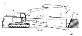
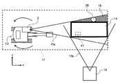
- FIG. 1 is a diagram schematically showing the appearance of a hydraulic excavator which is an example of a construction machine according to the present embodiment. Further, FIG. 2 is a side view schematically showing the appearance of the hydraulic excavator.
- the hydraulic excavator 100 is configured by connecting a plurality of driven members (boom 8, arm 9, bucket (working tool) 10) that rotate in the vertical direction, respectively. It includes an articulated front working machine 24, an upper swivel body 22 and a lower traveling body 20 constituting an excavator main body (hereinafter, simply referred to as “main body”), and the upper swivel body 22 travels downward via a swivel mechanism 21. It is provided so as to be rotatable with respect to the body 20.
- the swivel mechanism 21 has a swivel motor 23 and a swivel angle detection device 27.
- the swivel motor 23 swivels the upper swivel body 22 with respect to the lower traveling body 20, and the swivel angle detecting device 27 swivels the lower traveling body. The turning angle with respect to 20 is detected.
- the base end of the boom 8 of the front working machine 24 is vertically rotatably supported by the front portion of the upper swing body 22, and one end of the arm 9 is at an end (tip) different from the base end of the boom 8. It is rotatably supported in the vertical direction, and the bucket 10 is rotatably supported in the vertical direction at the other end of the arm 9.
- the boom 8, arm 9, bucket 10, upper swing body 22, and lower traveling body 20 are hydraulic actuators such as a boom cylinder 5, an arm cylinder 6, a bucket cylinder 7, a swing motor 23, and left and right traveling motors 3 (however, the left and right traveling motors 3). Only one traveling motor is shown).
- the z-axis whose origin is the intersection of the turning center axis 25 of the upper turning body 22 and the lower surface of the upper turning body 22 and whose upper side is positive along the turning center axis 25 is perpendicular to the z-axis from the origin.
- a main body coordinate system is set having an x-axis having a positive front in the front-rear direction and a positive y-axis in the left-right direction perpendicular to the z-axis and the x-axis from the origin.
- the cab 2 on which the operator is boarding is mounted on the front left side of the upper swivel body 22. Further, a control device 44 for controlling the overall operation of the hydraulic excavator 100 is arranged on the upper swing body 22.
- the cab 2 is provided with operation levers (operation devices) 2a and 2b that output operation signals for operating the hydraulic actuators 5 to 7, 23.
- the operating levers 2a and 2b can be tilted back and forth and left and right, respectively, and include a detection device (not shown) that electrically detects the tilting amount of the lever, which is an operation signal, that is, the lever operating amount.
- the lever operation amount is output to the control device 44 (described later) via electrical wiring. That is, the operations of the hydraulic actuators 5 to 7 and 23 are assigned to the operation levers 2a and 2b in the front-rear direction or the left-right direction, respectively.
- the operation control of the boom cylinder 5, arm cylinder 6, bucket cylinder 7, swivel motor 23, and left and right traveling motors 3 is performed by hydraulic actuators 3, 5 to each from a hydraulic pump device driven by a prime mover such as an engine or an electric motor (not shown). This is done by controlling the direction and flow rate of the hydraulic oil supplied to 7 and 23 with a control valve or the like.
- the operation of the control valve is controlled by the control device 44 based on the operation signals from the operation levers 2a and 2b, whereby the operations of the hydraulic actuators 5 to 7 and 23 are controlled.
- Posture sensors 34A, 34B, and 34C are attached to the base of the boom 8, the connection between the boom 8 and the arm 9, and the connection between the arm 9 and the bucket 10, respectively.
- the attitude sensors 34A, 34B, 34C are mechanical angle sensors such as potentiometers, for example.
- the posture sensor 34A measures the angle ⁇ 1 formed by the longitudinal direction of the boom 8 (a straight line connecting the rotation centers at both ends) and the xy plane and transmits the angle ⁇ 1 to the control device 44.
- the attitude sensor 34B measures the angle ⁇ 2 formed by the longitudinal direction of the boom 8 (straight line connecting the rotation centers at both ends) and the longitudinal direction of the arm 9 (straight line connecting the rotation centers at both ends), and the control device 44.
- the attitude sensor 34C measures the angle ⁇ 3 formed by the longitudinal direction of the arm 9 (the straight line connecting the rotation centers at both ends) and the longitudinal direction of the bucket 10 (the straight line connecting the rotation centers and the toes), and the control device 44.
- the turning angle detecting device 27 and the posture sensors 34A to 34C constitute a posture detecting device 60 that detects the posture information of the upper turning body 22 and the front working machine 24.
- the swing center 38 of the front work machine 24 (the connection portion of the boom 8 with the upper swing body 22) is arranged at a position different from the swing center shaft 25 is illustrated.
- the rotation center axis 25 and the swing center 38 may be arranged so as to intersect with each other.
- the inertial measurement unit (IMU: Inertial Measurement Unit) is used as the turning angle detection device 27 and the attitude sensors 34A to 34C. ) May be used.
- stroke sensors are arranged in the boom cylinder 5, the arm cylinder 6, and the bucket cylinder 7, respectively, and the relative orientations of the upper swing body 22, the boom 8, the arm 9, and the bucket 10 are relative to each other based on the stroke change amount.
- the posture information may be calculated, and each angle may be obtained from the result.
- a plurality of (for example, four) external environment recognition devices 26 for detecting objects around the shovel main body (upper swing body 22, lower traveling body 20) are arranged on the upper swing body 22.
- the installation position and number of the external environment recognition device 26 are not particularly limited to the example of the present embodiment, and it is sufficient that the field of view in all directions of the main body (that is, 360 degrees around the hydraulic excavator 100) can be secured.
- four external environment recognition devices 26 are installed at the upper part of the cab 2, the left side, the right side front part, and the right side rear part of the upper swing body 22, respectively, and are 360 degrees around the main body. The case where the field of view is covered will be described as an example.
- the external environment recognition device 26 is, for example, a sensor using LiDAR (Laser Imaging Detection and Langing) technology, and can detect an object (for example, an obstacle 14 described later) around the hydraulic excavator 100. Detect and transmit the coordinate data to the control device 44.
- LiDAR Laser Imaging Detection and Langing
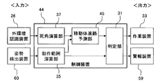
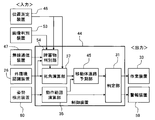
- FIG. 3 is a functional block diagram schematically showing a part of the processing functions of the control device mounted on the hydraulic excavator. Further, FIG. 4 is a functional block diagram showing a part of the functions in FIG. 3 in detail.
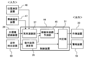
- the control device 44 includes a determination unit 31, an operating range calculation unit 35, a blind spot calculation unit 37, and a moving body course prediction unit 45.
- the operation range calculation unit 35 includes a posture calculation unit 43, a turning angle calculation unit 48, a speed limit area calculation unit 50, a front work machine speed calculation unit 51, and an angular velocity calculation unit 52.
- the speed limit area calculation unit 50 includes a braking distance calculation unit 30 and a braking time calculation unit 49.
- the blind spot calculation unit 37 calculates the blind spot from the relative positional relationship with respect to the upper swivel body 22 obtained from the external environment recognition device 26.
- the operation range calculation unit 35 calculates the braking time based on the information obtained from the posture detection device 60, transmits the braking time to the moving body course prediction unit 45, and transmits the operation range of the main body to the determination unit 31. The calculation performed by the operating range calculation unit 35 will be described in detail later.
- the moving body course prediction unit 45 determines whether or not there is a possibility that a moving body such as a worker is lurking from the position and shape of the obtained blind spot 16, and also determines whether or not a moving body such as a worker may be lurking, and the obtained front work machine 24
- the range in which the moving body can move from the braking time to the braking of the front work machine 24 and the assumed movement range 41 are calculated and transmitted to the determination unit 31.
- the determination unit 31 determines whether to limit the speed of the work device 33 or operate the alarm device 59 based on the information obtained by the moving body course prediction unit 45 and the operation range calculation unit 35. Details of the calculation of the determination unit 31 will be described later.
- the posture calculation unit 43 calculates the length of the front work machine 24 based on the angle information of each of the boom 8, arm 9, and bucket 10 obtained by the posture sensor 34, and transfers to the speed limit area calculation unit 50.
- the front work machine speed calculation unit 51 calculates the speed at which the front work machine 24 moves (front work machine speed) based on the fluctuations in the angles of the boom 8, arm 9, and bucket 10 obtained by the attitude sensor 34. Then, it is transmitted to the speed limit area calculation unit 50.
- the turning angle calculation unit 48 calculates the turning angle of the own vehicle 13 with the front direction of the lower traveling body 20 as 0 ° and the left turning direction of the upper turning body 22 as positive, and transmits the calculation to the speed limiting area calculation unit 50. To do.
- the angular velocity calculation unit 52 calculates the angular velocity of the front working machine 24 based on the change speed of the turning angle input from the turning angle detecting device 27, and transmits the angular velocity to the speed limiting area calculation unit 50.
- the speed limit area calculation unit 50 includes a braking distance calculation unit 30 and a braking time calculation unit 49.
- the braking distance calculation unit 30 includes the front work machine length obtained by the attitude calculation unit 43, the moving speed of the front work machine 24 obtained by the front work machine speed calculation unit 51, and the turning angle obtained by the turning angle calculation unit 48. Then, the braking distance of the front working machine 24 is calculated from the angular velocity obtained from the angular velocity calculation unit 52 and transmitted to the determination unit 31.
- the braking time calculation unit 49 was obtained from the front work machine length obtained by the attitude calculation unit 43, the moving speed of the front work machine 24 obtained from the front work machine speed calculation unit 51, and the turning angle calculation unit 48.
- the braking time of the front working machine 24 is calculated from the turning angle and the angular velocity obtained from the angular velocity calculation unit 52, and transmitted to the moving body course prediction unit 45.
- the control device 44 configured as described above calculates a blind spot range (blind spot 16) that is a blind spot from the recognition range of the external environment recognition device by the object recognized by the external environment recognition device 26, and is assumed to exist in the blind spot.
- the assumed movement range 41 which is the range in which the assumed moving body 39 can move in a predetermined time, is calculated, and the front working machine 24 can move in a predetermined time based on the posture information detected by the posture detecting device 60.
- Preventive control is performed to prevent contact between the moving body 39 and the front working machine 24 based on the assumed moving range 41 of the moving body 39 and the movable range of the front working machine 24 by calculating the movable range which is a wide range. Do.
- FIG. 13 is a flowchart showing the processing content of preventive control.
- control device 44 first determines whether or not there is an obstacle (step S101), and if the determination result is YES, detects the posture of the hydraulic excavator main body (step S102) and causes the obstacle.
- the blind spot range calculation for calculating the generated blind spot is performed (step S103).
- step S104 it is determined whether or not the moving body may hide in the blind spot (step S104), and if the determination result is YES, the braking time calculation for calculating the braking time of the front working machine 24 is performed (step S105). ), The operation range calculation process for calculating the movement range of the front work machine 24 is performed (step S106), and the assumed movement range calculation for calculating the relative movement range of the moving body is performed (step S107).
- step S108 it is determined whether or not there is a possibility that the moving body and the front work machine 24 come into contact with each other (step S108), and if the determination result is YES, the speed limit for driving the front work machine 24 is determined. (Step S109), the alarm device 59 is operated and the working speed is controlled (step S110).
- step S111 determines whether or not it has stopped (step S111), and if the determination result is NO, the process of step S110 is repeated until the determination result becomes YES. If the determination result in step S111 is YES, the process ends.
- the front working machine length R is a distance R from the turning center axis 25 to the tip of the front working machine 24.
- the lengths of the boom 8, the arm 9, and the bucket 10 are L1, L2, and L3, respectively.
- the angle ⁇ 1 formed by the xy plane and the longitudinal direction of the boom 8 is measured by the posture sensor 34A.
- the angle ⁇ 2 formed by the boom 8 and the arm 9 and the angle ⁇ 3 formed by the arm 9 and the bucket 10 are measured by the posture sensors 34B and 34C, respectively.
- the height Z0 from the xy plane to the swing center 38 is determined in advance. Further, the distance L0 from the turning center axis 25 to the swing center 38 is also obtained in advance.
- the angle ⁇ 2a formed by the xy plane and the longitudinal direction of the arm 9 can be calculated.
- the angle ⁇ 3b formed by the xy plane and the longitudinal direction of the bucket 10 can be calculated.
- the bucket height Zb and the front working machine length R can be calculated by the following (Equation 1) and (Equation 2).
- Zb Z0 + L1sin ⁇ 1 + L2sin ⁇ 2 + L3sin ⁇ 3 ...
- R L0 + L1cos ⁇ 1 + L2cos ⁇ 2 + L3cos ⁇ 3 ...
- the calculation method of the blind spot 16 performed by the control device 44 of the first embodiment according to the present invention will be described with reference to FIGS. 5 to 11.
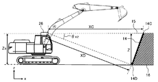
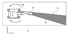
- a blind spot calculation method on the xy plane will be described with reference to FIG.
- the obstacle position calculation unit 36 in the control device 44 uses the own vehicle 13 on the xy plane, the left and right ends 14A of the obstacle 14, and the obstacle 14.
- the relative angles ⁇ xya and ⁇ xyb and the relative distances XA and XB of each of the 14Bs are calculated.
- the blind spot calculation unit 37 calculates whether or not the blind spot 16 exists due to the obstacle 14.
- the blind spot 16 refers to the range indicated by the diagonal line, and when the surface side of the detected obstacle 14 is set to the front, the region behind the position where the obstacle 14 is detected is recognized as the blind spot 16. That is, when the distances from the external environment recognition device 26 to both ends 14A and 14B of the obstacle 14 are XA and XB, respectively, the distances from the external environment recognition device 26 to the ends of the obstacle 14 XA and XB angles ⁇ xy. The area behind the range of is recognized as a blind spot 16. When the size of the blind spot 16 is smaller than that of a general moving body (worker) 39, the blind spot 16 may not be provided. By doing so, excessive control intervention can be avoided.
- the height of the blind spot 16 is defined as the height Z.
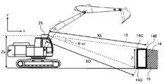
- the distance from the external environment recognition device 26 to the upper and lower ends 14C and 14D of the obstacle 14 is recognized as the blind spot 16 behind the range of the angles ⁇ xz of XC and XD.
- the depth of the obstacle 14 is the end 14C of the obstacle 14. It can be calculated from 14D and 14E.
- the blind spot 16 is the angle between the distances XD and XE to the ends 14D and 14E of the obstacle 14.
- the upper end portion 14C of the obstacle 14 and the external environment recognition device Let ⁇ xza be the angle with the height Zs of 26, let ⁇ xzb be the angle between the lower end 14D of the obstacle 14 and the height Zs of the external environment recognition device 26, and in the range of the angle of ⁇ xzs, which is the sum of ⁇ xza and ⁇ xzb.
- the area behind the obstacle 14 is recognized as a blind spot 16.
- the bucket 10 of the own vehicle 13 may become a blind spot 16 depending on the installation location of the external environment recognition device 26. As shown in FIG. 9, depending on the posture of the hydraulic excavator 100, the bucket 10 blocks the field of view of the external environment recognition device 26 and forms a blind spot 16. In this case, if the external environment recognition device 26 can partially recognize the obstacle 14 through the bucket 10, it is not determined to be the blind spot 16.
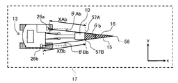
- the blind spot 16 when the external environment recognition device 26 is installed on the upper part of the cab 2, a blind spot 16 is formed also on the xy plane. Therefore, as shown in FIG. 11, for example, by installing the external environment recognition device 26 on the upper swing body 22 on the opposite side of the front working machine 24 when viewed from the cab 2 side, the range of the blind spot 16 can be narrowed. In this case, the blind spot 16 recognizes the point where both blind spot lines 15 of the external environment recognition devices 26a and 26b intersect, the range from the blind spot line intersection 58 to the angle ⁇ b as the blind spot up to the distance between the tip end portions 57A and 57B of the bucket. ..
- the angle ⁇ b is the sum of ⁇ Ab and ⁇ Bb.
- the distance xt (forward braking distance) from the time when the brake for stopping the movement in the forward direction is activated until the front working machine 24 stops is the forward speed v and the movement in the front-rear direction is stopped.
- the speed limiting region 40 has a radius of Rxt when the forward braking distance is xt, the length of the front working machine is R, and the sum value of the distance L0 from the turning center axis 25 to the swing center 38 is Rxt. Is the range obtained by turning ⁇ t. Further, the speed limit region 40 when the front work machine 24 is moving backward is a range in which the radius of the front work machine length R is turned by ⁇ t.
- the assumed movement range 41 of the moving body (worker) 39 is determined by the walking time of the moving body (worker) 39 and the distance r that the moving body (worker) 39 can move. For the walking time of the moving body (worker) 39, a value having a large time until the front working machine 24 brakes in the front-rear direction and the turning direction is selected.
- the distance r that the moving body (worker) 39 can move is such that the moving body (worker) 39 walks for the moving time when the walking speed of the moving body (worker) 39 is taken as the average walking speed of an adult. It is defined as a distance. Therefore, the assumed movement range 41 is a range in which the distance r that the worker can move is rotated by 360 ° from the surface of the moving body (worker) 39.
- the blind spot 16 is formed by the bucket 10
- the blind spot range can be complemented by using the information before forming the blind spot obtained by the external environment recognition device 26, and excessive control can be suppressed.
- the determination unit 31 determines whether or not the assumed movement range 41 calculated by the moving body course prediction unit 45 and the speed limit area 40 calculated by the operation range calculation unit 35 overlap, and the assumed movement range 41 and the operation range calculation unit 35 determine whether or not they overlap.
- the speed limit is transmitted to the work device 33 or the alarm device 59 is activated.
- the probability of contact with a moving body appearing from the blind spot 16 can be reduced.
- a margin is provided in the speed limiting area 40, the alarm device 59 is activated when the assumed movement range 41 overlaps within the margin, and the speed is moved to the working device 33 when the speed limiting area 40 and the assumed movement range 41 are likely to overlap. It is also possible to enforce restrictions.
- a main body including a lower traveling body and an upper rotating body provided so as to be rotatable with respect to the lower traveling body, and a plurality of bodies attached to the main body and rotatably connected.
- the front members are provided on the front members of the front working machine.
- a posture detection device that detects posture information, an external environment recognition device that detects objects around the main body, and a blind spot range that is a blind spot from the recognition range of the external environment recognition device by the object recognized by the external environment recognition device.
- the assumed movement range which is the range in which the moving body assumed to exist in the blind spot can move in a predetermined time
- the movable range which is the movable range in time
- preventive control is performed to prevent contact between the moving body and the front working machine based on the assumed moving range of the moving body and the movable range of the front working machine. Since it is configured to be provided with a control device, it is possible to sufficiently cope with a moving body in a blind spot of an object, and it is possible to more reliably prevent contact between the front working machine and the moving body.
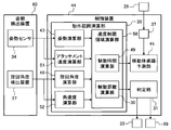
- the blind spot 16 is calculated from the relative distance and the relative angle with the obstacle 14 by using the external environment recognition device 26, but in the present embodiment, for example, based on a GPS signal or the like.
- a wireless communication device including a position measuring device 46 for measuring the position of the own vehicle 13 and a wireless communication device 47 for receiving information on the position of an obstacle 14 detected by the other vehicle 18, the position of the other vehicle 18, and the orientation of the main body. 47 transmits the information obtained from the other vehicle 18 to the blind spot calculation unit 37, and the blind spot calculation unit 37 sets the blind spot 16 and the moving body based on the information of the external environment recognition device 26, the position measuring device 46 and the wireless communication device 47. Is calculated for the position where is possible and the assumed movement range 41 of the moving body (worker) 39.
- FIG. 14 is a functional block diagram schematically showing a part of the processing functions of the control device mounted on the hydraulic excavator according to the present embodiment. Further, FIG. 15 is a diagram illustrating the calculation of the blind spot in the present embodiment. In the figure, the same members as those in the first embodiment are designated by the same reference numerals, and the description thereof will be omitted.
- the position measuring device 46 transmits the coordinate position of the own vehicle 13 to the blind spot calculation unit 37 based on, for example, a GPS signal.
- the wireless communication device 47 receives the information of the external environment recognition device 26 obtained by the other vehicle 18, the coordinate position of the other vehicle 18, and the orientation of the main body of the other vehicle 18 and transmits the information to the blind spot calculation unit 37.
- the blind spot calculation unit 37 calculates the blind spot 16 based on the information of the position measuring device 46, the wireless communication device 47, and the external environment recognition device 26 of the own vehicle 13, and transmits the blind spot 16 to the moving body course prediction unit 45.
- the other vehicle 18 when the other vehicle 18 is present at a position where the side of the obstacle 14 can be detected from inside and outside the working range 17, the other vehicle 18 has the coordinate position of the vehicle, the orientation of the main body, and the outside.
- the information of the environment recognition device 26 is transmitted via the wireless communication device 47.
- the own vehicle 13 receives the information obtained by the other vehicle 18 via the wireless communication device 47, and the blind spot calculation unit 37 calculates the positional relationship between the own vehicle 13 and the other vehicle 18 from the coordinate positions of the own vehicle 13 and the other vehicle 18. To do. Further, the position of the obstacle 14 and the blind spot 16 detected by the other vehicle 18 are calculated from the orientation of the main body of the other vehicle 18.
- the blind spot 16 of the obstacle 14 detected by the own vehicle 13 is represented by the range of the blind spot line 15a
- the blind spot 16 of the obstacle 14 detected by the other vehicle 18 is represented by the range of the blind spot line 15b.
- the blind spot calculation unit 37 compares the blind spot 16 calculated based on the information obtained by the own vehicle 13 with the blind spot 16 calculated based on the information of the other vehicle 18, and determines the range as the blind spot 16 by the own vehicle 13. If the other vehicle 18 can detect the above, the range is not recognized as the blind spot 16. As a result, it is not necessary to limit the speed for the work and the turning motion in the direction detected by the other vehicle 18.
- the technique of acquiring coordinate data such as LiDAR is used in the external environment recognition device 26 to obtain the relative distance and the relative angle to the obstacle 14, and further, the position of the own vehicle 13 is measured.
- the blind spot 16 was calculated from the position information of the other vehicle 18 obtained from the position measuring device 46 and the wireless communication device 47, the relative distance to the obstacle 14, and the relative angle.
- the own vehicle 13 A position estimation device for measuring a position, an image discrimination device 53 for photographing an object 14 using a camera or the like, a wireless communication device 47 for receiving information from another vehicle 18 via wireless communication, and an obstacle 14.
- the object determination unit 54 is equipped with an external environment recognition device 26 that transmits relative distance and relative angle to the obstacle determination unit 54, and an obstacle determination unit 54 that determines the obstacle 14 based on the information, and the obstacle is based on the information.
- the object determination unit 54 additionally implements a function of recognizing the obstacle 14 as another vehicle 18 and determining the vehicle type.
- FIG. 16 is a functional block diagram schematically showing a part of the processing functions of the control device mounted on the hydraulic excavator according to the present embodiment. Further, FIG. 17 is a diagram for explaining the calculation of the blind spot in the present embodiment, and FIG. 18 is a diagram for explaining the assumed transfer range of the moving body in the present embodiment. In the figure, the same members as those in the first and second embodiments are designated by the same reference numerals, and the description thereof will be omitted.
- the position measuring device 46 transmits the coordinates of the own vehicle 13 to the obstacle determination unit 54.
- the image discrimination device 53 photographs the obstacle 14 and transmits it to the obstacle discrimination unit 54.
- the wireless communication device 47 transmits the position information and the vehicle type information of the other vehicle 18 equipped with the position measuring device 46 to the obstacle determination unit 54.
- the obstacle discriminating unit 54 compares the image of the construction machine stored in advance with the image obtained from the image discriminating device 53, and discriminates whether or not the obstacle 14 is another vehicle 18. Further, the obstacle determination unit 54 calculates the positional relationship between the own vehicle 13 and the other vehicle 18 from the position of the own vehicle 13 obtained from the position measuring device 46 and the position information of the other vehicle 18 obtained from the wireless communication device 47. If the position of the obstacle 14 obtained from the external environment recognition device 26 matches the calculated position of the other vehicle 18, the obstacle 14 is recognized as the other vehicle 18.
- the type of the obstacle 14 can be discriminated by using the image discriminating device 53 and the obstacle discriminating unit 54, a certain distance behind is regarded as the obstacle 14 and the blind spot 16 is narrowed. be able to. As a result, the position where the moving body (worker) 39 may exist can be narrowed, and the probability that the assumed moving range 41 of the moving body (worker) 39 overlaps with the speed limiting area 40 can be reduced.
- the position of the moving body (worker) 39 existing in the blind spot 16 is the position closest to the own vehicle 13 in contact with the side surface 56 of the obstacle 14 and the blind spot line 15. Suppose it exists in. Further, when it is difficult to determine the obstacle 14, or when the obstacle 14 is not registered, the range of the blind spot is determined according to the blind spot detection method of the first embodiment.
- the present invention is not limited to the above-described embodiments, and various modifications and combinations are included within the scope of the invention. Further, the present invention is not limited to the one provided with all the configurations described in the above-described embodiments, and includes one obtained by deleting a part of the configuration. Further, the above-mentioned respective configurations, functions and the like may be realized by partially or entirely designing, for example, an integrated circuit. Further, each of the above configurations, functions, and the like may be realized by software by the processor interpreting and executing a program that realizes each function.
Landscapes
- Engineering & Computer Science (AREA)
- Mining & Mineral Resources (AREA)
- Civil Engineering (AREA)
- General Engineering & Computer Science (AREA)
- Structural Engineering (AREA)
- Mechanical Engineering (AREA)
- Computer Networks & Wireless Communication (AREA)
- Signal Processing (AREA)
- Human Computer Interaction (AREA)
- Operation Control Of Excavators (AREA)
- Component Parts Of Construction Machinery (AREA)
Priority Applications (4)
| Application Number | Priority Date | Filing Date | Title |
|---|---|---|---|
| KR1020217027634A KR102579791B1 (ko) | 2019-03-14 | 2020-02-14 | 건설 기계 |
| CN202080017560.1A CN113508206B (zh) | 2019-03-14 | 2020-02-14 | 工程机械 |
| US17/422,643 US20210388578A1 (en) | 2019-03-14 | 2020-02-14 | Construction machine |
| EP20770062.6A EP3904609B1 (en) | 2019-03-14 | 2020-02-14 | Construction machine |
Applications Claiming Priority (2)
| Application Number | Priority Date | Filing Date | Title |
|---|---|---|---|
| JP2019-047081 | 2019-03-14 | ||
| JP2019047081A JP7111641B2 (ja) | 2019-03-14 | 2019-03-14 | 建設機械 |
Publications (1)
| Publication Number | Publication Date |
|---|---|
| WO2020184065A1 true WO2020184065A1 (ja) | 2020-09-17 |
Family
ID=72426792
Family Applications (1)
| Application Number | Title | Priority Date | Filing Date |
|---|---|---|---|
| PCT/JP2020/005800 WO2020184065A1 (ja) | 2019-03-14 | 2020-02-14 | 建設機械 |
Country Status (6)
| Country | Link |
|---|---|
| US (1) | US20210388578A1 (ko) |
| EP (1) | EP3904609B1 (ko) |
| JP (1) | JP7111641B2 (ko) |
| KR (1) | KR102579791B1 (ko) |
| CN (1) | CN113508206B (ko) |
| WO (1) | WO2020184065A1 (ko) |
Cited By (1)
| Publication number | Priority date | Publication date | Assignee | Title |
|---|---|---|---|---|
| EP4224452A4 (en) * | 2020-09-29 | 2024-03-06 | Sony Semiconductor Solutions Corp | INFORMATION PROCESSING SYSTEM AND INFORMATION PROCESSING METHOD |
Families Citing this family (1)
| Publication number | Priority date | Publication date | Assignee | Title |
|---|---|---|---|---|
| US11898331B2 (en) * | 2020-12-02 | 2024-02-13 | Caterpillar Sarl | System and method for detecting objects within a working area |
Citations (7)
| Publication number | Priority date | Publication date | Assignee | Title |
|---|---|---|---|---|
| JP2011028729A (ja) * | 2009-07-03 | 2011-02-10 | Takenaka Komuten Co Ltd | 接触防止システム、建設機械およびプログラム |
| JP2012021290A (ja) | 2010-07-13 | 2012-02-02 | Sumitomo Heavy Ind Ltd | 旋回作業機械及び旋回作業機械の制御方法 |
| JP2016024685A (ja) * | 2014-07-22 | 2016-02-08 | 日立建機株式会社 | 鉱山用作業車両 |
| WO2018008542A1 (ja) * | 2016-07-05 | 2018-01-11 | 住友建機株式会社 | ショベル |
| JP2018093501A (ja) * | 2018-01-04 | 2018-06-14 | 住友重機械工業株式会社 | 作業機械 |
| JP2018172943A (ja) * | 2017-03-31 | 2018-11-08 | コベルコ建機株式会社 | 干渉監視装置 |
| WO2019039593A1 (ja) * | 2017-08-24 | 2019-02-28 | 日立建機株式会社 | 作業機械 |
Family Cites Families (10)
| Publication number | Priority date | Publication date | Assignee | Title |
|---|---|---|---|---|
| JP2753778B2 (ja) * | 1991-10-24 | 1998-05-20 | 株式会社フジタ | 建設作業車の自動制御装置 |
| JP4108412B2 (ja) * | 2002-08-19 | 2008-06-25 | 株式会社小松製作所 | 作業車両 |
| EP2615596A4 (en) * | 2010-09-08 | 2017-12-06 | Toyota Jidosha Kabushiki Kaisha | Moving-object prediction device, virtual-mobile-object prediction device, program, mobile-object prediction method, and virtual-mobile-object prediction method |
| JP5573617B2 (ja) * | 2010-11-12 | 2014-08-20 | トヨタ自動車株式会社 | 危険度算出装置 |
| US9975485B2 (en) * | 2014-04-25 | 2018-05-22 | Komatsu Ltd. | Surroundings monitoring system, work vehicle, and surroundings monitoring method |
| CN106575474A (zh) * | 2014-07-28 | 2017-04-19 | 三菱电机株式会社 | 行驶辅助系统及行驶辅助方法 |
| JP2016122308A (ja) * | 2014-12-25 | 2016-07-07 | クラリオン株式会社 | 車両制御装置 |
| JP6581139B2 (ja) * | 2017-03-31 | 2019-09-25 | 日立建機株式会社 | 作業機械の周囲監視装置 |
| JP7163729B2 (ja) * | 2018-11-08 | 2022-11-01 | トヨタ自動車株式会社 | 車両制御装置 |
| JP7180436B2 (ja) * | 2019-02-15 | 2022-11-30 | 株式会社デンソー | 行動制御方法、及び行動制御装置 |
-
2019
- 2019-03-14 JP JP2019047081A patent/JP7111641B2/ja active Active
-
2020
- 2020-02-14 WO PCT/JP2020/005800 patent/WO2020184065A1/ja unknown
- 2020-02-14 EP EP20770062.6A patent/EP3904609B1/en active Active
- 2020-02-14 US US17/422,643 patent/US20210388578A1/en active Pending
- 2020-02-14 KR KR1020217027634A patent/KR102579791B1/ko active IP Right Grant
- 2020-02-14 CN CN202080017560.1A patent/CN113508206B/zh active Active
Patent Citations (7)
| Publication number | Priority date | Publication date | Assignee | Title |
|---|---|---|---|---|
| JP2011028729A (ja) * | 2009-07-03 | 2011-02-10 | Takenaka Komuten Co Ltd | 接触防止システム、建設機械およびプログラム |
| JP2012021290A (ja) | 2010-07-13 | 2012-02-02 | Sumitomo Heavy Ind Ltd | 旋回作業機械及び旋回作業機械の制御方法 |
| JP2016024685A (ja) * | 2014-07-22 | 2016-02-08 | 日立建機株式会社 | 鉱山用作業車両 |
| WO2018008542A1 (ja) * | 2016-07-05 | 2018-01-11 | 住友建機株式会社 | ショベル |
| JP2018172943A (ja) * | 2017-03-31 | 2018-11-08 | コベルコ建機株式会社 | 干渉監視装置 |
| WO2019039593A1 (ja) * | 2017-08-24 | 2019-02-28 | 日立建機株式会社 | 作業機械 |
| JP2018093501A (ja) * | 2018-01-04 | 2018-06-14 | 住友重機械工業株式会社 | 作業機械 |
Cited By (1)
| Publication number | Priority date | Publication date | Assignee | Title |
|---|---|---|---|---|
| EP4224452A4 (en) * | 2020-09-29 | 2024-03-06 | Sony Semiconductor Solutions Corp | INFORMATION PROCESSING SYSTEM AND INFORMATION PROCESSING METHOD |
Also Published As
| Publication number | Publication date |
|---|---|
| EP3904609A4 (en) | 2022-11-09 |
| KR20210120085A (ko) | 2021-10-06 |
| CN113508206B (zh) | 2023-01-10 |
| EP3904609A1 (en) | 2021-11-03 |
| EP3904609B1 (en) | 2024-01-17 |
| US20210388578A1 (en) | 2021-12-16 |
| JP2020148029A (ja) | 2020-09-17 |
| JP7111641B2 (ja) | 2022-08-02 |
| KR102579791B1 (ko) | 2023-09-19 |
| CN113508206A (zh) | 2021-10-15 |
Similar Documents
| Publication | Publication Date | Title |
|---|---|---|
| EP3409843B1 (en) | Working machine | |
| JP7358349B2 (ja) | 掘削機、情報処理装置 | |
| CN112513378B (zh) | 作业机械 | |
| JP7114248B2 (ja) | 建設機械 | |
| WO2020170687A1 (ja) | 安全装置及び建設機械 | |
| WO2019189031A1 (ja) | ショベル | |
| WO2020184065A1 (ja) | 建設機械 | |
| WO2020166241A1 (ja) | 監視装置及び建設機械 | |
| WO2021192655A1 (ja) | 作業機械 | |
| CN114867922B (zh) | 作业机械以及控制系统 | |
| JP7222775B2 (ja) | 作業機械 | |
| WO2020255970A1 (ja) | 作業機械 | |
| WO2021029253A1 (ja) | 作業機械 | |
| JP7491787B2 (ja) | 作業機械の制御システムおよび作業機械の制御方法 | |
| WO2022030286A1 (ja) | 作業機械の制御システム | |
| WO2021066057A1 (ja) | 侵入監視制御システムおよび作業機械 | |
| JP2023145210A (ja) | 作業機械 | |
| JP2024030384A (ja) | 作業機械の安全装置 | |
| JP2021050583A (ja) | 作業機械 |
Legal Events
| Date | Code | Title | Description |
|---|---|---|---|
| 121 | Ep: the epo has been informed by wipo that ep was designated in this application |
Ref document number: 20770062 Country of ref document: EP Kind code of ref document: A1 |
|
| ENP | Entry into the national phase |
Ref document number: 2020770062 Country of ref document: EP Effective date: 20210727 |
|
| ENP | Entry into the national phase |
Ref document number: 20217027634 Country of ref document: KR Kind code of ref document: A |
|
| NENP | Non-entry into the national phase |
Ref country code: DE |