WO2020184065A1 - 建設機械 - Google Patents
建設機械 Download PDFInfo
- Publication number
- WO2020184065A1 WO2020184065A1 PCT/JP2020/005800 JP2020005800W WO2020184065A1 WO 2020184065 A1 WO2020184065 A1 WO 2020184065A1 JP 2020005800 W JP2020005800 W JP 2020005800W WO 2020184065 A1 WO2020184065 A1 WO 2020184065A1
- Authority
- WO
- WIPO (PCT)
- Prior art keywords
- range
- blind spot
- construction machine
- environment recognition
- machine
- Prior art date
Links
Images


Classifications
-
- E—FIXED CONSTRUCTIONS
- E02—HYDRAULIC ENGINEERING; FOUNDATIONS; SOIL SHIFTING
- E02F—DREDGING; SOIL-SHIFTING
- E02F9/00—Component parts of dredgers or soil-shifting machines, not restricted to one of the kinds covered by groups E02F3/00 - E02F7/00
- E02F9/20—Drives; Control devices
-
- E—FIXED CONSTRUCTIONS
- E02—HYDRAULIC ENGINEERING; FOUNDATIONS; SOIL SHIFTING
- E02F—DREDGING; SOIL-SHIFTING
- E02F9/00—Component parts of dredgers or soil-shifting machines, not restricted to one of the kinds covered by groups E02F3/00 - E02F7/00
- E02F9/26—Indicating devices
- E02F9/261—Surveying the work-site to be treated
- E02F9/262—Surveying the work-site to be treated with follow-up actions to control the work tool, e.g. controller
-
- B—PERFORMING OPERATIONS; TRANSPORTING
- B60—VEHICLES IN GENERAL
- B60Q—ARRANGEMENT OF SIGNALLING OR LIGHTING DEVICES, THE MOUNTING OR SUPPORTING THEREOF OR CIRCUITS THEREFOR, FOR VEHICLES IN GENERAL
- B60Q9/00—Arrangement or adaptation of signal devices not provided for in one of main groups B60Q1/00 - B60Q7/00, e.g. haptic signalling
- B60Q9/008—Arrangement or adaptation of signal devices not provided for in one of main groups B60Q1/00 - B60Q7/00, e.g. haptic signalling for anti-collision purposes
-
- E—FIXED CONSTRUCTIONS
- E02—HYDRAULIC ENGINEERING; FOUNDATIONS; SOIL SHIFTING
- E02F—DREDGING; SOIL-SHIFTING
- E02F3/00—Dredgers; Soil-shifting machines
- E02F3/04—Dredgers; Soil-shifting machines mechanically-driven
- E02F3/28—Dredgers; Soil-shifting machines mechanically-driven with digging tools mounted on a dipper- or bucket-arm, i.e. there is either one arm or a pair of arms, e.g. dippers, buckets
- E02F3/30—Dredgers; Soil-shifting machines mechanically-driven with digging tools mounted on a dipper- or bucket-arm, i.e. there is either one arm or a pair of arms, e.g. dippers, buckets with a dipper-arm pivoted on a cantilever beam, i.e. boom
- E02F3/32—Dredgers; Soil-shifting machines mechanically-driven with digging tools mounted on a dipper- or bucket-arm, i.e. there is either one arm or a pair of arms, e.g. dippers, buckets with a dipper-arm pivoted on a cantilever beam, i.e. boom working downwardly and towards the machine, e.g. with backhoes
-
- E—FIXED CONSTRUCTIONS
- E02—HYDRAULIC ENGINEERING; FOUNDATIONS; SOIL SHIFTING
- E02F—DREDGING; SOIL-SHIFTING
- E02F9/00—Component parts of dredgers or soil-shifting machines, not restricted to one of the kinds covered by groups E02F3/00 - E02F7/00
- E02F9/20—Drives; Control devices
- E02F9/2025—Particular purposes of control systems not otherwise provided for
- E02F9/2033—Limiting the movement of frames or implements, e.g. to avoid collision between implements and the cabin
-
- E—FIXED CONSTRUCTIONS
- E02—HYDRAULIC ENGINEERING; FOUNDATIONS; SOIL SHIFTING
- E02F—DREDGING; SOIL-SHIFTING
- E02F9/00—Component parts of dredgers or soil-shifting machines, not restricted to one of the kinds covered by groups E02F3/00 - E02F7/00
- E02F9/24—Safety devices, e.g. for preventing overload
-
- E—FIXED CONSTRUCTIONS
- E02—HYDRAULIC ENGINEERING; FOUNDATIONS; SOIL SHIFTING
- E02F—DREDGING; SOIL-SHIFTING
- E02F9/00—Component parts of dredgers or soil-shifting machines, not restricted to one of the kinds covered by groups E02F3/00 - E02F7/00
- E02F9/26—Indicating devices
-
- H—ELECTRICITY
- H04—ELECTRIC COMMUNICATION TECHNIQUE
- H04W—WIRELESS COMMUNICATION NETWORKS
- H04W4/00—Services specially adapted for wireless communication networks; Facilities therefor
- H04W4/02—Services making use of location information
- H04W4/023—Services making use of location information using mutual or relative location information between multiple location based services [LBS] targets or of distance thresholds
Definitions
- the present invention relates to construction machinery.
- Patent Document 1 In construction machines such as hydraulic excavators in the construction and civil engineering construction industry, as a means of preventing contact between a front work machine performing work and a worker, for example, the working speed of the front work machine is set as described in Patent Document 1. There is a technology to control.
- Patent Document 1 describes an attachment rotatably attached to a traveling body (base), a swivel mechanism for swiveling the attachment, a control device for controlling the swivel mechanism, and a position of an approaching object that has entered the work area.
- the control device has a first physical quantity related to at least one of the current angular velocity of the attachment and the current moment of inertia of the attachment, and the approaching object detected by the approaching object detecting device.
- a swivel work machine that controls the swivel motion of an attachment based on its position is disclosed.
- the present invention has been made in view of the above, and a construction machine capable of dealing with a moving body in a blind spot of an object and more reliably preventing contact between a front working machine and a moving body.
- the purpose is to provide.
- the present application includes a plurality of means for solving the above problems, and to give an example thereof, a main body including a lower traveling body, an upper rotating body provided so as to be rotatable with respect to the lower traveling body, and the above.
- a posture detecting device provided on the front member of the front working machine to detect the posture information of the front member, an external environment recognition device for detecting an object around the main body, and the external environment recognition device recognize the machine.
- the blind spot range which is the range of the blind spot
- the assumed movement range which is the range in which the moving body assumed to exist in the blind spot can move in a predetermined time
- the movable range which is the range in which the front work machine can move in a predetermined time
- a control device for performing preventive control for preventing contact between the moving body and the front working machine is provided based on the movable range of the machine.
- the present invention it is possible to sufficiently cope with a moving body in a blind spot of an object, and it is possible to more reliably prevent contact between the front working machine and the moving body.
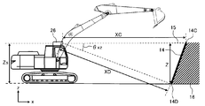
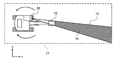
- FIG. 1 is a diagram schematically showing the appearance of a hydraulic excavator which is an example of a construction machine according to the present embodiment. Further, FIG. 2 is a side view schematically showing the appearance of the hydraulic excavator.
- the hydraulic excavator 100 is configured by connecting a plurality of driven members (boom 8, arm 9, bucket (working tool) 10) that rotate in the vertical direction, respectively. It includes an articulated front working machine 24, an upper swivel body 22 and a lower traveling body 20 constituting an excavator main body (hereinafter, simply referred to as “main body”), and the upper swivel body 22 travels downward via a swivel mechanism 21. It is provided so as to be rotatable with respect to the body 20.
- the swivel mechanism 21 has a swivel motor 23 and a swivel angle detection device 27.
- the swivel motor 23 swivels the upper swivel body 22 with respect to the lower traveling body 20, and the swivel angle detecting device 27 swivels the lower traveling body. The turning angle with respect to 20 is detected.
- the base end of the boom 8 of the front working machine 24 is vertically rotatably supported by the front portion of the upper swing body 22, and one end of the arm 9 is at an end (tip) different from the base end of the boom 8. It is rotatably supported in the vertical direction, and the bucket 10 is rotatably supported in the vertical direction at the other end of the arm 9.
- the boom 8, arm 9, bucket 10, upper swing body 22, and lower traveling body 20 are hydraulic actuators such as a boom cylinder 5, an arm cylinder 6, a bucket cylinder 7, a swing motor 23, and left and right traveling motors 3 (however, the left and right traveling motors 3). Only one traveling motor is shown).
- the z-axis whose origin is the intersection of the turning center axis 25 of the upper turning body 22 and the lower surface of the upper turning body 22 and whose upper side is positive along the turning center axis 25 is perpendicular to the z-axis from the origin.
- a main body coordinate system is set having an x-axis having a positive front in the front-rear direction and a positive y-axis in the left-right direction perpendicular to the z-axis and the x-axis from the origin.
- the cab 2 on which the operator is boarding is mounted on the front left side of the upper swivel body 22. Further, a control device 44 for controlling the overall operation of the hydraulic excavator 100 is arranged on the upper swing body 22.
- the cab 2 is provided with operation levers (operation devices) 2a and 2b that output operation signals for operating the hydraulic actuators 5 to 7, 23.
- the operating levers 2a and 2b can be tilted back and forth and left and right, respectively, and include a detection device (not shown) that electrically detects the tilting amount of the lever, which is an operation signal, that is, the lever operating amount.
- the lever operation amount is output to the control device 44 (described later) via electrical wiring. That is, the operations of the hydraulic actuators 5 to 7 and 23 are assigned to the operation levers 2a and 2b in the front-rear direction or the left-right direction, respectively.
- the operation control of the boom cylinder 5, arm cylinder 6, bucket cylinder 7, swivel motor 23, and left and right traveling motors 3 is performed by hydraulic actuators 3, 5 to each from a hydraulic pump device driven by a prime mover such as an engine or an electric motor (not shown). This is done by controlling the direction and flow rate of the hydraulic oil supplied to 7 and 23 with a control valve or the like.
- the operation of the control valve is controlled by the control device 44 based on the operation signals from the operation levers 2a and 2b, whereby the operations of the hydraulic actuators 5 to 7 and 23 are controlled.
- Posture sensors 34A, 34B, and 34C are attached to the base of the boom 8, the connection between the boom 8 and the arm 9, and the connection between the arm 9 and the bucket 10, respectively.
- the attitude sensors 34A, 34B, 34C are mechanical angle sensors such as potentiometers, for example.
- the posture sensor 34A measures the angle ⁇ 1 formed by the longitudinal direction of the boom 8 (a straight line connecting the rotation centers at both ends) and the xy plane and transmits the angle ⁇ 1 to the control device 44.
- the attitude sensor 34B measures the angle ⁇ 2 formed by the longitudinal direction of the boom 8 (straight line connecting the rotation centers at both ends) and the longitudinal direction of the arm 9 (straight line connecting the rotation centers at both ends), and the control device 44.
- the attitude sensor 34C measures the angle ⁇ 3 formed by the longitudinal direction of the arm 9 (the straight line connecting the rotation centers at both ends) and the longitudinal direction of the bucket 10 (the straight line connecting the rotation centers and the toes), and the control device 44.
- the turning angle detecting device 27 and the posture sensors 34A to 34C constitute a posture detecting device 60 that detects the posture information of the upper turning body 22 and the front working machine 24.
- the swing center 38 of the front work machine 24 (the connection portion of the boom 8 with the upper swing body 22) is arranged at a position different from the swing center shaft 25 is illustrated.
- the rotation center axis 25 and the swing center 38 may be arranged so as to intersect with each other.
- the inertial measurement unit (IMU: Inertial Measurement Unit) is used as the turning angle detection device 27 and the attitude sensors 34A to 34C. ) May be used.
- stroke sensors are arranged in the boom cylinder 5, the arm cylinder 6, and the bucket cylinder 7, respectively, and the relative orientations of the upper swing body 22, the boom 8, the arm 9, and the bucket 10 are relative to each other based on the stroke change amount.
- the posture information may be calculated, and each angle may be obtained from the result.
- a plurality of (for example, four) external environment recognition devices 26 for detecting objects around the shovel main body (upper swing body 22, lower traveling body 20) are arranged on the upper swing body 22.
- the installation position and number of the external environment recognition device 26 are not particularly limited to the example of the present embodiment, and it is sufficient that the field of view in all directions of the main body (that is, 360 degrees around the hydraulic excavator 100) can be secured.
- four external environment recognition devices 26 are installed at the upper part of the cab 2, the left side, the right side front part, and the right side rear part of the upper swing body 22, respectively, and are 360 degrees around the main body. The case where the field of view is covered will be described as an example.
- the external environment recognition device 26 is, for example, a sensor using LiDAR (Laser Imaging Detection and Langing) technology, and can detect an object (for example, an obstacle 14 described later) around the hydraulic excavator 100. Detect and transmit the coordinate data to the control device 44.
- LiDAR Laser Imaging Detection and Langing
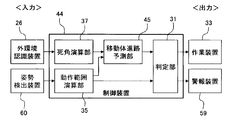
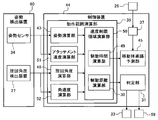
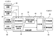
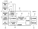
- FIG. 3 is a functional block diagram schematically showing a part of the processing functions of the control device mounted on the hydraulic excavator. Further, FIG. 4 is a functional block diagram showing a part of the functions in FIG. 3 in detail.
- the control device 44 includes a determination unit 31, an operating range calculation unit 35, a blind spot calculation unit 37, and a moving body course prediction unit 45.
- the operation range calculation unit 35 includes a posture calculation unit 43, a turning angle calculation unit 48, a speed limit area calculation unit 50, a front work machine speed calculation unit 51, and an angular velocity calculation unit 52.
- the speed limit area calculation unit 50 includes a braking distance calculation unit 30 and a braking time calculation unit 49.
- the blind spot calculation unit 37 calculates the blind spot from the relative positional relationship with respect to the upper swivel body 22 obtained from the external environment recognition device 26.
- the operation range calculation unit 35 calculates the braking time based on the information obtained from the posture detection device 60, transmits the braking time to the moving body course prediction unit 45, and transmits the operation range of the main body to the determination unit 31. The calculation performed by the operating range calculation unit 35 will be described in detail later.
- the moving body course prediction unit 45 determines whether or not there is a possibility that a moving body such as a worker is lurking from the position and shape of the obtained blind spot 16, and also determines whether or not a moving body such as a worker may be lurking, and the obtained front work machine 24
- the range in which the moving body can move from the braking time to the braking of the front work machine 24 and the assumed movement range 41 are calculated and transmitted to the determination unit 31.
- the determination unit 31 determines whether to limit the speed of the work device 33 or operate the alarm device 59 based on the information obtained by the moving body course prediction unit 45 and the operation range calculation unit 35. Details of the calculation of the determination unit 31 will be described later.
- the posture calculation unit 43 calculates the length of the front work machine 24 based on the angle information of each of the boom 8, arm 9, and bucket 10 obtained by the posture sensor 34, and transfers to the speed limit area calculation unit 50.
- the front work machine speed calculation unit 51 calculates the speed at which the front work machine 24 moves (front work machine speed) based on the fluctuations in the angles of the boom 8, arm 9, and bucket 10 obtained by the attitude sensor 34. Then, it is transmitted to the speed limit area calculation unit 50.
- the turning angle calculation unit 48 calculates the turning angle of the own vehicle 13 with the front direction of the lower traveling body 20 as 0 ° and the left turning direction of the upper turning body 22 as positive, and transmits the calculation to the speed limiting area calculation unit 50. To do.
- the angular velocity calculation unit 52 calculates the angular velocity of the front working machine 24 based on the change speed of the turning angle input from the turning angle detecting device 27, and transmits the angular velocity to the speed limiting area calculation unit 50.
- the speed limit area calculation unit 50 includes a braking distance calculation unit 30 and a braking time calculation unit 49.
- the braking distance calculation unit 30 includes the front work machine length obtained by the attitude calculation unit 43, the moving speed of the front work machine 24 obtained by the front work machine speed calculation unit 51, and the turning angle obtained by the turning angle calculation unit 48. Then, the braking distance of the front working machine 24 is calculated from the angular velocity obtained from the angular velocity calculation unit 52 and transmitted to the determination unit 31.
- the braking time calculation unit 49 was obtained from the front work machine length obtained by the attitude calculation unit 43, the moving speed of the front work machine 24 obtained from the front work machine speed calculation unit 51, and the turning angle calculation unit 48.
- the braking time of the front working machine 24 is calculated from the turning angle and the angular velocity obtained from the angular velocity calculation unit 52, and transmitted to the moving body course prediction unit 45.
- the control device 44 configured as described above calculates a blind spot range (blind spot 16) that is a blind spot from the recognition range of the external environment recognition device by the object recognized by the external environment recognition device 26, and is assumed to exist in the blind spot.
- the assumed movement range 41 which is the range in which the assumed moving body 39 can move in a predetermined time, is calculated, and the front working machine 24 can move in a predetermined time based on the posture information detected by the posture detecting device 60.
- Preventive control is performed to prevent contact between the moving body 39 and the front working machine 24 based on the assumed moving range 41 of the moving body 39 and the movable range of the front working machine 24 by calculating the movable range which is a wide range. Do.
- FIG. 13 is a flowchart showing the processing content of preventive control.
- control device 44 first determines whether or not there is an obstacle (step S101), and if the determination result is YES, detects the posture of the hydraulic excavator main body (step S102) and causes the obstacle.
- the blind spot range calculation for calculating the generated blind spot is performed (step S103).
- step S104 it is determined whether or not the moving body may hide in the blind spot (step S104), and if the determination result is YES, the braking time calculation for calculating the braking time of the front working machine 24 is performed (step S105). ), The operation range calculation process for calculating the movement range of the front work machine 24 is performed (step S106), and the assumed movement range calculation for calculating the relative movement range of the moving body is performed (step S107).
- step S108 it is determined whether or not there is a possibility that the moving body and the front work machine 24 come into contact with each other (step S108), and if the determination result is YES, the speed limit for driving the front work machine 24 is determined. (Step S109), the alarm device 59 is operated and the working speed is controlled (step S110).
- step S111 determines whether or not it has stopped (step S111), and if the determination result is NO, the process of step S110 is repeated until the determination result becomes YES. If the determination result in step S111 is YES, the process ends.
- the front working machine length R is a distance R from the turning center axis 25 to the tip of the front working machine 24.
- the lengths of the boom 8, the arm 9, and the bucket 10 are L1, L2, and L3, respectively.
- the angle ⁇ 1 formed by the xy plane and the longitudinal direction of the boom 8 is measured by the posture sensor 34A.
- the angle ⁇ 2 formed by the boom 8 and the arm 9 and the angle ⁇ 3 formed by the arm 9 and the bucket 10 are measured by the posture sensors 34B and 34C, respectively.
- the height Z0 from the xy plane to the swing center 38 is determined in advance. Further, the distance L0 from the turning center axis 25 to the swing center 38 is also obtained in advance.
- the angle ⁇ 2a formed by the xy plane and the longitudinal direction of the arm 9 can be calculated.
- the angle ⁇ 3b formed by the xy plane and the longitudinal direction of the bucket 10 can be calculated.
- the bucket height Zb and the front working machine length R can be calculated by the following (Equation 1) and (Equation 2).
- Zb Z0 + L1sin ⁇ 1 + L2sin ⁇ 2 + L3sin ⁇ 3 ...
- R L0 + L1cos ⁇ 1 + L2cos ⁇ 2 + L3cos ⁇ 3 ...
- the calculation method of the blind spot 16 performed by the control device 44 of the first embodiment according to the present invention will be described with reference to FIGS. 5 to 11.
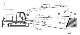
- a blind spot calculation method on the xy plane will be described with reference to FIG.
- the obstacle position calculation unit 36 in the control device 44 uses the own vehicle 13 on the xy plane, the left and right ends 14A of the obstacle 14, and the obstacle 14.
- the relative angles ⁇ xya and ⁇ xyb and the relative distances XA and XB of each of the 14Bs are calculated.
- the blind spot calculation unit 37 calculates whether or not the blind spot 16 exists due to the obstacle 14.
- the blind spot 16 refers to the range indicated by the diagonal line, and when the surface side of the detected obstacle 14 is set to the front, the region behind the position where the obstacle 14 is detected is recognized as the blind spot 16. That is, when the distances from the external environment recognition device 26 to both ends 14A and 14B of the obstacle 14 are XA and XB, respectively, the distances from the external environment recognition device 26 to the ends of the obstacle 14 XA and XB angles ⁇ xy. The area behind the range of is recognized as a blind spot 16. When the size of the blind spot 16 is smaller than that of a general moving body (worker) 39, the blind spot 16 may not be provided. By doing so, excessive control intervention can be avoided.
- the height of the blind spot 16 is defined as the height Z.
- the distance from the external environment recognition device 26 to the upper and lower ends 14C and 14D of the obstacle 14 is recognized as the blind spot 16 behind the range of the angles ⁇ xz of XC and XD.
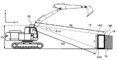
- the depth of the obstacle 14 is the end 14C of the obstacle 14. It can be calculated from 14D and 14E.
- the blind spot 16 is the angle between the distances XD and XE to the ends 14D and 14E of the obstacle 14.
- the upper end portion 14C of the obstacle 14 and the external environment recognition device Let ⁇ xza be the angle with the height Zs of 26, let ⁇ xzb be the angle between the lower end 14D of the obstacle 14 and the height Zs of the external environment recognition device 26, and in the range of the angle of ⁇ xzs, which is the sum of ⁇ xza and ⁇ xzb.
- the area behind the obstacle 14 is recognized as a blind spot 16.
- the bucket 10 of the own vehicle 13 may become a blind spot 16 depending on the installation location of the external environment recognition device 26. As shown in FIG. 9, depending on the posture of the hydraulic excavator 100, the bucket 10 blocks the field of view of the external environment recognition device 26 and forms a blind spot 16. In this case, if the external environment recognition device 26 can partially recognize the obstacle 14 through the bucket 10, it is not determined to be the blind spot 16.
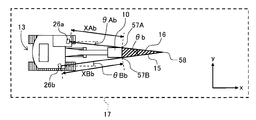
- the blind spot 16 when the external environment recognition device 26 is installed on the upper part of the cab 2, a blind spot 16 is formed also on the xy plane. Therefore, as shown in FIG. 11, for example, by installing the external environment recognition device 26 on the upper swing body 22 on the opposite side of the front working machine 24 when viewed from the cab 2 side, the range of the blind spot 16 can be narrowed. In this case, the blind spot 16 recognizes the point where both blind spot lines 15 of the external environment recognition devices 26a and 26b intersect, the range from the blind spot line intersection 58 to the angle ⁇ b as the blind spot up to the distance between the tip end portions 57A and 57B of the bucket. ..
- the angle ⁇ b is the sum of ⁇ Ab and ⁇ Bb.
- the distance xt (forward braking distance) from the time when the brake for stopping the movement in the forward direction is activated until the front working machine 24 stops is the forward speed v and the movement in the front-rear direction is stopped.
- the speed limiting region 40 has a radius of Rxt when the forward braking distance is xt, the length of the front working machine is R, and the sum value of the distance L0 from the turning center axis 25 to the swing center 38 is Rxt. Is the range obtained by turning ⁇ t. Further, the speed limit region 40 when the front work machine 24 is moving backward is a range in which the radius of the front work machine length R is turned by ⁇ t.
- the assumed movement range 41 of the moving body (worker) 39 is determined by the walking time of the moving body (worker) 39 and the distance r that the moving body (worker) 39 can move. For the walking time of the moving body (worker) 39, a value having a large time until the front working machine 24 brakes in the front-rear direction and the turning direction is selected.
- the distance r that the moving body (worker) 39 can move is such that the moving body (worker) 39 walks for the moving time when the walking speed of the moving body (worker) 39 is taken as the average walking speed of an adult. It is defined as a distance. Therefore, the assumed movement range 41 is a range in which the distance r that the worker can move is rotated by 360 ° from the surface of the moving body (worker) 39.
- the blind spot 16 is formed by the bucket 10
- the blind spot range can be complemented by using the information before forming the blind spot obtained by the external environment recognition device 26, and excessive control can be suppressed.
- the determination unit 31 determines whether or not the assumed movement range 41 calculated by the moving body course prediction unit 45 and the speed limit area 40 calculated by the operation range calculation unit 35 overlap, and the assumed movement range 41 and the operation range calculation unit 35 determine whether or not they overlap.
- the speed limit is transmitted to the work device 33 or the alarm device 59 is activated.
- the probability of contact with a moving body appearing from the blind spot 16 can be reduced.
- a margin is provided in the speed limiting area 40, the alarm device 59 is activated when the assumed movement range 41 overlaps within the margin, and the speed is moved to the working device 33 when the speed limiting area 40 and the assumed movement range 41 are likely to overlap. It is also possible to enforce restrictions.
- a main body including a lower traveling body and an upper rotating body provided so as to be rotatable with respect to the lower traveling body, and a plurality of bodies attached to the main body and rotatably connected.
- the front members are provided on the front members of the front working machine.
- a posture detection device that detects posture information, an external environment recognition device that detects objects around the main body, and a blind spot range that is a blind spot from the recognition range of the external environment recognition device by the object recognized by the external environment recognition device.
- the assumed movement range which is the range in which the moving body assumed to exist in the blind spot can move in a predetermined time
- the movable range which is the movable range in time
- preventive control is performed to prevent contact between the moving body and the front working machine based on the assumed moving range of the moving body and the movable range of the front working machine. Since it is configured to be provided with a control device, it is possible to sufficiently cope with a moving body in a blind spot of an object, and it is possible to more reliably prevent contact between the front working machine and the moving body.
- the blind spot 16 is calculated from the relative distance and the relative angle with the obstacle 14 by using the external environment recognition device 26, but in the present embodiment, for example, based on a GPS signal or the like.
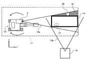
- a wireless communication device including a position measuring device 46 for measuring the position of the own vehicle 13 and a wireless communication device 47 for receiving information on the position of an obstacle 14 detected by the other vehicle 18, the position of the other vehicle 18, and the orientation of the main body. 47 transmits the information obtained from the other vehicle 18 to the blind spot calculation unit 37, and the blind spot calculation unit 37 sets the blind spot 16 and the moving body based on the information of the external environment recognition device 26, the position measuring device 46 and the wireless communication device 47. Is calculated for the position where is possible and the assumed movement range 41 of the moving body (worker) 39.
- FIG. 14 is a functional block diagram schematically showing a part of the processing functions of the control device mounted on the hydraulic excavator according to the present embodiment. Further, FIG. 15 is a diagram illustrating the calculation of the blind spot in the present embodiment. In the figure, the same members as those in the first embodiment are designated by the same reference numerals, and the description thereof will be omitted.
- the position measuring device 46 transmits the coordinate position of the own vehicle 13 to the blind spot calculation unit 37 based on, for example, a GPS signal.
- the wireless communication device 47 receives the information of the external environment recognition device 26 obtained by the other vehicle 18, the coordinate position of the other vehicle 18, and the orientation of the main body of the other vehicle 18 and transmits the information to the blind spot calculation unit 37.
- the blind spot calculation unit 37 calculates the blind spot 16 based on the information of the position measuring device 46, the wireless communication device 47, and the external environment recognition device 26 of the own vehicle 13, and transmits the blind spot 16 to the moving body course prediction unit 45.
- the other vehicle 18 when the other vehicle 18 is present at a position where the side of the obstacle 14 can be detected from inside and outside the working range 17, the other vehicle 18 has the coordinate position of the vehicle, the orientation of the main body, and the outside.
- the information of the environment recognition device 26 is transmitted via the wireless communication device 47.
- the own vehicle 13 receives the information obtained by the other vehicle 18 via the wireless communication device 47, and the blind spot calculation unit 37 calculates the positional relationship between the own vehicle 13 and the other vehicle 18 from the coordinate positions of the own vehicle 13 and the other vehicle 18. To do. Further, the position of the obstacle 14 and the blind spot 16 detected by the other vehicle 18 are calculated from the orientation of the main body of the other vehicle 18.
- the blind spot 16 of the obstacle 14 detected by the own vehicle 13 is represented by the range of the blind spot line 15a
- the blind spot 16 of the obstacle 14 detected by the other vehicle 18 is represented by the range of the blind spot line 15b.
- the blind spot calculation unit 37 compares the blind spot 16 calculated based on the information obtained by the own vehicle 13 with the blind spot 16 calculated based on the information of the other vehicle 18, and determines the range as the blind spot 16 by the own vehicle 13. If the other vehicle 18 can detect the above, the range is not recognized as the blind spot 16. As a result, it is not necessary to limit the speed for the work and the turning motion in the direction detected by the other vehicle 18.
- the technique of acquiring coordinate data such as LiDAR is used in the external environment recognition device 26 to obtain the relative distance and the relative angle to the obstacle 14, and further, the position of the own vehicle 13 is measured.
- the blind spot 16 was calculated from the position information of the other vehicle 18 obtained from the position measuring device 46 and the wireless communication device 47, the relative distance to the obstacle 14, and the relative angle.
- the own vehicle 13 A position estimation device for measuring a position, an image discrimination device 53 for photographing an object 14 using a camera or the like, a wireless communication device 47 for receiving information from another vehicle 18 via wireless communication, and an obstacle 14.
- the object determination unit 54 is equipped with an external environment recognition device 26 that transmits relative distance and relative angle to the obstacle determination unit 54, and an obstacle determination unit 54 that determines the obstacle 14 based on the information, and the obstacle is based on the information.
- the object determination unit 54 additionally implements a function of recognizing the obstacle 14 as another vehicle 18 and determining the vehicle type.
- FIG. 16 is a functional block diagram schematically showing a part of the processing functions of the control device mounted on the hydraulic excavator according to the present embodiment. Further, FIG. 17 is a diagram for explaining the calculation of the blind spot in the present embodiment, and FIG. 18 is a diagram for explaining the assumed transfer range of the moving body in the present embodiment. In the figure, the same members as those in the first and second embodiments are designated by the same reference numerals, and the description thereof will be omitted.
- the position measuring device 46 transmits the coordinates of the own vehicle 13 to the obstacle determination unit 54.
- the image discrimination device 53 photographs the obstacle 14 and transmits it to the obstacle discrimination unit 54.
- the wireless communication device 47 transmits the position information and the vehicle type information of the other vehicle 18 equipped with the position measuring device 46 to the obstacle determination unit 54.
- the obstacle discriminating unit 54 compares the image of the construction machine stored in advance with the image obtained from the image discriminating device 53, and discriminates whether or not the obstacle 14 is another vehicle 18. Further, the obstacle determination unit 54 calculates the positional relationship between the own vehicle 13 and the other vehicle 18 from the position of the own vehicle 13 obtained from the position measuring device 46 and the position information of the other vehicle 18 obtained from the wireless communication device 47. If the position of the obstacle 14 obtained from the external environment recognition device 26 matches the calculated position of the other vehicle 18, the obstacle 14 is recognized as the other vehicle 18.
- the type of the obstacle 14 can be discriminated by using the image discriminating device 53 and the obstacle discriminating unit 54, a certain distance behind is regarded as the obstacle 14 and the blind spot 16 is narrowed. be able to. As a result, the position where the moving body (worker) 39 may exist can be narrowed, and the probability that the assumed moving range 41 of the moving body (worker) 39 overlaps with the speed limiting area 40 can be reduced.
- the position of the moving body (worker) 39 existing in the blind spot 16 is the position closest to the own vehicle 13 in contact with the side surface 56 of the obstacle 14 and the blind spot line 15. Suppose it exists in. Further, when it is difficult to determine the obstacle 14, or when the obstacle 14 is not registered, the range of the blind spot is determined according to the blind spot detection method of the first embodiment.
- the present invention is not limited to the above-described embodiments, and various modifications and combinations are included within the scope of the invention. Further, the present invention is not limited to the one provided with all the configurations described in the above-described embodiments, and includes one obtained by deleting a part of the configuration. Further, the above-mentioned respective configurations, functions and the like may be realized by partially or entirely designing, for example, an integrated circuit. Further, each of the above configurations, functions, and the like may be realized by software by the processor interpreting and executing a program that realizes each function.
Landscapes
- Engineering & Computer Science (AREA)
- Mining & Mineral Resources (AREA)
- Civil Engineering (AREA)
- General Engineering & Computer Science (AREA)
- Structural Engineering (AREA)
- Mechanical Engineering (AREA)
- Computer Networks & Wireless Communication (AREA)
- Signal Processing (AREA)
- Human Computer Interaction (AREA)
- Operation Control Of Excavators (AREA)
- Component Parts Of Construction Machinery (AREA)
Abstract
フロント作業機のフロント部材に設けられ、フロント部材の姿勢情報を検出する姿勢検出装置と、本体の周囲の物体を検出する外環境認識装置と、外環境認識装置で認識された物体によって外環境認識装置の認識範囲から死角となる範囲である死角範囲を演算し、死角に存在すると仮定した移動体が予め定めた時間で移動可能な範囲である想定移動範囲を演算するとともに、姿勢検出装置で検出した姿勢情報に基づいてフロント作業機が予め定めた時間で移動可能な範囲である移動可能範囲を演算し、移動体の想定移動範囲とフロント作業機の移動可能範囲とに基づいて、移動体とフロント作業機との接触を予防する予防制御を行う制御装置とを備える。これにより、物体の死角の移動体にも十分に対応することができ、確実にフロント作業機と移動体との接触をより確実に予防することができる。
Description
本発明は、建設機械に関する。
建設土木施工業界における油圧ショベルなどの建設機械においては、作業を行うフロント作業機と作業員などとの接触を予防するものとして、例えば、特許文献1に記載のようにフロント作業機の作業速度を制御する技術がある。
特許文献1には、走行体(基体)に対して旋回可能に取り付けられたアタッチメントと、アタッチメントを旋回させる旋回機構と、旋回機構を制御する制御装置と、作業領域内へ進入した進入物の位置を検出する進入物検出装置とを有し、制御装置は、アタッチメントの現時点の角速度及びアタッチメントの現時点の慣性モーメントの少なくとも一方に関わる第1の物理量、及び進入物検出装置で検出された進入物の位置に基づいて、アタッチメントの旋回動作を制御する旋回作業機械が開示されている。
しかしながら、上記従来技術においては、検出した物体の死角に移動体が存在する可能性を考慮していないため、死角から移動体が出現した場合には十分に対応することができない。
本発明は上記に鑑みてなされたものであり、物体の死角の移動体にも対応することができ、確実にフロント作業機と移動体との接触をより確実に予防することができる建設機械を提供することを目的とする。
本願は上記課題を解決する手段を複数含んでいるが、その一例を挙げるならば、下部走行体と、前記下部走行体に対して旋回可能に設けられた上部旋回体とからなる本体と、前記上部旋回体に取り付けられ、回動可能に連結された複数のフロント部材からなる多関節型のフロント作業機と、前記フロント作業機の複数のフロント部材をそれぞれ駆動する複数のアクチュエータとを備えた建設機械において、前記フロント作業機のフロント部材に設けられ、前記フロント部材の姿勢情報を検出する姿勢検出装置と、前記本体の周囲の物体を検出する外環境認識装置と、前記外環境認識装置で認識された物体によって前記外環境認識装置の認識範囲から死角となる範囲である死角範囲を演算し、前記死角に存在すると仮定した移動体が予め定めた時間で移動可能な範囲である想定移動範囲を演算するとともに、前記姿勢検出装置で検出した姿勢情報に基づいて前記フロント作業機が予め定めた時間で移動可能な範囲である移動可能範囲を演算し、前記移動体の想定移動範囲と前記フロント作業機の移動可能範囲とに基づいて、前記移動体と前記フロント作業機との接触を予防する予防制御を行う制御装置とを備えたものとする。
本発明によれば、物体の死角の移動体にも十分に対応することができ、確実にフロント作業機と移動体との接触をより確実に予防することができる。
以下、本発明の実施の形態を図面を参照しつつ説明する。なお、本発明の実施の形態では、建設機械の一例として、フロント作業機を備える油圧ショベルを例示して説明するが、ホイールローダやクレーンのような作業機を備える他の建設機械にも本発明を適用することが可能である。
<第1の実施の形態>
本発明の第1の実施の形態を図1~図13を参照しつつ説明する。
本発明の第1の実施の形態を図1~図13を参照しつつ説明する。
図1は、本実施の形態に係る建設機械の一例である油圧ショベルの外観を模式的に示す図である。また、図2は、油圧ショベルの外観を模式的に示す側面図である。
図1及び図2において、油圧ショベル100は、油圧ショベル100は、垂直方向にそれぞれ回動する複数の被駆動部材(ブーム8、アーム9、バケット(作業具)10)を連結して構成された多関節型のフロント作業機24と、ショベル本体(以下、単に「本体」という)を構成する上部旋回体22及び下部走行体20とを備え、上部旋回体22は旋回機構21を介して下部走行体20に対して旋回可能に設けられている。旋回機構21は、旋回モータ23と旋回角度検出装置27とを有しており、旋回モータ23によって上部旋回体22が下部走行体20に対して旋回駆動され、旋回角度検出装置27によって下部走行体20に対する旋回角度が検出される。
フロント作業機24のブーム8の基端は上部旋回体22の前部に垂直方向に回動可能に支持されており、アーム9の一端はブーム8の基端とは異なる端部(先端)に垂直方向に回動可能に支持されており、アーム9の他端にはバケット10が垂直方向に回動可能に支持されている。ブーム8、アーム9、バケット10、上部旋回体22、及び下部走行体20は、油圧アクチュエータであるブームシリンダ5、アームシリンダ6、バケットシリンダ7、旋回モータ23、及び左右の走行モータ3(ただし、一方の走行モータのみを図示する)によりそれぞれ駆動される。
ここで、上部旋回体22の旋回中心軸25と上部旋回体22の下面との交点を原点とし、旋回中心軸25に沿って上方を正とするz軸を、原点からz軸に垂直となる前後方向に前方を正とするx軸を、原点からz軸およびx軸に垂直となる左右方向に右方向を正とするy軸を有する本体座標系を設定する。
上部旋回体22の前方左側には、オペレータが搭乗するキャブ2が搭載されている。また、上部旋回体22には、油圧ショベル100の全体の動作を制御する制御装置44が配置されている。キャブ2には、油圧アクチュエータ5~7,23を操作するための操作信号を出力する操作レバー(操作装置)2a,2bが設けられている。図示はしないが操作レバー2a,2bはそれぞれ前後左右に傾倒可能であり、操作信号であるレバーの傾倒量、すなわちレバー操作量を電気的に検知する図示しない検出装置を含み、検出装置が検出したレバー操作量を制御装置44(後述)に電気配線を介して出力する。つまり、操作レバー2a,2bの前後方向または左右方向に、油圧アクチュエータ5~7,23の操作がそれぞれ割り当てられている。
ブームシリンダ5、アームシリンダ6、バケットシリンダ7、旋回モータ23及び左右の走行モータ3の動作制御は、図示しないエンジンや電動モータなどの原動機によって駆動される油圧ポンプ装置から各油圧アクチュエータ3,5~7,23に供給される作動油の方向及び流量をコントロールバルブなどで制御することにより行う。コントロールバルブは、操作レバー2a,2bからの操作信号に基づいて制御装置44により動作制御され、これによって各油圧アクチュエータ5~7,23の動作が制御される。
ブーム8の基部、ブーム8とアーム9との接続部、及びアーム9とバケット10との接続部には、それぞれ、姿勢センサ34A,34B,34Cが取り付けられている。姿勢センサ34A,34B,34Cは、例えば、ポテンショメータのような機械式の角度センサである。図3に示すように、姿勢センサ34Aは、ブーム8の長手方向(両端の回動中心を結ぶ直線)とx-y平面とのなす角度β1を測定して制御装置44へ送信する。また、姿勢センサ34Bは、ブーム8の長手方向(両端の回動中心を結ぶ直線)とアーム9の長手方向(両端の回動中心を結ぶ直線)とのなす角度β2を測定して制御装置44へ送信する。また、姿勢センサ34Cは、アーム9の長手方向(両端の回動中心を結ぶ直線)とバケット10の長手方向(回動中心と爪先を結ぶ直線)とのなす角度β3を測定して制御装置44へ送信する。ここで、旋回角度検出装置27及び姿勢センサ34A~34Cは、上部旋回体22及びフロント作業機24の姿勢情報を検出する姿勢検出装置60を構成する。
なお、本実施の形態においては、フロント作業機24の揺動中心38(ブーム8の上部旋回体22との接続部)は、旋回中心軸25とは異なる位置に配置されている場合を例示して説明するが、旋回中心軸25と揺動中心38とが交差するように配置しても良い。
また、本実施の形態においては、姿勢検出装置60として角度センサなどを用いる場合を例示して説明したが、旋回角度検出装置27及び姿勢センサ34A~34Cとして、慣性計測装置(IMU: Inertial Measurement Unit)を用いても良い。また、ブームシリンダ5、アームシリンダ6、及びバケットシリンダ7にそれぞれストロークセンサを配置し、ストローク変化量から上部旋回体22やブーム8、アーム9、及びバケット10の各接続部分における相対的な向き(姿勢情報)を算出し、その結果から各角度を求めるように構成してもよい。
上部旋回体22には、ショベル本体(上部旋回体22、下部走行体20)の周囲の物体を検出する複数(例えば4つ)の外環境認識装置26が配置されている。外環境認識装置26の設置位置や数は特に本実施の形態の例に限定されるものではなく、本体の全方向(すなわち、油圧ショベル100の周囲360度)の視野を確保できれば良い。本実施の形態においては、4つの外環境認識装置26が、キャブ2の上部、上部旋回体22の左側方、右側方前部、及び、右側方後部にそれぞれ設置され、本体の周囲360度の視野を網羅している場合を例示して説明する。外環境認識装置26は、例えば、LiDAR(Laser Imaging Detection and Ranging、レーザー画像検出と測距)技術を用いたセンサであり、油圧ショベル100の周囲にある物体(例えば、後述する障害物14)を検出し、その座標データを制御装置44に送信する。
図3は、油圧ショベルに搭載される制御装置の処理機能の一部を模式的に示す機能ブロック図である。また、図4は、図3における機能の一部を詳細に示す機能ブロック図である。
図3及び図4において、制御装置44は、判定部31、動作範囲演算部35、死角演算部37、及び、移動体進路予測部45を備えている。また、動作範囲演算部35は、姿勢演算部43、旋回角度演算部48、速度制限領域演算部50、フロント作業機速度演算部51、及び、角速度演算部52を備えている。さらに、速度制限領域演算部50は、制動距離演算部30、及び、制動時間演算部49を備えている。
図3において、死角演算部37は、外環境認識装置26から得た上部旋回体22に対する相対的な位置関係から、死角を演算する。動作範囲演算部35は、姿勢検出装置60から得た情報をもとに制動時間を演算し、移動体進路予測部45へ制動時間を送信し、判定部31へ本体の動作範囲を送信する。動作範囲演算部35で行う演算は後に詳述する。移動体進路予測部45は、得られた死角16の位置、および形状から作業員などの移動体が潜んでいる可能性があるか否かを判断し、また、得られたフロント作業機24の制動時間から、フロント作業機24が制動するまでの間に移動体が移動し得る範囲、想定移動範囲41を演算し、判定部31へ送信する。判定部31は、移動体進路予測部45と動作範囲演算部35で得られた情報をもとに作業装置33の速度を制限する、もしくは警報装置59を作動させるか否かを判定する。判定部31の演算についての詳細は後述する。
図4において、姿勢演算部43は、姿勢センサ34で得られるブーム8、アーム9、バケット10それぞれの角度情報をもとにフロント作業機24の長さを演算し、速度制限領域演算部50へ送信する。また、フロント作業機速度演算部51では、姿勢センサ34で得られるブーム8、アーム9、バケット10それぞれの角度の変動をもとにフロント作業機24が移動する速度(フロント作業機速度)を演算し、速度制限領域演算部50へ送信する。また、旋回角度演算部48では、下部走行体20の前方向を0°とし、上部旋回体22の左旋回方向を正として自車両13の旋回角度を演算し、速度制限領域演算部50へ送信する。また、角速度演算部52は、旋回角度検出装置27から入力された旋回角の変化速度に基づいて、フロント作業機24の角速度を演算し、速度制限領域演算部50へ送信する。速度制限領域演算部50は制動距離演算部30と制動時間演算部49から成る。制動距離演算部30は、姿勢演算部43で得られたフロント作業機長とフロント作業機速度演算部51より得られたフロント作業機24の移動速度と、旋回角度演算部48より得られた旋回角度と、角速度演算部52より得られた角速度から、フロント作業機24の制動距離を演算し、判定部31へ送信する。また、制動時間演算部49は、姿勢演算部43で得られたフロント作業機長とフロント作業機速度演算部51より得られたフロント作業機24の移動速度と、旋回角度演算部48より得られた旋回角度と、角速度演算部52より得られた角速度から、フロント作業機24の制動時間を演算し、移動体進路予測部45へ送信する。
以上のように構成した制御装置44は、外環境認識装置26で認識された物体によって外環境認識装置の認識範囲から死角となる範囲である死角範囲(死角16)を演算し、死角に存在すると仮定した移動体39が予め定めた時間で移動可能な範囲である想定移動範囲41を演算するとともに、姿勢検出装置60で検出した姿勢情報に基づいてフロント作業機24が予め定めた時間で移動可能な範囲である移動可能範囲を演算し、移動体39の想定移動範囲41とフロント作業機24の移動可能範囲とに基づいて、移動体39とフロント作業機24との接触を予防する予防制御を行う。
図13は、予防制御の処理内容を示すフローチャートである。
図13において、制御装置44は、まず、障害物があるかどうかを判定し(ステップS101)、判定結果がYESの場合には、油圧ショベル本体の姿勢を検出し(ステップS102)、障害物により生じる死角を演算する死角範囲演算を行う(ステップS103)。
続いて、移動体が死角に潜む可能性があるかどうかを判定し(ステップS104)、判定結果がYESの場合には、フロント作業機24の制動時間を演算する制動時間演算を行い(ステップS105)、フロント作業機24の移動範囲を演算する動作範囲演算処理を行い(ステップS106)、移動体の相対移動範囲を演算する想定移動範囲演算を行う(ステップS107)。
続いて、移動体とフロント作業機24とが接触する可能性があるかどうかを判定し(ステップS108)、判定結果がYESの場合には、フロント作業機24の駆動に係る制限速度を決定し(ステップS109)、警報装置59の作動や作業速度の制御作動を行う(ステップS110)。
続いて、本体は停止したかどうかを判定し(ステップS111)、判定結果がNOの場合には、判定結果がYESになるまで、ステップS110の処理を繰り返す。また、ステップS111での判定結果がYESの場合には、処理を終了する。
また、ステップS101,S104,S108の何れかの判定結果がNOの場合には、処理を終了する。
以上のような予防制御についてさらに詳細に説明する。
まず、図2に示したフロント作業機長Rとバケット高さZbの算出方法について説明する。フロント作業機長Rは、旋回中心軸25からフロント作業機24の先端までの距離Rである。ブーム8、アーム9、及びバケット10の長さを、それぞれL1,L2,L3とする。x-y面と、ブーム8の長手方向とのなす角度β1が、姿勢センサ34Aにより測定される。ブーム8とアーム9とのなす角度β2、及びアーム9とバケット10とのなす角度β3が、それぞれ姿勢センサ34B、34Cにより測定される。x-y面から揺動中心38までの高さZ0は、予め求められている。また、旋回中心軸25から揺動中心38までの距離L0も予め求められている。
角度β1及び角度β2から、xy面とアーム9の長手方向とのなす角度β2aを計算することができる。角度β1、角度β2、β3から、xy面とバケット10の長手方向とのなす角度β3bを計算することができる。バケット高さZb、及びフロント作業機長Rは、以下の(式1)及び(式2)により計算することができる。
Zb=Z0+L1sinβ1+L2sinβ2+L3sinβ3 ・・・(式1)
R=L0+L1cosβ1+ L2cosβ2+L3cosβ3 ・・・(式2)
Zb=Z0+L1sinβ1+L2sinβ2+L3sinβ3 ・・・(式1)
R=L0+L1cosβ1+ L2cosβ2+L3cosβ3 ・・・(式2)
次に、図5~図11を用いて本発明による第1の実施例の制御装置44で行われる死角16の演算手法について説明する。まず、図5を用いてxy平面での死角算出方法について説明する。外環境認識装置26で得られた障害物14の座標をもとに、制御装置44内の障害物位置演算部36にてxy平面での自車両13と、障害物14の左右両端部14Aおよび14Bそれぞれの相対角度θxya、θxybと相対距離XA、XBを演算する。これらの情報をもとに、死角演算部37で障害物14により死角16が存在するか否かを演算する。この場合、死角16は斜線で示した範囲をさし、検出した障害物14の表面側を前方とした場合、障害物14を検出した位置より後方の領域を死角16として認識する。すなわち、外環境認識装置26から障害物14の両端部14A、14Bまでの距離をそれぞれXA、XBとした場合、外環境認識装置26から障害物14の端部までの距離XAとXBの角度θxyの範囲よりも後方を死角16として認識する。なお、死角16の大きさが、一般的な移動体(作業員)39よりも小さい場合、死角16がないものとしてもよい。こうすることにより、過剰な制御介入を避けることができる。
次に、図6~図8を用いて、xz平面での死角検出方法について説明する。
図6に示すように、検出した障害物14の高さZが外環境認識装置26が設置されている高さZsと同じ場合においては、死角16高さは高さZと規定される。外環境認識装置26から障害物14の上下端部14C、14Dまでの距離XCとXDの角度θxzの範囲より後方を死角16として認識する。
一方、図7に示したように、外環境認識装置26が設置されている高さZsより障害物14の高さZが低い場合は、障害物14の奥行きは障害物14の端部14C、14D、14Eより計算することができる。ここで、障害物14の両端は14Dと14Eとなるため、死角16は障害物14の端部14Dと14Eまでの距離XDとXEの角度となる。外環境認識装置26を障害物14より高い位置に配置することで、障害物14の奥行きを検出することが可能となるため、なるべく高い位置に外環境認識装置26を設置することが望ましい。また、高い位置に外環境認識装置26を設置することが困難な場合においても、検出した高さZの高さが移動体(作業員)39が潜むことができる高さでない場合は、制御を実施しなくてもよい。
また、図8に示した通り、検出した障害物14の高さZが外環境認識装置26が設置されている高さZsよりも高い場合は、障害物14の上端部14Cと外環境認識装置26の高さZsとの角度をθxzaとし、障害物14の下端部14Dと外環境認識装置26の高さZsとの角度をθxzbとし、θxzaとθxzbの和であるθxzsの角度の範囲において、障害物14より後方の領域を死角16として認識する。
次に、図9~図11を用いて自車両13のバケット10が死角16になる場合について説明する。
図9に示したように、外環境認識装置26の設置場所によっては、自車両13のバケット10が死角16になる場合がある。図9に示したように、油圧ショベル100の姿勢によってはバケット10が外環境認識装置26の視野を遮り、死角16を形成する。この場合、外環境認識装置26がバケット10越しに部分的に障害物14を認識できる場合は死角16と判断しない。
また、図10に示したように、外環境認識装置26をキャブ2の上部に設置した場合、xy平面においても死角16を形成する。そのため、図11に示す通り、例えば外環境認識装置26をキャブ2側からみてフロント作業機24の反対側の上部旋回体22に設置することで、死角16の範囲を狭めることができる。この場合、死角16は、外環境認識装置26aと26bの両死角線15が交差する点、死角線交差点58から角度θbの範囲をバケットの先端端部57Aと57Bの距離までを死角として認識する。ここで、角度θbはθAbとθBbの和である。
次に、図12を用いて速度制限領域40、移動体(作業員)39が存在し得る位置、想定移動範囲41の演算手法、バケット10による死角の対処法および作業装置33の制御方法について説明する。
図12に示すように、現時点のフロント作業機24の角速度がωであり、フロント作業機長がRであるとする。その場合、旋回を停止させるためのブレーキを作動させた時点から、フロント作業機24が停止するまでに旋回する角度θt(制動角度)は、最大制動力をかけた場合に制動までかかる時間をtθ(旋回制動時間)、旋回加速度をα、初期角度をθt0とした場合、以下の(式3)により計算することができる。
θt=θt0+ω×tθ+(α×tθ^2)/2 ・・・(式3)
θt=θt0+ω×tθ+(α×tθ^2)/2 ・・・(式3)
また、前進方向の移動を停止させるためのブレーキを作動させた時点から、フロント作業機24が停止するまでに前進する距離xt(前進制動距離)は、前進速度vと前後方向の移動を停止させるためのブレーキを作動させた時点から、フロント作業機24が停止するまでにかかる時間(前後進制動時間)をtx、減速加速度をaとした場合、以下の(式4)により計算することができる。
xt=v×tx+(a×tx^2)/2 ・・・(式4)
xt=v×tx+(a×tx^2)/2 ・・・(式4)
そのため、速度制限領域40は、前進制動距離をxt、フロント作業機の長さをR、旋回中心軸25から揺動中心38までの距離L0の和の値をRxtとした場合、このRxtの半径をθt旋回させた範囲とする。また、フロント作業機24が後進している場合における速度制限領域40は、フロント作業機長Rの半径をθt旋回させた範囲とする。
次に、移動体(作業員)39の想定移動範囲41の演算方法について説明する。死角16内に存在する移動体(作業員)39は、障害物14の両端部14Aと14Bを結んだ表面線42と死角線15の両線に接する位置に存在すると仮定する。その場合、移動体(作業員)39の想定移動範囲41は、移動体(作業員)39の歩行時間と移動体(作業員)39が移動し得る距離rによって決まる。移動体(作業員)39の歩行時間はフロント作業機24が前後方向および旋回方向に制動するまでの時間の大きい値を選択する。また、移動体(作業員)39が移動し得る距離rは、移動体(作業員)39の歩行速度を大人の平均歩行速度とした場合、移動体(作業員)39が移動時間分歩行した距離と規定される。そのため、想定移動範囲41は作業員が移動し得る距離rを移動体(作業員)39の表面から360°回転させた範囲である。
また、バケット10による死角の対処法について説明する。仮にバケット10によって死角16が形成された場合は、外環境認識装置26で得た死角を形成する前の情報を用いて死角範囲を補完し、過剰に制御をかけることを抑制することができる。
判定部31は移動体進路予測部45で演算した想定移動範囲41と動作範囲演算部35で演算した速度制限領域40が重なるか否かを判定し、想定移動範囲41と動作範囲演算部35で演算した速度制限領域40が重なりそうな場合において作業装置33へ速度制限を送信、もしくは警報装置59を作動させる。このような判定部31を設けることによって死角16から出現する移動体との接触確率を低減することができる。さらに、速度制限領域40にマージンをもたせ、マージン内に想定移動範囲41が重なった場合に警報装置59を作動させ、速度制限領域40と想定移動範囲41が重なりそうな場合において作業装置33へ速度制限を実施することも可能である。
以上のように構成した本実施の形態の効果を説明する。
建設土木施工業界における油圧ショベルなどの建設機械においては、作業を行うフロント作業機と作業員などとの接触を予防するものとして、フロント作業機の作業速度を制御する従来技術があった。しかしながら、従来技術においては、検出した物体の死角に移動体が存在する可能性を考慮していないため、死角から移動体が出現した場合には十分に対応することができなかった。
これに対して本実施の形態においては、下部走行体と、下部走行体に対して旋回可能に設けられた上部旋回体とからなる本体と、本体に取り付けられ、回動可能に連結された複数のフロント部材からなる多関節型のフロント作業機と、フロント作業機の複数のフロント部材をそれぞれ駆動する複数のアクチュエータとを備えた建設機械において、フロント作業機のフロント部材に設けられ、フロント部材の姿勢情報を検出する姿勢検出装置と、本体の周囲の物体を検出する外環境認識装置と、外環境認識装置で認識された物体によって外環境認識装置の認識範囲から死角となる範囲である死角範囲を演算し、死角に存在すると仮定した移動体が予め定めた時間で移動可能な範囲である想定移動範囲を演算するとともに、姿勢検出装置で検出した姿勢情報に基づいてフロント作業機が予め定めた時間で移動可能な範囲である移動可能範囲を演算し、移動体の想定移動範囲とフロント作業機の移動可能範囲とに基づいて、移動体とフロント作業機との接触を予防する予防制御を行う制御装置とを備えて構成したので、物体の死角の移動体にも十分に対応することができ、確実にフロント作業機と移動体との接触をより確実に予防することができる。
<第2の実施の形態>
本発明の第2の実施の形態を図14及び図15を参照しつつ説明する。
本発明の第2の実施の形態を図14及び図15を参照しつつ説明する。
第1の実施の形態では、外環境認識装置26を用いて障害物14との相対距離および相対角度から死角16を演算していたが、本実施の形態は、例えばGPS信号などをもとに自車両13の位置を測定する位置測定装置46と、他車両18で検出した障害物14の位置、他車両18の位置、本体の向きの情報を受信する無線通信装置47を備え、無線通信装置47は他車両18から得られた情報を死角演算部37に送信し、死角演算部37は外環境認識装置26、位置測定装置46と無線通信装置47の情報をもとに死角16、移動体が存在し得る位置、移動体(作業員)39の想定移動範囲41を演算するものである。
図14は、本実施の形態における油圧ショベルに搭載される制御装置の処理機能の一部を模式的に示す機能ブロック図である。また、図15は、本実施の形態における死角の演算について説明する図である。図中、第1の実施の形態と同様の部材には同じ符号を付し、説明を省略する。
図14に示すように、位置測定装置46では、例えばGPS信号などをもとに自車両13の座標位置を死角演算部37へ送信する。また、無線通信装置47は他車両18が得た外環境認識装置26の情報と、他車両18の座標位置と、他車両18の本体の向きを受信し、死角演算部37に送信する。死角演算部37は位置測定装置46、無線通信装置47、自車両13の外環境認識装置26の情報をもとに、死角16を演算し、移動体進路予測部45へ送信する。
図15に示す通り、例えば、他車両18が作業範囲17内外から障害物14の側方を検出することができる位置に存在する場合、他車両18は車両の座標位置と本体の向き、および外環境認識装置26の情報を無線通信装置47を介して送信する。自車両13は他車両18で得た情報を無線通信装置47を介して受信し、死角演算部37にて、自車両13と他車両18の座標位置から、自車両13との位置関係を演算する。また、他車両18の本体の向きから、他車両18が検知している障害物14の位置と死角16を演算する。ここで、自車両13で検出した障害物14の死角16は死角線15aの範囲で表され、他車両18で検出した障害物14の死角16は死角線15bの範囲で表される。
さらに、死角演算部37は自車両13で得た情報をもとに演算した死角16と他車両18の情報をもとに演算した死角16を比較し、自車両13で死角16として判断した範囲を他車両18が検出できていれば、その範囲を死角16として認識しない。その結果、他車両18が検出している方面への作業および旋回動作については速度制限を実施する必要がなくなる。
その他の構成については第1の実施の形態と同様である。
以上のように構成した本実施の形態においても第1の実施の形態と同様の効果を得ることができる。
<第3の実施の形態>
本発明の第3の実施の形態を図16~図18を参照しつつ説明する。
本発明の第3の実施の形態を図16~図18を参照しつつ説明する。
第2の実施の形態では、外環境認識装置26においてLiDAR等の座標データを取得する技術を使用し、障害物14との相対距離と相対角度を求め、さらに、自車両13の位置を測定する位置測定装置46と、無線通信装置47から得られる他車両18の位置情報や障害物14までの相対距離と相対角度から死角16を演算していたが、本実施の形態は、自車両13の位置を測定する位置推定装置と、カメラ等を用いて対象物14を撮影する画像判別装置53と、無線通信を介して他車両18より情報を受信する無線通信装置47と、障害物14との相対距離と相対角度を障害物判別部54へ送信する外環境認識装置26と、それらの情報をもとに障害物14を判別する障害物判別部54をそなえ、それらの情報をもとに障害物判別部54は障害物14を他車両18と認識し、車種を判断する機能を追加実装したものである。
図16は、本実施の形態における油圧ショベルに搭載される制御装置の処理機能の一部を模式的に示す機能ブロック図である。また、図17は本実施の形態における死角の演算について説明する図であり、図18は本実施の形態における移動体の想定異動範囲について説明する図である。図中、第1及び第2の実施の形態と同様の部材には同じ符号を付し、説明を省略する。
図16に示した通り、位置測定装置46は自車両13の座標を障害物判別部54へ送信する。また、画像判別装置53は障害物14を撮影し、障害物判別部54へ送信する。無線通信装置47は位置測定装置46を搭載した他車両18の位置情報と車種情報を障害物判別部54へ送信する。障害物判別部54では、あらかじめ記憶した建設機械の画像と画像判別装置53から得られた画像を照らし合わせ、障害物14が他車両18か否かを判別する。また、障害物判別部54では、位置測定装置46から得られる自車両13の位置と、無線通信装置47から得られる他車両18の位置情報から自車両13と他車両18の位置関係を演算し、外環境認識装置26から得られた障害物14の位置が演算した他車両18の位置と一致する場合は、障害物14を他車両18として認識する。
図17に示すように、画像判別装置53と障害物判別部54を用いることで、障害物14の種類を判別することができるため、後方の一定距離を障害物14とみなし、死角16を狭めることができる。その結果移動体(作業員)39が存在する可能性がある位置を狭めることができ、移動体(作業員)39の想定移動範囲41が速度制限領域40と重なる確率を低減することができる。
ここで、死角16内に存在する移動体(作業員)39の位置は、図18に示すように、障害物14の側面56と死角線15に接する、最も自車両13に接近している位置に存在すると仮定する。また、障害物14を判別することが困難な場合や登録されていない障害物14については、実施例1の死角検知手法にのっとり、死角の範囲を判断する。
その他の構成は第1及び第2の実施の形態と同様である。
以上のように構成した本実施の形態においても第1及び第2の実施の形態と同様の効果を得ることができる。
<付記>
なお、本発明は上記の実施の形態に限定されるものではなく、その要旨を逸脱しない範囲内の様々な変形例や組み合わせが含まれる。また、本発明は、上記の実施の形態で説明した全ての構成を備えるものに限定されず、その構成の一部を削除したものも含まれる。また、上記の各構成、機能等は、それらの一部又は全部を、例えば集積回路で設計する等により実現してもよい。また、上記の各構成、機能等は、プロセッサがそれぞれの機能を実現するプログラムを解釈し、実行することによりソフトウェアで実現してもよい。
なお、本発明は上記の実施の形態に限定されるものではなく、その要旨を逸脱しない範囲内の様々な変形例や組み合わせが含まれる。また、本発明は、上記の実施の形態で説明した全ての構成を備えるものに限定されず、その構成の一部を削除したものも含まれる。また、上記の各構成、機能等は、それらの一部又は全部を、例えば集積回路で設計する等により実現してもよい。また、上記の各構成、機能等は、プロセッサがそれぞれの機能を実現するプログラムを解釈し、実行することによりソフトウェアで実現してもよい。
2…キャブ、2a,2b…操作レバー(操作装置)、3…走行モータ、5…ブームシリンダ、6…アームシリンダ、7…バケットシリンダ、8…ブーム、9…アーム、10…バケット、13…自車両、14…障害物(対象物)、15…死角線、15…両死角線、16…死角、17…作業範囲、18…他車両、20…下部走行体、21…旋回機構、22…上部旋回体、23…旋回モータ、24…フロント作業機、25…旋回中心軸、26…外環境認識装置、27…旋回角度検出装置、30…制動距離演算部、31…判定部、34…姿勢センサ、35…動作範囲演算部、36…障害物位置演算部、37…死角演算部、38…揺動中心、39…移動体(作業員)、40…速度制限領域、41…想定移動範囲、42…表面線、43…姿勢演算部、44…制御装置、45…移動体進路予測部、46…位置測定装置、47…無線通信装置、48…旋回角度演算部、49…制動時間演算部、50…速度制限領域演算部、51…フロント作業機速度演算部、52…角速度演算部、53…画像判別装置、54…障害物判別部、59…警報装置、60…姿勢検出装置、100…油圧ショベル
Claims (5)
- 下部走行体と、前記下部走行体に対して旋回可能に設けられた上部旋回体とからなる本体と、
前記上部旋回体に取り付けられ、回動可能に連結された複数のフロント部材からなる多関節型のフロント作業機と、
前記フロント作業機の複数のフロント部材をそれぞれ駆動する複数のアクチュエータとを備えた建設機械において、
前記フロント作業機のフロント部材に設けられ、前記フロント部材の姿勢情報を検出する姿勢検出装置と、
前記本体の周囲の物体を検出する外環境認識装置と、
前記外環境認識装置で認識された物体によって前記外環境認識装置の認識範囲から死角となる範囲である死角範囲を演算し、前記死角に存在すると仮定した移動体が予め定めた時間で移動可能な範囲である想定移動範囲を演算するとともに、前記姿勢検出装置で検出した姿勢情報に基づいて前記フロント作業機が予め定めた時間で移動可能な範囲である移動可能範囲を演算し、前記移動体の想定移動範囲と前記フロント作業機の移動可能範囲とに基づいて、前記移動体と前記フロント作業機との接触を予防する予防制御を行う制御装置と
を備えたことを特徴とする建設機械。 - 請求項1記載の建設機械において、
前記制御装置は、前記予防制御として、前記フロント作業機の移動可能範囲と前記移動体の想定移動範囲とが重複しないように、前記フロント作業機のアクチュエータを制御することを特徴とする建設機械。 - 請求項1記載の建設機械において、
前記制御装置は、前記フロント作業機の移動可能範囲と前記移動体の想定移動範囲とが予め定めた距離よりも近づいた場合に、警報装置によってオペレータにそのことを報知することを特徴とする建設機械。 - 請求項1記載の建設機械において、
作業現場における前記建設機械の位置を計測する位置測定装置と、
前記作業現場における他の建設機械で得られた前記他の建設機械の位置、及び、前記他の建設機械に設けられた外環境認識装置の検出結果を取得する無線通信装置とを備え、
前記制御装置は、前記外環境認識装置の死角範囲と前記他の建設機械の外環境認識装置の検出結果とが重複する場合には、前記死角範囲の少なくとも一部を前記他の建設機械の外環境認識装置の検出結果に置き換えることを特徴とする建設機械。 - 請求項1記載の建設機械において、
前記制御装置は、前記外環境認識装置で検出された物体の種類を判別し、判別した物体の種類に応じて前記死角範囲を演算することを特徴とする建設機械。
Priority Applications (4)
| Application Number | Priority Date | Filing Date | Title |
|---|---|---|---|
| KR1020217027634A KR102579791B1 (ko) | 2019-03-14 | 2020-02-14 | 건설 기계 |
| CN202080017560.1A CN113508206B (zh) | 2019-03-14 | 2020-02-14 | 工程机械 |
| US17/422,643 US20210388578A1 (en) | 2019-03-14 | 2020-02-14 | Construction machine |
| EP20770062.6A EP3904609B1 (en) | 2019-03-14 | 2020-02-14 | Construction machine |
Applications Claiming Priority (2)
| Application Number | Priority Date | Filing Date | Title |
|---|---|---|---|
| JP2019-047081 | 2019-03-14 | ||
| JP2019047081A JP7111641B2 (ja) | 2019-03-14 | 2019-03-14 | 建設機械 |
Publications (1)
| Publication Number | Publication Date |
|---|---|
| WO2020184065A1 true WO2020184065A1 (ja) | 2020-09-17 |
Family
ID=72426792
Family Applications (1)
| Application Number | Title | Priority Date | Filing Date |
|---|---|---|---|
| PCT/JP2020/005800 WO2020184065A1 (ja) | 2019-03-14 | 2020-02-14 | 建設機械 |
Country Status (6)
| Country | Link |
|---|---|
| US (1) | US20210388578A1 (ja) |
| EP (1) | EP3904609B1 (ja) |
| JP (1) | JP7111641B2 (ja) |
| KR (1) | KR102579791B1 (ja) |
| CN (1) | CN113508206B (ja) |
| WO (1) | WO2020184065A1 (ja) |
Cited By (1)
| Publication number | Priority date | Publication date | Assignee | Title |
|---|---|---|---|---|
| EP4224452A4 (en) * | 2020-09-29 | 2024-03-06 | Sony Semiconductor Solutions Corp | INFORMATION PROCESSING SYSTEM AND INFORMATION PROCESSING METHOD |
Families Citing this family (1)
| Publication number | Priority date | Publication date | Assignee | Title |
|---|---|---|---|---|
| US11898331B2 (en) * | 2020-12-02 | 2024-02-13 | Caterpillar Sarl | System and method for detecting objects within a working area |
Citations (7)
| Publication number | Priority date | Publication date | Assignee | Title |
|---|---|---|---|---|
| JP2011028729A (ja) * | 2009-07-03 | 2011-02-10 | Takenaka Komuten Co Ltd | 接触防止システム、建設機械およびプログラム |
| JP2012021290A (ja) | 2010-07-13 | 2012-02-02 | Sumitomo Heavy Ind Ltd | 旋回作業機械及び旋回作業機械の制御方法 |
| JP2016024685A (ja) * | 2014-07-22 | 2016-02-08 | 日立建機株式会社 | 鉱山用作業車両 |
| WO2018008542A1 (ja) * | 2016-07-05 | 2018-01-11 | 住友建機株式会社 | ショベル |
| JP2018093501A (ja) * | 2018-01-04 | 2018-06-14 | 住友重機械工業株式会社 | 作業機械 |
| JP2018172943A (ja) * | 2017-03-31 | 2018-11-08 | コベルコ建機株式会社 | 干渉監視装置 |
| WO2019039593A1 (ja) * | 2017-08-24 | 2019-02-28 | 日立建機株式会社 | 作業機械 |
Family Cites Families (10)
| Publication number | Priority date | Publication date | Assignee | Title |
|---|---|---|---|---|
| JP2753778B2 (ja) * | 1991-10-24 | 1998-05-20 | 株式会社フジタ | 建設作業車の自動制御装置 |
| JP4108412B2 (ja) * | 2002-08-19 | 2008-06-25 | 株式会社小松製作所 | 作業車両 |
| EP2615596A4 (en) * | 2010-09-08 | 2017-12-06 | Toyota Jidosha Kabushiki Kaisha | Moving-object prediction device, virtual-mobile-object prediction device, program, mobile-object prediction method, and virtual-mobile-object prediction method |
| JP5573617B2 (ja) * | 2010-11-12 | 2014-08-20 | トヨタ自動車株式会社 | 危険度算出装置 |
| US9975485B2 (en) * | 2014-04-25 | 2018-05-22 | Komatsu Ltd. | Surroundings monitoring system, work vehicle, and surroundings monitoring method |
| CN106575474A (zh) * | 2014-07-28 | 2017-04-19 | 三菱电机株式会社 | 行驶辅助系统及行驶辅助方法 |
| JP2016122308A (ja) * | 2014-12-25 | 2016-07-07 | クラリオン株式会社 | 車両制御装置 |
| JP6581139B2 (ja) * | 2017-03-31 | 2019-09-25 | 日立建機株式会社 | 作業機械の周囲監視装置 |
| JP7163729B2 (ja) * | 2018-11-08 | 2022-11-01 | トヨタ自動車株式会社 | 車両制御装置 |
| JP7180436B2 (ja) * | 2019-02-15 | 2022-11-30 | 株式会社デンソー | 行動制御方法、及び行動制御装置 |
-
2019
- 2019-03-14 JP JP2019047081A patent/JP7111641B2/ja active Active
-
2020
- 2020-02-14 WO PCT/JP2020/005800 patent/WO2020184065A1/ja unknown
- 2020-02-14 EP EP20770062.6A patent/EP3904609B1/en active Active
- 2020-02-14 US US17/422,643 patent/US20210388578A1/en active Pending
- 2020-02-14 KR KR1020217027634A patent/KR102579791B1/ko active IP Right Grant
- 2020-02-14 CN CN202080017560.1A patent/CN113508206B/zh active Active
Patent Citations (7)
| Publication number | Priority date | Publication date | Assignee | Title |
|---|---|---|---|---|
| JP2011028729A (ja) * | 2009-07-03 | 2011-02-10 | Takenaka Komuten Co Ltd | 接触防止システム、建設機械およびプログラム |
| JP2012021290A (ja) | 2010-07-13 | 2012-02-02 | Sumitomo Heavy Ind Ltd | 旋回作業機械及び旋回作業機械の制御方法 |
| JP2016024685A (ja) * | 2014-07-22 | 2016-02-08 | 日立建機株式会社 | 鉱山用作業車両 |
| WO2018008542A1 (ja) * | 2016-07-05 | 2018-01-11 | 住友建機株式会社 | ショベル |
| JP2018172943A (ja) * | 2017-03-31 | 2018-11-08 | コベルコ建機株式会社 | 干渉監視装置 |
| WO2019039593A1 (ja) * | 2017-08-24 | 2019-02-28 | 日立建機株式会社 | 作業機械 |
| JP2018093501A (ja) * | 2018-01-04 | 2018-06-14 | 住友重機械工業株式会社 | 作業機械 |
Cited By (1)
| Publication number | Priority date | Publication date | Assignee | Title |
|---|---|---|---|---|
| EP4224452A4 (en) * | 2020-09-29 | 2024-03-06 | Sony Semiconductor Solutions Corp | INFORMATION PROCESSING SYSTEM AND INFORMATION PROCESSING METHOD |
Also Published As
| Publication number | Publication date |
|---|---|
| EP3904609A4 (en) | 2022-11-09 |
| KR20210120085A (ko) | 2021-10-06 |
| CN113508206B (zh) | 2023-01-10 |
| EP3904609A1 (en) | 2021-11-03 |
| EP3904609B1 (en) | 2024-01-17 |
| US20210388578A1 (en) | 2021-12-16 |
| JP2020148029A (ja) | 2020-09-17 |
| JP7111641B2 (ja) | 2022-08-02 |
| KR102579791B1 (ko) | 2023-09-19 |
| CN113508206A (zh) | 2021-10-15 |
Similar Documents
| Publication | Publication Date | Title |
|---|---|---|
| EP3409843B1 (en) | Working machine | |
| JP7358349B2 (ja) | 掘削機、情報処理装置 | |
| CN112513378B (zh) | 作业机械 | |
| JP7114248B2 (ja) | 建設機械 | |
| WO2020170687A1 (ja) | 安全装置及び建設機械 | |
| WO2019189031A1 (ja) | ショベル | |
| WO2020184065A1 (ja) | 建設機械 | |
| WO2020166241A1 (ja) | 監視装置及び建設機械 | |
| WO2021192655A1 (ja) | 作業機械 | |
| CN114867922B (zh) | 作业机械以及控制系统 | |
| JP7222775B2 (ja) | 作業機械 | |
| WO2020255970A1 (ja) | 作業機械 | |
| WO2021029253A1 (ja) | 作業機械 | |
| JP7491787B2 (ja) | 作業機械の制御システムおよび作業機械の制御方法 | |
| WO2022030286A1 (ja) | 作業機械の制御システム | |
| WO2021066057A1 (ja) | 侵入監視制御システムおよび作業機械 | |
| JP2023145210A (ja) | 作業機械 | |
| JP2024030384A (ja) | 作業機械の安全装置 | |
| JP2021050583A (ja) | 作業機械 |
Legal Events
| Date | Code | Title | Description |
|---|---|---|---|
| 121 | Ep: the epo has been informed by wipo that ep was designated in this application |
Ref document number: 20770062 Country of ref document: EP Kind code of ref document: A1 |
|
| ENP | Entry into the national phase |
Ref document number: 2020770062 Country of ref document: EP Effective date: 20210727 |
|
| ENP | Entry into the national phase |
Ref document number: 20217027634 Country of ref document: KR Kind code of ref document: A |
|
| NENP | Non-entry into the national phase |
Ref country code: DE |