WO2020184044A1 - 純水製造装置および純水の製造方法 - Google Patents
純水製造装置および純水の製造方法 Download PDFInfo
- Publication number
- WO2020184044A1 WO2020184044A1 PCT/JP2020/005550 JP2020005550W WO2020184044A1 WO 2020184044 A1 WO2020184044 A1 WO 2020184044A1 JP 2020005550 W JP2020005550 W JP 2020005550W WO 2020184044 A1 WO2020184044 A1 WO 2020184044A1
- Authority
- WO
- WIPO (PCT)
- Prior art keywords
- water
- reverse osmosis
- osmosis membrane
- membrane device
- treated
- Prior art date
- Legal status (The legal status is an assumption and is not a legal conclusion. Google has not performed a legal analysis and makes no representation as to the accuracy of the status listed.)
- Ceased
Links
Images



Classifications
-
- C—CHEMISTRY; METALLURGY
- C02—TREATMENT OF WATER, WASTE WATER, SEWAGE, OR SLUDGE
- C02F—TREATMENT OF WATER, WASTE WATER, SEWAGE, OR SLUDGE
- C02F9/00—Multistage treatment of water, waste water or sewage
-
- B—PERFORMING OPERATIONS; TRANSPORTING
- B01—PHYSICAL OR CHEMICAL PROCESSES OR APPARATUS IN GENERAL
- B01D—SEPARATION
- B01D61/00—Processes of separation using semi-permeable membranes, e.g. dialysis, osmosis or ultrafiltration; Apparatus, accessories or auxiliary operations specially adapted therefor
- B01D61/02—Reverse osmosis; Hyperfiltration ; Nanofiltration
- B01D61/025—Reverse osmosis; Hyperfiltration
-
- B—PERFORMING OPERATIONS; TRANSPORTING
- B01—PHYSICAL OR CHEMICAL PROCESSES OR APPARATUS IN GENERAL
- B01D—SEPARATION
- B01D61/00—Processes of separation using semi-permeable membranes, e.g. dialysis, osmosis or ultrafiltration; Apparatus, accessories or auxiliary operations specially adapted therefor
- B01D61/02—Reverse osmosis; Hyperfiltration ; Nanofiltration
- B01D61/025—Reverse osmosis; Hyperfiltration
- B01D61/026—Reverse osmosis; Hyperfiltration comprising multiple reverse osmosis steps
-
- B—PERFORMING OPERATIONS; TRANSPORTING
- B01—PHYSICAL OR CHEMICAL PROCESSES OR APPARATUS IN GENERAL
- B01D—SEPARATION
- B01D61/00—Processes of separation using semi-permeable membranes, e.g. dialysis, osmosis or ultrafiltration; Apparatus, accessories or auxiliary operations specially adapted therefor
- B01D61/02—Reverse osmosis; Hyperfiltration ; Nanofiltration
- B01D61/08—Apparatus therefor
-
- B—PERFORMING OPERATIONS; TRANSPORTING
- B01—PHYSICAL OR CHEMICAL PROCESSES OR APPARATUS IN GENERAL
- B01D—SEPARATION
- B01D61/00—Processes of separation using semi-permeable membranes, e.g. dialysis, osmosis or ultrafiltration; Apparatus, accessories or auxiliary operations specially adapted therefor
- B01D61/02—Reverse osmosis; Hyperfiltration ; Nanofiltration
- B01D61/12—Controlling or regulating
-
- B—PERFORMING OPERATIONS; TRANSPORTING
- B01—PHYSICAL OR CHEMICAL PROCESSES OR APPARATUS IN GENERAL
- B01D—SEPARATION
- B01D61/00—Processes of separation using semi-permeable membranes, e.g. dialysis, osmosis or ultrafiltration; Apparatus, accessories or auxiliary operations specially adapted therefor
- B01D61/42—Electrodialysis; Electro-osmosis ; Electro-ultrafiltration; Membrane capacitive deionization
- B01D61/44—Ion-selective electrodialysis
- B01D61/46—Apparatus therefor
- B01D61/48—Apparatus therefor having one or more compartments filled with ion-exchange material, e.g. electrodeionisation
-
- B—PERFORMING OPERATIONS; TRANSPORTING
- B01—PHYSICAL OR CHEMICAL PROCESSES OR APPARATUS IN GENERAL
- B01D—SEPARATION
- B01D61/00—Processes of separation using semi-permeable membranes, e.g. dialysis, osmosis or ultrafiltration; Apparatus, accessories or auxiliary operations specially adapted therefor
- B01D61/58—Multistep processes
-
- B—PERFORMING OPERATIONS; TRANSPORTING
- B01—PHYSICAL OR CHEMICAL PROCESSES OR APPARATUS IN GENERAL
- B01D—SEPARATION
- B01D2311/00—Details relating to membrane separation process operations and control
- B01D2311/04—Specific process operations in the feed stream; Feed pretreatment
-
- B—PERFORMING OPERATIONS; TRANSPORTING
- B01—PHYSICAL OR CHEMICAL PROCESSES OR APPARATUS IN GENERAL
- B01D—SEPARATION
- B01D2311/00—Details relating to membrane separation process operations and control
- B01D2311/06—Specific process operations in the permeate stream
-
- B—PERFORMING OPERATIONS; TRANSPORTING
- B01—PHYSICAL OR CHEMICAL PROCESSES OR APPARATUS IN GENERAL
- B01D—SEPARATION
- B01D2311/00—Details relating to membrane separation process operations and control
- B01D2311/08—Specific process operations in the concentrate stream
-
- B—PERFORMING OPERATIONS; TRANSPORTING
- B01—PHYSICAL OR CHEMICAL PROCESSES OR APPARATUS IN GENERAL
- B01D—SEPARATION
- B01D2311/00—Details relating to membrane separation process operations and control
- B01D2311/18—Details relating to membrane separation process operations and control pH control
-
- B—PERFORMING OPERATIONS; TRANSPORTING
- B01—PHYSICAL OR CHEMICAL PROCESSES OR APPARATUS IN GENERAL
- B01D—SEPARATION
- B01D2311/00—Details relating to membrane separation process operations and control
- B01D2311/25—Recirculation, recycling or bypass, e.g. recirculation of concentrate into the feed
- B01D2311/252—Recirculation of concentrate
- B01D2311/2523—Recirculation of concentrate to feed side
-
- B—PERFORMING OPERATIONS; TRANSPORTING
- B01—PHYSICAL OR CHEMICAL PROCESSES OR APPARATUS IN GENERAL
- B01D—SEPARATION
- B01D2317/00—Membrane module arrangements within a plant or an apparatus
- B01D2317/02—Elements in series
- B01D2317/025—Permeate series
-
- C—CHEMISTRY; METALLURGY
- C02—TREATMENT OF WATER, WASTE WATER, SEWAGE, OR SLUDGE
- C02F—TREATMENT OF WATER, WASTE WATER, SEWAGE, OR SLUDGE
- C02F1/00—Treatment of water, waste water, or sewage
- C02F1/44—Treatment of water, waste water, or sewage by dialysis, osmosis or reverse osmosis
- C02F1/441—Treatment of water, waste water, or sewage by dialysis, osmosis or reverse osmosis by reverse osmosis
-
- C—CHEMISTRY; METALLURGY
- C02—TREATMENT OF WATER, WASTE WATER, SEWAGE, OR SLUDGE
- C02F—TREATMENT OF WATER, WASTE WATER, SEWAGE, OR SLUDGE
- C02F1/00—Treatment of water, waste water, or sewage
- C02F1/46—Treatment of water, waste water, or sewage by electrochemical methods
- C02F1/469—Treatment of water, waste water, or sewage by electrochemical methods by electrochemical separation, e.g. by electro-osmosis, electrodialysis, electrophoresis
- C02F1/4693—Treatment of water, waste water, or sewage by electrochemical methods by electrochemical separation, e.g. by electro-osmosis, electrodialysis, electrophoresis electrodialysis
- C02F1/4695—Treatment of water, waste water, or sewage by electrochemical methods by electrochemical separation, e.g. by electro-osmosis, electrodialysis, electrophoresis electrodialysis electrodeionisation
-
- C—CHEMISTRY; METALLURGY
- C02—TREATMENT OF WATER, WASTE WATER, SEWAGE, OR SLUDGE
- C02F—TREATMENT OF WATER, WASTE WATER, SEWAGE, OR SLUDGE
- C02F1/00—Treatment of water, waste water, or sewage
- C02F1/66—Treatment of water, waste water, or sewage by neutralisation; pH adjustment
-
- C—CHEMISTRY; METALLURGY
- C02—TREATMENT OF WATER, WASTE WATER, SEWAGE, OR SLUDGE
- C02F—TREATMENT OF WATER, WASTE WATER, SEWAGE, OR SLUDGE
- C02F2101/00—Nature of the contaminant
- C02F2101/10—Inorganic compounds
-
- C—CHEMISTRY; METALLURGY
- C02—TREATMENT OF WATER, WASTE WATER, SEWAGE, OR SLUDGE
- C02F—TREATMENT OF WATER, WASTE WATER, SEWAGE, OR SLUDGE
- C02F2103/00—Nature of the water, waste water, sewage or sludge to be treated
- C02F2103/02—Non-contaminated water, e.g. for industrial water supply
- C02F2103/04—Non-contaminated water, e.g. for industrial water supply for obtaining ultra-pure water
-
- C—CHEMISTRY; METALLURGY
- C02—TREATMENT OF WATER, WASTE WATER, SEWAGE, OR SLUDGE
- C02F—TREATMENT OF WATER, WASTE WATER, SEWAGE, OR SLUDGE
- C02F2301/00—General aspects of water treatment
- C02F2301/04—Flow arrangements
- C02F2301/046—Recirculation with an external loop
-
- C—CHEMISTRY; METALLURGY
- C02—TREATMENT OF WATER, WASTE WATER, SEWAGE, OR SLUDGE
- C02F—TREATMENT OF WATER, WASTE WATER, SEWAGE, OR SLUDGE
- C02F2301/00—General aspects of water treatment
- C02F2301/06—Pressure conditions
- C02F2301/066—Overpressure, high pressure
-
- C—CHEMISTRY; METALLURGY
- C02—TREATMENT OF WATER, WASTE WATER, SEWAGE, OR SLUDGE
- C02F—TREATMENT OF WATER, WASTE WATER, SEWAGE, OR SLUDGE
- C02F2301/00—General aspects of water treatment
- C02F2301/08—Multistage treatments, e.g. repetition of the same process step under different conditions
-
- Y—GENERAL TAGGING OF NEW TECHNOLOGICAL DEVELOPMENTS; GENERAL TAGGING OF CROSS-SECTIONAL TECHNOLOGIES SPANNING OVER SEVERAL SECTIONS OF THE IPC; TECHNICAL SUBJECTS COVERED BY FORMER USPC CROSS-REFERENCE ART COLLECTIONS [XRACs] AND DIGESTS
- Y02—TECHNOLOGIES OR APPLICATIONS FOR MITIGATION OR ADAPTATION AGAINST CLIMATE CHANGE
- Y02A—TECHNOLOGIES FOR ADAPTATION TO CLIMATE CHANGE
- Y02A20/00—Water conservation; Efficient water supply; Efficient water use
- Y02A20/124—Water desalination
- Y02A20/131—Reverse-osmosis
Definitions
- the present invention relates to a pure water production apparatus and a pure water production method.
- Ultrapure water from which organic substances, ionic components, fine particles, bacteria and the like are highly removed is used for applications such as washing water in the manufacturing process of semiconductor devices and the manufacturing process of liquid crystal devices.
- the ultrapure water production equipment is composed of a primary pure water system (pure water production equipment) and a subsystem.
- a combination of a reverse osmosis membrane (RO) apparatus and an electroregenerative deionization (EDI) apparatus (RO-EDI system) is widely used.
- RO reverse osmosis membrane
- EDI electroregenerative deionization
- RO-EDI system electroregenerative deionization
- An ultra-low pressure to low pressure type reverse osmosis membrane is often used as the RO for producing pure water.
- the required water quality of pure water and ultrapure water used for cleaning is increasing.
- Patent Documents 1 and 2 For example, reduction of boron as a trace amount of impurities is required. Therefore, for the purpose of reducing the boron concentration, a method of combining a high-pressure reverse osmosis membrane and an ion exchange device, which are conventionally used for desalination of seawater, has been proposed (Patent Documents 1 and 2). ). Further, in order to improve the quality of the permeated water of the RO device, a multi-stage low-pressure RO device is used, and the permeated water of the first-stage RO device is treated by the second and subsequent-stage RO devices, and the permeated water obtained is obtained. Is proposed to the EDI apparatus (Patent Document 3).
- the concentration of impurities in the concentrated water discharged from the second and subsequent RO devices is lower than the concentration of impurities in the water supply (water to be treated) supplied to the first RO device, so the second stage By returning (mixing) the concentrated water from the RO device of the eye to the water to be treated, it is possible to increase the water recovery rate of the entire system while diluting the water to be treated. Further, for the same reason, the concentrated water discharged from the EDI device is also returned to the water to be treated. Further, in order to increase the water recovery rate, the concentrated water of the first-stage RO device is used as the water to be treated and passed through the third RO device, and the obtained permeated water is returned to the water to be treated. There is.
- the purpose is to remove boron
- the low-pressure RO has a low boron removal rate
- the first-stage RO device is a low-pressure RO
- the boron that could not be completely removed by the first-stage RO device is concentrated by the second-stage RO device and concentrated water.
- the boron concentration of the water will be higher than that of the water to be treated.
- the present inventors make at least one stage after the second stage a high-pressure RO in a multi-stage RO-EDI system, and receive permeated water obtained by further RO-treating the concentrated water of the high-pressure RO.
- the present invention includes a first reverse osmosis membrane device to which water to be treated is supplied, a second reverse osmosis membrane device to which water permeated from the first reverse osmosis membrane device is supplied, and the second.
- An electroregenerative deionizer to which permeated water from the reverse osmosis membrane device is supplied, a brine tank to which concentrated water from the first reverse osmosis membrane device is supplied, and a third connected to the reverse osmosis tank.
- a reverse osmosis membrane device is provided, the second reverse osmosis membrane device is a high-pressure reverse osmosis membrane device, and the brine tank is filled with concentrated water from the second reverse osmosis membrane device and the electroregeneration.
- the present invention includes (a) a step of supplying water to be treated to a first reverse osmosis membrane device, and (b) supplying water permeated from the first reverse osmosis membrane device to a second reverse osmosis membrane device.
- the step of supplying, (c) the step of supplying the permeated water from the second reverse osmosis membrane device to the electroregenerative deionization device, and (d) the concentrated water from the first reverse osmosis membrane device are brined.
- a brine tank contains at least one concentrated water selected from the group consisting of a step of supplying the tank and (e) concentrated water from the second reverse osmosis membrane device and concentrated water from the electroregenerative deionization device.
- (F) The step of supplying the concentrated water of the brine tank to the third reverse osmosis membrane device, and (g) the step of supplying the permeated water from the third reverse osmosis membrane device to the water to be treated.
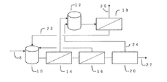
- the water to be treated 8 is supplied from the water tank 10 to be treated to the first reverse osmosis membrane device 14 by a pump (not shown), and the permeated water 15 is not shown from the first reverse osmosis membrane device 14.
- the water permeated from the second reverse osmosis membrane device 16 is supplied to the second reverse osmosis membrane device 16 by a pump, and the permeated water 17 from the second reverse osmosis membrane device 16 is supplied to the electroregenerative deionizing device (EDI) 20 by a pump (not shown). Connected to each other.
- EDI electroregenerative deionizing device
- the concentrated water 19 from the first reverse osmosis membrane device 14, the concentrated water 21 from the second reverse osmosis membrane device 16, and the concentrated water 24 from the EDI 20 are supplied to the brine tank 12, and these concentrated waters are supplied from the brine tank 12.
- the permeated water 23 from the third reverse osmosis membrane device 18 is collected in the water tank 10 to be treated, and the concentrated water 26 is discharged as a blow.
- An ultralow pressure to low pressure type reverse osmosis membrane device is used as the first reverse osmosis membrane device 14, and a high pressure type reverse osmosis membrane device is used as the second reverse osmosis membrane device 16.
- the first embodiment of the pure water production apparatus is configured as described above, and its operation will be described below.
- the water 8 to be treated supplied to the water tank 10 to be treated is supplied to the first low-pressure type to ultra-low pressure type reverse osmosis membrane device 14, and the permeated water 15 is supplied to the high-pressure type second reverse osmosis membrane device 16.
- the permeated water 17 is further supplied to the EDI20, and finally the treated water 22 is produced as pure water. Since the low-pressure type to ultra-low pressure type RO has a low removal rate of boron and urea, the permeated water of the first reverse osmosis membrane device 14 contains boron and urea.
- the second reverse osmosis membrane device effectively removes boron and urea.
- the concentrated water 19 from the first reverse osmosis membrane device 14, the concentrated water 21 from the second reverse osmosis membrane device 16, and the concentrated water 24 from the EDI 20 are supplied to the brine tank 12. Then, these concentrated waters are supplied to the third reverse osmosis membrane device 18, and the permeated water 23 is collected in the water tank 10 to be treated.
- the concentrated water 21 from the second reverse osmosis membrane device 16 and the concentrated water 24 from the EDI 20 have a lower concentration of impurities than the concentrated water 19 from the first reverse osmosis membrane device 14, so that the brine tank In 12, the concentrated water 19 from the first reverse osmosis membrane device 14 can be diluted.
- a low-pressure membrane and an ultra-low-pressure membrane that can be operated at a relatively low pressure are preferably used.
- the low-pressure membrane and ultra-low-pressure membrane those having an effective pressure of 1 MPa and a permeation flux of pure water at a water temperature of 25 ° C. of 0.65 to 1.8 m / d, preferably 0.65 to 1.0 m / d are used. be able to.
- the permeated flux is the amount of permeated water divided by the area of the reverse osmosis membrane.
- the "effective pressure” is the effective pressure acting on the membrane, which is described in JIS K3802: 2015 “Membrane Term", which is obtained by subtracting the osmotic pressure difference and the secondary lateral pressure from the average operating pressure.
- the average operating pressure is an average value of the pressure of the membrane supply water (operating pressure) and the pressure of the concentrated water (concentrated water outlet pressure) on the primary side of the reverse osmosis membrane, and is expressed by the following formula.
- the permeated flux per 1 MPa of effective pressure can be calculated from the information described in the catalog of the membrane manufacturer, for example, the amount of permeated water, the membrane area, the recovery rate at the time of evaluation, the NaCl concentration and the like.
- the average operating pressure / secondary side pressure of the pressure vessel the quality of water to be treated, the amount of permeated water, and the membranes. From the information such as the number of membranes, the permeation flux of the loaded membrane can be calculated.
- NITTO ES series ES15-D8, ES20-U8 product name
- HYDRANAUTICS ESPA series ESPAB, ESPA2, ESPA2-LD-MAX product name
- CPA series CPA series
- -MAX CPA7-LD product name
- Toray TMG series TMG-400, TMG20D-440 product name
- TM700 series TM720-440, TM720D-440 product name
- Dow Chemical BW series BW30HR, BW30XFR
- SG series SG30LE-440, SG30-400
- a high pressure type reverse osmosis membrane device is used.
- the high-pressure reverse osmosis membrane device was conventionally developed for desalination of seawater, but for water to be treated with a low salt concentration, it is possible to efficiently remove ions, TOC, etc. by lower operating pressure. It will be possible. For example, it is possible to realize the processing capacity of two stages of ultra-low pressure to low pressure type reverse osmosis membrane equipment in one stage if it is a high pressure type reverse osmosis membrane device.
- the third reverse osmosis membrane device may be either a low-pressure type or a high-pressure type, but a high-pressure type is preferable.
- the definition of "high pressure type" used in the second reverse osmosis membrane device can be given roughly the following properties. That is, the permeation flux of pure water at an effective pressure of 1 MPa and a water temperature of 25 ° C. is 0.2 to 0.65 m / d.
- the effective pressure of the high-pressure reverse osmosis membrane is preferably 1.5 to 2.0 MPa. By setting the effective pressure to 1.5 MPa or more, the boron blocking rate of the high-pressure reverse osmosis membrane can be sufficiently increased. Further, by setting the effective pressure to 2.0 MPa or more, a further effect of improving the boron blocking rate can be expected, but since it is necessary to increase the durable pressure of the apparatus, the equipment cost may increase.
- high-pressure reverse osmosis membrane examples include HYDRANAUTICS SWC series (SWC4, SWC5, SWC6) (trade name), Toray TM800 series (TM820V, TM820M) (trade name), and Dow Chemical SW series (SW30HRLE). , SW30ULE) (trade name) and the like.
- the reverse osmosis membrane device is composed of a reverse osmosis membrane module composed of members such as a reverse osmosis membrane and a flow path material, and one or more pressure vessels (vessels) loaded with one or more of them.
- a reverse osmosis membrane module composed of members such as a reverse osmosis membrane and a flow path material
- one or more pressure vessels vessels loaded with one or more of them.
- an amount of permeated water corresponding to the effective pressure can be obtained from the vessel.
- the water that does not permeate the membrane module and is concentrated in the vessel is discharged from the vessel as concentrated water.
- the shape of the reverse osmosis membrane module is not particularly limited, and a tubular type, spiral type, or hollow fiber type module can be used.
- each reverse osmosis membrane module is connected in series.
- the vessels can be installed in parallel or in series.
- the pumped water to be treated can be supplied to a plurality of vessels installed in parallel, and the permeated water and the concentrated water of each vessel can be merged and discharged from the apparatus.
- the concentrated water discharged from each vessel can be supplied to another vessel, which is a vessel configuration such as a so-called Christmas tree system.
- Appropriate module configurations and vessel configurations of these reverse osmosis membrane devices can be designed and selected according to the required permeated water quality, permeated water amount, water recovery rate, footprint, and the like.
- An appropriate water recovery rate can be designed and selected according to the water quality to be treated, the required permeated water quality, the permeated water amount, the water recovery rate, the footprint, and the like.
- the recovery rate of the first reverse osmosis device is 50 to 90%, preferably 65 to 85%, and the recovery rate of the second reverse osmosis membrane device is 80 to 99%, preferably 85 to 85.
- the recovery rate of the third reverse osmosis membrane device is 95%, and is 40 to 85%, preferably 60 to 80%.
- the water recovery rate of the second reverse osmosis membrane can be set to a high value because the impurity concentration is reduced by the first reverse osmosis membrane treatment.
- first, second and third reverse osmosis membrane devices chemicals (for example, reducing agent, pH adjuster, scale dispersant, bactericide, etc.) used in general reverse osmosis membrane devices can be used. it can.
- chemicals for example, reducing agent, pH adjuster, scale dispersant, bactericide, etc.
- the EDI is partitioned by an ion exchange membrane and has a desalting chamber filled with an ion exchanger, a concentrating chamber for concentrating the desalted ions in the desalting chamber, and an anode and a cathode for energizing an current. It is a device having a device that simultaneously performs deionization (desalination) treatment of water to be treated by an ion exchanger and regeneration treatment of the ion exchanger by energizing and operating a current.
- the water to be treated that has passed through the EDI is desalted by an ion exchanger filled in the desalination chamber and discharged to the outside of the EDI as EDI-treated water.
- the concentrated water in which ions are concentrated is discharged to the outside as EDI concentrated water.
- the EDI recovery rate is not particularly limited, but is preferably 90 to 95%.
- the water to be treated refers to the flow rate before the permeated water from the third reverse osmosis apparatus merges.
- the water recovery rate of this RO-EDI system is not particularly limited, but is 80 to 99%, preferably 85 to 95%. In this system, while recovering the concentrated water and EDI concentrated water of the second reverse osmosis apparatus, concentration in the system is not applied, so that both a high system recovery rate and a water recovery rate can be satisfied.
- the post-treatment device may be any device capable of performing ion removal treatment from EDI-treated water, dissolution gas removal treatment, TOC component removal treatment, etc., and is not particularly limited.
- regenerative ion exchange Devices non-regenerative ion exchange devices, degassing devices, UV oxidizing devices, membrane filtration devices and the like can be mentioned.
- these aftertreatment devices may be located between the RO system and the EDI system, or may be located between the first reverse osmosis membrane device and the second reverse osmosis membrane device. That is, the treated water of the first reverse osmosis membrane device and the treated water of the second reverse osmosis membrane device may be passed through the subsequent system after improving the water quality by post-treatment. For example, by degassing the permeated water of the first reverse osmosis membrane device and then passing water through the second reverse osmosis membrane device, it is possible to improve the inhibition rate of the ionic component, particularly the cation component.
- the water to be treated by the pure water apparatus used in the present invention is not particularly limited, but seawater desalination in which industrial water, groundwater, surface water, tap water, seawater, and seawater are desalinated by a back-penetration method or an evaporation method is used.
- Examples thereof include treated water, sewage, treated sewage water, various types of wastewater, for example, wastewater used in the semiconductor manufacturing process, and mixed water thereof.
- the pretreatment device may be any device capable of removing at least one of suspended solids, TOC component, oxidizing component, microorganisms, and ions in the water to be treated, and is not particularly limited. Examples thereof include a coagulation sedimentation device, a sand filtration device, a pressurized flotation device, a membrane filtration device, a softening device, and an activated carbon treatment device.
- the quality of the treated water (pure water) obtained in the present invention is not particularly limited, and examples thereof include those having a specific resistance of 17 M ⁇ ⁇ cm or more, a boron concentration of 50 ppt or less, a silica concentration of 100 ppt or less, and a TOC concentration of 5 ppb or less. ..
- the boron concentration is 1 ppt or less
- the silica concentration is 50 ppt or less
- the TOC concentration is 2 pppb or less.
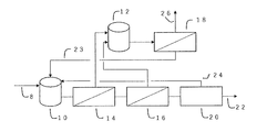
- the concentrated water from the second reverse osmosis membrane device 16 is collected in the water tank 10 to be treated instead of the brine tank 12.
- the concentration of impurities in the water tank to be treated is higher than that in the first aspect, but the concentrated water 24 from the EDI 20 is still supplied to the brine tank 12, and further in the third reverse osmosis membrane device 18. Since the permeated water 23 is treated and collected in the water tank 10 to be treated, the impurity concentration of the water to be treated as a whole is kept low.
- the concentrated water 24 from the EDI 20 is collected in the water tank 10 to be treated instead of the brine tank 12.
- the concentration of impurities in the water tank to be treated is higher than that in the first aspect, but the concentrated water from the second reverse osmosis membrane device 16 is still in the brine tank 12.
- the permeated water 23 is recovered in the water tank 10 to be treated by being further treated by the third reverse osmosis membrane device 18, so that the impurity concentration of the water to be treated as a whole is maintained low. Become.
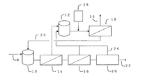
- a pH adjusting device 28 is provided upstream of the third reverse osmosis membrane device (between the brine tank 12 and the third reverse osmosis membrane device 18 in FIG. 4).
- the pH value to be adjusted can be appropriately determined depending on the situation, and for example, pH ⁇ 6.0 can be mentioned. Since the water in the brine tank contains a large amount of calcium and silica, the generation of scales derived from these can be suppressed by setting the pH in this range.
- the pH adjusting agent used here is not particularly limited as long as it has a function of adjusting pH, and for example, hydrochloric acid, sulfuric acid, nitric acid and the like can be used.
- the decarboxylation device 30 is provided upstream of the first reverse osmosis membrane 14 (water tank 10 to be treated).
- the permeated water 23 from the third reverse osmosis membrane device 18 is supplied together with the water 8 to be treated. This makes it possible to efficiently produce pure water when the CO 2 concentration of the water to be treated is high.
- the pH of the permeated water 23 from the third reverse osmosis membrane device is lowered by the pH adjusting device 28, the pH is lowered by mixing with the water to be treated 8.
- the lower the pH the more efficient the decarboxylation is, so that pure water can be produced more efficiently by the action of the pH adjusting device 28.
- the carbon dioxide component that could not be completely removed by the decarbonation device is concentrated in the water supplied by the third reverse osmosis device, the carbon dioxide concentration in the permeated water 23 of the third reverse osmosis device is higher than that of the water to be treated. Will also be higher.
- the decarboxylation device a decarbonation tower or a decarbonation film is used as the decarboxylation device.
- FIG. 6 a sixth embodiment according to the present invention will be described with reference to FIG.
- a plurality of electroregenerative deionizing devices 32 and 34 are connected in series instead of the EDI20 of the fifth embodiment.
- the concentrated water from the first-stage electroregenerative deionizing device 32 directly connected to the second reverse osmosis membrane device is supplied to the brine tank 12, and the second-stage and subsequent electroregenerating deionizing devices 34 Concentrated water is supplied between the second reverse osmosis membrane device 16 and the first-stage electroregenerative deionizing device 32.
- the EDI in a plurality of stages, pure water can be produced more efficiently.
- the impurity concentration of the concentrated water of the second and subsequent stages of the electroregenerative deionizing device is lower than the impurity concentration of the feed water of the first stage EDI, it is not necessary to supply the brine tank.
- Electric regeneration type deionizer (trade name: EDI-XP, manufactured by Organo Corporation), recovery rate 90%. The operating current value was set to 5A.
- Example 1 The operation was performed using the pure water production apparatus of the first embodiment shown in FIG. 1, and the water in the water tank to be treated and the permeated water from the second reverse osmosis membrane apparatus were of boron and urea. The concentration was measured. The results are shown in Table 2.
- Comparative Example 1 since the concentrated water from the second reverse osmosis membrane device having a high concentration of boron and the concentration of urea and the concentrated water from EDI are returned to the water to be treated and recovered, the inside of the water tank to be treated is recovered.
- the impurity concentration of the water permeated from the second reverse osmosis membrane device also increased accordingly.
- the concentrated water from the second reverse osmosis membrane device and the concentrated water from the EDI are supplied to the brine tank, and the permeated water of the third reverse osmosis membrane device is supplied to the water tank to be treated. Will be supplied.
- an increase in the concentration of impurities in the water tank to be treated was suppressed, and the water quality was improved.
- Examples 2 to 5, Comparative Example 2 Pure water is produced using the pure water production apparatus (Examples 2 to 5) of the present invention shown in FIGS. 1, 4 to 6 and the pure water production apparatus shown in FIG. 7 (Comparative Example 2), and finally.
- the water quality of the obtained treated water 22 (pure water) was evaluated.
- the specific resistance exceeded 18 M ⁇ ⁇ cm in both Examples 2 to 5 and Comparative Example 2.
- the boron concentration was less than 50 ppt in each of Examples 2 to 5, whereas it exceeded 50 ppt in Comparative Example 2.
- the urea concentration was less than 10 ppb in all of Examples 2 to 5, whereas it exceeded 12 ppb in Comparative Example 2.
- Water to be treated 10 Water to be treated 12 Blind tank 14 First reverse osmosis membrane device 15 Permeated water from the first reverse osmosis membrane device 16 Second reverse osmosis membrane device 17 From the second reverse osmosis membrane device Permeated water 18 Third reverse osmosis membrane device 19 Concentrated water from the first reverse osmosis membrane device 20 Electroregenerative deionization device (EDI) 21 Concentrated water from the second reverse osmosis membrane device 22 Treated water 23 Permeated water from the third reverse osmosis membrane device 24 Concentrated water from the electroregenerative deionization device 26 Blow 28 pH adjuster 30 Decarbonizer 32 1 Stage EDI 34 Second stage EDI
Landscapes
- Engineering & Computer Science (AREA)
- Water Supply & Treatment (AREA)
- Chemical & Material Sciences (AREA)
- Chemical Kinetics & Catalysis (AREA)
- Nanotechnology (AREA)
- Hydrology & Water Resources (AREA)
- Life Sciences & Earth Sciences (AREA)
- Environmental & Geological Engineering (AREA)
- Organic Chemistry (AREA)
- Health & Medical Sciences (AREA)
- Urology & Nephrology (AREA)
- Separation Using Semi-Permeable Membranes (AREA)
- Water Treatment By Electricity Or Magnetism (AREA)
Abstract
RO-EDIシステムを用いた新規な純水製造装置を提供する。被処理水が供給される第1の逆浸透膜装置と、前記第1の逆浸透膜装置からの透過水が供給される第2の逆浸透膜装置と、前記第2の逆浸透膜装置からの透過水が供給される電気再生式脱イオン装置と、前記第1の逆浸透膜装置からの濃縮水が供給されるブラインタンクと、前記ブラインタンクに接続する第3の逆浸透膜装置と、を備え、前記第2の逆浸透膜装置が高圧型逆浸透膜装置であって、前記ブラインタンクには、前記第2の逆浸透膜装置からの濃縮水および前記電気再生式脱イオン装置からの濃縮水からなる群より選択される少なくとも1種の濃縮水が供給され、前記第3の逆浸透膜装置からの透過水が、前記被処理水に供給される、純水製造装置を用いる。
Description
本発明は、純水の製造装置及び純水の製造方法に関する。
半導体装置の製造工程や液晶装置の製造工程における洗浄水等の用途として、有機物、イオン成分、微粒子、細菌等が高度に除去された超純水が使用されている。超純水製造装置は、一次純水系(純水製造装置)とサブシステムで構成される。純水製造装置としては、逆浸透膜(RO)装置と電気再生式脱イオン(EDI)装置を組み合わせたもの(RO-EDIシステム)が広く用いられている。そして、純水製造用のROとして、超低圧~低圧型逆浸透膜が使用されることが多い。
一方、半導体の線幅微細化に伴い、洗浄用として用いられる純水、超純水の要求水質が高まってきており、例えば、微量の不純物としてホウ素の低減が求められている。このため、ホウ素濃度を低減することを目的として、従来海水の淡水化用途で用いられるような高圧型逆浸透膜とイオン交換装置を組み合わせた方法が提案されている(特許文献1、特許文献2)。
また、RO装置の透過水の水質を向上させるため、複数段の低圧型RO装置を用い、1段目のRO装置の透過水を2段目以降のRO装置で処理し、得られた透過水をEDI装置に供給することが提案されている(特許文献3)。この場合、2段目以降のRO装置から排出される濃縮水中の不純物の濃度は、1段目のRO装置に供給される給水(被処理水)の不純物濃度と比較して低いため、2段目のRO装置からの濃縮水を被処理水に戻す(混合する)ことにより、被処理水を希釈しつつ、システム全体の水回収率を高めることが可能となる。また、同様の理由で、EDI装置から排出される濃縮水も被処理水に戻されることとなる。
さらに、水回収率を上げるために、1段目のRO装置の濃縮水を被処理水として第3のRO装置に通水し、得られた透過水を被処理水に戻すことも行われている。
一方、半導体の線幅微細化に伴い、洗浄用として用いられる純水、超純水の要求水質が高まってきており、例えば、微量の不純物としてホウ素の低減が求められている。このため、ホウ素濃度を低減することを目的として、従来海水の淡水化用途で用いられるような高圧型逆浸透膜とイオン交換装置を組み合わせた方法が提案されている(特許文献1、特許文献2)。
また、RO装置の透過水の水質を向上させるため、複数段の低圧型RO装置を用い、1段目のRO装置の透過水を2段目以降のRO装置で処理し、得られた透過水をEDI装置に供給することが提案されている(特許文献3)。この場合、2段目以降のRO装置から排出される濃縮水中の不純物の濃度は、1段目のRO装置に供給される給水(被処理水)の不純物濃度と比較して低いため、2段目のRO装置からの濃縮水を被処理水に戻す(混合する)ことにより、被処理水を希釈しつつ、システム全体の水回収率を高めることが可能となる。また、同様の理由で、EDI装置から排出される濃縮水も被処理水に戻されることとなる。
さらに、水回収率を上げるために、1段目のRO装置の濃縮水を被処理水として第3のRO装置に通水し、得られた透過水を被処理水に戻すことも行われている。
ここで、ホウ素除去を目的とする場合、2段目のRO装置として、1段目のRO装置よりホウ素除去性能の高い高圧型RO装置を使用することが考えられる。低圧型ROはホウ素の除去率が低く、1段目のRO装置が低圧型ROの場合、1段目のRO装置で除去し切れなかったホウ素が2段目のRO装置で濃縮され、濃縮水のホウ素濃度が被処理水より高くなってしまうケースが懸念される。被処理水よりも不純物濃度が高い水を被処理水に戻すと、被処理水に濃縮効果が働き、系内の不純物濃度が徐々に増加し、RO-EDIシステムの処理水質が低下するという問題が生じる。
本発明者らは、純水製造装置に関し、複数段RO-EDIシステムにおいて、2段目以降の少なくとも1段を高圧型ROにして、高圧型ROの濃縮水をさらにRO処理した透過水を被処理水に戻すことにより上記課題を解決することを見出した。
すなわち、本発明は、被処理水が供給される第1の逆浸透膜装置と、前記第1の逆浸透膜装置からの透過水が供給される第2の逆浸透膜装置と、前記第2の逆浸透膜装置からの透過水が供給される電気再生式脱イオン装置と、前記第1の逆浸透膜装置からの濃縮水が供給されるブラインタンクと、前記ブラインタンクに接続する第3の逆浸透膜装置と、を備え、前記第2の逆浸透膜装置が高圧型逆浸透膜装置であって、前記ブラインタンクには、前記第2の逆浸透膜装置からの濃縮水および前記電気再生式脱イオン装置からの濃縮水からなる群より選択される少なくとも1種の濃縮水が供給され、前記第3の逆浸透膜装置からの透過水が、前記被処理水に供給される、純水製造装置である。
すなわち、本発明は、被処理水が供給される第1の逆浸透膜装置と、前記第1の逆浸透膜装置からの透過水が供給される第2の逆浸透膜装置と、前記第2の逆浸透膜装置からの透過水が供給される電気再生式脱イオン装置と、前記第1の逆浸透膜装置からの濃縮水が供給されるブラインタンクと、前記ブラインタンクに接続する第3の逆浸透膜装置と、を備え、前記第2の逆浸透膜装置が高圧型逆浸透膜装置であって、前記ブラインタンクには、前記第2の逆浸透膜装置からの濃縮水および前記電気再生式脱イオン装置からの濃縮水からなる群より選択される少なくとも1種の濃縮水が供給され、前記第3の逆浸透膜装置からの透過水が、前記被処理水に供給される、純水製造装置である。
また、本発明は、(a)被処理水を第1の逆浸透膜装置に供給するステップと、(b)前記第1の逆浸透膜装置からの透過水を第2の逆浸透膜装置に供給するステップと、(c)前記第2の逆浸透膜装置からの透過水を電気再生式脱イオン装置に供給するステップと、(d)前記第1の逆浸透膜装置からの濃縮水をブラインタンクに供給するステップと、(e)前記第2の逆浸透膜装置からの濃縮水および前記電気再生式脱イオン装置からの濃縮水からなる群より選択される少なくとも1種の濃縮水をブラインタンクに供給するステップと、(f)前記ブラインタンクの濃縮水を第3の逆浸透膜装置に供給するステップと、(g)前記第3の逆浸透膜装置からの透過水を被処理水に供給するステップと、(h)前記電気再生式脱イオン装置からの処理水を純水として取り出すステップと、を備え、前記第2の逆浸透膜装置が高圧型逆浸透膜装置である、純水の製造方法である。
複数段RO-EDIシステムを有する純水製造装置において、水回収率を下げることなく、ホウ素が低減できる純水を製造することが可能となる。
まず、本発明に係る純水製造装置における第一の実施態様ついて、図1を参照しながら説明する。図1において、被処理水8が被処理水タンク10から、不図示のポンプによって第1の逆浸透膜装置14に供給され、第1の逆浸透膜装置14からその透過水15が不図示のポンプによって第2の逆浸透膜装置16に供給され、さらに第2の逆浸透膜装置16からの透過水17が不図示のポンプによって電気再生式脱イオン装置(EDI)20に供給されるように互いに接続されている。そして、第1の逆浸透膜装置14からの濃縮水19、第2の逆浸透膜装置16の濃縮水21およびEDI20のから濃縮水24はブラインタンク12に供給され、ブラインタンク12からこれら濃縮水が、不図示のポンプによって第3の逆浸透膜装置18に供給される。また、第3の逆浸透膜装置18からの透過水23は被処理水タンク10に回収され、濃縮水26はブローとして排出される。第1の逆浸透膜装置14として超低圧~低圧型の逆浸透膜装置が、第2の逆浸透膜装置16として高圧型の逆浸透膜装置が用いられる。
本発明に係る純水製造装置の第一の実施態様は、上記のように構成されており、以下、その作用について説明する。
被処理水タンク10に供給された被処理水8は、低圧型~超低圧型の第1の逆浸透膜装置14に供給され、その透過水15が高圧型の第2の逆浸透膜装置16に供給され、さらにその透過水17がEDI20に供給されて、最終的に処理水22が純水として製造される。低圧型~超低圧型ROは、ホウ素や尿素の除去率が低いため、第1の逆浸透膜装置14の透過水にはホウ素や尿素が含まれる。一方、高圧型ROは低圧型~超低圧型ROに比べホウ素や尿素の除去率が高いため、第2の逆浸透膜装置ではホウ素や尿素を効果的に除去される。第1の逆浸透膜装置14からの濃縮水19、第2の逆浸透膜装置16からの濃縮水21およびEDI20からの濃縮水24は、ブラインタンク12に供給される。そして、これらの濃縮水は、第3の逆浸透膜装置18に供給され、その透過水23が被処理水タンク10に回収されることとなる。ここで、第2の逆浸透膜装置16からの濃縮水21およびEDI20からの濃縮水24は、第1の逆浸透膜装置14からの濃縮水19に比べその不純物の濃度が低いため、ブラインタンク12において、第1の逆浸透膜装置14からの濃縮水19を希釈することができる。
被処理水タンク10に供給された被処理水8は、低圧型~超低圧型の第1の逆浸透膜装置14に供給され、その透過水15が高圧型の第2の逆浸透膜装置16に供給され、さらにその透過水17がEDI20に供給されて、最終的に処理水22が純水として製造される。低圧型~超低圧型ROは、ホウ素や尿素の除去率が低いため、第1の逆浸透膜装置14の透過水にはホウ素や尿素が含まれる。一方、高圧型ROは低圧型~超低圧型ROに比べホウ素や尿素の除去率が高いため、第2の逆浸透膜装置ではホウ素や尿素を効果的に除去される。第1の逆浸透膜装置14からの濃縮水19、第2の逆浸透膜装置16からの濃縮水21およびEDI20からの濃縮水24は、ブラインタンク12に供給される。そして、これらの濃縮水は、第3の逆浸透膜装置18に供給され、その透過水23が被処理水タンク10に回収されることとなる。ここで、第2の逆浸透膜装置16からの濃縮水21およびEDI20からの濃縮水24は、第1の逆浸透膜装置14からの濃縮水19に比べその不純物の濃度が低いため、ブラインタンク12において、第1の逆浸透膜装置14からの濃縮水19を希釈することができる。
本発明で用いる低圧型逆浸透装置に使用される膜は、比較的低い圧力で運転が可能である低圧膜、超低圧膜が好適に使用される。低圧膜、超低圧膜としては、有効圧力1MPa、水温25℃における純水の透過流束が0.65~1.8m/d、好ましくは0.65~1.0m/dのものを使用することができる。
ここで、透過流束は、透過水量を逆浸透膜面積で割ったものである。「有効圧力」とは、JIS K3802:2015「膜用語」に記載の、平均操作圧から浸透圧差及び2次側圧を差し引いた、膜に働く有効な圧である。なお、平均操作圧は、逆浸透膜の1次側における膜供給水の圧力(運転圧力)と濃縮水の圧力(濃縮水出口圧力)の平均値であり、以下の式により表される。
平均操作圧=(運転圧力+濃縮水出口圧力)/2
有効圧力1MPaあたりの透過流束は、膜メーカーのカタログに記載の情報、例えば、透過水量、膜面積、評価時の回収率、NaCl濃度等から計算することができる。また、1つ又は複数の圧力容器に同一の透過流束である逆浸透膜が複数本装填されている場合、圧力容器の平均操作圧/2次側圧力、被処理水水質、透過水量、膜本数等の情報より、装填された膜の透過流束を計算することができる。
平均操作圧=(運転圧力+濃縮水出口圧力)/2
有効圧力1MPaあたりの透過流束は、膜メーカーのカタログに記載の情報、例えば、透過水量、膜面積、評価時の回収率、NaCl濃度等から計算することができる。また、1つ又は複数の圧力容器に同一の透過流束である逆浸透膜が複数本装填されている場合、圧力容器の平均操作圧/2次側圧力、被処理水水質、透過水量、膜本数等の情報より、装填された膜の透過流束を計算することができる。
低圧~超低圧型逆浸透膜として、例えば、NITTO製ESシリーズ(ES15-D8、ES20-U8商品名)、HYDRANAUTICS製ESPAシリーズ(ESPAB、ESPA2、ESPA2-LD-MAX商品名)、CPAシリーズ(CPA5‐MAX、CPA7-LD商品名)、東レ製TMGシリーズ(TMG20‐400、TMG20D-440商品名)、TM700シリーズ(TM720-440、TM720D-440商品名)、ダウケミカル社製BWシリーズ(BW30HR、BW30XFR-400/34i)、SGシリーズ(SG30LE-440、SG30-400)、FORTILIFE CR100などが挙げられる。
本発明において、第2の逆浸透膜装置は、高圧型のものが用いられる。高圧型逆浸透膜装置は、従来海水淡水化用として開発されたものであるが、塩濃度の低い被処理水に対しては、より低い運転圧力によって、効率的なイオンやTOC等の除去が可能となる。例えば、超低圧~低圧型逆浸透膜装置2段分の処理能力を、高圧型逆浸透膜装置であれば1段で実現することも可能である。このような逆浸透膜装置を用いることで、超低圧~低圧膜では十分に除去できなかったシリカ、ホウ素、尿素、エタノール、イソプロピルアルコールといった非解離物質の除去率を飛躍的に上昇させることが可能である。また、第3の逆浸透膜装置は、低圧型あるいは高圧型のいずれであってもよいが、高圧型のものが好ましい。第3の逆浸透膜装置を高圧型逆浸透装置にすることで、第3の逆浸透膜装置からの透過水23の水質が向上し、被処理水の希釈効果を高めることができる。結果として、EDI処理水の向上につながることとなる。
本発明において、第2の逆浸透膜装置に用いられる「高圧型」の定義としては、おおよそ、次の性質を示すものを挙げることができる。すなわち、有効圧力1MPa、水温25℃における純水の透過流束が0.2~0.65m/dのものである。高圧型逆浸透膜の有効圧力は、1.5~2.0MPaであることが好ましい。有効圧力を1.5MPa以上にすることで、高圧型逆浸透膜のほう素阻止率を十分に高めることができる。また、有効圧力を2.0MPa以上にすることで、更なるホウ素阻止率向上効果が見込めるが、装置の耐久圧力を高める必要があるため、設備費用が増加する場合がある。
高圧型逆浸透膜としては、例えば、HYDRANAUTICS社製SWCシリーズ(SWC4、SWC5、SWC6)(商品名)、東レ社製TM800シリーズ(TM820V、TM820M)(商品名)、ダウケミカル社製SWシリーズ(SW30HRLE、SW30ULE)(商品名)などを挙げることができる。
次に、本発明における逆浸透膜装置について説明する。逆浸透膜装置は、逆浸透膜や流路材といった部材から構成された逆浸透膜モジュールと、それが一つ以上装填された、一つ以上の圧力容器(ベッセル)から構成される。膜モジュールが装填されたベッセルに被処理水を圧送することで、有効圧力に見合った量の透過水がベッセルから得られる。また、膜モジュールを透過せず、ベッセル内で濃縮された水は、濃縮水としてベッセルから排出される。逆浸透膜モジュールの形状に特に制限はなく、チューブラー型、スパイラル型、中空糸型モジュールを使用することができる。同一ベッセル内で複数の逆浸透膜モジュールを使用する場合は、各逆浸透膜モジュールは直列に接続される。逆浸透装置で複数本のベッセルを用いる場合、ベッセルは並列もしくは直列に設置することができる。たとえば、圧送された被処理水を、並列に設置された複数本のベッセルに供給し、各ベッセルの透過水および濃縮水を合流させて装置から排出することができる。さらに、各ベッセルから排出された濃縮水を、別のベッセルに供給する、いわゆるクリスマスツリー方式のようなベッセル構成にすることができる。
これら逆浸透膜装置のモジュール構成、ベッセル構成は、求められる透過水質、透過水量、水回収率、フットプリント等によって、適切なものを設計、選定することができる。
これら逆浸透膜装置のモジュール構成、ベッセル構成は、求められる透過水質、透過水量、水回収率、フットプリント等によって、適切なものを設計、選定することができる。
本発明で用いられる各逆浸透膜装置の水回収率は、各逆浸透膜装置の被処理水と、各逆浸透膜装置で得られる透過水の比率によって算出される。すなわち、各逆浸透膜装置の回収率=(各逆浸透膜装置により得られる透過水量)/(各逆浸透膜装置に供給される被処理水量)である。水回収率は、被処理水水質、求められる透過水質、透過水量、水回収率、フットプリント等によって、適切なものを設計、選定することができる。これらに特に制限はないが、第1の逆浸透装置の回収率は50~90%、好ましくは65~85%、第2の逆浸透膜装置の回収率は80~99%、好ましくは85~95%、第3の逆浸透膜装置の回収率は40~85%、好ましくは60~80%である。特に第2の逆浸透膜の水回収率は、第1の逆浸透膜処理により不純物濃度が低下していることから、高い値を設定することができる。
また、第1及び第2、第3の逆浸透膜装置では、一般的な逆浸透膜装置に用いられる薬品(例えば、還元剤、pH調整剤、スケール分散剤、殺菌剤等)を用いることができる。
次に、本発明で用いられるEDIについて説明する。EDIは、イオン交換膜にて区画され、イオン交換体が充填された脱塩室と、脱塩室にて脱塩されたイオンを濃縮する濃縮室と、電流を通電するための陽極と陰極を有する装置であり、電流を通電して運転することで、イオン交換体による被処理水の脱イオン化(脱塩)処理と、イオン交換体の再生処理とを同時に行う装置である。EDIに通水された被処理水は、脱塩室に充填されたイオン交換体によって脱塩され、EDI処理水としてEDI外部に排出される。同様に、イオン類が濃縮された濃縮水は、EDI濃縮水として外部に排出される。
EDIの回収率は、EDIに供給される被処理水量と、得られる処理水量によって算出される。すなわち、EDI回収率=(EDI処理水流量)/(EDI被処理水量)である。EDI回収率に特に制限はないが、90~95%であることが好ましい。
RO-EDIシステムの回収率は、被処理水量と、EDIによって得られる処理水量の比率によって算出される。すなわち、RO-EDIシステムの回収率=EDI処理水量/被処理水量である。ここでの被処理水は、第3の逆浸透装置からの透過水が合流する前の流量を指す。本RO-EDIシステムの水回収率に特に制限はないが、80~99%、好ましくは85~95%である。本システムでは第2の逆浸透装置の濃縮水、EDI濃縮水を回収しつつ、系内の濃縮がかからないため、高いシステム回収率と水回収率の両方を満足することができる。
EDI処理水について、後処理を実施することにより、RO-EDIシステムで得られた透過水の水質をさらに向上さえることができる。後処理装置としては、EDI処理水からのイオン除去処理、溶存気体の除去処理、TOC成分の除去処理等を行うことができるものであればよく、特に制限はないが、例えば、再生式イオン交換装置、非再生式イオン交換装置、脱気装置、UV酸化装置、膜ろ過装置等が挙げられる。
なお、これら後処理装置は、ROシステムとEDIシステムの間にあってもよいし、また、第一の逆浸透膜装置と第二の逆浸透膜装置の中間にあってもよい。すなわち、第一の逆浸透膜装置の処理水や、第二の逆浸透膜装置の処理水について、後処理により水質を向上させたのち、後段のシステムに通水してもよい。例えば第一の逆浸透膜装置の透過水を脱気処理してから第二の逆浸透膜装置に通水することで、イオン成分、特にカチオン成分の阻止率を向上させることが可能である。
本発明に用いられる純水装置の被処理水としては、特に制限はないが、工水、地下水、表層水、水道水、海水、海水を逆浸透法または蒸発法等によって脱塩した海水淡水化処理水、下水、下水処理水、各種排水、例えば半導体製造工程で使用された排水、これらの混合水が挙げられる。被処理水成分として、導電率10~1000μS/cm、TDS=5~500ppm、ホウ素濃度10ppb~10ppm、尿素濃度1~100ppbのいずれか一つ以上を満たすことが好ましい。
被処理水は、逆浸透膜装置に導入される前、前処理により、被処理水中の不純物が除去されていることが望ましい。前処理装置としては、被処理水中の懸濁物質、TOC成分、酸化性成分、微生物、およびイオンのうち少なくとも1つを除去することができるものであればよく、特に制限はないが、例えば、凝集沈殿装置、砂ろ過装置、加圧浮上装置、膜ろ過装置、軟化装置、活性炭処理装置等が挙げられる。
本発明で得られる処理水(純水)の水質としては、特に制限はないが、比抵抗17MΩ・cm以上、ホウ素濃度50ppt以下、シリカ濃度100ppt以下、TOC濃度5ppb以下のものを挙げることができる。好ましくは、ホウ素濃度1ppt以下、シリカ濃度50ppt以下、TOC濃度2ppb以下である。
次に、本発明に係る第二の実施態様について、図2を参照して説明する。図2において、第一の実施態様に比べ、第2の逆浸透膜装置16からの濃縮水がブラインタンク12ではなく、被処理水タンク10に回収されている。この場合、被処理水タンク内の不純物濃度が上記第一の態様に比べて高くなるが、EDI20からの濃縮水24は、依然ブラインタンク12に供給され、さらに第3の逆浸透膜装置18で処理されてその透過水23が被処理水タンク10に回収されるため、全体としての被処理水の不純物濃度は、低く維持されることとなる。
次に、本発明に係る第三の実施態様について、図3を参照して説明する。図3において、第一の実施態様に比べ、EDI20からの濃縮水24がブラインタンク12ではなく、被処理水タンク10に回収されている。この場合、第二の態様と同様に、被処理水タンク内の不純物濃度が上記第一の態様に比べて高くなるが、第2の逆浸透膜装置16からの濃縮水は、依然ブラインタンク12に供給され、さらに第3の逆浸透膜装置18で処理されてその透過水23が被処理水タンク10に回収されるため、全体としての被処理水の不純物濃度は、低く維持されることとなる。
次に、本発明に係る第四の実施態様について、図4を参照して説明する。図4において、第一の実施態様に加え、第3の逆浸透膜装置の上流(図4では、ブラインタンク12と第3の逆浸透膜装置18との間)に、pH調整装置28が備えられている。これにより、第3の逆浸透膜装置18に供給される水のpHを調整することができる。調整するpHの値としては、状況により適宜決定することができるが、例えばpH<6.0とすることが挙げられる。ブラインタンクの水中には、カルシウムやシリカが多く含まれるため、このpHの範囲にすることにより、これらに由来するスケールの発生を抑えることができる。
ここで用いられるpH調整剤としては、pHを調整する働きを有するものであれば特に制限はないが、例えば、塩酸、硫酸、硝酸等を用いることができる。
ここで用いられるpH調整剤としては、pHを調整する働きを有するものであれば特に制限はないが、例えば、塩酸、硫酸、硝酸等を用いることができる。
次に、本発明に係る第五の実施態様について、図5を参照して説明する。図5において、第四の実施態様に加え、第1の逆浸透膜14(被処理水タンク10)の上流に脱炭酸装置30が備えられている。該脱炭酸装置30は、被処理水8が供給されると伴に、第3の逆浸透膜装置18からの透過水23が供給される。これにより、被処理水のCO2濃度が高いときに、効率的に純水を製造することが可能となる。このとき、第3の逆浸透膜装置からの透過水23は、pH調整装置28によってpHが低くなっているため、被処理水8と混合することによりpHは低下する。ここで、脱炭酸はpHが低いほど効率がよいことが知られているので、pH調整装置28の働きにより、さらに効率的に純水が製造できることとなる。さらに、第3の逆浸透装置の供給水には、脱炭酸装置でとりきれなかった炭酸成分が濃縮されているため、第3の逆浸透装置の透過水23中の炭酸濃度は被処理水よりも高くなる。これを脱炭酸処理してから被処理水タンク10に合流させることで、システム全体の炭酸濃度を低下させる効果が期待できる。脱炭酸装置としては、脱炭酸塔や脱炭酸膜が用いられる。
次に、本発明に係る第六の実施態様について、図6を参照して説明する。図6において、第五の実施態様のEDI20に代えて、複数の電気再生式脱イオン装置32並びに34が直列に接続されている。そして、第2の逆浸透膜装置に直接接続する1段目の電気再生式脱イオン装置32からの濃縮水がブラインタンク12に供給され、2段目以降の電気再生式脱イオン装置34からの濃縮水が、第2の逆浸透膜装置16と1段目の電気再生式脱イオン装置32との間に供給される。
EDIを複数段とすることにより、より効率的に純水の製造が可能となる。このとき、2段目以降の電気再生式脱イオン装置の濃縮水の不純物濃度は、1段目のEDIの給水の不純物濃度よりも低いため、ブラインタンクに供給する必要はない。
EDIを複数段とすることにより、より効率的に純水の製造が可能となる。このとき、2段目以降の電気再生式脱イオン装置の濃縮水の不純物濃度は、1段目のEDIの給水の不純物濃度よりも低いため、ブラインタンクに供給する必要はない。
なお、上述した本発明に係る実施態様は一例を示したものであって、本発明は上記態様に限定されるものではない。
以下、実施例を用いて本発明をさらに詳細に説明するが、本発明は以下の実施例に限定されるものではない。
実施例及び比較例で用いた被処理水としては、以下のものを使用した。
被処理水20m3/hに対して、ナトリウムが20ppm、カルシウムが20ppm、炭酸水素イオンが30ppmCaCO3、イオン状シリカが10ppm、ホウ素が50ppb、尿素が20ppbであり、約50h運転した。
実施例及び比較例で用いた被処理水としては、以下のものを使用した。
被処理水20m3/hに対して、ナトリウムが20ppm、カルシウムが20ppm、炭酸水素イオンが30ppmCaCO3、イオン状シリカが10ppm、ホウ素が50ppb、尿素が20ppbであり、約50h運転した。
また、純水製造装置としては、以下の逆浸透膜装置およびEDIを備えるものを使用し、運転時のpHは次のようであった。
第1の逆浸透膜装置:逆浸透膜(商品名:CPA5-LD、Hydranautics社製)、回収率80%、pH=8.0。
第2の逆浸透膜装置:逆浸透膜(商品名:SW30HRLE-440、ダウケミカル社製)、回収率90%、pH=8.5。
第3の逆浸透膜装置:逆浸透膜(商品名:SWC5-LD、Hydranautics社製)、回収率75%、pH=6。
電気再生式脱イオン装置:(商品名:EDI-XP、オルガノ社製)、回収率90%。 なお、運転電流値は5Aに設定した。
第1の逆浸透膜装置:逆浸透膜(商品名:CPA5-LD、Hydranautics社製)、回収率80%、pH=8.0。
第2の逆浸透膜装置:逆浸透膜(商品名:SW30HRLE-440、ダウケミカル社製)、回収率90%、pH=8.5。
第3の逆浸透膜装置:逆浸透膜(商品名:SWC5-LD、Hydranautics社製)、回収率75%、pH=6。
電気再生式脱イオン装置:(商品名:EDI-XP、オルガノ社製)、回収率90%。 なお、運転電流値は5Aに設定した。
[比較例1]
図7に示す純水製造装置を用いて運転を行い、被処理水タンクの水、および第2の逆浸透膜装置からの透過水について、ホウ素及び尿素の濃度を測定した。結果を表1に示す。
図7に示す純水製造装置を用いて運転を行い、被処理水タンクの水、および第2の逆浸透膜装置からの透過水について、ホウ素及び尿素の濃度を測定した。結果を表1に示す。

[実施例1]
図1に示す本発明に係る第一の実施形態の純水製造装置を用いて運転を行い、被処理水タンクの水、および第2の逆浸透膜装置からの透過水について、ホウ素及び尿素の濃度を測定した。結果を表2に示す。
図1に示す本発明に係る第一の実施形態の純水製造装置を用いて運転を行い、被処理水タンクの水、および第2の逆浸透膜装置からの透過水について、ホウ素及び尿素の濃度を測定した。結果を表2に示す。

比較例1においては、ホウ素の濃度及び尿素の濃度の高い第2の逆浸透膜装置からの濃縮水およびEDIからの濃縮水を被処理水に戻して回収しているため、被処理水タンク内の不純物濃度が上昇し、これに伴い、第2の逆浸透膜装置からの透過水の不純物濃度も上昇することとなった。
一方、実施例1においては、第2の逆浸透膜装置からの濃縮水およびEDIからの濃縮水をブラインタンクに供給しており、第3の逆浸透膜装置の透過水が被処理水タンクに供給される。これにより被処理水タンク内の不純物濃度の上昇が抑えられ、水質が向上した。
一方、実施例1においては、第2の逆浸透膜装置からの濃縮水およびEDIからの濃縮水をブラインタンクに供給しており、第3の逆浸透膜装置の透過水が被処理水タンクに供給される。これにより被処理水タンク内の不純物濃度の上昇が抑えられ、水質が向上した。
[実施例2~5、比較例2]
図1、4~6に示した本発明の純水製造装置(実施例2~5)及び図7に示した純水製造装置(比較例2)を用いて純水を製造し、最終的に得られた処理水22(純水)の水質を評価した。
その結果、実施例2~5、比較例2のいずれにおいても、比抵抗は18MΩ・cmを超えていた。
また、ホウ素濃度は、実施例2~5のいずれも50ppt未満であったのに対し、比較例2では50pptを超えていた。
尿素濃度は、実施例2~5のいずれも10ppb未満であったのに対し、比較例2では12ppbを超えていた。
図1、4~6に示した本発明の純水製造装置(実施例2~5)及び図7に示した純水製造装置(比較例2)を用いて純水を製造し、最終的に得られた処理水22(純水)の水質を評価した。
その結果、実施例2~5、比較例2のいずれにおいても、比抵抗は18MΩ・cmを超えていた。
また、ホウ素濃度は、実施例2~5のいずれも50ppt未満であったのに対し、比較例2では50pptを超えていた。
尿素濃度は、実施例2~5のいずれも10ppb未満であったのに対し、比較例2では12ppbを超えていた。
8 被処理水
10 被処理水タンク
12 ブラインタンク
14 第1の逆浸透膜装置
15 第1の逆浸透膜装置からの透過水
16 第2の逆浸透膜装置
17 第2の逆浸透膜装置からの透過水
18 第3の逆浸透膜装置
19 第1の逆浸透膜装置からの濃縮水
20 電気再生式脱イオン装置(EDI)
21 第2の逆浸透膜装置からの濃縮水
22 処理水
23 第3の逆浸透膜装置からの透過水
24 電気再生式脱イオン装置からの濃縮水
26 ブロー
28 pH調整装置
30 脱炭酸装置
32 1段目のEDI
34 2段目のEDI
10 被処理水タンク
12 ブラインタンク
14 第1の逆浸透膜装置
15 第1の逆浸透膜装置からの透過水
16 第2の逆浸透膜装置
17 第2の逆浸透膜装置からの透過水
18 第3の逆浸透膜装置
19 第1の逆浸透膜装置からの濃縮水
20 電気再生式脱イオン装置(EDI)
21 第2の逆浸透膜装置からの濃縮水
22 処理水
23 第3の逆浸透膜装置からの透過水
24 電気再生式脱イオン装置からの濃縮水
26 ブロー
28 pH調整装置
30 脱炭酸装置
32 1段目のEDI
34 2段目のEDI
Claims (10)
- 被処理水が供給される第1の逆浸透膜装置と、
前記第1の逆浸透膜装置からの透過水が供給される第2の逆浸透膜装置と、
前記第2の逆浸透膜装置からの透過水が供給される電気再生式脱イオン装置と、
前記第1の逆浸透膜装置からの濃縮水が供給されるブラインタンクと、
前記ブラインタンクに接続する第3の逆浸透膜装置と、を備え、
前記第2の逆浸透膜装置が高圧型逆浸透膜装置であって、
前記ブラインタンクには、前記第2の逆浸透膜装置からの濃縮水および前記電気再生式脱イオン装置からの濃縮水からなる群より選択される少なくとも1種の濃縮水が供給され、
前記第3の逆浸透膜装置からの透過水が、前記被処理水に供給される、純水製造装置。 - 前記第3の逆浸透膜装置が高圧型逆浸透膜装置である、請求項1に記載の純水製造装置。
- 前記第3の逆浸透膜装置の上流にpH調整装置をさらに備える、請求項1または2に記載の純水製造装置。
- 前記第1の逆浸透膜装置の上流に脱炭酸装置を備え、被処理水および前記第3の逆浸透膜装置からの透過水が前記脱炭酸装置に供給される、請求項1~3のいずれか1項に記載の純水製造装置。
- 前記電気再生式脱イオン装置が直列に接続された複数段の電気再生式脱イオン装置から構成され、前記第2の逆浸透膜装置に直接接続する1段目の電気再生式脱イオン装置からの濃縮水が前記ブラインタンクに供給され、2段目以降の電気再生式脱イオン装置からの濃縮水が、前記第2の逆浸透膜装置と前記1段目の電気再生式脱イオン装置の間に供給される、請求項1~4のいずれか1項に記載の純水製造装置。
- (a)被処理水を第1の逆浸透膜装置に供給するステップと、
(b)前記第1の逆浸透膜装置からの透過水を第2の逆浸透膜装置に供給するステップと、
(c)前記第2の逆浸透膜装置からの透過水を電気再生式脱イオン装置に供給するステップと、
(d)前記第1の逆浸透膜装置からの濃縮水をブラインタンクに供給するステップと、
(e)前記第2の逆浸透膜装置からの濃縮水および前記電気再生式脱イオン装置からの濃縮水からなる群より選択される少なくとも1種の濃縮水をブラインタンクに供給するステップと、
(f)前記ブラインタンクの濃縮水を第3の逆浸透膜装置に供給するステップと、
(g)前記第3の逆浸透膜装置からの透過水を被処理水に供給するステップと、
(h)前記電気再生式脱イオン装置からの処理水を純水として取り出すステップと、
を備え、前記第2の逆浸透膜装置が高圧型逆浸透膜装置である、純水の製造方法。 - 前記第2の逆浸透膜装置および前記第3の逆浸透膜装置の少なくとも一方が、高圧型逆浸透膜装置である、請求項6に記載の純水の製造方法。
- 前記第3の逆浸透膜装置の上流でpHを調整するステップをさらに備える、請求項6または7に記載の純水の製造方法。
- 前記第1の逆浸透膜装置の上流に備えられた脱炭酸装置に、被処理水および前記第3の逆浸透膜装置からの透過水を供給するステップをさらに備える、請求項6~8のいずれか1項に記載の純水の製造方法。
- 前記電気再生式脱イオン装置が直列に接続された複数段の電気再生式脱イオン装置から構成され、前記第2の逆浸透膜装置に直接接続する1段目の電気再生式脱イオン装置からの濃縮水を前記ブラインタンクに供給し、2段目以降の電気再生式脱イオン装置からの濃縮水を、前記第2の逆浸透膜装置と前記1段目の電気再生式脱イオン装置の間に供給するステップをさらに備える、請求項6~9のいずれか1項に記載の純水の製造方法。
Priority Applications (2)
| Application Number | Priority Date | Filing Date | Title |
|---|---|---|---|
| US17/437,975 US12172917B2 (en) | 2019-03-13 | 2020-02-13 | Pure-water production device and pure-water production method |
| CN202080020663.3A CN113613761A (zh) | 2019-03-13 | 2020-02-13 | 纯水制造装置及纯水的制造方法 |
Applications Claiming Priority (2)
| Application Number | Priority Date | Filing Date | Title |
|---|---|---|---|
| JP2019045327A JP7200014B2 (ja) | 2019-03-13 | 2019-03-13 | 純水製造装置および純水の製造方法 |
| JP2019-045327 | 2019-03-13 |
Publications (1)
| Publication Number | Publication Date |
|---|---|
| WO2020184044A1 true WO2020184044A1 (ja) | 2020-09-17 |
Family
ID=72427934
Family Applications (1)
| Application Number | Title | Priority Date | Filing Date |
|---|---|---|---|
| PCT/JP2020/005550 Ceased WO2020184044A1 (ja) | 2019-03-13 | 2020-02-13 | 純水製造装置および純水の製造方法 |
Country Status (5)
| Country | Link |
|---|---|
| US (1) | US12172917B2 (ja) |
| JP (1) | JP7200014B2 (ja) |
| CN (1) | CN113613761A (ja) |
| TW (1) | TWI826657B (ja) |
| WO (1) | WO2020184044A1 (ja) |
Cited By (2)
| Publication number | Priority date | Publication date | Assignee | Title |
|---|---|---|---|---|
| CN115461133A (zh) * | 2020-10-14 | 2022-12-09 | 野村微科学股份有限公司 | 液体处理装置、纯水制造系统以及液体处理方法 |
| EP4431465A4 (en) * | 2021-11-09 | 2025-11-12 | Kurita Water Ind Ltd | MULTI-STAGE REVERSE OSMOSIS MEMBRANE TREATMENT SYSTEM |
Families Citing this family (5)
| Publication number | Priority date | Publication date | Assignee | Title |
|---|---|---|---|---|
| JP7621872B2 (ja) * | 2021-04-22 | 2025-01-27 | オルガノ株式会社 | 水処理方法および水処理装置 |
| JP7318755B1 (ja) * | 2022-03-03 | 2023-08-01 | 栗田工業株式会社 | 脱塩装置の運転方法 |
| JP7757835B2 (ja) * | 2022-03-04 | 2025-10-22 | 王子ホールディングス株式会社 | 水処理システム及び水処理方法 |
| WO2024048115A1 (ja) * | 2022-08-31 | 2024-03-07 | オルガノ株式会社 | 水処理システムおよび水処理方法 |
| DE102023107305A1 (de) | 2023-03-23 | 2024-09-26 | Kärcher Futuretech GmbH | Mobile wasseraufbereitungsanlage zum erzeugen von trinkwasser in einem katastrophengebiet |
Citations (5)
| Publication number | Priority date | Publication date | Assignee | Title |
|---|---|---|---|---|
| JPH04150923A (ja) * | 1990-10-12 | 1992-05-25 | Kawasaki Heavy Ind Ltd | 低圧用逆浸透膜による高濃度溶液の濃縮方法及び装置 |
| JP2004000919A (ja) * | 2002-04-05 | 2004-01-08 | Kurita Water Ind Ltd | 脱塩水製造装置 |
| JP2004167423A (ja) * | 2002-11-21 | 2004-06-17 | Kurita Water Ind Ltd | 純水製造装置及び純水製造方法 |
| WO2015012054A1 (ja) * | 2013-07-22 | 2015-01-29 | 栗田工業株式会社 | ホウ素含有水の処理方法及び装置 |
| JP2016150275A (ja) * | 2015-02-16 | 2016-08-22 | 栗田工業株式会社 | 純水の製造方法及び純水の製造装置 |
Family Cites Families (8)
| Publication number | Priority date | Publication date | Assignee | Title |
|---|---|---|---|---|
| US5238574A (en) | 1990-06-25 | 1993-08-24 | Kawasaki Jukogyo Kabushiki Kaisha | Method and apparatus having reverse osmosis membrane for concentrating solution |
| JP4351559B2 (ja) * | 2004-03-05 | 2009-10-28 | 株式会社神鋼環境ソリューション | 海水淡水化方法 |
| JPWO2008059824A1 (ja) * | 2006-11-16 | 2010-03-04 | 栗田工業株式会社 | 水処理装置および水処理方法 |
| JP2009028695A (ja) * | 2007-07-30 | 2009-02-12 | Kurita Water Ind Ltd | 純水製造装置及び純水製造方法 |
| WO2016033319A1 (en) * | 2014-08-27 | 2016-03-03 | Tangent Company Llc | Electrochemically regenerated water decationization method and apparatus |
| JP6228531B2 (ja) | 2014-12-19 | 2017-11-08 | 栗田工業株式会社 | 超純水製造装置及び超純水製造方法 |
| CN205419944U (zh) * | 2015-11-24 | 2016-08-03 | 凯芙隆(厦门)环境科技有限公司 | 一种双渗透净水机及其的滤芯模组 |
| CN207596652U (zh) * | 2017-11-17 | 2018-07-10 | 中煤西安设计工程有限责任公司 | 一种高矿化度矿井水近零排放综合资源化pdces处理系统 |
-
2019
- 2019-03-13 JP JP2019045327A patent/JP7200014B2/ja active Active
-
2020
- 2020-02-13 US US17/437,975 patent/US12172917B2/en active Active
- 2020-02-13 CN CN202080020663.3A patent/CN113613761A/zh active Pending
- 2020-02-13 WO PCT/JP2020/005550 patent/WO2020184044A1/ja not_active Ceased
- 2020-02-27 TW TW109106380A patent/TWI826657B/zh active
Patent Citations (5)
| Publication number | Priority date | Publication date | Assignee | Title |
|---|---|---|---|---|
| JPH04150923A (ja) * | 1990-10-12 | 1992-05-25 | Kawasaki Heavy Ind Ltd | 低圧用逆浸透膜による高濃度溶液の濃縮方法及び装置 |
| JP2004000919A (ja) * | 2002-04-05 | 2004-01-08 | Kurita Water Ind Ltd | 脱塩水製造装置 |
| JP2004167423A (ja) * | 2002-11-21 | 2004-06-17 | Kurita Water Ind Ltd | 純水製造装置及び純水製造方法 |
| WO2015012054A1 (ja) * | 2013-07-22 | 2015-01-29 | 栗田工業株式会社 | ホウ素含有水の処理方法及び装置 |
| JP2016150275A (ja) * | 2015-02-16 | 2016-08-22 | 栗田工業株式会社 | 純水の製造方法及び純水の製造装置 |
Cited By (4)
| Publication number | Priority date | Publication date | Assignee | Title |
|---|---|---|---|---|
| CN115461133A (zh) * | 2020-10-14 | 2022-12-09 | 野村微科学股份有限公司 | 液体处理装置、纯水制造系统以及液体处理方法 |
| CN115461133B (zh) * | 2020-10-14 | 2023-12-05 | 野村微科学股份有限公司 | 液体处理装置、纯水制造系统以及液体处理方法 |
| US12194414B2 (en) | 2020-10-14 | 2025-01-14 | Nomura Micro Science Co., Ltd. | Liquid treatment apparatus, pure water production system, and liquid treatment method |
| EP4431465A4 (en) * | 2021-11-09 | 2025-11-12 | Kurita Water Ind Ltd | MULTI-STAGE REVERSE OSMOSIS MEMBRANE TREATMENT SYSTEM |
Also Published As
| Publication number | Publication date |
|---|---|
| JP7200014B2 (ja) | 2023-01-06 |
| TWI826657B (zh) | 2023-12-21 |
| CN113613761A (zh) | 2021-11-05 |
| TW202037565A (zh) | 2020-10-16 |
| JP2020146618A (ja) | 2020-09-17 |
| US20220177340A1 (en) | 2022-06-09 |
| US12172917B2 (en) | 2024-12-24 |
Similar Documents
| Publication | Publication Date | Title |
|---|---|---|
| JP7200014B2 (ja) | 純水製造装置および純水の製造方法 | |
| JP5733351B2 (ja) | ホウ素含有水の処理方法及び装置 | |
| JP7289206B2 (ja) | ホウ素除去装置及びホウ素除去方法、並びに、純水製造装置及び純水の製造方法 | |
| CN101827792B (zh) | 纯水制造装置及纯水制造方法 | |
| CN112805247B (zh) | 水处理装置、水处理方法、正渗透膜处理方法、正渗透膜处理系统及水处理系统 | |
| CN100436335C (zh) | 降低高盐度液体中硼浓度的方法 | |
| JP5834492B2 (ja) | 超純水製造装置 | |
| JP6860648B1 (ja) | 水処理システム及び水処理方法 | |
| JP7246399B2 (ja) | 純水製造システム及び純水製造方法 | |
| TWI888543B (zh) | 硼去除裝置及硼去除方法、以及純水製造裝置及純水的製造方法 | |
| JP3137831B2 (ja) | 膜処理装置 | |
| JP2007307561A (ja) | 高純度水の製造装置および方法 | |
| CN115485245B (zh) | 排水处理方法、超纯水制造方法及排水处理装置 | |
| JPWO2016111371A1 (ja) | 半透膜の阻止性能向上方法、半透膜、半透膜造水装置 | |
| JP2004130233A (ja) | 逆浸透膜による高濃度溶液の処理方法 | |
| WO2014010075A1 (ja) | 超純水製造装置 | |
| JPH09155344A (ja) | かん水脱塩装置およびかん水脱塩方法 | |
| JP6561448B2 (ja) | バナジウム含有水の電気脱イオン処理方法及び処理装置 | |
| JP7290911B2 (ja) | 逆浸透膜処理方法および逆浸透膜処理システム | |
| KR20250138169A (ko) | 초순수 제조 장치, 초순수 제조 방법 및 초순수 제조 프로그램 | |
| JP2002045857A (ja) | 純水の製造方法 | |
| JP2023128657A (ja) | 水処理システム及び水処理方法 |
Legal Events
| Date | Code | Title | Description |
|---|---|---|---|
| 121 | Ep: the epo has been informed by wipo that ep was designated in this application |
Ref document number: 20770777 Country of ref document: EP Kind code of ref document: A1 |
|
| NENP | Non-entry into the national phase |
Ref country code: DE |
|
| 122 | Ep: pct application non-entry in european phase |
Ref document number: 20770777 Country of ref document: EP Kind code of ref document: A1 |