WO2020183774A1 - 液体クロマトグラフ用送液システム - Google Patents
液体クロマトグラフ用送液システム Download PDFInfo
- Publication number
- WO2020183774A1 WO2020183774A1 PCT/JP2019/040649 JP2019040649W WO2020183774A1 WO 2020183774 A1 WO2020183774 A1 WO 2020183774A1 JP 2019040649 W JP2019040649 W JP 2019040649W WO 2020183774 A1 WO2020183774 A1 WO 2020183774A1
- Authority
- WO
- WIPO (PCT)
- Prior art keywords
- liquid feeding
- liquid
- pressure
- pulsation
- fluctuation
- Prior art date
- Legal status (The legal status is an assumption and is not a legal conclusion. Google has not performed a legal analysis and makes no representation as to the accuracy of the status listed.)
- Ceased
Links
Images


Classifications
-
- G—PHYSICS
- G01—MEASURING; TESTING
- G01N—INVESTIGATING OR ANALYSING MATERIALS BY DETERMINING THEIR CHEMICAL OR PHYSICAL PROPERTIES
- G01N30/00—Investigating or analysing materials by separation into components using adsorption, absorption or similar phenomena or using ion-exchange, e.g. chromatography or field flow fractionation
- G01N30/02—Column chromatography
- G01N30/26—Conditioning of the fluid carrier; Flow patterns
- G01N30/28—Control of physical parameters of the fluid carrier
- G01N30/32—Control of physical parameters of the fluid carrier of pressure or speed
-
- G—PHYSICS
- G01—MEASURING; TESTING
- G01N—INVESTIGATING OR ANALYSING MATERIALS BY DETERMINING THEIR CHEMICAL OR PHYSICAL PROPERTIES
- G01N30/00—Investigating or analysing materials by separation into components using adsorption, absorption or similar phenomena or using ion-exchange, e.g. chromatography or field flow fractionation
- G01N30/02—Column chromatography
- G01N30/86—Signal analysis
- G01N30/8658—Optimising operation parameters
-
- G—PHYSICS
- G01—MEASURING; TESTING
- G01N—INVESTIGATING OR ANALYSING MATERIALS BY DETERMINING THEIR CHEMICAL OR PHYSICAL PROPERTIES
- G01N30/00—Investigating or analysing materials by separation into components using adsorption, absorption or similar phenomena or using ion-exchange, e.g. chromatography or field flow fractionation
- G01N30/02—Column chromatography
- G01N2030/022—Column chromatography characterised by the kind of separation mechanism
- G01N2030/027—Liquid chromatography
Definitions
- the present invention relates to a liquid feeding system for continuously feeding a mobile phase in a liquid chromatograph analysis system.
- the liquid transfer system for liquid chromatographs is required to have the ability to stably transfer the solvent that becomes the mobile phase at a set flow rate.
- a single plunger system equipped with a single plunger pump and a double plunger system mechanism equipped with two plunger pumps are adopted.
- the gas component remaining in the solvent may become bubbles in the plunger pump, or the dissolved oxygen in the solvent may be saturated due to temperature changes to generate bubbles. For this reason, air bubbles may be mixed in the plunger pump during liquid transfer, and the analysis may be continued as it is. In such a case, the user will continue to collect useless analytical data.
- the present invention has been made in view of the above problems, and an object of the present invention is to provide a liquid feeding system having a function of detecting a liquid feeding defect due to the generation of air bubbles during liquid feeding.
- the liquid feeding system includes a liquid feeding mechanism configured to continuously feed liquid by at least one plunger pump that feeds liquid by reciprocating a plunger, and a liquid feeding mechanism.
- the pressure sensor for detecting the liquid pressure and the liquid feeding pressure detected by the pressure sensor are taken in at a cycle in which the fluctuation within one drive cycle of the liquid feeding mechanism can be read, and the taken-in liquid feeding pressure is used.
- a liquid chromatograph liquid feeding system including a liquid feeding defect detecting unit configured to detect a liquid feeding defect of the liquid feeding mechanism, wherein the liquid feeding pressure within a constant drive cycle of the liquid feeding mechanism.
- the liquid feeding defect detection step for detecting the liquid feeding failure of the liquid feeding mechanism is executed in that order.
- the "fluctuation width of the liquid feed pressure within a constant drive cycle of the liquid feed mechanism” may be the fluctuation range of the liquid feed pressure within one drive cycle of the liquid feed mechanism. However, it may be the average value of the fluctuation range of the liquid feed pressure within the plurality of drive cycles of the liquid feed mechanism or the fluctuation range of the liquid feed pressure within the multiple drive cycles of the liquid feed mechanism.
- the fluctuation range of the liquid feeding pressure within a constant drive cycle of the liquid feeding mechanism is obtained, and the number of consecutive cycles in which the fluctuation width exceeds a predetermined reference value exceeds a predetermined reference number.
- the pulsation is detected on the condition that the pulsation is detected, and when the pulsation is detected, the liquid feeding failure of the liquid feeding mechanism is detected. Therefore, the function of detecting the liquid feeding failure due to the generation of bubbles during the liquid feeding A liquid delivery system is provided.
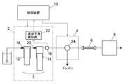
- the liquid chromatograph includes a liquid feeding system 2, a sample injection unit 4, a separation column 6, a detector 8, and a control device 10.
- the liquid feeding system 2 of this embodiment is a series type double plunger type liquid feeding mechanism including two plunger pumps 12 (first plunger pump) and a plunger pump 14 (second plunger pump) connected in series with each other. 3 and a pressure sensor 16 for detecting the liquid feeding pressure by the liquid feeding mechanism 3 are provided.
- a check valve 18 is provided at the inlet of the plunger pump 12 on the front stage side, and a check valve 20 is provided between the outlet portion of the plunger pump 12 on the front stage side and the inlet portion of the plunger pump 14 on the rear stage side. ..
- the plunger pumps 12 and 14 are configured to operate complementarily to each other to stably deliver liquid. Specifically, the plunger pump 14 performs a suction operation while the plunger pump 12 is performing a discharge operation, and the plunger pump 14 performs a discharge operation while the plunger pump 12 is performing a suction operation.
- the liquid feed system 2 also includes a liquid feed defect detection unit 22.
- the liquid feed defect detection unit 22 is a function obtained by executing a predetermined program in an electronic circuit forming a part of the liquid feed system 2.
- the liquid feed defect detection unit 22 reads the liquid feed pressure detected by the pressure sensor 16, and due to the fluctuation of the liquid feed pressure, the liquid feed failure by the liquid feed mechanism 3, specifically, into the plunger pump 12 or 14. It is configured to detect poor liquid feeding due to the inclusion of air bubbles.
- the liquid feeding defect detection unit 22 can also be provided as a function of the control device 10. Details of detection of poor liquid transfer will be described later.
- the sample injection unit 4 is connected to the downstream of the liquid feeding mechanism 3.
- the sample injection unit 4 is for injecting a sample into the mobile phase to be fed by the liquid feeding mechanism 3.
- the sample injection unit 4 includes a switching valve 24, and by switching the switching valve 24, it is possible to switch whether the mobile phase from the liquid feeding system 2 is guided to the separation column 6 or discharged to the drain.
- the switching valve for switching whether the mobile phase from the liquid feeding system 2 is guided to the separation column 6 or discharged to the drain does not necessarily have to be provided in the sample injection unit 4, and the sample injection unit does not necessarily have to be provided. It may be provided separately from 4. Further, such a switching valve does not necessarily have to be provided for detecting a liquid feeding defect.
- the separation column 6 is connected downstream of the sample injection section 4, and the detector 8 is connected downstream of the separation column 6.
- the separation column 6 is for separating the sample injected into the mobile phase by the sample injection unit 4 for each component, and the sample component separated by the separation column 6 is detected by the detector 8.
- the control device 10 is for at least managing the operation of the liquid feeding system 2 and the sample injection unit 4, and is realized by, for example, a system controller dedicated to this liquid chromatograph and / or a general-purpose personal computer.
- the liquid feeding defect detecting unit 22 of the liquid feeding system 2 detects a liquid feeding defect of the liquid feeding mechanism including the plunger pumps 12 and 14, a signal indicating that the liquid feeding defect is detected is transmitted to the control device 10.
- the control device 10 is preset to execute the purging operation of the plunger pumps 12 and 14 for eliminating the liquid feeding failure, the switching valve 24 is moved to the drain side with respect to the sample injection unit 4.
- a command is sent to switch, and a command is sent to the liquid feeding system 2 to increase the liquid feeding flow rate to a predetermined high flow rate. As a result, the air bubbles in the plunger pumps 12 and 14 are discharged to the drain.
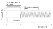
- the liquid transfer pressure is stable, although slight pressure fluctuations due to the operation of the plunger pumps 12 and 14 are observed, as shown in the left side portion of the pressure waveform in FIG. ing. If air bubbles are mixed in any of the plunger pumps 12 or 14, the liquid is not discharged normally due to the compression of the generated air bubbles during the discharge operation of one of the plunger pumps 12 or 14 in which the air bubbles are mixed, so that the liquid feeding pressure is increased. It descends sharply. When the other plunger pump 14 or 12 is discharged, the liquid is discharged normally, so that the liquid feeding pressure rises. As a result, as shown on the right side of the pressure waveform in FIG. 2, fluctuations (pulsation) in the liquid feeding pressure occur in synchronization with the drive cycle of the liquid feeding mechanism 3. Therefore, the liquid feeding defect detecting unit 22 is configured to detect the liquid feeding defect by detecting the pulsation.
- the cycle of pulsation caused by the mixing of air bubbles into the plunger pump 12 or 14 is synchronized with the drive cycle of the liquid feeding mechanism 3 including the plunger pump 12 or 14. Therefore, in order to detect the pulsation, it is necessary to capture the signal of the pressure sensor 16 at such a frequency that the fluctuation of the liquid feeding pressure within one drive cycle of the liquid feeding mechanism 3 can be read. Therefore, the frequency with which the liquid feeding defect detecting unit 22 takes in the signal from the pressure sensor 16 may be adjusted according to the driving speed of the plunger pump 12 or 14. In that case, the cycle of reading the signal from the pressure sensor 16 can be determined by calculation when the liquid feed flow rate is determined.
- the example of FIG. 3 is effective when the fluctuation of the liquid feeding pressure within one drive cycle of the liquid feeding mechanism 3 can be read in several tens of divisions.
- the liquid feed pressure can be read at such a high frequency
- the liquid feed pressure at the start and end points of the discharge operation of the plunger pump 12 and the liquid feed pressure at the start and end points of the discharge operation of the plunger pump 14 are determined. Can be read accurately.
- one cycle of driving the liquid feeding mechanism 3 means the other plunger of the plunger pumps 12 and 14 from the time when the discharge operation of the plunger pump 12 or 14 of the plunger pumps 12 and 14 starts. It means until the time when the discharge operation of the pump 14 or 12 is completed.
- the liquid feeding defect detection unit 22 takes in the signal of the pressure sensor 16 at a predetermined frequency and reads the liquid feeding pressure (moving average value).
- the liquid feed defect detection unit 22 reads the liquid feed pressure at the start point and the end point of the discharge operation of one of the plunger pumps 12 and 14, the plunger pump 12 or 14, the difference between them (feed of the start point).
- Liquid pressure-liquid feeding pressure at the end point) is obtained as the first fluctuation value (step 101)
- the difference between them (the liquid feeding pressure at the start point-the liquid feeding pressure at the ending point) is obtained as the second fluctuation value (step 102).
- the liquid feeding pressure drops during the discharge operation of the one plunger pump 12 or 14 in which air bubbles are mixed, and the air bubbles are mixed. Since the liquid feed pressure rises during the discharge operation of the other plunger pump 14 or 12, if the liquid feed failure caused by the mixing of air bubbles occurs in the liquid feed mechanism 3, the first Only one of the fluctuation value and the second fluctuation value is a positive value (the other is a negative value). Therefore, when the signs of the first fluctuation value and the second fluctuation value are the same, it can be determined that the pulsation is not caused by the mixing of bubbles (step 103).
- the liquid feed defect detection unit 22 uses the first fluctuation value and the second fluctuation value to perform one drive cycle of the liquid feed mechanism 3.
- the fluctuation range of the liquid feeding pressure in the inside is obtained (step 104).
- Or fluctuation range (first fluctuation value-second fluctuation value) 2
- the fluctuation range may be obtained by using an equation such as.
- the liquid feed defect detection unit 22 compares the above fluctuation value with a predetermined reference value, and when the fluctuation value exceeds the reference value, the drive cycle (fluctuation cycle) in which the fluctuation value exceeds the reference value. Count the number of consecutive times. Then, when the number of continuous fluctuation cycles reaches a predetermined reference number, the pulsation is detected (steps 106 and 107). When the pulsation is detected, the liquid feeding defect detecting unit 22 detects the liquid feeding failure by the liquid feeding mechanism 3 (step 108) and sends a warning signal to the control device 10 (step 109).
- the fluctuation range ⁇ P of the liquid feeding pressure caused by the bubbles mixed in the plunger pump 12 or 14 is determined by the time constant ⁇ of the liquid chromatograph, and the time constant ⁇ is the total liquid feeding pressure P [MPa] and the damper C. It is a value that depends on [uL / MPa] and the liquid feed flow rate Q [mL / min].
- the damper C [uL / MPa] is a value that depends on the internal capacitance V [uL] of each module or pipe constituting the liquid chromatograph and the compressibility ⁇ [GPa -1 ] of the mobile phase.
- the reference value for detecting the pulsation caused by the mixing of air bubbles in the plunger pump 12 or 14 can be determined by calculation in consideration of ⁇ P obtained by the above equation.
- the liquid feed defect detection unit 22 can calculate a reference value using the above algorithm every time the liquid feed pressure is read and use it for detecting pulsation.
- the reference value may be determined more simply by omitting some of the arguments P, C, Q, t (or P, V, ⁇ , Q, t) in the above equation.
- ⁇ P obtained with only P and C as arguments and other elements as fixed values may be used as a reference.
- the reference value does not necessarily have to be determined by calculation, and may be a preset fixed value.
- the reference number of consecutive fluctuation cycles for determining pulsation may be configured to be variably adjustable. Then, the reference number of times can be adjusted depending on how sensitive the pulsation detection is.
- the algorithm for detecting pulsation is not limited to the above.
- the liquid feeding pressure of the liquid feeding mechanism 3 for each driving cycle is monitored, the fluctuation range of the liquid feeding pressure within one driving cycle is obtained, and the fluctuation range is compared with the reference value determined as described above. Allows the detection of pulsation.
- the above algorithm is effective when it is not possible to accurately read the liquid feed pressure at the start point and end point of the discharge operation of the plunger pumps 12 and 14.
- this algorithm since it is not possible to determine whether or not the liquid feeding pressure has dropped or increased within one drive cycle of the liquid feeding mechanism 3, is it a pressure fluctuation due to the mixing of air bubbles in one of the plunger pumps 12 or 14. I can't say whether or not. Therefore, before executing the pulsation detection algorithm, a trigger detection algorithm as described in the flowchart of FIG. 4 may be introduced.
- the liquid feeding defect detection unit 22 reads the signal of the pressure sensor 16 at a predetermined cycle (step 201) and calculates the liquid feeding pressure (moving average value) (step 202). ..
- the liquid feed defect detection unit 22 calculates the drop width of the liquid feed pressure per time (for example, for 10 signal readings) set based on the drive cycle of the liquid feed mechanism 3 (step 203). Then, the calculated descent width is compared with a predetermined reference value (step 204), and when the descent width exceeds the reference value, it is detected as a trigger for pulsation generation (step 205).
- the liquid feeding failure detection unit 22 detects the pulsation by using the above-mentioned pulsation detection algorithm (step 206). When pulsation is detected, poor liquid feeding is detected (steps 207 and 208), and a warning signal is transmitted to the control device 10 (step 209). If no pulsation is detected, the process returns to step 201 (step 207).
- the coefficient for determining the reading cycle of the signal from the pressure sensor 16 and the reference value for pulsation detection by calculation is the result of the input of the change instruction by the user or the detection of the actual liquid feeding failure. It may be configured to be variably adjusted based on the user's evaluation of.
- the liquid chromatograph analysis system is connected to a database common to other liquid chromatograph analysis systems via a network line such as an internet line, the user's evaluation of the detection result of liquid transfer failure accumulated in the database.
- the reading cycle and the coefficient for determining the reference value may be automatically adjusted based on the above.
- the liquid feeding system 2 provided with the series-type double plunger type liquid feeding mechanism 3 has been described as an example, but the present invention is not limited to this, and air bubbles are mixed.
- a liquid feeding mechanism in which pressure fluctuations occur in synchronization with the drive cycle of the plunger pump that is, a liquid feeding system equipped with a parallel double plunger type liquid feeding mechanism or a single plunger type liquid feeding mechanism.
- the embodiment of the liquid feeding system according to the present invention is as follows.
- An embodiment of the liquid feeding system includes a liquid feeding mechanism configured to continuously feed liquid by at least one plunger pump that feeds liquid by reciprocating the plunger, and the liquid feeding mechanism.
- the pressure sensor for detecting the liquid feeding pressure by the mechanism and the liquid feeding pressure detected by the pressure sensor are taken in at a cycle in which the fluctuation within one drive cycle of the liquid feeding mechanism can be read, and the taken-in liquid feeding pressure is taken in.
- a liquid chromatograph liquid feeding system including a liquid feeding defect detecting unit configured to detect a liquid feeding defect of the liquid feeding mechanism by using the liquid feeding defect detecting unit.
- the fluctuation range of the liquid feeding pressure within the constant drive cycle of the mechanism is obtained, and the pulsation is detected on condition that the number of consecutive cycles in which the fluctuation width exceeds the predetermined reference value exceeds the predetermined reference number.
- the detection step and the liquid feeding defect detection step for detecting the liquid feeding defect of the liquid feeding mechanism when the pulsation is detected in the pulsation detecting step are executed in this order.
- the liquid feeding mechanism includes a first plunger pump and a second plunger pump that are driven complementarily, and the liquid feeding defect detection unit.
- the difference between the liquid feeding pressure at the start point and the end point of the discharge operation of the first plunger pump is obtained as the first fluctuation value
- the start point of the discharge operation of the second plunger pump is obtained as the second fluctuation value
- the fluctuation range is obtained by using the first fluctuation value and the second fluctuation value.
- the liquid feeding defect detection unit determines only the period in which only one of the first fluctuation value and the second fluctuation value is a positive value. It may be configured to count as a cycle exceeding the reference value of. Then, the pulsation caused by the mixing of air bubbles into the first plunger pump or the second plunger pump can be accurately detected.
- the reference number of times is variable. By making the reference number variable, it becomes possible to adjust the detection sensitivity of pulsation.
- the second aspect can be combined with the first aspect.
- the liquid feeding defect detecting unit calculates the reference value based on at least the liquid feeding pressure before the pulsation detection step. It is configured to perform a decision step. According to such an aspect, pulsation can be detected with higher accuracy.
- This third aspect can be combined with the first aspect and / or the second aspect described above.
- the coefficient used for calculating the reference value in the reference value determination step may be variable. Then, it becomes possible to adjust the reference value for detecting pulsation to a more suitable value.
- the liquid feeding defect detecting unit feeds per time set based on the driving cycle of the liquid feeding mechanism before the pulsation detection step.
- a pressure drop calculation step for calculating the drop width of the liquid pressure and a trigger detection step for detecting as a trigger for pulsation generation when the drop width calculated in the pressure drop calculation step exceeds a predetermined reference value are to be executed. It is configured to execute the pulsation determination step after detecting the trigger in the trigger detection step. Due to such an embodiment, even when the fluctuation of the liquid feeding pressure within one drive cycle of the liquid feeding mechanism cannot be read in detail, air bubbles may be mixed into the first plunger pump or the second plunger pump. The resulting pulsation can be detected accurately.
- This fourth aspect can be freely combined with a part or all of the first to third aspects.
- the cycle in which the liquid feeding defect detecting unit takes in the liquid feeding pressure from the pressure sensor is variable.
- Liquid feed system 4 Liquid feed system 4 Sample injection unit 6 Separation column 8 Detector 10 Controller 10 Control device 12, 14 Plunger pump 16 Pressure sensor 18, 20 Check valve 22 Liquid feed failure detector 24 Switching valve
Landscapes
- Physics & Mathematics (AREA)
- Health & Medical Sciences (AREA)
- Life Sciences & Earth Sciences (AREA)
- Chemical & Material Sciences (AREA)
- Analytical Chemistry (AREA)
- Biochemistry (AREA)
- General Health & Medical Sciences (AREA)
- General Physics & Mathematics (AREA)
- Immunology (AREA)
- Pathology (AREA)
- Control Of Positive-Displacement Pumps (AREA)
Abstract
送液システム(2)は、プランジャを往復駆動することにより送液を行なう少なくとも1つのプランジャポンプ(12;14)によって液を連続的に送液するように構成された送液機構(3)と、前記送液機構(3)による送液圧力を検出するための圧力センサ(16)と、前記圧力センサ(16)により検出される送液圧力を前記送液機構(3)の1駆動周期内の変動が読み取れるような周期で取り込み、取り込んだ送液圧力を用いて前記送液機構(3)の送液不良を検出するように構成された送液不良検知部(22)と、を備えた液体クロマトグラフ用送液システム(2)であって、前記送液不良検知部(22)は、前記送液機構(3)の一定駆動周期内の前記送液圧力の変動幅を求め、前記変動幅が所定の基準値を超えている周期の連続数が所定の基準回数を超えたことを条件として脈動を検出する脈動検出ステップと、前記脈動検出ステップで前記脈動を検出したときに、前記送液機構(3)の送液不良を検知する送液不良検知ステップと、をその順に実行するように構成されている。
Description
本発明は、液体クロマトグラフ分析システムにおいて移動相を連続的に送液するための送液システムに関するものである。
液体クロマトグラフ用の送液システムには、設定された流量で移動相となる溶媒を安定して送液する性能が求められている。送液システムの送液機構として、単一のプランジャポンプを備えたシングルプランジャ方式、2つのプランジャポンプを備えたダブルプランジャ方式の機構が採用されている。
プランジャポンプが溶媒を吐出する際、溶媒の圧縮、逆止弁からの液漏れ、流路への微細な気泡の混入、溶媒の枯渇などによって送液圧力が低下することで、所謂、脈動と呼ばれる送液圧力の周期的な大きな変動が発生することがある。脈動が発生すると、移動相の流量が乱れて分析結果に悪影響を与え、ユーザの損失となる。そのため、プランジャポンプの動作を制御することによって脈動を抑制したり(特許文献1参照)、脱気ユニットを使用することによって気泡を除去したり、分析を開始する前に溶媒を高流量で送液することによって流路内の気泡を外部へ排出したりするなどの対策が採られている。
上記のような対策を施したとしても、例えば、溶媒の中に残存した気体成分がプランジャポンプ内で気泡となったり、溶媒中の溶存酸素が温度変化によって飽和して気泡が発生したりするなどの理由により、送液中のプランジャポンプ内に気泡が混入し、そのまま分析が継続されてしまう場合があった。そのような場合、ユーザは無駄な分析データを取り続けることになる。
本発明は上記問題に鑑みてなされたものであり、送液中の気泡の発生に起因する送液不良を検知する機能を備えた送液システムを提供することを目的とするものである。
本発明に係る送液システムは、プランジャを往復駆動することにより送液を行なう少なくとも1つのプランジャポンプによって液を連続的に送液するように構成された送液機構と、前記送液機構による送液圧力を検出するための圧力センサと、前記圧力センサにより検出される送液圧力を前記送液機構の1駆動周期内の変動が読み取れるような周期で取り込み、取り込んだ送液圧力を用いて前記送液機構の送液不良を検出するように構成された送液不良検知部と、を備えた液体クロマトグラフ用送液システムであって、前記送液機構の一定駆動周期内の前記送液圧力の変動幅を求め、前記変動幅が所定の基準値を超えている周期の連続数が所定の基準回数を超えたことを条件として脈動を検出する脈動検出ステップと、前記脈動検出ステップで前記脈動を検出したときに、前記送液機構の送液不良を検知する送液不良検知ステップと、をその順に実行するように構成されている。
ここで、本発明において、「前記送液機構の一定駆動周期内の前記送液圧力の変動幅」とは、前記送液機構の1駆動周期内の前記送液圧力の変動幅であってもよいが、前記送液機構の複数駆動周期内の前記送液圧力の変動幅、又は前記送液機構の複数駆動周期内の前記送液圧力の変動幅の平均値であってもよい。
プランジャポンプ内に気泡が混入すると、混入した気泡の圧縮が完了するまでは液の吐出がなされないために送液圧力が急激に降下し、気泡の圧縮が完了した後は送液圧力が上昇するため、プランジャポンプの駆動と同期するような送液圧力の変動が周期的に発生するためである。したがって、プランジャポンプ内に気泡が混入したか否かは、プランジャポンプの駆動周期と同期した送液圧力の変動の有無によって検知することができる。
本発明に係る送液システムでは、送液機構の一定駆動周期内の送液圧力の変動幅を求め、変動幅が所定の基準値を超えている周期の連続数が所定の基準回数を超えたことを条件として脈動を検出し、脈動を検出したときに送液機構の送液不良を検知するように構成されているので、送液中の気泡の発生に起因する送液不良を検知する機能を備えた送液システムが提供される。
以下、本発明に係る送液システムの一実施例について、図面を参照しながら説明する。
図1に示されているように、液体クロマトグラフは、送液システム2、試料注入部4、分離カラム6、検出器8及び制御装置10を備えている。
この実施例の送液システム2は、互いに直列に接続された2つのプランジャポンプ12(第1のプランジャポンプ)、プランジャポンプ14(第2のプランジャポンプ)からなる直列型ダブルプランジャ方式の送液機構3と、その送液機構3による送液圧力を検出するための圧力センサ16を備えている。前段側のプランジャポンプ12の入口部に逆止弁18が設けられ、前段側のプランジャポンプ12の出口部と後段側のプランジャポンプ14の入口部との間に逆止弁20が設けられている。プランジャポンプ12と14は互いに相補的に動作して安定的に送液するように構成されている。具体的には、プランジャポンプ12が吐出動作を行なっている間はプランジャポンプ14が吸入動作を行ない、プランジャポンプ12が吸入動作を行なっている間にプランジャポンプ14が吐出動作を行なう。
送液システム2はまた、送液不良検知部22を備えている。送液不良検知部22は、送液システム2の一部を構成する電子回路において所定のプログラムが実行されることによって得られる機能である。送液不良検知部22は、圧力センサ16によって検出される送液圧力を読み取り、その送液圧力の変動によって送液機構3による送液不良、具体的には、プランジャポンプ12又は14内への気泡の混入に起因する送液不良を検知するように構成されている。なお、送液不良検知部22は、制御装置10の機能として設けることもできる。送液不良の検知の詳細については後述する。
試料注入部4は送液機構3の下流に接続されている。試料注入部4は送液機構3によって送液される移動相中に試料を注入するためのものである。この実施例では、試料注入部4は切替バルブ24を備えており、切替バルブ24の切替えによって送液システム2からの移動相を分離カラム6へ導くか、又は、ドレインへ排出するかを切り替えることができるように構成されている。なお、送液システム2からの移動相を分離カラム6へ導くか、又は、ドレインへ排出するかを切り替えるための切替バルブは、必ずしも試料注入部4に設けられている必要はなく、試料注入部4とは別に設けられていてもよい。また、送液不良の検知のためには、必ずしもそのような切替バルブが設けられていなくてもよい。
分離カラム6は試料注入部4の下流に接続され、検出器8は分離カラム6の下流に接続されている。分離カラム6は、試料注入部4によって移動相中に注入された試料を成分ごとに分離するためのものであり、分離カラム6で分離された試料成分が検出器8により検出される。
制御装置10は、少なくとも送液システム2及び試料注入部4の動作管理を行なうためのものであり、例えばこの液体クロマトグラフ専用のシステムコントローラ及び/又は汎用のパーソナルコンピュータによって実現されるものである。送液システム2の送液不良検知部22がプランジャポンプ12、14からなる送液機構の送液不良を検知した場合、送液不良を検知したことを示す信号が制御装置10へ送信される。その場合、制御装置10は、送液不良を解消するためのプランジャポンプ12及び14のパージ動作を実行するように予め設定されているときには、試料注入部4に対して切替バルブ24をドレイン側へ切り替えるように指令を送信し、送液システム2に対して送液流量を所定の高流量まで上昇させるように指令を送信する。これにより、プランジャポンプ12及び14内の気泡がドレインへ排出される。
ここで、プランジャポンプ12又は14内に気泡が混入したときの送液圧力の変動について、図2を用いて説明する。
移動相を安定的に送液できる状態では、図2の圧力波形の左側部分のように、送液圧力は、プランジャポンプ12及び14の動作等に起因した僅かな圧力変動はみられるものの安定している。いずれかのプランジャポンプ12又は14内に気泡が混入すると、気泡が混入した一方のプランジャポンプ12又は14の吐出動作の際に、発生した気泡の圧縮により液が正常に吐出されないため送液圧力が急激に降下する。他方のプランジャポンプ14又は12の吐出動作の際には液の吐出が正常になされるため送液圧力が上昇する。その結果、図2の圧力波形の右側部分のように、送液機構3の駆動周期と同期するような送液圧力の変動(脈動)が発生する。したがって、送液不良検知部22は、脈動を検出することによって送液不良を検知するように構成されている。
ここで、プランジャポンプ12又は14内への気泡の混入に起因する脈動の周期は、プランジャポンプ12又は14からなる送液機構3の駆動周期と同期する。そのため、脈動を検出するためには、送液機構3の1駆動周期内における送液圧力の変動を読み取ることができるような頻度で圧力センサ16の信号を取り込む必要がある。そのため、送液不良検知部22が圧力センサ16から信号を取り込む頻度は、プランジャポンプ12又は14の駆動速度に応じて調整されるようになっていてもよい。その場合、圧力センサ16から信号を読み込む周期は、送液流量が決定されたときに計算によって決定することができる。
送液不良検知部22による脈動検出のアルゴリズムの一例について、図3のフローチャートを用いて説明する。
図3の例は、送液機構3の1駆動周期内の送液圧力の変動を数十分割で読み取ることができる場合に有効である。そのような高頻度で送液圧力を読み取ることができる場合、プランジャポンプ12の吐出動作の開始点と終了点における送液圧力、プランジャポンプ14の吐出動作の開始点と終了点における送液圧力を正確に読み取ることができる。ここで、送液機構3の駆動の1周期とは、プランジャポンプ12及び14のうちの一方のプランジャポンプ12又は14の吐出動作が開始した時点から、プランジャポンプ12及び14のうちの他方のプランジャポンプ14又は12の吐出動作が終了した時点までをいう。
送液機構3が送液を開始すると、送液不良検知部22は、圧力センサ16の信号を所定の頻度で取り込んで送液圧力(移動平均値)を読み取る。送液不良検知部22は、プランジャポンプ12及び14のうちの一方のプランジャポンプ12又は14の吐出動作の開始点と終了点における送液圧力を読み取ったときに、それらの差分(開始点の送液圧力-終了点の送液圧力)を第1変動値として求め(ステップ101)、プランジャポンプ12及び14のうちの他方のプランジャポンプ14又は12の吐出動作の開始点と終了点における送液圧力を読み取ったときに、それらの差分(開始点の送液圧力-終了点の送液圧力)を第2変動値として求める(ステップ102)。いずれか一方のプランジャポンプ12又は14で気泡の混入が発生している場合、気泡の混入が発生している一方のプランジャポンプ12又は14の吐出動作中に送液圧力が降下し、気泡の混入が発生していない他方のプランジャポンプ14又は12の吐出動作中に送液圧力が上昇するため、送液機構3において気泡の混入に起因した送液不良が発生しているのであれば、第1変動値と第2変動値のいずれか一方のみが正の値(他方は負の値)となる。したがって、第1変動値と第2変動値の符号が同じである場合には、気泡の混入に起因した脈動ではないと判定することができる(ステップ103)。
第1変動値と第2変動値のいずれか一方のみが正の値である場合、送液不良検知部22は、第1変動値と第2変動値を用いて送液機構3の1駆動周期内における送液圧力の変動幅を求める(ステップ104)。送液圧力の変動幅は、例えば次式により求めることができる。
変動幅=|第1変動値-第2変動値|/2
なお、上記式は一例であり、
変動幅=|第1変動値-第2変動値|
又は
変動幅=(第1変動値-第2変動値)2
などの式を用いて変動幅を求めてもよい。
変動幅=|第1変動値-第2変動値|/2
なお、上記式は一例であり、
変動幅=|第1変動値-第2変動値|
又は
変動幅=(第1変動値-第2変動値)2
などの式を用いて変動幅を求めてもよい。
送液不良検知部22は、上記の変動値を所定の基準値と比較し、変動値が基準値を超えている場合には、変動値が基準値を超えている駆動周期(変動周期)の連続数をカウントする。そして、変動周期の連続数が所定の基準回数に達したときに、脈動を検出する(ステップ106、107)。脈動を検出すると、送液不良検知部22は、送液機構3による送液不良を検知し(ステップ108)、制御装置10へ警告信号を発信する(ステップ109)。
ここで、プランジャポンプ12又は14に混入した気泡に起因する送液圧力の変動幅ΔPは、液体クロマトグラフの時定数τによって決まり、時定数τは全体の送液圧力P[MPa]、ダンパC[uL/MPa]、送液流量Q[mL/min]に依存する値である。ダンパ C[uL/MPa]は、液体クロマトグラフを構成する各モジュールや配管の内部容量V[uL]と移動相の圧縮率β[GPa-1]に依存する値である。例えば、プランジャポンプ12又は14へ気泡が混入した後の経過時間をt秒とすると、送液圧力の変動幅ΔPは、
 によって決定されると考えられる。したがって、プランジャポンプ12又は14への気泡の混入に起因した脈動を検出するための基準値は、上記式によって求められるΔPを考慮して計算により決定することができる。
送液不良検知部22は、送液圧力を読み取る度に、上記アルゴリズムを用いて基準値を計算し、脈動の検出に用いることができる。ただし、上記式の引数P、C、Q、t(又は、P、V、β、Q、t)のうちのいくつかを省略してより簡略的に基準値を決定してもよい。例えば、P、Cのみを引数として他の要素を固定値として求められるΔPを基準としてもよい。なお、基準値は、必ずしも計算によって決定する必要はなく、予め設定された固定値としてもよい。
また、脈動と判定するための変動周期の連続数の基準回数は、可変に調整できるように構成されていてもよい。そうすれば、脈動検知の感度をどの程度にするかによって基準回数を調整することができる。
なお、脈動を検出するためのアルゴリズムは上記のものに限定されない。例えば、送液機構3の1駆動周期ごとの送液圧力を監視し、1駆動周期内における送液圧力の変動幅を求め、その変動幅を上記のように決定された基準値と比較することによって、脈動の検出を行なうことができる。
上記のアルゴリズムは、プランジャポンプ12及び14の吐出動作の開始点及び終点における送液圧力を正確に読み取ることができないような場合に有効である。ただし、このアルゴリズムでは、送液機構3の1駆動周期内に送液圧力の降下と上昇があったか否かを判別できないため、一方のプランジャポンプ12又は14への気泡の混入による圧力変動であるか否かを断定できない。そこで、脈動の検出のアルゴリズムを実行する前に、図4のフローチャートに説明するようなトリガーの検出のアルゴリズムを導入してもよい。
送液機構3による送液を開始すると、送液不良検知部22は、圧力センサ16の信号を所定の周期で読み込み(ステップ201)、送液圧力(移動平均値)を算出する(ステップ202)。送液不良検知部22は、送液機構3の駆動周期に基づいて設定された時間当たり(例えば信号読込み10回分)の送液圧力の降下幅を算出する(ステップ203)。そして、算出した降下幅を所定の基準値と比較し(ステップ204)、降下幅が基準値を超えたときに脈動発生のトリガーとして検出する(ステップ205)。
送液不良検知部22は、トリガーを検知した後、上述の脈動検出のアルゴリズムを用いて脈動の検出を行なう(ステップ206)。脈動が検出された場合は、送液不良を検知すし(ステップ207、208)、警告信号を制御装置10へ送信する(ステップ209)。脈動が検出されなかった場合は、上記ステップ201へ戻る(ステップ207)。
ここで、圧力センサ16からの信号の読込み周期、脈動検出のための基準値をそれぞれ計算により決定するための係数は、ユーザによる変更指示の入力によって、又は、実際の送液不良の検知の結果に対するユーザの評価に基づいて、可変に調整されるように構成されていてもよい。また、液体クロマトグラフの分析システムがインターネット回線などのネットワーク回線を通じて他の液体クロマトグラフの分析システムと共通のデータベースに接続されている場合、データベースに蓄積されたユーザによる送液不良の検知結果に対する評価に基づいて読込み周期や基準値を決定するための係数が自動的に調整されるように構成されていてもよい。
以上において説明した実施例では、直列型のダブルプランジャ方式の送液機構3を備えた送液システム2を例に挙げて説明したが、本発明はこれに限定されるものではなく、気泡の混入によってプランジャポンプの駆動周期に同期した圧力変動が発生する送液機構、すなわち、並列型のダブルプランジャ方式の送液機構やシングルプランジャ方式の送液機構を備えた送液システムに対しても同様に適用することができる。すなわち、上記実施例は本発明に係る送液システムの実施形態の一例を示したに過ぎない。本発明に係る送液システムの実施形態は以下のとおりである。
本発明に係る送液システムの実施形態は、プランジャを往復駆動することにより送液を行なう少なくとも1つのプランジャポンプによって液を連続的に送液するように構成された送液機構と、前記送液機構による送液圧力を検出するための圧力センサと、前記圧力センサにより検出される送液圧力を前記送液機構の1駆動周期内の変動が読み取れるような周期で取り込み、取り込んだ送液圧力を用いて前記送液機構の送液不良を検出するように構成された送液不良検知部と、を備えた液体クロマトグラフ用送液システムであって、前記送液不良検知部は、前記送液機構の一定駆動周期内の前記送液圧力の変動幅を求め、前記変動幅が所定の基準値を超えている周期の連続数が所定の基準回数を超えたことを条件として脈動を検出する脈動検出ステップと、前記脈動検出ステップで前記脈動を検出したときに、前記送液機構の送液不良を検知する送液不良検知ステップと、をその順に実行するように構成されている。
本発明に係る送液システムの実施形態の第1態様では、前記送液機構は、相補的に駆動される第1のプランジャポンプ及び第2のプランジャポンプを備えており、前記送液不良検知部は、前記脈動検出ステップにおいて、前記第1のプランジャポンプの吐出動作の開始点と終了点の前記送液圧力の差分を第1変動値として求め、前記第2のプランジャポンプの吐出動作の開始点と終了点の前記送液圧力の差分を第2変動値として求め、前記第1変動値と前記第2変動値を用いて前記変動幅を求めるように構成されている。
上記第1態様において、前記送液不良検知部は、前記脈動検出ステップにおいて、前記第1変動値と前記第2変動値のどちらか一方のみが正の値である周期のみを前記変動幅が所定の基準値を超えている周期としてカウントするように構成されていてもよい。そうすれば、第1のプランジャポンプ又は第2のプランジャポンプへの気泡の混入に起因した脈動を正確に検出することができる。
本発明に係る送液システムの実施形態の第2態様では、前記基準回数は可変である。前記基準回数を可変とすることで、脈動の検出感度を調節することが可能になる。なお、この第2態様は上記第1態様と組み合わせることができる。
本発明に係る送液システムの実施形態の第3態様では、前記送液不良検知部は、前記脈動検出ステップの前に、少なくとも前記送液圧力に基づいて前記基準値を計算により決定する基準値決定ステップを実行するように構成されている。このような態様により、脈動の検出をより高精度に行なうことができる。この第3態様は、上記第1態様及び/又は第2態様と組み合わせることができる。
上記第3態様において、前記基準値決定ステップにおいて前記基準値の計算に用いられる係数は可変であってよい。そうすれば、脈動の検出のための基準値をより適した値へ調整することが可能になる。
本発明に係る送液システムの実施形態の第4態様では、前記送液不良検知部は、前記脈動検出ステップの前に、前記送液機構の前記駆動周期に基づいて設定された時間当たりの送液圧力の降下幅を算出する圧力降下算出ステップと、前記圧力降下算出ステップで算出した降下幅が所定の基準値を超えたときに脈動発生のトリガーとして検出するトリガー検出ステップと、を実行するように構成され、前記トリガー検出ステップで前記トリガーを検出した後で、脈動判定ステップを実行するように構成されている。このような態様により、前記送液機構の1駆動周期内の送液圧力の変動を詳細に読み取ることができないような場合でも、第1のプランジャポンプ又は第2のプランジャポンプへの気泡の混入に起因した脈動を正確に検出することができる。この第4態様は、上記第1態様から第3態様の一部又は全部と自在に組み合わせることができる。
本発明に係る送液システムの実施形態の第5態様では、前記送液不良検知部が前記圧力センサから送液圧力を取り込む周期は可変である。
2 送液システム
4 試料注入部
6 分離カラム
8 検出器
10 制御装置
12,14 プランジャポンプ
16 圧力センサ
18,20 逆止弁
22 送液不良検知部
24 切替バルブ
4 試料注入部
6 分離カラム
8 検出器
10 制御装置
12,14 プランジャポンプ
16 圧力センサ
18,20 逆止弁
22 送液不良検知部
24 切替バルブ
Claims (8)
- プランジャを往復駆動することにより送液を行なう少なくとも1つのプランジャポンプによって液を連続的に送液するように構成された送液機構と、
前記送液機構による送液圧力を検出するための圧力センサと、
前記圧力センサにより検出される送液圧力を前記送液機構の1駆動周期内の変動が読み取れるような周期で取り込み、取り込んだ送液圧力を用いて前記送液機構の送液不良を検出するように構成された送液不良検知部と、を備えた液体クロマトグラフ用送液システムであって、
前記送液不良検知部は、
前記送液機構の一定駆動周期内の前記送液圧力の変動幅を求め、前記変動幅が所定の基準値を超えている周期の連続数が所定の基準回数を超えたことを条件として脈動を検出する脈動検出ステップと、
前記脈動検出ステップで前記脈動を検出したときに、前記送液機構の送液不良を検知する送液不良検知ステップと、をその順に実行するように構成されている、液体クロマトグラフ用送液システム。 - 前記送液機構は、相補的に駆動される第1のプランジャポンプ及び第2のプランジャポンプを備えており、
前記送液不良検知部は、前記脈動検出ステップにおいて、前記第1のプランジャポンプの吐出動作の開始点と終了点の前記送液圧力の差分を第1変動値として求め、前記第2のプランジャポンプの吐出動作の開始点と終了点の前記送液圧力の差分を第2変動値として求め、前記第1変動値と前記第2変動値を用いて前記変動幅を求めるように構成されている、請求項1に記載の液体クロマトグラフ用送液システム。 - 前記送液不良検知部は、前記脈動検出ステップにおいて、前記第1変動値と前記第2変動値のどちらか一方のみが正の値である周期のみを前記変動幅が所定の基準値を超えている周期としてカウントするように構成されている、請求項2に記載の液体クロマトグラフ用送液システム。
- 前記基準回数は可変である、請求項1に記載の液体クロマトグラフ用送液システム。
- 前記送液不良検知部は、前記脈動検出ステップの前に、少なくとも前記送液圧力に基づいて前記基準値を計算により決定する基準値決定ステップを実行するように構成されている、請求項1に記載の液体クロマトグラフ用送液システム。
- 前記基準値決定ステップにおいて前記基準値の計算に用いられる係数は可変である、請求項5に記載の液体クロマトグラフ用送液システム。
- 前記送液不良検知部は、前記脈動検出ステップの前に、
前記送液機構の前記駆動周期に基づいて設定された時間当たりの送液圧力の降下幅を算出する圧力降下算出ステップと、
前記圧力降下算出ステップで算出した降下幅が所定の基準値を超えたときに脈動発生のトリガーとして検出するトリガー検出ステップと、を実行するように構成され、
前記トリガー検出ステップで前記トリガーを検出した後で、脈動判定ステップを実行するように構成されている、請求項1に記載の液体クロマトグラフ用送液システム。 - 前記送液不良検知部が前記圧力センサから送液圧力を取り込む周期は可変である、請求項1に記載の液体クロマトグラフ用送液システム。
Priority Applications (3)
| Application Number | Priority Date | Filing Date | Title |
|---|---|---|---|
| JP2021505495A JP7226525B2 (ja) | 2019-03-13 | 2019-10-16 | 液体クロマトグラフ用送液システム |
| CN201980093794.1A CN113544505B (zh) | 2019-03-13 | 2019-10-16 | 液相色谱仪用送液系统 |
| US17/438,421 US12105069B2 (en) | 2019-03-13 | 2019-10-16 | Liquid sending system for liquid chromatograph |
Applications Claiming Priority (2)
| Application Number | Priority Date | Filing Date | Title |
|---|---|---|---|
| JP2019045544 | 2019-03-13 | ||
| JP2019-045544 | 2019-03-13 |
Publications (1)
| Publication Number | Publication Date |
|---|---|
| WO2020183774A1 true WO2020183774A1 (ja) | 2020-09-17 |
Family
ID=72427425
Family Applications (1)
| Application Number | Title | Priority Date | Filing Date |
|---|---|---|---|
| PCT/JP2019/040649 Ceased WO2020183774A1 (ja) | 2019-03-13 | 2019-10-16 | 液体クロマトグラフ用送液システム |
Country Status (4)
| Country | Link |
|---|---|
| US (1) | US12105069B2 (ja) |
| JP (1) | JP7226525B2 (ja) |
| CN (1) | CN113544505B (ja) |
| WO (1) | WO2020183774A1 (ja) |
Cited By (5)
| Publication number | Priority date | Publication date | Assignee | Title |
|---|---|---|---|---|
| US20230091683A1 (en) * | 2020-03-24 | 2023-03-23 | Hitachi High-Tech Corporation | Liquid feeding apparatus and liquid feeding method |
| JPWO2023218758A1 (ja) * | 2022-05-12 | 2023-11-16 | ||
| JPWO2024080246A1 (ja) * | 2022-10-14 | 2024-04-18 | ||
| WO2025033015A1 (ja) | 2023-08-07 | 2025-02-13 | 株式会社日立ハイテク | 故障個所推定方法、及び液体クロマトグラフ |
| US12546674B2 (en) | 2022-09-14 | 2026-02-10 | Shimadzu Corporation | Pressure sensor with non-metallic block and non-metallic diaphragm |
Families Citing this family (2)
| Publication number | Priority date | Publication date | Assignee | Title |
|---|---|---|---|---|
| JP2025068331A (ja) * | 2023-10-16 | 2025-04-28 | 株式会社島津製作所 | 送液異常診断方法及び液体クロマトグラフ |
| CN121878096B (zh) * | 2026-03-20 | 2026-05-26 | 杭州海康威视元物智科技有限公司 | 一种液相色谱仪故障诊断方法、液相色谱仪、装置及设备 |
Citations (4)
| Publication number | Priority date | Publication date | Assignee | Title |
|---|---|---|---|---|
| JPS6011690A (ja) * | 1983-06-30 | 1985-01-21 | Shimadzu Corp | 液体クロマトグラフ |
| JP2000130353A (ja) * | 1998-10-30 | 2000-05-12 | Shimadzu Corp | 送液ポンプ |
| US20160327514A1 (en) * | 2015-05-08 | 2016-11-10 | Agilent Technologies, Inc. | Correcting sample metering inaccuracy due to thermally induced volume change in sample separation apparatus |
| WO2017090184A1 (ja) * | 2015-11-27 | 2017-06-01 | 株式会社島津製作所 | 送液装置 |
Family Cites Families (16)
| Publication number | Priority date | Publication date | Assignee | Title |
|---|---|---|---|---|
| JPS5910064U (ja) | 1982-06-29 | 1984-01-21 | 株式会社島津製作所 | 液体クロマトグラフの送液装置 |
| CA1186166A (en) | 1982-02-27 | 1985-04-30 | Katsuhiko Saito | Liquid chromatograph |
| JP2556039B2 (ja) * | 1986-06-19 | 1996-11-20 | 株式会社島津製作所 | 送液ポンプ |
| JPH07218488A (ja) * | 1994-01-31 | 1995-08-18 | Tosoh Corp | 液体クロマトグラフ用送液装置 |
| JPH11326300A (ja) * | 1998-05-20 | 1999-11-26 | Shimadzu Corp | 液体クロマトグラフ |
| JP4092831B2 (ja) | 1999-11-24 | 2008-05-28 | 株式会社島津製作所 | 送液装置 |
| US6635173B2 (en) | 2000-12-28 | 2003-10-21 | Cohesive Technologies, Inc. | Multi column chromatography system |
| US7241115B2 (en) | 2002-03-01 | 2007-07-10 | Waters Investments Limited | Methods and apparatus for determining the presence or absence of a fluid leak |
| US7674375B2 (en) | 2004-05-21 | 2010-03-09 | Waters Technologies Corporation | Closed loop flow control of a HPLC constant flow pump to enable low-flow operation |
| JP2006118374A (ja) * | 2004-10-19 | 2006-05-11 | Hitachi High-Technologies Corp | 送液システム |
| WO2011001536A1 (ja) * | 2009-06-29 | 2011-01-06 | 本多電子株式会社 | 液体圧送設備の異常検出装置及び方法、異常検出機能付きの超音波流量計 |
| JP5624825B2 (ja) * | 2010-07-29 | 2014-11-12 | 株式会社日立ハイテクノロジーズ | 液体クロマトグラフ用ポンプ、および液体クロマトグラフ |
| US10054569B2 (en) * | 2010-10-29 | 2018-08-21 | Thermo Finnigan Llc | Method and system for liquid chromatography fluidic monitoring |
| US9243619B2 (en) | 2011-09-13 | 2016-01-26 | Seiko Epson Corporation | Liquid feed pump and circulation pump with detection units to detect operating states of the pumps |
| WO2015008845A1 (ja) | 2013-07-17 | 2015-01-22 | 積水メディカル株式会社 | 試料分析装置におけるグラジエント送液装置 |
| US10995740B2 (en) | 2016-09-26 | 2021-05-04 | Shimadzu Corporation | Switching valve, binary pump, and liquid chromatograph with binary pump |
-
2019
- 2019-10-16 US US17/438,421 patent/US12105069B2/en active Active
- 2019-10-16 JP JP2021505495A patent/JP7226525B2/ja active Active
- 2019-10-16 WO PCT/JP2019/040649 patent/WO2020183774A1/ja not_active Ceased
- 2019-10-16 CN CN201980093794.1A patent/CN113544505B/zh active Active
Patent Citations (4)
| Publication number | Priority date | Publication date | Assignee | Title |
|---|---|---|---|---|
| JPS6011690A (ja) * | 1983-06-30 | 1985-01-21 | Shimadzu Corp | 液体クロマトグラフ |
| JP2000130353A (ja) * | 1998-10-30 | 2000-05-12 | Shimadzu Corp | 送液ポンプ |
| US20160327514A1 (en) * | 2015-05-08 | 2016-11-10 | Agilent Technologies, Inc. | Correcting sample metering inaccuracy due to thermally induced volume change in sample separation apparatus |
| WO2017090184A1 (ja) * | 2015-11-27 | 2017-06-01 | 株式会社島津製作所 | 送液装置 |
Cited By (9)
| Publication number | Priority date | Publication date | Assignee | Title |
|---|---|---|---|---|
| US20230091683A1 (en) * | 2020-03-24 | 2023-03-23 | Hitachi High-Tech Corporation | Liquid feeding apparatus and liquid feeding method |
| US12153026B2 (en) * | 2020-03-24 | 2024-11-26 | Hitachi High-Tech Corporation | Liquid feeding apparatus and liquid feeding method |
| JPWO2023218758A1 (ja) * | 2022-05-12 | 2023-11-16 | ||
| WO2023218758A1 (ja) * | 2022-05-12 | 2023-11-16 | 株式会社島津製作所 | クロマトグラフ用送液システムおよびクロマトグラフ用送液方法 |
| JP7754301B2 (ja) | 2022-05-12 | 2025-10-15 | 株式会社島津製作所 | クロマトグラフ用送液システムおよびクロマトグラフ用送液方法 |
| US12546674B2 (en) | 2022-09-14 | 2026-02-10 | Shimadzu Corporation | Pressure sensor with non-metallic block and non-metallic diaphragm |
| JPWO2024080246A1 (ja) * | 2022-10-14 | 2024-04-18 | ||
| WO2025033015A1 (ja) | 2023-08-07 | 2025-02-13 | 株式会社日立ハイテク | 故障個所推定方法、及び液体クロマトグラフ |
| EP4760255A1 (en) | 2023-08-07 | 2026-06-17 | Hitachi High-Tech Corporation | Defective point estimation method and liquid chromatograph |
Also Published As
| Publication number | Publication date |
|---|---|
| JPWO2020183774A1 (ja) | 2021-12-09 |
| CN113544505B (zh) | 2023-08-11 |
| JP7226525B2 (ja) | 2023-02-21 |
| US20220128533A1 (en) | 2022-04-28 |
| US12105069B2 (en) | 2024-10-01 |
| CN113544505A (zh) | 2021-10-22 |
Similar Documents
| Publication | Publication Date | Title |
|---|---|---|
| JP7226525B2 (ja) | 液体クロマトグラフ用送液システム | |
| JP7226524B2 (ja) | 液体クロマトグラフ用送液システム | |
| EP0901576B1 (en) | Bubble detection and recovery in a liquid pumping system | |
| JP5155937B2 (ja) | 送液装置および液体クロマトグラフ装置 | |
| US11098702B2 (en) | Liquid delivery device and fluid chromatograph | |
| US8551423B2 (en) | Liquid supply device using check valve and reactive liquid chromatography system | |
| CN110809713B (zh) | 送液装置及流体色谱仪 | |
| CN108026908B (zh) | 送液装置 | |
| EP1777515B1 (en) | Flow meter with a metering device and a control unit | |
| WO2019211930A1 (ja) | オートサンプラ及び液体クロマトグラフ | |
| JPWO2019008617A1 (ja) | 送液装置 | |
| JP7120438B2 (ja) | 液体クロマトグラフ | |
| WO2021005728A1 (ja) | 送液ポンプ及び液体クロマトグラフ | |
| EP1311761A1 (en) | Bubble detection and recovery in a liquid pumping system | |
| JP7226523B2 (ja) | 液体クロマトグラフ分析システム | |
| CN115398225B (zh) | 液相层析分析系统 | |
| WO2023218758A1 (ja) | クロマトグラフ用送液システムおよびクロマトグラフ用送液方法 |
Legal Events
| Date | Code | Title | Description |
|---|---|---|---|
| 121 | Ep: the epo has been informed by wipo that ep was designated in this application |
Ref document number: 19919515 Country of ref document: EP Kind code of ref document: A1 |
|
| ENP | Entry into the national phase |
Ref document number: 2021505495 Country of ref document: JP Kind code of ref document: A |
|
| NENP | Non-entry into the national phase |
Ref country code: DE |
|
| 122 | Ep: pct application non-entry in european phase |
Ref document number: 19919515 Country of ref document: EP Kind code of ref document: A1 |