WO2020183675A1 - ソレノイド - Google Patents
ソレノイド Download PDFInfo
- Publication number
- WO2020183675A1 WO2020183675A1 PCT/JP2019/010385 JP2019010385W WO2020183675A1 WO 2020183675 A1 WO2020183675 A1 WO 2020183675A1 JP 2019010385 W JP2019010385 W JP 2019010385W WO 2020183675 A1 WO2020183675 A1 WO 2020183675A1
- Authority
- WO
- WIPO (PCT)
- Prior art keywords
- solenoid
- yoke
- bobbin
- iron core
- terminal
- Prior art date
Links
Images


Classifications
-
- H—ELECTRICITY
- H01—ELECTRIC ELEMENTS
- H01F—MAGNETS; INDUCTANCES; TRANSFORMERS; SELECTION OF MATERIALS FOR THEIR MAGNETIC PROPERTIES
- H01F7/00—Magnets
- H01F7/06—Electromagnets; Actuators including electromagnets
- H01F7/08—Electromagnets; Actuators including electromagnets with armatures
- H01F7/16—Rectilinearly-movable armatures
-
- H—ELECTRICITY
- H01—ELECTRIC ELEMENTS
- H01F—MAGNETS; INDUCTANCES; TRANSFORMERS; SELECTION OF MATERIALS FOR THEIR MAGNETIC PROPERTIES
- H01F7/00—Magnets
- H01F7/06—Electromagnets; Actuators including electromagnets
- H01F7/08—Electromagnets; Actuators including electromagnets with armatures
- H01F7/081—Magnetic constructions
-
- H—ELECTRICITY
- H01—ELECTRIC ELEMENTS
- H01F—MAGNETS; INDUCTANCES; TRANSFORMERS; SELECTION OF MATERIALS FOR THEIR MAGNETIC PROPERTIES
- H01F7/00—Magnets
- H01F7/06—Electromagnets; Actuators including electromagnets
- H01F7/08—Electromagnets; Actuators including electromagnets with armatures
- H01F7/121—Guiding or setting position of armatures, e.g. retaining armatures in their end position
-
- H—ELECTRICITY
- H01—ELECTRIC ELEMENTS
- H01F—MAGNETS; INDUCTANCES; TRANSFORMERS; SELECTION OF MATERIALS FOR THEIR MAGNETIC PROPERTIES
- H01F7/00—Magnets
- H01F7/06—Electromagnets; Actuators including electromagnets
- H01F7/08—Electromagnets; Actuators including electromagnets with armatures
- H01F7/16—Rectilinearly-movable armatures
- H01F7/1607—Armatures entering the winding
-
- E—FIXED CONSTRUCTIONS
- E05—LOCKS; KEYS; WINDOW OR DOOR FITTINGS; SAFES
- E05B—LOCKS; ACCESSORIES THEREFOR; HANDCUFFS
- E05B47/00—Operating or controlling locks or other fastening devices by electric or magnetic means
- E05B47/0001—Operating or controlling locks or other fastening devices by electric or magnetic means with electric actuators; Constructional features thereof
- E05B47/0002—Operating or controlling locks or other fastening devices by electric or magnetic means with electric actuators; Constructional features thereof with electromagnets
- E05B47/0003—Operating or controlling locks or other fastening devices by electric or magnetic means with electric actuators; Constructional features thereof with electromagnets having a movable core
- E05B47/0004—Operating or controlling locks or other fastening devices by electric or magnetic means with electric actuators; Constructional features thereof with electromagnets having a movable core said core being linearly movable
-
- H—ELECTRICITY
- H01—ELECTRIC ELEMENTS
- H01F—MAGNETS; INDUCTANCES; TRANSFORMERS; SELECTION OF MATERIALS FOR THEIR MAGNETIC PROPERTIES
- H01F7/00—Magnets
- H01F7/06—Electromagnets; Actuators including electromagnets
- H01F2007/062—Details of terminals or connectors for electromagnets
-
- H—ELECTRICITY
- H01—ELECTRIC ELEMENTS
- H01F—MAGNETS; INDUCTANCES; TRANSFORMERS; SELECTION OF MATERIALS FOR THEIR MAGNETIC PROPERTIES
- H01F7/00—Magnets
- H01F7/06—Electromagnets; Actuators including electromagnets
- H01F7/08—Electromagnets; Actuators including electromagnets with armatures
- H01F7/081—Magnetic constructions
- H01F2007/083—External yoke surrounding the coil bobbin, e.g. made of bent magnetic sheet
-
- H—ELECTRICITY
- H01—ELECTRIC ELEMENTS
- H01F—MAGNETS; INDUCTANCES; TRANSFORMERS; SELECTION OF MATERIALS FOR THEIR MAGNETIC PROPERTIES
- H01F7/00—Magnets
- H01F7/06—Electromagnets; Actuators including electromagnets
- H01F7/08—Electromagnets; Actuators including electromagnets with armatures
- H01F7/121—Guiding or setting position of armatures, e.g. retaining armatures in their end position
- H01F7/124—Guiding or setting position of armatures, e.g. retaining armatures in their end position by mechanical latch, e.g. detent
-
- H—ELECTRICITY
- H01—ELECTRIC ELEMENTS
- H01F—MAGNETS; INDUCTANCES; TRANSFORMERS; SELECTION OF MATERIALS FOR THEIR MAGNETIC PROPERTIES
- H01F7/00—Magnets
- H01F7/06—Electromagnets; Actuators including electromagnets
- H01F7/08—Electromagnets; Actuators including electromagnets with armatures
- H01F7/126—Supporting or mounting
Definitions
- the present invention relates to a solenoid used in various devices such as a key of a cash register money box and an unlocking mechanism of a shift lever of an automobile. More specifically, it relates to a solenoid that is inexpensive, compact, and easy to install.
- Existing solenoids are generally mounted on the plunger with a channel-shaped yoke body having a side wall that stands up on the opposite side edges of the bottom surface, a stopper receiver fixed on the bottom surface, and a plunger. It is composed of a plunger (iron core) to be formed and a yoke lid for closing the opening of the yoke.
- the solenoid is configured to generate a magnetic field around the coil when the coil is energized via the connector (female terminal) on the other side, which is inserted into the connector portion (male terminal). ..
- An example of such a solenoid is disclosed in Patent Document 1.
- Patent Document 1 a bobbin having an electromagnetic coil arranged in a yoke, a magnetic core arranged in the bobbin, and a spring member engaged to a proximal end portion are used.
- a solenoid whose main component is a flapper that is swingably arranged on the yoke.
- the bobbin and the flapper provided swingably on the bobbin are formed of a plastic material, and the bobbin and the flapper are integrally connected by a spring member having an arcuate cross section.
- a flapper type solenoid has been proposed.
- This flapper type solenoid is configured to generate a magnetic field around the coil when the coil is energized via a lead wire.
- JP 2013-222806 (Claims, paragraph 0038, FIG. 1)
- the solenoid and the mating side are generally arranged so that a magnetic field is generated around the coil by energizing the coil.
- the male terminal projecting from the connector portion provided on the solenoid is inserted into the female terminal provided on the connector portion on the other side, or is configured to be connected to each other via a lead wire.
- the conventional solenoid has a problem that a space for providing a connector portion and a lead wire is required.
- the present invention is intended to provide a solenoid that is inexpensive, compact, and can be easily attached to various devices without providing a lead wire.
- the invention according to claim 1 of the present invention A solenoid composed of a yoke, a bobbin having an electromagnetic coil arranged in the yoke, and an iron core arranged in the bobbin.
- the solenoid is characterized in that a connector portion containing a predetermined number of terminal fittings is provided at one end of the bobbin.
- the terminal electrically connected to the external terminal provided in the device to which the solenoid is mounted is It is characterized by being composed of female terminals.
- the invention according to claim 3 of the present invention In the solenoid according to claim 1 or 2.
- the connector part It is characterized in that it is provided at one end in the axial direction of the bobbin.
- the invention according to claim 4 of the present invention In the solenoid according to any one of claims 1 to 3,
- the yoke is It consists of a U-shaped cross section and has a yoke lid that closes the upper opening.
- the connector part Provided above the bobbin
- the iron core is It is characterized in that the lower end is composed of a fixed iron core fixed to the bottom surface of the yoke and a movable iron core oscillatingly arranged on the upper portion of the fixed iron core.
- the invention according to claim 5 of the present invention In the solenoid according to claim 1,
- the yoke is It consists of a U-shaped cross section and has a yoke lid that closes the upper opening.
- the bobbin It is configured as a connecting body in which two bobbins are connected in the axial direction.
- the iron core is A first fixed iron core whose upper end is fixed to the lower surface of the yoke lid, a second fixed iron core whose lower end is fixed to the bottom surface of the yoke, the first fixed iron core and the second fixed iron. It is composed of a movable iron core that is freely placed between the core and the core.
- the connector part Built-in three terminal fittings that are arranged at predetermined intervals, Of the electromagnetic coils, one end of the winding forming the first electromagnetic coil is attached to the first terminal fitting, the other end of the winding forming the first electromagnetic coil and the winding forming the second electromagnetic coil. One end of the winding is electrically connected to the second terminal fitting, and the other end of the winding forming the second electromagnetic coil is electrically connected to the third terminal fitting.
- the invention according to claim 6 of the present invention In the solenoid according to claim 5,
- the first and third terminal fittings are Both are composed of female terminals,
- the connected body It is characterized by including a pair of magnets arranged to face each other between the bobbins.
- the invention according to claim 7 of the present invention In the solenoid according to claim 1,
- the yoke is Equipped with a flapper that can be freely mounted on the top
- the iron core is
- the lower end is composed of a fixed iron core fixed to the bottom surface of the yoke.
- Each of the end faces of the upright portion of the yoke is configured to be flush with the upper surface of the iron core in a state where the iron core is attached.
- the invention according to claim 8 of the present invention In the solenoid according to claim 7,
- the connector part Provided below the bobbin The flapper is It is characterized in that it is supported by a shaft rod formed on one of the upright portions of the yoke, and is configured to swing freely by mounting a spring member between the yoke and the flapper. ..
- the invention according to claim 9 of the present invention In the solenoid according to claim 8,
- the connector part It is characterized in that it is integrally provided at the lower end of the bobbin.
- the solenoid of the present invention is composed of a yoke, a bobbin having an electromagnetic coil arranged in the yoke, and an iron core arranged in the bobbin, and a predetermined number of solenoids are attached to one end of the bobbin.
- a connector part with a built-in terminal fitting is provided. Therefore, this solenoid does not require a relatively large space for providing a lead wire as in the past, and is therefore small in size and, as a result, can be manufactured at low cost.
- a terminal electrically connected to an external terminal provided in various devices to which the solenoid is mounted can be formed as a female terminal.
- the solenoid does not require a relatively large space for providing a male terminal, and when the solenoid is attached to the device, the female terminal is provided with an external connector provided with the device.
- the connector portion can be arranged at one end portion in the axial direction of the bobbin. With such a configuration, the solenoid can be further miniaturized.
- the bobbin is configured as a connecting body in which two bobbins are connected in the axial direction
- the iron core has a first fixed iron core whose upper end is fixed to the lower surface of the yoke lid and a lower end thereof.
- the connector is composed of a second fixed iron core fixed to the bottom surface of the yoke and a movable iron core oscillatingly arranged between the first fixed iron core and the second fixed iron core.
- the unit is provided with three female terminals at predetermined intervals inside, and one end of the winding forming the first electromagnetic coil of the electromagnetic coil is connected to the first female terminal.
- the other end of the winding forming the first electromagnetic coil and one end of the winding forming the second electromagnetic coil are the second female terminals, and the other end of the winding forming the second electromagnetic coil is the third. It can be configured by being electrically connected to each of the female terminals. With such a configuration, when one of the upper and lower electromagnetic coils wound around the connecting body is energized, the movable iron core oscillates in the direction of the energized electromagnetic coil.
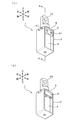
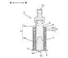
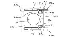
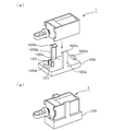
- FIG. 1 It is a perspective view which shows an example of the solenoid which concerns on this invention, (a) shows the front side perspective view, (b) shows the back side perspective view. It is sectional drawing of AA'of the solenoid shown in FIG. It is a front side exploded perspective view of the solenoid shown in FIG. It is a rear side perspective view of the bobbin which constitutes the solenoid shown in FIG. It is a schematic explanatory drawing which shows the connector part which comprises the solenoid shown in FIG. It is a schematic explanatory drawing which shows an example of the terminal metal fitting which constitutes the connector part shown in FIG. FIG.
- FIG. 5 is a cross-sectional view showing a state in which a male terminal is inserted into a connector portion constituting the solenoid shown in FIG. 1.
- It is a front side perspective view which shows the other example of the solenoid which concerns on this invention.
- It is a front side perspective view which shows the other example of the solenoid which concerns on this invention.
- It is a front side exploded perspective view of the solenoid shown in FIG.
- the solenoid 1 includes a yoke 2, a bobbin 3 built in the center of the yoke 2, an electromagnetic coil 4 wound around the bobbin 3, and the bobbin. It is composed of an iron core 5 arranged in the bobbin 3 and a connector portion 6 arranged at one end of the bobbin 3.
- the yoke 2 is composed of a base portion 2a constituting the bottom surface thereof and a pair of standing portions 2b and 2b provided parallel to both ends thereof, and has a U-shaped cross section thereof. 2c is closed by the yoke lid 8.
- the yoke 2 is formed in a U-shaped cross section, but the shape of the yoke may be appropriately selected according to the form of the solenoid to be applied and the like, and has a U-shaped cross section. You can select a shape other than.
- engaging portions 8b and 8b formed at both ends in the longitudinal direction thereof are formed so as to project upward at opposite portions above the standing portions 2b and 2b of the yoke 2, respectively. It is configured to engage with the locking pieces 2e and 2e, and through holes 8a are formed in the central portion thereof in the vertical direction in correspondence with the through holes 6d and 6e in the central portion of the connector portion 6.
- the bobbin 3 is for winding a winding (lead wire) constituting the electromagnetic coil 4, and mainly has a tubular body portion 3a around which the winding is wound, and the body portion 3a.
- a connector portion 6 containing a predetermined number of terminal fittings is arranged at one end portion in the axial direction of the above.
- the bobbin 3 is made of a synthetic resin having an insulating property.
- the bobbin 3 includes a tubular body portion 3a around which a winding is wound and a flat plate-shaped flange portion 3b formed so as to project radially outward at one end of the body portion 3a in the axial direction.
- the case body 6a forming the connector portion 6 is formed at the other end.
- the case body 6a constituting the connector portion 6 is integrally formed with the flange portion on the other end side of the bobbin 3, but the case body 6a and the flange portion are integrally formed. It is also possible to form them as separate bodies without forming them.
- the body portion 3a of the bobbin 3 has a cylindrical shape, but there is no particular limitation on the shape of the bobbin 3, and it is possible to wind a winding (lead wire) such as a square cylinder. It suffices if it is configured to be.
- a through hole 3c is formed through the central portion of the body portion 3a along the axial direction so that the iron core 5 can be arranged inside the central portion.
- a pipe 9 having an inner diameter substantially equal to the outer diameter of the iron core 5 is arranged between the bobbin 3 and the iron core 5, and the inside of the pipe 9 is filled with the iron core 5.
- the plunger (movable iron core) 5a constituting the 5 is configured to slide. Therefore, the through hole 3c is configured to have an inner diameter substantially equal to the outer diameter of the pipe 9.
- the bobbin is composed of one bobbin body, but the bobbin may be configured as a bobbin connector formed by connecting two or more bobbin bodies.
- the number of bobbin bodies can be changed as appropriate according to the application and structure of the solenoid.
- the greatest feature of the present invention is that a terminal fitting that is electrically connected to an external terminal provided by various devices, preferably a connector portion that incorporates a predetermined number of female connection terminals, is built in the center of the yoke. It is provided at one end of the bobbin.
- the connector portion is not particularly limited as long as the terminal fitting is configured to be electrically connected to an external terminal provided in various devices. With such a configuration, the solenoid does not require a relatively large space for providing the lead wire as in the past, so that the solenoid is small and, as a result, can be manufactured at low cost.
- the connector portion 6 incorporates a predetermined number of terminal fittings, and can be provided at one end of the bobbin 3.
- the connector portion 6 is arranged at one end portion (upper end or lower end) in the axial direction of the bobbin 3. With such a configuration, the solenoid can be further miniaturized.
- the connector portion 6 is provided at the upper end of the bobbin 3 and is divided into two in the vertical direction in order to store each member and the like.
- the back side end portions of both side surfaces are formed.
- the opening of the case body 6a while pressing and fixing the case body 6a having an opening on the back surface and the upper part, a predetermined number of terminal metal fittings 7 provided on the case body 6a, and the terminal metal fittings 7 from above. It is composed of a case cover 6b that closes the case.
- the case body 6a constituting the connector portion 6 is integrally formed with the flange portion on the other end side (upper end side in FIGS. 4 and 5) of the bobbin 3, but the case body is formed. It is also possible to form the 6a and the flange portion as separate bodies without forming them integrally.
- the case body 6a has a bottom surface 61a, a front wall 62a formed upright from the front end edge of the bottom surface 61a, and the front wall 62a from the central portion of the bottom surface 61a. It is composed of a pair of side walls 64a and 64a erected on both end edges of a step portion 63a having a required height formed over the above.
- accommodating groove portions 65a and 65a formed by notching a required depth according to each shape of the terminal fittings 71 and 72 are provided at the left and right ends of the step portion 63a.
- the engaging protrusion 66a for engaging with the engaging portions 71b, 72b formed on the front edge side of the terminal fittings 71, 72. , 66a are integrally attached.
- rectangular terminal insertion openings 6f and 6f in a plan view that open laterally are formed through the left and right ends of the front wall 62a of the case body 6a.
- the side openings 6f and 6f are male type provided by various devices as external terminals 101 and 101 with respect to the terminal metal fittings 71 and 72 when the terminal metal fittings 71 and 72 are composed of female terminals. This is for inserting the male terminal when the terminals are electrically contacted.
- the back side of the case body 6a is cut out to a predetermined depth from the outer peripheral side thereof, and the winding guide portion 67a for guiding the winding to the terminal fittings 71 and 72, 67b is formed.
- the terminal fittings 71 and 72 are both made of a conductive material, one end of which is electrically connected to the winding, and the other end of which is an external terminal (various devices) provided with an external connector on the other side (various devices). It is configured to be electrically connected by contacting the contact portion (not shown).
- the terminal fittings 71 and 72 are made of a material having springiness in addition to conductivity, but at least conductive so that they can be electrically connected to the external terminals of the external connector as terminals. It suffices to be composed of a material having the above, and the composition is not particularly limited.
- the form of the terminal fitting can be selected according to the form of the external terminal provided in the device to be mounted, but a female terminal is preferably selected.
- the solenoid does not require a relatively large space for providing a male terminal, and when the solenoid is attached to the device, the female terminal is provided with an external connector provided with the device.
- a male terminal provided as a terminal into (external power supply)
- it can be easily incorporated into the device, so that it is not necessary to connect the solenoid and the device via a connector or a lead wire.
- Assembly efficiency can be greatly improved.
- the terminal fittings 71 and 72 form female terminals having symmetrical shapes, and each of them is formed by punching one plate-shaped body into a predetermined shape. It is formed by bending a punched member in the plate thickness direction.
- the terminal fittings 71, 72 are the terminal bodies 71a, 72a held in the accommodating grooves 65a, 65a of the case body 6a, and the engaging portions 71b formed at the longitudinal front ends of the terminal bodies 71a, 72a. , 72b, elastic contact portions 71c, 72c formed at the tip portions of the engaging portions 71b, 72b, and winding connection portions 71d, 72d formed on the longitudinal trailing edge side of the terminal bodies 71a, 72a. It is composed of ,.
- the engaging portions 71b and 72b are formed by bending the front end portions of the terminal bodies 71a and 72a in the longitudinal direction, and are formed in a U shape that opens outward.
- the engaging portions 71b and 72b engage with the engaging protrusions 66a and 66a of the case body 6a.
- the elastic contact portions 71c and 72c are formed by vertically bending the tips of the engaging portions 71b and 72b so as to be parallel to the terminal bodies 71a and 72a, and are in contact with the external terminals of the external connector. It is something to do. Therefore, the elastic contact portions 71c and 72c can be elastically displaced in the plate thickness direction, and can be elastically contacted with the external terminals (male type terminals) inserted from the terminal insertion ports 6f and 6f. It is configured.
- the winding connection portions 71d and 72d are formed so as to project upward toward the trailing edge side in the longitudinal direction of the terminal bodies 71a and 72a, and are for electrically connecting to the winding.
- terminal bodies 71a and 72a are formed with winding guide portions 71e and 72e for guiding the winding by folding back the extension piece protruding from the rear edge.
- the accommodation is formed by being cut into a predetermined depth according to the shape.
- Grooves 65a and 65a are provided, and engaging protrusions 66a and 66a that engage with the engaging portions 71b and 72b are formed so as to project upward in the accommodating groove portions 65a and 65a. Therefore, by press-fitting the terminal bodies 71a, 72a into the accommodating groove portions 65a, 65a in a state where the engaging portions 71b, 72b and the engaging protrusions 66a, 66a are engaged, the terminal fittings 71, 72 is held by the case body 6a.
- the terminal fittings 71 and 72 are attached to the case body 6a by press fitting into the accommodating groove portions 65a and 65a formed in the step portions 63a, but the terminal fittings are attached to the case.
- the terminal fittings 71 and 72 can be provided on the case body 6a by using a known method such as an integral molding method for embedding in the main body.
- the number of the terminal fittings is two, but the number of terminal fittings can be appropriately changed according to the number of windings forming the electromagnetic coil and the like.
- a through hole 6d is formed in the vertical direction in the central portion of the case body 6a. Further, a through hole 6e is formed in the central portion of the case cover 6b so as to correspond to the through hole 6d in the central portion of the case body 6a, and as shown in FIG. 3, the case body 6a and the case body 6a are described.
- through holes communicating with each other are formed in the vertical direction, and the iron core 5 can be arranged inside the through holes.
- one end (winding start end portion) of the winding is electrically connected to one terminal fitting 71 provided in the connector portion 6, and the winding is further formed.
- the winding drawn from the winding start end of the coil is drawn into the winding guide portion 67a, and then wound around the outer peripheral portion of the body portion 3a in a predetermined winding direction to form an electromagnetic coil 4, and then wound.
- the coil device is configured by pulling it into the wire guide portion 67b and electrically connecting the other end (winding end end portion) to the other terminal fitting 72.
- the coil device having such a configuration has the elastic contact portion with respect to the external terminals (male terminals) 101 and 101 of the external connectors included in the various devices inserted from the terminal insertion ports 6f and 6f. By elastically contacting the 71c and 72c, they are electrically connected to each other.
- the iron core 5 is a cylindrical one made of iron or the like, and is arranged in the bobbin 3.
- the specific configuration of the iron core 5 is not particularly limited, and a known configuration can be adopted depending on the specific configuration and form of the solenoid to be applied.
- the iron core 5 for example, one composed of only a fixed iron core, one composed of only a movable iron core, and one composed of a combination of a fixed iron core and a movable iron core are selected. be able to.
- the iron core 5 has a columnar plunger (movable iron core) 5a that is slidably mounted inside the bobbin 3 and the plunger 5a deviates from the inside of the yoke 2. To prevent this, it is composed of a stopper (fixed iron core) 5b arranged in the lower part of the plunger 5a, and the upper end of the plunger 5a is configured to protrude from the upper surface of the yoke lid 8 by a required length.
- the stopper 5b has a fitting protrusion so as to fit at the lower end thereof with the fitting portion 2d formed at the center of the base portion 2a of the yoke 2. Since the portion 5c is formed, the fitting protrusion 5c is fixed to the base portion 2a of the yoke 2 by fitting with the fitting portion 2d.
- the upper end portion of the stopper 5b is formed in a conical shape, while the lower end portion of the plunger 5a arranged above the stopper 5b is inside in the axial direction.
- a recess facing the upper end of the stopper 5b is formed by notching toward the required depth, and is configured to fit each other.
- the plunger 5a swings in the axial direction due to the magnetic field generated by energizing the electromagnetic coil 4.
- the solenoid 1 is configured such that the plunger 5a is connected to a predetermined member of various devices or devices such as a copying machine via a mounting member 10.
- the device or device may be configured to perform a predetermined operation by connecting the jar 5a to a predetermined member of various devices or devices. Therefore, the mounting member 10 does not necessarily have to be provided.
- a columnar pipe 9 having an outer diameter substantially equal to the inner diameter of the body of the bobbin 3 is disposed in the bobbin 3, and the outer diameter is substantially equal to the inner diameter of the pipe 9.
- the iron core 5 having the above is arranged in the pipe 9.
- the inner surface of the pipe 9 guides the sliding of the plunger 5a constituting the iron core 5 in the pipe 9, and in addition to the effect of smoothing the swing of the plunger 5a, the high temperature environment. It exerts the effect of solving the problem that the plunger 5a is difficult to swing due to the contraction of the bobbin 3 in the lower use.
- the pipe 9 is configured so that its axial length is substantially equal to the length from the upper surface of the yoke lid 8 to the bottom surface of the yoke 2 (upper surface of the base portion 2a), and the pipe 9 is radially outer at one end in the axial direction.
- the flat plate-shaped flange portion that is formed so as to project toward the surface is configured to be locked with the upper surface of the yoke lid 8.
- the plunger 5a swings in the bobbin 3 in the axial direction due to the magnetic field generated from the electromagnetic coil 4 by energizing the external connector (external power supply) provided in various devices.
- various devices connected via the plunger 5a and the mounting member 10 mounted on the upper end thereof also perform a predetermined operation.
- the solenoid configuration is not limited to the above. Therefore, a solenoid composed of a plurality of solenoids such as a U-shaped solenoid, more specifically, a yoke, a bobbin having an electromagnetic coil arranged in the yoke, and an iron core arranged in the bobbin.
- the solenoid according to the present invention also includes a solenoid configured by connecting a plurality of the configured solenoids as one unit.
- the solenoid 11 shown in FIG. 8 shows a modified mode of the solenoid 1 shown in FIG.
- the solenoid 11 has substantially the same configuration as the solenoid 1, but constitutes a so-called flapper type solenoid, and the iron core 15 is composed of only a cylindrical fixed iron core having a predetermined length.
- a connector portion 16 containing a predetermined number of terminal fittings (not shown) is arranged at the lower end of the bobbin 13, and a flapper (movable plate) 18 is swingably placed on the upper portion of the yoke 12 instead of the yoke lid. It differs from the solenoid 1 in that it is mounted.
- the yoke 12 is composed of a base portion 12a constituting the bottom surface thereof and a pair of standing portions 12b, 12b provided parallel to both ends thereof, and is opposed to each other.
- the flapper 18 is swingably mounted on the upper surface of one of the standing portions 12b.
- reference numeral 18a is a locking piece formed by folding the tip of the flapper 18 upward in order to engage the yoke 2 with a cam (not shown) of another device or device, and reference numeral 20a. Is a mounting member for mounting the yoke 12 on a predetermined device or device such as a copying machine.
- an L-shaped protrusion 18b in a side view for engaging the other end of the spring member S is integrally attached to the base end portion of the flapper 18.
- the connector portion 16 is integrally provided at the lower end of the bobbin 13, but has the same configuration as the connector portion 6, and the built-in terminal fitting is in front of the connector portion 16. It is configured to come into contact with external terminals (male terminals) inserted from the terminal insertion ports 16f and 16f of the side openings formed through the wall.
- the iron core 15 is composed of a columnar fixed iron core, but when attached to the yoke 12, the upper surface thereof is flush with the end faces of the upright portions 12b, 12b. It is configured to be. Further, the iron core 15 is arranged in the bobbin 13 with its lower end fixed to the base portion 12a of the yoke 12.
- the flapper 18 When the solenoid 11 having such a configuration is not energized, the flapper 18 is separated from the yoke 12 by the urging force of the spring member S, but when the electromagnetic coil 14 is energized, a magnetic field is generated and the iron core is generated.
- the flapper 18 swingably arranged above the iron core 15 is attracted to the iron core 15.
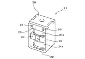
- the solenoid 21 shown in FIG. 9 shows a modified mode of the solenoid 1 shown in FIG.
- the solenoid 21 has substantially the same configuration as the solenoid 1, but as shown in FIG. 10, two bobbins having the same configuration as the bobbin 3 (first bobbin 231 and a first bobbin 231) are used as bobbins.
- the iron core is formed between the pair of stoppers 25b and 25c and the stoppers 25b and 25c. It differs in that it is composed of a plunger 25a that is swingably arranged on the bobbin.
- the bobbin 23 includes a first bobbin 231 as a bobbin, a second bobbin 232 arranged in series (arranged in the axial direction) with respect to the first bobbin 231, and the first bobbin 231 and the first bobbin 23. It is composed of a connecting portion 233 that connects the bobbins 232 of 2 in the axial direction (in series), and as shown in FIG. 11, windings are wound around the bobbins 231 and 232, respectively, to provide electromagnetic coils 24a and 24b.
- the coil device is formed by forming the coil device.
- the connecting portion 233 is formed of a plate-like body having a required size, but one end of the first bobbin 231 and one end of the second bobbin 232 are connected in series. It suffices if it is configured so that it can be connected, and there are no particular restrictions on the configuration.
- Guide grooves 233d and 233e having a required depth are formed at the center and both ends of the radial outer surface of the connecting portion 233 so as to project radially outward and axially. Extending ribs 233a, 233b, 233c are formed.
- the guide grooves 233d and 233e are provided with one end (winding start side) of the winding wound around the outer peripheral portion of the body of the bobbin (first bobbin 231 in FIG. 11) located at a position away from the connector portion 26. It constitutes a winding guide portion for guiding each of the other ends (winding end side) to a predetermined terminal fitting.
- the connector portion 26 has substantially the same configuration as the solenoid 1, and is integrally formed at the upper end of the connecting body 23 as shown in FIG. 11, and is formed in the vertical direction in order to store each member or the like.
- the case body 26a which is divided into two parts and opens the back side end, the back side, and the upper part on both sides, a predetermined number of terminal fittings 27 provided on the case body 26a, and the terminal fittings 27 from above. It is composed of a case cover (not shown) that closes the opening of the case body 26a while pressing and fixing the case body 26a.
- the terminal fitting 27 is composed of three terminal fittings arranged at predetermined intervals, and is provided at both ends of the case body 26a, and is a pair of connection terminals composed of female terminals. It is composed of 71 and 72 and a relay terminal 73 provided in the center of the case body 26a, both of which are made of a conductive metal.
- the first connection terminal 71 has one end of the winding forming the first electromagnetic coil 24a
- the second connection terminal 72 has the winding forming the second electromagnetic coil 24b.
- the other end of the winding that constitutes the first electromagnetic coil 24a and one end of the winding that constitutes the second electromagnetic coil 24b are electrically connected to the relay terminal 73 at the center.
- the iron core 25 is provided at both ends of a plunger 25a that is oscillatedly mounted in the bobbin connecting body 23 in order to prevent the plunger 25a from deviating from the inside of the yoke body 22. It is composed of a pair of stoppers 25b and 25c.
- the stopper 25b is formed by fitting a fitting protrusion 25d formed at the upper end thereof and a fitting portion 28d formed at the center of the yoke lid 28 to fit the yoke lid 28.
- the stopper 25c is fixed to the lower surface, and the stopper 25c is fitted to the fitting protrusion 25d formed at the lower end thereof and the fitting portion 22d formed at the center of the base portion 22a of the yoke 22, thereby fitting the yoke 22. It is fixed to the base 22a of the.
- the upper end of the stopper 25c and the lower end of the stopper 25b are both formed in a conical shape, while both ends of the plunger 25a arranged between the stoppers 25b and 25c face inward in the axial direction.
- the required depth is cut out to form recesses facing each of the lower end portion of the stopper 25b and the upper end portion of the stopper 25c, and are configured to fit each other.
- the stopper 25b is configured to be longer than the stopper 25c by the axial length of the connector portion 26.
- a columnar pipe 29 having an outer diameter substantially equal to the inner diameter of the body portion thereof is disposed in the bobbin connecting body 23, and the inner diameter of the pipe 29 is substantially equal to the inner diameter of the pipe 29.
- the plunger 25a having an outer diameter is configured to be arranged.
- the pipe 29 is configured so that its axial length is substantially equal to the length from the upper surface of the yoke lid 28 to the bottom surface of the yoke 22 (upper surface of the base portion 22a), and the pipe 29 is radially outward at one end in the axial direction.
- the flat plate-shaped flange portion formed so as to protrude is configured to be locked with the lower surface of the bobbin connecting body 23.
- a pair of magnets 30 and 30 are provided between the bobbins 231 and 232 in order to keep the plunger 25a stationary at the central portion of the bobbin connector 233 in a non-energized state. They are placed facing each other.
- the plunger 25a When the solenoid 21 having such a configuration is not energized, the plunger 25a is stationary in the vicinity of the central portion by a pair of magnets 30 and 30 arranged at the central portion in the axial direction of the bobbin connecting body 23. However, when any of the electromagnetic coils 24a and 24b wound around the bobbin coupling 23 is energized, the plunger 25a oscillates in the direction of the energized electromagnetic coil.
- the guide bar G Since the plunger 25a is connected to a predetermined member of various devices or devices via a guide bar G as a mounting member, the guide bar G also swings in the axial direction as the plunger 5a swings. It moves, and as a result, a predetermined operation is performed in this device or device.
- the terminal fittings in which the connector portion of the solenoid 1 incorporates the external terminals (male type terminals) 100b and 100b provided in the external connector Locking of a pair of snap-fit structures erected facing each other at predetermined intervals so as to support the left-right direction of the solenoid 1 from above while inserting from an insertion port formed in the vicinity of (female terminal).
- the left and right side edges of the solenoid 1 are elastically deformed outward to the locking claws 100c and 100c.
- the solenoid 1 is elastically restored to its original position and locked to each other, and the fixed pieces 100d and 100d support the upper and lower side edges of the solenoid 1, so that the solenoid 1 can be moved to a predetermined position of the device 100. It can be performed with one touch on the mounting portion 100a provided at the position. Therefore, the solenoid of the present invention can be easily attached to various devices simply by fitting it into a predetermined position of the device.
- the solenoid according to the present invention is inexpensive and compact because a predetermined number of terminal fittings, particularly a connector portion containing a female terminal, is provided at one end of a bobbin having an electromagnetic coil arranged in a yoke. Since it can be easily attached to various devices, the solenoid can be used in a wide range of fields.
Abstract
【課題】 安価かつ小型で、リード線を設けることなく、各種機器に簡単に取付けることができるソレノイドの提供を目的とする。 【解決手段】 この発明のソレノイド1は、ヨーク2と、前記ヨーク2内に配置される電磁コイル4を有するボビン3と、前記ボビン3内に配置される鉄芯5で構成されるもので、前記ボビン3の一端部には、所定の数の端子金具7を内蔵するコネクタ部6が設けられている。 したがって、従前のようにリード線を設けるための比較的大きなスペースを必要としないので、小型であり、その結果、安価に製造することができる
Description
この発明は、レジスターの金銭ボックスのカギや、自動車のシフトレバーのロック解除機構など各種機器に使用されるソレノイドに関するものである。
より詳しくは、安価かつ小型で、簡単に取り付けることができるソレノイドに関するものである。
より詳しくは、安価かつ小型で、簡単に取り付けることができるソレノイドに関するものである。
既存のソレノイドは、一般的には、底面の相対する側縁に、上方に起立する側壁を有する、断面チャンネル状のヨーク本体と、前記底面上に固定されるストッパ受けと、前記プランジャーに装着されるプランジャー(鉄芯)、および前記ヨークの開口部を閉止するヨークフタとから構成されている。
従来、ソレノイドは、そのコネクタ部(オス型端子)に差し込まれる、相手側のコネクタ(メス型端子)を介して、コイルが通電されると、コイルのまわりに磁界が発生するよう構成されている。
かかるソレノイドの一例が、特許文献1に開示されている。
かかるソレノイドの一例が、特許文献1に開示されている。
特開2013-222806号公報(特許文献1)には、ヨーク内に配置される電磁コイルを有するボビンと、前記ボビン内に配置される磁性芯と、基端部に係着されるスプリング部材によって前記ヨーク上に揺動自在に配置されるフラッパを主構成要素とするソレノイドであって、
少なくとも、前記ボビンと前記ボビン上に揺動自在に設けられるフラッパとが、プラスチック材料で形成され、前記ボビンとフラッパが、断面円弧状のスプリング部材で一体的に連結されていることを特徴とするフラッパ型ソレノイドが提案されている。
少なくとも、前記ボビンと前記ボビン上に揺動自在に設けられるフラッパとが、プラスチック材料で形成され、前記ボビンとフラッパが、断面円弧状のスプリング部材で一体的に連結されていることを特徴とするフラッパ型ソレノイドが提案されている。
このフラッパ型ソレノイドは、リード線を介してコイルが通電されると、コイルのまわりに磁界が発生するよう構成されたものである。
前記特許文献1に開示されているフラッパ型ソレノイドなど、従来のソレノイドでは、一般的に、コイルへの通電によって、このコイルのまわりに磁界が発生するよう、ソレノイドと相手(各種機器)側とを、前記ソレノイドに設けられたコネクタ部に突設されたオス型端子を相手側のコネクタ部に設けられたメス型端子へ挿入することにより、或いはリード線を介して、互いに接続するように構成される。
したがって、従来のソレノイドでは、コネクタ部やリード線を設けるためのスペースを必要とする、という問題があった。
したがって、従来のソレノイドでは、コネクタ部やリード線を設けるためのスペースを必要とする、という問題があった。
さらに、従来、ソレノイドの各種の機器への取付けに際しては、ソレノイド本体を前記機器に取付けた後に、前記ソレノイドと前記機器とを、コネクタ部又はリード線を介して接続する、という二つの工程が必要とされるため取付けが煩雑である、という問題もあった。
この発明はかかる現状に鑑み、安価かつ小型で、リード線を設けることなく、各種機器に簡単に取付けることができるソレノイドを提供せんとするものである。
前記目的を達成するため、この発明にかかる請求項1に記載の発明は、
この発明の請求項1に記載の発明は、
ヨークと、前記ヨーク内に配置される電磁コイルを有するボビンと、前記ボビン内に配置される鉄芯で構成されるソレノイドであって、
前記ボビンの一端部に、所定の数の端子金具を内蔵するコネクタ部が設けられていること
を特徴とするソレノイドである。
この発明の請求項1に記載の発明は、
ヨークと、前記ヨーク内に配置される電磁コイルを有するボビンと、前記ボビン内に配置される鉄芯で構成されるソレノイドであって、
前記ボビンの一端部に、所定の数の端子金具を内蔵するコネクタ部が設けられていること
を特徴とするソレノイドである。
この発明の請求項2に記載の発明は、
請求項1に記載のソレノイドにおいて、
前記端子金具のうち、前記ソレノイドが装着される機器に備えられている外部端子と電気的に接続される端子は、
メス型端子で構成されていること
を特徴とするものである。
請求項1に記載のソレノイドにおいて、
前記端子金具のうち、前記ソレノイドが装着される機器に備えられている外部端子と電気的に接続される端子は、
メス型端子で構成されていること
を特徴とするものである。
この発明の請求項3に記載の発明は、
請求項1又は2に記載のソレノイドにおいて、
前記コネクタ部は、
前記ボビンの軸方向一端部に設けられていること
を特徴とするものである。
請求項1又は2に記載のソレノイドにおいて、
前記コネクタ部は、
前記ボビンの軸方向一端部に設けられていること
を特徴とするものである。
この発明の請求項4に記載の発明は、
請求項1~3のいずれかに記載のソレノイドにおいて、
前記ヨークは、
断面コ字状体からなるもので、その上部開口部を閉止するヨークフタを備え、
前記コネクタ部は、
前記ボビンの上方に設けられ、
前記鉄芯は、
下端が前記ヨークの底面に固定される固定鉄芯と、前記固定鉄芯の上部に揺動自在に配置される可動鉄芯で構成されていること
を特徴とするものである。
請求項1~3のいずれかに記載のソレノイドにおいて、
前記ヨークは、
断面コ字状体からなるもので、その上部開口部を閉止するヨークフタを備え、
前記コネクタ部は、
前記ボビンの上方に設けられ、
前記鉄芯は、
下端が前記ヨークの底面に固定される固定鉄芯と、前記固定鉄芯の上部に揺動自在に配置される可動鉄芯で構成されていること
を特徴とするものである。
この発明の請求項5に記載の発明は、
請求項1に記載のソレノイドにおいて、
前記ヨークは、
断面コ字状体からなるもので、その上部開口部を閉止するヨークフタを備え、
前記ボビンは、
2つのボビンが軸方向に連結した連結体として構成され、
前記鉄芯は、
上端が前記ヨークフタの下面に固定される第1の固定鉄芯と、下端が前記ヨークの底面に固定される第2の固定鉄芯と、前記第1の固定鉄芯と前記第2の固定鉄芯との間に搖動自在に配置される可動鉄芯で構成され、
前記コネクタ部は、
所定の間隔を存して配置される3つの端子金具を内蔵し、
前記電磁コイルのうち、第1の電磁コイルを構成する巻線の一端が第1の端子金具に、第1の電磁コイルを構成する巻線の他端と第2の電磁コイルを構成する巻線の一端が第2の端子金具に、第2の電磁コイルを構成する巻線の他端が第3の端子金具に、それぞれ電気的に接続されていること
を特徴とするものである。
この発明の請求項6に記載の発明は、
請求項5に記載のソレノイドにおいて、
前記第1及び第3の端子金具は、
いずれもメス型端子で構成され、
前記連結体は、
そのボビン間に対向して配置される一対のマグネットを備えること
を特徴とするものである。
請求項5に記載のソレノイドにおいて、
前記第1及び第3の端子金具は、
いずれもメス型端子で構成され、
前記連結体は、
そのボビン間に対向して配置される一対のマグネットを備えること
を特徴とするものである。
この発明の請求項7に記載の発明は、
請求項1に記載のソレノイドにおいて、
前記ヨークは、
その上部に揺動自在に装着されるフラッパを備え、
前記鉄芯は、
下端が前記ヨークの底面に固定される固定鉄芯で構成され、
前記ヨークの起立部の端面は、いずれも、前記鉄芯を取り付けた状態において、前記鉄芯の上面と面一になるように構成されていること
を特徴とするものである。
請求項1に記載のソレノイドにおいて、
前記ヨークは、
その上部に揺動自在に装着されるフラッパを備え、
前記鉄芯は、
下端が前記ヨークの底面に固定される固定鉄芯で構成され、
前記ヨークの起立部の端面は、いずれも、前記鉄芯を取り付けた状態において、前記鉄芯の上面と面一になるように構成されていること
を特徴とするものである。
この発明の請求項8に記載の発明は、
請求項7に記載のソレノイドにおいて、
前記コネクタ部は、
前記ボビンの下方に設けられ、
前記フラッパは、
前記ヨークの一方の起立部上に形成された軸杆に支承され、かつ前記ヨークと前記フラッパとの間にスプリング部材を装着することによって搖動自在に構成されていること
を特徴とするものである。
請求項7に記載のソレノイドにおいて、
前記コネクタ部は、
前記ボビンの下方に設けられ、
前記フラッパは、
前記ヨークの一方の起立部上に形成された軸杆に支承され、かつ前記ヨークと前記フラッパとの間にスプリング部材を装着することによって搖動自在に構成されていること
を特徴とするものである。
この発明の請求項9に記載の発明は、
請求項8に記載のソレノイドにおいて、
前記コネクタ部は、
前記ボビンの下端に一体的に設けられていること
を特徴とするものである。
請求項8に記載のソレノイドにおいて、
前記コネクタ部は、
前記ボビンの下端に一体的に設けられていること
を特徴とするものである。
この発明のソレノイドは、ヨークと、前記ヨーク内に配置される電磁コイルを有するボビンと、前記ボビン内に配置される鉄芯で構成されるもので、前記ボビンの一端部に、所定の数の端子金具を内蔵するコネクタ部を設けたものである。
したがって、このソレノイドは、従前のようにリード線を設けるための比較的大きなスペースを必要としないので、小型であり、その結果、安価に製造することができるものである。
したがって、このソレノイドは、従前のようにリード線を設けるための比較的大きなスペースを必要としないので、小型であり、その結果、安価に製造することができるものである。
前記ソレノイドにおいては、前記端子金具のうち、このソレノイドが装着される各種機器に備えられている外部端子と電気的に接続される端子を、メス型端子で構成することができる。
このような構成によって、前記ソレノイドは、オス型端子を設けるための比較的大きなスペースを必要としないことに加え、その前記機器への装着に際しては、前記メス型端子に、前記機器が備える外部コネクタ(外部電源)に端子として備えられたオス型端子を挿入することによって、簡単に前記機器に組み込むことができるので、ソレノイドと前記機器とを、コネクタ部又はリード線を介して接続する必要がなくなり、組立て効率を大幅に改善することができる。
このような構成によって、前記ソレノイドは、オス型端子を設けるための比較的大きなスペースを必要としないことに加え、その前記機器への装着に際しては、前記メス型端子に、前記機器が備える外部コネクタ(外部電源)に端子として備えられたオス型端子を挿入することによって、簡単に前記機器に組み込むことができるので、ソレノイドと前記機器とを、コネクタ部又はリード線を介して接続する必要がなくなり、組立て効率を大幅に改善することができる。
さらに、前記ソレノイドおいては、前記コネクタ部を、前記ボビンの軸方向一端部に配設することができる。
このような構成によって、ソレノイドの更なる小型化が可能となる。
このような構成によって、ソレノイドの更なる小型化が可能となる。
前記ソレノイドおいては、前記ボビンを、2つのボビンが軸方向に連結した連結体として構成し、前記鉄芯を、上端が前記ヨークフタの下面に固定される第1の固定鉄芯と、下端が前記ヨークの底面に固定される第2の固定鉄芯と、前記第1の固定鉄芯と前記第2の固定鉄芯との間に搖動自在に配置される可動鉄芯で構成し、前記コネクタ部を、内部に所定の間隔を存して3個のメス型端子を具備し、前記電磁コイルのうち、第1の電磁コイルを構成する巻線の一端が第1のメス型端子に、第1の電磁コイルを構成する巻線の他端と第2の電磁コイルを構成する巻線の一端が第2のメス型端子に、第2の電磁コイルを構成する巻線の他端が第3のメス型端子に、それぞれ電気的に接続されたもので構成することができる。
このような構成によって、前記連結体に巻回されている上下2つの電磁コイルのうち、いずれかの電磁コイルに通電した場合に、可動鉄芯が、通電した電磁コイルの方向に搖動する。
このような構成によって、前記連結体に巻回されている上下2つの電磁コイルのうち、いずれかの電磁コイルに通電した場合に、可動鉄芯が、通電した電磁コイルの方向に搖動する。
以下、この発明にかかるソレノイドについて、添付の図面に基づいて具体的に説明する。
なお、この発明は開示された実施例にのみ限定されるものではなく、その要旨を変更しない範囲内において種々改良することができるものである。
なお、この発明は開示された実施例にのみ限定されるものではなく、その要旨を変更しない範囲内において種々改良することができるものである。
この発明にかかるソレノイド1は、図1~3に示すように、ヨーク2と、前記ヨーク2の中心部に内装されるボビン3と、前記ボビン3に巻回された電磁コイル4と、前記ボビン3内に配置される鉄芯5と、前記ボビン3の一端部に配設されるコネクタ部6と、から構成されるものである。
図1~3において、前記ヨーク2は、その底面を構成する基部2aと、その両端に平行に設けられた一対の起立部2b,2bからなる断面コ字状体で構成され、その上部開口部2cは、ヨークフタ8によって閉止されている。
なお、図1~3において、前記ヨーク2は、断面コ字状に形成されているが、ヨークの形状については、適用されるソレノイドの形態などに応じて適宜選択すればよく、断面コ字状以外の形状を選択することができる。
なお、図1~3において、前記ヨーク2は、断面コ字状に形成されているが、ヨークの形状については、適用されるソレノイドの形態などに応じて適宜選択すればよく、断面コ字状以外の形状を選択することができる。
図3において、前記ヨークフタ8は、その長手方向両端部に形成される係合部8b,8bが、それぞれ前記ヨーク2の起立部2b,2bの上部の相対する部位に上方に向かって突出形成された係止片2e,2eと係合するよう構成され、その中央部には、前記コネクタ部6の中央部の貫通孔6d,6eと対応させて透孔8aが上下方向に形成されている。
前記ボビン3は、電磁コイル4を構成する巻線(導線)を巻回するためのもので、巻線が巻回される筒状の胴部3aを主体とするものであり、前記胴部3aの軸方向一端部には、所定の数の端子金具を内蔵するコネクタ部6が配設される。
る。
なお、この実施例において、前記ボビン3は、絶縁性を有する合成樹脂で構成されている。
る。
なお、この実施例において、前記ボビン3は、絶縁性を有する合成樹脂で構成されている。
図4において、ボビン3は、巻線が巻回される筒状の胴部3aと、前記胴部3aの軸方向の一端に径方向外側に向かって突出形成された平板状のフランジ部3bと、他端に形成された、前記コネクタ部6を構成するケース本体6aで構成されている。
このような構成によって、ソレノイドの更なる小型化が可能となる。
このような構成によって、ソレノイドの更なる小型化が可能となる。
なお、この実施例においては、前記コネクタ部6を構成するケース本体6aを、前記ボビン3の他端側のフランジ部と一体に形成する構成としているが、ケース本体6aとフランジ部とを一体に形成せず、それぞれ別体として形成することも可能である。
また、図4において、前記ボビン3の胴部3aは円筒状であるが、前記ボビン3の形状については、特段の制限はなく、角筒状など、巻線(導線)の巻回が可能となるよう構成されていればよい。
図1~3において、前記胴部3aの中央部には、その内部に前記鉄芯5が配置可能となるよう、軸方向に沿って貫通孔3cが貫通形成されている。
なお、図1~3において、前記ボビン3と前記鉄芯5との間には、前記鉄芯5の外径とほぼ等しい内径を有するパイプ9を配置し、このパイプ9内を、前記鉄芯5を構成するプランジャー(可動鉄芯)5aが摺動するよう構成されている。
したがって、前記貫通孔3cは、前記パイプ9の外径とほぼ等しい内径を有するよう構成されている。
したがって、前記貫通孔3cは、前記パイプ9の外径とほぼ等しい内径を有するよう構成されている。
この実施例において、前記ボビンは1つのボビン本体で構成されたものであるが、前記ボビンを、2以上のボビン本体を連結してなるボビン連結体として構成してもよい。
なお、ボビン本体の個数については、ソレノイドの用途や構造などに応じて、適宜変更することが可能である。
なお、ボビン本体の個数については、ソレノイドの用途や構造などに応じて、適宜変更することが可能である。
この発明の最大の特徴は、各種機器が具備する外部端子と電気的に接続される端子金具、好ましくはメス型の接続端子を所定の数で内蔵するコネクタ部を、ヨークの中心部に内装されるボビンの一端部に設けるものである。
かかるコネクタ部については、前記端子金具が、各種機器が具備する外部端子と電気的に接続されるように構成されていれば、その構成に特段の制限はないものである。
このような構成によって、ソレノイドは、従前のようにリード線を設けるための比較的大きなスペースを必要としないので、小型であり、その結果、安価に製造することが可能となる。
かかるコネクタ部については、前記端子金具が、各種機器が具備する外部端子と電気的に接続されるように構成されていれば、その構成に特段の制限はないものである。
このような構成によって、ソレノイドは、従前のようにリード線を設けるための比較的大きなスペースを必要としないので、小型であり、その結果、安価に製造することが可能となる。
前記コネクタ部6は、所定の数の端子金具を内蔵するもので、前記ボビン3の一端部に設けることができるものである。
好ましくは、前記コネクタ部6は、前記ボビン3の軸方向一端部(上端又は下端)に配設される。
このような構成によって、ソレノイドの更なる小型化が可能となる。
好ましくは、前記コネクタ部6は、前記ボビン3の軸方向一端部(上端又は下端)に配設される。
このような構成によって、ソレノイドの更なる小型化が可能となる。
図5において、前記コネクタ部6は、前記ボビン3の上端に設けられ、各部材などを収納するために、上下方向に2分割されており、この実施例においては、両側面の背面側端部と背面と上部が開口するケース本体6aと、このケース本体6a上に設けられる所定の数の端子金具7と、前記端子金具7を上から押圧して固定しつつ、前記ケース本体6aの開口部を閉止するケースカバー6bから構成されている。
なお、図4及び5において、前記コネクタ部6を構成するケース本体6aは、前記ボビン3の他端側(図4及び5において上端側)のフランジ部と一体に形成されているが、ケース本体6aとフランジ部とを一体に形成せず、それぞれ別体として形成することも可能である。
この実施例において、前記ケース本体6aは、図5に示すように、底面61aと、この底面61aの前端縁から起立して形成された前壁62aと、底面61aの中央部から前記前壁62aに亘って形成される所要の高さの段部63aの両端縁に立設された一対の側壁64a,64aで構成されている。
図5において、前記段部63aの左右端部には、前記端子金具71,72の各形状に合わせて所要の深さ切り欠いて形成された収容溝部65a,65aが設けられている。
さらに、図5において、前記収容溝部65a,65a内の前端側には、前記端子金具71,72の前縁側に形成されている係合部71b,72bと係合するための係合突部66a,66aが一体的に付設されている。
なお、図1~5において、前記ケース本体6aの前壁62aの左右端部には、側方に開口する平面視長方形の端子挿入口6f,6fが貫通形成されている。
前記側方開口部6f,6fは、前記端子金具71,72がメス型端子で構成されている場合において、前記端子金具71,72に対して、各種機器が外部端子101,101として備えるオス型端子を電気的に接触させる際に、前記オス型端子を挿入するためのものである。
前記側方開口部6f,6fは、前記端子金具71,72がメス型端子で構成されている場合において、前記端子金具71,72に対して、各種機器が外部端子101,101として備えるオス型端子を電気的に接触させる際に、前記オス型端子を挿入するためのものである。
さらに、前記ケース本体6aの背面側には、図5に示すように、その外周側から所定の深さ切り欠いて、巻線を端子金具71,72にガイドするための巻線ガイド部67a,67bが形成されている。
前記端子金具71,72は、いずれも導電性を有する材料で構成され、その一端側が巻線と電気的に接続され、他端側が相手側(各種機器)の外部コネクタに備えられた外部端子(図示せず)の接点部と接触することで電気的に接続されるように構成されたものである。
なお、この実施例において、前記端子金具71,72は、導電性に加えてバネ性を有する材料で構成されているが、端子として、外部コネクタの外部端子と電気的に接続できるよう少なくとも導電性を有する材料で構成されていればよく、その構成に特段の制限はないものである。
なお、この実施例において、前記端子金具71,72は、導電性に加えてバネ性を有する材料で構成されているが、端子として、外部コネクタの外部端子と電気的に接続できるよう少なくとも導電性を有する材料で構成されていればよく、その構成に特段の制限はないものである。
前記端子金具の形態については、装着される機器が備える外部端子の形態に応じて選択することができるが、好ましくはメス型端子が選択される。
このような構成によって、前記ソレノイドは、オス型端子を設けるための比較的大きなスペースを必要としないことに加え、その前記機器への装着に際しては、前記メス型端子に、前記機器が備える外部コネクタ(外部電源)に端子として備えられたオス型端子を挿入することによって、簡単に前記機器に組み込むことができるので、ソレノイドと前記機器とを、コネクタ部又はリード線を介して接続する必要がなくなり、組立て効率を大幅に改善することができる。
このような構成によって、前記ソレノイドは、オス型端子を設けるための比較的大きなスペースを必要としないことに加え、その前記機器への装着に際しては、前記メス型端子に、前記機器が備える外部コネクタ(外部電源)に端子として備えられたオス型端子を挿入することによって、簡単に前記機器に組み込むことができるので、ソレノイドと前記機器とを、コネクタ部又はリード線を介して接続する必要がなくなり、組立て効率を大幅に改善することができる。
この実施例において、前記端子金具71,72は、図6に示すように、互いに対称形状をなすメス型端子を構成するもので、いずれも一枚の板状体を所定の形状に打ち抜いて形成した打ち抜き部材を板厚方向に折り曲げて形成されたものである。前記端子金具71,72は、前記ケース本体6aの収容溝部65a,65a内に保持される端子本体71a,72aと、前記端子本体の71a,72aの長手方向前端部に形成された係合部71b,72bと、前記係合部71b,72bの先端部に形成された弾性接触部71c,72cと、前記端子本体の71a,72aの長手方向後縁側に形成された巻線接続部71d,72dと、で構成されている。
前記係合部71b,72bは、前記端子本体の71a,72aの長手方向前端部を折り曲げて形成されたもので、外側に開口したコ字状に形成されている。この係合部71b,72bは、前記ケース本体6aの係合突部66a,66aと係合する。
前記弾性接触部71c,72cは、係合部71b,72bの先端部を、端子本体の71a,72aと平行になるよう後方に鉛直に折り曲げて形成されたもので、外部コネクタの外部端子と接触するものである。
したがって、前記弾性接触部71c,72cは、板厚方向に弾性変位可能で、前記端子挿入口6f,6fから挿入された外部端子(オス型端子)と弾性的に接触することが可能となるよう構成されている。
したがって、前記弾性接触部71c,72cは、板厚方向に弾性変位可能で、前記端子挿入口6f,6fから挿入された外部端子(オス型端子)と弾性的に接触することが可能となるよう構成されている。
前記巻線接続部71d,72dは、端子本体71a,72aの長手方向後縁側に上方に向かって突出形成されたもので、巻線と電気的に接続するためのものである。
さらに、前記端子本体71a,72aには、その後端縁から突出した延長片を折り返して、巻線をガイドするための巻線ガイド部71e,72eが形成されている。
前記したように、図5において、前記ケース本体6aの段部63aの左右端部には、前記端子金具71,72を圧入するため、その形状に合わせて所定の深さで切り込み形成された収容溝部65a,65aが設けられ、この収容溝部65a,65aには、前記係合部71b,72bと係合する係合突部66a,66aが上方に向かって突出形成されている。
したがって、前記係合部71b,72bと前記係合突部66a,66aを係合させた状態で、前記端子本体71a,72aを前記収容溝部65a,65aに圧入することによって、前記端子金具71,72が前記ケース本体6aに保持される。
したがって、前記係合部71b,72bと前記係合突部66a,66aを係合させた状態で、前記端子本体71a,72aを前記収容溝部65a,65aに圧入することによって、前記端子金具71,72が前記ケース本体6aに保持される。
なお、この実施例において、前記端子金具71,72を、前記ケース本体6aに対して、その段部63aに形成された収容溝部65a,65a内に圧入によって装着しているが、端子金具をケース本体内に一体成形によって埋設する方法など公知の方法を利用して、前記ケース本体6aに前記端子金具71,72を設けることができる。
また、この実施例において、前記端子金具の数は2つとしているが、端子金具の数は、電磁コイルを形成する巻線の数などに応じて適宜変更することができる。
図5において、前記ケース本体6aの中央部には、貫通孔6dが上下方向に形成されている。
さらに、前記ケースカバー6bの中央部には、前記ケース本体6aの中央部の貫通孔6dと対応させて貫通孔6eが形成され、図3に示されているように、前記ケース本体6aと前記ケースカバー6bを結合させると、互いに連通する貫通孔が上下方向に形成され、その内部に鉄芯5を配置することができるように構成されている。
さらに、前記ケースカバー6bの中央部には、前記ケース本体6aの中央部の貫通孔6dと対応させて貫通孔6eが形成され、図3に示されているように、前記ケース本体6aと前記ケースカバー6bを結合させると、互いに連通する貫通孔が上下方向に形成され、その内部に鉄芯5を配置することができるように構成されている。
かかる構成の、コネクタ部が配設されたボビンは、例えば、巻線の一端(巻き始め端部)を、コネクタ部6が具備する一方の端子金具71に電気的に接続し、さらに前記巻線の巻き始め端部から引き出された巻線を、巻線ガイド部67aに引き込み、ついで前記胴部3aの外周部に所定の巻回方向に向かって巻回して電磁コイル4を形成した後、巻線ガイド部67bに引き込み、他端(巻き終わり端部)を、他方の端子金具72に電気的に接続することにより、コイル装置を構成する。
かかる構成のコイル装置は、図7に示すように、前記端子挿入口6f,6fから挿入された、各種機器が備える外部コネクタの外部端子(オス型端子)101,101対して、前記弾性接触部71c,72cが弾性的に接触することによって、互いが電気的に接続されるものである。
前記鉄芯5は、鉄などで構成される円筒状のもので、前記ボビン3内に配置されるものである。
前記鉄芯5の具体的な構成は特に限定されず、適用されるソレノイドの具体的な構成や形態などに応じて公知の構成を採用することができる。
前記鉄芯5としては、例えば、固定鉄芯のみで構成されているもの、可動鉄芯のみで構成されているもの、固定鉄芯と可動鉄芯との組み合わせで構成されているものを選択することができる。
前記鉄芯5としては、例えば、固定鉄芯のみで構成されているもの、可動鉄芯のみで構成されているもの、固定鉄芯と可動鉄芯との組み合わせで構成されているものを選択することができる。
図1~3において、前記鉄芯5は、前記ボビン3の内部に搖動自在に装着される円柱状のプランジャー(可動鉄芯)5aと、前記プランジャー5aがヨーク2内から逸脱するのを防止するため前記プランジャー5aの下部に配されるストッパ(固定鉄芯)5bで構成され、前記プランジャー5aの上端が前記ヨークフタ8の上面から所要長さ突出するよう構成されている。
具体的には、前記ストッパ5bは、図2及び3に示すように、その下端部に、前記ヨーク2の基部2aの中央部に形成された嵌合部2dと嵌合するよう、嵌合突部5cが形成されているので、前記嵌合突部5cが嵌合部2dと嵌合することによってヨーク2の基部2aに固定される。
さらに、図2及び3に示すように、前記ストッパ5bの上端部は、截頭円錐形状に形成される一方、前記ストッパ5bの上部に配置されるプランジャー5aの下端には、軸方向内部に向かって所要深さ切り欠いて、前記ストッパ5bの上端部と対面する窪みが形成され、互いが嵌合するように構成されている。
このような構成によって、前記ボビン3内において、前記プランジャー5aは、前記電磁コイル4への通電により発生する磁界によって軸方向に揺動する。
なお、図1~3において、ソレノイド1は、前記プランジャー5aが、取付部材10を介して、複写機などの各種機器ないし装置の所定の部材と連結されるよう構成されているが、前記プランジャー5aが各種機器ないし装置の所定の部材と連結されることによって、この機器ないし装置が所定の動作を行うよう構成されていればよい。
したがって、前記取付部材10は、必ずしも設けることを要しないものである。
したがって、前記取付部材10は、必ずしも設けることを要しないものである。
さらに、図1~3において、前記ボビン3内には、前記ボビン3の胴部の内径とほぼ等しい外径を有する円柱状のパイプ9が配設され、前記パイプ9の内径とほぼ等しい外径を有する前記鉄芯5が前記パイプ9内に配置されるよう構成されている。
このパイプ9は、その内面によって、前記鉄芯5を構成するプランジャー5aの前記パイプ9内の摺動をガイドし、前記プランジャー5aの揺動を円滑にするという作用効果に加え、高温環境下での使用におけるボビン3の収縮によって前記プランジャー5aが揺動しづらくなるという問題を解消するという作用効果を発揮するものである。
このパイプ9は、その内面によって、前記鉄芯5を構成するプランジャー5aの前記パイプ9内の摺動をガイドし、前記プランジャー5aの揺動を円滑にするという作用効果に加え、高温環境下での使用におけるボビン3の収縮によって前記プランジャー5aが揺動しづらくなるという問題を解消するという作用効果を発揮するものである。
なお、前記パイプ9は、その軸方向の長さが、ヨークフタ8の上面からヨーク2の底面(基部2aの上面)までの長さとほぼ等しくなるよう構成され、その軸方向の一端に径方向外側に向かって突出形成された平板状のフランジ部がヨークフタ8の上面と係止するよう構成されている。
かかる構成のソレノイド1によれば、各種機器が備える外部コネクタ(外部電源)との通電により前記電磁コイル4から発生する磁界によって、前記プランジャー5aが前記ボビン3内を軸方向に揺動するので、前記プランジャー5aの揺動に伴って、前記プランジャー5aと、その上端に装着された取付部材10を介して、連結された各種機器も所定の動作を行うこととなる。
この発明において、ソレノイドの構成は上記に限定されない。したがって、U型ソレノイドなどの複数のソレノイドで構成されたもの、より具体的には、ヨークと、前記ヨーク内に配置される電磁コイルを有するボビンと、前記ボビン内に配置される鉄芯とで構成されたものを1単位としてこれを複数連結して構成されたソレノイドも、本願発明におけるソレノイドに包含される。
図8に示すソレノイド11は、図1に示すソレノイド1の変形態様を示すものである。
前記ソレノイド11は、前記ソレノイド1とほぼ同様の構成を有するものであるが、いわゆるフラッパ型のソレノイドを構成するものであり、鉄芯15を所定の長さの円柱状の固定鉄芯のみで構成し、所定の数の端子金具(図示せず)を内蔵するコネクタ部16をボビン13の下端に配設し、ヨーク12の上部に、ヨークフタに代えてフラッパ(可動板)18を揺動自在に装着させた点で前記ソレノイド1とは異なっている。
図8に示すように、前記ヨーク12は、その底面を構成する基部12aと、その両端に平行に設けられた一対の起立部12b,12bからなる断面コ字状体からなるもので、相対する一方の起立部12bの上面には、前記フラッパ18が揺動自在に装着されている。
なお、図8において、符号18aは、ヨーク2を、他の機器ないし装置のカム(図示せず)と係合するためフラッパ18の先端部を上方に折り返して形成した係止片で、符号20は、ヨーク12を、複写機などの所定の機器ないし装置に装着するための取付部材である。
前記ヨーク12の一方の起立部12bの外面中央部には、前記フラッパ18を常時ヨーク12から離反させる方向に付勢するスプリング部材Sの一端が係合する突起12gがやや下方に向けて突設されている。
一方、前記フラッパ18の基端部には、図8に示すように、スプリング部材Sの他端が係合するための側面視L字状の突出部18bが一体的に付設されている。
前記コネクタ部16は、前記ボビン13の下端に一体的に設けられたものであるが、前記コネクタ部6と同様の構成を有するもので、内蔵されている端子金具が、前記コネクタ部16の前壁に貫通形成された側方開口の端子挿入口16f,16fから挿入された外部端子(オス型端子)と接触するよう構成されている。
図8において、前記鉄芯15は、円柱状の固定鉄芯で構成されたものであるが、前記ヨーク12に取り付けた状態において、その上面が、前記起立部12b,12bの端面と面一になるように構成されている。
さらに、前記鉄芯15は、その下端がヨーク12の基部12aに固定された状態で、前記ボビン13内に配置される。
さらに、前記鉄芯15は、その下端がヨーク12の基部12aに固定された状態で、前記ボビン13内に配置される。
かかる構成のソレノイド11は、通電しない状態においては、前記スプリング部材Sの付勢力によって前記フラッパ18は前記ヨーク12から離反しているが、前記電磁コイル14に通電すると磁界が発生し、前記鉄芯15の上部に揺動自在に配置された前記フラッパ18は、前記鉄芯15に吸着されるものである。
図9に示すソレノイド21は、図1に示すソレノイド1の変形態様を示すものである。
前記ソレノイド21は、前記ソレノイド1とほぼ同様の構成を有するものであるが、図10に示すように、ボビンとして、前記ボビン3と同様の構成を有する2つのボビン(第1のボビン231と第2のボビン232)の各端部を、連結部233を介して軸方向に連結して形成したボビン連結体23を使用し、鉄芯を、一対のストッパ25b,25cと前記ストッパ25b,25c間に揺動自在に配置されるプランジャー25aで構成した点で異なる。
前記ボビン23は、ボビンとして、第1のボビン231と、前記第1のボビン231に対して直列に(軸方向に並べて)配置される第2のボビン232と、前記第1のボビン231及び第2のボビン232を軸方向(直列)に連結する連結部233で構成されたもので、図11に示すように、前記ボビン231,232のそれぞれに巻線を巻回して電磁コイル24a,24bを形成することによってコイル装置を構成するものである。
なお、この実施例において、前記連結部233は、所要の大きさの板状体で構成されているが、前記第1のボビン231の一端部と前記第2のボビン232の一端部を直列に連結できるように構成されていればよく、その構成に特段の制限はないものである。
前記連結部233の径方向外面の中央部及び両端部には、所定の間隔を存して所要の深さのガイド溝233d,233eを形成することによって、径方向外方に突出し且つ軸方向に延びるリブ233a,233b,233cが、形成されている。
前記ガイド溝233d,233eは、前記コネクタ部26から離れた位置にあるボビン(図11において第1のボビン231)の胴部の外周部に巻回される巻線の一端(巻き始め側)と他端(巻き終わり側)のそれぞれを、所定の端子金具に案内するための巻線案内部を構成するものである。
前記ガイド溝233d,233eは、前記コネクタ部26から離れた位置にあるボビン(図11において第1のボビン231)の胴部の外周部に巻回される巻線の一端(巻き始め側)と他端(巻き終わり側)のそれぞれを、所定の端子金具に案内するための巻線案内部を構成するものである。
前記コネクタ部26は、前記ソレノイド1とほぼ同様の構成を有するもので、図11に示すように、前記連結体23の上端に一体的に形成され、各部材などを収納するために、上下方向に2分割されており、両側面の背面側端部と背面と上部が開口するケース本体26aと、このケース本体26a上に設けられる所定の数の端子金具27と、前記端子金具27を上から押圧して固定しつつ、前記ケース本体26aの開口部を閉止するケースカバー(図示せず)から構成されている。
図11において、前記端子金具27は、所定の間隔を存して配置される3つの端子金具で構成され、前記ケース本体26aの両端に設けられ、かつメス型端子で構成される一対の接続端子71,72と、前記ケース本体26aの中央に設けられる中継端子73で構成され、いずれも導電性を有する金属で構成されている。
前記端子金具のうち、第1の接続端子71には、第1の電磁コイル24aを構成する巻線の一端が、第2の接続端子72には、第2の電磁コイル24bを構成する巻線の他端が、中央の中継端子73には、第1の電磁コイル24aを構成する巻線の他端と第2の電磁コイル24bを構成する巻線の一端が、それぞれ電気的に接続されている。
前記鉄芯25は、前記ボビン連結体23内に搖動自在に装着されるプランジャー25aと、その両端に、前記プランジャー25aが前記ヨーク本体22内から逸脱するのを防止するために配設される一対のストッパ25b,25cで構成されている。
図10に示すように、前記ストッパ25bは、その上端部に突出形成された嵌合突部25dと、前記ヨークフタ28の中央部に形成された嵌合部28dが嵌合することによってヨークフタ28の下面に固定され、前記ストッパ25cは、その下端部に突出形成された嵌合突部25dと、前記ヨーク22の基部22aの中央部に形成された嵌合部22dと嵌合することによってヨーク22の基部22aに固定される。
前記ストッパ25cの上端部と前記ストッパ25bの下端部は、いずれも截頭円錐形状に形成される一方、前記ストッパ25b,25c間に配置されるプランジャー25aの両端には、軸方向内部に向かって所要深さ切り欠いて、前記ストッパ25bの下端部及びストッパ25cの上端部のそれぞれと対面する窪みが形成され、互いに嵌合するように構成されている。
なお、前記ストッパ25bは、前記コネクタ部26の軸方向の長さ分、前記ストッパ25cよりも長くなるように構成されている。
なお、前記ストッパ25bは、前記コネクタ部26の軸方向の長さ分、前記ストッパ25cよりも長くなるように構成されている。
この実施例において、前記ボビン連結体23内には、その胴部の内径とほぼ等しい外径を有する円柱状のパイプ29が配設され、前記パイプ29内に、前記パイプ29の内径とほぼ等しい外径を有する前記プランジャー25aが配置されるよう構成されている。
前記パイプ29は、その軸方向の長さが、ヨークフタ28の上面からヨーク22の底面(基部22aの上面)までの長さとほぼ等しくなるよう構成され、その軸方向の一端に径方向外側に向かって突出形成された平板状のフランジ部がボビン連結体23の下面と係止するよう構成されている。
なお、前記ボビン231,232間には、図11に示すように、通電しない状態において、前記プランジャー25aを前記ボビン連結体233の中央部で静止させておくため、一対のマグネット30,30が対向して配置されている。
かかる構成のソレノイド21は、通電しない状態においては、前記ボビン連結体23の軸方向中央部に配設されている一対のマグネット30,30によって、前記プランジャー25aは前記中央部近傍で静止した状態にあるが、前記ボビン連結体23に巻回されている電磁コイル24a,24bのうち、いずれかの電磁コイルに通電すると、プランジャー25aは、通電した電磁コイルの方向に搖動するものである。
プランジャー25aは、取付部材としてのガイドバーGを介して、各種機器ないし装置の所定の部材と連結されているので、前記プランジャー5aの揺動に伴って、ガイドバーGも軸方向に揺動し、その結果、この機器ないし装置において所定の動作が行われることとなる。
この発明のソレノイドの各種機器への取付けについては、例えば、図12に示すように、外部コネクタに備えられた外部端子(オス型端子)100b,100bを、ソレノイド1のコネクタ部が内蔵する端子金具(メス型端子)の近傍に形成された挿入口から挿入しつつ、上方から、前記ソレノイド1の左右方向を支持するよう所定の間隔をもって対向して立設された一対のスナップフィット構造の係止片100b,100bに位置決めしながらこれに沿って下方へ押し込むことによって、各係止片100b,100bが、外方へ弾性変形しつつ前記ソレノイド1の左右側縁が各係止爪100c,100cに係止した時点で原状位置に弾性復帰してそれぞれに係止すると共に、各固定片100d,100dが、前記ソレノイド1の上下側縁を支持するので、前記ソレノイド1を、前記機器100の所定の位置に設けられた取付部100aに対してワンタッチで行うことができる。
したがって、この発明のソレノイドは、前記機器の所定の位置に嵌め込むだけで、各種機器に簡単に取付けることができるものである。
したがって、この発明のソレノイドは、前記機器の所定の位置に嵌め込むだけで、各種機器に簡単に取付けることができるものである。
この発明にかかるソレノイドは、ヨーク内に配置される、電磁コイルを有するボビンの一端部に、所定の数の端子金具、特にメス型端子を内蔵するコネクタ部が設けられているので、安価かつ小型で、各種機器に簡単に取付けることができるため、広い分野でのソレノイドの利用が可能となる。
1,11,21 ソレノイド
2,12,22 ヨーク
2a,12a,22a 基部
2b,12b,22b 起立部
2c,12c,22c 開口部
2d,12d,22d,28a 嵌合部
2e,22e 係合部
3,13 ボビン
3a 胴部
3b フランジ部
23 ボビン連結体
231 第1のボビン
232 第2のボビン
233 連結部
233a,233b,233c リブ
233d,233e 巻線ガイド溝
4,14 電磁コイル
24a 第1の電磁コイル
24b 第2の電磁コイル
5,25 鉄芯
5a,25a プランジャー
5b,25b,25c ストッパ
5c,25d 嵌合突部
15 鉄芯(固定鉄芯)
6,16,26 コネクタ部
6a,26a ケース本体
6b ケースカバー
61a 底面
62a 前壁
63a 段部
64a 側壁
65a 収容溝部
66a 係合突部
67a,67b 巻線ガイド部
6d,16d,26d 貫通孔
6e,16e,26e 貫通孔
6f,16f,26f 端子挿入口
268a,168b,268c 巻線ガイド部
7 端子金具
71,72 端子金具(接続端子)
71a,72a 端子本体
71b,72b 係合部
71c,72c 弾性接触部
71d,72d 巻線接続部
73 中継端子
8,28 ヨークフタ
8a 透孔
8b,28b 係合部
18 フラッパ
18a 係止片
18b 突出部
9,29 パイプ
10,20 取付部材
30 マグネット
100 機器
100a 取付部
100b 係止片
100c 係止爪
100d 固定片
101 外部端子(オス型端子)
S スプリング部材
G ガイドバー
X 巻回方向
Claims (9)
- ヨークと、前記ヨーク内に配置される電磁コイルを有するボビンと、前記ボビン内に配置される鉄芯で構成されるソレノイドであって、
前記ボビンの一端部に、所定の数の端子金具を内蔵するコネクタ部が設けられていること
を特徴とするソレノイド。 - 前記端子金具のうち、前記ソレノイドが装着される機器に備えられている外部端子と電気的に接続される端子は、
メス型端子で構成されていること
を特徴とする請求項1に記載のソレノイド。 - 前記コネクタ部は、
前記ボビンの軸方向一端部に設けられていること
を特徴とする請求項1又は2に記載のソレノイド。 - 前記ヨークは、
断面コ字状体からなるもので、その上部開口部を閉止するヨークフタを備え、
前記コネクタ部は、
前記ボビンの上方に設けられ、
前記鉄芯は、
下端が前記ヨークの底面に固定される固定鉄芯と、前記固定鉄芯の上部に揺動自在に配置される可動鉄芯で構成されていること
を特徴とする請求項1~3のいずれかに記載のソレノイド。 - 前記ヨークは、
断面コ字状体からなるもので、その上部開口部を閉止するヨークフタを備え、
前記ボビンは、
2つのボビンが軸方向に連結した連結体として構成され、
前記鉄芯は、
上端が前記ヨークフタの下面に固定される第1の固定鉄芯と、下端が前記ヨークの底面に固定される第2の固定鉄芯と、前記第1の固定鉄芯と前記第2の固定鉄芯との間に搖動自在に配置される可動鉄芯で構成され、
前記コネクタ部は、
所定の間隔を存して配置される3つの端子金具を内蔵し、
前記電磁コイルのうち、第1の電磁コイルを構成する巻線の一端が第1の端子金具に、第1の電磁コイルを構成する巻線の他端と第2の電磁コイルを構成する巻線の一端が第2の端子金具に、第2の電磁コイルを構成する巻線の他端が第3の端子金具に、それぞれ電気的に接続されていること
を特徴とする請求項1に記載のソレノイド。 - 前記第1及び第3の端子金具は、
いずれもメス型端子で構成され、
前記連結体は、
そのボビン間に対向して配置される一対のマグネットを備えること
を特徴とする請求項5に記載のソレノイド。 - 前記ヨークは、
その上部に揺動自在に装着されるフラッパを備え、
前記鉄芯は、
下端が前記ヨークの底面に固定される固定鉄芯で構成され、
前記ヨークの起立部の端面は、いずれも、前記鉄芯を取り付けた状態において、前記鉄芯の上面と面一になるように構成されていること
を特徴とする請求項1に記載のソレノイド。 - 前記コネクタ部は、
前記ボビンの下方に設けられ、
前記フラッパは、
前記ヨークの一方の起立部上に形成された軸杆に支承され、かつ前記ヨークと前記フラッパとの間にスプリング部材を装着することによって搖動自在に構成されていること
を特徴とする請求項7に記載のソレノイド。 - 前記コネクタ部は、
前記ボビンの下端に一体的に設けられていること
を特徴とする請求項8に記載のソレノイド。
Priority Applications (3)
| Application Number | Priority Date | Filing Date | Title |
|---|---|---|---|
| PCT/JP2019/010385 WO2020183675A1 (ja) | 2019-03-13 | 2019-03-13 | ソレノイド |
| JP2021504730A JP7253710B2 (ja) | 2019-03-13 | 2019-03-13 | ソレノイド |
| US17/435,897 US20220181060A1 (en) | 2019-03-13 | 2019-03-13 | Solenoid |
Applications Claiming Priority (1)
| Application Number | Priority Date | Filing Date | Title |
|---|---|---|---|
| PCT/JP2019/010385 WO2020183675A1 (ja) | 2019-03-13 | 2019-03-13 | ソレノイド |
Publications (1)
| Publication Number | Publication Date |
|---|---|
| WO2020183675A1 true WO2020183675A1 (ja) | 2020-09-17 |
Family
ID=72426678
Family Applications (1)
| Application Number | Title | Priority Date | Filing Date |
|---|---|---|---|
| PCT/JP2019/010385 WO2020183675A1 (ja) | 2019-03-13 | 2019-03-13 | ソレノイド |
Country Status (3)
| Country | Link |
|---|---|
| US (1) | US20220181060A1 (ja) |
| JP (1) | JP7253710B2 (ja) |
| WO (1) | WO2020183675A1 (ja) |
Citations (5)
| Publication number | Priority date | Publication date | Assignee | Title |
|---|---|---|---|---|
| JPS5250356Y2 (ja) * | 1971-04-07 | 1977-11-15 | ||
| JP2002289422A (ja) * | 2001-03-23 | 2002-10-04 | Nidec Tosok Corp | 端子固定構造 |
| JP2012186237A (ja) * | 2011-03-04 | 2012-09-27 | Shindengen Mechatronics Co Ltd | ソレノイド |
| JP2013206911A (ja) * | 2012-03-27 | 2013-10-07 | Panasonic Corp | コイル装置 |
| WO2018173189A1 (ja) * | 2017-03-23 | 2018-09-27 | ティディエス株式会社 | ソレノイドおよびその製造方法 |
Family Cites Families (3)
| Publication number | Priority date | Publication date | Assignee | Title |
|---|---|---|---|---|
| JP2003338407A (ja) * | 2002-05-21 | 2003-11-28 | Sanyo Electric Co Ltd | ソレノイド |
| JP3699442B2 (ja) * | 2002-12-05 | 2005-09-28 | ミリオン電機株式会社 | ソレノイド |
| JP2004314662A (ja) * | 2003-04-11 | 2004-11-11 | Hamanako Denso Co Ltd | 電磁ソレノイド装置 |
-
2019
- 2019-03-13 US US17/435,897 patent/US20220181060A1/en active Pending
- 2019-03-13 WO PCT/JP2019/010385 patent/WO2020183675A1/ja active Application Filing
- 2019-03-13 JP JP2021504730A patent/JP7253710B2/ja active Active
Patent Citations (5)
| Publication number | Priority date | Publication date | Assignee | Title |
|---|---|---|---|---|
| JPS5250356Y2 (ja) * | 1971-04-07 | 1977-11-15 | ||
| JP2002289422A (ja) * | 2001-03-23 | 2002-10-04 | Nidec Tosok Corp | 端子固定構造 |
| JP2012186237A (ja) * | 2011-03-04 | 2012-09-27 | Shindengen Mechatronics Co Ltd | ソレノイド |
| JP2013206911A (ja) * | 2012-03-27 | 2013-10-07 | Panasonic Corp | コイル装置 |
| WO2018173189A1 (ja) * | 2017-03-23 | 2018-09-27 | ティディエス株式会社 | ソレノイドおよびその製造方法 |
Also Published As
| Publication number | Publication date |
|---|---|
| US20220181060A1 (en) | 2022-06-09 |
| JPWO2020183675A1 (ja) | 2020-09-17 |
| JP7253710B2 (ja) | 2023-04-07 |
Similar Documents
| Publication | Publication Date | Title |
|---|---|---|
| JP4471859B2 (ja) | 電磁継電器 | |
| US6265956B1 (en) | Permanent magnet latching solenoid | |
| CN109727815B (zh) | 电磁继电器 | |
| JP4775392B2 (ja) | 接点装置 | |
| US8884727B2 (en) | Electromagnetic relay | |
| KR100848049B1 (ko) | 전자밸브 | |
| US8102227B2 (en) | Electromagnetic relay | |
| WO2020183675A1 (ja) | ソレノイド | |
| JP6081807B2 (ja) | 電磁弁 | |
| CN102725814B (zh) | 电磁接触器和用于该电磁接触器的组装方法 | |
| JP6541000B2 (ja) | ソレノイド | |
| JPS6258535A (ja) | 電磁接触器におけるインタ−ロツク機構 | |
| JP2007227354A (ja) | 電磁弁 | |
| JP2005293952A (ja) | 電磁継電器 | |
| JPH0442766B2 (ja) | ||
| JP6601171B2 (ja) | ソレノイドバルブ及びソレノイドバルブの製造方法 | |
| CN109716477B (zh) | 电磁继电器 | |
| JP6843198B2 (ja) | 電磁リレー | |
| JP3932716B2 (ja) | 電磁継電器 | |
| JP7468277B2 (ja) | 電磁継電器 | |
| WO2021124754A1 (ja) | 電磁継電器 | |
| JPH0586044B2 (ja) | ||
| JP4673761B2 (ja) | 電磁スイッチ | |
| WO2020183676A1 (ja) | コイル装置およびその製造方法ならびにこれらに用いられるコイル用ボビン | |
| JP6633407B2 (ja) | ソレノイドおよびその製造方法 |
Legal Events
| Date | Code | Title | Description |
|---|---|---|---|
| 121 | Ep: the epo has been informed by wipo that ep was designated in this application |
Ref document number: 19919051 Country of ref document: EP Kind code of ref document: A1 |
|
| ENP | Entry into the national phase |
Ref document number: 2021504730 Country of ref document: JP Kind code of ref document: A |
|
| NENP | Non-entry into the national phase |
Ref country code: DE |
|
| 122 | Ep: pct application non-entry in european phase |
Ref document number: 19919051 Country of ref document: EP Kind code of ref document: A1 |