WO2020179842A1 - 湿式塗装ブース循環水の処理装置および処理方法 - Google Patents
湿式塗装ブース循環水の処理装置および処理方法 Download PDFInfo
- Publication number
- WO2020179842A1 WO2020179842A1 PCT/JP2020/009250 JP2020009250W WO2020179842A1 WO 2020179842 A1 WO2020179842 A1 WO 2020179842A1 JP 2020009250 W JP2020009250 W JP 2020009250W WO 2020179842 A1 WO2020179842 A1 WO 2020179842A1
- Authority
- WO
- WIPO (PCT)
- Prior art keywords
- circulating water
- pit
- micro
- paint
- coating booth
- Prior art date
- Legal status (The legal status is an assumption and is not a legal conclusion. Google has not performed a legal analysis and makes no representation as to the accuracy of the status listed.)
- Ceased
Links
Images



Classifications
-
- B—PERFORMING OPERATIONS; TRANSPORTING
- B05—SPRAYING OR ATOMISING IN GENERAL; APPLYING FLUENT MATERIALS TO SURFACES, IN GENERAL
- B05B—SPRAYING APPARATUS; ATOMISING APPARATUS; NOZZLES
- B05B14/00—Arrangements for collecting, re-using or eliminating excess spraying material
- B05B14/40—Arrangements for collecting, re-using or eliminating excess spraying material for use in spray booths
- B05B14/46—Arrangements for collecting, re-using or eliminating excess spraying material for use in spray booths by washing the air charged with excess material
- B05B14/462—Arrangements for collecting, re-using or eliminating excess spraying material for use in spray booths by washing the air charged with excess material and separating the excess material from the washing liquid, e.g. for recovery
-
- C—CHEMISTRY; METALLURGY
- C02—TREATMENT OF WATER, WASTE WATER, SEWAGE, OR SLUDGE
- C02F—TREATMENT OF WATER, WASTE WATER, SEWAGE, OR SLUDGE
- C02F1/00—Treatment of water, waste water, or sewage
- C02F1/24—Treatment of water, waste water, or sewage by flotation
Definitions
- the present invention relates to a treatment device and a treatment method for circulating water in a wet coating booth. More specifically, the present invention efficiently converts the excess paint collected in the wet coating booth into a non-adhesive and easy-to-remove paint floating sludge to reduce the amount of paint sludge (sludge) accumulated in pits and the like.
- the present invention relates to a treatment device and a treatment method for circulating circulating water in a wet coating booth.
- the excess paint that was not applied at the wet painting booth is collected with circulating water.
- the excess paint collected in the circulating water is removed, and the circulating water from which the excess paint has been removed is reused in the wet coating booth. Therefore, various methods have been proposed for removing excess paint collected in the circulating water of the wet coating booth.
- a coating booth is provided with a collection tank in which a material to be coated is located at an upper position and a collection liquid is placed below the object, and an aerator is provided in the collection tank.
- a sewage purification system for a painting booth characterized in that the spout of the aerator is installed in a substantially horizontal direction.
- Patent Document 2 discloses a paint slag in which paint mist is taken into the circulating water of a wet coating booth, and fine bubbles of fine particles peculiar to an alkaline ion-based cleaning agent are made into ultrafine particles by a function of a venturi of the wet coating booth and are not mixed with a solvent. It discloses a method of separating bubbles individually from the adhered paint debris and floating them on the liquid surface for purification.
- Patent Document 3 discloses a coating booth circulating water in which microbubbles generated by the microbubble generating means are discharged into the coating booth circulating water in the coating sludge treatment tank of the coating booth and mixed with the microbubbles introduced from the coating sludge treating tank.
- a method for removing paint mist in a painting booth using microbubbles which comprises spraying the paint in the exhaust duct of the painting booth to bring it into contact with the paint mist in the exhaust of the painting booth.
- a swirling fan 4 is arranged in an upper portion of a lens barrel 1, a coating mist flow is sucked into the lens barrel from below, and a nozzle 2 that generates micro bubbles is arranged downward.
- a swirl region is formed by the mixed flow of water particles that spread like a film and an upward flow of coating mist, and volatile organic compounds and coating mist are adsorbed and oxidized by water particles that contain microbubbles floating in this area.
- a volatile organic compound/paint mist removing device is disclosed.
- An object of the present invention is to provide a wet coating booth circulating water treatment apparatus and a treatment method using micro-nano bubbles.
- the micro-nano bubble discharge port of the micro-nano bubble generator is a place where the circulating water flows in the discharge passage, a place where the circulating water flows between the outlet of the discharge passage and the circulating water accumulated in the pit, and the discharge passage in the pit. It is installed in at least one selected from the group consisting of places where the circulating water coming out of the exit mixes with the circulating water accumulated in the pit, Wet coating booth circulating water treatment equipment.
- Circulating water flowing from the wet coating booth toward or near one end of the pit, and circulating water flowing into or near one end of the pit and mixed with circulating water accumulated in the pit Micro-nano bubbles are added to at least one selected from the group consisting of to form paint floating sludge.
- the surplus coating material collected in the wet coating booth is hydrophilic or hydrophobic
- the surplus coating material is non-adhesive and It can be converted into paint floating sludge (flock, slag) that is easy to remove with high efficiency, and the amount of paint sludge (sludge) that accumulates in pits and the like can be reduced. Then, the clarity of the circulating water returned to the wet coating booth can be stabilized.
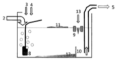
- FIG. 4 is a perspective view showing a pit for carrying out the method of Example 1.
- FIG. It is a conceptual diagram when the pit shown in FIG. 1 is seen from the side.
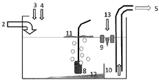
- 5 is a perspective view showing a pit for carrying out the method of Example 2.
- FIG. It is a conceptual diagram when the pit shown in FIG. 3 is seen from the side.
- 6 is a conceptual view of a pit for carrying out the method of Comparative Example 1 when viewed from the side.
- the wet coating booth circulating water treatment device of the present invention includes a discharge path (hereinafter, also referred to as a discharge pipe) for flowing circulating water from the wet coating booth toward the pit, a pit, a micro-nano bubble generator, and a pit. It has a supply path (hereinafter, also referred to as a supply pipe) for flowing circulating water from the surface to the wet coating booth.
- the outlet of the discharge passage is provided at or near one end of the pit, and the inlet of the supply passage is provided at or near the other end of the pit.
- the edge of the pit means at least one of two opposite sides of the rectangle in the rectangular pit, and at least one of the edge of the center well (inner circumference) and at least one of the outer edges in the circular pit. Means a place.
- the vicinity of the edge is a portion within the range recognized as the edge of the pit by those skilled in the art in consideration of the size of equipment required for actual operation.
- rectangular pits are preferably used.
- Examples of the wet coating booth to which the apparatus and method for treating the circulating water of the wet coating booth of the present invention are applicable include, for example, a water plate type (water film type) coating booth and a shower for collecting surplus paint by water film-shaped circulating water.
- shower paint booth that collects excess paint with water-like circulating water
- water film/shower paint booth combining water film type and shower type
- surplus paint separated by centrifugal force in the swirl chamber Venturi-type painting booths that collect in circulating water are included.
- Circulating water (untreated circulating water) containing excess paint and water obtained by collecting excess paint in the wet coating booth flows through the discharge passage from the wet coating booth toward the pit, If there is a distance from the circulating water accumulated in the pit, it moves from the outlet of the discharge path toward the circulating water accumulated in the pit, and the circulating water flowing in the pit and from the outlet of the discharge path is in the pit. It mixes with the circulating water that has accumulated in, and then temporarily stays in the pit. While the circulating water stays in the pit, excess paint is removed from the circulating water and the circulating water is clarified. The treated circulating water then flows from the pit to the wet coating booth in the supply channel and is reused for collecting excess paint in the wet coating booth.
- the residence time of the circulating water in the pit is not particularly limited, but is, for example, 2 to 5 minutes.
- the pit is not particularly limited depending on its shape, but a pit having a rectangular parallelepiped-shaped storage space is preferably used.
- the supply port of the untreated circulating water to the pit that is, the outlet of the discharge path, is the outlet of the treated circulating water from the pit, that is, the supply. It is preferable to install it at a position as far as possible from the entrance of the road.
- supply ports for untreated circulating water to the pit and outlets for treated circulating water from the pit can be provided at substantially both ends of the diagonal line of the rectangular parallelepiped storage space.
- a generator As a micro/nano bubble generator, a generator (a collapse method) that uses a sudden pressure change generated by ultrasonic waves, shock waves, etc., a disturbance generated by a Venturi tube, a high-speed swirling rotor, etc. in a state where gas and liquid are mixed
- a generator of a method that divides gas into air bubbles by a flow (a shear method)
- a generator of a method that combines a crushing method and a shear method
- a gas that is supplied to a cylinder by mixing and compressing bubbles
- the micro/nano bubble discharge port of the micro/nano bubble generator is a place where the circulating water flows in the discharge passage, and the circulating water is present in the space between the outlet of the discharge passage and the circulating water collected in the pit. It is installed in at least one selected from the group consisting of a place where it flows and a place where the circulating water discharged from the outlet of the discharge channel in the pit and mixed with the circulating water collected in the pit.
- the location of the micro-nano bubble discharge port of the micro-nano bubble generator is preferably a location where the shear rate generated by the flow of circulating water is 0.5 to 50 s -1 and is preferably 2 to 50 s -1. Is more preferable.
- Micro-nano bubbles are added to at least one selected from among the circulating water having a shear rate of 0.5 to 50 s ⁇ 1 , and more preferably to the circulating water having a shear rate of 2 to 50 s ⁇ 1. Then, the paint floating sludge is formed.
- the amount of micro-nano bubbles added to such circulating water is preferably 50% or more, more preferably 60% or more, still more preferably 70% or more, based on 100% of the total amount of micro-nano bubbles added.
- the shear rate is preferably less than 2s -1 in a pit, and more preferably in the circulating water flowing at less than 0.5 s -1, a portion of the micro-nano bubbles may be added.
- the amount of micro-nano bubbles added to the circulating water accumulated in such a pit or flowing at a low shear rate is preferably 50% or less, more preferably 50% or less, based on 100% of the total amount of micro-nano bubbles added. It is 40% or less, more preferably 30% or less.
- the average diameter of micro-nano bubbles when added to circulating water is preferably 100 ⁇ m or less, more preferably 70 ⁇ m or less, still more preferably 50 ⁇ m or less.
- the lower limit of the average diameter of the micro-nano bubbles when added to circulating water is not particularly limited, but is preferably 0.1 ⁇ m, more preferably 0.5 ⁇ m, and even more preferably 1 ⁇ m.
- water micro-nano bubble water obtained by forcibly dissolving a gas by pressurization is prepared. This micro-nano bubble water generates micro-nano bubbles in the circulating water due to a rapid decompression when it is added to the circulating water.
- the total amount of micro-nano bubbles added is preferably 0.005 to 0.30 g, and more preferably 0.05 to 0.15 g, relative to 1 g of excess paint (solid content). Excess paint flocs can be levitated by adding micro-nano bubbles.
- phenol resin-containing solution a phenol resin solution or dispersion
- low molecular weight cationic polymer solution or dispersion a low molecular weight cationic polymer solution or dispersion
- a liquid containing a low molecular weight cationic polymer a tackifier
- organic coagulant an inorganic coagulant
- pH adjusting agent a pH adjusting agent
- other water treatment agents within a range that does not impair the effects of the present invention.
- These water treatment agents are used from the circulating water flowing from the wet coating booth toward the pit, the circulating water flowing into the pit and mixing with the circulating water accumulated in the pit, the circulating water accumulated in the pit, and the circulating water accumulated in the pit. It can be added to at least one selected from the group consisting of circulating water flowing toward the wet coating booth.
- the phenolic resin solution or dispersion is obtained by dissolving or dispersing the phenolic resin in a solvent or dispersion medium having a high affinity with water.
- the phenol resin is a condensate of phenols and aldehydes or a modified product thereof, and is a product before cross-linking and curing.
- Specific examples of the phenol resin include a condensate of phenol and formaldehyde, a condensate of cresol and formaldehyde, and a condensate of xylenol and formaldehyde.
- the modified product include an alkyl-modified phenol resin and polyvinyl phenol. These phenolic resins may be novolac type or resol type.
- the phenol resin is not particularly limited depending on the molecular weight and other physical properties, and can be appropriately selected and used from those generally used for treating wet water in a wet coating booth.
- the phenol resins may be used alone or in combination of two or more.
- the phenolic resin used in the present invention has a weight average molecular weight of preferably 10,000 or less, more preferably 7,000 or less.
- Examples of the solvent or dispersion medium that can be used in the phenolic resin-containing liquid include ketones such as acetone, esters such as methyl acetate, alcohols such as methanol, alkaline aqueous solutions, and amines. Of these solvents, aqueous alkali solutions are preferred.
- Examples of the alkaline aqueous solution include sodium hydroxide aqueous solution and potassium hydroxide aqueous solution.
- the concentration of the alkaline component of the substance obtained by dissolving or dispersing the phenol resin in the alkaline aqueous solution is preferably 1 to 25% by mass, and the concentration of the phenol resin is preferably 1 to 50% by mass.
- Phenolic resin-containing liquid can be added by circulating water flowing from the wet coating booth toward the pit, circulating water that flows into the pit and mixes with the circulating water accumulated in the pit, or from the pit toward the wet coating booth. It is preferable to perform this on the flowing circulating water.
- the amount of the phenol resin (solid content) added is preferably 1 mg or more, more preferably 5 mg or more, with respect to 1 L of circulating water, from the viewpoint of non-adhesiveness of the excess paint. From the viewpoint of suppressing excessive foaming and an increase in operating cost, the upper limit of the amount of the phenol resin (solid content) added is preferably 1000 mg, more preferably 200 mg with respect to 1 L of circulating water.
- the addition amount of the phenol resin (solid content) is preferably 0.1% by mass or more, and more preferably 0.5% by mass or more, with respect to the excess coating material (solid content). Further, the upper limit of the amount of the phenol resin (solid content) added is preferably 100% by mass, more preferably 10% by mass, based on the excess coating material (solid content).
- Phenolic resins are suitable for water treatment in circulating water with a large amount of surface foam dust trapped with an aqueous paint, or circulating water with an organic solvent paint having a surface potential of almost zero. By adding the phenolic resin-containing liquid, the adhesiveness of the excess paint in the circulating water can be reduced (non-adhesive).
- the low molecular weight cationic polymer solution or dispersion is obtained by dissolving or dispersing the low molecular weight cationic polymer in a solvent or dispersion medium having a high affinity with water.
- the low molecular weight cationic polymer used in the present invention has, for example, a weight average molecular weight of preferably 1,000 or more and 1 million or less, and more preferably 5,000 or more and 300,000 or less.
- low molecular weight cationic polymer examples include polyethyleneimine, cation-modified polyacrylamide, polyamine, polyamine sulfone, polyamide, polyalkylene polyamine, amine cross-linked polycondensate, dimethylaminoethyl polyacrylate, and dimethyldialylammonium chloride (DADMAC) polymer.
- DADMAC dimethyldialylammonium chloride
- Examples thereof include a polycondensate product with aldehyde and a polycondensate product with dicyandiamide and diethylenetriamine.
- Examples of the alkylamine in the polycondensate of alkylamine and epichlorohydrin include monomethylamine, monoethylamine, dimethylamine, and diethylamine.
- Examples of the aldehyde in the melamine-aldehyde condensate and the disiandiamide-aldehyde polycondensate include formaldehyde, acetaldehyde, propionaldehyde, and paraformaldehyde, which is a trimer of formaldehyde.
- the low molecular weight cationic polymer may be used alone or in combination of two or more.
- Examples of the solvent or dispersion medium that can be used in the low molecular weight cationic polymer-containing liquid include water, acetone, and methanol.
- the liquid containing low molecular weight cationic polymer is added to the circulating water flowing from the wet coating booth toward the pit, the circulating water flowing into the pit and mixed with the circulating water accumulated in the pit, or the wet coating booth from the pit. It is preferable to perform this on the circulating water flowing toward.
- the amount of the low molecular weight cationic polymer (solid content) added is preferably 0.1 to 100 mg, preferably 0.3 to 30 mg with respect to 1 L of circulating water.
- the addition amount of the low molecular weight cationic polymer (solid content) is preferably 10% by mass or less, and more preferably 2% by mass or less with respect to the excess coating material (solid content).
- the lower limit of the addition amount of the low molecular weight cationic polymer (solid content) is preferably 1% by mass, and more preferably 5% by mass with respect to the excess coating material (solid content).
- tack-free agent examples include carboxylic acid polymers, tannin compounds, tannin-based polymers, melamine formaldehyde condensates, melamine dicyandiamide condensates, linear cationic polyamines, sodium zincate, and alumina sol. it can.
- organic coagulant examples include sodium alginate; chitin / chitosan-based coagulant; TKF04 strain, biocoagulant such as BF04.
- aluminum-based coagulants such as aluminum sulfate (sulfuric acid band), polyaluminum chloride (PAC), aluminum chloride, basic aluminum chloride, pseudo-boehmite alumina sol (AlO(OH)); ferrous hydroxide, Iron salt-based coagulants such as ferrous sulfate, ferric chloride, polyferric sulfate, iron-silica inorganic polymer coagulants; zinc-based coagulants such as zinc chloride; activated silicic acid, polysilica iron coagulants, etc. Can be mentioned.
- aluminum-based coagulants such as aluminum sulfate (sulfuric acid band), polyaluminum chloride (PAC), aluminum chloride, basic aluminum chloride, pseudo-boehmite alumina sol (AlO(OH)); ferrous hydroxide, Iron salt-based coagulants such as ferrous sulfate, ferric chloride, polyferric sulfate, iron-silica inorganic polymer
- water-soluble alkali metal compounds such as sodium hydroxide, potassium hydroxide, sodium carbonate, potassium carbonate, sodium hydrogencarbonate, and potassium hydrogencarbonate; mineral acids such as hydrochloric acid, sulfuric acid, nitrate, and phosphoric acid; etc. Can be mentioned.
- All or part of the paint floating sludge formed as described above is removed from the circulating water. Removal of all or part of the paint floating sludge is preferably carried out by taking in surface water containing the paint floating sludge and water with a water intake device.
- a water intake device include a surface liquid discharge device such as a float weir and a float pump.
- the circulating water from which all or part of the paint floating sludge has been removed (treated circulating water) is supplied to the wet coating booth via the supply channel and reused to collect excess paint.
- treated circulating water In order to prevent slag, sludge, flocs, etc. from being taken out together with the circulating water, it is preferable to provide a weir, a filter, a net or the like at or near the outlet of the treated circulating water from the pit.
- the total amount of the added micro-nano bubbles is preferably 50% or more, more preferably 80% or more, still more preferably 90% or more, still more preferably 95% or more, especially from the discharge port of the micro-nano bubbles to the inlet of the supply passage.
- the amount of micro-nano bubbles contained in the treated circulating water at the inlet of the supply channel is preferably 50% or less, more preferably 20% or less, further preferably 9% or less, and further more preferably 100% or less of all the added micro-nano bubbles. It is preferably 5% or less, particularly preferably 1% or less.
- a polymer cationic polymer solution or a dispersion liquid (hereinafter, these may be collectively referred to as "high molecular weight cationic polymer-containing solution”) is added to the surface water containing the paint floating sludge and water. It is preferable to add.
- the paint floating sludge By adding the liquid containing the high molecular weight cationic polymer, the paint floating sludge can be aggregated to facilitate solid-liquid separation.
- the high molecular weight cationic polymer-containing liquid is obtained by dissolving the high molecular weight cationic polymer in a solvent having a high affinity for water or by dispersing the high concentration solution in a hydrophobic liquid (W/O type emulsion), etc. Is.
- the high molecular weight cationic polymer has, for example, a weight average molecular weight of preferably more than 1,000,000, more preferably 5,000,000 or more, further preferably 6,000,000 to 11,000,000.
- a polymer having a cationic structural unit derived from a quaternary ammonium salt of (meth)acrylic acid ester for example, acrylamide/[2-(acryloyloxy)ethyl]benzyldimethylammonium chloride/[2 -Polymer of (acryloyloxy) ethyl] trimethylammonium chloride, acrylamide / [3- (acryloyloxy) propyl] benzyldimethylammonium chloride / polymer of [2- (acryloyloxy) ethyl] trimethylammonium chloride, acrylamide / [2- (Acryloyloxy) ethyl] benzyldimethylammonium chloride / [3- (acryloyloxy) propyl] trimethylammonium chloride copolymer, acrylamide / [3- (acryloyloxy) propyl] benzyl
- the high molecular weight cationic polymer may be used alone or in combination of two or more.
- the amount of the polymer cationic polymer (solid content) added is preferably 0.1 to 10% by mass, more preferably 0.2 to 3% by mass, based on the surplus coating material (solid content).
- the amount of the high molecular weight cationic polymer added is, for example, preferably 0.001 to 1 meq / L, more preferably 0.002 to 0.5 meq / L, as a colloid equivalent value with respect to circulating water.
- high molecular weight cationic polymers can prevent the redispersion of flocs (paint floating sludge), and can also be used for filtration and / or dehydration treatments (such as sedimentation and centrifugation) that may be performed after pressure flotation. ) Can be improved in efficiency.
- the surface water comprising paint floating sludge and water to which a high molecular weight cationic polymer-containing liquid has been added is taken up by an intake device, and the intake liquid taken by the intake device is subjected to a floating treatment, preferably a pressure floating treatment. It is preferable to apply.
- a floating treatment preferably a pressure floating treatment. It is preferable to apply.
- the pressure levitation treatment is a treatment method for levitating suspended matter by injecting a supersaturated solution of air (pressurized) into a liquid containing suspended matter (normal pressure) to generate air bubbles. is there.
- the average diameter of the bubbles generated in the pressure flotation treatment is preferably 120 ⁇ m or less, more preferably 30 ⁇ m or more and 120 ⁇ m or less.
- the average diameter of the bubbles generated in the pressure levitation treatment is preferably larger than the average diameter of the above-mentioned micro-nano bubbles.
- anionic polymer-containing solution is a liquid (W/O type emulsion) or the like in which the anionic polymer is dissolved in a solvent having a high affinity for water or the high concentration dissolved liquid is dispersed in a hydrophobic solvent.
- anionic polymer include sodium polyacrylate, sodium polyacrylate derivative, polyacrylamide partially hydrolyzed, partially sulfomethylated polyacrylamide, poly (2-acrylamide) -2-methylpropane sulfate and the like. it can.
- the anionic polymer may be used alone or in combination of two or more.
- the anionic polymer preferably has a degree of anionization of 10 to 30 mol%.
- the weight average molecular weight of the anionic polymer is preferably more than 1 million, more preferably 5 million or more, still more preferably 8 million to 15 million.
- the addition amount of the anionic polymer (solid content) is preferably 0.1 to 10% by mass, and more preferably 0.2 to 3% by mass with respect to the excess coating material (solid content).
- amphoteric polymer-containing liquid an amphoteric polymer solution or dispersion
- amphoteric polymer-containing liquid can be added to the water solution within a range that does not impair the effects of the present invention.
- the amphoteric polymer-containing liquid is a solution in which the amphoteric polymer is dissolved in a solvent having a high affinity for water or a high-concentration solution is dispersed in a hydrophobic solvent (W / O type emulsion) or the like.
- W / O type emulsion hydrophobic solvent
- the amphoteric polymer include a copolymer of (meth) acrylamide, quaternary ammonium alkyl (meth) acrylate, and sodium (meth) acrylate.
- the anion/cation molar ratio of the amphoteric polymer is preferably 0.2 to 2.0.
- the weight average molecular weight of the amphoteric polymer is preferably more than 1 million, more preferably 5 million or more, still more preferably 8 million to 10 million.
- the amount of the amphoteric polymer (solid content) added is preferably 0.1 to 10% by mass, more preferably 0.2 to 3% by mass, based on the excess coating material (solid content).
- the water intake liquid that has been subjected to the pressurized flotation treatment can be subjected to a filtration treatment and / or a dehydration treatment.
- a filtration treatment wedge wire screens, rotary screens, bar screens, flexible container bags and the like can be used.
- a dehydration treatment a cyclone, a centrifuge, a pressure filtration device or the like can be used. The sludge removed can be incinerated, landfilled, or composted.
- Comparative Example 1 At the wet coating booth, automobile parts were spray coated with organic solvent paint. During that time, 77 kg-dry / day of surplus paint was collected with circulating water (total amount of about 200 m 3 and circulation speed of about 30 m 3 / min). The circulating water that collected the excess paint was retained in the pit.
- Four shear-type micro-nano bubble generators were installed at the bottom of the pit in the range from the center of the pit to the position where the float pump was installed (shear velocity of 0.1 s ⁇ 1 ), and the air volume per unit was 7 l/min. Micro/nano bubbles were supplied to the circulating water retained in the pit.
- a 28% alkaline aqueous solution of phenolic resin is contained in a ratio of 5% by weight (solid content) to the excess paint (solid content) and a cationic quaternary with a weight average molecular weight of 100,000.
- a 50% solution of salt polyamine was added at a ratio of 0.45% by weight (solid content) to the excess paint (solid content).
- Surface water containing paint floating sludge was extracted from the pit by a float pump.
- a 40% acrylic acid-based cationic polymer solution having a weight average molecular weight of 7 million was added to the extracted surface water at a ratio of 0.1% by weight (solid content) to the excess paint (solid content), and it was float-separated.
- the liquid containing the paint floating sludge (slag) separated by the floating separation device was transferred to a flexible container bag and subjected to gravity filtration.
- the sludge recovery rate was 65% (sludge moisture content 74%, specific gravity 0.87).
- the turbidity of the circulating water after the treatment was 52.
- Example 1 Install four shearing type micro/nano bubble generators near the place in the pit where the circulating water flowing out from the outlet of the discharge pipe is mixed with the circulating water accumulated in the pit (flow at a shear rate of 20 s -1 ) Was changed, and the circulating water was treated in the same manner as in Comparative Example 1.
- the sludge recovery rate was 100% (sludge moisture content 68%, specific gravity 0.83).
- the turbidity of the circulating water after the treatment was 10.
- Example 2 Instead of four micro/nano bubble generators, a micro/nano bubble generator is installed at a place where circulating water flows in the discharge pipe (flow at a shear rate of 15 s ⁇ 1 ) and a pressure/dissolution type micro/nano bubble generator is used.
- a micro/nano bubble generator was installed at a place where circulating water flows in the discharge pipe (flow at a shear rate of 15 s ⁇ 1 ) and a pressure/dissolution type micro/nano bubble generator is used.
- the sludge recovery rate was 100% (sludge moisture content 67%, specific gravity 0.83).
- the turbidity of the circulating water after the treatment was 8.
- Comparative example 2 Instead of adding a 28% alkaline aqueous solution of a phenolic resin and a 50% solution of a cationic quaternary salt polyamine, a basic aluminum chloride solution (containing 12.2% as Al) was added in an amount of 3% by weight (based on solid content) with respect to the excess coating (solid content). Except that the pH adjuster aqueous solution (containing 22.8% of potassium carbonate and potassium hydroxide) was added at a ratio of 6% by weight (solid content) to the surplus paint (solid content). The circulating water was treated in the same manner as in Comparative Example 1. The sludge recovery rate was 59% (sludge moisture content 79%, specific gravity 0.87). The turbidity of the circulating water after the treatment was 48.
- Example 3 Same as Comparative Example 2 except that the location of the four shearing type micro/nano bubble generators was changed to a location near the location in the pit where the circulating water fell from the outlet of the discharge pipe and mixed with the circulating water accumulated in the pit.
- the circulating water was treated by the method.
- the sludge recovery rate was 85% (sludge moisture content 77%, specific gravity 0.87).
- the turbidity of the circulating water after the treatment was 40.
- Example 4 Instead of four shear type micro/nano bubble generators, a micro/nano bubble discharge port is installed in a place where circulating water flows in the discharge pipe, and micro/nano bubble water is prepared using a pressure dissolution type micro/nano bubble generator, The circulating water was treated in the same manner as in Comparative Example 2 except that micro-nano bubble water was supplied to the circulating water at 42 l / min from the outlet. The sludge recovery rate was 88% (sludge moisture content 76%, specific gravity 0.85). The turbidity of the circulating water after the treatment was 18.
- the surplus paint collected in the wet coating booth is highly tacky and non-adhesive and can be easily removed to the paint floating sludge (flock, slag) with high efficiency. It can be converted to reduce the amount of paint sludge accumulated in pits and the like. Then, the clarity of the circulating water returned to the wet coating booth can be stabilized.
Landscapes
- Life Sciences & Earth Sciences (AREA)
- Hydrology & Water Resources (AREA)
- Engineering & Computer Science (AREA)
- Environmental & Geological Engineering (AREA)
- Water Supply & Treatment (AREA)
- Chemical & Material Sciences (AREA)
- Organic Chemistry (AREA)
- Separation Of Suspended Particles By Flocculating Agents (AREA)
- Physical Water Treatments (AREA)
- Details Or Accessories Of Spraying Plant Or Apparatus (AREA)
Abstract
湿式塗装ブースからピットの一方の端若しくはその近辺に向かって流れている循環水、およびピットの一方の端若しくはその近辺に流れ込んでピット内に溜まった循環水と混ざり合っている循環水からなる群から選ばれる少なくともひとつに、マイクロナノバブルを添加して、塗料浮上スラッジを形成させ、循環水から塗料浮上スラッジの全部若しくは一部を除去し、次いで循環水をピットの他方の端若しくはその近辺から湿式塗装ブースに戻すことを含む、湿式塗装ブース循環水の処理方法。
Description
本発明は、湿式塗装ブース循環水の処理装置および処理方法に関する。より詳細に、本発明は、湿式塗装ブースで回収した余剰塗料を、不粘着性で且つ除去しやすい塗料浮上スラッジに高効率で変換して、ピットなどに堆積する塗料汚泥(スラッジ)の量を減らすことができる、湿式塗装ブース循環水の処理装置および処理方法に関する。
湿式塗装ブースにおいて塗着しなかった余剰塗料を循環水で捕集する。次いで循環水に捕集された余剰塗料を除去し、余剰塗料の除去された循環水を湿式塗装ブースで再使用する。そのために、湿式塗装ブース循環水に捕集された余剰塗料を除去する方法が種々提案されている。
例えば、特許文献1は、塗料を塗着しようとする被塗装物を上方に位置させ、その下方に捕集液を張った捕集槽を備えた塗装ブースにおいて、捕集槽内にエアレータを備え、該エアレータの噴出口を略水平方向に向けて設置したことを特徴とする塗装ブースの汚水浄化システムを開示している。
特許文献2は、湿式塗装ブース循環水に塗料ミストが取り込まれてなる塗料滓を、アルカリイオン水性洗浄剤固有のきめ細かな気泡を湿式塗装ブースのベンチュリーの機能によって超微粒子化した気泡で溶剤と不粘着化した塗料クズとに個別に気泡分離させて液面へと浮上分離浄化する方法を開示している。
特許文献3は、マイクロバブル発生手段で発生させたマイクロバブルを、塗装ブースの塗料スラッジ処理槽内の塗装ブース循環水中に吐出し、塗料スラッジ処理槽から導いたマイクロバブルが混入した塗装ブース循環水を、塗装ブースの排気ダクト内で噴霧して、塗装ブース排気中の塗料ミストに接触させることを特徴とするマイクロバブルを使用した塗装ブースの塗料ミスト除去方法を開示している。
特許文献4は、鏡筒1内の上部に旋回用ファン4を配置し、鏡筒内へと塗装ミスト流を下方から吸い込み、マイクロバブルを発生するノズル2を下方に向けて配置し、ノズルからフィルム状に拡散する水微粒子群と塗装ミスト上昇流の混流により、旋回領域を形成し、この領域内を浮遊するマイクロバブルを含んだ水微粒子群に揮発性有機化合物や塗装ミストを吸着・酸化処理する、揮発性有機化合物・塗装ミスト除去装置を開示している。
水性塗料スラッジや親水性不粘着化剤で処理された塗料スラッジは強い親水性である。一方、マイクロバブルは疎水性である。そのため、マイクロバブルはスラッジに付着し難く、浮上性の向上効果が十分に発揮されず、循環水の清澄性が安定しないことがある。
本発明の目的は、マイクロナノバブルを利用した湿式塗装ブース循環水の処理装置および処理方法を提供することである。
本発明の目的は、マイクロナノバブルを利用した湿式塗装ブース循環水の処理装置および処理方法を提供することである。
上記目的を達成するために検討した結果、以下の形態を包含する本発明を完成するに至った。
〔1〕 湿式塗装ブースからピットに向かって循環水を流すための排出路、ピット、マイクロナノバブル発生装置、およびピットから湿式塗装ブースに向かって循環水を流すための供給路を有し、
排出路の出口が、ピットの一方の端若しくはその近辺に設けられており、
供給路の入口が、ピットの他方の端若しくはその近辺に設けられており、
マイクロナノバブル発生装置のマイクロナノバブル吐出口が、排出路内で循環水が流れる場所、排出路の出口とピット内に溜まった循環水との間で循環水が流れる場所、およびピット内で且つ排出路の出口から出た循環水がピット内に溜まった循環水と混ざり合う場所からなる群から選ばれる少なくともひとつに、設置されている、
湿式塗装ブース循環水の処理装置。
排出路の出口が、ピットの一方の端若しくはその近辺に設けられており、
供給路の入口が、ピットの他方の端若しくはその近辺に設けられており、
マイクロナノバブル発生装置のマイクロナノバブル吐出口が、排出路内で循環水が流れる場所、排出路の出口とピット内に溜まった循環水との間で循環水が流れる場所、およびピット内で且つ排出路の出口から出た循環水がピット内に溜まった循環水と混ざり合う場所からなる群から選ばれる少なくともひとつに、設置されている、
湿式塗装ブース循環水の処理装置。
〔2〕 マイクロナノバブル発生装置のマイクロナノバブル吐出口の設置場所は、循環水の流れによって生じるせん断速度が0.5~50s-1となる場所である、〔1〕に記載の装置。
〔3〕 マイクロナノバブル発生装置が、加圧溶解式である、〔1〕または〔2〕に記載の湿式塗装ブース循環水の処理装置。
〔4〕 ピット内で且つ供給路の入口に近い側に取水装置をさらに有する、〔1〕~〔3〕のいずれかひとつに記載の処理装置。
〔3〕 マイクロナノバブル発生装置が、加圧溶解式である、〔1〕または〔2〕に記載の湿式塗装ブース循環水の処理装置。
〔4〕 ピット内で且つ供給路の入口に近い側に取水装置をさらに有する、〔1〕~〔3〕のいずれかひとつに記載の処理装置。
〔5〕 湿式塗装ブースからピットの一方の端若しくはその近辺に向かって流れている循環水、およびピットの一方の端若しくはその近辺に流れ込んでピット内に溜まった循環水と混ざり合っている循環水からなる群から選ばれる少なくともひとつに、マイクロナノバブルを添加して、塗料浮上スラッジを形成させ、
循環水から塗料浮上スラッジの全部若しくは一部を除去し、次いで
循環水をピットの他方の端若しくはその近辺から湿式塗装ブースに戻す
ことを含む、湿式塗装ブース循環水の処理方法。
循環水から塗料浮上スラッジの全部若しくは一部を除去し、次いで
循環水をピットの他方の端若しくはその近辺から湿式塗装ブースに戻す
ことを含む、湿式塗装ブース循環水の処理方法。
〔6〕 マイクロナノバブルの添加される循環水は、せん断速度が0.5~50s-1で流れている、〔5〕に記載の処理方法。
〔7〕 循環水に添加されたときのマイクロナノバブルの平均直径が100μm以下である、〔5〕または〔6〕に記載の処理方法。
〔7〕 循環水に添加されたときのマイクロナノバブルの平均直径が100μm以下である、〔5〕または〔6〕に記載の処理方法。
本発明の湿式塗装ブース循環水の処理装置および処理方法によれば、湿式塗装ブースで回収した余剰塗料が親水性であるか疎水性であるかに関わらず、該余剰塗料を不粘着性で且つ除去しやすい塗料浮上スラッジ(フロック、スラグ)に高効率で変換して、ピットなどに堆積する塗料汚泥(スラッジ)の量を減らすことができる。そして、湿式塗装ブースに返送する循環水の清澄性を安定させることができる。
本発明の湿式塗装ブース循環水の処理装置は、湿式塗装ブースからピットに向かって循環水を流すための排出路(以下、排出管ということもある。)、ピット、マイクロナノバブル発生装置、およびピットから湿式塗装ブースに向かって循環水を流すための供給路(以下、供給管ということもある。)を有する。排出路の出口が、ピットの一方の端若しくはその近辺に設けられており、供給路の入口が、ピットの他方の端若しくはその近辺に設けられている。なお、ピットの端とは、長方形ピットにおいては長方形の対向する二つの辺の少なくとも一カ所を意味し、円形ピットにおいてはセンターウエル(内周)の縁の少なくとも一カ所と外周の縁の少なくとも一カ所を意味する。端の近辺とは、実際の運用上必要な設備などの大きさなどを考慮し、当業者がピットの端と認識する範囲の箇所である。本発明においては長方形ピットが好ましく用いられる。
本発明の湿式塗装ブース循環水の処理装置および処理方法を適用可能な湿式塗装ブースとしては、例えば、水膜状の循環水により余剰塗料を捕集する水流板式(水膜式)塗装ブース、シャワー状の循環水により余剰塗料を捕集するシャワー式塗装ブース、水膜式とシャワー式とを組み合わせた水膜・シャワー式塗装ブース、渦巻室における遠心力により分離された余剰塗料を水膜状の循環水に捕集するベンチュリー式塗装ブース等が挙げられる。
湿式塗装ブースにおける余剰塗料の捕集によって得られる、余剰塗料と水とを含んでなる循環水(未処理循環水)は、湿式塗装ブースからピットに向かって排出路内を流れ、排出路出口とピット内に溜まった循環水との間に距離がある場合は排出路の出口からピット内に溜まった循環水に向かって移動し、ピット内で且つ排出路の出口から流れ出た循環水がピット内に溜まった循環水と混ざり合い、次いでピットに一時的に滞留する。循環水がピットに滞留している間に循環水から余剰塗料を取り除き、循環水を清澄化処理する。次いで処理済循環水は、ピットから湿式塗装ブースに向かって供給路内を流れ、湿式塗装ブースにおける余剰塗料の捕集に再使用される。ピットにおける循環水の滞留時間は、特に制限されないが、例えば、2~5分間である。
ピットは、その形状によって特に限定されないが、好ましくは直方体形状の貯留スペースを有するものが用いられる。そして、未処理循環水が処理済循環水と混ざり難くするために、ピットへの未処理循環水の供給口、すなわち、排出路の出口は、ピットからの処理済循環水の抜出口、すなわち供給路の入口とできるだけ離れた位置になるように、設置することが好ましい。例えば、図1に示すように、ピットへの未処理循環水の供給口とピットからの処理済循環水の抜出口とを直方体形状の貯留スペースの対角線のほぼ両端に設けることができる。
ピットは、その形状によって特に限定されないが、好ましくは直方体形状の貯留スペースを有するものが用いられる。そして、未処理循環水が処理済循環水と混ざり難くするために、ピットへの未処理循環水の供給口、すなわち、排出路の出口は、ピットからの処理済循環水の抜出口、すなわち供給路の入口とできるだけ離れた位置になるように、設置することが好ましい。例えば、図1に示すように、ピットへの未処理循環水の供給口とピットからの処理済循環水の抜出口とを直方体形状の貯留スペースの対角線のほぼ両端に設けることができる。
マイクロナノバブル発生装置としては、超音波、衝撃波等により発生する急激な圧力変化を利用する方式(圧壊方式)の発生装置、気体と液体が混合した状態でベンチュリー管、高速旋回ロータなどにより発生する乱流によって気体を千切る様にして気泡化する方式(せん断方式)の発生装置、圧壊方式とせん断方式とを組み合わせた方式の発生装置、筒に供給される気体と液体とを混合圧縮して気泡を含む液を得、これを気泡拡散孔に通して外に放出する方式(特開2001-104764号公報など参照)の発生装置、コンプレッサー等による加圧によって液中へ強制的に気体を溶解させ、その液体を急激に減圧して気体を放出させる方式(加圧溶解式)の発生装置などを挙げることができる。これらのうち、加圧溶解式の発生装置が好ましい。
本発明の処理装置においては、マイクロナノバブル発生装置のマイクロナノバブル吐出口が、排出路内で循環水が流れる場所、排出路の出口とピット内に溜まった循環水との間の空間で循環水が流れる場所、およびピット内で且つ排出路の出口から出た循環水がピット内に溜まった循環水と混ざり合う場所からなる群から選ばれる少なくともひとつに、設置される。マイクロナノバブル発生装置のマイクロナノバブル吐出口の設置場所は、循環水の流れによって生じるせん断速度が0.5~50s-1となる場所であることが好ましく、2~50s-1となる場所であることがより好ましい。このような場所にマイクロナノバブル吐出口を設置して、湿式塗装ブースからピットに向かって流れている循環水、およびピットに流れ込んでピット内に溜まった循環水と混ざり合っている循環水からなる群から選ばれる少なくともひとつに、好ましくはせん断速度が0.5~50s-1で流れている循環水に、より好ましくはせん断速度が2~50s-1で流れている循環水に、マイクロナノバブルを添加して、塗料浮上スラッジを形成させる。このような循環水へのマイクロナノバブルの添加量は、添加した全マイクロナノバブルの量100%に対して、好ましくは50%以上、より好ましくは60%以上、さらに好ましくは70%以上である。このような循環水へのマイクロナノバブルの添加は、ピット内に溜まっている循環水へのマイクロナノバブルの添加に比べて、マイクロナノバブルと余剰塗料との接触機会が増え、余剰塗料へのマイクロナノバブルの付着効率が高まる。
ピット内に溜まっている循環水、ピット内にせん断速度好ましくは2s-1未満、より好ましくは0.5s-1未満で流れている循環水に、マイクロナノバブルの一部が添加されてもよい。このようなピット内に溜まっているまたは低せん断速度で流れている循環水へのマイクロナノバブルの添加量は、添加した全マイクロナノバブルの量100%に対して、好ましくは50%以下、より好ましくは40%以下、さらに好ましくは30%以下である。
ピット内に溜まっている循環水、ピット内にせん断速度好ましくは2s-1未満、より好ましくは0.5s-1未満で流れている循環水に、マイクロナノバブルの一部が添加されてもよい。このようなピット内に溜まっているまたは低せん断速度で流れている循環水へのマイクロナノバブルの添加量は、添加した全マイクロナノバブルの量100%に対して、好ましくは50%以下、より好ましくは40%以下、さらに好ましくは30%以下である。
循環水に添加されたときのマイクロナノバブルの平均直径は、好ましくは100μm以下、より好ましくは70μm以下、さらに好ましくは50μm以下である。循環水に添加されたときのマイクロナノバブルの平均直径の下限は、特に制限されないが、好ましくは0.1μm、より好ましくは0.5μm、さらに好ましくは1μmである。加圧溶解式の発生装置においては、加圧によって強制的に気体を溶解させてなる水(マイクロナノバブル水)が調製される。このマイクロナノバブル水は循環水に添加されたときの急激な減圧によって循環水中でマイクロナノバブルを発生する。
マイクロナノバブルの総添加量(空気供給量)は、余剰塗料(固形分)1gに対して、好ましくは0.005~0.30g、より好ましくは0.05~0.15gである。マイクロナノバブルの添加によって、余剰塗料フロックを浮上させることができる。
本発明においては、マイクロナノバブル以外に、フェノール樹脂溶液または分散液(以下 これらを併せて「フェノール樹脂含有液」と記すことがある。)、低分子カチオン性ポリマー溶液または分散液(以下 これらを併せて「低分子カチオン性ポリマー含有液」と記すことがある。)、不粘着化剤、有機凝結剤、無機凝結剤、pH調整剤などの水処理剤を、本発明の効果を阻害しない範囲で、循環水に添加することができる。これら水処理剤は、湿式塗装ブースからピットに向かって流れている循環水、ピットに流れ込んでピット内に溜まった循環水と混ざり合っている循環水、ピット内に溜まった循環水、およびピットから湿式塗装ブースに向かって流れている循環水からなる群から選ばれる少なくともひとつに添加することができる。
フェノール樹脂溶液又は分散液は、水との親和性の高い溶媒若しくは分散媒にフェノール樹脂を溶解若しくは分散させてなるものである。
フェノール樹脂は、フェノール類とアルデヒド類との縮合物またはこれの変性物であって、架橋硬化させる前の物である。フェノール樹脂の具体例としては、フェノールとホルムアルデヒドとの縮合物、クレゾールとホルムアルデヒドとの縮合物、キシレノールとホルムアルデヒドとの縮合物などを挙げることができる。変性物としては、アルキル変性フェノール樹脂、ポリビニルフェノールなどを挙げることができる。これらのフェノール樹脂はノボラック型であっても、レゾール型であってもよい。また、該フェノール樹脂は、分子量その他物性によって特に制限はなく、湿式塗装ブース循環水処理用として一般に使用されているものの中から適宜選択して使用することができる。フェノール樹脂は1種単独で若しくは2種以上を組み合わせて用いてもよい。本発明に用いられるフェノール樹脂は、重量平均分子量が、好ましくは10000以下、より好ましくは7000以下である。
フェノール樹脂は、フェノール類とアルデヒド類との縮合物またはこれの変性物であって、架橋硬化させる前の物である。フェノール樹脂の具体例としては、フェノールとホルムアルデヒドとの縮合物、クレゾールとホルムアルデヒドとの縮合物、キシレノールとホルムアルデヒドとの縮合物などを挙げることができる。変性物としては、アルキル変性フェノール樹脂、ポリビニルフェノールなどを挙げることができる。これらのフェノール樹脂はノボラック型であっても、レゾール型であってもよい。また、該フェノール樹脂は、分子量その他物性によって特に制限はなく、湿式塗装ブース循環水処理用として一般に使用されているものの中から適宜選択して使用することができる。フェノール樹脂は1種単独で若しくは2種以上を組み合わせて用いてもよい。本発明に用いられるフェノール樹脂は、重量平均分子量が、好ましくは10000以下、より好ましくは7000以下である。
フェノール樹脂含有液に使用され得る溶媒若しくは分散媒としては、アセトン等のケトン、酢酸メチル等のエステル、メタノール等のアルコール、アルカリ水溶液、アミン等を挙げることができる。これら溶媒のうち、アルカリ水溶液が好ましい。アルカリ水溶液としては、水酸化ナトリウム水溶液、水酸化カリウム水溶液などを挙げることができる。フェノール樹脂をアルカリ水溶液に溶解ないし分散させてなる物は、アルカリ成分の濃度が好ましくは1~25質量%であり、フェノール樹脂の濃度が好ましくは1~50質量%である。
フェノール樹脂含有液の添加は、湿式塗装ブースからピットに向かって流れている循環水、ピットに流れ込んでピット内に溜まった循環水と混ざり合っている循環水、またはピットから湿式塗装ブースに向かって流れている循環水に対して行うことが好ましい。
フェノール樹脂(固形分)の添加量は、余剰塗料の不粘着化の観点から、循環水1Lに対して、好ましくは1mg以上、より好ましくは5mg以上である。過度の発泡および運転コストの上昇を抑えるという観点から、フェノール樹脂(固形分)の添加量の上限は、循環水1Lに対して、好ましくは1000mg、より好ましくは200mgである。また、フェノール樹脂(固形分)の添加量は、余剰塗料(固形分)に対して、好ましくは0.1質量%以上、より好ましくは0.5質量%以上である。また、フェノール樹脂(固形分)の添加量の上限は、余剰塗料(固形分)に対して、好ましくは100質量%、より好ましくは10質量%である。フェノール樹脂は、水性塗料を捕捉した表面泡末の多い循環水、または表面電位がほとんどゼロの有機溶剤塗料を捕捉した循環水における、水処理に好適である。フェノール樹脂含有液の添加によって、循環水中の余剰塗料の粘着性を下げる(不粘着化する)こともできる。
フェノール樹脂(固形分)の添加量は、余剰塗料の不粘着化の観点から、循環水1Lに対して、好ましくは1mg以上、より好ましくは5mg以上である。過度の発泡および運転コストの上昇を抑えるという観点から、フェノール樹脂(固形分)の添加量の上限は、循環水1Lに対して、好ましくは1000mg、より好ましくは200mgである。また、フェノール樹脂(固形分)の添加量は、余剰塗料(固形分)に対して、好ましくは0.1質量%以上、より好ましくは0.5質量%以上である。また、フェノール樹脂(固形分)の添加量の上限は、余剰塗料(固形分)に対して、好ましくは100質量%、より好ましくは10質量%である。フェノール樹脂は、水性塗料を捕捉した表面泡末の多い循環水、または表面電位がほとんどゼロの有機溶剤塗料を捕捉した循環水における、水処理に好適である。フェノール樹脂含有液の添加によって、循環水中の余剰塗料の粘着性を下げる(不粘着化する)こともできる。
低分子カチオン性ポリマー溶液又は分散液は、水との親和性の高い溶媒若しくは分散媒に低分子カチオン性ポリマーを溶解ないし分散させてなるものである。本発明に用いられる低分子カチオン性ポリマーは、例えば、重量平均分子量が、好ましくは1千以上100万以下、より好ましくは5千以上30万以下である。
低分子カチオン性ポリマーとしては、ポリエチレンイミン、カチオン変性ポリアクリルアミド、ポリアミン、ポリアミンスルホン、ポリアミド、ポリアルキレンポリアミン、アミン架橋重縮合体、ポリアクリル酸ジメチルアミノエチル、ジメチルジアリルアンモニウムクロライド(DADMAC)重合物、アルキルアミンとエピクロルヒドリンとの重縮合物、アルキレンジクロライドとポリアルキレンポリアミンとの重縮合物、ジシアンジアミドとホルマリンとの重縮合物、DAM(ジメチルアミノエチルメタアクリレート)の酸塩又は四級アンモニウム塩のホモポリマー又はコポリマー、DAA(ジメチルアミノエチルアクリレート)の酸塩又は四級アンモニウム塩のホモポリマー又はコポリマー、ポリビニルアミジン、ジアリルジメチルアンモニウムクロライドとアクリルアミドとの共重合物、メラミンとアルデヒドとの重縮合物、ジシアンジアミドとアルデヒドとの重縮合物、ジシアンジアミドとジエチレントリアミンとの重縮合物などを挙げることができる。なお、アルキルアミンとエピクロロヒドリンの重縮合物におけるアルキルアミンとしては、モノメチルアミン、モノエチルアミン、ジメチルアミン、ジエチルアミンなどを挙げることができる。メラミン・アルデヒド縮合物およびジシアンジアミド・アルデヒド重縮合物におけるアルデヒドとしては、ホルムアルデヒド、アセトアルデヒド、プロピオンアルデヒド、ホルムアルデヒドの3量体であるパラホルムアルデヒドなどを挙げることができる。低分子カチオン性ポリマーは1種単独で若しくは2種以上を組み合わせて用いてもよい。
低分子カチオン性ポリマー含有液に使用され得る溶媒若しくは分散媒としては、水、アセトン、メタノールなどを挙げることができる。
低分子カチオン性ポリマー含有液の添加は、湿式塗装ブースからピットに向かって流れている循環水、ピットに流れ込んでピット内に溜まった循環水と混ざり合っている循環水、またはピットから湿式塗装ブースに向かって流れている循環水に対して行うことが好ましい。
低分子カチオン性ポリマー(固形分)の添加量は、循環水1Lに対して、好ましくは0.1~100mg、好ましくは0.3~30mgである。また、低分子カチオン性ポリマー(固形分)の添加量は、余剰塗料(固形分)に対して、好ましくは10質量%以下、より好ましくは2質量%以下である。低分子カチオン性ポリマー(固形分)の添加量の下限は、余剰塗料(固形分)に対して、好ましくは1質量%、より好ましくは5質量%である。
低分子カチオン性ポリマー含有液の添加によって、循環水中の余剰塗料の荷電を中和して微細なフロックを形成しやすくすることができる。
低分子カチオン性ポリマー(固形分)の添加量は、循環水1Lに対して、好ましくは0.1~100mg、好ましくは0.3~30mgである。また、低分子カチオン性ポリマー(固形分)の添加量は、余剰塗料(固形分)に対して、好ましくは10質量%以下、より好ましくは2質量%以下である。低分子カチオン性ポリマー(固形分)の添加量の下限は、余剰塗料(固形分)に対して、好ましくは1質量%、より好ましくは5質量%である。
低分子カチオン性ポリマー含有液の添加によって、循環水中の余剰塗料の荷電を中和して微細なフロックを形成しやすくすることができる。
不粘着化剤としては、カルボン酸系重合体、タンニン系化合物、タンニン基剤重合体、メラミンホルムアルデヒド縮合物、メラミンジシアンジアミド縮合物、直鎖型カチオン性ポリアミン、亜鉛酸ナトリウム、アルミナゾルなどを挙げることができる。
有機凝結剤としては、アルギン酸ソーダ;キチン・キトサン系凝結剤;TKF04株、BF04などのバイオ凝結剤などを挙げることができる。
無機凝結剤としては、硫酸アルミニウム(硫酸バンド)、ポリ塩化アルミニウム(PAC)、塩化アルミニウム、塩基性塩化アルミニウム、擬ベーマイトアルミナゾル(AlO(OH))などのアルミニウム系凝結剤;水酸化第一鉄、硫酸第一鉄、塩化第二鉄、ポリ硫酸第二鉄、鉄-シリカ無機高分子凝結剤などの鉄塩系凝結剤;塩化亜鉛などの亜鉛系凝結剤;活性ケイ酸、ポリシリカ鉄凝結剤などを挙げることができる。
pH調整剤としては、水酸化ナトリウム、水酸化カリウム、炭酸ナトリウム、炭酸カリウム、炭酸水素ナトリウム、炭酸水素カリウムなどの水溶性アルカリ金属化合物;塩酸、硫酸、硝酸、リン酸などの鉱酸;などを挙げることができる。
上記のようにして形成された塗料浮上スラッジの全部若しくは一部を循環水から除去する。
塗料浮上スラッジの全部若しくは一部の除去は、好ましくは、塗料浮上スラッジと水とを含んでなる表層水を取水装置にて取水することによって、行われる。取水装置としては、フロート堰、フロートポンプなどの表層液排出装置を挙げることができる。
塗料浮上スラッジの全部若しくは一部の除去は、好ましくは、塗料浮上スラッジと水とを含んでなる表層水を取水装置にて取水することによって、行われる。取水装置としては、フロート堰、フロートポンプなどの表層液排出装置を挙げることができる。
一方、塗料浮上スラッジの全部若しくは一部の除去された循環水(処理済循環水)を供給路を介して湿式塗装ブースに供給して、余剰塗料の捕集に再使用する。スラグ、スラッジ、フロックなどが循環水に同伴して抜き出され難くするために、ピットからの処理済循環水の抜出口またはその近傍には、堰、フィルタ、網などを設けることが好ましい。添加した全マイクロナノバブルは、マイクロナノバブル吐出口から供給路の入口までの間に、好ましくは50%以上、より好ましくは80%以上、さらに好ましくは90%以上、よりさらに好ましくは95%以上、特に好ましくは99%以上が浮上スラッジ形成のために消費されるかまたは循環水に溶け込み若しくは水面で破裂して消失する。供給路入口における処理済循環水に含まれるマイクロナノバブルの量は、添加した全マイクロナノバブル100%に対して、好ましくは50%以下、より好ましくは20%以下、さらに好ましくは9%以下、よりさらに好ましくは5%以下、特に好ましくは1%以下である。
本発明においては、塗料浮上スラッジと水とを含んでなる表層水に高分子カチオン性ポリマー溶液又は分散液(以下 これらを併せて「高分子量カチオン性ポリマー含有液」と記すことがある。)を添加することが好ましい。高分子カチオン性ポリマー含有液の添加によって、塗料浮上スラッジを凝集させ、固液分離を容易にすることができる。
高分子カチオン性ポリマー含有液は、水との親和性の高い溶媒に高分子カチオン性ポリマーを溶解ないしは当該高濃度の溶解液を疎水性液体に分散させてなるもの(W/O型エマルション)等である。高分子カチオン性ポリマーは、例えば、重量平均分子量が、好ましくは100万超、より好ましくは500万以上、さらに好ましくは600万~1,100万である。
高分子カチオン性ポリマーとしては、(メタ)アクリル酸エステルの第四級アンモニウム塩由来のカチオン性構造単位を有するポリマー(例えば、アクリルアミド/[2-(アクリロイルオキシ)エチル]ベンジルジメチルアンモニウムクロリド/[2-(アクリロイルオキシ)エチル]トリメチルアンモニウムクロリドの共重合体、アクリルアミド/[3-(アクリロイルオキシ)プロピル]ベンジルジメチルアンモニウムクロリド/[2-(アクリロイルオキシ)エチル]トリメチルアンモニウムクロリドの共重合体、アクリルアミド/[2-(アクリロイルオキシ)エチル]ベンジルジメチルアンモニウムクロリド/[3-(アクリロイルオキシ)プロピル]トリメチルアンモニウムクロリドの共重合体、アクリルアミド/[3-(アクリロイルオキシ)プロピル]ベンジルジメチルアンモニウムクロリド/[3-(アクリロイルオキシ)プロピル]トリメチルアンモニウムクロリドの共重合体など)、ポリアミノアルキルアクリレート、ポリアミノアルキルメタクリレート、ポリエチレンイミン、ハロゲン化ポリジアリルアンモニウム、キトサン、尿素-ホルマリン樹脂などを挙げることができる。高分子カチオン性ポリマーは、1種単独で若しくは2種以上を組み合わせて用いることができる。高分子カチオン性ポリマー(固形分)の添加量は、余剰塗料(固形分)に対して、好ましくは0.1~10質量%、より好ましくは0.2~3質量%である。高分子カチオン性ポリマーの添加量は、例えば、循環水に対するコロイド当量値として、好ましくは0.001~1meq/L、より好ましくは0.002~0.5meq/Lである。高分子カチオン性ポリマーの添加によって、フロック(塗料浮上スラッジ)の再分散を防止することができ、また、加圧浮上処理後に行うことがある濾過処理および/または脱水処理(沈降分離や遠心分離など)の効率を高めることができる。
高分子カチオン性ポリマーとしては、(メタ)アクリル酸エステルの第四級アンモニウム塩由来のカチオン性構造単位を有するポリマー(例えば、アクリルアミド/[2-(アクリロイルオキシ)エチル]ベンジルジメチルアンモニウムクロリド/[2-(アクリロイルオキシ)エチル]トリメチルアンモニウムクロリドの共重合体、アクリルアミド/[3-(アクリロイルオキシ)プロピル]ベンジルジメチルアンモニウムクロリド/[2-(アクリロイルオキシ)エチル]トリメチルアンモニウムクロリドの共重合体、アクリルアミド/[2-(アクリロイルオキシ)エチル]ベンジルジメチルアンモニウムクロリド/[3-(アクリロイルオキシ)プロピル]トリメチルアンモニウムクロリドの共重合体、アクリルアミド/[3-(アクリロイルオキシ)プロピル]ベンジルジメチルアンモニウムクロリド/[3-(アクリロイルオキシ)プロピル]トリメチルアンモニウムクロリドの共重合体など)、ポリアミノアルキルアクリレート、ポリアミノアルキルメタクリレート、ポリエチレンイミン、ハロゲン化ポリジアリルアンモニウム、キトサン、尿素-ホルマリン樹脂などを挙げることができる。高分子カチオン性ポリマーは、1種単独で若しくは2種以上を組み合わせて用いることができる。高分子カチオン性ポリマー(固形分)の添加量は、余剰塗料(固形分)に対して、好ましくは0.1~10質量%、より好ましくは0.2~3質量%である。高分子カチオン性ポリマーの添加量は、例えば、循環水に対するコロイド当量値として、好ましくは0.001~1meq/L、より好ましくは0.002~0.5meq/Lである。高分子カチオン性ポリマーの添加によって、フロック(塗料浮上スラッジ)の再分散を防止することができ、また、加圧浮上処理後に行うことがある濾過処理および/または脱水処理(沈降分離や遠心分離など)の効率を高めることができる。
高分子カチオン性ポリマー含有液の添加された塗料浮上スラッジと水とを含んでなる表層水は、取水装置によって取水され、取水装置で取水された取水液に、浮上処理、好ましくは加圧浮上処理を施すことが好ましい。
浮上処理を施すことによって、高分子カチオン性ポリマー含有液で凝集された塗料浮上スラッジを液面に浮上させることができる。なお、加圧浮上処理は、浮遊物を含む液(常圧)に、空気の過飽和溶液(加圧)を注入することによって、空気の気泡を発生させ、浮遊物を浮上させるための処理方法である。加圧浮上処理において発生する気泡の平均直径は、好ましくは120μm以下、より好ましくは30μm以上120μm以下である。加圧浮上処理において発生する気泡の平均直径は、前述のマイクロナノバブルの平均直径よりも大きいことが好ましい。
浮上処理を施すことによって、高分子カチオン性ポリマー含有液で凝集された塗料浮上スラッジを液面に浮上させることができる。なお、加圧浮上処理は、浮遊物を含む液(常圧)に、空気の過飽和溶液(加圧)を注入することによって、空気の気泡を発生させ、浮遊物を浮上させるための処理方法である。加圧浮上処理において発生する気泡の平均直径は、好ましくは120μm以下、より好ましくは30μm以上120μm以下である。加圧浮上処理において発生する気泡の平均直径は、前述のマイクロナノバブルの平均直径よりも大きいことが好ましい。
浮上処理を施す際に、アニオン性ポリマー溶液又は分散液(以下 これらを併せて「アニオン性ポリマー含有液」と記すことがある。)を取水液に添加することがさらに好ましい。アニオン性ポリマー含有液は、水との親和性の高い溶媒にアニオン性ポリマーを溶解ないしは当該高濃度の溶解液を疎水性溶媒に分散させてなるもの(W/O型エマルション)等である。
アニオン性ポリマーとしては、ポリアクリル酸ナトリウム、ポリアクリル酸ソーダ・アミド誘導体、ポリアクリルアミド部分加水分解物、部分スルホメチル化ポリアクリルアミド、ポリ(2-アクリルアミド)-2-メチルプロパン硫酸塩などを挙げることができる。アニオン性ポリマーは、1種単独で若しくは2種以上を組み合わせて用いることができる。アニオン性ポリマーはアニオン化度が10~30モル%であるものが好適である。アニオン性ポリマーの重量平均分子量は、好ましくは100万超、より好ましくは500万以上、さらに好ましくは800万~1500万である。アニオン性ポリマー(固形分)の添加量は、余剰塗料(固形分)に対して、好ましくは0.1~10質量%、より好ましくは0.2~3質量%である。
アニオン性ポリマーとしては、ポリアクリル酸ナトリウム、ポリアクリル酸ソーダ・アミド誘導体、ポリアクリルアミド部分加水分解物、部分スルホメチル化ポリアクリルアミド、ポリ(2-アクリルアミド)-2-メチルプロパン硫酸塩などを挙げることができる。アニオン性ポリマーは、1種単独で若しくは2種以上を組み合わせて用いることができる。アニオン性ポリマーはアニオン化度が10~30モル%であるものが好適である。アニオン性ポリマーの重量平均分子量は、好ましくは100万超、より好ましくは500万以上、さらに好ましくは800万~1500万である。アニオン性ポリマー(固形分)の添加量は、余剰塗料(固形分)に対して、好ましくは0.1~10質量%、より好ましくは0.2~3質量%である。
本発明においては、本発明の効果を阻害しない範囲で、両性ポリマー溶液又は分散液(以下 これらを併せて「両性ポリマー含有液」と記すことがある。)を取水液に添加することができる。両性ポリマー含有液は、水との親和性の高い溶媒に両性ポリマーを溶解ないし高濃度の溶解液を疎水性溶媒に分散させてなるもの(W/O型エマルション)等である。
両性ポリマーとしては(メタ)アクリルアミドと4級アンモニウムアルキル(メタ)アクリレートと(メタ)アクリル酸ナトリウムとの共重合体などを挙げることができる。両性ポリマーのアニオン/カチオンのモル比は0.2~2.0が好適である。両性ポリマーの重量平均分子量は、好ましくは100万超、より好ましくは500万以上、さらに好ましくは800万~1000万である。両性ポリマー(固形分)の添加量は、余剰塗料(固形分)に対して、好ましくは0.1~10質量%、より好ましくは0.2~3質量%である。
両性ポリマーとしては(メタ)アクリルアミドと4級アンモニウムアルキル(メタ)アクリレートと(メタ)アクリル酸ナトリウムとの共重合体などを挙げることができる。両性ポリマーのアニオン/カチオンのモル比は0.2~2.0が好適である。両性ポリマーの重量平均分子量は、好ましくは100万超、より好ましくは500万以上、さらに好ましくは800万~1000万である。両性ポリマー(固形分)の添加量は、余剰塗料(固形分)に対して、好ましくは0.1~10質量%、より好ましくは0.2~3質量%である。
加圧浮上処理の施された取水液に、濾過処理および/または脱水処理を施すことができる。濾過処理においては、ウェッジワイヤスクリーン、ロータリースクリーン、バースクリーン、フレキシブルコンテナバッグなどを用いることができる。
脱水処理においては、サイクロン、遠心分離機、加圧ろ過装置などを用いることができる。取り出されたスラッジは、焼却したり、埋め立て処分したり、コンポスト化したりすることができる。
脱水処理においては、サイクロン、遠心分離機、加圧ろ過装置などを用いることができる。取り出されたスラッジは、焼却したり、埋め立て処分したり、コンポスト化したりすることができる。
次に、実施例を示して、本発明をより具体的に説明する。但し、以下の実施例は本発明の一実施形態を示すに過ぎず、本発明を以下の実施例に限定するものでない。
比較例1
湿式塗装ブースにおいて、自動車部品を有機溶剤塗料でスプレー塗装を行った。その間、余剰塗料77kg-dry/日を循環水(総量約200m3、循環速度約30m3/分)で捕集した。余剰塗料を捕集した循環水をピットに滞留させた。ピットの中央部からフロートポンプ設置位置までの範囲(せん断速度0.1s-1の流れ)にせん断方式マイクロナノバブル発生装置4基をピットの底に設置し、1基当たり空気量7l/分で、ピットに滞留している循環水に、マイクロナノバブルを供給した。同時に、ピットに滞留している循環水に、フェノール樹脂28%アルカリ水溶液を余剰塗料(固形分)に対して5重量%(固形分)の割合で、且つ重量平均分子量10万のカチオン性4級塩ポリアミン50%溶液を余剰塗料(固形分)に対して0.45重量%(固形分)の割合で添加した。
フロートポンプにて、塗料浮上スラッジを含む表層水をピットから抜き出した。抜き出した表層水に、重量平均分子量700万のアクリル酸系カチオン性ポリマー40%溶液を余剰塗料(固形分)に対して0.1重量%(固形分)の割合で添加し、それを浮上分離装置に移送した。浮上分離装置で分離した塗料浮上スラッジ(スラグ)を含む液をフレキシブルコンテナバックに移し重力濾過を行った。スラッジ回収率は65%(スラッジ含水率74%、比重0.87)であった。処理後の循環水の濁度は52であった。
湿式塗装ブースにおいて、自動車部品を有機溶剤塗料でスプレー塗装を行った。その間、余剰塗料77kg-dry/日を循環水(総量約200m3、循環速度約30m3/分)で捕集した。余剰塗料を捕集した循環水をピットに滞留させた。ピットの中央部からフロートポンプ設置位置までの範囲(せん断速度0.1s-1の流れ)にせん断方式マイクロナノバブル発生装置4基をピットの底に設置し、1基当たり空気量7l/分で、ピットに滞留している循環水に、マイクロナノバブルを供給した。同時に、ピットに滞留している循環水に、フェノール樹脂28%アルカリ水溶液を余剰塗料(固形分)に対して5重量%(固形分)の割合で、且つ重量平均分子量10万のカチオン性4級塩ポリアミン50%溶液を余剰塗料(固形分)に対して0.45重量%(固形分)の割合で添加した。
フロートポンプにて、塗料浮上スラッジを含む表層水をピットから抜き出した。抜き出した表層水に、重量平均分子量700万のアクリル酸系カチオン性ポリマー40%溶液を余剰塗料(固形分)に対して0.1重量%(固形分)の割合で添加し、それを浮上分離装置に移送した。浮上分離装置で分離した塗料浮上スラッジ(スラグ)を含む液をフレキシブルコンテナバックに移し重力濾過を行った。スラッジ回収率は65%(スラッジ含水率74%、比重0.87)であった。処理後の循環水の濁度は52であった。
実施例1
せん断方式マイクロナノバブル発生装置4基の設置場所を、ピット内で且つ排出管の出口から流れ出た循環水がピット内に溜まった循環水と混ざり合っている場所の近辺(せん断速度20s-1の流れ)に変えた以外は、比較例1と同じ方法で、循環水を処理した。スラッジ回収率は100%(スラッジ含水率68%、比重0.83)であった。処理後の循環水の濁度は10であった。
せん断方式マイクロナノバブル発生装置4基の設置場所を、ピット内で且つ排出管の出口から流れ出た循環水がピット内に溜まった循環水と混ざり合っている場所の近辺(せん断速度20s-1の流れ)に変えた以外は、比較例1と同じ方法で、循環水を処理した。スラッジ回収率は100%(スラッジ含水率68%、比重0.83)であった。処理後の循環水の濁度は10であった。
実施例2
マイクロナノバブル発生装置4基の代わりに、マイクロナノバブル吐出口を排出管内で循環水が流れる場所(せん断速度15s-1の流れ)に設置し、加圧溶解式マイクロナノバブル発生装置を用いてマイクロナノバブル水を調製し、マイクロナノバブル吐出口からマイクロナノバブル水を42l/分にて循環水に供給した以外は、比較例1と同じ方法で、循環水を処理した。スラッジ回収率は100%(スラッジ含水率67%、比重0.83)であった。処理後の循環水の濁度は8であった。
マイクロナノバブル発生装置4基の代わりに、マイクロナノバブル吐出口を排出管内で循環水が流れる場所(せん断速度15s-1の流れ)に設置し、加圧溶解式マイクロナノバブル発生装置を用いてマイクロナノバブル水を調製し、マイクロナノバブル吐出口からマイクロナノバブル水を42l/分にて循環水に供給した以外は、比較例1と同じ方法で、循環水を処理した。スラッジ回収率は100%(スラッジ含水率67%、比重0.83)であった。処理後の循環水の濁度は8であった。
比較例2
フェノール樹脂28%アルカリ水溶液およびカチオン性4級塩ポリアミン50%溶液の添加の代わりに、塩基性塩化アルミニウム溶液(Alとして12.2%含有)を余剰塗料(固形分)に対して3重量%(固形分)の割合で、且つpH調整剤水溶液(炭酸カリウムと水酸化カリウムとを22.8%含有)を余剰塗料(固形分)に対して6重量%(固形分)の割合で添加した以外は、比較例1と同じ方法で、循環水を処理した。スラッジ回収率は59%(スラッジ含水率79%、比重0.87)であった。処理後の循環水の濁度は48であった。
フェノール樹脂28%アルカリ水溶液およびカチオン性4級塩ポリアミン50%溶液の添加の代わりに、塩基性塩化アルミニウム溶液(Alとして12.2%含有)を余剰塗料(固形分)に対して3重量%(固形分)の割合で、且つpH調整剤水溶液(炭酸カリウムと水酸化カリウムとを22.8%含有)を余剰塗料(固形分)に対して6重量%(固形分)の割合で添加した以外は、比較例1と同じ方法で、循環水を処理した。スラッジ回収率は59%(スラッジ含水率79%、比重0.87)であった。処理後の循環水の濁度は48であった。
実施例3
せん断方式マイクロナノバブル発生装置4基の設置場所を、ピット内で且つ排出管の出口から循環水が流れ落ちピット内に溜まった循環水と混じり合う場所の近辺に変えた以外は、比較例2と同じ方法で、循環水を処理した。スラッジ回収率は85%(スラッジ含水率77%、比重0.87)であった。処理後の循環水の濁度は40であった。
せん断方式マイクロナノバブル発生装置4基の設置場所を、ピット内で且つ排出管の出口から循環水が流れ落ちピット内に溜まった循環水と混じり合う場所の近辺に変えた以外は、比較例2と同じ方法で、循環水を処理した。スラッジ回収率は85%(スラッジ含水率77%、比重0.87)であった。処理後の循環水の濁度は40であった。
実施例4
せん断方式マイクロナノバブル発生装置4基の代わりに、マイクロナノバブル吐出口を排出管内で循環水が流れる場所に設置し、加圧溶解式マイクロナノバブル発生装置を用いてマイクロナノバブル水を調製し、マイクロナノバブル吐出口からマイクロナノバブル水を42l/分にて循環水に供給した以外は、比較例2と同じ方法で、循環水を処理した。スラッジ回収率は88%(スラッジ含水率76%、比重0.85)であった。処理後の循環水の濁度は18であった。
せん断方式マイクロナノバブル発生装置4基の代わりに、マイクロナノバブル吐出口を排出管内で循環水が流れる場所に設置し、加圧溶解式マイクロナノバブル発生装置を用いてマイクロナノバブル水を調製し、マイクロナノバブル吐出口からマイクロナノバブル水を42l/分にて循環水に供給した以外は、比較例2と同じ方法で、循環水を処理した。スラッジ回収率は88%(スラッジ含水率76%、比重0.85)であった。処理後の循環水の濁度は18であった。
以上の結果が示すとおり、本発明の処理方法(実施例)によれば、湿式塗装ブースで回収した余剰塗料を、不粘着性で且つ除去しやすい塗料浮上スラッジ(フロック、スラグ)に高効率で変換して、ピットなどに堆積する塗料汚泥(スラッジ)の量を減らすことができる。そして、湿式塗装ブースに返送する循環水の清澄性を安定させることができる。
2:塗装ブースからの未処理循環水
3:フェノール樹脂含有液または塩基性塩化アルミニウム溶液
4:低分子カチオン性ポリマー含有液またはpH調整剤水溶液
5:塗装ブースへの処理済循環水
6:取水液
7:マイクロナノバブル
8:マイクロナノバブル発生装置
9:取水装置(フローポンプ)
10:堰
11:塗料浮上スラッジ
12:塗料汚泥(スラッジ)
13:高分子カチオン性ポリマー含有液
14:空気
15:マイクロナノバブル水
3:フェノール樹脂含有液または塩基性塩化アルミニウム溶液
4:低分子カチオン性ポリマー含有液またはpH調整剤水溶液
5:塗装ブースへの処理済循環水
6:取水液
7:マイクロナノバブル
8:マイクロナノバブル発生装置
9:取水装置(フローポンプ)
10:堰
11:塗料浮上スラッジ
12:塗料汚泥(スラッジ)
13:高分子カチオン性ポリマー含有液
14:空気
15:マイクロナノバブル水
Claims (7)
- 湿式塗装ブースからピットに向かって循環水を流すための排出路、ピット、マイクロナノバブル発生装置、およびピットから湿式塗装ブースに向かって循環水を流すための供給路を有し、
排出路の出口が、ピットの一方の端若しくはその近辺に設けられており、
供給路の入口が、ピットの他方の端若しくはその近辺に設けられており、
マイクロナノバブル発生装置のマイクロナノバブル吐出口が、排出路内で循環水が流れる場所、排出路の出口とピット内に溜まった循環水との間で循環水が流れる場所、およびピット内で且つ排出路の出口から出た循環水がピット内に溜まった循環水と混ざり合う場所からなる群から選ばれる少なくともひとつに、設置されている、
湿式塗装ブース循環水の処理装置。 - マイクロナノバブル発生装置のマイクロナノバブル吐出口の設置場所は、循環水の流れによって生じるせん断速度が0.5~50s-1となる場所である、請求項1に記載の処理装置。
- マイクロナノバブル発生装置が、加圧溶解式である、請求項1または2に記載の処理装置。
- ピット内で且つ供給路の入口に近い側に取水装置をさらに有する、請求項1~3のいずれかひとつに記載の処理装置。
- 湿式塗装ブースからピットの一方の端若しくはその近辺に向かって流れている循環水、およびピットの一方の端若しくはその近辺に流れ込んでピット内に溜まった循環水と混ざり合っている循環水からなる群から選ばれる少なくともひとつに、マイクロナノバブルを添加して、塗料浮上スラッジを形成させ、次いで
循環水から塗料浮上スラッジの全部若しくは一部を除去し、次いで
循環水をピットの他方の端若しくはその近辺から湿式塗装ブースに戻す
ことを含む、湿式塗装ブース循環水の処理方法。 - マイクロナノバブルの添加される循環水は、せん断速度が0.5~50s-1で流れている、請求項5に記載の処理方法。
- 循環水に添加されたときのマイクロナノバブルの平均直径が100μm以下である、請求項5または6に記載の処理方法。
Priority Applications (1)
| Application Number | Priority Date | Filing Date | Title |
|---|---|---|---|
| CN202080018747.3A CN113557216A (zh) | 2019-03-05 | 2020-03-04 | 湿式涂装室循环水的处理装置以及处理方法 |
Applications Claiming Priority (2)
| Application Number | Priority Date | Filing Date | Title |
|---|---|---|---|
| JP2019039844A JP6891908B2 (ja) | 2019-03-05 | 2019-03-05 | 湿式塗装ブース循環水の処理装置および処理方法 |
| JP2019-039844 | 2019-03-05 |
Publications (1)
| Publication Number | Publication Date |
|---|---|
| WO2020179842A1 true WO2020179842A1 (ja) | 2020-09-10 |
Family
ID=72338164
Family Applications (1)
| Application Number | Title | Priority Date | Filing Date |
|---|---|---|---|
| PCT/JP2020/009250 Ceased WO2020179842A1 (ja) | 2019-03-05 | 2020-03-04 | 湿式塗装ブース循環水の処理装置および処理方法 |
Country Status (3)
| Country | Link |
|---|---|
| JP (1) | JP6891908B2 (ja) |
| CN (1) | CN113557216A (ja) |
| WO (1) | WO2020179842A1 (ja) |
Cited By (2)
| Publication number | Priority date | Publication date | Assignee | Title |
|---|---|---|---|---|
| WO2022018905A1 (ja) * | 2020-07-21 | 2022-01-27 | 栗田工業株式会社 | 湿式塗装ブース循環水の処理装置および処理方法 |
| JP2023000946A (ja) * | 2021-06-18 | 2023-01-04 | 栗田工業株式会社 | 湿式塗装ブース循環水の処理装置および処理方法 |
Families Citing this family (1)
| Publication number | Priority date | Publication date | Assignee | Title |
|---|---|---|---|---|
| CN114538816B (zh) * | 2022-03-26 | 2023-02-28 | 中建西部建设北方有限公司 | 一种微纳米气泡水及其制备方法和砂浆组合物 |
Citations (8)
| Publication number | Priority date | Publication date | Assignee | Title |
|---|---|---|---|---|
| JP2004074084A (ja) * | 2002-08-21 | 2004-03-11 | Aiensu:Kk | 塗装ブースの汚水浄化システム |
| JP2008119612A (ja) * | 2006-11-13 | 2008-05-29 | Taikisha Ltd | 分離処理槽 |
| JP2009269024A (ja) * | 2008-04-11 | 2009-11-19 | Mac Technical Systems Kk | 湿式塗装ブース循環水の気泡による浮上分離浄化方法 |
| WO2015182647A1 (ja) * | 2014-05-28 | 2015-12-03 | 武田薬品工業株式会社 | 抗菌水 |
| WO2016088857A1 (ja) * | 2014-12-04 | 2016-06-09 | Tsk株式会社 | 塗料残渣の捕集システムおよび塗料残渣の捕集方法 |
| JP2017100049A (ja) * | 2015-11-30 | 2017-06-08 | パーカーエンジニアリング株式会社 | マイクロバブルを使用した塗装ブースの塗料ミスト除去方法 |
| WO2017187646A1 (ja) * | 2016-04-29 | 2017-11-02 | 憲司 久木野 | 気泡の粒径分布を任意に調整できるナノサイズ気泡発生装置 |
| JP2019018173A (ja) * | 2017-07-20 | 2019-02-07 | パーカーエンジニアリング株式会社 | 塗装ブース循環水タンク |
Family Cites Families (6)
| Publication number | Priority date | Publication date | Assignee | Title |
|---|---|---|---|---|
| JP4069799B2 (ja) * | 2003-05-13 | 2008-04-02 | 栗田工業株式会社 | 湿式塗装ブース循環水の処理方法 |
| JP4697130B2 (ja) * | 2006-12-15 | 2011-06-08 | 栗田工業株式会社 | 湿式ブース循環水の処理方法 |
| JP4717837B2 (ja) * | 2007-01-18 | 2011-07-06 | 伯東株式会社 | ブース循環水の処理方法 |
| ES2802201T3 (es) * | 2014-07-23 | 2021-01-15 | Kurita Water Ind Ltd | Método de tratamiento para hacer circular agua de cabina de recubrimiento de tipo húmedo |
| JP2016140805A (ja) * | 2015-01-30 | 2016-08-08 | 栗田工業株式会社 | 湿式塗装ブース循環水の処理方法及び処理装置 |
| CN104310554B (zh) * | 2014-11-05 | 2017-02-15 | 扬州大学 | 微纳米气泡絮凝‑气浮工艺 |
-
2019
- 2019-03-05 JP JP2019039844A patent/JP6891908B2/ja active Active
-
2020
- 2020-03-04 CN CN202080018747.3A patent/CN113557216A/zh active Pending
- 2020-03-04 WO PCT/JP2020/009250 patent/WO2020179842A1/ja not_active Ceased
Patent Citations (8)
| Publication number | Priority date | Publication date | Assignee | Title |
|---|---|---|---|---|
| JP2004074084A (ja) * | 2002-08-21 | 2004-03-11 | Aiensu:Kk | 塗装ブースの汚水浄化システム |
| JP2008119612A (ja) * | 2006-11-13 | 2008-05-29 | Taikisha Ltd | 分離処理槽 |
| JP2009269024A (ja) * | 2008-04-11 | 2009-11-19 | Mac Technical Systems Kk | 湿式塗装ブース循環水の気泡による浮上分離浄化方法 |
| WO2015182647A1 (ja) * | 2014-05-28 | 2015-12-03 | 武田薬品工業株式会社 | 抗菌水 |
| WO2016088857A1 (ja) * | 2014-12-04 | 2016-06-09 | Tsk株式会社 | 塗料残渣の捕集システムおよび塗料残渣の捕集方法 |
| JP2017100049A (ja) * | 2015-11-30 | 2017-06-08 | パーカーエンジニアリング株式会社 | マイクロバブルを使用した塗装ブースの塗料ミスト除去方法 |
| WO2017187646A1 (ja) * | 2016-04-29 | 2017-11-02 | 憲司 久木野 | 気泡の粒径分布を任意に調整できるナノサイズ気泡発生装置 |
| JP2019018173A (ja) * | 2017-07-20 | 2019-02-07 | パーカーエンジニアリング株式会社 | 塗装ブース循環水タンク |
Cited By (4)
| Publication number | Priority date | Publication date | Assignee | Title |
|---|---|---|---|---|
| WO2022018905A1 (ja) * | 2020-07-21 | 2022-01-27 | 栗田工業株式会社 | 湿式塗装ブース循環水の処理装置および処理方法 |
| JP2022021176A (ja) * | 2020-07-21 | 2022-02-02 | 栗田工業株式会社 | 湿式塗装ブース循環水の処理装置および処理方法 |
| JP2023000946A (ja) * | 2021-06-18 | 2023-01-04 | 栗田工業株式会社 | 湿式塗装ブース循環水の処理装置および処理方法 |
| JP7707680B2 (ja) | 2021-06-18 | 2025-07-15 | 栗田工業株式会社 | 湿式塗装ブース循環水の処理装置および処理方法 |
Also Published As
| Publication number | Publication date |
|---|---|
| JP2020142177A (ja) | 2020-09-10 |
| CN113557216A (zh) | 2021-10-26 |
| JP6891908B2 (ja) | 2021-06-18 |
Similar Documents
| Publication | Publication Date | Title |
|---|---|---|
| JP6642616B2 (ja) | 湿式塗装ブース循環水の処理方法 | |
| JP7154991B2 (ja) | 湿式塗装ブース循環水の処理方法 | |
| WO2020179842A1 (ja) | 湿式塗装ブース循環水の処理装置および処理方法 | |
| WO2016013586A1 (ja) | 湿式塗装ブース循環水の処理方法及び処理装置 | |
| JP6923050B1 (ja) | 湿式塗装ブース循環水の処理装置および処理方法 | |
| JP5573262B2 (ja) | 湿式塗装ブース循環水の処理方法 | |
| JP4697130B2 (ja) | 湿式ブース循環水の処理方法 | |
| JP2011036746A (ja) | 凝集剤,凝集剤を用いた汚水浄化方法及び凝集剤を用いた浄水装置 | |
| EP3190092B1 (en) | Agent for treating circulation water in wet painting booth and method for treating circulation water in wet painting booth | |
| KR102153157B1 (ko) | 습식 도장 부스 순환수 처리제 | |
| JP6279505B2 (ja) | 湿式塗装ブース循環水処理剤および湿式塗装ブース循環水処理方法 | |
| JP2005103361A (ja) | 塗料ミスト処理剤及び処理方法 | |
| JP6102318B2 (ja) | 湿式塗装ブース循環水の処理方法 | |
| JP2016022441A (ja) | 湿式塗装ブース循環水の処理方法 | |
| JP7707680B2 (ja) | 湿式塗装ブース循環水の処理装置および処理方法 | |
| JP4220890B2 (ja) | 塗料滓沈降剤、塗料滓沈降剤を含有する塗装ブース循環水処理剤およびこれらを用いた塗装ブース循環水の処理方法 | |
| JP2021525644A (ja) | 有機性汚泥の脱水のための処理方法及び装置 | |
| JP6001501B2 (ja) | 水性未塗着塗料の回収装置および回収方法 | |
| CN112334416A (zh) | 湿式涂装室循环水的处理方法 | |
| JPH0370780A (ja) | 湿式スプレーブース処理剤 | |
| JP3133814U (ja) | スラッジ回収装置 | |
| JP2002361240A (ja) | 浮上分散剤、処理方法、及び処理装置 | |
| JP2002370087A (ja) | 湿式塗装ブース循環水の処理方法 | |
| JP2004210886A (ja) | 塗料滓浮上剤、塗料滓浮上剤を含有する塗装ブース循環水処理剤およびこれらを用いた塗装ブース循環水の処理方法 |
Legal Events
| Date | Code | Title | Description |
|---|---|---|---|
| 121 | Ep: the epo has been informed by wipo that ep was designated in this application |
Ref document number: 20766489 Country of ref document: EP Kind code of ref document: A1 |
|
| NENP | Non-entry into the national phase |
Ref country code: DE |
|
| 122 | Ep: pct application non-entry in european phase |
Ref document number: 20766489 Country of ref document: EP Kind code of ref document: A1 |