WO2020179791A1 - 電磁弁 - Google Patents
電磁弁 Download PDFInfo
- Publication number
- WO2020179791A1 WO2020179791A1 PCT/JP2020/008945 JP2020008945W WO2020179791A1 WO 2020179791 A1 WO2020179791 A1 WO 2020179791A1 JP 2020008945 W JP2020008945 W JP 2020008945W WO 2020179791 A1 WO2020179791 A1 WO 2020179791A1
- Authority
- WO
- WIPO (PCT)
- Prior art keywords
- yoke
- surface plate
- solenoid
- case
- solenoid valve
- Prior art date
- Legal status (The legal status is an assumption and is not a legal conclusion. Google has not performed a legal analysis and makes no representation as to the accuracy of the status listed.)
- Ceased
Links
Images



Classifications
-
- F—MECHANICAL ENGINEERING; LIGHTING; HEATING; WEAPONS; BLASTING
- F16—ENGINEERING ELEMENTS AND UNITS; GENERAL MEASURES FOR PRODUCING AND MAINTAINING EFFECTIVE FUNCTIONING OF MACHINES OR INSTALLATIONS; THERMAL INSULATION IN GENERAL
- F16K—VALVES; TAPS; COCKS; ACTUATING-FLOATS; DEVICES FOR VENTING OR AERATING
- F16K31/00—Actuating devices; Operating means; Releasing devices
- F16K31/02—Actuating devices; Operating means; Releasing devices electric; magnetic
- F16K31/06—Actuating devices; Operating means; Releasing devices electric; magnetic using a magnet, e.g. diaphragm valves, cutting off by means of a liquid
-
- H—ELECTRICITY
- H01—ELECTRIC ELEMENTS
- H01F—MAGNETS; INDUCTANCES; TRANSFORMERS; SELECTION OF MATERIALS FOR THEIR MAGNETIC PROPERTIES
- H01F7/00—Magnets
- H01F7/06—Electromagnets; Actuators including electromagnets
-
- H—ELECTRICITY
- H01—ELECTRIC ELEMENTS
- H01F—MAGNETS; INDUCTANCES; TRANSFORMERS; SELECTION OF MATERIALS FOR THEIR MAGNETIC PROPERTIES
- H01F7/00—Magnets
- H01F7/06—Electromagnets; Actuators including electromagnets
- H01F7/08—Electromagnets; Actuators including electromagnets with armatures
- H01F7/16—Rectilinearly-movable armatures
Definitions
- the present invention relates to a solenoid valve that opens and closes by the magnetic force of an electromagnet.
- the solenoid valve has a movable iron core placed inside a cylindrical solenoid that uses an electromagnet, and the magnetic force generated by the power supplied to the solenoid causes the movable iron core to make a linear reciprocating motion, thereby opening and closing the valve body. Since it is a valve that controls, it has been widely used for control of hydraulic pressure and water pressure since it is easy to control.
- the solenoid valve shown in Patent Document 1 as such a solenoid valve is a solenoid composed of a cylindrical solenoid, a fixed iron core and a movable iron core contained in a tubular tube member on the inner side of the solenoid, and a magnetic material. It is provided with a yoke that is arranged on the outside of the solenoid and through which the tube member penetrates the through hole in the vertical direction. A magnetic flux is generated by supplying power to the solenoid, and a magnetic path is formed in the yoke to form a movable iron core. Is designed to move smoothly toward the fixed core, and the valve body arranged below the movable core is moved to the open state.
- the yoke has a U-shape with an open front surface, the lower surface plate is fixed to the case, and the upper surface plate is in a cantilever state. Therefore, the rigidity of the yoke was low. Therefore, when a force is applied to the upper surface plate of the yoke, the yoke is deformed, and the fixed iron core and the movable iron core contained in the tube member penetrating the through hole of the yoke are inclined, which may reduce the accuracy of the solenoid valve. It was
- the present invention has been made by paying attention to such a problem, and an object of the present invention is to provide a solenoid valve provided with a yoke whose top plate is not easily deformed.
- the solenoid valve of the present invention is used.
- a case having an inflow path and an outflow path for a fluid a solenoid portion having a solenoid, a fixed iron core, a movable iron core, and a valve body, and a yoke made of a magnetic material surrounding the solenoid portion and attached to the case were provided.
- a solenoid valve, The yoke is an extension piece integrally extending downward from the lower surface plate mounted on the case, the upper surface plate, the connecting plate connecting the lower surface plate and the upper surface plate, and the upper surface plate. And have The extension piece is formed with a mounting portion to be attached to the case.
- the extension piece extended from the upper surface plate of the yoke is supported by the case in addition to the connection plate, the upper surface plate can be hardly deformed.
- the extending piece cooperates with the connecting plate to form a magnetic path, which improves magnetic efficiency.
- the extension piece may be arranged at a position not facing the connection plate. According to this, the top plate is less likely to be deformed by external forces from a plurality of directions.
- At least a pair of the extension pieces is provided, and the pair of extension pieces may be arranged to face each other. According to this, since the pair of extending pieces arranged so as to face each other can be fixed to the case respectively, it is possible to make it difficult for the top plate to be deformed by an external force and to allow the magnetic flux to pass satisfactorily.
- the lower end of the lower surface plate may be arranged between the upper end and the lower end of the extension piece. According to this, since the lower surface plate and the extending piece are close to each other, a magnetic path is formed by the upper surface plate, the extending piece, and the lower surface plate, and the magnetic efficiency is improved.
- the extension piece may include an ear portion whose end portion is bent outwardly, and the mounting portion may be formed on the ear portion. According to this, the yoke can be fixed to the case from the upper side.
- the yoke may be formed by bending a single plate. According to this, the number of parts constituting the yoke can be reduced.
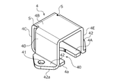
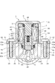
- FIG. 6 is a cross-sectional view taken along the line AA of the solenoid valve in which a solenoid portion is energized. It is a perspective view which developed the yoke. It is a perspective view in the process of manufacturing a yoke. It is a perspective view in the process of manufacturing a yoke. It is a perspective view of a yoke.
- FIG. 7 is a cross-sectional view taken along the line BB of the solenoid valve in which the solenoid portion is not energized. It is a perspective view which shows the deformation example of a yoke.
- the solenoid valve 1 controls the flow rate and pressure of a fluid such as oil or water.
- the solenoid valve 1 is incorporated in a water conditioner and discharges water from a nozzle. The solenoid valve 1 for appropriately changing the water/stoppage will be described.
- the solenoid valve 1 is arranged in a case 2 provided with an inflow path 21 and an outflow path 22 for water, a cylindrical solenoid 30, and an inner side of the solenoid 30. It has a solenoid portion 3 mainly composed of a fixed iron core 31 and a movable iron core 32 and attached to the upper part of the case 2, and a yoke 4 that surrounds the solenoid portion 3 from the outside.
- the case 2 has an inflow path 21, an outflow path 22, a bottomed tubular portion 23 having a housing recess 2A that opens upward and extending in the vertical direction, and a tubular portion 23 extending in the outer diameter direction. It has a pair of projecting portions 24 each having a substantially triangular shape in a top view. Further, a rectangular recess 25 (see FIG. 7) that opens upward is formed between the tubular portion 23 and the overhanging portion 24, and the case 2 is made lighter.
- the inflow passage 21 is formed so as to penetrate the tubular portion 23.
- the bottom portion 2B of the accommodating recess 2A is formed with a protruding portion 6 extending upward, and the protruding portion 6 is formed with a through hole 60 penetrating in the vertical direction and communicating with the outflow passage 22.
- the protrusion 6 has an annular shape in a top view, and a valve seat 61 is formed at the upper end.
- the solenoid portion 3 and the like are partially accommodated and placed in the tubular portion 23.
- the overhanging portion 24 is integrally provided on the tubular portion 23, and the yoke 4 is placed and fixed on the overhanging portion 24.
- the bobbin 8 is mainly formed of resin, and has a through hole 80 penetrating in the vertical direction and an annular opening 81 that is recessed in the inner diameter direction and opens in the outer diameter direction on the side.
- the fixed iron core 31 and the movable iron core 32 are arranged in the through hole 80 of the bobbin 8, and the solenoid 30 is formed and arranged by winding a copper wire around the opening 81.
- the outer circumference on the lower side of the bobbin 8 is an annular shape that is recessed in the inner diameter direction and opened in the outer diameter direction by an upper annular collar 83a extending toward the outer diameter side and a lower annular collar 83b extending toward the outer diameter side.
- a concave portion 83 is formed, and an outer fitting portion 40 (see FIG. 3) of the lower surface plate 4A of the yoke 4 described later is fitted into the concave portion 83.
- the through hole 80 of the bobbin 8 is formed with a step portion 82 that partially protrudes toward the inner diameter side, and the annular convex portion 31a formed on the outer periphery of the fixed iron core 31 contacts the step portion 82 from above.
- the fixed iron core 31 is restricted from moving downward in the vertical direction.
- the movable core 32 is arranged below the fixed core 31 via a compressed spring 32a.
- a valve element 32b is integrally provided at the lower end of the movable iron core 32, and the movable iron core 32 is urged downward by the urging force of the spring 32a, so that the valve element 32b projects.
- the valve seat 61 at the upper end of the portion 6 is abutted.
- the outer periphery of the solenoid 30 and the bobbin 8 is covered with a mold 9.
- the mold 9 is mainly made of resin, and a terminal 91 extending in the outer diameter direction is provided on the upper side.
- the terminal 91 is electrically connected to the solenoid 30, and power is supplied to the terminal 91 to generate a magnetic flux around the solenoid 30.
- the movable iron core 32 is magnetically attracted to the fixed iron core 31 arranged above by the magnetic flux generated when the solenoid 30 is energized, and the valve body 32b arranged below the movable iron core 32 is upward together with the movable iron core. Move to. From this, as shown in FIG. 2, the valve body 32b and the valve seat 61 are separated from each other, that is, the valve body 32b is in an open state, and at this time, the solenoid valve 1 is in a water flow state, in other words, in a valve open state and enters from the inflow path 21. The generated water passes through the through hole 60 of the protrusion 6 and flows into the outflow passage 22.
- the solenoid valve 1 is in a water shut state, in other words, in a closed state.
- the yoke 4 is arranged on the outer side of the mold 9.
- the yoke 4 is formed of a magnetic material, and by surrounding the mold 9 with the yoke 4, a magnetic path for collecting the magnetic flux generated when the solenoid 30 is energized is formed.
- the yoke 4 also functions as a housing for the solenoid section 3.
- the yoke 4 has a substantially cubic shape with an open front surface.
- the yoke 4 has a lower surface plate 4A mounted on the upper end surface 23a (see FIG. 2) of the tubular portion 23 of the case 2, an upper surface plate 4B facing the lower surface plate 4A and parallel to each other, and the lower surface plate 4A and above. It is composed of a connection plate 4C that connects the face plates 4B and is orthogonal to them, and extension pieces 4D and 4E that integrally extend downward from the top plate 4B.
- the lower surface plate 4A includes an outer fitting portion 40 having a shape notched in a substantially U shape from the front end portion to the central portion.
- the outer fitting portion 40 has an arcuate contour having substantially the same size as the peripheral surface 83c formed between the upper annular collar 83a and the lower annular collar 83b of the bobbin 8 (see FIG. 2). It can be fitted into the concave portion 83 of No. 8. Further, as will be described later, the ends of the extension pieces 4D and 4E are bent outward at substantially right angles to form the ears 42, respectively. That is, the extension pieces 4D and 4E are formed of a hanging piece extending downward from the upper surface plate 4B and an ear portion 42 extending outward so as to intersect the hanging piece.
- a through hole 41 as a mounting portion is formed in each ear portion 42 of the extension pieces 4D and 4E.
- the through hole 41 can be screwed into the hole 2a of the overhanging portion 24 of the case 2, which will be described later, by using a headed screw 7 (see FIG. 7).
- a T-shaped plate 4' which is substantially T-shaped in a top view and which is formed by pressing as shown in FIG. 3 is prepared. First, by bending the two central pieces of the T-shaped plate 4'by about 90 degrees, the connecting plate 4C is raised substantially perpendicular to the lower surface plate 4A, and the upper surface plate 4B becomes parallel to the lower surface plate 4A. , The shape shown in FIG.
- the pair of side pieces of the T-shaped plate 4' are bent downward by approximately 90 degrees, so that the extending pieces 4D and 4E are directed downward from the top plate 4B, respectively.
- the shape is as shown in FIG. Since slits S recessed inward are formed at locations where the top plate 4B and the connecting plate 4C are adjacent to each other, the extension pieces 4D and 4E can be easily bent downward.
- the selvage portion 42 is formed by bending the lower portions of the extension pieces 4D and 4E outward, respectively, and the production of the yoke 4 is completed, which is shown in FIG. It becomes a shape.
- the lower surface 4a of the lower surface plate 4A is located slightly below the lower surface 42a of each ear portion 42.
- the solenoid 30 is arranged on the bobbin 8, and then the mold 9 is covered.
- the fixed iron core 31 to which the O-ring 11 is attached is inserted into the through hole 80 of the bobbin 8 from above and fixed in the bobbin 8, and the movable iron core in which the spring 32a and the valve body 32b are assembled from below. 32 is inserted and the solenoid part 3 is unitized.
- the yoke 4 is attached to the unitized solenoid portion 3 by fitting the outer fitting portion 40 of the yoke 4 to the recess 83 of the bobbin 8.
- the vertical position of the bobbin 8 is determined by the lower surface plate 4A of the yoke 4, and the vertical position of the fixed iron core 31 is determined so that the upper end abuts on the lower surface of the upper surface plate 4B of the yoke 4. There is.
- the O-ring 10 is attached to the lower side of the lower annular collar 83b of the bobbin 8 and inserted and placed in the accommodating recess 2A of the case 2.
- the lower surface plate 4A of the yoke 4 is supported in contact with the upper end surface 23a of the tubular portion 23 of the accommodating recess 2A.
- the yoke 4 before assembling the solenoid valve 1 is formed so that the lower surface 4a of the lower surface plate 4A is located slightly below the lower surface 42a of the selvage 42. Therefore, the yoke 4 is formed by the headed screw 7. Since the lower surface plate 4A is slightly bent and deformed upward when the lower plate 4A is fixed to the case 2, the lower surface plate 4A does not float from the case 2, and the assembly accuracy of the solenoid valve 1 is high.
- the lower surface 4a of the lower surface plate 4A and the lower surface 42a of the ear portion 42 may have substantially the same height.
- the yoke 4 is arranged so as to cover the upper surface, both side surfaces, the back surface, and the bottom surface of the solenoid portion 3, so that the solenoid portion 3 serves as a casing of the solenoid portion 3.
- the yoke 4 forms a part of the magnetic path by passing the magnetic flux generated by supplying electric power to the solenoid 30, so that the movable iron core 32 is magnetically attached to the fixed iron core 31 with a small amount of electric power. It can be done.
- the yoke 4 has a lower surface plate 4A mounted on the case 2, an upper surface plate 4B, a connection plate 4C, and an extension piece 4D, and the extension piece 4D has an extension piece 4D.
- An ear portion 42 as an attachment portion attached to the case 2 is formed. From this, since the yoke 4 is supported by the case 2 not only by the connecting plate 4C but also by the extension piece 4D, the upper surface plate 4B can be hardly deformed.
- the extension piece 4D cooperates with the connection plate 4C to form a magnetic path, and the magnetic efficiency is improved.
- the top plate 4B is not easily deformed even if a force is applied to the yoke 4 from the outside of the solenoid valve 1. Further, even if the fluid pressure in the case 2 when the water is stopped is high, an upward force acts on the fixed iron core 31 due to the fluid pressure, and an upward force acts on the yoke 4 from the fixed iron core 31, the top plate 4B Is hard to deform. Furthermore, the top plate 4B is less likely to be deformed by the vibration generated by magnetizing the fixed iron core 31 and the movable iron core 32 with the opening / closing operation of the solenoid valve 1.
- the extension piece 4D is arranged at a position not facing the connection plate 4C, the upper surface plate 4B is less likely to be deformed by external forces from a plurality of directions.
- extension pieces 4D and 4E are provided, and since the pair of extension pieces extend so as to face each other from the upper surface plate 4B of the yoke 4, the extension pieces 4D and 4E Since each of them can be fixed to the case 2, the upper surface plate 4B can be hardly deformed by an external force.
- the lower end of the lower surface plate 4A is arranged between the upper end and the lower end of the extension pieces 4D and 4E, the lower surface plate 4A and the extension pieces 4D and 4E are close to each other, so that the upper surface plate 4B A magnetic circuit is formed by the extension pieces 4D and 4E and the bottom plate 4A, and the magnetic efficiency is improved.
- the extension piece 4D includes an ear portion 42 formed by bending the end portion outward, and a through hole 41 as a mounting portion is formed in the ear portion 42, the yoke 4 is used as a case. It can be fixed from the upper side with respect to 2.
- the yoke 4 is formed by bending a single plate, the number of parts constituting the yoke 4 can be minimized.
- connection plate 4C is raised from the lower surface plate 4A and bent so that the upper surface plate 4B is parallel to the lower surface plate 4A, but the present invention is not limited to this.
- the pieces 4D and 4E may be started up first.
- a form of processing a T-shaped plate 4'in which the upper surface is substantially T-shaped formed by press working is illustrated, but the present invention is not limited to this, and the yoke 4 is molded from a casting or injection molded. It may be done.
- the present invention is not limited to this, and the yoke 4 is fixed to the case 2 by welding. Alternatively, it may be fixed by fitting the concavities and convexities.
- the lower plate 4A of the yoke 4 is arranged at substantially the same height as the selvage portion 42 and the lower ends of the extension pieces 4D and 4E, but the present invention is not limited to this, and the lower plate 4A is more than the lower plate.
- the ears or the lower ends of the extending pieces may be arranged downward.
- the extension piece 4D is bent to form the selvage portion 42, and the headed screw 7 is inserted into the through hole 41 from above and fixed to the case 2, but the present invention is not limited to this.
- a headed screw may be inserted from the side into a through hole extending in the lateral direction of the extending piece extending vertically downward from the top plate and fixed to the case.
- the yoke 4 has a substantially cubic shape with an open front surface, but the present invention is not limited to this, and the upper surface plate has a substantially circular shape and is curved in an arc shape.
- the shape may include a piece and a connecting plate (see FIG. 8).
- Solenoid valve 1 Solenoid valve 2 Case 2a, 2b Hole 3 Solenoid 4 York 4A Bottom plate 4B Top plate 4C Connection plate 4D, 4E Extension piece 6 Protruding part 7 Headed screw 8 Bobbin 9 Mold 21 Inflow path 22 Outflow path 23 Cylindrical Part 24 Overhanging part 30 Solenoid 31 Fixed iron core 32 Movable iron core 40 Outer fitting part 41 Through hole (mounting part) 42 ear
Landscapes
- Physics & Mathematics (AREA)
- Electromagnetism (AREA)
- Engineering & Computer Science (AREA)
- Power Engineering (AREA)
- General Engineering & Computer Science (AREA)
- Mechanical Engineering (AREA)
- Magnetically Actuated Valves (AREA)
- Electromagnets (AREA)
Abstract
上面板が変形し難いヨークを備えた電磁弁を提供する。 流体の流入路(21)と流出路(22)とを有するケース(2)と、ソレノイド(30)と固定鉄心(31)と可動鉄心(32)と弁体(32b)とを有するソレノイド部(3)と、ソレノイド部(3)を囲いケース(2)に取り付けられる磁性材からなるヨーク(4)と、を備えた電磁弁(1)であって、ヨーク(4)は、ケース(2)に載置される下面板(4A)と、上面板(4B)と、下面板(4A)と上面板(4B)とを繋ぐ接続板(4C)と、上面板(4B)から下方に向けて一体的に延出される延出片(4D)と、を有しており、延出片(4D)にはケース(2)に取り付けられる取付部としての貫通孔(41)が形成されている。
Description
本発明は、電磁石の磁力によって弁の開閉を行う電磁弁に関する。
電磁弁は、電磁石を利用した円筒状のソレノイドの内方側に可動鉄心を配置し、ソレノイドに供給する電力により生じる磁力によって可動鉄心に直線的な往復動作をさせることで、弁体の開閉状態を制御する弁であり、制御が容易なことで従来から油圧や水圧の制御に広く用いられている。
このような電磁弁として特許文献1に示される電磁弁は、円筒状のソレノイドと、該ソレノイドの内方側に筒状のチューブ部材に内包された固定鉄心と可動鉄心と、磁性材料からなりソレノイドの外方に配置されるとともに貫通孔をチューブ部材が上下方向に貫通するヨークとを備えており、ソレノイドに電力が供給されることで磁束が生じ、ヨークに磁路を形成させることで可動鉄心が固定鉄心側へスムーズに移動するようになっており、可動鉄心下方に配設されている弁体を開放状態へと移動させるものである。
しかしながら、特許文献1のような電磁弁にあっては、ヨークが前面が開放されたU字状の形状を成しており、下面板がケースに固定されて上面板が片持ち状態であることからヨークの剛性が低いものであった。そのため、ヨークの上面板に力が加わるとヨークが変形し、ヨークの貫通孔を貫通するチューブ部材に内包された固定鉄心及び可動鉄心が傾斜し、電磁弁の精度が低下してしまう虞があった。
本発明は、このような問題点に着目してなされたもので、上面板が変形し難いヨークを備えた電磁弁を提供することを目的とする。
前記課題を解決するために、本発明の電磁弁は、
流体の流入路と流出路とを有するケースと、ソレノイドと固定鉄心と可動鉄心と弁体とを有するソレノイド部と、前記ソレノイド部を囲い前記ケースに取り付けられる磁性材からなるヨークと、を備えた電磁弁であって、
前記ヨークは、前記ケースに載置される下面板と、上面板と、前記下面板と前記上面板とを繋ぐ接続板と、前記上面板から下方に向けて一体的に延出される延出片と、を有しており、
前記延出片には前記ケースに取り付けられる取付部が形成されている。
これによれば、ヨークの上面板から延出された延出片が接続板に加えてケースに支持されるため、上面板を変形し難くできる。加えて、延出片が接続板と協働して磁路を構成することとなり磁気効率が向上する。
流体の流入路と流出路とを有するケースと、ソレノイドと固定鉄心と可動鉄心と弁体とを有するソレノイド部と、前記ソレノイド部を囲い前記ケースに取り付けられる磁性材からなるヨークと、を備えた電磁弁であって、
前記ヨークは、前記ケースに載置される下面板と、上面板と、前記下面板と前記上面板とを繋ぐ接続板と、前記上面板から下方に向けて一体的に延出される延出片と、を有しており、
前記延出片には前記ケースに取り付けられる取付部が形成されている。
これによれば、ヨークの上面板から延出された延出片が接続板に加えてケースに支持されるため、上面板を変形し難くできる。加えて、延出片が接続板と協働して磁路を構成することとなり磁気効率が向上する。
前記延出片は、前記接続板に対して対向しない位置に配置されていてもよい。
これによれば、上面板が複数方向からの外力に対して変形し難くなる。
これによれば、上面板が複数方向からの外力に対して変形し難くなる。
前記延出片は少なくとも一対設けられており、該一対の延出片は互いに対向配置されていてもよい。
これによれば、対向配置された一対の延出片をそれぞれケースに固定できるので、上面板を外力に対して変形し難くできるとともに磁束を良好に通過させることができる。
これによれば、対向配置された一対の延出片をそれぞれケースに固定できるので、上面板を外力に対して変形し難くできるとともに磁束を良好に通過させることができる。
前記下面板の下端は、前記延出片の上端から下端までの間に配置されていてもよい。
これによれば、下面板と延出片とが近接しているので、上面板と延出片と下面板によって磁路が形成され、磁気効率が向上する。
これによれば、下面板と延出片とが近接しているので、上面板と延出片と下面板によって磁路が形成され、磁気効率が向上する。
前記延出片は、端部が外方側に曲折形成された耳部を具備し、前記耳部に前記取付部が形成されていてもよい。
これによれば、ヨークをケースに対して上方側から固定することができる。
これによれば、ヨークをケースに対して上方側から固定することができる。
前記ヨークは、一枚板を曲折することで形成されていてもよい。
これによれば、ヨークを構成する部品点数を少なくできる。
これによれば、ヨークを構成する部品点数を少なくできる。
本発明に係る電磁弁を実施するための形態を実施例に基づいて以下に説明する。
実施例に係る電磁弁につき、図1から図7を参照して説明する。
図1に示されるように、電磁弁1は、油や水などの流体の流量や圧力を制御するものであり、本実施例では、整水器に組み込まれ、ノズルから吐出される水の通水・止水を適宜変更する電磁弁1について説明する。
図1及び図2に示されるように、電磁弁1は、水の流入路21及び流出路22を備えたケース2と、円筒状のソレノイド30と該ソレノイド30の内方側に配設される固定鉄心31及び可動鉄心32とから主に構成されケース2上方に取り付けられるソレノイド部3と、該ソレノイド部3を外方から囲うヨーク4とを有している。
ケース2は、流入路21と、流出路22と、上方側に開口する収容凹部2Aが形成され上下方向に延びる有底の筒状部23と、筒状部23から外径方向に向けて延び上面視略三角形状の一対の張出部24とを有している。さらに、筒状部23と張出部24との間には上方に開放する上面視矩形状の凹部25(図7参照)が形成され、ケース2は軽量化されている。
流入路21は該筒状部23に貫通するように形成されている。また、収容凹部2Aの底部2Bには、上方に向けて延在する突出部6が形成されており、突出部6には上下方向に貫通し流出路22に連通する貫通孔60が形成されている。突出部6は上面視円環形状を成しており、上端には弁座61が形成されている。また、筒状部23には、ソレノイド部3等が一部収容されて載置される。さらに、張出部24は筒状部23に一体的に設けられ、該張出部24にはヨーク4が載置・固定される。
次いでソレノイド部3について説明する。ボビン8は、主に樹脂により成形されており、上下方向に貫通する貫通孔80と、側方には内径方向に凹み外径方向に開口する環状の開口部81と、が形成されている。固定鉄心31及び可動鉄心32はボビン8の貫通孔80に配設され、ソレノイド30は、開口部81に銅線が巻回されて形成・配設されている。さらにボビン8下方側の外周には、外径側に向けて延在する上環状鍔83aと外径側に向けて延在する下環状鍔83bによって内径方向に凹み外径方向に開口する環状の凹部83が形成されており、該凹部83には後述するヨーク4の下面板4Aの外嵌部40(図3参照)が外嵌されるようになっている。
ボビン8の貫通孔80には内径側に向けて一部突出する段部82が形成されており、該段部82に固定鉄心31の外周に形成された環状凸部31aが上方から当接することで固定鉄心31は鉛直方向下方への移動が規制されている。可動鉄心32は圧縮されたスプリング32aを介して固定鉄心31の下方に配置されている。また、可動鉄心32の下端には、弁体32bが一体的に配設されており、前述したスプリング32aの付勢力を受けて可動鉄心32が下方へ付勢されることで弁体32bが突出部6上端の弁座61に当接するようになっている。
ソレノイド30およびボビン8の外周には、モールド9が被覆されている。モールド9は、主に樹脂により成形されており、上方側には外径方向に向けて延出する端子91が設けられている。端子91は、ソレノイド30と電気的に接続されており、端子91に電力が供給されることでソレノイド30の周辺に磁束を発生させるようになっている。
可動鉄心32は、ソレノイド30の通電時に発生した磁束により、上方に配設されている固定鉄心31に磁気的に吸引され、可動鉄心32下方に配設されている弁体32bは可動鉄心と共に上方へ移動する。このことから図2に示されるように、弁体32bと弁座61が離間状態すなわち弁体32bは開放状態となり、このとき電磁弁1は通水状態言い換えると開弁状態となり流入路21から進入した水が突出部6の貫通孔60を通過し流出路22へ流れるようになっている。一方、端子91に電力が供給されていない状態においては、可動鉄心32がスプリング32aによって常時下方に向けて付勢され、弁体32bと弁座61が当接した状態すなわち弁体32bは閉塞状態となって、電磁弁1は止水状態言い換えると閉弁状態となっている。
次にヨーク4について説明する。ヨーク4はモールド9の外方に配設されている。ヨーク4は、磁性材から成形されており、ヨーク4でモールド9を囲うことで、ソレノイド30への通電時に発生された磁束を集める磁路を構成させるようになっている。後述するが、ヨーク4は、ソレノイド部3の筐体としても機能するようになっている。
図6に示されるように、ヨーク4は前面が開放された略立方体形状を成している。ヨーク4は、ケース2の筒状部23の上端面23a(図2参照)に載置される下面板4Aと、下面板4Aに対向し互いに平行をなす上面板4Bと、下面板4Aと上面板4Bを接続しこれらに直交する接続板4Cと、上面板4Bから一体的に下方に延出する延出片4D,4Eと、から構成されている。
下面板4Aは、前端部から中央部にかけて略U字状に切欠かれた形状の外嵌部40を具備している。外嵌部40は、ボビン8の上環状鍔83aと下環状鍔83bとの間に形成されている周面83cと略同寸の円弧状の輪郭を成しており(図2参照)、ボビン8の凹部83に外嵌できるようになっている。また、後述するが、延出片4D,4Eは、端部がそれぞれ外方側へ略直角に曲折されて耳部42がそれぞれ形成されている。すなわち、延出片4D,4Eは、上面板4Bから下方に向けて延びる垂下片と、垂下片に交差するように外方に延びる耳部42とから形成されている。
延出片4D,4Eのそれぞれの耳部42には、取付部としての貫通孔41が形成されている。貫通孔41には、有頭ネジ7を用いて後述するケース2の張出部24の穴部2aとそれぞれ螺合可能となっている(図7参照)。
次にヨーク4の製造について説明する。図3に示される、プレス加工により成形された上面視略T字状のT字板4’を準備する。まずT字板4’の中央片の2箇所を略90度折り曲げることで、接続板4Cは下面板4Aに対して略垂直に立ち上げられ、下面板4Aに対して上面板4Bが平行になり、図4に示される形状となる。
次に、図4に示される状態から、T字板4’の一対の側片を、それぞれ下方に向けて略90度折り曲げることで、上面板4Bから延出片4D,4Eがそれぞれ下方に向けて延在する、図5に示される形状となる。上面板4Bと接続板4Cとが隣り合う箇所には、内方へ凹むスリットSがそれぞれ形成されていることから、延出片4D,4Eを下方へ向けて曲折しやすいようになっている。
最後に、図5に示される状態から、延出片4D,4Eの下部をそれぞれ外方側へ曲折することで、耳部42が形成され、ヨーク4の製造が完了し、図6に示される形状となる。このとき、下面板4Aの下面4aは、それぞれの耳部42の下面42aより僅かに下方へ位置している。
次に電磁弁1の組み立てについて説明する。まず、ボビン8にソレノイド30を配設し、その後モールド9を被覆させる。次に、ボビン8の貫通孔80に、上方からOリング11を装着させた固定鉄心31を挿入し、ボビン8内に固定するとともに、下方からスプリング32aと弁体32bとが組み付けられた可動鉄心32を挿入し、ソレノイド部3がユニット化される。
次いで、ヨーク4の外嵌部40をボビン8の凹部83に外嵌させることで、ヨーク4をユニット化されたソレノイド部3に取り付ける。このとき、ボビン8は上下方向の位置がヨーク4の下面板4Aによって決められているとともに、固定鉄心31は上下方向の位置が上端がヨーク4の上面板4Bの下面に当接して決められている。
その後、ボビン8の下環状鍔83bの下方側にOリング10を取付け、ケース2の収容凹部2A内に挿入・配置する。このときヨーク4の下面板4Aは、収容凹部2Aの筒状部23の上端面23aに当接して支持される。
最後に、ケース2の張出部24の雌ネジが螺設された穴部2a,2bに耳部42の貫通孔41をそれぞれ位置合わせし、有頭ネジ7を穴部2a,2bに上方からそれぞれ螺合させ、電磁弁1の組み立てが完了する。
上述したように、電磁弁1組み立て前のヨーク4は下面板4Aの下面4aが、耳部42の下面42aより僅かに下方に位置するように形成されているので、有頭ネジ7によりヨーク4をケース2に固定する時に、下面板4Aは僅かに上方に向けて撓み変形するので、下面板4Aがケース2から浮くことが無く、電磁弁1の組み立て精度が高くなっている。なお、下面板4Aの下面4aと耳部42の下面42aとを略同一の高さとしてもよい。
また、ヨーク4は、図1、図7に示されているように、ソレノイド部3の上面、両側面、背面、底面を覆うように配置されるので、ソレノイド部3の筐体としてソレノイド部3を外力から保護するとともに、ソレノイド30に電力が供給されることで発生する磁束を通過させ該ヨーク4は磁路の一部を成すことから、少ない電力で可動鉄心32を固定鉄心31に磁着させることができるようになっている。
以上説明したように、ヨーク4は、ケース2に載置される下面板4Aと、上面板4Bと、接続板4Cと、延出片4Dと、を有しており、延出片4Dには、ケース2に取り付けられる取付部としての耳部42が形成されている。このことから、ヨーク4は、接続板4Cに加えて延出片4Dによってもケース2に支持されるため、上面板4Bを変形し難くできる。加えて、延出片4Dが接続板4Cと協働して磁路を構成することとなり磁気効率が向上する。
このように、ヨーク4の剛性が高いので、電磁弁1の外部からヨーク4に力が加わっても上面板4Bは変形し難い。また、止水時のケース2内の流体圧力が高く、流体圧力による力が固定鉄心31に上向きの力が作用し、固定鉄心31からヨーク4が上向きの力が作用しても、上面板4Bは変形し難い。さらにまた、電磁弁1の開閉動作に伴って固定鉄心31と可動鉄心32とが磁着されることで生じる振動に対しても、上面板4Bが変形し難いようになっている。
また、延出片4Dは、接続板4Cに対して対向しない位置に配置されていることから、上面板4Bは複数方向からの外力に対して変形し難くなっている。
また、延出片4D,4Eは、少なくとも一対設けられており、該一対の延出片は互いにヨーク4の上面板4Bから対向するように延出されていることから、延出片4D,4Eをそれぞれケース2に固定できるので、上面板4Bを外力に対して変形し難くできる。
また、下面板4Aの下端は、延出片4D,4Eの上端から下端までの間に配置されていることから、下面板4Aと延出片4D,4Eが近接しているので、上面板4Bと延出片4D,4Eと下面板4Aによって磁気回路が形成され、磁気効率が向上する。
また、延出片4Dは、端部が外方側に曲折され形成された耳部42を具備し、耳部42に取付部としての貫通孔41が形成されていることから、ヨーク4をケース2に対して上方側から固定することができる。
また、ヨーク4は、一枚板を曲折することで形成されていることから、ヨーク4を構成する部品点数を最小限に抑えることができる。
以上、本発明の実施例を図面により説明してきたが、具体的な構成はこれら実施例に限られるものではなく、本発明の要旨を逸脱しない範囲における変更や追加があっても本発明に含まれる。
例えば、ヨーク4の製造手順については、下面板4Aから接続板4Cを立ち上げ、下面板4Aに対して上面板4Bが平行になるように曲折させると説明したが、これに限られず、延出片4D,4Eを先に立ち上げてもよい。
また、前記実施例では、プレス加工により成形された上面視略T字状のT字板4’を加工する形態を例示したが、これに限られず、ヨーク4を鋳物から成形したり、射出成型することとしてもよい。
また、前記実施例では、ヨーク4をケース2に対して有頭ネジ7を用いて螺合させ固定させる形態を例示したが、これに限られず、ヨーク4をケース2に対して溶接による固定、または凹凸嵌合による固定としてもよい。
また、実施例ではヨーク4の下面板4Aは、耳部42や延出片4D,4Eの下端と略同じ高さ位置に配置される形態を例示したが、これに限られず、下面板よりも耳部や延出片の下端が下方に配置されるものであってもよい。
また、前記実施例では、上面板4Bから延出片が2片延出される形態を例示したが、これに限られず、1片または3片以上としてもよい。
また、前記実施例では、延出片4Dを曲折し耳部42が形成され、貫通孔41に上方から有頭ネジ7を挿通しケース2に固定する形態を例示したが、これに限られず、上面板から下方に向けて鉛直に延びる延出片の側方向に延びる貫通孔に、側方側から有頭ネジを挿通しケースに固定することとしてもよい。
また、前記実施例では、ヨーク4は前面が開放された略立方体形状を成している形態を例示したが、これに限られず、上面板を略円形状とし、円弧状に湾曲された延出片及び接続板を備える形状としてもよい(図8参照)。
1 電磁弁
2 ケース
2a,2b 穴部
3 ソレノイド部
4 ヨーク
4A 下面板
4B 上面板
4C 接続板
4D,4E 延出片
6 突出部
7 有頭ネジ
8 ボビン
9 モールド
21 流入路
22 流出路
23 筒状部
24 張出部
30 ソレノイド
31 固定鉄心
32 可動鉄心
40 外嵌部
41 貫通孔(取付部)
42 耳部
2 ケース
2a,2b 穴部
3 ソレノイド部
4 ヨーク
4A 下面板
4B 上面板
4C 接続板
4D,4E 延出片
6 突出部
7 有頭ネジ
8 ボビン
9 モールド
21 流入路
22 流出路
23 筒状部
24 張出部
30 ソレノイド
31 固定鉄心
32 可動鉄心
40 外嵌部
41 貫通孔(取付部)
42 耳部
Claims (6)
- 流体の流入路と流出路とを有するケースと、ソレノイドと固定鉄心と可動鉄心と弁体とを有するソレノイド部と、前記ソレノイド部を囲い前記ケースに取り付けられる磁性材からなるヨークと、を備えた電磁弁であって、
前記ヨークは、前記ケースに載置される下面板と、上面板と、前記下面板と前記上面板とを繋ぐ接続板と、前記上面板から下方に向けて一体的に延出される延出片と、を有しており、前記延出片には前記ケースに取り付けられる取付部が形成されている電磁弁。 - 前記延出片は、前記接続板に対して対向しない位置に配置されている請求項1に記載の電磁弁。
- 前記延出片は少なくとも一対設けられており、該一対の延出片は互いに対向配置されている請求項1または2に記載の電磁弁。
- 前記下面板の下端は、前記延出片の上端から下端までの間に配置されている請求項1ないし3のいずれかに記載の電磁弁。
- 前記延出片は、端部が外方側に曲折形成された耳部を具備し、前記耳部に前記取付部が形成されている請求項1ないし4のいずれかに記載の電磁弁。
- 前記ヨークは、一枚板を曲折することで形成されている請求項1ないし5のいずれかに記載の電磁弁。
Priority Applications (2)
| Application Number | Priority Date | Filing Date | Title |
|---|---|---|---|
| CN202080016398.1A CN113490810A (zh) | 2019-03-05 | 2020-03-03 | 电磁阀 |
| JP2021504114A JP7387244B2 (ja) | 2019-03-05 | 2020-03-03 | 電磁弁 |
Applications Claiming Priority (2)
| Application Number | Priority Date | Filing Date | Title |
|---|---|---|---|
| JP2019039841 | 2019-03-05 | ||
| JP2019-039841 | 2019-03-05 |
Publications (1)
| Publication Number | Publication Date |
|---|---|
| WO2020179791A1 true WO2020179791A1 (ja) | 2020-09-10 |
Family
ID=72338332
Family Applications (1)
| Application Number | Title | Priority Date | Filing Date |
|---|---|---|---|
| PCT/JP2020/008945 Ceased WO2020179791A1 (ja) | 2019-03-05 | 2020-03-03 | 電磁弁 |
Country Status (3)
| Country | Link |
|---|---|
| JP (1) | JP7387244B2 (ja) |
| CN (1) | CN113490810A (ja) |
| WO (1) | WO2020179791A1 (ja) |
Citations (4)
| Publication number | Priority date | Publication date | Assignee | Title |
|---|---|---|---|---|
| US3255327A (en) * | 1963-05-09 | 1966-06-07 | Teledyne Prec Inc | Lightweight high-speed relay |
| US4322701A (en) * | 1980-04-24 | 1982-03-30 | Hi-G Incorporated | Magnetic circuit for miniature relays |
| JPH0323267U (ja) * | 1989-07-17 | 1991-03-11 | ||
| JP2014138180A (ja) * | 2013-01-18 | 2014-07-28 | Saginomiya Seisakusho Inc | モールドコイルおよびモールドコイルを用いた電磁弁、ならびに、モールドコイルの製造方法 |
Family Cites Families (5)
| Publication number | Priority date | Publication date | Assignee | Title |
|---|---|---|---|---|
| JPH08285114A (ja) * | 1995-04-11 | 1996-11-01 | Unisia Jecs Corp | ソレノイドバルブのヨーク構造 |
| JP3849158B2 (ja) * | 1995-08-22 | 2006-11-22 | 松下電工株式会社 | リレー |
| JP3626129B2 (ja) * | 2001-10-26 | 2005-03-02 | 有限会社ミサキ工業 | ソレノイドヨーク |
| JP4453677B2 (ja) * | 2006-04-25 | 2010-04-21 | パナソニック電工株式会社 | 電磁開閉装置 |
| CN207441385U (zh) * | 2017-08-30 | 2018-06-01 | 浙江三花智能控制股份有限公司 | 一种电磁线圈 |
-
2020
- 2020-03-03 WO PCT/JP2020/008945 patent/WO2020179791A1/ja not_active Ceased
- 2020-03-03 CN CN202080016398.1A patent/CN113490810A/zh active Pending
- 2020-03-03 JP JP2021504114A patent/JP7387244B2/ja active Active
Patent Citations (4)
| Publication number | Priority date | Publication date | Assignee | Title |
|---|---|---|---|---|
| US3255327A (en) * | 1963-05-09 | 1966-06-07 | Teledyne Prec Inc | Lightweight high-speed relay |
| US4322701A (en) * | 1980-04-24 | 1982-03-30 | Hi-G Incorporated | Magnetic circuit for miniature relays |
| JPH0323267U (ja) * | 1989-07-17 | 1991-03-11 | ||
| JP2014138180A (ja) * | 2013-01-18 | 2014-07-28 | Saginomiya Seisakusho Inc | モールドコイルおよびモールドコイルを用いた電磁弁、ならびに、モールドコイルの製造方法 |
Also Published As
| Publication number | Publication date |
|---|---|
| JP7387244B2 (ja) | 2023-11-28 |
| JPWO2020179791A1 (ja) | 2020-09-10 |
| CN113490810A (zh) | 2021-10-08 |
Similar Documents
| Publication | Publication Date | Title |
|---|---|---|
| CN113586744B (zh) | 电磁阀 | |
| CN110410554A (zh) | 电磁阀及其制造方法 | |
| JP4207209B2 (ja) | 電磁弁 | |
| JP3822667B2 (ja) | 圧力切換弁 | |
| JP2017207159A (ja) | 電磁弁 | |
| JP6372995B2 (ja) | 電磁弁 | |
| JP2005172224A (ja) | 電磁弁 | |
| JP5949265B2 (ja) | 電磁弁およびその製造方法 | |
| JP7387244B2 (ja) | 電磁弁 | |
| JP3671524B2 (ja) | 電磁弁 | |
| JP6613086B2 (ja) | 電磁弁 | |
| CN115380180B (zh) | 用于车辆电磁阀的边缘镦厚的翻转衔铁 | |
| JP3825311B2 (ja) | 電磁弁 | |
| JP6576674B2 (ja) | 電磁弁 | |
| JP2018179120A (ja) | 電磁弁 | |
| JP3833525B2 (ja) | 電磁弁 | |
| KR20190131234A (ko) | 솔레노이드 밸브 | |
| KR100677853B1 (ko) | 브레이크 컨트롤 시스템용 솔레노이드밸브 | |
| JP7355433B2 (ja) | 電磁弁 | |
| JP2005277233A (ja) | ソレノイド及びその製造方法 | |
| JP7753156B2 (ja) | 電磁弁 | |
| US20240376995A1 (en) | Miniature media isolated rocking diaphragm valve with enhanced flux circuit | |
| JP2020165446A (ja) | アクチュエータ及びそれを備えたバルブ | |
| CN212517054U (zh) | 电磁体装置、触点装置以及电磁继电器装置 | |
| CN211901754U (zh) | 一种燃油计量阀 |
Legal Events
| Date | Code | Title | Description |
|---|---|---|---|
| 121 | Ep: the epo has been informed by wipo that ep was designated in this application |
Ref document number: 20765859 Country of ref document: EP Kind code of ref document: A1 |
|
| ENP | Entry into the national phase |
Ref document number: 2021504114 Country of ref document: JP Kind code of ref document: A |
|
| NENP | Non-entry into the national phase |
Ref country code: DE |
|
| 122 | Ep: pct application non-entry in european phase |
Ref document number: 20765859 Country of ref document: EP Kind code of ref document: A1 |