WO2020179528A1 - 情報処理システム、情報処理方法、管理装置、及びプログラム - Google Patents
情報処理システム、情報処理方法、管理装置、及びプログラム Download PDFInfo
- Publication number
- WO2020179528A1 WO2020179528A1 PCT/JP2020/007291 JP2020007291W WO2020179528A1 WO 2020179528 A1 WO2020179528 A1 WO 2020179528A1 JP 2020007291 W JP2020007291 W JP 2020007291W WO 2020179528 A1 WO2020179528 A1 WO 2020179528A1
- Authority
- WO
- WIPO (PCT)
- Prior art keywords
- terminal device
- management device
- information processing
- distance
- processing system
- Prior art date
- Legal status (The legal status is an assumption and is not a legal conclusion. Google has not performed a legal analysis and makes no representation as to the accuracy of the status listed.)
- Ceased
Links
Images









Classifications
-
- G—PHYSICS
- G08—SIGNALLING
- G08B—SIGNALLING SYSTEMS, e.g. PERSONAL CALLING SYSTEMS; ORDER TELEGRAPHS; ALARM SYSTEMS
- G08B7/00—Signalling systems according to two or more of groups G08B3/00 - G08B6/00
- G08B7/06—Signalling systems according to two or more of groups G08B3/00 - G08B6/00 using electric transmission, e.g. involving audible and visible signalling through the use of sound and light sources
-
- G—PHYSICS
- G01—MEASURING; TESTING
- G01S—RADIO DIRECTION-FINDING; RADIO NAVIGATION; DETERMINING DISTANCE OR VELOCITY BY USE OF RADIO WAVES; LOCATING OR PRESENCE-DETECTING BY USE OF THE REFLECTION OR RERADIATION OF RADIO WAVES; ANALOGOUS ARRANGEMENTS USING OTHER WAVES
- G01S5/00—Position-fixing by co-ordinating two or more direction or position line determinations; Position-fixing by co-ordinating two or more distance determinations
- G01S5/02—Position-fixing by co-ordinating two or more direction or position line determinations; Position-fixing by co-ordinating two or more distance determinations using radio waves
- G01S5/14—Determining absolute distances from a plurality of spaced points of known location
-
- G—PHYSICS
- G01—MEASURING; TESTING
- G01S—RADIO DIRECTION-FINDING; RADIO NAVIGATION; DETERMINING DISTANCE OR VELOCITY BY USE OF RADIO WAVES; LOCATING OR PRESENCE-DETECTING BY USE OF THE REFLECTION OR RERADIATION OF RADIO WAVES; ANALOGOUS ARRANGEMENTS USING OTHER WAVES
- G01S1/00—Beacons or beacon systems transmitting signals having a characteristic or characteristics capable of being detected by non-directional receivers and defining directions, positions, or position lines fixed relatively to the beacon transmitters; Receivers co-operating therewith
- G01S1/02—Beacons or beacon systems transmitting signals having a characteristic or characteristics capable of being detected by non-directional receivers and defining directions, positions, or position lines fixed relatively to the beacon transmitters; Receivers co-operating therewith using radio waves
- G01S1/68—Marker, boundary, call-sign, or like beacons transmitting signals not carrying directional information
-
- G—PHYSICS
- G01—MEASURING; TESTING
- G01S—RADIO DIRECTION-FINDING; RADIO NAVIGATION; DETERMINING DISTANCE OR VELOCITY BY USE OF RADIO WAVES; LOCATING OR PRESENCE-DETECTING BY USE OF THE REFLECTION OR RERADIATION OF RADIO WAVES; ANALOGOUS ARRANGEMENTS USING OTHER WAVES
- G01S11/00—Systems for determining distance or velocity not using reflection or reradiation
- G01S11/02—Systems for determining distance or velocity not using reflection or reradiation using radio waves
- G01S11/06—Systems for determining distance or velocity not using reflection or reradiation using radio waves using intensity measurements
-
- G—PHYSICS
- G01—MEASURING; TESTING
- G01S—RADIO DIRECTION-FINDING; RADIO NAVIGATION; DETERMINING DISTANCE OR VELOCITY BY USE OF RADIO WAVES; LOCATING OR PRESENCE-DETECTING BY USE OF THE REFLECTION OR RERADIATION OF RADIO WAVES; ANALOGOUS ARRANGEMENTS USING OTHER WAVES
- G01S5/00—Position-fixing by co-ordinating two or more direction or position line determinations; Position-fixing by co-ordinating two or more distance determinations
- G01S5/02—Position-fixing by co-ordinating two or more direction or position line determinations; Position-fixing by co-ordinating two or more distance determinations using radio waves
- G01S5/0269—Inferred or constrained positioning, e.g. employing knowledge of the physical or electromagnetic environment, state of motion or other contextual information to infer or constrain a position
- G01S5/02695—Constraining the position to lie on a curve or surface
-
- G—PHYSICS
- G08—SIGNALLING
- G08G—TRAFFIC CONTROL SYSTEMS
- G08G1/00—Traffic control systems for road vehicles
- G08G1/16—Anti-collision systems
-
- H—ELECTRICITY
- H04—ELECTRIC COMMUNICATION TECHNIQUE
- H04Q—SELECTING
- H04Q9/00—Arrangements in telecontrol or telemetry systems for selectively calling a substation from a main station, in which substation desired apparatus is selected for applying a control signal thereto or for obtaining measured values therefrom
-
- G—PHYSICS
- G08—SIGNALLING
- G08B—SIGNALLING SYSTEMS, e.g. PERSONAL CALLING SYSTEMS; ORDER TELEGRAPHS; ALARM SYSTEMS
- G08B21/00—Alarms responsive to a single specified undesired or abnormal condition and not otherwise provided for
- G08B21/18—Status alarms
- G08B21/22—Status alarms responsive to presence or absence of persons
Definitions
- the present invention relates to an information processing system, an information processing method, a management device, and a program.
- Non-Patent Document 1 a system that detects a vehicle traveling at high speed in the construction lane and issues a warning with sound and light to a traffic guide or a worker.
- Milight develops "Vehicle jump warning system" Doremi (registered trademark) "-Contribution to reduce personal injury caused by vehicle jumping into construction restricted area-", [online], October 19, 2016, [Heisei February 19, 31st search], Internet (URL: https://www.mirait.co.jp/news/upload_files/20161019.pdf)
- Non-Patent Document 1 Since the above technology of Non-Patent Document 1 can be applied only to one leading vehicle, it cannot be applied to a following vehicle. Therefore, there is a need for a system that pre-determines the approach of a car that is likely to collide and warns the construction workers.
- An object of the present invention made in view of the above point is to provide an information processing system, an information processing method, a management device, and a program capable of estimating the path of a movable terminal device.
- An information processing system including a plurality of transmitting devices capable of transmitting a predetermined radio wave, a terminal device capable of receiving the predetermined radio wave, and a management device communicably connected to the terminal device.
- the terminal device measures the intensity of radio waves received from each of the plurality of transmitting devices at predetermined time intervals, and transmits the measurement result to the management device,
- the management device calculates the distance between the terminal device and each of the plurality of transmitting devices at predetermined time from the measurement result, and determines the position of the terminal device at predetermined time from the calculated distance. calculate.
- the information processing method executed in an information processing system including a plurality of transmitting devices capable of transmitting a predetermined radio wave, a terminal device capable of receiving the predetermined radio wave, and a management device communicably connected to the terminal device. And A step in which the terminal device measures the intensity of radio waves received from each of the plurality of transmitting devices at predetermined time intervals and transmits the measurement result to the management device; The management device calculates the distance between the terminal device and each of the plurality of transmitting devices at predetermined time from the measurement result, and determines the position of the terminal device at predetermined time from the calculated distance. A step of calculating, including.
- a management device communicatively connected to a terminal device, Upon receiving the measurement result of the radio wave intensity at predetermined time intervals from the terminal device, From the measurement result, the distance between the terminal device and each of the plurality of transmission devices at predetermined time intervals is calculated, and the position of the terminal device at predetermined time intervals is calculated from the calculated distance.
- the program according to the present invention is The computer is caused to function as the management device.
- the information processing method it is possible to estimate the course of the movable terminal device.
- FIG. 13A It is a schematic diagram when a confirmation experiment is carried out. It is a figure which shows the radio field strength and the distance obtained in the confirmation experiment. It is a figure which shows the coordinates defined in the confirmation experiment. It is a figure which shows the arrangement of the article used in a confirmation experiment. It is a figure which shows the distance for every predetermined time between the terminal device and each transmission device obtained by the confirmation experiment. It is a figure which shows the circle drawn in the coordinates about a certain time. It is a figure which shows the circle drawn in the coordinates about another time. It is a figure which shows the distance which the terminal device moved in coordinates. It is a figure which shows the distance and the speed calculated in the situation of FIG. 13A. It is a figure which shows the flowchart of the process which a management apparatus executes.
- the terminal device 2 of the present embodiment is, for example, a smartphone possessed by a driver of a moving body 2a such as a vehicle.
- the terminal device 2 may be installed in the moving body 2a.
- the terminal device 2 is movable.
- the terminal device 2 has a Bluetooth (registered trademark) receiving function.
- the transmission device 1 (first transmission device 1a and second transmission device 1b) of the present embodiment is a beacon installed on the side of the road near the construction work zone K and capable of transmitting Bluetooth (registered trademark) radio waves. ..
- As the beacon for example, those described in the following documents can be applied.
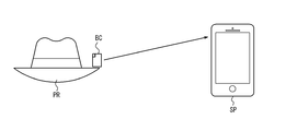
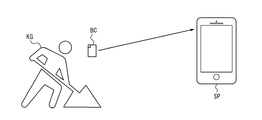
- FIG. 2A and 2B are diagrams illustrating an example of using the beacon BC.
- the beacon BC may be installed in the vicinity of the product PR in the store.
- the beacon BC can transmit detailed information of the product or the like to the smartphone SP of the customer who has approached within a predetermined distance.
- the smartphone SP can display detailed information of the product and the like via the application.
- the beacon BC may be applied to the construction site KG.
- the beacon BC is installed at the construction site KG, and sends a notification to the smartphone SP of the driver of the moving body that has approached the construction site KG.
- the smartphone SP that has received the notification outputs a voice such as "It is a construction site. Please be careful.” through the application.
- the terminal device 2 receives Bluetooth (registered trademark) radio waves from each of the first transmitting device 1a and the second transmitting device 1b at predetermined time intervals, and measures the radio wave intensity.
- the terminal device 2 transmits the measurement result to the management device 3 (not shown).
- the management device 3 calculates and estimates the distance from each transmission device 1 to the terminal device 2 from the relationship between the radio field intensity and the distance.
- the management device 3 calculates the coordinates of the terminal device 2 from the distance between the transmission devices 1 and the distance between each transmission device 1 and the terminal device 2.
- the management device 3 calculates the speed of the terminal device 2 from the variation of the calculated coordinates over time.
- the management device 3 calculates the coordinates of the terminal device 2 from at least two transmitting devices 1.
- the management device 3 can determine the traveling lane of the moving body 2a from the calculated coordinates and can determine whether to output the warning information by voice or screen display. Further, the management device 3 can acquire the position information and the speed information of the moving body 2a. From the acquired information, the management device 3 can determine the possibility that the moving body 2a will collide with the construction work zone K, for example, and output warning information indicating that the collision possibility is high by voice or screen display. ..
- the construction work zone K is an obstacle on the traveling route of the moving body 2a. In this way, the management device 3 can prompt the driver or a worker on the spot to call attention.
- the present invention is applicable not only to determine the possibility of collision of a vehicle but also to grasp the speed and position of various other moving objects.
- FIG. 3A is a diagram showing a main configuration of the information processing system S of this embodiment.
- the information processing system S includes a first transmission device 1a, a second transmission device 1b, a terminal device 2, and a management device 3.
- the terminal device 2 is possessed by a pedestrian, a driver of the moving body 2a, or the like.
- the terminal device 2 can receive radio waves such as Bluetooth (registered trademark) from the first transmission device 1a and the second transmission device 1b.
- the terminal device 2 and the management device 3 are communicably connected to each other via an arbitrary network such as the Internet.
- the information processing system S may include three or more transmitters 1.
- two terminal devices 2 are shown.
- the number of terminal devices 2 included in the information processing system S may be one or three or more.
- one management device 3 is shown.
- the information processing system S may include two or more management devices 3.
- the functional block diagram of the terminal device 2 and the management device 3 will be described in detail below. Each function of the terminal device 2 and the management device 3 will be described in detail, but it is not intended to exclude other functions.
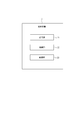
- the terminal device 2 includes a storage unit 21, a control unit 22, and a communication unit 23.
- the terminal device 2 is a Bluetooth (registered trademark) receiving terminal (for example, a smartphone) carried by the driver of the moving body 2a.
- the application is installed in the terminal device 2. Using this application, the terminal device 2 measures the received Bluetooth (registered trademark) radio field intensity and transmits the measurement result to the management device 3.
- the terminal device 2 may be carried by a pedestrian or a vehicle such as an automobile or a motorcycle.
- the storage unit 21 includes one or more memories.
- the “memory” is, for example, a semiconductor memory, a magnetic memory, an optical memory, or the like, but is not limited to these.
- Each memory included in the storage unit 21 may function as, for example, a main storage device, an auxiliary storage device, or a cache memory.
- the storage unit 21 may store information on a result analyzed or processed by the control unit 22.
- the storage unit 21 may store various kinds of information regarding the operation or control of the terminal device 2.
- the control unit 22 includes one or more processors.
- the “processor” may be a general-purpose processor or a dedicated processor specialized for specific processing.
- the control unit 22 controls the overall operation of the terminal device 2.
- the control unit 22 controls other functional units included in the terminal device 2.
- the communication unit 23 is an interface, and includes a communication module that communicates with at least one of the first transmission device 1a, the second transmission device 1b, and the management device 3.
- the communication unit 23 can receive a radio wave from the first transmission device 1a or the second transmission device 1b and can transmit the measurement result of the radio field intensity to the management device 3.
- the management device 3 includes an information determination unit 31, a reception unit 32, a conversion calculation unit 33, a distance / time information storage unit 34, a coordinate conversion unit 35, a recording unit 36, a coordinate top distance calculation unit 37, and coordinates. It includes an upper distance / time information storage unit 38, a derivation unit 39, a speed calculation unit 40, a speed information storage unit 41, and a collision possibility determination unit 42.
- the processing executed by the information judgment unit 31, the conversion calculation unit 33, the coordinate conversion unit 35, the coordinate distance calculation unit 37, the derivation unit 39, the speed calculation unit 40, and the collision possibility judgment unit 42 is performed by one or more processors. Will be executed.
- the distance/time information storage unit 34, the recording unit 36, the coordinate distance/time information storage unit 38, and the speed information storage unit 41 may be one or more memories.
- the information determination unit 31 receives the radio wave intensity information and the time information from the terminal device 2, it determines whether the receiver is the terminal device 2 used in the coordinate definition described later or the terminal device 2 installed on the moving body 2a. To do.
- the receiving unit 32 is an interface that receives information from the information judging unit 31.
- the conversion calculator 33 converts the radio field intensity into a distance using a predetermined formula.
- the distance/time information storage unit 34 stores the calculation result of the conversion calculation unit 33.
- the coordinate conversion unit 35 converts the positional relationship between the terminal device 2 and each transmission device 1 into coordinates in step A2 described later.
- the recording unit 36 records the coordinates defined for the terminal device 2 and each transmitting device 1.
- the coordinate distance calculation unit 37 calculates the distance between the terminal device 2 and each transmission device 1 on the coordinate.
- the coordinated distance / time information storage unit 38 stores the calculated distance in association with the time information received from the terminal device 2.
- the deriving unit 39 derives the intersection coordinates from the intersections of a plurality of circles drawn as described later for each time and outputs the coordinates to the coordinate distance/time information storage unit 38.
- the speed calculator 40 calculates the moving speed of the terminal device 2 from the derived plurality of intersection coordinates.
- the speed information storage unit 41 accumulates the calculated movement speed.
- the collision possibility determination unit 42 determines the collision possibility from the speed information acquired from the speed information storage unit 41 and the position information acquired from the coordinate distance/time information storage unit 38.
- the information processing system S executes the coordinate definition of the position of the transmission device 1.
- the outline of the coordinate definition is shown in FIG.
- the terminal device 2 notifies the user of the terminal device 2 by voice, screen display, or the like to place the terminal device 2 on a straight line passing through the first transmission device 1a and the second transmission device 1b. ..
- the terminal device 2 receives the Bluetooth (registered trademark) radio wave transmitted from each transmitting device 1 and measures the radio wave intensity.
- the terminal device 2 transmits the measurement result to the management device 3.
- the management device 3 calculates the distance between the terminal device 2 and each transmission device 1 from the measurement result received from the terminal device 2.
- the management device 3 sets the coordinates of the position of the terminal device 2 as (0, 0), sets the straight line passing through each transmission device 1 as the x-axis, and sets the straight line passing through the coordinates of the terminal device 2 and perpendicular to the x-axis as y. Set as an axis.
- the management device 3 determines the coordinates of each transmission device 1 in proportion to the actual distance.
- the management device 3 sets the coordinates of the first transmission device 1a as ( ⁇ , 0) and the coordinates of the second transmission device 1b as ( ⁇ , 0).
- the management device 3 may set the positive / negative of each axis in any direction.
- the terminal device 2 When the setting is completed, the terminal device 2 notifies the user of the terminal device 2 that it is not necessary to leave the terminal device 2 on the spot.
- the information processing system S has a distance between the transmission devices 1 even if the position of each transmission device 1 is changed according to the situation at the site. It is possible to omit the trouble of measuring and inputting on the spot. Further, the information processing system S can execute the coordinate definition corresponding to the absolute distance required for detecting the approach of the moving body 2a to the construction work zone K or the like.
- step A2 a device such as an alarm is installed at an arbitrary position in the construction work zone K before step A2, and the positional relationship between the alarm and each transmission device 1 is managed by the management device 3. You may memorize it. With such a configuration, when the management device 3 defines the coordinates in step A2, the coordinates of the alarm device or the like may be set on the defined coordinates.
- step A2 when the distance between each transmission device 1 and the terminal device 2 is known or the distance is measurable, the management device 3 does not execute the coordinate definition of step A2. Good. Instead, the terminal device 2 receives the input of the coordinates (that is, ⁇ and ⁇ ) of each transmitting device 1 according to the distance. The terminal device 2 transmits the input coordinate information to the management device 3. The management device 3 may set the coordinates of the terminal device 2 from the received coordinate information.
- Step A3 When the mobile body 2a approaches each transmission device 1, the management device 3 detects that the terminal device 2 installed on the mobile body 2a has received a radio wave intensity equal to or higher than a certain value.
- the management device 3 may start the following position specifying processing.
- FIG. 5A shows an outline of the position identification process.
- the management device 3 sets the start time of the position identification process as t0. At this time, the management device 3 has information on the intensity of radio waves from each of the first transmitting device 1a and the second transmitting device 1b. The management device 3 converts the radio field intensity into a distance using a predetermined conversion formula.
- the distance from the first transmission device 1a to the terminal device 2 is A0
- the distance from the second transmission device 1b to the terminal device 2 is B0.
- the management device 3 has a circle having a radius A0 (or a size corresponding to the scale of the coordinates) centered on the first transmitting device 1a and a second transmitting device 1b as the center on the coordinates defined in step A2.
- a circle having the radius B0 (or the size corresponding to the scale of the coordinates) is drawn. Points on the same circumference are points where the same radio field strength is measured.
- the intersection of the two drawn circles is a candidate for the existing position of the terminal device 2, and is set as (x0, y0) on the coordinates shown in FIG. 5B. There are two points of intersection of the circles, one with a positive value of y0 and the other with a negative value of y0, but the management device 3 may select either one.
- the management device 3 When a positive value is selected, the management device 3 also selects a positive value in step A4 below. On the other hand, when a negative value is selected, the management device 3 also selects a negative value in step A4 below.
- Step A4 The management device 3 executes the above step A3 again after a lapse of a certain time from the time t0 (in particular, a time during which the mobile body 2a does not go out of the area where the mobile body 2a can communicate with each transmission device 1). Draw a circle again as shown in 5C. As illustrated in FIG. 5D, the management device 3 acquires the coordinates (x1, y1) of the terminal device 2 at time t1.
- the management device 3 can determine the high or low possibility of collision as follows by using the calculated speed information and the position information of the moving body 2a.
- the position of the construction work zone K may be set manually, or may be set at the same position as the position of an alarm device or the like installed in the construction work zone K.
- the management device 3 makes a comparison, and if the calculated speed is smaller than the threshold value, it is determined that the moving body 2a stops before the construction work zone K or changes the traveling direction to the right, and therefore the possibility of collision is low. You can judge that.
- the management device 3 may determine that the moving body 2a does not seem to avoid the construction work zone K, and thus may determine that the possibility of collision is high. At this time, the management device 3 sends warning information indicating that there is a high possibility of collision to an alarm device (speaker, monitor, etc.) installed near the construction work zone K, or a mobile terminal carried by a worker in the construction work zone K. , Or to the terminal device 2.
- the terminal that has received the warning information can output the warning information by voice, screen display, or the like to reduce personal injury.
- the management device 3 can execute the above processing for the subsequent moving body 2a.
- the speed information and the position information are stored for each moving body 2a. Therefore, the present invention is also applicable to the following vehicle.
- the management device 3 converts the radio field intensity into the distance using the above relational expression.
- the management device 3 may use the expression if a relational expression between the radio field intensity and the distance exists separately (for example, empirically).
- Step B1 In this experiment, the information processing system S shown in FIG. 3A was used. Two transmitters 1 were used.
- FIG. 7 shows the installation status of each transmitter 1.
- the first transmitting device 1a, the terminal device 2, and the second transmitting device 1b are installed so as to exist on the same straight line L and the straight line L is parallel to the lane R.
- the distance between each transmitting device 1 and the terminal device 2 is 5 m.
- the radio field strength and distance were measured four times in total.
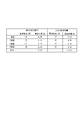
- FIG. 8 shows the radio field intensity obtained as a result of the measurement and the distance calculated from the radio field intensity.
- the average value of the distance is 5.01 m. That is, the management device 3 was able to obtain a value that is almost the same as the actual distance in the experiment.
- the coordinates defined from the values obtained as a result of the measurement are shown in FIG. One scale of the coordinates here corresponds to the actual distance of 1 m.
- Step B3 Following step B2, further experiments were performed with the arrangement shown in FIG. 10A.
- the terminal device 2 first moved to the left side of the drawing along a trajectory T parallel to a straight line passing through each transmitting device 1, assuming a lane.
- the terminal device 2 changes its course at the position closest to the second transmission device 1b, and moves along the track T diagonally forward and rightward in the traveling direction.
- the position closest to the second transmitting device 1b is set to a position 3 m away from the second transmitting device 1b in the direction perpendicular to the straight line L.
- the terminal device 2 receives a radio wave of -71 dB or more from the second transmission device 1b, and the information processing system S starts the processing flow.
- the speed of the terminal device 2 at this time is about 40 km / h.
- the radio field intensity and calculated distance obtained in this experiment are shown in FIG. 10B. There is a slight discrepancy between the actual distance and the calculated distance. However, when the information processing system S is applied to a roadway, the deviation is relatively small, so there is no problem.
- the coordinates of the intersection of the two circles are (4.55, 3.23).
- FIG. 13A shows the two intersections obtained in step B3 and step B4.
- the calculation result is shown in FIG. 13B.
- the distance between the two points is 11.3 m, which substantially matches the actual distance of 10.44 m.
- the speed calculated by the scale correction is 40.6 km/h, which is almost the same as the actual speed of 40 km/h. It is considered that the cause of the error between the calculated speed and the actual speed is that it was difficult to move the terminal device 2 while keeping the actual speed at 40 km / h.
- FIG. 14 shows a flowchart of the process executed by the management device 3.
- step S1 the information determination unit 31 of the management device 3 determines from which terminal the radio field intensity information and the time information have been received.
- the receiving unit 32 receives the information from the information determining unit 31 in step S2.
- step S3 the conversion calculation unit 33 converts the radio field strength into a distance.
- step S4 the distance/time information storage unit 34 stores the distance and time information calculated in step S3.
- step S5 the coordinate conversion unit 35 converts the positional relationship between the terminal device 2 and each transmission device 1 into coordinates.
- step S6 the recording unit 36 defines the coordinates of the terminal device 2 and each transmitting device 1.
- the coordinates of the terminal device 2, the first transmission device 1a, and the second transmission device 1b are set to (0, 0), ( ⁇ , 0), and ( ⁇ , 0), respectively.
- the recording unit 36 records the set contents and transfers them to the coordinate distance calculating unit 37.
- the management device 3 executes the following steps S14 to S20.
- the reception unit 32 receives the information from the information determination unit 31 in step S11.
- step S12 the conversion calculation unit 33 performs calculation to convert the radio field intensity into a distance.
- step S13 the distance/time information storage unit 34 stores the distance and time information calculated in step S12.
- step S14 the coordinate distance calculating unit 37 calculates the distance between the terminal device 2 and each transmitting device 1 on the coordinates when the coordinates are set by an arbitrary method.
- step S15 the coordinate distance/time information storage unit 38 records the distance calculated in step S14 and the time corresponding to the distance.
- step S16 the deriving unit 39 draws a circle on the coordinates using the distance recorded in step S15, and derives the intersection coordinates of the circles.
- the derivation unit 39 derives the intersection coordinates for each time.
- step S17 the coordinate distance / time information storage unit 38 records the intersection coordinates for each time derived in step S16.
- step S18 the speed calculation unit 40 calculates the speed of the terminal device 2 from the plurality of intersection coordinates recorded at each time in step S17. Since the calculation method is as described above, the description here will be omitted.
- step S19 the speed information storage unit 41 stores the speed calculated in step S18.
- step S20 the collision possibility determination unit 42 determines the collision possibility from the speed information accumulated in step S18 and the position information accumulated in step S15. Since the determination method is as described above, the description here will be omitted.
- the terminal device 2 measures the intensity of the radio wave received from each of the plurality of transmitting devices 1 at predetermined time intervals, and transmits the measurement result to the management device 3.
- the management device 3 calculates the distance between the terminal device 2 and each of the plurality of transmitting devices 1 at predetermined time intervals from the measurement result, and calculates the position of the terminal device 2 at predetermined time intervals from the calculated distance. ..
- the management device 3 can estimate the course of the terminal device 2 by grasping the position and speed of the terminal device 2. Further, the management device 3 can reduce the number of accidents by executing such estimation for the subsequent terminal device 2.
- the terminal device 2 is installed on the moving body 2a, and the management device 3 can collide with the obstacle on the traveling path from the calculated position and the calculated speed. Judge the sex. With this configuration, the management device 3 can reduce accidents.
- the management device 3 stores the position of the obstacle, sets the threshold value of the speed according to the positional relationship between the terminal device 2 and the obstacle, and compares the speed of the terminal device 2 with the threshold value. A comparison is made to determine the possibility that the moving body 2a collides with an obstacle. With this configuration, the management device 3 can more accurately estimate the course while reducing erroneous determinations.
- the management device 3 when the management device 3 determines that there is a high possibility of collision, it transmits warning information indicating that there is a high possibility of collision to the terminal device 2.
- the terminal device 2 outputs warning information.
- the management device 3 can reduce accidents.
- the transmission device 1 is installed only on one side of the roadway (that is, on the left side in the traveling direction of the moving body 2a).
- the transmitting device 1 may be installed on both sides of the roadway (ie, opposite lanes).
- the management device 3 can acquire the distance data in opposite phases from the transmission devices 1 on both sides, so that it is possible to more accurately estimate the course of the terminal device 2 and determine the possibility of collision.
- the management device 3 determines the possibility of collision from the position and speed of the moving body 2a.
- the management device 3 in the other embodiment may further determine the traveling direction of the moving body 2a and determine the possibility of collision from the traveling direction. Specifically, even if the management device 3 determines that there is a high possibility of collision based on the position and speed of the moving body 2a in the above-described embodiment, the traveling direction of the moving body 2a in another embodiment is the construction work. If the direction is to avoid the band K, it may be judged that the possibility of collision is low.
- the management device 3 of this embodiment can also be realized by an arbitrary computer and program. Specifically, a program that describes the processing content for realizing each function of the management device 3 is recorded in a recording medium such as a memory, and the processor reads and executes the program. Such programs can also be provided over the network.
- this program may be recorded on a computer-readable medium. It can be installed on a computer using a computer-readable medium.
- the computer-readable medium in which the program is recorded may be a non-transitory recording medium.
- the non-transient recording medium is not particularly limited, but may be, for example, a recording medium such as a CD-ROM or a DVD-ROM.
- S Information processing system 1 (1a, 1b) Transmission device 2 Terminal device 21 Storage unit 22 Control unit 23 Communication unit 2a Mobile device 3 Management device 31 Information judgment unit 32 Reception unit 33 Conversion calculation unit 34 Distance / time information storage unit 35 Coordinates Conversion unit 36 Recording unit 37 Coordinate distance calculation unit 38 Coordinate distance / time information storage unit 39 Derivation unit 40 Speed calculation unit 41 Speed information storage unit 42 Collision possibility judgment unit
Landscapes
- Physics & Mathematics (AREA)
- General Physics & Mathematics (AREA)
- Engineering & Computer Science (AREA)
- Radar, Positioning & Navigation (AREA)
- Remote Sensing (AREA)
- Computer Networks & Wireless Communication (AREA)
- Electromagnetism (AREA)
- Traffic Control Systems (AREA)
- Position Fixing By Use Of Radio Waves (AREA)
Abstract
移動可能な端末装置の進路を推定する。情報処理システム(S)は、所定の電波を送信可能な複数の送信装置(1a、1b)と、所定の電波を受信可能な端末装置(2)と、端末装置に通信可能に接続される管理装置(3)とを含み、端末装置(2)は、複数の送信装置(1a、1b)の各々から受信した電波の強度を所定時間毎に測定し、測定結果を管理装置(3)に送信し、管理装置(3)は、測定結果から、端末装置(2)と複数の送信装置(1a、1b)の各々との間の所定時間毎の距離を算出し、算出された距離から端末装置(2)の所定時間毎の位置を算出する。
Description
本発明は、情報処理システム、情報処理方法、管理装置、及びプログラムに関する。
道路舗装あるいは道路下に埋設されているインフラの点検・補修時等には、道路上に工事作業帯を設置し作業を行う必要がある。その際には、車両が適切に通行できるようにするために、交通誘導員又は標識等を配置し、交通整理をする必要がある。一方で、このような取り組みにもかかわらず、工事作業帯に車両が誤って衝突し、人身事故となるケースが後を絶たない。このような事故は運転者の不注意又は居眠りによるものが大半である。そのような人身事故を低減するために、工事車線を高速で走行する車両を検知し交通誘導員又は作業員に音と光で警告を発するシステムが知られている(例えば非特許文献1)。
ミライト、"車両飛び込まれ警告システム「ドレミ(登録商標)」を開発~工事規制エリアへの車両飛び込まれによる人身故被害低減寄与~"、[online]、平成28年10月19日、[平成31年2月19日検索]、インターネット(URL: https://www.mirait.co.jp/news/upload_files/20161019.pdf)
上記の非特許文献1の技術は1台の先頭車両のみにしか適用することができないので、後続車両に適用することができない。そこで、衝突しそうな車の接近をあらかじめ判別し、工事の従事者に警告するシステムが必要とされている。
かかる点に鑑みてなされた本発明の目的は、移動可能な端末装置の進路を推定することができる情報処理システム、情報処理方法、管理装置、及びプログラムを提供することにある。
上記課題を解決するため、本発明に係る情報処理システムは、
所定の電波を送信可能な複数の送信装置と、前記所定の電波を受信可能な端末装置と、前記端末装置に通信可能に接続される管理装置とを含む情報処理システムであって、
前記端末装置は、前記複数の送信装置の各々から受信した電波の強度を所定時間毎に測定し、測定結果を前記管理装置に送信し、
前記管理装置は、前記測定結果から、前記端末装置と前記複数の送信装置の各々との間の所定時間毎の距離を算出し、前記算出された距離から前記端末装置の所定時間毎の位置を算出する。
所定の電波を送信可能な複数の送信装置と、前記所定の電波を受信可能な端末装置と、前記端末装置に通信可能に接続される管理装置とを含む情報処理システムであって、
前記端末装置は、前記複数の送信装置の各々から受信した電波の強度を所定時間毎に測定し、測定結果を前記管理装置に送信し、
前記管理装置は、前記測定結果から、前記端末装置と前記複数の送信装置の各々との間の所定時間毎の距離を算出し、前記算出された距離から前記端末装置の所定時間毎の位置を算出する。
上記課題を解決するため、本発明に係る情報処理方法は、
所定の電波を送信可能な複数の送信装置と、前記所定の電波を受信可能な端末装置と、前記端末装置に通信可能に接続される管理装置とを含む情報処理システムにおいて実行される情報処理方法であって、
前記端末装置が、前記複数の送信装置の各々から受信した電波の強度を所定時間毎に測定し、測定結果を前記管理装置に送信するステップと、
前記管理装置が、前記測定結果から、前記端末装置と前記複数の送信装置の各々との間の所定時間毎の距離を算出し、前記算出された距離から前記端末装置の所定時間毎の位置を算出するステップと、
を含む。
所定の電波を送信可能な複数の送信装置と、前記所定の電波を受信可能な端末装置と、前記端末装置に通信可能に接続される管理装置とを含む情報処理システムにおいて実行される情報処理方法であって、
前記端末装置が、前記複数の送信装置の各々から受信した電波の強度を所定時間毎に測定し、測定結果を前記管理装置に送信するステップと、
前記管理装置が、前記測定結果から、前記端末装置と前記複数の送信装置の各々との間の所定時間毎の距離を算出し、前記算出された距離から前記端末装置の所定時間毎の位置を算出するステップと、
を含む。
上記課題を解決するため、本発明に係る管理装置は、
端末装置に通信可能に接続される管理装置であって、
前記端末装置から所定時間毎の電波強度の測定結果を受信し、
前記測定結果から、前記端末装置と複数の送信装置の各々との間の所定時間毎の距離を算出し、前記算出された距離から前記端末装置の所定時間毎の位置を算出する。
端末装置に通信可能に接続される管理装置であって、
前記端末装置から所定時間毎の電波強度の測定結果を受信し、
前記測定結果から、前記端末装置と複数の送信装置の各々との間の所定時間毎の距離を算出し、前記算出された距離から前記端末装置の所定時間毎の位置を算出する。
上記課題を解決するため、本発明に係るプログラムは、
コンピュータを、上記管理装置として機能させる。
コンピュータを、上記管理装置として機能させる。
本発明に係る情報処理システム、情報処理方法、管理装置、及びプログラムによれば、移動可能な端末装置の進路を推定することができる。
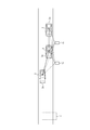
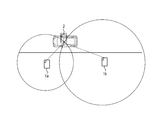
まず本実施形態において実行される処理の概要が説明される。図1に示すように、本実施形態の端末装置2は一例として、例えば車両等の移動体2aの運転者によって所持されるスマートフォンである。端末装置2は移動体2aに設置されてよい。端末装置2は移動可能である。端末装置2はBluetooth(登録商標)の受信機能を有する。本実施形態の送信装置1(第1の送信装置1a及び第2の送信装置1b)は工事作業帯Kの近傍の車道脇に設置され、Bluetooth(登録商標)の電波を送信可能なビーコンである。ビーコンには例えば次の文献に記載されるものが適用可能である。
WHERE、“EXBeaconプラットフォーム”、[online]、[平成31年2月19日検索]、インターネット(URL: https://where123.jp/platform)
WHERE、“EXBeaconプラットフォーム”、[online]、[平成31年2月19日検索]、インターネット(URL: https://where123.jp/platform)
図2A及び図2Bは、ビーコンBCの使用例を説明する図である。図2Aに示すように、ビーコンBCは店舗内の商品PRの近傍に設置されてよい。このときビーコンBCは、所定距離内に接近した顧客のスマートフォンSPに、商品の詳細情報等を送信することができる。スマートフォンSPはアプリケーションを介して、商品の詳細情報等を表示することができる。他方で図2Bに示すように、ビーコンBCは工事現場KGに適用されてよい。具体的にはビーコンBCは工事現場KGに設置され、工事現場KGに接近した移動体の運転者のスマートフォンSPに通知を送信する。通知を受信したスマートフォンSPは例えば、アプリケーションを介して、「工事現場です。注意して下さい。」等の音声を出力する。
図1の説明に戻ると、端末装置2は所定時間毎に、第1の送信装置1a及び第2の送信装置1bの各々からBluetooth(登録商標)の電波を受信し、電波強度を測定する。端末装置2は測定結果を管理装置3(不図示)に送信する。管理装置3は、電波強度と距離との関係から、各送信装置1から端末装置2までの距離を算出して推定する。管理装置3は、送信装置1間の距離と、各送信装置1と端末装置2との間の距離とから端末装置2の座標を算出する。管理装置3は算出された座標の時間毎の変異から、端末装置2の速度を算出する。
このように管理装置3は端末装置2の座標を少なくとも2台の送信装置1から算出する。管理装置3は、算出された座標から、移動体2aの走行車線を判定し、警告情報を音声又は画面表示等により出力するか否かを決定することができる。更に管理装置3は、移動体2aの位置情報と速度情報とを取得することができる。管理装置3は取得された情報から、移動体2aが例えば工事作業帯Kへ衝突する可能性を判定し、衝突可能性が高いことを示す警告情報を音声又は画面表示等により出力することができる。工事作業帯Kは、移動体2aの走行経路上の障害物である。このように管理装置3は運転者又は現場の作業員等に注意喚起を促すことができる。本願発明は車両の衝突可能性の判断のみならず、他の様々な移動体の速度及び位置を把握したいときに適用可能である。
以下、本実施形態において実行される情報処理方法が詳細に説明される。
[ステップA1]
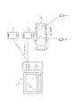
図3Aは、本実施形態の情報処理システムSにおける主な構成を示す図である。情報処理システムSは、第1の送信装置1aと第2の送信装置1bと端末装置2と管理装置3とを含む。端末装置2は歩行者又は移動体2aの運転者等によって所持される。端末装置2は、第1の送信装置1a及び第2の送信装置1bから例えばBluetooth(登録商標)等の電波を受信可能である。端末装置2と管理装置3とは例えばインターネット等の任意のネットワークを介して互いに通信可能に接続される。
図3Aは、本実施形態の情報処理システムSにおける主な構成を示す図である。情報処理システムSは、第1の送信装置1aと第2の送信装置1bと端末装置2と管理装置3とを含む。端末装置2は歩行者又は移動体2aの運転者等によって所持される。端末装置2は、第1の送信装置1a及び第2の送信装置1bから例えばBluetooth(登録商標)等の電波を受信可能である。端末装置2と管理装置3とは例えばインターネット等の任意のネットワークを介して互いに通信可能に接続される。
図3Aでは説明の簡便のため、2つの送信装置1a及び1bが記載される。しかし、情報処理システムSは3つ以上の送信装置1を含んでよい。図3Aでは、2つの端末装置2が記載される。しかし、情報処理システムSに含まれる端末装置2の数は1つ又は3つ以上であってよい。図3Aでは1つの管理装置3が記載される。しかし、情報処理システムSは2つ以上の管理装置3を含んでよい。
下記で端末装置2と管理装置3との機能ブロック図が詳細に説明される。端末装置2と管理装置3との各機能を詳細に説明するが、他の機能を排除することを意図したものではない。
図3Bに示すように端末装置2は記憶部21と制御部22と通信部23とを含む。端末装置2は、移動体2aの運転者が所持するBluetooth(登録商標)受信端末(例えばスマートフォン)である。端末装置2にはアプリケーションがインストールされる。端末装置2はこのアプリケーションを用いて、受信したBluetooth(登録商標)の電波強度を測定し、測定結果を管理装置3に送信する。端末装置2は歩行者によって所持されてよいし、自動車又はバイク等の車両によって所持されてよい。
記憶部21は1つ以上のメモリを含む。「メモリ」は、例えば半導体メモリ、磁気メモリ、又は光メモリ等であるが、これらに限られない。記憶部21に含まれる各メモリは、例えば主記憶装置、補助記憶装置、又はキャッシュメモリとして機能してもよい。記憶部21は、制御部22によって分析又は処理された結果の情報を記憶してよい。記憶部21は、端末装置2の動作又は制御に関する各種情報等を記憶してよい。
制御部22は1つ以上のプロセッサを備える。「プロセッサ」は、汎用のプロセッサ、又は特定の処理に特化した専用のプロセッサであってよい。例えば、制御部22は、端末装置2の全体の動作を制御する。制御部22は、端末装置2に含まれる他の機能部の制御を行う。
通信部23はインタフェースであり、第1の送信装置1a、第2の送信装置1b及び管理装置3の少なくとも1つとの通信を行う通信モジュールを含む。通信部23は第1の送信装置1a又は第2の送信装置1bから電波を受信すると共に、電波強度の測定結果を管理装置3に送信することができる。
図3Cに示すように、管理装置3は情報判断部31と受信部32と変換計算部33と距離・時刻情報蓄積部34と座標変換部35と記録部36と座標上距離計算部37と座標上距離・時刻情報蓄積部38と導出部39と速度算出部40と速度情報蓄積部41と衝突可能性判断部42とを含む。情報判断部31と変換計算部33と座標変換部35と座標上距離計算部37と導出部39と速度算出部40と衝突可能性判断部42とが実行する処理は、1又は複数のプロセッサによって実行される。距離・時刻情報蓄積部34と記録部36と座標上距離・時刻情報蓄積部38と速度情報蓄積部41とは、1つ以上のメモリであってよい。
情報判断部31は、端末装置2から電波強度情報及び時刻情報を受信すると、受信元が、後述の座標定義で使用される端末装置2か、移動体2aに設置された端末装置2かを判定する。
受信部32は情報判断部31からの情報を受信するインタフェースである。
変換計算部33は、所定の式を用いて、電波強度を距離に変換する。
距離・時刻情報蓄積部34は、変換計算部33による計算結果を蓄積する。
座標変換部35は、後述のステップA2にて、端末装置2と各送信装置1との位置関係を座標に変換する。
記録部36は、端末装置2と各送信装置1とにつき定義された座標を記録する。
座標上距離計算部37は、座標上で、端末装置2と各送信装置1との間の距離を計算する。
座標上距離・時刻情報蓄積部38は、計算された距離と、端末装置2から受信した時刻情報とを対応付けて蓄積する。
導出部39は、時刻毎に、後述のように描かれる複数の円の交点から交点座標を導出し、座標上距離・時刻情報蓄積部38に出力する。
速度算出部40は、導出された複数の交点座標から、端末装置2の移動速度を算出する。
速度情報蓄積部41は、算出された移動速度を蓄積する。
衝突可能性判断部42は、速度情報蓄積部41から取得した速度情報と、座標上距離・時刻情報蓄積部38から取得した位置情報とから、衝突可能性を判断する。
[ステップA2]
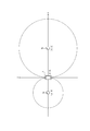
情報処理システムSはまず、送信装置1の位置の座標定義を実行する。座標定義の概要を図4に示す。具体的には端末装置2は、端末装置2のユーザに対し、第1の送信装置1a及び第2の送信装置1bを通る直線上に端末装置2を置くように音声又は画面表示等により通知する。端末装置2は、各送信装置1から発信されるBluetooth(登録商標)の電波を受信し、電波強度を測定する。端末装置2は測定結果を管理装置3に送信する。電波強度と距離には正の相関がある。そこで管理装置3は、端末装置2から受信した測定結果から、端末装置2と各送信装置1との間の距離を計算する。管理装置3は端末装置2の位置の座標を(0、0)と設定し、各送信装置1を通る直線をx軸として設定し、端末装置2の座標を通りx軸に垂直な直線をy軸として設定する。管理装置3は、各送信装置1の座標を、実距離と比例させて決定する。ここでは管理装置3は、第1の送信装置1aの座標を(α、0)、第2の送信装置1bの座標を(β、0)と設定する。なお管理装置3は、各軸の正負を任意の方向に設定してよい。設定が完了すると、端末装置2は、端末装置2をその場に置いておく必要がないことを端末装置2のユーザに通知する。このように電波を利用してステップA2を実行することによって、情報処理システムSは、現場の状況に応じて各送信装置1の位置が変更された場合であっても、送信装置1間の距離を現場が測定及び入力する手間を省略することができる。更に情報処理システムSは、工事作業帯K等への移動体2aの接近を検知するために必要となる、絶対的な距離に対応した座標定義を実行することができる。
情報処理システムSはまず、送信装置1の位置の座標定義を実行する。座標定義の概要を図4に示す。具体的には端末装置2は、端末装置2のユーザに対し、第1の送信装置1a及び第2の送信装置1bを通る直線上に端末装置2を置くように音声又は画面表示等により通知する。端末装置2は、各送信装置1から発信されるBluetooth(登録商標)の電波を受信し、電波強度を測定する。端末装置2は測定結果を管理装置3に送信する。電波強度と距離には正の相関がある。そこで管理装置3は、端末装置2から受信した測定結果から、端末装置2と各送信装置1との間の距離を計算する。管理装置3は端末装置2の位置の座標を(0、0)と設定し、各送信装置1を通る直線をx軸として設定し、端末装置2の座標を通りx軸に垂直な直線をy軸として設定する。管理装置3は、各送信装置1の座標を、実距離と比例させて決定する。ここでは管理装置3は、第1の送信装置1aの座標を(α、0)、第2の送信装置1bの座標を(β、0)と設定する。なお管理装置3は、各軸の正負を任意の方向に設定してよい。設定が完了すると、端末装置2は、端末装置2をその場に置いておく必要がないことを端末装置2のユーザに通知する。このように電波を利用してステップA2を実行することによって、情報処理システムSは、現場の状況に応じて各送信装置1の位置が変更された場合であっても、送信装置1間の距離を現場が測定及び入力する手間を省略することができる。更に情報処理システムSは、工事作業帯K等への移動体2aの接近を検知するために必要となる、絶対的な距離に対応した座標定義を実行することができる。
ステップA2における追加例として、ステップA2以前に工事作業帯K内の任意の位置に警報機等の装置を設置しておき、警報機等と各送信装置1との間の位置関係を管理装置3に記憶させてよい。このような構成により、ステップA2において管理装置3が座標定義を行ったとき、定義された座標上に警報機等の座標を設定してよい。
ステップA2の代替例として、各送信装置1と端末装置2との間の距離が既知であるとき又はその距離が測定可能であるとき、管理装置3は上記ステップA2の座標定義を実行しなくてよい。代わりに端末装置2は、距離に応じて、各送信装置1の座標(すなわち、α及びβ)の入力を受け付ける。端末装置2は入力された座標情報を管理装置3に送信する。管理装置3は、受信した座標情報から、端末装置2の座標を設定してよい。
[ステップA3]
移動体2aが各送信装置1に接近すると、管理装置3は、移動体2aに設置された端末装置2が一定値以上の電波強度を受信したことを検出する。管理装置3は下記の位置特定処理を開始してよい。
移動体2aが各送信装置1に接近すると、管理装置3は、移動体2aに設置された端末装置2が一定値以上の電波強度を受信したことを検出する。管理装置3は下記の位置特定処理を開始してよい。
図5Aに位置特定処理の概要を示す。管理装置3は位置特定処理の開始時刻をt0と設定する。このとき管理装置3は、第1の送信装置1a及び第2の送信装置1bの各々からの電波の強度情報を有する。管理装置3は、所定の変換式を用いて電波強度を距離に変換する。ここでは一例として第1の送信装置1aから端末装置2までの距離をA0とし、第2の送信装置1bから端末装置2までの距離をB0とする。
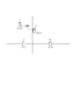
管理装置3は、ステップA2で定義した座標上に、第1の送信装置1aを中心とした半径A0(又は座標の縮尺に対応した大きさ)の円と、第2の送信装置1bを中心とした半径B0(又は座標の縮尺に対応した大きさ)の円とを描く。同一円周上の点は、同一の電波強度が測定される点である。描かれた2つの円の交点が端末装置2の存在位置の候補であり、図5Bに示す座標上で(x0、y0)と設定される。円の交点はy0の値が正であるものと負であるものとで2点存在するが、管理装置3はどちらを選択してもよい。本実施形態では一例としてy0の値が正である場合を説明する。正の値が選択されたとき、管理装置3は下記のステップA4でも正の値を選択する。一方で負の値が選択されたとき、管理装置3は下記のステップA4でも負の値を選択する。
[ステップA4]
管理装置3は、時刻t0から一定時間(ここでは特に、移動体2aが各送信装置1と通信可能なエリアの外に出ない程度の時間)の経過後、上記ステップA3を再度実行し、図5Cに示すように再度円を描く。図5Dに示すように、管理装置3は時刻t1に端末装置2の座標(x1、y1)を取得する。
管理装置3は、時刻t0から一定時間(ここでは特に、移動体2aが各送信装置1と通信可能なエリアの外に出ない程度の時間)の経過後、上記ステップA3を再度実行し、図5Cに示すように再度円を描く。図5Dに示すように、管理装置3は時刻t1に端末装置2の座標(x1、y1)を取得する。
[ステップA5]
管理装置3は、ステップA3及びステップA4で取得した座標情報から、距離と速度とを計算する。具体的には管理装置3は、次の数式を用いて、図6に示す2点間の距離dを計算する。

管理装置3は計算された距離dに所定の縮尺補正を行って、実際の距離である実距離d’を算出する。更に管理装置3は、次の数式を用いて移動体2aの速度sを算出する。
s=d’/(t1-t0)
このようにして管理装置3は、移動体2aの実速度を割り出すことができる。
管理装置3は、ステップA3及びステップA4で取得した座標情報から、距離と速度とを計算する。具体的には管理装置3は、次の数式を用いて、図6に示す2点間の距離dを計算する。
s=d’/(t1-t0)
このようにして管理装置3は、移動体2aの実速度を割り出すことができる。
図1のように片側対面通行の場合、移動体2aの速度が大きくても移動体2aが工事作業帯Kから十分遠ければ、衝突可能性が高いと判断するのは性急である。一方で移動体2aが工事作業帯Kに近くても移動体2aの速度が小さければ(例えば、工事作業帯Kの手前で減速していれば)衝突可能性は低いと判断することが可能である。そこで管理装置3は、算出した速度情報と移動体2aの位置情報とを用いて、次のように衝突可能性の高低を判断することができる。すなわち管理装置3は、時刻t=1のときの移動体2aの位置と工事作業帯Kの位置との間の距離に応じて速度の閾値を設定して記憶する。距離が短いほど、速度の閾値は小さく設定されてよい。工事作業帯Kの位置は、手入力によって設定されてよいし、工事作業帯K内に設置された警報機等の位置と同一の位置に設定されてよい。管理装置3は比較を行い、算出された速度が閾値よりも小さければ、移動体2aは工事作業帯Kの手前で停止し又は進行方向を右方に変更すると判断し、もって衝突可能性は低いと判断してよい。一方で管理装置3は、算出された速度が閾値以上であれば、移動体2aは工事作業帯Kを避ける様子がないと判断し、もって衝突可能性は高いと判断してよい。このとき管理装置3は、衝突可能性が高いことを示す警告情報を、工事作業帯Kの近傍に設置された警報機(スピーカ、モニタ等)、工事作業帯Kの作業員が所持する携帯端末、又は、端末装置2に送信する。警告情報を受信した端末は、音声又は画面表示等により警告情報を出力して、人身事故を低減することができる。
管理装置3は、以上の処理を、後続の移動体2aに対して実行することができる。この場合、速度情報と位置情報とは、移動体2a毎に記憶される。このため、本願発明は後続車両に対しても適用可能である。
[確認実験]
上記の情報処理システムSにつき実験(シミュレーション)を行った。実験で用いた、電波強度と距離の関係式は次の通りである。

この式では、距離をd[m]、送信装置が発する電波強度をT[dB]、端末装置2が受信した電波強度をR[dB]と設定される。この式は、自由空間で受信信号の強度が距離の2乗に反比例することを示したフリスの伝搬公式に、本実験環境に適したパラメータを適用したものである。この式におけるnは端末装置2の機種又は障害物の有無によって変化し得る係数である。今回の実験環境では、n=2.79と設定し、T=-57と設定した。
上記の情報処理システムSにつき実験(シミュレーション)を行った。実験で用いた、電波強度と距離の関係式は次の通りである。
以下の説明では、管理装置3は上記の関係式を用いて電波強度を距離に変換する。代替例として、電波強度と距離との関係式が別に(例えば経験的に)存在するならば、管理装置3はその式を用いてよい。
[ステップB1]
この実験では上記の図3Aに示す情報処理システムSが用いられた。送信装置1は2台用いられた。
この実験では上記の図3Aに示す情報処理システムSが用いられた。送信装置1は2台用いられた。
[ステップB2]
図7に各送信装置1の設置状況を示す。この図に示すように、第1の送信装置1aと端末装置2と第2の送信装置1bとは同一の直線L上に存在し且つ直線Lが車線Rと平行になるように設置される。各送信装置1と端末装置2との間の距離は5mである。電波強度と距離との測定は計4回行われた。測定の結果得られた電波強度と、電波強度から算出された距離とを図8に示す。この図に示すように、距離の平均値は5.01mである。すなわち管理装置3は、実験で、実距離とほぼ相違ない値を得ることができた。測定の結果得られた値から定義された座標を図9に示す。ここでの座標の1目盛は実距離の1mに対応する。
図7に各送信装置1の設置状況を示す。この図に示すように、第1の送信装置1aと端末装置2と第2の送信装置1bとは同一の直線L上に存在し且つ直線Lが車線Rと平行になるように設置される。各送信装置1と端末装置2との間の距離は5mである。電波強度と距離との測定は計4回行われた。測定の結果得られた電波強度と、電波強度から算出された距離とを図8に示す。この図に示すように、距離の平均値は5.01mである。すなわち管理装置3は、実験で、実距離とほぼ相違ない値を得ることができた。測定の結果得られた値から定義された座標を図9に示す。ここでの座標の1目盛は実距離の1mに対応する。
[ステップB3]
ステップB2に続いて、図10Aに示すような配置で更に実験を行った。この実験において端末装置2はまず、車線を想定して、各送信装置1を通る直線と平行な軌道Tを図の左方に向かって移動した。端末装置2は、第2の送信装置1bに最も近づく位置にて進路を変更し、軌道Tに沿って進行方向右斜め前方に移動した。本確認実験では検証を簡単にするために、第2の送信装置1bに最も近づく位置は、第2の送信装置1bから直線Lと垂直方向に3m離れた位置に設定される。このとき端末装置2は第2の送信装置1bから-71dB以上の電波を受信し、情報処理システムSは処理フローを開始する。このときの時刻をt=0とする。このときの端末装置2の速度は約40km/hである。図10Aに示すように、端末装置2は、t=0の時刻から1秒後であるt=1の時刻のときに、第1の送信装置1aから直線Lと垂直方向に6m離れた位置を通る。
ステップB2に続いて、図10Aに示すような配置で更に実験を行った。この実験において端末装置2はまず、車線を想定して、各送信装置1を通る直線と平行な軌道Tを図の左方に向かって移動した。端末装置2は、第2の送信装置1bに最も近づく位置にて進路を変更し、軌道Tに沿って進行方向右斜め前方に移動した。本確認実験では検証を簡単にするために、第2の送信装置1bに最も近づく位置は、第2の送信装置1bから直線Lと垂直方向に3m離れた位置に設定される。このとき端末装置2は第2の送信装置1bから-71dB以上の電波を受信し、情報処理システムSは処理フローを開始する。このときの時刻をt=0とする。このときの端末装置2の速度は約40km/hである。図10Aに示すように、端末装置2は、t=0の時刻から1秒後であるt=1の時刻のときに、第1の送信装置1aから直線Lと垂直方向に6m離れた位置を通る。
この実験において得られた電波強度と算出距離とを図10Bに示す。実距離と算出距離との間にはわずかなずれが存在する。しかし、情報処理システムSが車道に適用される場合にはそのずれは比較的小さいので問題とならない。
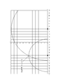
管理装置3は、図11に示すように、t=0のときの算出距離をもとに座標に円を描く。2つの円の交点の座標は(4.55、3.23)である。
[ステップB4]
管理装置3は、図12に示すように、t=1のときの算出距離をもとに座標に円を描く。2つの円の交点の座標は(-5.12、6.15)である。
管理装置3は、図12に示すように、t=1のときの算出距離をもとに座標に円を描く。2つの円の交点の座標は(-5.12、6.15)である。
[ステップB5]
図13Aに、ステップB3及びステップB4にて求められた2つの交点を示す。管理装置3は、時刻t=0のときの座標と時刻t=1のときの座標との間の距離と、その距離を移動するときの端末装置2の速度とを算出する。算出結果を図13Bに示す。この図に示すように2点間の距離は11.3mであり、実距離である10.44mとほぼ一致する。縮尺補正を行って算出された速度は40.6km/hであり、実速度40km/hとほぼ一致する。算出された速度と実速度との誤差の原因は、実速度を40km/hに保ったまま端末装置2を移動させるのは困難であったためと考えられる。
図13Aに、ステップB3及びステップB4にて求められた2つの交点を示す。管理装置3は、時刻t=0のときの座標と時刻t=1のときの座標との間の距離と、その距離を移動するときの端末装置2の速度とを算出する。算出結果を図13Bに示す。この図に示すように2点間の距離は11.3mであり、実距離である10.44mとほぼ一致する。縮尺補正を行って算出された速度は40.6km/hであり、実速度40km/hとほぼ一致する。算出された速度と実速度との誤差の原因は、実速度を40km/hに保ったまま端末装置2を移動させるのは困難であったためと考えられる。
図14に、管理装置3が実行する処理のフローチャートを示す。
ステップS1にて管理装置3の情報判断部31は、どの端末から電波強度情報及び時刻情報を受信したかを判定する。
管理装置3が、ステップA2で座標定義に使用される端末装置2から情報を受信したと判定すると、ステップS2にて受信部32は情報判断部31からその情報を受信する。
ステップS3にて変換計算部33は電波強度を距離に変換する。
ステップS4にて距離・時刻情報蓄積部34は、ステップS3にて計算された距離と時刻情報とを蓄積する。
ステップS5にて座標変換部35は端末装置2と各送信装置1との位置関係を座標に変換する。
ステップS6にて記録部36は、端末装置2と各送信装置1との座標を定義する。例えば端末装置2、第1の送信装置1a、及び第2の送信装置1bの座標はそれぞれ、(0、0)、(α、0)及び(β、0)と設定される。記録部36は設定した内容を記録し、座標上距離計算部37に渡す。管理装置3は下記のステップS14乃至ステップS20を実行する。
。
他方でステップS1にて情報判断部31が、移動体2aに設置された端末装置2から情報を受信したと判定すると、ステップS11にて受信部32は情報判断部31からその情報を受信する。
他方でステップS1にて情報判断部31が、移動体2aに設置された端末装置2から情報を受信したと判定すると、ステップS11にて受信部32は情報判断部31からその情報を受信する。
ステップS12にて変換計算部33は電波強度を距離に変換する計算を行う。
ステップS13にて距離・時刻情報蓄積部34は、ステップS12にて計算された距離と時刻情報とを蓄積する。
ステップS14にて座標上距離計算部37は、任意の方法で座標を設定すると、座標上での、端末装置2及び各送信装置1の間の距離を計算する。
ステップS15にて座標上距離・時刻情報蓄積部38は、ステップS14にて計算された距離と、その距離に対応する時刻とを記録する。
ステップS16にて導出部39は、ステップS15にて記録された距離を用いて座標上に円を描き、円同士の交点座標を導出する。導出部39は時刻毎に交点座標を導出する。
ステップS17にて座標上距離・時刻情報蓄積部38はステップS16にて導出された時刻毎の交点座標を記録する。
ステップS18にて速度算出部40は、ステップS17にて時刻毎に記録された複数の交点座標から、端末装置2の速度を算出する。算出方法は上記した通りであるためここでの説明を省略する。
ステップS19にて速度情報蓄積部41はステップS18にて算出された速度を蓄積する。
ステップS20にて衝突可能性判断部42は、ステップS18にて蓄積された速度情報と、ステップS15にて蓄積された位置情報とから、衝突可能性を判断する。判断手法は上記した通りであるため、ここでの説明を省略する。
以上述べたように、本実施形態によれば、端末装置2は、複数の送信装置1の各々から受信した電波の強度を所定時間毎に測定し、測定結果を管理装置3に送信する。管理装置3は、測定結果から、端末装置2と複数の送信装置1の各々との間の所定時間毎の距離を算出し、算出された距離から端末装置2の所定時間毎の位置を算出する。この構成により、管理装置3は、端末装置2の位置と速度とを把握することにより端末装置2の進路を推定することができる。更に管理装置3は、このような推定を、後続の端末装置2について実行することにより、事故を低減することができる。
また本実施形態によれば、端末装置2は移動体2aに設置され、管理装置3は、算出された位置と算出された速度とから、移動体2aが走行経路上の障害物に衝突する可能性を判断する。この構成により、管理装置3は、事故を低減することができる。
また本実施形態によれば、管理装置3は、障害物の位置を記憶し、端末装置2と障害物との位置関係に応じて速度の閾値を設定し、端末装置2の速度と閾値との比較を行って、移動体2aが障害物に衝突する可能性を判断する。この構成により、管理装置3は、誤った判断を低減しつつ、一層正確に進路を推定することができる。
また本実施形態によれば、管理装置3は、衝突する可能性が高いと判断すると、衝突する可能性が高いことを示す警告情報を端末装置2に送信する。端末装置2は、警告情報を出力する。この構成により、管理装置3は、事故を低減することができる。
上記実施形態では車道の片側(すなわち、移動体2aの進行方向の左側)のみに送信装置1が設置される。しかし、他の実施形態では、送信装置1は車道の両側(すなわち、反対車線)に設置されてよい。このとき管理装置3は、両側の送信装置1から互いに逆位相の距離データを取得することができるので、より正確に端末装置2の進路を推定し、衝突可能性を判断することができる。
上記実施形態では、管理装置3は、移動体2aの位置と速度とから衝突可能性を判断する。他の実施形態における管理装置3は更に移動体2aの進行方向を判定し、その進行方向から衝突可能性を判断してよい。具体的には管理装置3は、上記実施形態において移動体2aの位置と速度とから衝突可能性が高いと判断する場合であっても、他の実施形態において移動体2aの進行方向が工事作業帯Kを避ける方向であれば、衝突可能性は低いと判断してよい。
本実施形態の管理装置3は任意のコンピュータとプログラムによっても実現できる。具体的には管理装置3の各機能を実現する処理内容を記述したプログラムをメモリ等の記録媒体に記録して、プロセッサによってそのプログラムを読み出して実行させる。そのようなプログラムは、ネットワークを通して提供されることも可能である。
また、このプログラムは、コンピュータ読取り可能媒体に記録されていてもよい。コンピュータ読取り可能媒体を用いれば、コンピュータにインストールすることが可能である。ここで、プログラムが記録されたコンピュータ読取り可能媒体は、非一過性の記録媒体であってもよい。非一過性の記録媒体は、特に限定されるものではないが、例えば、CD-ROM又はDVD-ROMなどの記録媒体であってもよい。
本発明が諸図面及び実施例に基づき説明されるが、当業者であれば本開示に基づき種々の変形及び修正を行うことが容易であることに注意されたい。したがって、これらの変形及び修正は本発明の範囲に含まれることに留意されたい。例えば、各構成部又は各ステップ等に含まれる機能等は論理的に矛盾しないように再配置可能であり、複数の構成部又はステップ等を1つに組み合わせたり、あるいは分割したりすることが可能である。
S 情報処理システム
1(1a、1b) 送信装置
2 端末装置
21 記憶部
22 制御部
23 通信部
2a 移動体
3 管理装置
31 情報判断部
32 受信部
33 変換計算部
34 距離・時刻情報蓄積部
35 座標変換部
36 記録部
37 座標上距離計算部
38 座標上距離・時刻情報蓄積部
39 導出部
40 速度算出部
41 速度情報蓄積部
42 衝突可能性判断部
1(1a、1b) 送信装置
2 端末装置
21 記憶部
22 制御部
23 通信部
2a 移動体
3 管理装置
31 情報判断部
32 受信部
33 変換計算部
34 距離・時刻情報蓄積部
35 座標変換部
36 記録部
37 座標上距離計算部
38 座標上距離・時刻情報蓄積部
39 導出部
40 速度算出部
41 速度情報蓄積部
42 衝突可能性判断部
Claims (8)
- 所定の電波を送信可能な複数の送信装置と、前記所定の電波を受信可能な端末装置と、前記端末装置に通信可能に接続される管理装置とを含む情報処理システムであって、
前記端末装置は、前記複数の送信装置の各々から受信した電波の強度を所定時間毎に測定し、測定結果を前記管理装置に送信し、
前記管理装置は、前記測定結果から、前記端末装置と前記複数の送信装置の各々との間の所定時間毎の距離を算出し、前記算出された距離から前記端末装置の所定時間毎の位置を算出する、
情報処理システム。 - 請求項1に記載の情報処理システムにおいて、
前記管理装置は、前記算出された所定時間毎の位置から、前記端末装置の速度を算出する、情報処理システム。 - 請求項2に記載の情報処理システムにおいて、
前記端末装置は移動体に設置され、
前記管理装置は、前記算出された位置と前記算出された速度とから、前記移動体が走行経路上の障害物に衝突する可能性を判断する、情報処理システム。 - 請求項3に記載の情報処理システムにおいて、
前記管理装置は、
前記障害物の位置を記憶し、
前記端末装置と前記障害物との位置関係に応じて速度の閾値を設定し、
前記端末装置の速度と前記閾値との比較を行って、前記移動体が前記障害物に衝突する可能性を判断する、情報処理システム。 - 請求項3又は4に記載の情報処理システムにおいて、
前記管理装置は、前記衝突する可能性が高いと判断すると、前記衝突する可能性が高いことを示す警告情報を前記端末装置に送信し、
前記端末装置は、前記警告情報を出力する、
情報処理システム。 - 所定の電波を送信可能な複数の送信装置と、前記所定の電波を受信可能な端末装置と、前記端末装置に通信可能に接続される管理装置とを含む情報処理システムにおいて実行される情報処理方法であって、
前記端末装置が、前記複数の送信装置の各々から受信した電波の強度を所定時間毎に測定し、測定結果を前記管理装置に送信するステップと、
前記管理装置が、前記測定結果から、前記端末装置と前記複数の送信装置の各々との間の所定時間毎の距離を算出し、前記算出された距離から前記端末装置の所定時間毎の位置を算出するステップと、
を含む情報処理方法。 - 端末装置に通信可能に接続される管理装置であって、
前記端末装置から所定時間毎の電波強度の測定結果を受信し、
前記測定結果から、前記端末装置と複数の送信装置の各々との間の所定時間毎の距離を算出し、前記算出された距離から前記端末装置の所定時間毎の位置を算出する、
管理装置。 - コンピュータを、請求項7に記載の管理装置として機能させるためのプログラム。
Priority Applications (1)
| Application Number | Priority Date | Filing Date | Title |
|---|---|---|---|
| US17/436,029 US11837080B2 (en) | 2019-03-05 | 2020-02-25 | Information processing system, information processing method, management device, and program |
Applications Claiming Priority (2)
| Application Number | Priority Date | Filing Date | Title |
|---|---|---|---|
| JP2019-039942 | 2019-03-05 | ||
| JP2019039942A JP7244749B2 (ja) | 2019-03-05 | 2019-03-05 | 情報処理システム、情報処理方法、管理装置、及びプログラム |
Publications (1)
| Publication Number | Publication Date |
|---|---|
| WO2020179528A1 true WO2020179528A1 (ja) | 2020-09-10 |
Family
ID=72337962
Family Applications (1)
| Application Number | Title | Priority Date | Filing Date |
|---|---|---|---|
| PCT/JP2020/007291 Ceased WO2020179528A1 (ja) | 2019-03-05 | 2020-02-25 | 情報処理システム、情報処理方法、管理装置、及びプログラム |
Country Status (3)
| Country | Link |
|---|---|
| US (1) | US11837080B2 (ja) |
| JP (1) | JP7244749B2 (ja) |
| WO (1) | WO2020179528A1 (ja) |
Citations (2)
| Publication number | Priority date | Publication date | Assignee | Title |
|---|---|---|---|---|
| JP2003299140A (ja) * | 2002-04-05 | 2003-10-17 | Mitsubishi Electric Corp | 端末装置、基地局及び無線通信システム |
| JP2006291502A (ja) * | 2005-04-07 | 2006-10-26 | Furukawa Co Ltd | 交通監視警報装置 |
Family Cites Families (2)
| Publication number | Priority date | Publication date | Assignee | Title |
|---|---|---|---|---|
| JP6688747B2 (ja) * | 2014-06-19 | 2020-04-28 | ハスクバーナ・アーベー | 自動的なビーコン位置判定 |
| WO2019093374A1 (ja) * | 2017-11-08 | 2019-05-16 | 日本電気株式会社 | 遠隔制御装置、システム、方法、及びプログラム |
-
2019
- 2019-03-05 JP JP2019039942A patent/JP7244749B2/ja active Active
-
2020
- 2020-02-25 US US17/436,029 patent/US11837080B2/en active Active
- 2020-02-25 WO PCT/JP2020/007291 patent/WO2020179528A1/ja not_active Ceased
Patent Citations (2)
| Publication number | Priority date | Publication date | Assignee | Title |
|---|---|---|---|---|
| JP2003299140A (ja) * | 2002-04-05 | 2003-10-17 | Mitsubishi Electric Corp | 端末装置、基地局及び無線通信システム |
| JP2006291502A (ja) * | 2005-04-07 | 2006-10-26 | Furukawa Co Ltd | 交通監視警報装置 |
Also Published As
| Publication number | Publication date |
|---|---|
| JP2020143966A (ja) | 2020-09-10 |
| US11837080B2 (en) | 2023-12-05 |
| US20220005330A1 (en) | 2022-01-06 |
| JP7244749B2 (ja) | 2023-03-23 |
Similar Documents
| Publication | Publication Date | Title |
|---|---|---|
| US12337876B2 (en) | Collision detection method, electronic device, and medium | |
| CA3054171C (en) | Data processing system for guidance, control, and testing autonomous vehicle features and driver response | |
| JP4345832B2 (ja) | 道路状況検出システム | |
| US9024785B2 (en) | Traffic information distribution system and traffic information system, traffic information distribution program, and traffic information distribution method | |
| JP4710896B2 (ja) | 運転評価装置、運転評価システム、コンピュータプログラム及び運転評価方法 | |
| JP6252670B2 (ja) | 注意案内システム、方法およびプログラム | |
| Wang et al. | Vehicle collision prediction at intersections based on comparison of minimal distance between vehicles and dynamic thresholds | |
| KR102304018B1 (ko) | 자율주행 차량의 충돌 방지 방법, 장치 및 컴퓨터프로그램 | |
| CN110473414B (zh) | 一种车辆行驶路径确定方法、装置及系统 | |
| JP6350149B2 (ja) | 合流支援システム | |
| CN115019556B (zh) | 车辆碰撞预警方法、系统、电子设备及可读存储介质 | |
| US20230126172A1 (en) | Method of outputting prompt information, device, medium, and vehicle | |
| JPWO2013136778A1 (ja) | 不慮予測感度判定装置 | |
| JP2017129404A (ja) | 路面起伏推定装置および路面起伏推定方法 | |
| KR20200092462A (ko) | 주행상황 정보융합 기반 주행경로 가변화 방법 및 시스템 | |
| JP5104242B2 (ja) | 情報提供装置、情報提供システム、コンピュータプログラム及び情報提供方法 | |
| JP7157336B2 (ja) | 情報処理システム、情報処理方法、管理装置、及びプログラム | |
| CN111667719A (zh) | 用于控制自动驾驶车辆的速度的设备和方法及存储介质 | |
| WO2020179528A1 (ja) | 情報処理システム、情報処理方法、管理装置、及びプログラム | |
| US11754417B2 (en) | Information generating device, vehicle control system, information generation method, and computer program product | |
| JP2013109495A (ja) | 車両制御装置 | |
| KR102244629B1 (ko) | 도로정비 시스템 | |
| JP7018606B2 (ja) | 移動体評価装置、及び、移動体制御装置 | |
| KR20170022521A (ko) | 운전 패턴 분석 장치 및 그 방법 | |
| KR102636106B1 (ko) | 운전자의 운전 능력 평가 장치 및 방법 |
Legal Events
| Date | Code | Title | Description |
|---|---|---|---|
| 121 | Ep: the epo has been informed by wipo that ep was designated in this application |
Ref document number: 20766468 Country of ref document: EP Kind code of ref document: A1 |
|
| NENP | Non-entry into the national phase |
Ref country code: DE |
|
| 122 | Ep: pct application non-entry in european phase |
Ref document number: 20766468 Country of ref document: EP Kind code of ref document: A1 |