WO2020179447A1 - 車両用灯具及び車両 - Google Patents
車両用灯具及び車両 Download PDFInfo
- Publication number
- WO2020179447A1 WO2020179447A1 PCT/JP2020/006472 JP2020006472W WO2020179447A1 WO 2020179447 A1 WO2020179447 A1 WO 2020179447A1 JP 2020006472 W JP2020006472 W JP 2020006472W WO 2020179447 A1 WO2020179447 A1 WO 2020179447A1
- Authority
- WO
- WIPO (PCT)
- Prior art keywords
- antenna
- vehicle
- unit
- outer cover
- space
- Prior art date
- Legal status (The legal status is an assumption and is not a legal conclusion. Google has not performed a legal analysis and makes no representation as to the accuracy of the status listed.)
- Ceased
Links
Images






Classifications
-
- G—PHYSICS
- G01—MEASURING; TESTING
- G01S—RADIO DIRECTION-FINDING; RADIO NAVIGATION; DETERMINING DISTANCE OR VELOCITY BY USE OF RADIO WAVES; LOCATING OR PRESENCE-DETECTING BY USE OF THE REFLECTION OR RERADIATION OF RADIO WAVES; ANALOGOUS ARRANGEMENTS USING OTHER WAVES
- G01S13/00—Systems using the reflection or reradiation of radio waves, e.g. radar systems; Analogous systems using reflection or reradiation of waves whose nature or wavelength is irrelevant or unspecified
- G01S13/88—Radar or analogous systems specially adapted for specific applications
- G01S13/93—Radar or analogous systems specially adapted for specific applications for anti-collision purposes
- G01S13/931—Radar or analogous systems specially adapted for specific applications for anti-collision purposes of land vehicles
-
- B—PERFORMING OPERATIONS; TRANSPORTING
- B60—VEHICLES IN GENERAL
- B60Q—ARRANGEMENT OF SIGNALLING OR LIGHTING DEVICES, THE MOUNTING OR SUPPORTING THEREOF OR CIRCUITS THEREFOR, FOR VEHICLES IN GENERAL
- B60Q1/00—Arrangement of optical signalling or lighting devices, the mounting or supporting thereof or circuits therefor
- B60Q1/0017—Devices integrating an element dedicated to another function
- B60Q1/0023—Devices integrating an element dedicated to another function the element being a sensor, e.g. distance sensor, camera
-
- B—PERFORMING OPERATIONS; TRANSPORTING
- B60—VEHICLES IN GENERAL
- B60Q—ARRANGEMENT OF SIGNALLING OR LIGHTING DEVICES, THE MOUNTING OR SUPPORTING THEREOF OR CIRCUITS THEREFOR, FOR VEHICLES IN GENERAL
- B60Q1/00—Arrangement of optical signalling or lighting devices, the mounting or supporting thereof or circuits therefor
- B60Q1/0064—Arrangement of optical signalling or lighting devices, the mounting or supporting thereof or circuits therefor with provision for maintenance, e.g. changing the light bulb
-
- B—PERFORMING OPERATIONS; TRANSPORTING
- B60—VEHICLES IN GENERAL
- B60Q—ARRANGEMENT OF SIGNALLING OR LIGHTING DEVICES, THE MOUNTING OR SUPPORTING THEREOF OR CIRCUITS THEREFOR, FOR VEHICLES IN GENERAL
- B60Q1/00—Arrangement of optical signalling or lighting devices, the mounting or supporting thereof or circuits therefor
- B60Q1/0088—Details of electrical connections
- B60Q1/0094—Arrangement of electronic circuits separated from the light source, e.g. mounting of housings for starter circuits for discharge lamps
-
- B—PERFORMING OPERATIONS; TRANSPORTING
- B60—VEHICLES IN GENERAL
- B60R—VEHICLES, VEHICLE FITTINGS, OR VEHICLE PARTS, NOT OTHERWISE PROVIDED FOR
- B60R11/00—Arrangements for holding or mounting articles, not otherwise provided for
- B60R11/02—Arrangements for holding or mounting articles, not otherwise provided for for radio sets, television sets, telephones, or the like; Arrangement of controls thereof
-
- F—MECHANICAL ENGINEERING; LIGHTING; HEATING; WEAPONS; BLASTING
- F21—LIGHTING
- F21S—NON-PORTABLE LIGHTING DEVICES; SYSTEMS THEREOF; VEHICLE LIGHTING DEVICES SPECIALLY ADAPTED FOR VEHICLE EXTERIORS
- F21S41/00—Illuminating devices specially adapted for vehicle exteriors, e.g. headlamps
- F21S41/10—Illuminating devices specially adapted for vehicle exteriors, e.g. headlamps characterised by the light source
- F21S41/14—Illuminating devices specially adapted for vehicle exteriors, e.g. headlamps characterised by the light source characterised by the type of light source
- F21S41/141—Light emitting diodes [LED]
- F21S41/151—Light emitting diodes [LED] arranged in one or more lines
- F21S41/153—Light emitting diodes [LED] arranged in one or more lines arranged in a matrix
-
- F—MECHANICAL ENGINEERING; LIGHTING; HEATING; WEAPONS; BLASTING
- F21—LIGHTING
- F21S—NON-PORTABLE LIGHTING DEVICES; SYSTEMS THEREOF; VEHICLE LIGHTING DEVICES SPECIALLY ADAPTED FOR VEHICLE EXTERIORS
- F21S41/00—Illuminating devices specially adapted for vehicle exteriors, e.g. headlamps
- F21S41/20—Illuminating devices specially adapted for vehicle exteriors, e.g. headlamps characterised by refractors, transparent cover plates, light guides or filters
- F21S41/25—Projection lenses
- F21S41/275—Lens surfaces, e.g. coatings or surface structures
-
- F—MECHANICAL ENGINEERING; LIGHTING; HEATING; WEAPONS; BLASTING
- F21—LIGHTING
- F21S—NON-PORTABLE LIGHTING DEVICES; SYSTEMS THEREOF; VEHICLE LIGHTING DEVICES SPECIALLY ADAPTED FOR VEHICLE EXTERIORS
- F21S45/00—Arrangements within vehicle lighting devices specially adapted for vehicle exteriors, for purposes other than emission or distribution of light
-
- G—PHYSICS
- G01—MEASURING; TESTING
- G01S—RADIO DIRECTION-FINDING; RADIO NAVIGATION; DETERMINING DISTANCE OR VELOCITY BY USE OF RADIO WAVES; LOCATING OR PRESENCE-DETECTING BY USE OF THE REFLECTION OR RERADIATION OF RADIO WAVES; ANALOGOUS ARRANGEMENTS USING OTHER WAVES
- G01S17/00—Systems using the reflection or reradiation of electromagnetic waves other than radio waves, e.g. lidar systems
- G01S17/88—Lidar systems specially adapted for specific applications
- G01S17/93—Lidar systems specially adapted for specific applications for anti-collision purposes
-
- G—PHYSICS
- G01—MEASURING; TESTING
- G01S—RADIO DIRECTION-FINDING; RADIO NAVIGATION; DETERMINING DISTANCE OR VELOCITY BY USE OF RADIO WAVES; LOCATING OR PRESENCE-DETECTING BY USE OF THE REFLECTION OR RERADIATION OF RADIO WAVES; ANALOGOUS ARRANGEMENTS USING OTHER WAVES
- G01S7/00—Details of systems according to groups G01S13/00, G01S15/00, G01S17/00
- G01S7/02—Details of systems according to groups G01S13/00, G01S15/00, G01S17/00 of systems according to group G01S13/00
- G01S7/027—Constructional details of housings, e.g. form, type, material or ruggedness
-
- H—ELECTRICITY
- H01—ELECTRIC ELEMENTS
- H01Q—ANTENNAS, i.e. RADIO AERIALS
- H01Q1/00—Details of, or arrangements associated with, antennas
- H01Q1/12—Supports; Mounting means
- H01Q1/22—Supports; Mounting means by structural association with other equipment or articles
-
- H—ELECTRICITY
- H01—ELECTRIC ELEMENTS
- H01Q—ANTENNAS, i.e. RADIO AERIALS
- H01Q1/00—Details of, or arrangements associated with, antennas
- H01Q1/27—Adaptation for use in or on movable bodies
- H01Q1/32—Adaptation for use in or on road or rail vehicles
-
- G—PHYSICS
- G01—MEASURING; TESTING
- G01S—RADIO DIRECTION-FINDING; RADIO NAVIGATION; DETERMINING DISTANCE OR VELOCITY BY USE OF RADIO WAVES; LOCATING OR PRESENCE-DETECTING BY USE OF THE REFLECTION OR RERADIATION OF RADIO WAVES; ANALOGOUS ARRANGEMENTS USING OTHER WAVES
- G01S13/00—Systems using the reflection or reradiation of radio waves, e.g. radar systems; Analogous systems using reflection or reradiation of waves whose nature or wavelength is irrelevant or unspecified
- G01S13/88—Radar or analogous systems specially adapted for specific applications
- G01S13/93—Radar or analogous systems specially adapted for specific applications for anti-collision purposes
- G01S13/931—Radar or analogous systems specially adapted for specific applications for anti-collision purposes of land vehicles
- G01S2013/9327—Sensor installation details
- G01S2013/93271—Sensor installation details in the front of the vehicles
-
- G—PHYSICS
- G01—MEASURING; TESTING
- G01S—RADIO DIRECTION-FINDING; RADIO NAVIGATION; DETERMINING DISTANCE OR VELOCITY BY USE OF RADIO WAVES; LOCATING OR PRESENCE-DETECTING BY USE OF THE REFLECTION OR RERADIATION OF RADIO WAVES; ANALOGOUS ARRANGEMENTS USING OTHER WAVES
- G01S13/00—Systems using the reflection or reradiation of radio waves, e.g. radar systems; Analogous systems using reflection or reradiation of waves whose nature or wavelength is irrelevant or unspecified
- G01S13/88—Radar or analogous systems specially adapted for specific applications
- G01S13/93—Radar or analogous systems specially adapted for specific applications for anti-collision purposes
- G01S13/931—Radar or analogous systems specially adapted for specific applications for anti-collision purposes of land vehicles
- G01S2013/9327—Sensor installation details
- G01S2013/93277—Sensor installation details in the lights
Definitions
- the present disclosure relates to a vehicle lamp and a vehicle.
- the vehicle system automatically controls the traveling of the vehicle. Specifically, in the automatic driving mode, the vehicle system performs steering control based on information (surrounding environment information) indicating the surrounding environment of the vehicle obtained from sensors such as cameras and radars (for example, laser radar and millimeter wave radar). At least one of (control of the traveling direction of the vehicle), brake control and accelerator control (control of vehicle braking and acceleration / deceleration) is automatically performed.
- information for example, laser radar and millimeter wave radar.
- the driver controls the running of the vehicle, as is the case with many conventional vehicles.
- the traveling of the vehicle is controlled in accordance with the driver's operation (steering operation, braking operation, accelerator operation), and the vehicle system does not automatically perform steering control, brake control and accelerator control.
- the vehicle driving mode is not a concept that exists only in some vehicles, but a concept that exists in all vehicles including conventional vehicles that do not have an automatic driving function. For example, vehicle control. It is classified according to the method.
- Patent Document 1 discloses an automatic following traveling system in which a following vehicle automatically follows the preceding vehicle.
- each of the preceding vehicle and the following vehicle is provided with an illumination system, and character information for preventing another vehicle from interrupting between the preceding vehicle and the following vehicle is added to the illumination system of the preceding vehicle.
- the character information indicating that the vehicle is automatically following is displayed on the illumination system of the following vehicle.
- An object of the present disclosure is to successfully mount a radio wave transmitting / receiving module on a vehicle lamp without reducing the external size of the antenna part and / or the communication circuit part of the radio wave transmitting / receiving module.
- a vehicle lamp includes a housing, an outer cover that covers an opening of the housing, and a radio wave transmission/reception module.
- the radio wave transmission / reception module An antenna unit including a transmitting antenna and a receiving antenna, A transmitting side RF circuit electrically connected to the transmitting antenna; A receiving RF circuit electrically connected to the receiving antenna, A signal processing circuit configured to process the digital signal output from the reception side RF circuit, and a communication circuit unit including the signal processing circuit.
- the antenna section is provided on the outer cover.
- the communication circuit section is arranged in a space formed by the housing and the outer cover.
- the radio wave transmission/reception module can be successfully mounted in the vehicle lamp without reducing the outer size of the antenna section and/or the communication circuit section of the radio wave transmission/reception module.
- the antenna part may be provided inside the outer cover.
- the radio wave transmitting/receiving module can be successfully used for vehicles without reducing the outer size of the antenna part and/or the communication circuit part of the radio wave transmitting/receiving module. It can be mounted on a lamp.
- the antenna part may be provided on the surface of the outer cover.
- the radio wave transmitting/receiving module can be successfully mounted on the vehicle without reducing the outer size of the antenna section and/or the communication circuit section of the radio wave transmitting/receiving module. It can be mounted on a lighting fixture.
- the antenna unit and the communication circuit unit may be electrically connected to each other via a metal fixing member that fixes the outer cover and the housing.
- the antenna unit and the communication circuit unit can be electrically connected by using a metal fixing member that fixes the outer cover and the housing.
- the radio wave transmission / reception module may be a millimeter wave radar configured to acquire data indicating the surrounding environment of the vehicle.
- the millimeter wave radar can be successfully mounted on the vehicle lamp without reducing the external size of the antenna portion and / or the communication circuit portion of the millimeter wave radar.
- the radio wave transmission/reception module may be a wireless communication module configured to wirelessly communicate with an external device.
- the wireless communication module can be successfully mounted on the vehicle lamp without reducing the antenna section and/or the outer size of the wireless communication module.
- a vehicle equipped with the above vehicle lighting may be provided.
- the radio wave transmission/reception module can be successfully mounted in the vehicle lamp without reducing the external size of the antenna section and/or the communication circuit of the radio wave transmission/reception module.
- a vehicular lamp is mounted on a vehicle, Housing, An outer cover that covers the opening of the housing and A lighting unit arranged in a space formed by the housing and the outer cover;
- a millimeter-wave radar configured to acquire data indicating the surrounding environment of the vehicle, Equipped with.
- the millimeter wave radar An antenna unit having a transmitting antenna and a receiving antenna; A transmitting side RF circuit electrically connected to the transmitting antenna; A receiving side RF circuit electrically connected to the receiving antenna; And a signal processing circuit configured to process the digital signal output from the reception side RF circuit, and a communication circuit unit having the signal processing circuit.
- the antenna unit and the communication circuit unit are physically separated from each other.
- the antenna unit is arranged in the space.
- the millimeter wave radar since the antenna unit and the communication circuit unit of the millimeter wave radar are separated from each other, the millimeter wave radar can be successfully mounted on the vehicle lamp without downsizing the millimeter wave radar.
- the vehicle lamp may further include a partition member configured to divide the space into a first space and a second space.
- the antenna portion and the lighting unit may be arranged in the first space.
- the communication circuit unit may be arranged in the second space.
- the antenna unit and the lighting unit are arranged in the first space, while the communication circuit unit is arranged in the second space. Therefore, it is possible to preferably prevent the communication circuit unit from being adversely affected by the heat generated from the lighting unit.
- the housing may have an opening and a lid configured to close the opening.
- the communication circuit section may be arranged on the lid section.
- the communication circuit unit since the communication circuit unit is arranged on the lid portion of the housing, the communication circuit unit can be easily taken out from the vehicle lamp. Therefore, when there is an abnormality in the communication circuit unit, the communication circuit unit can be quickly taken out from the vehicle lamp, so that the handleability of the millimeter wave radar mounted on the vehicle lamp is improved.
- the communication circuit unit may be arranged outside the space.
- the communication circuit section is arranged outside the space, it is possible to preferably prevent the communication circuit section from being adversely affected by the heat generated from the lighting unit.
- the antenna part may be attached to the outer cover.
- the antenna portion is attached to the outer cover, it is not necessary to secure a space in the lamp for arranging the antenna portion. In this way, the degree of freedom in designing the vehicle lamp can be improved, and the millimeter wave radar can be successfully mounted in the vehicle lamp without downsizing the millimeter wave radar.
- the antenna part may be transparent to visible light.
- the antenna part is transparent to visible light, it is difficult for the antenna part to be visually recognized from the outside of the vehicle. In this way, it is possible to improve the design of the vehicle lamp equipped with the millimeter wave radar.
- a vehicle equipped with the above vehicle lighting may be provided.
- the millimeter wave radar can be successfully mounted on the vehicle lamp without downsizing the millimeter wave radar.
- the radio wave transmission / reception module can be successfully mounted on a vehicle lamp without reducing the external size of the antenna portion and / or the communication circuit portion of the radio wave transmission / reception module.
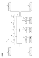
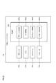
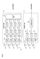
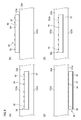
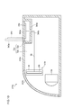
- the schematic diagram of the vehicle which comprises the vehicle system which concerns on 1st Embodiment of this invention is shown. It is a block diagram showing a vehicle system concerning a 1st embodiment. It is a block diagram which shows the left front sensing system. It is a block diagram which shows the structure of a millimeter wave radar. It is a figure which shows the structure of a transmission side RF circuit and a reception side RF circuit.
- A) is a front view of the antenna part provided with the transmitting antenna and the receiving antenna.
- (B) is an AA cross-sectional view of the antenna section shown in (a). It is a vertical cross-sectional view which shows the left front lamp equipped with a millimeter wave radar.
- FIG. 1D is a diagram showing an antenna portion according to a modified example arranged inside the outer cover. It is a vertical cross-sectional view which shows the left front lamp which concerns on the 2nd Embodiment equipped with the millimeter wave radar. It is a vertical cross-sectional view which shows the left front lamp which concerns on the 1st modification which mounted the millimeter wave radar. It is a vertical cross-sectional view which shows the left front lamp which concerns on the 2nd modification which mounted the millimeter wave radar.
- the “front-rear direction” is a direction including the “front direction” and the “rear direction”.
- the “left-right direction” is a direction including the “left direction” and the “right direction”.
- the “vertical direction” is a direction including "upward direction” and "downward direction”. Although the vertical direction is not shown in FIG. 1, the vertical direction is a direction perpendicular to the front-back direction and the left-right direction.
- FIG. 1 is a schematic diagram showing a top view of a vehicle 1 including a vehicle system 2.
- FIG. 2 is a block diagram showing the vehicle system 2.
- a vehicle 1 is a vehicle (automobile) capable of traveling in an automatic driving mode, and includes a vehicle system 2, a left front lamp 7a, a right front lamp 7b, a left rear lamp 7c, and a right rear lamp. 7d and.
- the vehicle system 2 includes a vehicle control unit 3, a left front sensing system 4a (hereinafter, simply referred to as “sensing system 4a”), and a right front sensing system 4b (hereinafter, simply “sensing system”). 4b ”), a left rear sensing system 4c (hereinafter, simply referred to as“ sensing system 4c ”), and a right rear sensing system 4d (hereinafter, simply referred to as“ sensing system 4d ”) are provided at least.
- a left front sensing system 4a hereinafter, simply referred to as “sensing system 4a”
- a right front sensing system 4b hereinafter, simply “sensing system”. 4b ”
- 4c left rear sensing system 4c
- a right rear sensing system 4d hereinafter, simply referred to as“ sensing system 4d ”
- the vehicle system 2 includes a sensor 5, an HMI (Human Machine Interface) 8, a GPS (Global Positioning System) 9, a wireless communication unit 10, and a storage device 11.
- the vehicle system 2 also includes a steering actuator 12, a steering device 13, a brake actuator 14, a brake device 15, an accelerator actuator 16, and an accelerator device 17.
- the vehicle control unit 3 is configured to control the traveling of the vehicle 1.
- the vehicle control unit 3 is composed of, for example, at least one electronic control unit (ECU: Electronic Control Unit).
- the electronic control unit includes a computer system (for example, SoC (System on a Chip)) including one or more processors and one or more memories, and an electronic circuit including active elements such as transistors and passive elements.
- the processor includes, for example, at least one of a CPU (Central Processing Unit), an MPU (Micro Processing Unit), a GPU (Graphics Processing Unit), and a TPU (Tensor Processing Unit).
- the CPU may be composed of a plurality of CPU cores.
- the GPU may be composed of a plurality of GPU cores.
- the memory includes a ROM (Read Only Memory) and a RAM (Random Access Memory).
- a vehicle control program may be stored in the ROM.
- the vehicle control program may include an artificial intelligence (AI) program for autonomous driving.
- the AI program is a program (learned model) constructed by supervised or unsupervised machine learning (in particular, deep learning) using a multilayer neural network.
- a vehicle control program, vehicle control data, and/or surrounding environment information indicating a surrounding environment of the vehicle may be temporarily stored in the RAM.
- the processor may be configured to expand a program designated from various vehicle control programs stored in the ROM on the RAM and execute various processes in cooperation with the RAM.
- the computer system may be configured by a non-Von Neumann computer such as an ASIC (Application Specific Integrated Circuit) or an FPGA (Field-Programmable Gate Array). Further, the computer system may be composed of a combination of a von Neumann computer and a non-Von Neumann computer.
- a non-Von Neumann computer such as an ASIC (Application Specific Integrated Circuit) or an FPGA (Field-Programmable Gate Array).
- the computer system may be composed of a combination of a von Neumann computer and a non-Von Neumann computer.
- Each of the sensing systems 4a to 4d is configured to detect the surrounding environment of the vehicle 1. In the description of this embodiment, it is assumed that each of the sensing systems 4a to 4d has the same constituent element. Therefore, in the following, the sensing system 4a will be described with reference to FIG. FIG. 3 is a block diagram showing the sensing system 4a.
- the sensing system 4a includes a control unit 40a, a lighting unit 42a, a camera 43a, a LiDAR (Light Detection and Ringing) unit 44a, and a millimeter-wave radar 45a.
- the control unit 40a, the lighting unit 42a, the camera 43a, the LiDAR unit 44a, and the millimeter wave radar 45a are provided in the space Sa formed by the housing 24a of the left front lamp 7a and the translucent outer cover 22a shown in FIG. Is located in.
- the control unit 40a may be arranged at a predetermined place of the vehicle 1 other than the space Sa.
- the control unit 40a may be integrally configured with the vehicle control unit 3.
- the control unit 40a is configured to control the operations of the illumination unit 42a, the camera 43a, the LiDAR unit 44a, and the millimeter wave radar 45a.
- the control unit 40a functions as the illumination unit control unit 420a, the camera control unit 430a, the LiDAR unit control unit 440a, and the millimeter wave radar control unit 450a.
- the control unit 40a is composed of at least one electronic control unit (ECU).
- the electronic control unit includes a computer system (for example, SoC or the like) including one or more processors and one or more memories, and an electronic circuit including active elements such as transistors and passive elements.
- the processor includes at least one of CPU, MPU, GPU and TPU.
- the memory includes a ROM and a RAM.
- the computer system may be composed of a non-Von Neumann computer such as an ASIC or FPGA.
- the lighting unit 42a is configured to form a light distribution pattern by emitting light toward the outside (front) of the vehicle 1.
- the lighting unit 42a has a light source that emits light and an optical system.
- the light source may be composed of, for example, a plurality of light emitting elements arranged in a matrix (for example, N rows ⁇ M columns, N> 1, M> 1).
- the light emitting element is, for example, an LED (Light Emitting Diode), an LD (LaSer Diode), or an organic EL element.
- the optical system is configured to reflect the light emitted from the light source toward the front of the illumination unit 42a, and to refract the light directly emitted from the light source or the light reflected by the reflector. At least one of the lens and the lens may be included.
- the lighting unit control unit 420a is configured to control the lighting unit 42a so that the lighting unit 42a emits a predetermined light distribution pattern toward the front region of the vehicle 1.
- the lighting unit control unit 420a may change the light distribution pattern emitted from the lighting unit 42a according to the driving mode of the vehicle 1.
- the camera 43a is configured to detect the surrounding environment of the vehicle 1.
- the camera 43a is configured to acquire image data indicating the surrounding environment of the vehicle 1 and then transmit the image data to the camera control unit 430a.
- the camera control unit 430a may specify the surrounding environment information based on the transmitted image data.
- the surrounding environment information may include information on an object existing outside the vehicle 1.
- the surrounding environment information may include information about the attribute of an object existing outside the vehicle 1 and information about the distance, direction, and/or position of the object with respect to the vehicle 1.
- the camera 43a includes, for example, an image sensor such as a CCD (Charge-Coupled Device) or a CMOS (Complementary MOS: Metal Oxide Semiconductor).
- the LiDAR unit 44a is configured to detect the surrounding environment of the vehicle 1. Particularly, the LiDAR unit 44a is configured to acquire the point cloud data indicating the surrounding environment of the vehicle 1 and then transmit the point cloud data to the LiDAR unit control unit 440a.
- the LiDAR unit controller 440a may specify the surrounding environment information based on the transmitted point cloud data.
- the LiDAR unit 44a acquires information regarding the time-of-flight (TOF: Time of Flight) ⁇ T1 of the laser light (light pulse) at each emission angle (horizontal angle ⁇ , vertical angle ⁇ ) of the laser light.
- TOF Time of Flight
- the LiDAR unit 44a can acquire information about the distance D between the LiDAR unit 44a at each emission angle and an object existing outside the vehicle 1 based on the information about the flight time ⁇ T1 at each emission angle.
- the millimeter wave radar 45a is configured to detect radar data indicating the surrounding environment of the vehicle 1.
- the millimeter-wave radar 45a is configured to acquire radar data and then transmit the radar data to the millimeter-wave radar control unit 450a.
- the millimeter wave radar control unit 450a is configured to acquire the surrounding environment information based on the radar data.
- the surrounding environment information may include information about an object existing outside the vehicle 1.
- the surrounding environment information may include, for example, information on the position and direction of the object with respect to the vehicle 1 and information on the relative speed of the object with respect to the vehicle 1.
- the millimeter wave radar 45a is a pulse modulation method, an FM-CW (Frequency Modulated-Continuous Wave) method, or a dual frequency CW method, and is a distance and direction between the millimeter wave radar 45a and an object existing outside the vehicle 1. Can be obtained.
- the pulse modulation method is used, the millimeter wave radar 45a acquires information about the flight time ⁇ T2 of the millimeter wave, and then, based on the information about the flight time ⁇ T2, the millimeter wave radar 45a and an object existing outside the vehicle 1. Information about the distance D between can be obtained.
- the millimeter wave radar 45a is arranged between the phase of the millimeter wave (reception wave) received by one reception antenna and the phase of the millimeter wave (reception wave) received by the other reception antenna adjacent to the one reception antenna. Information on the direction of the object with respect to the vehicle 1 can be acquired based on the phase difference. Further, the millimeter wave radar 45a acquires information on the relative velocity V of the object with respect to the millimeter wave radar 45a based on the frequency f0 of the transmitted wave emitted from the transmitting antenna and the frequency f1 of the received wave received by the receiving antenna. be able to. The specific structure of the millimeter wave radar 45a will be described later.
- each of the sensing systems 4b to 4d similarly includes a control unit, an illumination unit, a camera, a LiDAR unit, and a millimeter wave radar.
- these devices of the sensing system 4b are arranged in the space Sb formed by the housing 24b of the right front lamp 7b and the translucent outer cover 22b shown in FIG.
- These devices of the sensing system 4c are arranged in a space Sc formed by the housing 24c of the left rear lamp 7c and the translucent outer cover 22c.
- These devices of the sensing system 4d are arranged in a space Sd formed by the housing 24d of the right rear lamp 7d and the translucent outer cover 22d.
- the senor 5 may include an acceleration sensor, a speed sensor, a gyro sensor, and the like.
- the sensor 5 is configured to detect the running state of the vehicle 1 and output running state information indicating the running state of the vehicle 1 to the vehicle control unit 3. Further, the sensor 5 may have an outside air temperature sensor that detects the outside air temperature of the vehicle 1.
- the HMI 8 is composed of an input unit that receives an input operation from the driver and an output unit that outputs driving information and the like to the driver.
- the input unit includes a steering wheel, an accelerator pedal, a brake pedal, an operation mode changeover switch for changing over the operation mode of the vehicle 1, and the like.
- the output unit is a display (for example, Head Up Display (HUD) or the like) that displays various driving information.
- the GPS 9 is configured to acquire the current position information of the vehicle 1 and output the acquired current position information to the vehicle control unit 3.
- the wireless communication unit 10 is configured to receive information about other vehicles around the vehicle 1 from the other vehicle and transmit information about the vehicle 1 to the other vehicle (vehicle-to-vehicle communication). Further, the wireless communication unit 10 is configured to receive infrastructure information from infrastructure equipment such as traffic lights and indicator lights and to transmit traveling information of vehicle 1 to the infrastructure equipment (road-to-vehicle communication). Further, the wireless communication unit 10 receives information about the pedestrian from the portable electronic device (smartphone, tablet, wearable device, etc.) carried by the pedestrian, and transmits the own vehicle traveling information of the vehicle 1 to the portable electronic device. It is configured to do (communication between pedestrians). The vehicle 1 may directly communicate with another vehicle, infrastructure equipment, or a portable electronic device in an ad hoc mode, or may communicate with a communication network such as the Internet.
- a communication network such as the Internet.
- the storage device 11 is an external storage device such as a hard disk drive (HDD) or SSD (Solid State Drive).
- the storage device 11 may store two-dimensional or three-dimensional map information and/or a vehicle control program.
- the three-dimensional map information may be composed of 3D mapping data (point cloud data).
- the storage device 11 is configured to output map information and a vehicle control program to the vehicle control unit 3 in response to a request from the vehicle control unit 3.
- the map information and the vehicle control program may be updated via the wireless communication unit 10 and the communication network.
- the vehicle control unit 3 uses at least the steering control signal, the accelerator control signal, and the brake control signal based on the traveling state information, the surrounding environment information, the current position information, the map information, and the like. Generate one automatically.
- the steering actuator 12 is configured to receive a steering control signal from the vehicle control unit 3 and control the steering device 13 based on the received steering control signal.
- the brake actuator 14 is configured to receive a brake control signal from the vehicle control unit 3 and control the brake device 15 based on the received brake control signal.
- the accelerator actuator 16 is configured to receive an accelerator control signal from the vehicle control unit 3 and control the accelerator device 17 based on the received accelerator control signal.
- the vehicle control unit 3 automatically controls the travel of the vehicle 1 based on the travel state information, the surrounding environment information, the current position information, the map information, and the like. That is, in the automatic driving mode, the traveling of the vehicle 1 is automatically controlled by the vehicle system 2.
- the vehicle control unit 3 when the vehicle 1 travels in the manual driving mode, the vehicle control unit 3 generates a steering control signal, an accelerator control signal, and a brake control signal according to the manual operation of the driver on the accelerator pedal, the brake pedal, and the steering wheel.
- the steering control signal, the accelerator control signal, and the brake control signal are generated by the manual operation of the driver, so that the traveling of the vehicle 1 is controlled by the driver.
- FIG. 4 is a block diagram showing the configuration of the millimeter wave radar 45a.
- the millimeter wave radar 45a includes an antenna unit 56 and a communication circuit unit 50.
- the antenna unit 56 includes a plurality of transmitting antennas 54 configured to radiate millimeter waves, which are radio waves having a wavelength of 1 mm to 10 mm, and a plurality of receiving antennas 55 configured to receive millimeter waves.
- the radiated radio wave radiated from the transmitting antenna 54 is reflected by the object P, and then the reflected radio wave from the object P is received by the receiving antenna 55.
- the transmitting antenna 54 may be configured as, for example, a patch antenna.
- each of the nine transmitting antennas 54 is configured as a patch antenna (metal pattern) made of a conductive material.
- three transmitting antennas 54 are arranged in the D1 direction (column direction), and three transmitting antennas 54 are arranged in the D2 direction (row direction).
- the transmitting antenna group including each of the three transmitting antennas 54 is 54a, 54b, 54c, respectively, the phase of the high frequency signal supplied to the three transmitting antenna groups 54a, 54b, 54c arranged in the D2 direction is changed.
- the phase of the high frequency signal supplied to the three transmitting antenna groups 54a, 54b, 54c arranged in the D2 direction is changed.
- the beam direction of the synthetic radio wave can be changed without mechanically rotating the antenna portion 56.
- the receiving antenna 55 may also be similarly configured as a patch antenna.
- each of the 12 receiving antennas 55 is configured as a patch antenna made of a conductive material.
- three receiving antennas 55 are arranged in the D1 direction, and four receiving antennas 55 are arranged in the D2 direction. In this way, the directivity of the receiving antenna 55 in the D1 direction and the D2 direction can be improved.
- the antenna portion 56 further includes an insulating substrate 60 made of an insulating material and a ground electrode 57.
- the transmitting antenna 54 and the receiving antenna 55 are formed as patch antennas on the upper surface 62 of the insulating substrate 60, and the ground electrode 57 is formed on the lower surface 63 of the insulating substrate 60.
- the antenna unit 56 is configured as an antenna substrate including a receiving antenna and a transmitting antenna.
- the communication circuit unit 50 includes a transmitter RF (radio frequency) circuit 51, a receiver RF circuit 52, and a signal processing circuit 53.
- the communication circuit unit 50 is configured as a monolithic microwave integrated circuit (MMIC).
- the transmission side RF circuit 51 is electrically connected to each transmission antenna 54.
- the receiving RF circuit 52 is electrically connected to each receiving antenna 55.
- the signal processing circuit 53 is configured to control the transmitting-side RF circuit 51 and the receiving-side RF circuit 52 according to the control signal from the millimeter wave radar control unit 450a. Further, the signal processing circuit 53 generates radar data by processing the digital signal output from the receiving side RF circuit 52, and then transmits the generated radar data to the millimeter wave radar control unit 450a. It is configured.
- the signal processing circuit 53 includes, for example, a DSP (Digital Signal Processor) configured to process the digital signal transmitted from the reception side RF circuit 52, and a microcomputer including a processor and a memory.
- DSP Digital Signal Processor
- FIG. 5 is a diagram showing a configuration of a transmitting side RF circuit 51 and a receiving side RF circuit 52.
- the transmitting side RF circuit 51 includes a high frequency generating circuit 150, a phase device 152, and an amplifier 153.
- the high frequency generation circuit 150 is configured to generate a high frequency signal.
- the high-frequency generation circuit 150 when the millimeter-wave radar 45a is a millimeter-wave radar adopting the FMCW method, the high-frequency generation circuit 150 generates a chirp signal (FMCW signal) whose frequency changes linearly with the passage of time. ..
- Each of the phase shifters 152 is configured to adjust the phase of the high frequency signal output from the high frequency generation circuit 150. In this way, by adjusting the phase of the high frequency signal by each phase device 152, it is possible to change the beam direction in the horizontal direction of the combined radio wave of the radiated radio wave radiated from the plurality of transmitting antennas 54. In this respect, the phase difference between the high-frequency signal that has passed through the upper phase device 152 and the high-frequency signal that has passed through the middle-stage phase device 152, and the high-frequency signal that has passed through the middle-stage phase device 152 and the lower-stage phase device 152 have passed. The horizontal beam direction of the composite radio wave can be changed according to the phase difference from the high frequency signal.
- each phase shifter 152 does not adjust the phase of the high frequency signal, the beam direction of the combined radio wave of the radiated radio wave does not change. If the millimeter-wave radar 45a is not a phased array radar, the transmission side RF circuit 51 may not be provided with the phase device 152.
- the amplifier 153 is configured to amplify the high frequency signal that has passed through the phase shifter 152. By supplying the high-frequency signal amplified by the amplifier 153 to each transmitting antenna 54 in this way, each transmitting antenna 54 radiates radio waves (millimeter waves) corresponding to the high-frequency signal into the air.
- the receiving side RF circuit 52 includes an amplifier 154, a mixer 155, a bandpass filter (BPF) 156, an AD converter 157, and a filter circuit 158.
- the amplifier 154 is configured to amplify the high frequency signal output from the reception antenna 55.
- the receiving antenna 55 receives the reflected radio wave reflected by the object and then converts the received reflected radio wave into a high frequency signal.
- the amplifier 154 amplifies the weak high frequency signal output by the receiving antenna 55.
- the mixer 155 mixes the high frequency signal (RX signal) output from the amplifier 154 and the high frequency signal (TX signal) from the high frequency generation circuit 150 to generate an intermediate frequency (IF) signal (also referred to as a beat frequency signal). To generate.
- IF intermediate frequency
- the IF signal (analog signal) that has passed through the BPF 156 is converted from the analog signal to the digital signal by the AD converter 157.
- the digital signal is transmitted to the signal processing circuit 53 via the filter circuit 158.
- the signal processing circuit 53 performs fast Fourier transform (FFT) on the digital signal (IF signal) to generate radar data indicating the position and relative velocity of the target object.
- FFT fast Fourier transform
- FIG. 7 is a vertical cross-sectional view showing the left front lamp 7a on which the millimeter wave radar 45a is mounted.
- the illustration of a device other than the millimeter wave radar 45a (for example, a lighting unit 42a or the like) is omitted.
- the space Sa is formed by the housing 24a and the outer cover 22a covering the opening of the housing 24a.
- One end of the outer cover 22a is fixed to the housing 24a via a metal fixing member 73, and the other end of the outer cover 22a is fixed to the housing 24a via a metal fixing member 72.
- the metal fixing members 72, 73 are, for example, screws, rivets or springs.
- the communication circuit unit 50 of the millimeter wave radar 45a is arranged in the space Sa.
- the communication circuit unit 50 is arranged on the surface of the housing 24a in the space Sa.
- the antenna section 56 of the millimeter wave radar 45a is provided inside the outer cover 22a.
- the transmitting antenna 54 and the receiving antenna 55 face the outer surface 123a of the outer cover 22a, while the ground electrode 57 faces the inner surface 122a of the outer cover 22a.
- the antenna portion 56 is provided inside the outer cover 22a so as to face each other. In this case, the transmitting antenna 54 can efficiently radiate the radiated radio wave toward the outside of the vehicle 1, and the receiving antenna 55 can efficiently receive the reflected radio wave.
- the communication circuit unit 50 and the antenna unit 56 are mounted on the left front lamp 7a in a state of being separated from each other.
- the antenna section 56 is electrically connected to the communication circuit section 50 via the metal fixing member 72 and the cable 70.
- the antenna unit 56 is provided inside the outer cover 22a, while the communication circuit unit 50 is arranged inside the space Sa. Therefore, the millimeter wave radar 45a can be successfully mounted on the left front lamp 7a without reducing the outer size of the antenna section 56 and/or the communication circuit section 50 of the millimeter wave radar 45a.
- the antenna portion 56 and the communication circuit portion 50 can be electrically connected by using the metal fixing member 72 that fixes the outer cover 22a and the housing 24a.
- the antenna portion 56 is provided inside the outer cover 22a, but the present embodiment is not limited to this.
- the antenna portion 56 may be arranged on the outer surface 123a of the outer cover 22a.
- the antenna portion 56 may be arranged on the inner surface 122a of the outer cover 22a.
- the insulating substrate 60 constituting the antenna portion 56 may be replaced with a part 220a of the outer cover 22a.
- the antenna portion 56x according to the modified example is the ground electrode 57 facing the transmitting antenna 54 and the receiving antenna 55 via the transmitting antenna 54, the receiving antenna 55, a part 220a of the outer cover 22a, and a part 220a.
- FIG. 9 is a vertical cross-sectional view showing the left front lamp 170a on which the millimeter wave radar 145a is mounted. Note that, in this figure, for convenience of description, devices other than the millimeter wave radar 145a and the illumination unit 42a (for example, a camera, a LiDAR unit, etc.) are not shown.
- the millimeter wave radar 145a of the present embodiment has the same configuration as the millimeter wave radar 45a of the first embodiment.
- the antenna unit 256 of the millimeter wave radar 145a has the same configuration as the antenna unit 56 of the first embodiment.
- the communication circuit unit 250 of the millimeter wave radar 145a has the same configuration as the communication circuit unit 50 of the first embodiment.
- a space S a0 is formed by the housing 124a of the left front lamp 170a and the outer cover 222a that covers the opening of the housing 124a.
- the left front lamp 170a is provided with a plate-shaped partition member 245a.
- the partition member 245a is configured to partition the space S a0 into a first space S a1 and a second space S a2 .
- the antenna unit 256 of the millimeter wave radar 145a and the lighting unit 42a are arranged in the first space S a1 .
- the antenna unit 256 is arranged in the first space S a1 so that the transmitting antenna and the receiving antenna face the outer cover 222a.
- the transmitting antenna can efficiently radiate the radiated radio wave to the outside of the vehicle 1, and the receiving antenna can efficiently receive the reflected radio wave.
- the antenna portion 256 is packed by the radome 58.
- the camera and the LiDAR unit are not shown in the figure, it is assumed that the camera and the LiDAR unit are also arranged in the first space S a1 .
- the communication circuit section 250 of the millimeter wave radar 145a is arranged in the second space S a2 .
- the communication circuit section 250 is electrically connected to the antenna section 256 via the electric cable 59.
- the partition member 245a is provided with an opening 246a that allows passage of the electric cable 59.
- the electric cable 59 may be, for example, a coaxial cable.
- the housing 124a is provided with an opening 242a communicating with the external space and the second space S a2, and a lid 243a configured to close the opening 242a.
- the lid 243a is closed during normal use of the left front lamp 170a.
- millimeter wave radar 145a (in particular, the communication circuit unit 250) when there is an abnormality, the operator, the left front lamp the communication circuit unit 250 disposed in the second space S a2 by opening the lid 243a It can be quickly removed from 170a.
- the lid 243a improves the handling of the millimeter wave radar 145a.
- the antenna unit 256 and the communication circuit unit 250 of the millimeter wave radar 145a are arranged in the space S a0 while being physically separated from each other. Therefore, the millimeter wave radar 145a can be successfully mounted on the left front lamp 170a without downsizing the millimeter wave radar 145a. Further, the antenna unit 256 and the lighting unit 42a are arranged in the first space S a1 , while the communication circuit unit 250 is arranged in the second space S a2 . Therefore, it is possible to preferably prevent the communication circuit unit 250 from being adversely affected by the heat generated from the lighting unit 42a.
- the antenna part 256 may not be packed by the radome 58.
- the antenna unit 256 may be transparent to visible light.
- the insulating substrate may be, for example, a glass substrate that is transparent to visible light.
- the transmitting antenna and the receiving antenna may be configured as, for example, a patch antenna made of a transparent conductive material.
- the transparent conductive material for example, ITO (indium, tin oxide) which is a transparent conductive film may be used.
- the antenna portion 256 is transparent to visible light, the antenna portion 256 becomes difficult to see from the outside of the vehicle 1, and the design of the left front lamp 170a equipped with the millimeter wave radar 145a can be improved. it can.
- FIG. 10 is a vertical cross-sectional view showing a left front lamp 270a according to a first modification in which the millimeter wave radar 145a is mounted.
- the left front lamp 270a shown in FIG. 10 and the left front lamp 170a shown in FIG. 9 differ from each other mainly in the configuration of the partition member.
- a space S ra is formed by the housing 224a and the outer cover 222a that covers the opening of the housing 224a.
- the front left lamp 270a is provided with a partition member 345a that surrounds the communication circuit unit 250.
- the partition member 345a is configured to partition the space S ra into a first space S a3 and a second space S a4 .
- the antenna unit 256 and the lighting unit 42a are arranged in the first space S a3 .
- the antenna unit 256 is arranged in the first space S a3 so that the transmitting antenna and the receiving antenna face the outer cover 222a.
- the camera and the LiDAR unit are not shown, but it is assumed that the camera and the LiDAR unit are also arranged in the first space S a3 .
- the communication circuit unit 250 is arranged in the second space Sa4 .
- the communication circuit section 250 is arranged on the lid section 343a provided on the housing 224a.
- the communication circuit section 250 is electrically connected to the antenna section 256 via the electric cable 59.
- the partition member 345a is provided with an opening 346a that allows passage of the electric cable 59.
- the antenna unit 256 and the communication circuit unit 250 are arranged in the space S ra in a state where they are physically separated from each other. Therefore, it is possible to successfully mount the millimeter wave radar 145a on the left front lamp 270a without downsizing the millimeter wave radar 145a. Further, the antenna unit 256 and the lighting unit 42a are arranged in the first space S a3 , while the communication circuit unit 250 is arranged in the second space S a4 . Therefore, it is possible to preferably prevent the communication circuit unit 250 from being adversely affected by the heat generated from the lighting unit 42a.
- the operator when there is an abnormality in the millimeter wave radar 145a (particularly, the communication circuit unit 250), the operator opens the lid portion 343a to perform communication arranged on the lid portion 343a.
- the circuit unit 250 can be easily taken out from the left front lamp 270a.
- the antenna portion 256 does not have to be packed by the radome 58.
- the antenna unit 256 may be transparent to visible light.
- FIG. 11 is a vertical cross-sectional view showing a left front lamp 370a according to a second modification in which the millimeter wave radar 345a is mounted.
- the left front lamp 370a shown in FIG. 11 differs from the left front lamp 170a shown in FIG. 9 in the configuration of the antenna unit 356 of the millimeter wave radar 345a. Only the configuration of the antenna unit 356 will be described below.
- the antenna part 356 is not packed by the radome, but is attached to the outer cover 222a. Further, the antenna portion 356 is transparent to visible light and has flexibility.
- the insulating substrate of the antenna unit 356 may be a flexible substrate made of a material transparent to visible light.
- the transmitting antenna and the receiving antenna of the antenna unit 356 may be configured as patch antennas made of a transparent conductive material, for example. ITO, for example, may be used as the transparent conductive material.
- an adhesive layer that contacts the outer cover 222a may be provided on the insulating substrate of the antenna unit 356.
- the antenna portion 356 is attached to the outer cover 222a, it is not necessary to secure a space for arranging the antenna portion 356 in the first space Sa1 . In this way, the degree of freedom in designing the left front lamp 370a can be improved, and the millimeter wave radar 345a can be successfully mounted in the left front lamp 370a without downsizing the millimeter wave radar 345a. Further, since the antenna portion 356 is transparent to visible light, the antenna portion 356 becomes difficult to see from the outside of the vehicle 1, and the design of the left front lamp 370a equipped with the millimeter wave radar 345a can be improved.
- the millimeter wave radar 45a has been described as an example of the radio wave transmitting/receiving module, but the radio wave transmitting/receiving module is not limited to the millimeter wave radar.
- the radio wave transmitting/receiving module may be a wireless communication module (wireless communication unit 10) configured to wirelessly communicate with an external device.
- the wireless communication module may be a wireless communication module for a fifth generation (5G) mobile communication system.
- the antenna portion of the wireless communication module is provided on the outer cover 22a of the left front lamp 7a.
- the communication circuit unit of the wireless communication module is arranged in the space Sa of the left front lamp 7a.
- the configurations of the communication circuit unit and the antenna unit of the wireless communication module may be different from the configurations of the communication circuit unit and the antenna unit of the millimeter wave radar.
- the communication circuit unit 250 is arranged in the space S a0 (particularly, the second space) of the left front lamp 170a, but the second embodiment is limited to this. It's not a thing.
- the communication circuit unit 250 may be arranged outside the space Sa0 .
- the communication circuit unit 250 may be arranged outside the space Sa and on the outer surface of the housing 124a. In this case as well, the communication circuit section 250 can be preferably prevented from being adversely affected by the heat generated from the lighting unit 42a.
- Vehicle 2 Vehicle system 3: Vehicle control unit 4a: Left front sensing system 4b: Right front sensing system 4c: Left rear sensing system 4d: Right rear sensing system 5: Sensors 7a, 170a, 270a, 370a: Left front lamp 7b: Right front Lighting 7c: Left rear lighting 7d: Right rear lighting 10: Radio communication unit 11: Storage device 12: Steering actuator 13: Steering device 14: Brake actuator 15: Brake device 16: Accelerator actuator 17: Accelerator device 22a, 22b, 22c, 22d, 222a: Outer cover 24a, 24b, 24c, 24d, 124a: Housing 40a: Control unit 42a: Lighting unit 43a: Camera 44a: LiDAR unit 45a, 145a, 345a: Millimeter wave radar 50, 250: Communication circuit unit 51: Transmission side RF circuit 52: Reception side RF circuit 53: Signal processing circuit 54: Transmission antenna 55: Reception antennas 56, 56x, 256, 356: Antenna part 57
Landscapes
- Engineering & Computer Science (AREA)
- Physics & Mathematics (AREA)
- Radar, Positioning & Navigation (AREA)
- Remote Sensing (AREA)
- General Physics & Mathematics (AREA)
- Computer Networks & Wireless Communication (AREA)
- Mechanical Engineering (AREA)
- Electromagnetism (AREA)
- General Engineering & Computer Science (AREA)
- Mathematical Physics (AREA)
- Microelectronics & Electronic Packaging (AREA)
- Optics & Photonics (AREA)
- Radar Systems Or Details Thereof (AREA)
- Traffic Control Systems (AREA)
Abstract
左前灯具(7a)は、ハウジング(24a)と、ハウジング(24a)の開口を覆うアウターカバー(22a)と、ミリ波レーダ(45a)とを備える。ミリ波レーダ(45a)は、アンテナ部(56)と、通信回路部(50)とを備える。アンテナ部(56)は、送信アンテナと、受信アンテナとを備える。通信回路部(50)は、前記送信アンテナに電気的に接続された送信側RF回路と、前記受信アンテナに電気的に接続された受信側RF回路と、前記受信側RF回路から出力されたデジタル信号を処理するように構成された信号処理回路とを備える。アンテナ部(56)は、アウターカバー(22a)の内部に設けられている。通信回路部(50)は、ハウジング(24a)とアウターカバー(22a)とによって形成された空間(Sa)内に配置されている。
Description
本開示は、車両用灯具及び車両に関する。
現在、自動車の自動運転技術の研究が各国で盛んに行われており、自動運転モードで車両(以下、「車両」は自動車のことを指す。)が公道を走行することができるための法整備が各国で検討されている。ここで、自動運転モードでは、車両システムが車両の走行を自動的に制御する。具体的には、自動運転モードでは、車両システムは、カメラ、レーダ(例えば、レーザレーダやミリ波レーダ)等のセンサから得られる車両の周辺環境を示す情報(周辺環境情報)に基づいてステアリング制御(車両の進行方向の制御)、ブレーキ制御及びアクセル制御(車両の制動、加減速の制御)のうちの少なくとも1つを自動的に行う。一方、以下に述べる手動運転モードでは、従来型の車両の多くがそうであるように、運転者が車両の走行を制御する。具体的には、手動運転モードでは、運転者の操作(ステアリング操作、ブレーキ操作、アクセル操作)に従って車両の走行が制御され、車両システムはステアリング制御、ブレーキ制御及びアクセル制御を自動的に行わない。尚、車両の運転モードとは、一部の車両のみに存在する概念ではなく、自動運転機能を有さない従来型の車両も含めた全ての車両において存在する概念であって、例えば、車両制御方法等に応じて分類される。
このように、将来において、公道上では自動運転モードで走行中の車両(以下、適宜、「自動運転車」という。)と手動運転モードで走行中の車両(以下、適宜、「手動運転車」という。)が混在することが予想される。
自動運転技術の一例として、特許文献1には、先行車に後続車が自動追従走行した自動追従走行システムが開示されている。当該自動追従走行システムでは、先行車と後続車の各々が照明システムを備えており、先行車と後続車との間に他車が割り込むことを防止するための文字情報が先行車の照明システムに表示されると共に、自動追従走行である旨を示す文字情報が後続車の照明システムに表示される。
ところで、自動運転技術の発展において、車両の周辺環境の検出精度を飛躍的に増大させる必要がある。この点において、車両の周辺環境を検出する複数のセンサ(例えば、カメラ、LiDARユニット、ミリ波レーダ等)を車両に搭載することで車両の周辺環境の検出精度を飛躍的に向上させることが可能となる。また、車両の外観やセンサ搭載スペースの観点より、複数のセンサを各車両用灯具内に搭載することが現在検討されている。
しかしながら、車両及び車両用灯具のデザイン上の制約の観点より複数のセンサを車両用灯具内に搭載することには種々の課題が存在する。例えば、車両及び車両用灯具のデザインによっては、センサの一つであるミリ波レーダ(電波送受信モジュールの一例)を車両用灯具内に首尾よく搭載することができないといった課題が存在する。この課題に対応するために、ミリ波レーダの外形サイズを小型化することが考えられるが、ミリ波レーダの小型化(特に、ミリ波レーダのアンテナ部の小型化)に伴い、ミリ波レーダの検出性能が低下する虞がある。このように、ミリ波レーダ等の電波送受信モジュールを小型化せずに、当該電波送受信モジュールを車両用灯具に首尾よく搭載するための手法について検討する余地がある。
本開示は、電波送受信モジュールのアンテナ部及び/又は通信回路部の外形サイズを小型化せずに、電波送受信モジュールを首尾よく車両用灯具に搭載することを目的とする。
本開示の一態様に係る車両用灯具は、ハウジングと、前記ハウジングの開口を覆うアウターカバーと、電波送受信モジュールとを備える。
前記電波送受信モジュールは、
送信アンテナと、受信アンテナとを備えたアンテナ部と、
前記送信アンテナに電気的に接続された送信側RF回路と、
前記受信アンテナに電気的に接続された受信側RF回路と、
前記受信側RF回路から出力されたデジタル信号を処理するように構成された信号処理回路と、を備えた通信回路部と、を備える。
前記アンテナ部は、前記アウターカバーに設けられている。前記通信回路部は、前記ハウジングと前記アウターカバーとによって形成された空間内に配置されている。
前記電波送受信モジュールは、
送信アンテナと、受信アンテナとを備えたアンテナ部と、
前記送信アンテナに電気的に接続された送信側RF回路と、
前記受信アンテナに電気的に接続された受信側RF回路と、
前記受信側RF回路から出力されたデジタル信号を処理するように構成された信号処理回路と、を備えた通信回路部と、を備える。
前記アンテナ部は、前記アウターカバーに設けられている。前記通信回路部は、前記ハウジングと前記アウターカバーとによって形成された空間内に配置されている。
上記構成によれば、アンテナ部がアウターカバーに設けられている一方で、通信回路部はハウジングとアウターカバーとによって形成された空間内に配置されている。このため、電波送受信モジュールのアンテナ部及び/又は通信回路部の外形サイズを小型化せずに、電波送受信モジュールを首尾よく車両用灯具に搭載することができる。
また、前記アンテナ部は、前記アウターカバーの内部に設けられてもよい。
上記構成によれば、アンテナ部がアウターカバーの内部に設けられているので、電波送受信モジュールのアンテナ部及び/又は通信回路部の外形サイズを小型化せずに、電波送受信モジュールを首尾よく車両用灯具に搭載することができる。
また、前記アンテナ部は、前記アウターカバーの表面上に設けられてもよい。
上記構成によれば、アンテナ部がアウターカバーの表面上に設けられているので、電波送受信モジュールのアンテナ部及び/又は通信回路部の外形サイズを小型化せずに、電波送受信モジュールを首尾よく車両用灯具に搭載することができる。
また、前記アンテナ部と前記通信回路部は、前記アウターカバーと前記ハウジングとを固定する金属固定部材を介して互いに電気的に接続されてもよい。
上記構成によれば、アウターカバーとハウジングとを固定する金属固定部材を用いてアンテナ部と通信回路部とを電気的に接続することができる。
また、前記電波送受信モジュールは、車両の周辺環境を示すデータを取得するように構成されたミリ波レーダであってもよい。
上記構成によれば、ミリ波レーダのアンテナ部及び/又は通信回路部の外形サイズを小型化せずに、ミリ波レーダを首尾よく車両用灯具に搭載することができる。
また、前記電波送受信モジュールは、外部装置と無線通信するように構成された無線通信モジュールであってもよい。
上記構成によれば、無線通信モジュールのアンテナ部及び/又は外形サイズを小型化せずに、無線通信モジュールを首尾よく車両用灯具に搭載することができる。
上記車両用灯具を備えた車両が提供されてもよい。
上記によれば、電波送受信モジュールのアンテナ部及び/又は通信回路の外形サイズを小型化せずに、電波送受信モジュールを首尾よく車両用灯具に搭載することができる。
また、本開示の別の態様に係る車両用灯具は、車両に搭載されており、
ハウジングと、
前記ハウジングの開口を覆うアウターカバーと、
前記ハウジングと前記アウターカバーとによって形成された空間内に配置された照明ユニットと、
前記車両の周辺環境を示すデータを取得するように構成されたミリ波レーダと、
を備える。
前記ミリ波レーダは、
送信アンテナと、受信アンテナとを有するアンテナ部と、
前記送信アンテナに電気的に接続された送信側RF回路と、
前記受信アンテナに電気的に接続された受信側RF回路と、
前記受信側RF回路から出力されたデジタル信号を処理するように構成された信号処理回路と、を有する通信回路部と、を備える。
前記アンテナ部と前記通信回路部とは互いに物理的に分離されている。
前記アンテナ部は、前記空間内に配置されている。
ハウジングと、
前記ハウジングの開口を覆うアウターカバーと、
前記ハウジングと前記アウターカバーとによって形成された空間内に配置された照明ユニットと、
前記車両の周辺環境を示すデータを取得するように構成されたミリ波レーダと、
を備える。
前記ミリ波レーダは、
送信アンテナと、受信アンテナとを有するアンテナ部と、
前記送信アンテナに電気的に接続された送信側RF回路と、
前記受信アンテナに電気的に接続された受信側RF回路と、
前記受信側RF回路から出力されたデジタル信号を処理するように構成された信号処理回路と、を有する通信回路部と、を備える。
前記アンテナ部と前記通信回路部とは互いに物理的に分離されている。
前記アンテナ部は、前記空間内に配置されている。
上記構成によれば、ミリ波レーダのアンテナ部と通信回路部が互いに分離されているので、ミリ波レーダを小型化せずに、ミリ波レーダを首尾よく車両用灯具に搭載することができる。
また、車両用灯具は、前記空間を第1空間と第2空間に区画するように構成された仕切り部材をさらに備えてもよい。前記アンテナ部及び前記照明ユニットは、前記第1空間内に配置されてもよい。前記通信回路部は、前記第2空間内に配置されてもよい。
上記構成によれば、アンテナ部と照明ユニットが第1空間に配置されている一方で、通信回路部が第2空間内に配置されている。このため、照明ユニットから発生した熱によって通信回路部が悪影響を受けることが好適に防止されうる。
また、前記ハウジングは、開口部と、前記開口部を塞ぐように構成された蓋部とを有してもよい。前記通信回路部は、前記蓋部上に配置されてもよい。
上記構成によれば、通信回路部がハウジングの蓋部上に配置されているので、通信回路部を容易に車両用灯具から取り出すことができる。このため、通信回路部に異常がある場合に、通信回路部を素早く車両用灯具から取り出すことができるため、車両用灯具に搭載されたミリ波レーダの取り扱い性が向上する。
また、前記通信回路部は、前記空間の外側に配置されてもよい。
上記構成によれば、通信回路部が空間の外側に配置されているため、照明ユニットから発生した熱によって通信回路部が悪影響を受けることが好適に防止されうる。
また、前記アンテナ部は、前記アウターカバーに貼り付けられていてもよい。
上記構成によれば、アンテナ部がアウターカバーに貼り付けられているため、アンテナ部を配置するための空間を灯具内に確保する必要がない。このように、車両用灯具の設計自由度を向上させることができると共に、ミリ波レーダを小型化せずにミリ波レーダを首尾よく車両用灯具内に搭載することができる。
また、アンテナ部は可視光に対して透明であってもよい。
上記構成によれば、アンテナ部が可視光に対して透明であるため、アンテナ部が車両の外部から視認し難くなる。このように、ミリ波レーダを搭載した車両用灯具のデザイン性を向上させることができる。
上記車両用灯具を備えた車両が提供されてもよい。
上記によれば、ミリ波レーダを小型化せずに、ミリ波レーダを首尾よく車両用灯具に搭載することができる。
本開示によれば、電波送受信モジュールのアンテナ部及び/又は通信回路部の外形サイズを小型化せずに、電波送受信モジュールを首尾よく車両用灯具に搭載することができる。
(第1実施形態)
以下、本開示の第1実施形態(以下、単に「本実施形態」という。)について図面を参照しながら説明する。尚、本実施形態の説明において既に説明された部材と同一の参照番号を有する部材については、説明の便宜上、その説明は省略する。また、本図面に示された各部材の寸法は、説明の便宜上、実際の各部材の寸法とは異なる場合がある。
以下、本開示の第1実施形態(以下、単に「本実施形態」という。)について図面を参照しながら説明する。尚、本実施形態の説明において既に説明された部材と同一の参照番号を有する部材については、説明の便宜上、その説明は省略する。また、本図面に示された各部材の寸法は、説明の便宜上、実際の各部材の寸法とは異なる場合がある。
また、本実施形態の説明では、説明の便宜上、「左右方向」、「前後方向」、「上下方向」について適宜言及する場合がある。これらの方向は、図1に示す車両1について設定された相対的な方向である。ここで、「前後方向」は、「前方向」及び「後方向」を含む方向である。「左右方向」は、「左方向」及び「右方向」を含む方向である。「上下方向」は、「上方向」及び「下方向」を含む方向である。尚、図1では上下方向は示されていないが、上下方向は、前後方向及び左右方向に垂直な方向である。
最初に、図1及び図2を参照して本実施形態に係る車両1及び車両システム2について説明する。図1は、車両システム2を備える車両1の上面図を示す模式図である。図2は、車両システム2を示すブロック図である。
図1に示すように、車両1は、自動運転モードで走行可能な車両(自動車)であって、車両システム2と、左前灯具7aと、右前灯具7bと、左後灯具7cと、右後灯具7dとを備える。
図1及び図2に示すように、車両システム2は、車両制御部3と、左前センシングシステム4a(以下、単に「センシングシステム4a」という。)と、右前センシングシステム4b(以下、単に「センシングシステム4b」という。)と、左後センシングシステム4c(以下、単に「センシングシステム4c」という。)と、右後センシングシステム4d(以下、単に「センシングシステム4d」という。)を少なくとも備える。
さらに、車両システム2は、センサ5と、HMI(Human Machine Interface)8と、GPS(Global Positioning System)9と、無線通信部10と、記憶装置11とを備える。また、車両システム2は、ステアリングアクチュエータ12と、ステアリング装置13と、ブレーキアクチュエータ14と、ブレーキ装置15と、アクセルアクチュエータ16と、アクセル装置17とを備える。
車両制御部3は、車両1の走行を制御するように構成されている。車両制御部3は、例えば、少なくとも一つの電子制御ユニット(ECU:Electronic Control Unit)により構成されている。電子制御ユニットは、1以上のプロセッサと1以上のメモリを含むコンピュータシステム(例えば、SoC(System on a Chip)等)と、トランジスタ等のアクティブ素子及びパッシブ素子から構成される電子回路を含む。プロセッサは、例えば、CPU(Central Processing Unit)、MPU(Micro Processing Unit)、GPU(Graphics Processing Unit)及びTPU(Tensor Processing Unit)のうちの少なくとも一つを含む。CPUは、複数のCPUコアによって構成されてもよい。GPUは、複数のGPUコアによって構成されてもよい。メモリは、ROM(Read Only Memory)と、RAM(Random Access Memory)を含む。ROMには、車両制御プログラムが記憶されてもよい。例えば、車両制御プログラムは、自動運転用の人工知能(AI)プログラムを含んでもよい。AIプログラムは、多層のニューラルネットワークを用いた教師有り又は教師なし機械学習(特に、ディープラーニング)によって構築されたプログラム(学習済みモデル)である。RAMには、車両制御プログラム、車両制御データ及び/又は車両の周辺環境を示す周辺環境情報が一時的に記憶されてもよい。プロセッサは、ROMに記憶された各種車両制御プログラムから指定されたプログラムをRAM上に展開し、RAMとの協働で各種処理を実行するように構成されてもよい。また、コンピュータシステムは、ASIC(Application Specific Integrated Circuit)やFPGA(Field-Programmable Gate Array)等の非ノイマン型コンピュータによって構成されてもよい。さらに、コンピュータシステムは、ノイマン型コンピュータと非ノイマン型コンピュータの組み合わせによって構成されてもよい。
センシングシステム4a~4dの各々は、車両1の周辺環境を検出するように構成されている。本実施形態の説明では、センシングシステム4a~4dの各々は、同一の構成要素を備えるものとする。このため、以下では、センシングシステム4aについて図3を参照して説明する。図3は、センシングシステム4aを示すブロック図である。
図3に示すように、センシングシステム4aは、制御部40aと、照明ユニット42aと、カメラ43aと、LiDAR(Light Detection and Ranging)ユニット44aと、ミリ波レーダ45aとを備える。制御部40aと、照明ユニット42aと、カメラ43aと、LiDARユニット44aと、ミリ波レーダ45aは、図1に示す左前灯具7aのハウジング24aと透光性のアウターカバー22aによって形成される空間Sa内に配置される。制御部40aは、空間Sa以外の車両1の所定の場所に配置されてもよい。例えば、制御部40aは、車両制御部3と一体的に構成されてもよい。
制御部40aは、照明ユニット42aと、カメラ43aと、LiDARユニット44aと、ミリ波レーダ45aの動作をそれぞれ制御するように構成されている。この点において、制御部40aは、照明ユニット制御部420a、カメラ制御部430a、LiDARユニット制御部440a、ミリ波レーダ制御部450aとして機能する。
制御部40aは、少なくとも一つの電子制御ユニット(ECU)により構成されている。電子制御ユニットは、1以上のプロセッサと1以上のメモリを含むコンピュータシステム(例えば、SoC等)と、トランジスタ等のアクティブ素子及びパッシブ素子から構成される電子回路を含む。プロセッサは、CPU、MPU、GPU及びTPUのうちの少なくとも一つを含む。メモリは、ROMと、RAMを含む。また、コンピュータシステムは、ASICやFPGA等の非ノイマン型コンピュータによって構成されてもよい。
照明ユニット42aは、車両1の外部(前方)に向けて光を出射することによって、配光パターンを形成するように構成されている。照明ユニット42aは、光を出射する光源と、光学系とを有する。光源は、例えば、マトリックス状(例えば、N行×M列、N>1、M>1)に配列された複数の発光素子によって構成されてもよい。発光素子は、例えば、LED(Light Emitting Diode)、LD(LaSer Diode)又は有機EL素子である。光学系は、光源から出射された光を照明ユニット42aの前方に向けて反射するように構成されたリフレクタと、光源から直接出射された光又はリフレクタによって反射された光を屈折するように構成されたレンズとのうちの少なくとも一方を含んでもよい。
照明ユニット制御部420aは、照明ユニット42aが所定の配光パターンを車両1の前方領域に向けて出射するように照明ユニット42aを制御するように構成されている。例えば、照明ユニット制御部420aは、車両1の運転モードに応じて照明ユニット42aから出射される配光パターンを変更してもよい。
カメラ43aは、車両1の周辺環境を検出するように構成されている。特に、カメラ43aは、車両1の周辺環境を示す画像データを取得した上で、当該画像データをカメラ制御部430aに送信するように構成されている。カメラ制御部430aは、送信された画像データに基づいて、周辺環境情報を特定してもよい。ここで、周辺環境情報は、車両1の外部に存在する対象物に関する情報を含んでもよい。例えば、周辺環境情報は、車両1の外部に存在する対象物の属性に関する情報と、車両1に対する対象物の距離と方向及び/又は位置に関する情報とを含んでもよい。カメラ43aは、例えば、CCD(Charge-Coupled Device)やCMOS(相補型MOS:Metal Oxide Semiconductor)等の撮像素子を含む。
LiDARユニット44aは、車両1の周辺環境を検出するように構成されている。特に、LiDARユニット44aは、車両1の周辺環境を示す点群データを取得した上で、当該点群データをLiDARユニット制御部440aに送信するように構成されている。LiDARユニット制御部440aは、送信された点群データに基づいて、周辺環境情報を特定してもよい。
より具体的には、LiDARユニット44aは、レーザ光の各出射角度(水平角度θ、垂直角度φ)におけるレーザ光(光パルス)の飛行時間(TOF:Time of Flight)ΔT1に関する情報を取得する。LiDARユニット44aは、各出射角度における飛行時間ΔT1に関する情報に基づいて、各出射角度におけるLiDARユニット44aと車両1の外部に存在する物体との間の距離Dに関する情報を取得することができる。
ミリ波レーダ45aは、車両1の周辺環境を示すレーダデータを検出するように構成されている。特に、ミリ波レーダ45aは、レーダデータを取得した上で、当該レーダデータをミリ波レーダ制御部450aに送信するように構成されている。ミリ波レーダ制御部450aは、レーダデータに基づいて、周辺環境情報を取得するように構成されている。周辺環境情報は、車両1の外部に存在する対象物に関する情報を含んでもよい。周辺環境情報は、例えば、車両1に対する対象物の位置と方向に関する情報と、車両1に対する対象物の相対速度に関する情報を含んでもよい。
例えば、ミリ波レーダ45aは、パルス変調方式、FM‐CW(Frequency Moduleted‐Continuous Wave)方式又は2周波CW方式で、ミリ波レーダ45aと車両1の外部に存在する物体との間の距離及び方向を取得することができる。パルス変調方式を用いる場合、ミリ波レーダ45aは、ミリ波の飛行時間ΔT2に関する情報を取得した上で、飛行時間ΔT2に関する情報に基づいて、ミリ波レーダ45aと車両1の外部に存在する物体との間の距離Dに関する情報を取得することができる。また、ミリ波レーダ45aは、一方の受信アンテナで受信したミリ波(受信波)の位相と一方の受信アンテナに隣接する他方の受信アンテナで受信したミリ波(受信波)の位相との間の位相差に基づいて、車両1に対する物体の方向に関する情報を取得することができる。また、ミリ波レーダ45aは、送信アンテナから放射された送信波の周波数f0と受信アンテナで受信された受信波の周波数f1に基づいて、ミリ波レーダ45aに対する物体の相対速度Vに関する情報を取得することができる。ミリ波レーダ45aの具体的な構造については後述する。
また、センシングシステム4b~4dの各々も同様にして、制御部と、照明ユニットと、カメラと、LiDARユニットと、ミリ波レーダを備える。特に、センシングシステム4bのこれらの装置は、図1に示す右前灯具7bのハウジング24bと透光性のアウターカバー22bによって形成される空間Sb内に配置される。センシングシステム4cのこれらの装置は、左後灯具7cのハウジング24cと透光性のアウターカバー22cによって形成される空間Sc内に配置される。センシングシステム4dのこれらの装置は、右後灯具7dのハウジング24dと透光性のアウターカバー22dによって形成される空間Sd内に配置される。
図2に戻ると、センサ5は、加速度センサ、速度センサ及びジャイロセンサ等を有してもよい。センサ5は、車両1の走行状態を検出して、車両1の走行状態を示す走行状態情報を車両制御部3に出力するように構成されている。また、センサ5は、車両1の外部の外気温度を検出する外気温度センサを有してもよい。
HMI8は、運転者からの入力操作を受付ける入力部と、走行情報等を運転者に向けて出力する出力部とから構成される。入力部は、ステアリングホイール、アクセルペダル、ブレーキペダル、車両1の運転モードを切替える運転モード切替スイッチ等を含む。出力部は、各種走行情報を表示するディスプレイ(例えば、Head Up Display(HUD)等)である。GPS9は、車両1の現在位置情報を取得し、当該取得された現在位置情報を車両制御部3に出力するように構成されている。
無線通信部10は、車両1の周囲にいる他車に関する情報を他車から受信すると共に、車両1に関する情報を他車に送信するように構成されている(車車間通信)。また、無線通信部10は、信号機や標識灯等のインフラ設備からインフラ情報を受信すると共に、車両1の走行情報をインフラ設備に送信するように構成されている(路車間通信)。また、無線通信部10は、歩行者が携帯する携帯型電子機器(スマートフォン、タブレット、ウェアラブルデバイス等)から歩行者に関する情報を受信すると共に、車両1の自車走行情報を携帯型電子機器に送信するように構成されている(歩車間通信)。車両1は、他車両、インフラ設備若しくは携帯型電子機器とアドホックモードにより直接通信してもよいし、インターネット等の通信ネットワークを介して通信してもよい。
記憶装置11は、ハードディスクドライブ(HDD)やSSD(Solid State Drive)等の外部記憶装置である。記憶装置11には、2次元又は3次元の地図情報及び/又は車両制御プログラムが記憶されてもよい。例えば、3次元の地図情報は、3Dマッピングデータ(点群データ)によって構成されてもよい。記憶装置11は、車両制御部3からの要求に応じて、地図情報や車両制御プログラムを車両制御部3に出力するように構成されている。地図情報や車両制御プログラムは、無線通信部10と通信ネットワークを介して更新されてもよい。
車両1が自動運転モードで走行する場合、車両制御部3は、走行状態情報、周辺環境情報、現在位置情報、地図情報等に基づいて、ステアリング制御信号、アクセル制御信号及びブレーキ制御信号のうち少なくとも一つを自動的に生成する。ステアリングアクチュエータ12は、ステアリング制御信号を車両制御部3から受信して、受信したステアリング制御信号に基づいてステアリング装置13を制御するように構成されている。ブレーキアクチュエータ14は、ブレーキ制御信号を車両制御部3から受信して、受信したブレーキ制御信号に基づいてブレーキ装置15を制御するように構成されている。アクセルアクチュエータ16は、アクセル制御信号を車両制御部3から受信して、受信したアクセル制御信号に基づいてアクセル装置17を制御するように構成されている。このように、車両制御部3は、走行状態情報、周辺環境情報、現在位置情報、地図情報等に基づいて、車両1の走行を自動的に制御する。つまり、自動運転モードでは、車両1の走行は車両システム2により自動制御される。
一方、車両1が手動運転モードで走行する場合、車両制御部3は、アクセルペダル、ブレーキペダル及びステアリングホイールに対する運転者の手動操作に従って、ステアリング制御信号、アクセル制御信号及びブレーキ制御信号を生成する。このように、手動運転モードでは、ステアリング制御信号、アクセル制御信号及びブレーキ制御信号が運転者の手動操作によって生成されるので、車両1の走行は運転者により制御される。
(ミリ波レーダの構成)
次に、図4を参照してミリ波レーダ45a(電波送受信モジュールの一例)の構成について詳しく説明する。本実施形態では、センシングシステム4b~4dのミリ波レーダの構成は、センシングシステム4aのミリ波レーダ45aの構成と同一であるものとする。図4は、ミリ波レーダ45aの構成を示すブロック図である。
次に、図4を参照してミリ波レーダ45a(電波送受信モジュールの一例)の構成について詳しく説明する。本実施形態では、センシングシステム4b~4dのミリ波レーダの構成は、センシングシステム4aのミリ波レーダ45aの構成と同一であるものとする。図4は、ミリ波レーダ45aの構成を示すブロック図である。
図4に示すように、ミリ波レーダ45aは、アンテナ部56と、通信回路部50とを備える。アンテナ部56は、波長が1mmから10mmの電波であるミリ波を放射するように構成された複数の送信アンテナ54と、ミリ波を受信するように構成された複数の受信アンテナ55とを備える。この点において、送信アンテナ54から放射された放射電波が対象物Pによって反射された上で、対象物Pからの反射電波が受信アンテナ55によって受信される。
また、図6に示すように、送信アンテナ54は、例えば、パッチアンテナとして構成されてもよい。本例では、9個の送信アンテナ54の各々が導電材料からなるパッチアンテナ(金属パターン)として構成されている。この点において、D1方向(列方向)において3つの送信アンテナ54が配列されていると共に、D2方向(行方向)において3つの送信アンテナ54が配列されている。D1方向に送信アンテナ54が複数配列されることで、D1方向における送信アンテナ54の指向性を高めることが可能となる。同様に、D2方向に送信アンテナ54が複数配列されることで、D2方向における送信アンテナ54の指向性を高めることが可能となる。
さらに、各々が3つの送信アンテナ54を含む送信アンテナ群をそれぞれ54a,54b,54cとした場合、D2方向に配列された3つの送信アンテナ群54a,54b,54cに供給される高周波信号の位相を調整することで、各放射電波が合成された合成電波のビーム方向を制御することが可能となる。このように、アンテナ部56を機械的に回転せずに、合成電波のビーム方向を可変させることができる。
また、受信アンテナ55も同様にパッチアンテナとして構成されてもよい。本例では、12個の受信アンテナ55の各々が導電材料からなるパッチアンテナとして構成されている。この点において、D1方向において3つの受信アンテナ55が配列されていると共に、D2方向において4つの受信アンテナ55が配列されている。このように、D1方向及びD2方向における受信アンテナ55の指向性を高めることができる。
また、アンテナ部56は、絶縁性材料からなる絶縁基板60と、グランド電極57とをさらに備える。送信アンテナ54と受信アンテナ55は、パッチアンテナとして絶縁基板60の上面62に形成されている共に、グランド電極57は、絶縁基板60の下面63に形成されている。このように、アンテナ部56は、受信アンテナと送信アンテナを備えるアンテナ基板として構成されている。
図4に戻ると、通信回路部50は、送信側RF(無線周波数)回路51と、受信側RF回路52と、信号処理回路53とを備える。通信回路部50は、モノリシック・マイクロ波集積回路(MMIC)として構成されている。送信側RF回路51は、各送信アンテナ54に電気的に接続される。受信側RF回路52は、各受信アンテナ55に電気的に接続される。信号処理回路53は、ミリ波レーダ制御部450aからの制御信号に応じて送信側RF回路51と受信側RF回路52を制御するように構成されている。さらに、信号処理回路53は、受信側RF回路52から出力されたデジタル信号を処理することでレーダデータを生成した上で、当該生成されたレーダデータをミリ波レーダ制御部450aに送信するように構成されている。信号処理回路53は、例えば、受信側RF回路52から送信されたデジタル信号を処理するように構成されたDSP(Digital Signal Processor)と、プロセッサとメモリとから構成されるマイクロコンピュータとを備える。
次に、図5を参照して送信側RF回路51と受信側RF回路52について詳細に説明する。図5は、送信側RF回路51と受信側RF回路52の構成を示す図である。図5に示すように、送信側RF回路51は、高周波発生回路150と、位相器152と、増幅器153とを備える。高周波発生回路150は、高周波信号を生成するように構成されている。この点において、ミリ波レーダ45aがFMCW方式を採用するミリ波レーダである場合には、高周波発生回路150は、時間経過に応じて周波数が直線的に変化するチャープ信号(FMCW信号)を生成する。
位相器152の各々は、高周波発生回路150から出力された高周波信号の位相を調整するように構成されている。このように、各位相器152が高周波信号の位相を調整することで、複数の送信アンテナ54から放射される放射電波の合成電波の水平方向におけるビーム方向を変化させることが可能となる。この点において、上段の位相器152を通過した高周波信号と中段の位相器152を通過した高周波信号との間の位相差及び中段の位相器152を通過した高周波信号と下段の位相器152を通過した高周波信号との間の位相差に応じて、合成電波の水平方向におけるビーム方向を変化させることができる。一方、各位相器152が高周波信号の位相を調整しない場合には、放射電波の合成電波のビーム方向は変化しない。尚、ミリ波レーダ45aがフェーズドアレイレーダでない場合には、送信側RF回路51には位相器152が設けられなくてもよい。
増幅器153は、位相器152を通過した高周波信号を増幅するように構成されている。このように、増幅器153によって増幅された高周波信号が各送信アンテナ54に供給されることで、各送信アンテナ54は高周波信号に対応する電波(ミリ波)を空気中に放射する。
受信側RF回路52は、増幅器154と、ミキサ155と、バンドバスフィルタ(BPF)156と、AD変換器157と、フィルタ回路158とを備える。増幅器154は、受信アンテナ55から出力された高周波信号を増幅するように構成されている。特に、受信アンテナ55は、対象物によって反射された反射電波を受信した上で、受信した反射電波を高周波信号に変換する。その後、増幅器154は、受信アンテナ55によって出力された微弱な高周波信号を増幅する。ミキサ155は、増幅器154から出力された高周波信号(RX信号)と高周波発生回路150からの高周波信号(TX信号)をミキシングすることで、中間周波数(IF)信号(ビート周波数信号ともいう。)を生成する。その後、BPF156を通過したIF信号(アナログ信号)は、AD変換器157によってアナログ信号からデジタル信号に変換される。デジタル信号はフィルタ回路158を経由して信号処理回路53に送信される。信号処理回路53は、デジタル信号(IF信号)に対して高速フーリエ変換(FFT)を実行することで対象物の位置や相対速度を示すレーダデータを生成する。
次に、図7を参照して左前灯具7aに搭載されたミリ波レーダ45aについて以下に説明する。図7は、ミリ波レーダ45aが搭載された左前灯具7aを示す縦断面図である。本図では、説明の便宜上、ミリ波レーダ45a以外のデバイス(例えば、照明ユニット42a等)の図示は省略している。図7に示すように、ハウジング24aと、ハウジング24aの開口部を覆うアウターカバー22aとによって空間Saが形成されている。アウターカバー22aの一端は、金属固定部材73を介してハウジング24aに固定されていると共に、アウターカバー22aの他端は、金属固定部材72を介してハウジング24aに固定されている。金属固定部材72,73は、例えば、ねじ、リベット又はバネである。
ミリ波レーダ45aの通信回路部50は、空間Sa内に配置されている。この点において、通信回路部50は、空間Sa内においてハウジング24aの表面上に配置されている。ミリ波レーダ45aのアンテナ部56は、アウターカバー22aの内部に設けられている。特に、アンテナ部56は、図8の(a)に示すように、送信アンテナ54と受信アンテナ55がアウターカバー22aの外側表面123aに対向する一方、グランド電極57がアウターカバー22aの内側表面122aに対向するように、アンテナ部56がアウターカバー22aの内部に設けられている。この場合、送信アンテナ54は、放射電波を車両1の外部に向けて効率よく放射できると共に、受信アンテナ55は、反射電波を効率よく受信することができる。このように、本実施形態では、通信回路部50とアンテナ部56は互いに分離した状態で左前灯具7aに搭載されている。また、アンテナ部56は、金属固定部材72及びケーブル70を介して、通信回路部50に電気的に接続されている。
このように、本実施形態によれば、アンテナ部56は、アウターカバー22aの内部に設けられている一方で、通信回路部50は、空間Sa内に配置されている。このため、ミリ波レーダ45aのアンテナ部56及び/又は通信回路部50の外形サイズを小型化せずにミリ波レーダ45aを首尾よく左前灯具7aに搭載することができる。
また、本実施形態によれば、アウターカバー22aとハウジング24aとを固定する金属固定部材72を用いてアンテナ部56と通信回路部50とを電気的に接続することができる。
尚、本実施形態では、アンテナ部56がアウターカバー22aの内部に設けられているが、本実施形態はこれに限定されるものではない。例えば、図8の(b)に示すように、アンテナ部56は、アウターカバー22aの外側表面123a上に配置されてもよい。また、図8の(c)に示すように、アンテナ部56は、アウターカバー22aの内側表面122a上に配置されてもよい。さらに、図8の(d)に示すように、アンテナ部56を構成する絶縁基板60がアウターカバー22aの一部220aに置換されてもよい。この場合、変形例に係るアンテナ部56xは、送信アンテナ54と、受信アンテナ55と、アウターカバー22aの一部220aと、一部220aを介して送信アンテナ54及び受信アンテナ55に対向するグランド電極57とを備える。
(第2実施形態)
次に、第2実施形態に係る左前灯具170aについて以下に説明する。特に、図9を参照して左前灯具170aに搭載されたミリ波レーダ145aについて以下に説明する。図9は、ミリ波レーダ145aが搭載された左前灯具170aを示す縦断面図である。尚、本図では、説明の便宜上、ミリ波レーダ145a及び照明ユニット42a以外のデバイス(例えば、カメラやLiDARユニット等)の図示は省略している。
次に、第2実施形態に係る左前灯具170aについて以下に説明する。特に、図9を参照して左前灯具170aに搭載されたミリ波レーダ145aについて以下に説明する。図9は、ミリ波レーダ145aが搭載された左前灯具170aを示す縦断面図である。尚、本図では、説明の便宜上、ミリ波レーダ145a及び照明ユニット42a以外のデバイス(例えば、カメラやLiDARユニット等)の図示は省略している。
また、本実施形態のミリ波レーダ145aは、第1実施形態のミリ波レーダ45aと同一の構成を有する。特に、ミリ波レーダ145aのアンテナ部256は、第1実施形態のアンテナ部56と同一の構成を有する。ミリ波レーダ145aの通信回路部250は、第1実施形態の通信回路部50と同一の構成を有する。
図9に示すように、左前灯具170aのハウジング124aと、ハウジング124aの開口部を覆うアウターカバー222aとによって空間Sa0が形成されている。左前灯具170aには、板状の仕切り部材245aが設けられている。仕切り部材245aは、空間Sa0を第1空間Sa1と第2空間Sa2に区画するように構成されている。
ミリ波レーダ145aのアンテナ部256と照明ユニット42aは、第1空間Sa1内に配置されている。特に、アンテナ部256は、送信アンテナと受信アンテナがアウターカバー222aに対向するように、第1空間Sa1内に配置されている。この場合、送信アンテナは、放射電波を車両1の外部に向けて効率よく放射できると共に、受信アンテナは、反射電波を効率よく受信することができる。また、アンテナ部256は、レドーム58によってパッキングされている。尚、本図では、カメラとLiDARユニットが図示されていないが、カメラとLiDARユニットも第1空間Sa1内に配置されているものとする。
ミリ波レーダ145aの通信回路部250は、第2空間Sa2内に配置されている。また、通信回路部250は、電気ケーブル59を介してアンテナ部256に電気的に接続されている。この点において、仕切り部材245aには、電気ケーブル59の通過を可能とする開口部246aが設けられている。電気ケーブル59は、例えば、同軸ケーブルであってもよい。
またハウジング124aには、外部空間及び第2空間Sa2と連通する開口部242aと、開口部242aを塞ぐように構成された蓋部243aが設けられている。左前灯具170aの通常使用時では蓋部243aは閉じている。一方、ミリ波レーダ145a(特に、通信回路部250)に異常がある場合には、作業者は、蓋部243aを開けることで第2空間内Sa2に配置された通信回路部250を左前灯具170aから素早く取り出すことができる。このように、蓋部243aによってミリ波レーダ145aの取り扱い性が向上する。
このように、本実施形態によれば、ミリ波レーダ145aのアンテナ部256と通信回路部250は、互いに物理的に分離した状態で空間Sa0内に配置されている。このため、ミリ波レーダ145aを小型化せずに、ミリ波レーダ145aを首尾よく左前灯具170aに搭載することが可能となる。また、アンテナ部256と照明ユニット42aが第1空間Sa1内に配置されている一方で、通信回路部250が第2空間Sa2内に配置されている。このため、照明ユニット42aから発生した熱によって通信回路部250が悪影響を受けることが好適に防止されうる。
尚、本実施形態では、アンテナ部256はレドーム58によってパッキングされていなくてもよい。この場合、アンテナ部256は、可視光に対して透明であってもよい。具体的には、絶縁基板は、例えば、可視光に対して透明であるガラス基板であってもよい。送信アンテナ及び受信アンテナは、例えば、透明な導電材料からなるパッチアンテナとして構成されてもよい。透明な導電材料として、例えば透明導電膜であるITO(インジウム、錫酸化物)が使用されてもよい。
このように、アンテナ部256が可視光に対して透明であるため、アンテナ部256が車両1の外部から視認し難くなり、ミリ波レーダ145aを搭載した左前灯具170aのデザイン性を向上させることができる。
(第1変形例)
次に、図10を参照して第2実施形態の第1変形例に係る左前灯具270aについて以下に説明する。図10は、ミリ波レーダ145aが搭載された第1変形例に係る左前灯具270aを示す縦断面図である。図10に示す左前灯具270aと図9に示す左前灯具170aは、主に仕切り部材の構成の点で互いに相違する。図10に示すように、ハウジング224aと、ハウジング224aの開口部を覆うアウターカバー222aとによって空間Sraが形成されている。左前灯具270aには、通信回路部250を取り囲む仕切り部材345aが設けられている。仕切り部材345aは、空間Sraを第1空間Sa3と第2空間Sa4に区画するように構成されている。
次に、図10を参照して第2実施形態の第1変形例に係る左前灯具270aについて以下に説明する。図10は、ミリ波レーダ145aが搭載された第1変形例に係る左前灯具270aを示す縦断面図である。図10に示す左前灯具270aと図9に示す左前灯具170aは、主に仕切り部材の構成の点で互いに相違する。図10に示すように、ハウジング224aと、ハウジング224aの開口部を覆うアウターカバー222aとによって空間Sraが形成されている。左前灯具270aには、通信回路部250を取り囲む仕切り部材345aが設けられている。仕切り部材345aは、空間Sraを第1空間Sa3と第2空間Sa4に区画するように構成されている。
アンテナ部256と照明ユニット42aは、第1空間Sa3内に配置されている。特に、アンテナ部256は、送信アンテナと受信アンテナがアウターカバー222aに対向するように、第1空間Sa3内に配置されている。尚、本図でも同様に、カメラとLiDARユニットが図示されていないが、カメラとLiDARユニットも第1空間Sa3内に配置されているものとする。
通信回路部250は、第2空間Sa4内に配置されている。特に、通信回路部250は、ハウジング224aに設けられた蓋部343a上に配置されている。また、通信回路部250は、電気ケーブル59を介してアンテナ部256に電気的に接続されている。この点において、仕切り部材345aには、電気ケーブル59の通過を可能とする開口部346aが設けられている。
本変形例によれば、アンテナ部256と通信回路部250が互いに物理的に分離した状態で空間Sraに配置されている。このため、ミリ波レーダ145aを小型化せずに、ミリ波レーダ145aを首尾よく左前灯具270aに搭載することが可能となる。また、アンテナ部256と照明ユニット42aが第1空間Sa3内に配置されている一方で、通信回路部250が第2空間Sa4内に配置されている。このため、照明ユニット42aから発生した熱によって通信回路部250が悪影響を受けることが好適に防止されうる。
また、本変形例によれば、ミリ波レーダ145a(特に、通信回路部250)に異常がある場合には、作業者は、蓋部343aを開けることで、蓋部343a上に配置された通信回路部250を左前灯具270aから容易に取り出すことができる。このように、通信回路部250が蓋部343a上に配置されることで、左前灯具270aに搭載されたミリ波レーダ145aの取り扱い性がさらに向上する。
尚、本変形例でも同様に、アンテナ部256はレドーム58によってパッキングされていなくてもよい。この場合、アンテナ部256は、可視光に対して透明であってもよい。
(第2変形例)
次に、図11を参照して第2実施形態の第2変形例に係る左前灯具370について以下に説明する。図11は、ミリ波レーダ345aが搭載された第2変形例に係る左前灯具370aを示す縦断面図である。図11に示す左前灯具370aは、ミリ波レーダ345aのアンテナ部356の構成の点で図9に示す左前灯具170aと相違する。以下では、アンテナ部356の構成についてのみ説明を行う。
次に、図11を参照して第2実施形態の第2変形例に係る左前灯具370について以下に説明する。図11は、ミリ波レーダ345aが搭載された第2変形例に係る左前灯具370aを示す縦断面図である。図11に示す左前灯具370aは、ミリ波レーダ345aのアンテナ部356の構成の点で図9に示す左前灯具170aと相違する。以下では、アンテナ部356の構成についてのみ説明を行う。
アンテナ部356は、レドームによりパッキングされておらず、アウターカバー222aに貼り付けられている。また、アンテナ部356は、可視光に対して透明であると共に、可撓性を有する。
具体的には、アンテナ部356の絶縁基板は、可視光に対して透明な材料から構成される可撓性基板であってもよい。アンテナ部356の送信アンテナ及び受信アンテナは、例えば、透明な導電材料からなるパッチアンテナとして構成されてもよい。透明な導電材料としては、例えばITOが使用されてもよい。さらに、アンテナ部356の絶縁基板には、アウターカバー222aに接触する粘着層が設けられてもよい。
このように、本変形例によれば、アンテナ部356がアウターカバー222aに貼り付けられているため、アンテナ部356を配置するための空間を第1空間Sa1内に確保する必要がない。このように、左前灯具370aの設計自由度を向上させることができると共に、ミリ波レーダ345aを小型化せずにミリ波レーダ345aを首尾よく左前灯具370a内に搭載することができる。さらに、アンテナ部356が可視光に対して透明であるため、アンテナ部356が車両1の外部から視認し難くなり、ミリ波レーダ345aを搭載した左前灯具370aのデザイン性を向上させることができる。
以上、本発明の実施形態について説明をしたが、本発明の技術的範囲が本実施形態の説明によって限定的に解釈されるべきではないのは言うまでもない。本実施形態は単なる一例であって、請求の範囲に記載された発明の範囲内において、様々な実施形態の変更が可能であることが当業者によって理解されるところである。本発明の技術的範囲は請求の範囲に記載された発明の範囲及びその均等の範囲に基づいて定められるべきである。
第1及び第2実施形態では、電波送受信モジュールの一例としてミリ波レーダ45aについて説明したが、電波送受信モジュールはミリ波レーダに限定されるものではない。例えば、電波送受信モジュールは、外部装置と無線通信するように構成された無線通信モジュール(無線通信部10)であってもよい。特に、無線通信モジュールは、第5世代(5G)移動通信システム用の無線通信モジュールであってもよい。この場合、無線通信モジュールのアンテナ部は、左前灯具7aのアウターカバー22aに設けられる。さらに、無線通信モジュールの通信回路部は、左前灯具7aの空間Sa内に配置される。尚、無線通信モジュールの通信回路部とアンテナ部の構成は、ミリ波レーダの通信回路部とアンテナ部の構成とは相違していてもよい。
また、第2実施形態及びその変形例では、通信回路部250は、左前灯具170aの空間Sa0(特に、第2空間)内に配置されているが、第2実施形態はこれに限定されるものではない。例えば、通信回路部250は、空間Sa0の外側に配置されてもよい。例えば、通信回路部250は、空間Saの外側であって、ハウジング124aの外表面上に配置されてもよい。この場合も同様に、照明ユニット42aから発生した熱によって通信回路部250が悪影響を受けることが好適に防止されうる。
本出願は、2019年3月6日に出願された日本国特許出願(特願2019-040703号)に開示された内容と、2019年3月6日に出願された日本国特許出願(特願2019-040704号)に開示された内容と、2020年2月13日に出願された日本国特許出願(特願2020-022494号)に開示された内容を適宜援用する。
1:車両
2:車両システム
3:車両制御部
4a:左前センシングシステム
4b:右前センシングシステム
4c:左後センシングシステム
4d:右後センシングシステム
5:センサ
7a,170a,270a,370a:左前灯具
7b:右前灯具
7c:左後灯具
7d:右後灯具
10:無線通信部
11:記憶装置
12:ステアリングアクチュエータ
13:ステアリング装置
14:ブレーキアクチュエータ
15:ブレーキ装置
16:アクセルアクチュエータ
17:アクセル装置
22a,22b,22c,22d,222a:アウターカバー
24a,24b,24c,24d,124a:ハウジング
40a:制御部
42a:照明ユニット
43a:カメラ
44a:LiDARユニット
45a,145a,345a:ミリ波レーダ
50,250:通信回路部
51:送信側RF回路
52:受信側RF回路
53:信号処理回路
54:送信アンテナ
55:受信アンテナ
56,56x,256,356:アンテナ部
57:グランド電極
58:レドーム
59:電気ケーブル
60:絶縁基板
70:ケーブル
72,73:金属固定部材
150:高周波発生回路
152:位相器
153,154:増幅器
155:ミキサ
156:BPF
157:AD変換器
158:フィルタ回路
420a:照明ユニット制御部
430a:カメラ制御部
440a:LiDARユニット制御部
450a:ミリ波レーダ制御部
2:車両システム
3:車両制御部
4a:左前センシングシステム
4b:右前センシングシステム
4c:左後センシングシステム
4d:右後センシングシステム
5:センサ
7a,170a,270a,370a:左前灯具
7b:右前灯具
7c:左後灯具
7d:右後灯具
10:無線通信部
11:記憶装置
12:ステアリングアクチュエータ
13:ステアリング装置
14:ブレーキアクチュエータ
15:ブレーキ装置
16:アクセルアクチュエータ
17:アクセル装置
22a,22b,22c,22d,222a:アウターカバー
24a,24b,24c,24d,124a:ハウジング
40a:制御部
42a:照明ユニット
43a:カメラ
44a:LiDARユニット
45a,145a,345a:ミリ波レーダ
50,250:通信回路部
51:送信側RF回路
52:受信側RF回路
53:信号処理回路
54:送信アンテナ
55:受信アンテナ
56,56x,256,356:アンテナ部
57:グランド電極
58:レドーム
59:電気ケーブル
60:絶縁基板
70:ケーブル
72,73:金属固定部材
150:高周波発生回路
152:位相器
153,154:増幅器
155:ミキサ
156:BPF
157:AD変換器
158:フィルタ回路
420a:照明ユニット制御部
430a:カメラ制御部
440a:LiDARユニット制御部
450a:ミリ波レーダ制御部
Claims (13)
- ハウジングと、
前記ハウジングの開口を覆うアウターカバーと、
電波送受信モジュールと、
を備えた車両用灯具であって、
前記電波送受信モジュールは、
送信アンテナと、受信アンテナとを備えたアンテナ部と、
前記送信アンテナに電気的に接続された送信側RF回路と、
前記受信アンテナに電気的に接続された受信側RF回路と、
前記受信側RF回路から出力されたデジタル信号を処理するように構成された信号処理回路と、を備えた通信回路部と、を備え、
前記アンテナ部は、前記アウターカバーに設けられており、
前記通信回路部は、前記ハウジングと前記アウターカバーとによって形成された空間内に配置されている、車両用灯具。 - 前記アンテナ部は、前記アウターカバーの内部に設けられている、請求項1に記載の車両用灯具。
- 前記アンテナ部は、前記アウターカバーの表面上に設けられている、請求項1に記載の車両用灯具。
- 前記アンテナ部と前記通信回路部は、前記アウターカバーと前記ハウジングとを固定する金属固定部材を介して互いに電気的に接続される、請求項1から3のうちいずれか一項に記載の車両用灯具。
- 前記電波送受信モジュールは、車両の周辺環境を示すデータを取得するように構成されたミリ波レーダである、請求項1から4のうちいずれか一項に記載の車両用灯具。
- 前記電波送受信モジュールは、外部装置と無線通信するように構成された無線通信モジュールである、請求項1から4のうちいずれか一項に記載の車両用灯具。
- 車両に搭載された車両用灯具であって、
ハウジングと、
前記ハウジングの開口を覆うアウターカバーと、
前記ハウジングと前記アウターカバーとによって形成された空間内に配置された照明ユニットと、
前記車両の周辺環境を示すデータを取得するように構成されたミリ波レーダと、
を備え、
前記ミリ波レーダは、
送信アンテナと、受信アンテナとを有するアンテナ部と、
前記送信アンテナに電気的に接続された送信側RF回路と、
前記受信アンテナに電気的に接続された受信側RF回路と、
前記受信側RF回路から出力されたデジタル信号を処理するように構成された信号処理回路と、を有する通信回路部と、を備え、
前記アンテナ部と前記通信回路部とは互いに物理的に分離されており、
前記アンテナ部は、前記空間内に配置されている、
車両用灯具。 - 前記空間を第1空間と第2空間に区画するように構成された仕切り部材をさらに備え、
前記アンテナ部及び前記照明ユニットは、前記第1空間内に配置され、
前記通信回路部は、前記第2空間内に配置されている、
請求項7に記載の車両用灯具。 - 前記ハウジングは、開口部と、前記開口部を塞ぐように構成された蓋部とを有し、
前記通信回路部は、前記蓋部上に配置されている、請求項7又は8に記載の車両用灯具。 - 前記通信回路部は、前記空間の外側に配置されている、請求項7に記載の車両用灯具。
- 前記アンテナ部は、前記アウターカバーに貼り付けられている、請求項7に記載の車両用灯具。
- 前記アンテナ部は、可視光に対して透明である、請求項7から11のうちいずれか一項に記載の車両用灯具。
- 請求項1から12のうちいずれか一項に記載の車両用灯具を備えた車両。
Priority Applications (2)
| Application Number | Priority Date | Filing Date | Title |
|---|---|---|---|
| US17/436,415 US20220134939A1 (en) | 2019-03-06 | 2020-02-19 | Vehicular lamp and vehicle |
| JP2021503530A JPWO2020179447A1 (ja) | 2019-03-06 | 2020-02-19 |
Applications Claiming Priority (6)
| Application Number | Priority Date | Filing Date | Title |
|---|---|---|---|
| JP2019040704 | 2019-03-06 | ||
| JP2019-040703 | 2019-03-06 | ||
| JP2019-040704 | 2019-03-06 | ||
| JP2019040703 | 2019-03-06 | ||
| JP2020022494 | 2020-02-13 | ||
| JP2020-022494 | 2020-02-13 |
Publications (1)
| Publication Number | Publication Date |
|---|---|
| WO2020179447A1 true WO2020179447A1 (ja) | 2020-09-10 |
Family
ID=72337880
Family Applications (1)
| Application Number | Title | Priority Date | Filing Date |
|---|---|---|---|
| PCT/JP2020/006472 Ceased WO2020179447A1 (ja) | 2019-03-06 | 2020-02-19 | 車両用灯具及び車両 |
Country Status (3)
| Country | Link |
|---|---|
| US (1) | US20220134939A1 (ja) |
| JP (1) | JPWO2020179447A1 (ja) |
| WO (1) | WO2020179447A1 (ja) |
Cited By (3)
| Publication number | Priority date | Publication date | Assignee | Title |
|---|---|---|---|---|
| JP2021196345A (ja) * | 2020-06-09 | 2021-12-27 | ヒュンダイ・モービス・カンパニー・リミテッド | 車両レーダ装置 |
| JP2022150931A (ja) * | 2021-03-26 | 2022-10-07 | 本田技研工業株式会社 | 灯体装置 |
| JP2022150934A (ja) * | 2021-03-26 | 2022-10-07 | 本田技研工業株式会社 | 灯体装置 |
Families Citing this family (5)
| Publication number | Priority date | Publication date | Assignee | Title |
|---|---|---|---|---|
| DE102018217774A1 (de) * | 2018-10-17 | 2020-04-23 | Fraunhofer-Gesellschaft zur Förderung der angewandten Forschung e.V. | Radar- und Lichtausstrahlungsanordnung für Fahrzeuge zum Ausstrahlen von Licht und Radarstrahlung sowie Verfahren und Verwendung |
| JP2023061263A (ja) * | 2021-10-19 | 2023-05-01 | スタンレー電気株式会社 | ランプ装置 |
| US12066563B2 (en) * | 2021-11-02 | 2024-08-20 | Stanley Electric Co., Ltd. | Vehicular lamp fitting, radar-cover removing method, and radar-cover attaching method |
| CN116486396B (zh) * | 2023-04-14 | 2025-10-31 | 南京航空航天大学 | 一种基于4d毫米波雷达点云的3d目标检测方法 |
| CN116953681B (zh) * | 2023-09-20 | 2023-12-12 | 成都智芯雷通微系统技术有限公司 | 一种球面相控阵雷达 |
Citations (6)
| Publication number | Priority date | Publication date | Assignee | Title |
|---|---|---|---|---|
| JPH0669708A (ja) * | 1992-05-19 | 1994-03-11 | Thomson Csf | マイクロ波アンテナ |
| JP2004506348A (ja) * | 2000-05-18 | 2004-02-26 | ローベルト ボツシユ ゲゼルシヤフト ミツト ベシユレンクテル ハフツング | 自動車アンテナ装置 |
| JP2008162391A (ja) * | 2006-12-27 | 2008-07-17 | Koito Mfg Co Ltd | 車両用灯具 |
| JP2009266733A (ja) * | 2008-04-28 | 2009-11-12 | Koito Mfg Co Ltd | 車両用灯具 |
| JP2015093632A (ja) * | 2013-11-14 | 2015-05-18 | 日産自動車株式会社 | アンテナ装置 |
| JP3198460U (ja) * | 2015-04-22 | 2015-07-02 | 億昶祥工業股▲ふん▼有限公司Yichang Hsiang Industrial Co.,Ltd. | ヘッドライト搭載の線形型アンテナ |
Family Cites Families (4)
| Publication number | Priority date | Publication date | Assignee | Title |
|---|---|---|---|---|
| US7327322B2 (en) * | 2005-06-22 | 2008-02-05 | Delphi Technologies, Inc. | Directional antenna having a selected beam pattern |
| JP4919179B2 (ja) * | 2010-05-11 | 2012-04-18 | 独立行政法人電子航法研究所 | ミリ波レーダ組み込み型ヘッドランプ |
| US20140247349A1 (en) * | 2013-03-04 | 2014-09-04 | GM Global Technology Operations LLC | Integrated lighting, camera and sensor unit |
| US11623558B2 (en) * | 2016-09-15 | 2023-04-11 | Koito Manufacturing Co., Ltd. | Sensor system |
-
2020
- 2020-02-19 JP JP2021503530A patent/JPWO2020179447A1/ja active Pending
- 2020-02-19 US US17/436,415 patent/US20220134939A1/en not_active Abandoned
- 2020-02-19 WO PCT/JP2020/006472 patent/WO2020179447A1/ja not_active Ceased
Patent Citations (6)
| Publication number | Priority date | Publication date | Assignee | Title |
|---|---|---|---|---|
| JPH0669708A (ja) * | 1992-05-19 | 1994-03-11 | Thomson Csf | マイクロ波アンテナ |
| JP2004506348A (ja) * | 2000-05-18 | 2004-02-26 | ローベルト ボツシユ ゲゼルシヤフト ミツト ベシユレンクテル ハフツング | 自動車アンテナ装置 |
| JP2008162391A (ja) * | 2006-12-27 | 2008-07-17 | Koito Mfg Co Ltd | 車両用灯具 |
| JP2009266733A (ja) * | 2008-04-28 | 2009-11-12 | Koito Mfg Co Ltd | 車両用灯具 |
| JP2015093632A (ja) * | 2013-11-14 | 2015-05-18 | 日産自動車株式会社 | アンテナ装置 |
| JP3198460U (ja) * | 2015-04-22 | 2015-07-02 | 億昶祥工業股▲ふん▼有限公司Yichang Hsiang Industrial Co.,Ltd. | ヘッドライト搭載の線形型アンテナ |
Cited By (6)
| Publication number | Priority date | Publication date | Assignee | Title |
|---|---|---|---|---|
| JP2021196345A (ja) * | 2020-06-09 | 2021-12-27 | ヒュンダイ・モービス・カンパニー・リミテッド | 車両レーダ装置 |
| JP7126746B2 (ja) | 2020-06-09 | 2022-08-29 | ヒュンダイ・モービス・カンパニー・リミテッド | 車両レーダ装置 |
| US11808845B2 (en) | 2020-06-09 | 2023-11-07 | Hyundai Mobis Co., Ltd. | Radar device for vehicle |
| JP2022150931A (ja) * | 2021-03-26 | 2022-10-07 | 本田技研工業株式会社 | 灯体装置 |
| JP2022150934A (ja) * | 2021-03-26 | 2022-10-07 | 本田技研工業株式会社 | 灯体装置 |
| JP7192019B2 (ja) | 2021-03-26 | 2022-12-19 | 本田技研工業株式会社 | 灯体装置 |
Also Published As
| Publication number | Publication date |
|---|---|
| US20220134939A1 (en) | 2022-05-05 |
| JPWO2020179447A1 (ja) | 2020-09-10 |
Similar Documents
| Publication | Publication Date | Title |
|---|---|---|
| WO2020179447A1 (ja) | 車両用灯具及び車両 | |
| US11858410B2 (en) | Vehicular lamp and vehicle | |
| EP3929041B1 (en) | Dirt detection system and vehicle | |
| US20220126792A1 (en) | Sensing system for vehicle and vehicle | |
| US11252338B2 (en) | Infrared camera system and vehicle | |
| JPWO2019026437A1 (ja) | 車両用照明システム及び車両 | |
| JP6643390B2 (ja) | 電子機器、電子機器の制御方法、及び電子機器の制御プログラム | |
| US20250167423A1 (en) | Antenna and vehicle | |
| KR102746204B1 (ko) | 차량용 레이다 | |
| CN114270624A (zh) | 移动体安装的雷达天线、用于移动体安装的雷达天线的模块以及移动体安装的雷达天线系统 | |
| WO2020189685A1 (ja) | 車両用センシングシステム、車両システム、車両用灯具及び車両 | |
| CN111660915B (zh) | 车辆用灯具以及车辆 | |
| CN117716580A (zh) | 天线装置、雷达装置以及车辆控制系统 | |
| WO2022004467A1 (ja) | 車両用レーダシステム及び車両 | |
| CN211468304U (zh) | 红外线相机系统以及车辆 | |
| US12278428B2 (en) | Low elevation sidelobe antenna with fan-shaped beam | |
| CN111665472A (zh) | 车辆用灯具以及车辆 | |
| US20240061073A1 (en) | Apparatus for driver assistance | |
| WO2022014269A1 (ja) | 車両用レーダシステム及び車両 | |
| WO2025018046A1 (ja) | 電子機器及びレーダ装置 | |
| CN211468307U (zh) | 红外线相机模块以及车辆 | |
| WO2022044916A1 (ja) | 車両用レーダシステム及び車両 | |
| WO2020230694A1 (ja) | 移動体 | |
| CN119744359A (zh) | 雷达装置和车载感测系统 | |
| JP6948366B2 (ja) | 電子機器、電子機器の制御方法、及び電子機器の制御プログラム |
Legal Events
| Date | Code | Title | Description |
|---|---|---|---|
| 121 | Ep: the epo has been informed by wipo that ep was designated in this application |
Ref document number: 20765470 Country of ref document: EP Kind code of ref document: A1 |
|
| ENP | Entry into the national phase |
Ref document number: 2021503530 Country of ref document: JP Kind code of ref document: A |
|
| NENP | Non-entry into the national phase |
Ref country code: DE |
|
| 122 | Ep: pct application non-entry in european phase |
Ref document number: 20765470 Country of ref document: EP Kind code of ref document: A1 |