WO2020179179A1 - 導電性接着剤組成物 - Google Patents
導電性接着剤組成物 Download PDFInfo
- Publication number
- WO2020179179A1 WO2020179179A1 PCT/JP2019/048767 JP2019048767W WO2020179179A1 WO 2020179179 A1 WO2020179179 A1 WO 2020179179A1 JP 2019048767 W JP2019048767 W JP 2019048767W WO 2020179179 A1 WO2020179179 A1 WO 2020179179A1
- Authority
- WO
- WIPO (PCT)
- Prior art keywords
- mass
- resin
- conductive adhesive
- adhesive composition
- parts
- Prior art date
- Legal status (The legal status is an assumption and is not a legal conclusion. Google has not performed a legal analysis and makes no representation as to the accuracy of the status listed.)
- Ceased
Links
Images

Classifications
-
- C—CHEMISTRY; METALLURGY
- C09—DYES; PAINTS; POLISHES; NATURAL RESINS; ADHESIVES; COMPOSITIONS NOT OTHERWISE PROVIDED FOR; APPLICATIONS OF MATERIALS NOT OTHERWISE PROVIDED FOR
- C09J—ADHESIVES; NON-MECHANICAL ASPECTS OF ADHESIVE PROCESSES IN GENERAL; ADHESIVE PROCESSES NOT PROVIDED FOR ELSEWHERE; USE OF MATERIALS AS ADHESIVES
- C09J9/00—Adhesives characterised by their physical nature or the effects produced, e.g. glue sticks
- C09J9/02—Electrically-conducting adhesives
-
- C—CHEMISTRY; METALLURGY
- C09—DYES; PAINTS; POLISHES; NATURAL RESINS; ADHESIVES; COMPOSITIONS NOT OTHERWISE PROVIDED FOR; APPLICATIONS OF MATERIALS NOT OTHERWISE PROVIDED FOR
- C09J—ADHESIVES; NON-MECHANICAL ASPECTS OF ADHESIVE PROCESSES IN GENERAL; ADHESIVE PROCESSES NOT PROVIDED FOR ELSEWHERE; USE OF MATERIALS AS ADHESIVES
- C09J11/00—Features of adhesives not provided for in group C09J9/00, e.g. additives
- C09J11/02—Non-macromolecular additives
- C09J11/04—Non-macromolecular additives inorganic
-
- C—CHEMISTRY; METALLURGY
- C09—DYES; PAINTS; POLISHES; NATURAL RESINS; ADHESIVES; COMPOSITIONS NOT OTHERWISE PROVIDED FOR; APPLICATIONS OF MATERIALS NOT OTHERWISE PROVIDED FOR
- C09J—ADHESIVES; NON-MECHANICAL ASPECTS OF ADHESIVE PROCESSES IN GENERAL; ADHESIVE PROCESSES NOT PROVIDED FOR ELSEWHERE; USE OF MATERIALS AS ADHESIVES
- C09J167/00—Adhesives based on polyesters obtained by reactions forming a carboxylic ester link in the main chain; Adhesives based on derivatives of such polymers
-
- C—CHEMISTRY; METALLURGY
- C09—DYES; PAINTS; POLISHES; NATURAL RESINS; ADHESIVES; COMPOSITIONS NOT OTHERWISE PROVIDED FOR; APPLICATIONS OF MATERIALS NOT OTHERWISE PROVIDED FOR
- C09J—ADHESIVES; NON-MECHANICAL ASPECTS OF ADHESIVE PROCESSES IN GENERAL; ADHESIVE PROCESSES NOT PROVIDED FOR ELSEWHERE; USE OF MATERIALS AS ADHESIVES
- C09J201/00—Adhesives based on unspecified macromolecular compounds
-
- C—CHEMISTRY; METALLURGY
- C09—DYES; PAINTS; POLISHES; NATURAL RESINS; ADHESIVES; COMPOSITIONS NOT OTHERWISE PROVIDED FOR; APPLICATIONS OF MATERIALS NOT OTHERWISE PROVIDED FOR
- C09J—ADHESIVES; NON-MECHANICAL ASPECTS OF ADHESIVE PROCESSES IN GENERAL; ADHESIVE PROCESSES NOT PROVIDED FOR ELSEWHERE; USE OF MATERIALS AS ADHESIVES
- C09J2203/00—Applications of adhesives in processes or use of adhesives in the form of films or foils
- C09J2203/326—Applications of adhesives in processes or use of adhesives in the form of films or foils for bonding electronic components such as wafers, chips or semiconductors
Definitions
- the present invention relates to a conductive adhesive composition.
- Patent Document 1 discloses a thermoplastic resin composition having excellent mechanical strength and heat resistance, and also excellent electrical properties such as conductivity and antistatic property.
- a thermoplastic resin composition having excellent mechanical strength and heat resistance, and also excellent electrical properties such as conductivity and antistatic property.
- component A non-crystalline thermoplastic resin
- component B a crystalline thermoplastic resin
- component C a conductive carbon black
- component C a conductive carbon black of component C
- thermoplastic resin composition described in Patent Document 1 has anisotropic conductivity and isotropic. Therefore, if the conductive filler is highly mixed, the adhesiveness may be impaired.
- Patent Document 2 discloses an anisotropic conductive film for anisotropically conductively connecting a terminal of a first electronic component and a terminal of a second electronic component, which is a film-forming resin.
- an anisotropic conductive film containing a curable resin, a curing agent and conductive particles, wherein the film forming resin contains a crystalline resin and an amorphous resin.
- Patent Document 3 discloses an anisotropic conductive film for anisotropically conductively connecting a terminal of a first electronic component and a terminal of a second electronic component, which comprises a crystalline resin and an amorphous resin.
- Conductive conductive films are disclosed. However, both are anisotropic conductive films.
- Patent Document 4 describes an adhesive composition containing (a) a crystalline polyester resin having a melting point of 40 ° C. to 80 ° C., (b) a radically polymerizable compound, and (c) a radical polymerization initiator. Is disclosed, and it is disclosed that (f) conductive particles can be further contained in order to impart conductivity or anisotropic conductivity.
- the present invention has been made in view of the above, and provides a conductive adhesive composition which can be processed at a low temperature of 120 ° C. or lower and has both isotropic conductivity and excellent adhesiveness. To aim.
- the conductive adhesive composition of the present invention has a crystalline thermoplastic resin (A) having a melting point of 90°C or higher, a carboxyl group-modified polyester resin (B), and a urethane-modified polyester resin (C). ) Is contained in an amount of 50 to 300 parts by mass with respect to 100 parts by mass of the resin component having a dendrite shape.
- the above-mentioned crystalline thermoplastic resin (A) may be a crystalline polyester resin.
- the glass transition point of the carboxyl group-modified polyester resin (B) may be 10 to 30°C.
- the glass transition point of the urethane modified polyester resin (C) may be 80 to 120°C.
- the content of the crystalline thermoplastic resin (A) in 100 parts by mass of the resin component can be 50 to 70 parts by mass.
- the content of the carboxyl group-modified polyester resin (B) in 100 parts by mass of the resin component can be 15 to 35 parts by mass.
- the content of the urethane-modified polyester resin (C) in 100 parts by mass of the resin component can be 15 to 35 parts by mass.
- the conductive adhesive composition according to the present invention can be processed at a low temperature of 120° C. or lower, and isotropic conductivity and excellent adhesiveness can be obtained.
- the conductive adhesive composition according to the present embodiment is a resin containing at least a crystalline thermoplastic resin (A) having a melting point of 90 ° C. or higher, a carboxyl group-modified polyester resin (B), and a urethane-modified polyester resin (C).
- the dendrite-shaped conductive filler is contained in an amount of 50 to 300 parts by mass with respect to 100 parts by mass of the component.
- the crystalline resin is a polymer substance having a crystalline portion when solidified, and such a crystalline resin usually raises the temperature of differential scanning calorimetry (hereinafter, also referred to as “DSC”).
- DSC differential scanning calorimetry
- the melting point (Tm) of the crystalline resin refers to the peak top temperature in the endothermic peak.
- the differential scanning calorimetry shall be measured using a differential scanning calorimeter (for example, manufactured by Seiko Electronics Co., Ltd., trade name "DSC220 type"), and the measurement condition is that air flows through the flow rate.
- the flow rate is 10 mL/min
- the temperature is 25° C.
- the temperature is 10° C./min.
- the crystalline thermoplastic resin (A) does not include the carboxyl group-modified polyester resin (B) and the urethane-modified polyester resin (C).
- the crystalline thermoplastic resin (A) is not particularly limited, and for example, polyester (PEs), polyethylene (PE), polypropylene (PP), polyamide (PA), polyimide (PI), polycarbonate (PC), polyacetyl ().
- PET polyethylene terephthalate
- PBT polybutylene terephthalate
- PPS polyphenylene sulfide
- the number average molecular weight of the crystalline thermoplastic resin (A) is not particularly limited, but is preferably 8,000 to 30,000, more preferably 10,000 to 25,000. When the number average molecular weight is within the above range, the viscosity becomes appropriate and a film such as an electrode of the piezoelectric film is easily formed.
- gel permeation chromatography for example, measuring device: "lrance HPLC system” manufactured by Waters Corporation, column: “KF-806L” manufactured by shodex
- tetrahydrofuran is used as the solvent. It shall be the value measured by standard polystyrene conversion.
- the melting point of the crystalline thermoplastic resin (A) is not particularly limited as long as it is 90° C. or higher, but it is preferably 90 to 140° C., more preferably 90 to 130° C. It is desirable that the adhesiveness be maintained at 85° C. or lower from the use situation of the electronic component and the substrate connected using the conductive adhesive composition according to the present embodiment, and the melting point of the crystalline thermoplastic resin (A) is When it is 90° C. or higher, creep deformation at 85° C. is unlikely to occur and excellent adhesiveness is easily obtained. Further, when the melting point of the crystalline thermoplastic resin (A) is 140° C. or lower, gelation does not easily occur even when dissolved in an organic solvent at room temperature, and excellent processability is easily obtained.
- the carboxyl group-modified polyester resin (B) may be crystalline or amorphous, but is preferably amorphous.
- Amorphous resin is a polymer substance that does not have a crystalline portion when solidified, and such an amorphous resin usually has a clear differential scanning calorimetry curve obtained in the process of raising the temperature of DSC. No endothermic peak.
- the glass transition point of the carboxyl group-modified polyester resin (B) is not particularly limited, but is preferably 10 to 30°C, more preferably 14 to 30°C.
- the glass transition point means the temperature of the inflection point of the differential scanning calorimetry curve obtained by the differential scanning calorimetry.
- the number average molecular weight of the carboxyl group-modified polyester resin (B) is not particularly limited, but is preferably 10,000 to 30,000, more preferably 14,000 to 20,000. When the number average molecular weight is within the above range, excellent flexibility is easily obtained, and excellent results are easily obtained even in the 90° peel strength test for evaluating adhesiveness.
- the acid value of the carboxyl group-modified polyester resin (B) is not particularly limited, but is preferably 10 to 25 mgKOH/g, more preferably 15 to 20 mgKOH/g. When the acid value is within the above range, excellent flexibility is easily obtained, and excellent results are easily obtained even in the 90° peel strength test for evaluating adhesiveness.
- the urethane-modified polyester resin (C) may be crystalline or amorphous, but is preferably amorphous.
- the glass transition point of the urethane-modified polyester resin (C) is not particularly limited, but is preferably 70 to 120° C., more preferably 75 to 110° C., and further preferably 80 to 110° C. When the glass transition point is within the above range, excellent low-temperature processability and flexibility are easily obtained, and excellent results are obtained in both the 85° C. creep strength test and the 90° peel strength test for evaluating adhesiveness. Cheap.
- the number average molecular weight of the urethane-modified polyester resin (C) is not particularly limited, but it is preferably 10,000 to 50,000, and more preferably 20,000 to 45,000. When the number average molecular weight is within the above range, excellent flexibility is easily obtained, and excellent results are easily obtained even in the 90° peel strength test for evaluating adhesiveness.
- the resin component of the conductive adhesive composition of the present embodiment contains the above-mentioned crystalline thermoplastic resin (A), carboxyl group-modified polyester resin (B), and urethane-modified polyester resin as long as the object of the present invention is not impaired.
- a resin other than (C) may be contained.
- the content ratio of the crystalline thermoplastic resin (A) in 100 parts by mass of the resin component is not particularly limited, but is preferably 50 to 70 parts by mass, and more preferably 50 to 60 parts by mass. When the content ratio is within the above range, excellent results can be easily obtained in the 85 ° C. creep strength test for evaluating the adhesiveness.
- the content ratio of the carboxyl group-modified polyester resin (B) in 100 parts by mass of the resin component is not particularly limited, but is preferably 15 to 35 parts by mass, and more preferably 20 to 30 parts by mass. When the content ratio is within the above range, excellent results can be easily obtained in the 90° peel test for evaluating the adhesiveness.
- the content ratio of the urethane-modified polyester resin (C) in 100 parts by mass of the resin component is not particularly limited, but is preferably 15 to 35 parts by mass, more preferably 20 to 30 parts by mass. When the content ratio is within the above range, excellent results can be easily obtained in the 85 ° C. creep strength test for evaluating the adhesiveness.
- the content of the conductive filler is 50 to 300 parts by mass, preferably 50 to 280 parts by mass, and more preferably 50 to 250 parts by mass with respect to 100 parts by mass of the resin component.
- the content is 50 parts by mass or more, isotropic conductivity is easily obtained, and when the content is 300 parts by mass or less, it is easy to achieve both conductivity and adhesiveness.
- the conductive filler is not particularly limited as long as it has a dendrite shape, and examples thereof include copper particles, silver particles, gold particles, nickel particles, silver-coated copper particles, silver-coated copper alloy particles, and silver-coated nickel particles to reduce costs. From the viewpoint of conductivity, silver-coated copper particles, silver-coated copper alloy particles, and silver-coated nickel particles are preferable.
- the dendrite shape means a shape having one or more dendritic projections protruding from the particle surface, and the dendritic projections may be only the main branch without branching, and the branch portion is branched from the main branch. It may be a shape that grows in a plane or three-dimensionally.
- the silver-coated copper particles may have copper particles and a silver-containing layer that coats the copper particles, and the silver-coated copper alloy particles have a copper alloy particles and a silver-containing layer that coats the copper alloy particles.
- the silver-coated nickel particles may have nickel particles and a silver-containing layer that coats the nickel particles.
- the copper alloy particles may have a nickel content of 0.5 to 20% by mass and a zinc content of 1 to 20% by mass. Nickel and zinc may be contained within the above range, the balance may be composed of copper, and the remaining copper may contain unavoidable impurities.
- the silver coating amount is preferably 1 to 30% by mass, more preferably 3 to 20% by mass, in proportion to the silver-coated copper particles, the silver-coated copper alloy particles, or the silver-coated nickel particles.
- the silver coating amount is 1% by mass or more, excellent conductivity is easily obtained, and when the silver coating layer is 30% by mass or less, the cost is reduced as compared with silver particles while maintaining excellent conductivity. Can be reduced.
- the average particle size of the conductive filler is not particularly limited, but is preferably 1 to 20 ⁇ m, and more preferably 3 to 15 ⁇ m.
- the average particle size is 1 ⁇ m or more, excellent dispersibility can be easily obtained, and when it is 20 ⁇ m or less, excellent conductivity can be easily obtained.
- the average particle size means the particle size (primary particle size) at an integrated value of 50% in the particle size distribution obtained by the laser diffraction / scattering method.
- the hardness of the conductive adhesive composition of the present embodiment can be adjusted by appropriately blending silica, urethane beads, etc. according to the required physical properties. By blending silica, the conductive adhesive composition can be hardened, and by blending urethane beads, the conductive adhesive composition can be softened.
- the conductive adhesive composition of the present embodiment in addition to the above components, as long as the object of the present invention is not impaired, antioxidants, pigments, dyes, tackifying resins, plasticizers, ultraviolet absorbers, and erasers.
- a foaming agent, a leveling adjusting agent, a filler, a flame retardant and the like can be blended.
- the conductive adhesive composition of the present embodiment can be manufactured by kneading in a conventional manner using a mixer such as a Banbury mixer, a kneader, or a roll that is usually used.
- a mixer such as a Banbury mixer, a kneader, or a roll that is usually used.
- the conductive adhesive composition according to one embodiment can be suitably used as an electrode of a piezoelectric film (piezo film) or as an adhesive of a heat-sensitive electronic component.
- the conductive adhesive composition of the present embodiment may be formed into a film by coating a film made of polyethylene terephthalate or the like that has been mold-released with a desired film thickness to form a conductive adhesive film.
- a release film may be provided on one side or both sides of the conductive adhesive film for the purpose of protecting it.
- each component was mixed to prepare a conductive adhesive composition. This was coated on a release-treated polyethylene terephthalate (PET) film (release film 18) to prepare a conductive adhesive film having a film thickness of 60 ⁇ m.
- PET polyethylene terephthalate
- Tm represents the melting point
- Tg represents the glass transition point
- Mn represents the number average molecular weight.
- the adhesiveness (85 ° C creep strength, 90 ° peel strength, and tensile shear adhesive strength), surface resistivity, and connection resistivity of the obtained conductive adhesive composition were measured, and the results are shown in Table 1.
- the measuring method is as shown below.
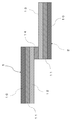
- the surface is the sample 1 in which the copper foil 12 is laminated on the PET film 10 via the double-sided tape 11 and the aluminum-deposited surface of the aluminum-deposited film 13 on the PET film 10 via the double-sided tape 11.
- Sample 2 laminated as described above was prepared, and each sample size was cut to a size of 50 mm ⁇ 20 mm.
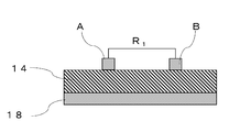
- the conductive adhesive film 14 having a film thickness of 60 ⁇ m made of the conductive adhesive composition obtained above is cut into a size of 20 mm ⁇ 5 mm, laminated on the copper foil 12 of the sample 1, and the temperature is adjusted. After press-pressing at 100 ° C. and a pressure of 0.5 MPa for 30 seconds, the release film 18 was peeled off. Then, as shown in FIG.
- the aluminum-deposited surface of the aluminum-deposited film 13 and the conductive adhesive film 14 were adhered to each other and pressed and crimped for 30 seconds at a temperature of 100 ° C. and a pressure of 0.5 MPa to connect them.
- the aluminum vapor deposition film 13 connected to the sample 3 is peeled off with a tensile tester (PT-200N manufactured by Minebea Co., Ltd.) at a tensile speed of 120 mm / min and a peeling direction of 90 degrees (arrow direction in FIG. 2) until it breaks.
- the average value of the load was used as the measured value. Those having a 90° peel strength of 3.5 N/5 mm or more were considered to have excellent adhesiveness.
- N / 20 mm Similar to the 85 ° C creep strength, sample 1 and sample 2 are bonded and connected with a conductive adhesive film 14, and in accordance with JIS K6850, tension manufactured by Shimadzu Corporation. Using the test "AGS-X50S", a tensile test was performed at a tensile speed of 200 mm / min, and the maximum load at break was measured. Those having a length of 60 N / 20 mm or more were considered to have excellent adhesiveness.
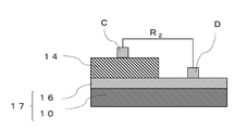
- connection resistivity with the aluminum vapor deposition surface and the connection resistivity with the copper foil surface were measured. Specifically, as shown in FIG. 4, an aluminum vapor deposition film 17 in which an aluminum vapor deposition layer 16 is formed on a PET film 10 is prepared, and a conductive film having a thickness of 60 ⁇ m and made of the conductive adhesive composition obtained above is prepared. The adhesive film 14 was pressed onto the aluminum vapor-deposited film 17 at a temperature of 100 ° C. and a pressure of 0.5 MPa for 30 seconds to transfer the adhesive film 14, and the release film 18 was peeled off.
- the electrode C is placed on the conductive adhesive film 14, and the electrode D is an aluminum vapor deposition film. It was placed on 17.
- the connection resistance value R 2 between the CD electrodes was measured in the same manner as the surface resistivity.
- the connection resistivity with the copper foil surface was measured in the same manner as described above except that the copper foil was used instead of the aluminum vapor deposition film 17 and the electrode D was placed on the copper foil.
- Examples 1 to 7 were excellent in adhesiveness (85 ° C creep strength, 90 ° peel strength, and tensile shear adhesive strength), surface resistivity, and connection resistivity.
- Comparative Example 1 was an example in which a crystalline thermoplastic resin having a melting point of 85 ° C. was used instead of the crystalline thermoplastic resin (A), and the creep strength at 85 ° C. was inferior.
- Comparative Example 2 is an example in which an amorphous thermoplastic resin was used instead of the carboxyl group-modified polyester resin (B), and the 90° peel strength was inferior.
- Comparative Example 3 is an example in which the urethane-modified polyester resin (C) is not contained, and the creep strength at 85 ° C. is inferior.
- Comparative Example 4 is an example in which the content of the conductive filler is less than the lower limit value, and the surface resistivity and the connection resistivity with the aluminum vapor deposition surface were poor.
- Comparative Example 5 is an example in which the content of the conductive filler exceeds the upper limit value, and the creep strength at 85 ° C. and the peel strength at 90 ° C. are inferior.
- Comparative Example 6 is an example in which the shape of the conductive filler is spherical, the electrical connection is anisotropic, and the connection resistivity with the aluminum vapor deposition surface and the connection resistivity with the copper foil surface are inferior. It was
Landscapes
- Chemical & Material Sciences (AREA)
- Organic Chemistry (AREA)
- Inorganic Chemistry (AREA)
- Chemical Kinetics & Catalysis (AREA)
- Adhesives Or Adhesive Processes (AREA)
- Conductive Materials (AREA)
Abstract
Description
・結晶性熱可塑性樹脂2:結晶性ポリエステル、Tm=92℃、Mn=36000
・結晶性熱可塑性樹脂3:結晶性ポリエステル、Tm=85℃、Mn=19000
・非晶性熱可塑性樹脂1:非晶性ポリエステル、Tg=65℃、Mn=16000
・カルボキシル基変性ポリエステル樹脂:Tg=15℃、Mn=16000、酸価=18mgKOH/g
・ウレタン変性ポリエステル樹脂1:Tg=84℃、Mn=40000
・ウレタン変性ポリエステル樹脂2:Tg=106℃、Mn=25000
・導電性フィラー1:デンドライト形状の銀被覆銅粒子、平均粒子径5μm、銀被覆量10質量%
・導電性フィラー2:球状、銀被覆銅粒子、平均粒子径5μm
・ウレタンビーズ:大日精化工業(株)製「ダイナミックビーズ UCN-5050クリヤー」

2・・・・サンプル
3・・・・サンプル
10・・・PETフィルム
11・・・両面テープ
12・・・銅箔
13・・・アルミ蒸着フィルム
14・・・導電性接着フィルム
15・・・ガラスエポキシ基板
16・・・アルミ蒸着層
17・・・アルミ蒸着フィルム
18・・・離型フィルム
A,B,C,D・・・電極
Claims (7)
- 融点が90℃以上の結晶性熱可塑性樹脂(A)と、カルボキシル基変性ポリエステル樹脂(B)、及びウレタン変性ポリエステル樹脂(C)とを少なくとも含有する樹脂成分100質量部に対して、デンドライト形状の導電性フィラーを50~300質量部含有する、導電性接着剤組成物。
- 前記結晶性熱可塑性樹脂(A)が結晶性ポリエステルである、請求項1に記載の導電性接着剤組成物。
- 前記カルボキシル基変性ポリエステル樹脂(B)のガラス転移点が10~30℃である、請求項1又は2に記載の導電性接着剤組成物。
- 前記ウレタン変性ポリエステル樹脂(C)のガラス転移点が80~120℃である、請求項1~3のいずれか1項に記載の導電性接着剤組成物。
- 樹脂成分100質量部中、前記結晶性熱可塑性樹脂(A)の含有量が50~70質量部である、請求項1~4のいずれか1項に記載の導電性接着剤組成物。
- 樹脂成分100質量部中、前記カルボキシル基変性ポリエステル樹脂(B)の含有量が15~35質量部である、請求項1~5のいずれか1項に記載の導電性接着剤組成物。
- 樹脂成分100質量部中、前記ウレタン変性ポリエステル樹脂(C)の含有量が15~35質量部である、請求項1~6のいずれか1項に記載の導電性接着剤組成物。
Priority Applications (3)
| Application Number | Priority Date | Filing Date | Title |
|---|---|---|---|
| KR1020217018539A KR102738134B1 (ko) | 2019-03-04 | 2019-12-12 | 도전성 접착제 조성물 |
| JP2021503413A JP7459048B2 (ja) | 2019-03-04 | 2019-12-12 | 導電性接着剤組成物 |
| CN201980090818.8A CN113330082B (zh) | 2019-03-04 | 2019-12-12 | 导电性胶粘剂组合物 |
Applications Claiming Priority (2)
| Application Number | Priority Date | Filing Date | Title |
|---|---|---|---|
| JP2019038664 | 2019-03-04 | ||
| JP2019-038664 | 2019-03-04 |
Publications (1)
| Publication Number | Publication Date |
|---|---|
| WO2020179179A1 true WO2020179179A1 (ja) | 2020-09-10 |
Family
ID=72338552
Family Applications (1)
| Application Number | Title | Priority Date | Filing Date |
|---|---|---|---|
| PCT/JP2019/048767 Ceased WO2020179179A1 (ja) | 2019-03-04 | 2019-12-12 | 導電性接着剤組成物 |
Country Status (5)
| Country | Link |
|---|---|
| JP (1) | JP7459048B2 (ja) |
| KR (1) | KR102738134B1 (ja) |
| CN (1) | CN113330082B (ja) |
| TW (1) | TWI866934B (ja) |
| WO (1) | WO2020179179A1 (ja) |
Citations (7)
| Publication number | Priority date | Publication date | Assignee | Title |
|---|---|---|---|---|
| JPS6329314B2 (ja) * | 1980-10-13 | 1988-06-13 | Fuji Electric Co Ltd | |
| JP2007242397A (ja) * | 2006-03-08 | 2007-09-20 | Toyobo Co Ltd | 導電性ペースト及びこれを用いた印刷回路、面状発熱体 |
| JP2008147113A (ja) * | 2006-12-13 | 2008-06-26 | Matsushita Electric Ind Co Ltd | 発熱体 |
| JP2017117627A (ja) * | 2015-12-24 | 2017-06-29 | 住友電気工業株式会社 | 絶縁シート及びフラットケーブル |
| WO2017195400A1 (ja) * | 2016-05-12 | 2017-11-16 | 日本メクトロン株式会社 | 導電性接着剤およびシールドフィルム |
| WO2017204218A1 (ja) * | 2016-05-23 | 2017-11-30 | タツタ電線株式会社 | 導電性接着剤組成物 |
| WO2019151188A1 (ja) * | 2018-01-30 | 2019-08-08 | タツタ電線株式会社 | 導電性接着剤組成物 |
Family Cites Families (6)
| Publication number | Priority date | Publication date | Assignee | Title |
|---|---|---|---|---|
| EP1277807B1 (en) | 2001-07-18 | 2007-05-02 | Mitsubishi Engineering-Plastics Corporation | Thermoplastic resin composition |
| WO2009038190A1 (ja) | 2007-09-19 | 2009-03-26 | Hitachi Chemical Company, Ltd. | 接着剤組成物及び接合体 |
| JP5964187B2 (ja) | 2012-09-18 | 2016-08-03 | デクセリアルズ株式会社 | 異方性導電フィルム、接続方法、及び接合体 |
| JP2014102943A (ja) | 2012-11-19 | 2014-06-05 | Dexerials Corp | 異方性導電フィルム、接続方法、及び接合体 |
| EP3004098B1 (en) | 2013-06-06 | 2017-08-09 | Chiesi Farmaceutici S.p.A. | Kinase inhibitors |
| JP6329314B1 (ja) * | 2017-09-28 | 2018-05-23 | タツタ電線株式会社 | 導電性接着剤シート |
-
2019
- 2019-10-29 TW TW108139066A patent/TWI866934B/zh active
- 2019-12-12 WO PCT/JP2019/048767 patent/WO2020179179A1/ja not_active Ceased
- 2019-12-12 KR KR1020217018539A patent/KR102738134B1/ko active Active
- 2019-12-12 JP JP2021503413A patent/JP7459048B2/ja active Active
- 2019-12-12 CN CN201980090818.8A patent/CN113330082B/zh active Active
Patent Citations (7)
| Publication number | Priority date | Publication date | Assignee | Title |
|---|---|---|---|---|
| JPS6329314B2 (ja) * | 1980-10-13 | 1988-06-13 | Fuji Electric Co Ltd | |
| JP2007242397A (ja) * | 2006-03-08 | 2007-09-20 | Toyobo Co Ltd | 導電性ペースト及びこれを用いた印刷回路、面状発熱体 |
| JP2008147113A (ja) * | 2006-12-13 | 2008-06-26 | Matsushita Electric Ind Co Ltd | 発熱体 |
| JP2017117627A (ja) * | 2015-12-24 | 2017-06-29 | 住友電気工業株式会社 | 絶縁シート及びフラットケーブル |
| WO2017195400A1 (ja) * | 2016-05-12 | 2017-11-16 | 日本メクトロン株式会社 | 導電性接着剤およびシールドフィルム |
| WO2017204218A1 (ja) * | 2016-05-23 | 2017-11-30 | タツタ電線株式会社 | 導電性接着剤組成物 |
| WO2019151188A1 (ja) * | 2018-01-30 | 2019-08-08 | タツタ電線株式会社 | 導電性接着剤組成物 |
Also Published As
| Publication number | Publication date |
|---|---|
| KR20210133949A (ko) | 2021-11-08 |
| CN113330082A (zh) | 2021-08-31 |
| JPWO2020179179A1 (ja) | 2020-09-10 |
| KR102738134B1 (ko) | 2024-12-03 |
| TWI866934B (zh) | 2024-12-21 |
| TW202043407A (zh) | 2020-12-01 |
| JP7459048B2 (ja) | 2024-04-01 |
| CN113330082B (zh) | 2023-04-28 |
Similar Documents
| Publication | Publication Date | Title |
|---|---|---|
| JP3475959B2 (ja) | 接着剤組成物、該接着剤組成物を用いたフィルム状接着剤の製造方法、並びに該接着剤を用いた電極の接続体、及び接着剤付金属箔 | |
| CN102533197A (zh) | 粘合剂组合物、采用它的粘合膜及布线膜 | |
| JP7225505B2 (ja) | 導電性接着剤組成物 | |
| JP4572562B2 (ja) | フィルム状接着剤 | |
| JP6408759B2 (ja) | 接着剤組成物、及びフィルム巻装体 | |
| JP6805190B2 (ja) | 導電性接着剤組成物 | |
| JP3947532B2 (ja) | 異方導電性接着剤フィルム | |
| JP5675975B2 (ja) | 接着剤組成物及び接着フィルム | |
| WO2020179179A1 (ja) | 導電性接着剤組成物 | |
| JP2008308682A (ja) | 回路接続材料 | |
| JP2010024384A (ja) | 異方導電性組成物 | |
| JP6301366B2 (ja) | 電子部品接着材料及び電子部品の接着方法 | |
| KR20200107994A (ko) | 실장체 | |
| JP3480754B2 (ja) | 異方導電フィルムの製造方法 | |
| JP4730215B2 (ja) | 異方導電性接着剤フィルム | |
| JP5365816B2 (ja) | 絶縁被覆導電粒子 | |
| CN107848283B (zh) | 各向异性导电膜以及使用其的显示装置 | |
| WO2024116988A1 (ja) | 異方性導電フィルム、接続構造体および接続構造体の製造方法 | |
| HK1198448A1 (en) | Anisotropic conductive film, connecting method and joined structure | |
| HK1198448B (en) | Anisotropic conductive film, connecting method and joined structure |
Legal Events
| Date | Code | Title | Description |
|---|---|---|---|
| 121 | Ep: the epo has been informed by wipo that ep was designated in this application |
Ref document number: 19918217 Country of ref document: EP Kind code of ref document: A1 |
|
| ENP | Entry into the national phase |
Ref document number: 2021503413 Country of ref document: JP Kind code of ref document: A |
|
| ENP | Entry into the national phase |
Ref document number: 20217018539 Country of ref document: KR Kind code of ref document: A |
|
| NENP | Non-entry into the national phase |
Ref country code: DE |
|
| 122 | Ep: pct application non-entry in european phase |
Ref document number: 19918217 Country of ref document: EP Kind code of ref document: A1 |