WO2020178992A1 - 介助システム - Google Patents
介助システム Download PDFInfo
- Publication number
- WO2020178992A1 WO2020178992A1 PCT/JP2019/008718 JP2019008718W WO2020178992A1 WO 2020178992 A1 WO2020178992 A1 WO 2020178992A1 JP 2019008718 W JP2019008718 W JP 2019008718W WO 2020178992 A1 WO2020178992 A1 WO 2020178992A1
- Authority
- WO
- WIPO (PCT)
- Prior art keywords
- information
- assistance
- user
- usage
- assistance device
- Prior art date
Links
Images


Classifications
-
- A—HUMAN NECESSITIES
- A61—MEDICAL OR VETERINARY SCIENCE; HYGIENE
- A61G—TRANSPORT, PERSONAL CONVEYANCES, OR ACCOMMODATION SPECIALLY ADAPTED FOR PATIENTS OR DISABLED PERSONS; OPERATING TABLES OR CHAIRS; CHAIRS FOR DENTISTRY; FUNERAL DEVICES
- A61G7/00—Beds specially adapted for nursing; Devices for lifting patients or disabled persons
- A61G7/10—Devices for lifting patients or disabled persons, e.g. special adaptations of hoists thereto
- A61G7/1013—Lifting of patients by
- A61G7/1017—Pivoting arms, e.g. crane type mechanisms
-
- G—PHYSICS
- G16—INFORMATION AND COMMUNICATION TECHNOLOGY [ICT] SPECIALLY ADAPTED FOR SPECIFIC APPLICATION FIELDS
- G16H—HEALTHCARE INFORMATICS, i.e. INFORMATION AND COMMUNICATION TECHNOLOGY [ICT] SPECIALLY ADAPTED FOR THE HANDLING OR PROCESSING OF MEDICAL OR HEALTHCARE DATA
- G16H20/00—ICT specially adapted for therapies or health-improving plans, e.g. for handling prescriptions, for steering therapy or for monitoring patient compliance
-
- A—HUMAN NECESSITIES
- A61—MEDICAL OR VETERINARY SCIENCE; HYGIENE
- A61G—TRANSPORT, PERSONAL CONVEYANCES, OR ACCOMMODATION SPECIALLY ADAPTED FOR PATIENTS OR DISABLED PERSONS; OPERATING TABLES OR CHAIRS; CHAIRS FOR DENTISTRY; FUNERAL DEVICES
- A61G5/00—Chairs or personal conveyances specially adapted for patients or disabled persons, e.g. wheelchairs
- A61G5/10—Parts, details or accessories
- A61G5/12—Rests specially adapted therefor, e.g. for the head or the feet
-
- A—HUMAN NECESSITIES
- A61—MEDICAL OR VETERINARY SCIENCE; HYGIENE
- A61G—TRANSPORT, PERSONAL CONVEYANCES, OR ACCOMMODATION SPECIALLY ADAPTED FOR PATIENTS OR DISABLED PERSONS; OPERATING TABLES OR CHAIRS; CHAIRS FOR DENTISTRY; FUNERAL DEVICES
- A61G5/00—Chairs or personal conveyances specially adapted for patients or disabled persons, e.g. wheelchairs
- A61G5/10—Parts, details or accessories
- A61G5/14—Standing-up or sitting-down aids
-
- A—HUMAN NECESSITIES
- A61—MEDICAL OR VETERINARY SCIENCE; HYGIENE
- A61G—TRANSPORT, PERSONAL CONVEYANCES, OR ACCOMMODATION SPECIALLY ADAPTED FOR PATIENTS OR DISABLED PERSONS; OPERATING TABLES OR CHAIRS; CHAIRS FOR DENTISTRY; FUNERAL DEVICES
- A61G7/00—Beds specially adapted for nursing; Devices for lifting patients or disabled persons
- A61G7/10—Devices for lifting patients or disabled persons, e.g. special adaptations of hoists thereto
- A61G7/1001—Devices for lifting patients or disabled persons, e.g. special adaptations of hoists thereto specially adapted for specific applications
- A61G7/1007—Devices for lifting patients or disabled persons, e.g. special adaptations of hoists thereto specially adapted for specific applications mounted on or in combination with a toilet
-
- A—HUMAN NECESSITIES
- A61—MEDICAL OR VETERINARY SCIENCE; HYGIENE
- A61G—TRANSPORT, PERSONAL CONVEYANCES, OR ACCOMMODATION SPECIALLY ADAPTED FOR PATIENTS OR DISABLED PERSONS; OPERATING TABLES OR CHAIRS; CHAIRS FOR DENTISTRY; FUNERAL DEVICES
- A61G7/00—Beds specially adapted for nursing; Devices for lifting patients or disabled persons
- A61G7/10—Devices for lifting patients or disabled persons, e.g. special adaptations of hoists thereto
- A61G7/1013—Lifting of patients by
- A61G7/1019—Vertical extending columns or mechanisms
-
- A—HUMAN NECESSITIES
- A61—MEDICAL OR VETERINARY SCIENCE; HYGIENE
- A61G—TRANSPORT, PERSONAL CONVEYANCES, OR ACCOMMODATION SPECIALLY ADAPTED FOR PATIENTS OR DISABLED PERSONS; OPERATING TABLES OR CHAIRS; CHAIRS FOR DENTISTRY; FUNERAL DEVICES
- A61G7/00—Beds specially adapted for nursing; Devices for lifting patients or disabled persons
- A61G7/10—Devices for lifting patients or disabled persons, e.g. special adaptations of hoists thereto
- A61G7/104—Devices carried or supported by
- A61G7/1046—Mobile bases, e.g. having wheels
-
- A—HUMAN NECESSITIES
- A61—MEDICAL OR VETERINARY SCIENCE; HYGIENE
- A61G—TRANSPORT, PERSONAL CONVEYANCES, OR ACCOMMODATION SPECIALLY ADAPTED FOR PATIENTS OR DISABLED PERSONS; OPERATING TABLES OR CHAIRS; CHAIRS FOR DENTISTRY; FUNERAL DEVICES
- A61G7/00—Beds specially adapted for nursing; Devices for lifting patients or disabled persons
- A61G7/10—Devices for lifting patients or disabled persons, e.g. special adaptations of hoists thereto
- A61G7/1063—Safety means
- A61G7/1065—Safety means with electronic monitoring
-
- A—HUMAN NECESSITIES
- A61—MEDICAL OR VETERINARY SCIENCE; HYGIENE
- A61G—TRANSPORT, PERSONAL CONVEYANCES, OR ACCOMMODATION SPECIALLY ADAPTED FOR PATIENTS OR DISABLED PERSONS; OPERATING TABLES OR CHAIRS; CHAIRS FOR DENTISTRY; FUNERAL DEVICES
- A61G7/00—Beds specially adapted for nursing; Devices for lifting patients or disabled persons
- A61G7/10—Devices for lifting patients or disabled persons, e.g. special adaptations of hoists thereto
- A61G7/1073—Parts, details or accessories
- A61G7/108—Weighing means
-
- G—PHYSICS
- G16—INFORMATION AND COMMUNICATION TECHNOLOGY [ICT] SPECIALLY ADAPTED FOR SPECIFIC APPLICATION FIELDS
- G16H—HEALTHCARE INFORMATICS, i.e. INFORMATION AND COMMUNICATION TECHNOLOGY [ICT] SPECIALLY ADAPTED FOR THE HANDLING OR PROCESSING OF MEDICAL OR HEALTHCARE DATA
- G16H40/00—ICT specially adapted for the management or administration of healthcare resources or facilities; ICT specially adapted for the management or operation of medical equipment or devices
- G16H40/60—ICT specially adapted for the management or administration of healthcare resources or facilities; ICT specially adapted for the management or operation of medical equipment or devices for the operation of medical equipment or devices
- G16H40/63—ICT specially adapted for the management or administration of healthcare resources or facilities; ICT specially adapted for the management or operation of medical equipment or devices for the operation of medical equipment or devices for local operation
-
- A—HUMAN NECESSITIES
- A61—MEDICAL OR VETERINARY SCIENCE; HYGIENE
- A61G—TRANSPORT, PERSONAL CONVEYANCES, OR ACCOMMODATION SPECIALLY ADAPTED FOR PATIENTS OR DISABLED PERSONS; OPERATING TABLES OR CHAIRS; CHAIRS FOR DENTISTRY; FUNERAL DEVICES
- A61G2200/00—Information related to the kind of patient or his position
- A61G2200/50—Information related to the kind of patient or his position the patient is supported by a specific part of the body
- A61G2200/52—Underarm
-
- A—HUMAN NECESSITIES
- A61—MEDICAL OR VETERINARY SCIENCE; HYGIENE
- A61G—TRANSPORT, PERSONAL CONVEYANCES, OR ACCOMMODATION SPECIALLY ADAPTED FOR PATIENTS OR DISABLED PERSONS; OPERATING TABLES OR CHAIRS; CHAIRS FOR DENTISTRY; FUNERAL DEVICES
- A61G2203/00—General characteristics of devices
- A61G2203/10—General characteristics of devices characterised by specific control means, e.g. for adjustment or steering
- A61G2203/16—Touchpads
-
- A—HUMAN NECESSITIES
- A61—MEDICAL OR VETERINARY SCIENCE; HYGIENE
- A61G—TRANSPORT, PERSONAL CONVEYANCES, OR ACCOMMODATION SPECIALLY ADAPTED FOR PATIENTS OR DISABLED PERSONS; OPERATING TABLES OR CHAIRS; CHAIRS FOR DENTISTRY; FUNERAL DEVICES
- A61G2203/00—General characteristics of devices
- A61G2203/10—General characteristics of devices characterised by specific control means, e.g. for adjustment or steering
- A61G2203/20—Displays or monitors
-
- A—HUMAN NECESSITIES
- A61—MEDICAL OR VETERINARY SCIENCE; HYGIENE
- A61G—TRANSPORT, PERSONAL CONVEYANCES, OR ACCOMMODATION SPECIALLY ADAPTED FOR PATIENTS OR DISABLED PERSONS; OPERATING TABLES OR CHAIRS; CHAIRS FOR DENTISTRY; FUNERAL DEVICES
- A61G2203/00—General characteristics of devices
- A61G2203/30—General characteristics of devices characterised by sensor means
- A61G2203/32—General characteristics of devices characterised by sensor means for force
-
- A—HUMAN NECESSITIES
- A61—MEDICAL OR VETERINARY SCIENCE; HYGIENE
- A61G—TRANSPORT, PERSONAL CONVEYANCES, OR ACCOMMODATION SPECIALLY ADAPTED FOR PATIENTS OR DISABLED PERSONS; OPERATING TABLES OR CHAIRS; CHAIRS FOR DENTISTRY; FUNERAL DEVICES
- A61G2203/00—General characteristics of devices
- A61G2203/30—General characteristics of devices characterised by sensor means
- A61G2203/44—General characteristics of devices characterised by sensor means for weight
-
- A—HUMAN NECESSITIES
- A61—MEDICAL OR VETERINARY SCIENCE; HYGIENE
- A61G—TRANSPORT, PERSONAL CONVEYANCES, OR ACCOMMODATION SPECIALLY ADAPTED FOR PATIENTS OR DISABLED PERSONS; OPERATING TABLES OR CHAIRS; CHAIRS FOR DENTISTRY; FUNERAL DEVICES
- A61G2203/00—General characteristics of devices
- A61G2203/70—General characteristics of devices with special adaptations, e.g. for safety or comfort
Definitions
- the present invention relates to an assistance system.
- Patent Document 1 discloses an assistance device that assists the transfer operation of the person being assisted.
- this assisting device changes the direction after the standing motion of raising the buttocks of the seated person from the seat surface is completed, and lowers the buttocks of the person to be seated. Do. Thereby, the person being assisted is transferred from the bed to the wheelchair, for example.
- the caregiver who assists the person being assisted discovers the physical condition change of the person being assisted who is the assistance device at an early stage.
- the purpose of this specification is to provide a assistance system that can predict changes in the physical condition of a person being assisted by grasping changes in the usage status of the assistance device by the person being assisted.
- the usage information regarding the use of the assistance device that assists the operation of the person being assisted is the time information regarding the date and time when the assistance device is used, and the identification of the user who used the assistance device.
- a storage unit that stores the use record data recorded in association with the user identification information to be used, and based on the user identification information included in the use record data, the use information and the time information regarding the specific user.
- an assistance system that includes an extraction unit that extracts and a display unit that displays a time-series change of the usage information about the specific user in a manner that can be grasped.
- the usage information regarding the use of the assistance device that assists the operation of the person being assisted the time information regarding the date and time when the assistance device is used, and the identification of the user who used the assistance device.
- a storage unit that stores the use record data recorded in association with the user identification information to be used, and based on the user identification information included in the use record data, the use information and the time information regarding the specific user.
- an assistance system including an extraction unit for extracting and a display unit for displaying an analysis result regarding a physical condition change of the user based on a time-series change of the use information regarding the specific user.
- the display unit displays the time-series change of usage information regarding a specific user in a form that can be grasped.
- the caregiver or the like who assists the person being assisted can grasp the change in the usage status of the assistance device by the person being assisted.
- the helper or the like can predict a change in the physical condition of the person being assisted based on a change in the usage status of the assistance apparatus by the person being assisted.
- the display unit displays the analysis result regarding the physical condition change of the specific user based on the time series change of the usage information regarding the specific user.
- the caregiver or the like who assists the person being assisted can grasp the change in the usage status of the caregiver by the person being assisted.
- the caregiver or the like can predict the physical condition change of the person being assisted based on the analysis result regarding the physical condition change of the specific user.
- the assistance system records use information obtained when using the assistance device that assists the operation of the person being assisted, as use record data.
- usage record data user identification information that can identify the user who has used it (that is, the person being assisted) is recorded in association with the usage information. Therefore, the assistance system can extract the usage record data of a specific user.
- usage time information regarding the date and time when the assistance device is used is stored in association with the usage information. Thereby, the assistance system can grasp the time-series change of the usage information regarding a specific user. Then, the assistance system presents a time series change of the usage information or an analysis result regarding a physical condition change of the user predicted based on the time series change of the usage information.
- the caregiver who assists the person being assisted, who is the user is the person being assisted who is the person being assisted, based on the time-series change of the usage information presented by the assistance system or the analysis result of the physical condition change of the user. Can predict the deterioration of the person's physical condition.
- the caregiver and the developer of the caregiver measure the effect of using the caregiver based on the analysis result of the time-series change of the usage information presented by the caregiver system or the physical condition change of the user. It can be performed.
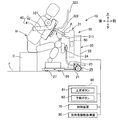
- the assistance system 1 is mainly configured by one or more assistance devices 10, a management server 90, and one or more management devices 100.
- the assistance device 10 is used when assisting the operation of the person being assisted.
- all the assistance devices 10 and the management device 100 are communicatively connected to the management server 90 via the Internet, and the management device 100 integrally manages all the assistance devices 10 provided in the assistance system 1. To do.
- the assistance device 10 assists the standing movement from the sitting posture to the standing posture and the sitting movement from the standing posture to the sitting posture of the user H (see FIG. 2).
- the "standing posture" of the user H means a posture in which the lower body of the user H is standing, regardless of the posture of the upper body. That is, the standing motion of the user H is a motion of raising the buttocks of the user H to the standing posture.
- the sitting motion of the user H is a motion of lowering the buttocks of the user H to the sitting posture.
- the assistance device 10 supports, for example, a part of the body of the user H (for example, the upper half of the body of the user H), assists the standing motion of the user H in the sitting posture, and then changes the direction.
- the transfer operation is assisted to assist the seating operation so that the person is seated again at the position.
- Such a transfer operation is performed for the purpose of, for example, a transfer between a bed and a wheelchair in a living room, a transfer between a bed in a living room and a toilet bowl in a toilet room, and the like.
- the assistance device 10 records various information obtained when assisting the operation of the user H. Then, the assistance device 10 uploads the recorded various information to the management server 90 as the usage record data M1.
- the management server 90 stores the usage record data M1 uploaded from the plurality of assistance devices 10. Then, the management server 90 transmits the usage record data M1 to the management device 100 in response to a request from the management device 100.
- the management server 90 can also transmit only a part of the usage record data M1 in response to the request to the management device 100 among all the stored usage record data M1.
- the management server 90 can also send only the usage record data M1 regarding a specific user H to the management device 100. Further, when the usage record data M1 includes a plurality of types of usage information, the management server 90 can transmit only specific types of usage information to the management device 100. Thereby, the management device 100 can appropriately download only the necessary information from the management server 90.
- the management device 100 targets all the assistance devices 10 provided in the assistance system 1, and acquires the usage record data M1 recorded by each assistance device 10 from the management server 90. Then, the management device 100 provides various information based on the acquired use record data M1. As the management device 100, a terminal device such as a personal computer or a mobile terminal (smartphone, tablet terminal) installed in a facility where the assistance device 10 is installed is exemplified. Further, the management device 100 can add information acquired from the outside of the assistance device 10 to the usage record data M1 acquired from the assistance device 10 via the management server 90.
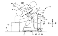
- the assistance device 10 includes a base 20, a drive device 30, a support member 40, a load sensor 50, an operation device 60, a control device 70, and a user information acquisition unit 80. Mainly prepare.
- the base 20 mainly includes a frame 21, a support column 22, a footrest base 23, a lower leg rest 24, and six wheels 25-27.
- the frame 21 is provided substantially horizontally near the floor surface F.
- the column 22 is fixed to the frame 21 in a state of extending upward from the center of the frame 21 in the left-right direction near the front.
- the columns 22 may be provided so as to be vertical to the floor surface F, or may be provided so as to form a predetermined angle in the front-rear direction.
- the footrest 23 is fixed to the rear of the upper surface of the frame 21 so as to be horizontal.
- the lower leg rest 24 is fixed to the column 22 so as to be located above the footrest 23.
- the lower leg support portion 24 has a cushion member at a site where the lower leg of the user H contacts.
- the drive device 30 movably supports the support member 40 that supports the upper body of the user H in the vertical direction and the front-rear direction of the base 20.
- the drive device 30 includes an elevating part 31 and a swinging part 32.
- the drive device 30 is controlled by the control device 70 to operate the elevating part 31 and the swinging part 32.
- the drive device 30 is configured to move the support member 40 along a predetermined movement locus by coordinating the vertical movement of the elevating part 31 and the turning movement of the swinging part 32.
- the elevating part 31 moves linearly in the vertical direction with respect to the base 20.
- the elevating portion 31 is formed in a long shape that is long in the vertical direction, and is guided by a guide (not shown) on the rear surface of the column 22.
- the elevating part 31 is moved up and down along the guide of the support column 22 by driving a linear motion device (not shown).
- a motor (not shown) for turning the swinging part 32 is housed inside the elevating part 31.
- the elevating part 31 has a swing support part 311.
- the swing support portion 311 supports the swing portion 32 rotatably around the central axis A.
- the swinging part 32 swings around the central axis A provided on the elevating part 31 to swing the support member 40.
- the swing unit 32 includes a swing body 321, an arm 322, and a handle 323.
- the swing body 321 is a mounting portion to which the support member 40 is attached and detached, and the arm 322 and the handle 323 are integrally fixed to the swing body 321.
- One end of the arm 322 is rotatably supported around the central axis A of the swing support portion 311 of the elevating portion 31.
- the handle 323 is formed in a substantially quadrangular frame shape.
- the arm 322 is rotated by driving a motor.
- the assistance device 10 assists the standing motion
- the arm 322 mainly turns forward from the state of extending rearward.
- the assistance device 10 assists the sitting motion
- the arm 322 mainly turns backward so that the arm 322 extends rearward.
- the swing portion 32 swivels around a horizontal axis (central axis A) parallel to the left-right direction of the base 20, and is attached to the swing body 321 on the tip end side of the arm 322.
- the member 40 is swung.
- the handle 323 is formed so as to extend forward and upward from the vicinity of the rear end of the arm 322.
- the side portion of the handle 323 is used as a portion gripped by both hands of the user H. Further, the side portion and the front portion of the handle 323 are used as portions that are gripped by the caregiver to move the assistance device 10.
- the support member 40 is a member that supports the upper half of the user H.
- the support member 40 includes a body support portion 41 and a pair of side support portions 42.
- the body support portion 41 is formed in a planar shape close to the body shape of the user H, and can be flexibly deformed.
- the support surface of the body support portion 41 is in surface contact with the front surface of the body of the upper half of the user H to support the body.
- the support surface of the body support portion 41 supports the range from the chest to the abdomen of the user H from below. Further, the body support portion 41 is attached to the swing body 321.
- the pair of armpit support parts 42 are supported by the body support part 41 and support the armpits of the user H. Specifically, the pair of side support parts 42 are swingably supported with respect to the body support part 41 on both left and right sides of the body support part 41.
- the armpit support part 42 is formed in an L shape by a rod-shaped member. The surface of the side support portion 42 is covered with a material that can be flexibly deformed.
- the load sensor 50 is a load cell capable of detecting the load received by the assistance device 10.
- the load sensor 50 is provided on the elevating unit 31. That is, the elevating part 31 is a part that supports the upper half of the body of the user H during the operation of the assistance device 10, and the load sensor 50 is a downward load that the elevating part 31 receives from the user H during the operation of the assistance device 10. To detect. Thereby, the assistance device 10 can grasp the load applied to the assistance device 10 from the upper half of the user H. The detected value detected by the load sensor 50 is output to the control device 70 as the load value received by the assistance device 10.
- the assistance device 10 may include a plurality of load sensors 50.
- the assistance device 10 may be provided with a load sensor 50 for detecting the forward load received from the user H by the elevating unit 31 during the operation of the assisting device 10. Accordingly, the assistance device 10 can grasp the forward load received by the assistance device 10 from the user H.
- the load sensor 50 may be provided on the lower leg support portion 24.
- the assistance device 10 can detect the load applied to the assistance device 10 from the lower leg of the user H. For example, when the assistance device 10 has a configuration in which the lower leg of the user H in the standing posture is supported by the lower leg support portion 24, the assistance device 10 can grasp the forward load received from the user H by the assistance device 10. ..
- the load sensor 50 can be provided on the footrest 23.
- the assistance device 10 can detect the downward load applied to the assistance device 10 from the lower body of the user H.
- the assistance device 10 grasps both the downward load received by the elevating unit 31 and the downward load received by the footrest 23, so that the user H during the operation of the assistance device 10 The ratio of the load applied from the upper half of the body to the load applied from the lower half of the user H can be grasped.
- the operation device 60 has a plurality of buttons corresponding to various operations assisted by the assistance device 10.
- the operating device 60 includes an ascending button 61 corresponding to an ascending operation and a descending button 62 corresponding to a descending operation.
- the operation device 60 is connected to the control device 70 via, for example, a stretchable signal cable. When any button is pressed, the operation device 60 sends a signal corresponding to the type of the button to the control device 70 while the button is pressed.
- the control device 70 controls the operations of the elevating part 31 and the swinging part 32 of the drive device 30.
- the control device 70 operates the elevating unit 31 and the swinging unit 32 based on the operation on the operating device 60 in the operation processing for assisting the standing operation and the sitting operation of the user H.
- the control device 70 controls the movement of the support member 40 by coordinating the vertical movement of the elevating portion 31 and the turning movement of the swinging portion 32 when executing the standing motion and the sitting motion.
- control device 70 records the information acquired during the operation of the assistance device 10. Specifically, the control device 70 records usage time information regarding the date and time when the assistance device 10 is used, and usage information regarding the use of the assistance device 10. Examples of the usage time information include the date and time when a signal from the operation device 60 is received, the date and time when the assisting device 10 in operation has a specific posture set in advance, and the like. Further, as the usage information, load value information regarding the load value detected by the load sensor 50 is exemplified.
- the user information acquisition unit 80 acquires user identification information that can identify the user H who uses the assistance device 10, and sends the acquired user identification information to the control device 70.
- a method of acquiring user identification information by the user information acquisition unit 80 a method using a keyboard, a mouse, a touch panel, a camera, a microphone, or the like is exemplified. Further, the user identification information is exemplified by ID information assigned to each person being assisted who is the user H, voice of the person being assisted, face image and the like.
- the person being assisted who is the user H
- the user information acquisition unit 80 uses the ID information input using an input device such as a keyboard, a mouse, or a touch panel. get.
- the user information acquisition unit 80 displays the person being assisted who is registered in advance as the user H on the touch panel or the like, and uses one user H selected by the assistant or the like from the displayed users H. It is also possible to acquire person identification information.
- the user information acquisition unit 80 performs biometric authentication such as voice authentication based on the voice of the user H acquired using a microphone or face authentication based on the face image of the user H acquired using a camera, It is also possible to acquire the user identification information of the specified user H.
- the caregiver moves the caregiver 10 near the user H (assisted person) in the sitting posture.
- the caregiver operates the caregiver 10 so that the user H in the sitting posture can get in the vehicle.
- the caregiver adjusts the height of the elevating part 31 according to the height of the user H. Then, the user H puts both legs into the lower side of the support member 40.
- the user H places his or her feet on the footrest 23 and brings the lower leg into contact with the lower leg rest 24. Further, the user H places the body on the body support portion 41. At this time, the upper body of the user H is in a slightly forward tilted posture while being supported by the support member 40. At the same time, the user H inserts the armpit support 42 into the armpit. In this way, the assistance device 10 is set to the start state of the stand-up assistance operation. Then, the caregiver causes the user H to grip the handle 323. The posture of the user H at this time is the starting posture of the standing up assist operation. Subsequently, the caregiver starts driving the care device 10 based on the standing assist program of the care device 10. As a result, the raising/lowering of the raising/lowering unit 31 and the forward tilting of the swinging unit 32 are performed in cooperation with each other.
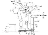
- the assistance device 10 is in the stand-up preparation state shown in FIG.
- the standing up state of the assistance device 10 is a state immediately before the user H in the sitting posture is lifted from the chair C. That is, the assisting device 10 is in the upright preparation state shown in FIG. 3 when the elevating portion 31 descends and the swinging portion 32 tilts forward from the start state shown in FIG.
- the assistance device 10 is in the standing-up preparation state
- the user H is in a state in which the torso is tilted forward and extended with the buttocks in contact with the seating surface of the chair C.
- the posture of the user H at this time is the standing preparation posture.
- the elevating portion 31 rises and the swinging portion 32 further tilts forward.
- the user H changes from the standing preparation posture to the standing posture. That is, the upper body of the user H in the standing posture is in a greatly tilted forward posture, and the position of the buttocks of the user H is located higher than the seating surface of the chair C. Then, the legs of the user H are in a substantially extended state.
- the torso support portion 41 tilts forward while the user H is on the assistance device 10, so that the user H shifts from the starting posture in the sitting posture to the standing posture through the standing preparation posture.
- the sitting assistance operation of the assistance device 10 is substantially the reverse of the standing assistance operation. That is, the user H can be moved from the standing posture to the sitting posture by lowering the elevating portion 31 while the body support portion 41 tilts rearward. Then, the user H in the sitting posture can easily pull out the armpit support part 42 from the armpit.
- the standing posture is a posture in which the load on the lower half of the user H is large. Therefore, if the load that the assisting device 10 receives from the upper body of the user H in the standing posture tends to increase, there is concern that the physical condition of the user H, such as a decrease in leg strength, may occur. To. That is, the caregiver or the like can predict a change in the physical condition of the person being assisted, which is the user H, by grasping the fluctuation of the load that the caregiver 10 receives from the upper half of the body of the user H.
- the assistance device 10 also uploads the usage information and usage time information recorded by the control device 70 and the user identification information acquired by the user information acquisition unit 80 to the management server 90 as usage record data M1. At this time, the usage information is recorded in the usage record data M1 in association with the user identification information and the usage time information.
- the management device 100 mainly includes a storage unit 101, an input unit 102, an extraction unit 103, a display unit 104, a display data generation unit 105, and an analysis unit 106.
- the storage unit 101 is configured by an optical drive device such as a hard disk device or a flash memory.
- the storage unit 101 stores the usage record data M1 acquired from the assistance device 10 via the management server 90. Further, in the usage record data M1, usage information acquired from the outside of the assistance device 10 and capable of grasping the usage of the assistance device 10 is stored as one of the usage information.
- the storage unit 101 stores assistance record data M2 regarding assistance records performed on the person being assisted, which is the user H.
- assistance record data M2 assistance record information regarding assistance performed without using the assistance device 10
- assistance time information regarding the date and time when the assistance was performed
- a person being assisted regarding a person who was assisted It is recorded in association with the identification information.
- the assistance recipient identification information is, for example, the name of the assistance recipient, ID information assigned to each assistance recipient, or the like.
- the storage unit 101 stores the assistance recipient data M3 used for associating the assistance recipient identification information of the assistance recipient registered as the user H of the assistance device 10 with the user identification information.
- the input unit 102 receives an input to an input device (not shown) that can be operated by a helper or the like who uses the assistance system 1.
- the input device provided in the management device 100 is, for example, a keyboard, a mouse, a touch panel, or the like.
- the assistant or the like inputs the person to be assisted identification information of the person to be assisted.
- the input device can also be used when registering a person to be assisted who is a new user of the assistance apparatus 10 in the assistance person data M3, or when adding a new assistance record to the assistance record data M2. Is.
- the extraction unit 103 extracts the user identification information associated with the person being assisted person identification information. Then, the extraction unit 103 extracts the usage information and the usage time information associated with the user identification information from the usage record data M1, and the assistance record information and the assistance time information associated with the care recipient identification information. Is extracted from the assistance record data M2.
- the display unit 104 is a display device 104a (see FIG. 9) that is information about the specific person being assisted extracted by the extracting unit 103, and is used information when the person being assisted uses the assistance apparatus 10 as the user H. To display. At this time, the display unit 104 displays the time-series change of the usage information about the user H in a manner that can be grasped.
- the display data generation unit 105 generates display data to be displayed by the display unit 104 as data indicating time-series changes in usage information. Then, the caregiver or the like can use the display data as data indicating a sign of a change in the physical condition of the specific user H.
- the display data will be described later with specific examples.
- the analysis unit 106 analyzes the physical condition change of the user H based on the time-series change of the usage information regarding the specific user H extracted by the extraction unit 103. Then, the display unit 104 displays the analysis result of the analysis unit 106 on the display device 104a (see FIG. 9).
- the usage record data M1 shown in FIG. 6 includes usage time information, user identification information, and usage information. Then, in the use record data M1, the use information is recorded in association with the use time information and the user identification information.
- the usage time information is usage date/time information related to the date/time when the user information acquisition unit 80 acquired the user identification information.
- the use record data M1 includes, as the use time information, the date and time when the operation device 60 is operated, and the assistance device 10 has a predetermined posture (for example, the posture of the assistance device 10 when the user H is in the standing posture). It is also possible to record the date and time when it becomes). Further, the assistance device 10 acquires use time information at a plurality of different timings during a series of operations of the assistance device 10, and the use record data M1 is a plurality of use times obtained during the series of operations of the assistance device 10. It is also possible to record the use period information calculated based on the information as one of the use time information. Note that examples of the use period information include a standing posture continuation time, a time required to transition from the standing preparation state to the standing completion state, and the like.
- the user identification information is information associated with the assistance recipient identification information.
- the ID information assigned to each of the person being assisted as the user H is recorded as the user identification information.
- the usage information is information obtained when the assistance device 10 is operated.
- the usage record data M1 includes, as usage information, load value information regarding a load value received by the assistance device 10 when the assistance device 10 is used, and an application of the assistance device 10 acquired from outside the assistance device 10. Including information and.
- the load value information is the load value detected by the load sensor 50 during the operation of the assistance device 10.
- a plurality of load value information is recorded in the usage record data M1.
- the plurality of load value information is information regarding the load value detected by the load sensor 50 at different timings during a series of operations of the assistance device 10.
- load value information received when the assisting device 10 in operation takes a specific posture, and a predetermined time from the transition from the standing preparation state to the standing completion state Examples include load value information detected for each elapse, load value acquired for each predetermined time after the standing up is completed, and the like.
- the usage record data M1 can record the maximum value or the average value of the load values detected by the load sensor 50 during a series of operations as the load value information.
- the usage record data M1 can also record load fluctuation information regarding fluctuations in the load value received by the assistance device 10 during the operation of the assistance device 10.
- the usage record data M1 may record the variation of the load value detected by the load sensor 50 as the load variation information over a plurality of times during a series of operations of the assistance device 10 or continuously for a certain period. It is possible.
- the usage information is used by the user H to understand the usage of the assistance device 10.
- the use information is action record information relating to an action performed by the user H while using the assistance device.
- the caregiver or the like can grasp the purpose in which the care recipient, who is the user H, uses the care device 10.
- the action type code assigned according to the action content is recorded as action record information.
- the action record information is information that cannot be acquired from the assistance device 10, and is recorded in the management device 100 by an assistant or the like.
- the usage record data M1 can also include usage position information regarding the position where the assistance device 10 is used as usage information.
- the assistance system 1 can mount a GPS transmitter on the assistance device 10 and acquire information transmitted from the GPS transmitter when the assistance device 10 is operating as usage position information. In this case, since the assistance system 1 can acquire the usage information from the assistance device 10, it is possible to omit the work of recording the usage information by the caregiver or the like.
- Assistance Recording Data M2 Next, a specific example of the assistance recording data M2 will be described with reference to FIG. In the assistance record data M2 shown in FIG. 7, assistance record information for each person being assisted identification information is recorded in association with assistance time information.
- the assistance recipient identification information is information associated with the user identification information as described above.
- the ID information (H11, H12, ...) Assigned to each of the assisted persons who are the users H is recorded as the assisted person identification information.
- the time information is assistance date and time information regarding the date and time when the person being assisted is assisted.
- the assistance record information is recording information relating to assistance without using the assistance apparatus 10, and is recording information that cannot be acquired from the assistance apparatus 10.
- the assigned assistance type code is recorded. Examples of the assistance content recorded as the assistance record information include changing diapers and administration of laxatives.
- the person-to-be-assisted person data M3 stores the person-to-be-assisted person identification information regarding the person-to-be-assisted who is registered in advance as the user H of the assistance apparatus 10 in association with the user-identification information. That is, the user identification information included in the usage record data M1 and the assistance recipient identification information included in the assistance record data M2 are linked via the assistance recipient data M3.
- the person being assisted identification information may be the same as the user identification information.
- the extraction unit 103 collates the extracted user identification information with the usage record data M1. Then, the extraction unit 103 extracts the usage information and the usage time information associated with the extracted user identification information. Similarly, the extraction unit 103 collates the assistance recipient identification information with the assistance record data M2, and extracts assistance assistance record information and assistance time information associated with the corresponding assistance recipient identification information. In this way, the extraction unit 103 extracts information about the person being assisted registered as the user H from the usage record data M1 and the assistance record data M2 stored in the storage unit 101.
- the display data generation unit 105 generates display data by processing the various types of information extracted by the extraction unit 103 in such a manner that the time series change of the usage information can be grasped.
- 9 to 13 show examples of display data displayed on the display device 104a by the display unit 104.
- FIG. 9 shows a graph showing the transition of the usage count information regarding the usage count of the assistance device 10 per predetermined unit period as the display data 105a showing the time-series change of the usage information.
- the display data generation unit 105 calculates the number of times of use of the assistance device 10 for each predetermined period based on the date information included in the time information, and displays the display data 105a based on the calculation result.
- the extraction unit 103 extracts, from the usage record data M1, usage information and time information for four weeks regarding a specific user H. Then, the display data generation unit 105 calculates the number of times the assistance device 10 is used every week in the four weeks, and generates the display data 105a illustrated in FIG.
- the caregiver or the like can predict a change in the physical condition of the person being assisted, who is the user H, by referring to the graph showing the transition of the number of times of use information of the care device 10. That is, regarding the display data 105a, when the number of times of use of the assistance device 10 has increased or decreased for a specific user H, the caregiver or the like notices that the physical condition of the user H is in a recovery tendency or a deterioration tendency. You can give a chance.
- FIG. 10 shows a graph showing the transition of specific load value information as the display data 105b showing the time-series change of the usage information.
- the extraction unit 103 extracts the usage time information and the specific load value information regarding the specific user H from the usage record data M1.
- the display data generation unit 105 generates the display data 105b illustrated in FIG. 10 as a display graph showing the transition of the specific load value information based on the usage time information and the specific load value information.
- the specific load value information is, for example, a load value detected by the load sensor 50 at a specific timing
- the assistance device 10 in operation has a specific posture (for example, the assistance in which the user H is in a standing posture).
- An example is a load value or the like when the device 10 is in a posture or the like.
- the caregiver or the like can predict a change in the physical condition of the person being assisted, who is the user H, by referring to the graph showing the transition of the specific load value information.
- the display data 105b is an opportunity for the caregiver or the like to notice that the physical condition of the user H tends to recover or deteriorate when the specific load value information increases or decreases for the specific user H. Can be given.
- the specific load value information tends to increase
- the caregiver or the like can notice that the muscle strength of the lower half of the person being assisted, which is the user H, may be reduced.
- the caregiver or the like can notice that the muscle strength of the lower half of the person being assisted who is the user H may tend to recover.
- the display unit 104 displays both the display data 105a showing the transition of the number-of-use information shown in FIG. 9 and the display data 105b showing the transition of the load value information shown in FIG. 10 to the display device 104a. It is also possible to display them at the same time. At this time, the display unit 104 displays the display data 105a indicating the transition of the number-of-uses information and the display data 105b indicating the transition of the load value information on the display device 104a in the same unit of the horizontal axis (time axis). Can be displayed. As a result, the caregiver or the like can easily grasp, for example, whether or not the increase / decrease in the number of times of use information and the increase / decrease in the load value information are linked.
- the caregiver or the like is the person being assisted who is the user H. It can be noticed that the physical condition of the person is likely to deteriorate. Similarly, for a specific user H, if the load value tends to increase and the number of times of use tends to increase, the caregiver or the like tends to recover the physical condition of the person being assisted who is the user H. You can notice that it is likely.
- the display unit 104 can simultaneously display a plurality of graphs generated by the display data generation unit 105 on the display device 104a side by side. Then, the management device 100 displays a plurality of types of information regarding the usage status of a specific user H side by side on the display device 104a at the same time, so that an assistant or the like can promptly notice the physical condition change of the user H. Can be given.
- FIG. 11 shows an example of a graph showing the transition of the load variation information of the assistance device 10 as the display data 105c showing the time-series change of the usage information.
- the extraction unit 103 extracts, from the usage record data M1, a plurality of pieces of load value information when the specific user H uses the assistance device 10 at specific timing.
- the extraction unit 103 uses, for example, the assistance device 10 at a determined timing on a determined date within a predetermined period (for example, the first Monday of every month, the 10th of every month, etc.) (for example, the determined time).
- a plurality of pieces of load value information (when the assisting device 10 is first used on a different date) are extracted.
- the display data generation unit 105 creates display data 105c composed of a plurality of graphs showing changes in load fluctuation information as illustrated in FIG. 11 based on the extracted usage time information and load value information. To generate.
- the extraction unit 103 extracts the load value information six times detected by the load sensor 50 at different timings during the series of operations of the assistance device 10. Then, the display data generating unit 105 generates a graph in which the extracted load value information for six times is arranged in time series in the horizontal axis direction for each of the extracted usage time information.
- the load value number 1 is the load value information detected by the load sensor 50 immediately after starting the transition from the standing-up preparation state to the standing state
- the load value number 6 is the standing-up completed state. Is the load value detected by the load sensor 50.
- the display data 105c displays a plurality of graphs generated for each time information in an overlapping manner. This allows the caregiver or the like to easily grasp the transition of the load variation information over time.
- Assistance person, etc. can predict the physical condition change of the person being assisted who is the specific user H by referring to the transition of the load variation information. That is, the display data 105c indicates that when the load variation information of the specific user H varies, the caregiver who is the specific user H is in a recovery tendency or a deterioration tendency of the caregiver. Etc. can give a chance to notice. For example, when there is a tendency that the timing of the increase in the load value tends to be earlier with the passage of time, the caregiver or the like may have decreased muscle strength of the lower half of the person being assisted who is the user H. You can notice that. Further, when there is a tendency that the timing of the increase of the load value is delayed with the passage of time, the caregiver or the like may have recovered the muscle strength of the lower half of the person being assisted who is the user H. You can notice that.
- FIG. 12 shows an example of a graph that collectively shows changes in the number of times the assistance device 10 is used and changes in the number of action records for each action content, as the display data 105d indicating the time-series changes in the usage information. ing.
- the extraction unit 103 extracts the usage time information regarding the specific user H from the usage record data M1.
- the display data generation unit 105 calculates the number of times of use of the assistance device 10 for each predetermined period based on the date information included in the extracted use time information, and displays the transition of the use number information of the assistance device 10. Data 105d for use is generated.
- the extraction unit 103 calculates the assistance time from the assistance record data M2 of the specific user H (assistant) based on the assistance recipient identification information associated with the user identification information of the specific user H. Extract information and assistance record information.
- the assistance record information extracted from the assistance record data M2 and the usage information extracted from the use record data M1 have the same use time information or date information included in the assistance time information.
- the display data generation unit 105 calculates the number of times of assistance recording for each assistance content for each predetermined period based on the date information and the assistance record information included in the extracted assistance time information, and the assistance record for each assistance content. Generate a graph showing the transition of the number of times information.
- the display data generation unit 105 superimposes the graph showing the transition of the number-of-uses information of the assistance device 10 and the graph showing the transition of the assistance-recording number information for each assistance content, and the display data exemplified in FIG. Generate data 105d.
- the display unit 104 displays the time-series change of the assistance record information in a manner that can be compared with the time-series change of the usage information.
- the assistant or the like can easily compare the number of times of use of the assistance device 10 and the number of actions for each action content by referring to the display data 105d illustrated in FIG. For example, when the number of times of use of the assistance device 10 has increased or decreased with respect to a specific user H, the caregiver or the like refers to the increase or decrease in the number of times of activity for each activity content, and estimates the factor that the number of times of use has increased or decreased. be able to.
- the caregiver or the like can measure the effect of the help recipient using the caregiver 10 based on the number of times the caregiver 10 is used and the number of times the activity is classified by activity. For example, when a plurality of users H tend to be associated with an increase/decrease in the number of times the assistance device 10 is used and an increase/decrease in specific action content, the assistance person or the like uses the assistance device 10 as a person being assisted. It is possible to understand the effect on the physical condition of.
- FIG. 13 as the display data 105e showing the time-series change of the usage information, the usage information of the user H of the assistance device 10 and the assistance record information for the person being assisted who is the user H, and the assistance of the user.
- An example of a graph showing the relationship with the time information used by the device 10 is shown.
- the extraction unit 103 extracts usage information on a plurality of predetermined dates within a predetermined period from the usage record data M1.
- the display data generation unit 105 generates a graph in which the extracted usage information is arranged and displayed in chronological order for each extracted date.
- the extraction unit 103 extracts assistance record information on a plurality of predetermined dates within a predetermined period from the assistance record data M2.
- the assistance record information extracted from the assistance record data M2 and the usage information extracted from the use record data M1 have the same use time information or date information included in the assistance time information associated with each other.
- the display data generation unit 105 arranges the extracted assistance record information in time series and adds the assistance record information to the graph showing the usage information to generate display data 105e as shown in FIG.
- the caregiver or the like grasps the use of the caregiver 10 by the specific user H and the number of times of use of the caregiver 10 per day by referring to the display data 105e illustrated in FIG. be able to.
- the caregiver or the like can easily compare the use of the care device 10 and the increase / decrease in the number of times of use with the transition of the care record.
- the caregiver or the like can find a causal relationship between the change in the assistance record, the intended use of the assistance device 10, and the number of times of use when there is a change in the assistance record with respect to a specific person being assisted. .. That is, the caregiver or the like can infer the effect of using the caregiver 10 on the physical condition of the care recipient.
- the analysis unit 106 analyzes a possible physical condition change of the user H based on the transition of the number of times the assistance device 10 is used, the transition of load value information, the transition of load variation information, and the like. Then, the display unit 104 displays the analysis result 106a by the analysis unit 106 on the display device 104a.
- the analysis unit 106 can enumerate, as the analysis result 106a, the items that are assumed to be the cause of the decrease in the number of times of use, based on the transition of the number of times of use information of the assistance device 10 shown in FIG.
- the assistance device 10 should be used as the person being assisted has a decrease in motivation to act due to the decrease in muscle strength of the lower body and the person being assisted has recovered the muscle strength of the lower body. For example, it is possible to act without doing so.
- the management device 100 can notify the caregiver and the like that the user H has a sign of physical condition change by displaying the analysis result 106a by the analysis unit 106. As a result, the caregiver or the like can grasp the change in the physical condition of the user H at an early stage.
- the display unit 104 displays both the display data 105a-105e generated by the display data generation unit 105 and the analysis result 106a by the analysis unit 106 on the display device 104a.
- the explanation has been given as an example, but the present invention is not limited to this. That is, the display unit 104 can display only one of the display data 105a-105e and the analysis result 106a on the display device 104a.
- the analysis unit 106 makes the person being assisted who is the user H sick. It is also possible to inform that there is a risk of being present. For example, the analysis unit 106 can periodically perform analysis and display a list of users H who have no usage history of the assistance device 10 within a certain period of time. In this case, the caregiver or the like can detect a sudden change in the physical condition of the person being assisted at an early stage based on the notification or list display by the analysis unit 106.
- the management device 100 acquires the usage record data M1 recorded by the assistance device 10 via the management server 90.
- the management device 100 may acquire the usage record data M1 by directly communicating with the assistance device 10 via a LAN, for example.
- a part of the configuration of the management device 100 may be the configuration of the assistance device 10 or the management server 90.
- the assistance system 1 may be configured to generate display data in the assistance device 10 or the management server 90 and store the generated display data in the storage unit 101 of the management device 100.
- Assistance system 1: Assistance system
- 10 Assistance device
- 50 Load sensor
- 101 Storage unit
- 103 Extraction unit
- 104 Display unit
- 105a-105e Display data
- 106a Analysis result
- H Assistance device user
- M1 Usage record data
- M2 Assistance record data
Landscapes
- Health & Medical Sciences (AREA)
- Public Health (AREA)
- General Health & Medical Sciences (AREA)
- Veterinary Medicine (AREA)
- Animal Behavior & Ethology (AREA)
- Life Sciences & Earth Sciences (AREA)
- Engineering & Computer Science (AREA)
- Nursing (AREA)
- Biomedical Technology (AREA)
- Primary Health Care (AREA)
- Medical Informatics (AREA)
- Epidemiology (AREA)
- General Business, Economics & Management (AREA)
- Business, Economics & Management (AREA)
- Medical Treatment And Welfare Office Work (AREA)
- Management, Administration, Business Operations System, And Electronic Commerce (AREA)
Priority Applications (7)
| Application Number | Priority Date | Filing Date | Title |
|---|---|---|---|
| CA3131236A CA3131236A1 (en) | 2019-03-05 | 2019-03-05 | Assistance device usage report system |
| PCT/JP2019/008718 WO2020178992A1 (ja) | 2019-03-05 | 2019-03-05 | 介助システム |
| DE112019006985.3T DE112019006985T5 (de) | 2019-03-05 | 2019-03-05 | Assistenzsystem |
| CN201980093370.5A CN113508435A (zh) | 2019-03-05 | 2019-03-05 | 辅助系统 |
| US17/436,068 US20220172832A1 (en) | 2019-03-05 | 2019-03-05 | Assistance system |
| KR1020217008227A KR102588081B1 (ko) | 2019-03-05 | 2019-03-05 | 시중 시스템 |
| JP2021503319A JP7142147B2 (ja) | 2019-03-05 | 2019-03-05 | 介助システム |
Applications Claiming Priority (1)
| Application Number | Priority Date | Filing Date | Title |
|---|---|---|---|
| PCT/JP2019/008718 WO2020178992A1 (ja) | 2019-03-05 | 2019-03-05 | 介助システム |
Publications (1)
| Publication Number | Publication Date |
|---|---|
| WO2020178992A1 true WO2020178992A1 (ja) | 2020-09-10 |
Family
ID=72337724
Family Applications (1)
| Application Number | Title | Priority Date | Filing Date |
|---|---|---|---|
| PCT/JP2019/008718 WO2020178992A1 (ja) | 2019-03-05 | 2019-03-05 | 介助システム |
Country Status (7)
| Country | Link |
|---|---|
| US (1) | US20220172832A1 (ko) |
| JP (1) | JP7142147B2 (ko) |
| KR (1) | KR102588081B1 (ko) |
| CN (1) | CN113508435A (ko) |
| CA (1) | CA3131236A1 (ko) |
| DE (1) | DE112019006985T5 (ko) |
| WO (1) | WO2020178992A1 (ko) |
Citations (4)
| Publication number | Priority date | Publication date | Assignee | Title |
|---|---|---|---|---|
| JP2005332324A (ja) * | 2004-05-21 | 2005-12-02 | Hitachi Software Eng Co Ltd | 介助支援システム |
| JP2006048554A (ja) * | 2004-08-06 | 2006-02-16 | Biophilia Kenkyusho Kk | 遠隔コンピューター在宅健康認識システム |
| US20110301440A1 (en) * | 2010-06-07 | 2011-12-08 | Riley Carl W | Apparatus for supporting and monitoring a person |
| JP2014083365A (ja) * | 2012-10-26 | 2014-05-12 | Japan Health Sciences Foundation | 操作状態計測システム、操作状態計測方法、及びプログラム |
Family Cites Families (11)
| Publication number | Priority date | Publication date | Assignee | Title |
|---|---|---|---|---|
| JP3655608B2 (ja) * | 2002-11-07 | 2005-06-02 | 株式会社コスモ計器 | 体力測定装置 |
| JP2008073501A (ja) | 2006-08-21 | 2008-04-03 | Toshihiko Yasuda | 移乗介助ロボット |
| JP4959260B2 (ja) * | 2006-09-07 | 2012-06-20 | アルケア株式会社 | 下肢訓練装置 |
| JP2009201672A (ja) * | 2008-02-27 | 2009-09-10 | Xing Inc | 運動支援システム、運動支援装置、運動支援方法及びコンピュータプログラム |
| WO2014192085A1 (ja) * | 2013-05-28 | 2014-12-04 | 富士機械製造株式会社 | 介助ロボット |
| US20170024523A1 (en) * | 2015-07-23 | 2017-01-26 | Uptake Technologies, Inc. | Requirement Forecast for Health Care Services |
| JP6674321B2 (ja) * | 2015-08-25 | 2020-04-01 | パナソニック株式会社 | 生活支援システム、方法、及び自動昇降型椅子 |
| JP6573580B2 (ja) * | 2016-06-06 | 2019-09-11 | 株式会社ソフトアップJ | トレーニング支援装置 |
| JP2018023681A (ja) * | 2016-08-12 | 2018-02-15 | セイコーエプソン株式会社 | 情報出力システム、情報出力方法、及び情報出力プログラム |
| US11096848B2 (en) * | 2016-09-12 | 2021-08-24 | Fuji Corporation | Assistance device for identifying a user of the assistance device from a spoken name |
| JP6767566B2 (ja) * | 2017-03-31 | 2020-10-14 | 株式会社Fuji | 介助装置 |
-
2019
- 2019-03-05 DE DE112019006985.3T patent/DE112019006985T5/de active Pending
- 2019-03-05 KR KR1020217008227A patent/KR102588081B1/ko active IP Right Grant
- 2019-03-05 WO PCT/JP2019/008718 patent/WO2020178992A1/ja active Application Filing
- 2019-03-05 JP JP2021503319A patent/JP7142147B2/ja active Active
- 2019-03-05 CN CN201980093370.5A patent/CN113508435A/zh active Pending
- 2019-03-05 US US17/436,068 patent/US20220172832A1/en active Pending
- 2019-03-05 CA CA3131236A patent/CA3131236A1/en active Pending
Patent Citations (4)
| Publication number | Priority date | Publication date | Assignee | Title |
|---|---|---|---|---|
| JP2005332324A (ja) * | 2004-05-21 | 2005-12-02 | Hitachi Software Eng Co Ltd | 介助支援システム |
| JP2006048554A (ja) * | 2004-08-06 | 2006-02-16 | Biophilia Kenkyusho Kk | 遠隔コンピューター在宅健康認識システム |
| US20110301440A1 (en) * | 2010-06-07 | 2011-12-08 | Riley Carl W | Apparatus for supporting and monitoring a person |
| JP2014083365A (ja) * | 2012-10-26 | 2014-05-12 | Japan Health Sciences Foundation | 操作状態計測システム、操作状態計測方法、及びプログラム |
Non-Patent Citations (1)
| Title |
|---|
| URASHIMA, AKIRA ET AL.: "Development of the information collection system from peripheral instruments for in-home patient monitoring system", IPSJ SIG TECHNICAL REPORT, vol. 34, no. 32, 2012, pages 1 - 6 * |
Also Published As
| Publication number | Publication date |
|---|---|
| JPWO2020178992A1 (ja) | 2021-11-18 |
| CN113508435A (zh) | 2021-10-15 |
| KR20210044860A (ko) | 2021-04-23 |
| KR102588081B1 (ko) | 2023-10-11 |
| DE112019006985T5 (de) | 2021-12-16 |
| CA3131236A1 (en) | 2020-09-10 |
| JP7142147B2 (ja) | 2022-09-26 |
| US20220172832A1 (en) | 2022-06-02 |
Similar Documents
| Publication | Publication Date | Title |
|---|---|---|
| JP5206393B2 (ja) | 移乗支援装置、移乗支援装置の制御方法 | |
| CN109689000B (zh) | 介助装置 | |
| JP6712641B2 (ja) | 介助装置 | |
| JP6770831B2 (ja) | マッサージ機を備えた施療システム | |
| CN111714321B (zh) | 一种集成重力测量设备的移动辅助装置和系统 | |
| EP3725279B1 (en) | Patient bed having exercise therapy apparatus | |
| JP2017012426A (ja) | 移乗支援システム | |
| WO2020178992A1 (ja) | 介助システム | |
| JP7105365B2 (ja) | 介助情報管理システム | |
| JPH1099389A (ja) | 歩行訓練機 | |
| WO2019234838A1 (ja) | 介助装置の管理装置および管理方法 | |
| JP5500817B2 (ja) | トレーニング装置 | |
| JP6989701B2 (ja) | 介助装置の管理装置 | |
| JP6974610B2 (ja) | 介助装置の管理装置 | |
| JP6745400B2 (ja) | 介助装置のデータ取得装置 | |
| WO2020021619A1 (ja) | 介助装置の適合判定装置 |
Legal Events
| Date | Code | Title | Description |
|---|---|---|---|
| 121 | Ep: the epo has been informed by wipo that ep was designated in this application |
Ref document number: 19917972 Country of ref document: EP Kind code of ref document: A1 |
|
| ENP | Entry into the national phase |
Ref document number: 20217008227 Country of ref document: KR Kind code of ref document: A |
|
| ENP | Entry into the national phase |
Ref document number: 2021503319 Country of ref document: JP Kind code of ref document: A |
|
| ENP | Entry into the national phase |
Ref document number: 3131236 Country of ref document: CA |
|
| 122 | Ep: pct application non-entry in european phase |
Ref document number: 19917972 Country of ref document: EP Kind code of ref document: A1 |