WO2020174788A1 - 燃料電池セルスタック、燃料電池モジュール、発電システム及び燃料電池セルスタックを作製する方法 - Google Patents
燃料電池セルスタック、燃料電池モジュール、発電システム及び燃料電池セルスタックを作製する方法 Download PDFInfo
- Publication number
- WO2020174788A1 WO2020174788A1 PCT/JP2019/046130 JP2019046130W WO2020174788A1 WO 2020174788 A1 WO2020174788 A1 WO 2020174788A1 JP 2019046130 W JP2019046130 W JP 2019046130W WO 2020174788 A1 WO2020174788 A1 WO 2020174788A1
- Authority
- WO
- WIPO (PCT)
- Prior art keywords
- fuel
- side electrode
- fuel cell
- cell stack
- interconnector
- Prior art date
- Legal status (The legal status is an assumption and is not a legal conclusion. Google has not performed a legal analysis and makes no representation as to the accuracy of the status listed.)
- Ceased
Links
Images




Classifications
-
- H—ELECTRICITY
- H01—ELECTRIC ELEMENTS
- H01M—PROCESSES OR MEANS, e.g. BATTERIES, FOR THE DIRECT CONVERSION OF CHEMICAL ENERGY INTO ELECTRICAL ENERGY
- H01M8/00—Fuel cells; Manufacture thereof
- H01M8/24—Grouping of fuel cells, e.g. stacking of fuel cells
- H01M8/2465—Details of groupings of fuel cells
-
- H—ELECTRICITY
- H01—ELECTRIC ELEMENTS
- H01M—PROCESSES OR MEANS, e.g. BATTERIES, FOR THE DIRECT CONVERSION OF CHEMICAL ENERGY INTO ELECTRICAL ENERGY
- H01M8/00—Fuel cells; Manufacture thereof
- H01M8/02—Details
- H01M8/0202—Collectors; Separators, e.g. bipolar separators; Interconnectors
- H01M8/023—Porous and characterised by the material
- H01M8/0236—Glass; Ceramics; Cermets
-
- H—ELECTRICITY
- H01—ELECTRIC ELEMENTS
- H01M—PROCESSES OR MEANS, e.g. BATTERIES, FOR THE DIRECT CONVERSION OF CHEMICAL ENERGY INTO ELECTRICAL ENERGY
- H01M8/00—Fuel cells; Manufacture thereof
- H01M8/02—Details
- H01M8/0202—Collectors; Separators, e.g. bipolar separators; Interconnectors
- H01M8/0204—Non-porous and characterised by the material
- H01M8/0215—Glass; Ceramic materials
-
- H—ELECTRICITY
- H01—ELECTRIC ELEMENTS
- H01M—PROCESSES OR MEANS, e.g. BATTERIES, FOR THE DIRECT CONVERSION OF CHEMICAL ENERGY INTO ELECTRICAL ENERGY
- H01M8/00—Fuel cells; Manufacture thereof
- H01M8/02—Details
- H01M8/0202—Collectors; Separators, e.g. bipolar separators; Interconnectors
- H01M8/0204—Non-porous and characterised by the material
- H01M8/0223—Composites
- H01M8/0228—Composites in the form of layered or coated products
-
- H—ELECTRICITY
- H01—ELECTRIC ELEMENTS
- H01M—PROCESSES OR MEANS, e.g. BATTERIES, FOR THE DIRECT CONVERSION OF CHEMICAL ENERGY INTO ELECTRICAL ENERGY
- H01M8/00—Fuel cells; Manufacture thereof
- H01M8/02—Details
- H01M8/0202—Collectors; Separators, e.g. bipolar separators; Interconnectors
- H01M8/023—Porous and characterised by the material
- H01M8/0241—Composites
- H01M8/0245—Composites in the form of layered or coated products
-
- H—ELECTRICITY
- H01—ELECTRIC ELEMENTS
- H01M—PROCESSES OR MEANS, e.g. BATTERIES, FOR THE DIRECT CONVERSION OF CHEMICAL ENERGY INTO ELECTRICAL ENERGY
- H01M8/00—Fuel cells; Manufacture thereof
- H01M8/04—Auxiliary arrangements, e.g. for control of pressure or for circulation of fluids
- H01M8/04082—Arrangements for control of reactant parameters, e.g. pressure or concentration
- H01M8/04089—Arrangements for control of reactant parameters, e.g. pressure or concentration of gaseous reactants
- H01M8/04111—Arrangements for control of reactant parameters, e.g. pressure or concentration of gaseous reactants using a compressor turbine assembly
-
- H—ELECTRICITY
- H01—ELECTRIC ELEMENTS
- H01M—PROCESSES OR MEANS, e.g. BATTERIES, FOR THE DIRECT CONVERSION OF CHEMICAL ENERGY INTO ELECTRICAL ENERGY
- H01M8/00—Fuel cells; Manufacture thereof
- H01M8/24—Grouping of fuel cells, e.g. stacking of fuel cells
- H01M8/241—Grouping of fuel cells, e.g. stacking of fuel cells with solid or matrix-supported electrolytes
- H01M8/2425—High-temperature cells with solid electrolytes
- H01M8/2428—Grouping by arranging unit cells on a surface of any form, e.g. planar or tubular
-
- H—ELECTRICITY
- H01—ELECTRIC ELEMENTS
- H01M—PROCESSES OR MEANS, e.g. BATTERIES, FOR THE DIRECT CONVERSION OF CHEMICAL ENERGY INTO ELECTRICAL ENERGY
- H01M8/00—Fuel cells; Manufacture thereof
- H01M8/10—Fuel cells with solid electrolytes
- H01M8/12—Fuel cells with solid electrolytes operating at high temperature, e.g. with stabilised ZrO2 electrolyte
- H01M2008/1293—Fuel cells with solid oxide electrolytes
-
- H—ELECTRICITY
- H01—ELECTRIC ELEMENTS
- H01M—PROCESSES OR MEANS, e.g. BATTERIES, FOR THE DIRECT CONVERSION OF CHEMICAL ENERGY INTO ELECTRICAL ENERGY
- H01M8/00—Fuel cells; Manufacture thereof
- H01M8/24—Grouping of fuel cells, e.g. stacking of fuel cells
- H01M8/241—Grouping of fuel cells, e.g. stacking of fuel cells with solid or matrix-supported electrolytes
- H01M8/2418—Grouping by arranging unit cells in a plane
-
- Y—GENERAL TAGGING OF NEW TECHNOLOGICAL DEVELOPMENTS; GENERAL TAGGING OF CROSS-SECTIONAL TECHNOLOGIES SPANNING OVER SEVERAL SECTIONS OF THE IPC; TECHNICAL SUBJECTS COVERED BY FORMER USPC CROSS-REFERENCE ART COLLECTIONS [XRACs] AND DIGESTS
- Y02—TECHNOLOGIES OR APPLICATIONS FOR MITIGATION OR ADAPTATION AGAINST CLIMATE CHANGE
- Y02E—REDUCTION OF GREENHOUSE GAS [GHG] EMISSIONS, RELATED TO ENERGY GENERATION, TRANSMISSION OR DISTRIBUTION
- Y02E60/00—Enabling technologies; Technologies with a potential or indirect contribution to GHG emissions mitigation
- Y02E60/30—Hydrogen technology
- Y02E60/50—Fuel cells
-
- Y—GENERAL TAGGING OF NEW TECHNOLOGICAL DEVELOPMENTS; GENERAL TAGGING OF CROSS-SECTIONAL TECHNOLOGIES SPANNING OVER SEVERAL SECTIONS OF THE IPC; TECHNICAL SUBJECTS COVERED BY FORMER USPC CROSS-REFERENCE ART COLLECTIONS [XRACs] AND DIGESTS
- Y02—TECHNOLOGIES OR APPLICATIONS FOR MITIGATION OR ADAPTATION AGAINST CLIMATE CHANGE
- Y02P—CLIMATE CHANGE MITIGATION TECHNOLOGIES IN THE PRODUCTION OR PROCESSING OF GOODS
- Y02P70/00—Climate change mitigation technologies in the production process for final industrial or consumer products
- Y02P70/50—Manufacturing or production processes characterised by the final manufactured product
Definitions
- the present disclosure relates to a fuel cell stack, a fuel cell module including the fuel cell stack, a power generation system including the fuel cell module, and a method for manufacturing the fuel cell stack.
- the fuel cell composed of the fuel side electrode, the electrolyte and the oxygen side electrode is used as the minimum unit, and the fuel gas supplied to the fuel side electrode and the oxidizing gas supplied to the oxygen side electrode are chemically reacted.
- a fuel cell that generates electric power by making it a solid oxide fuel cell (SOFC) (Solid Oxide Fuel Cell) uses ceramics such as zirconia ceramics as an electrolyte and operates using city gas, natural gas, petroleum, methanol, coal gasification gas, etc. as fuel.
- SOFC Solid Oxide Fuel Cell
- Such an SOFC is known as a high-efficiency high-temperature fuel cell having a wide operating range and a high operating temperature of about 700 to 1000° C.
- the SOFC is combined with a rotating device such as a gas turbine, a micro gas turbine, and a turbocharger to increase the operating pressure to enable more efficient power generation.
- a rotating device such as a gas turbine, a micro gas turbine, and a turbocharger to increase the operating pressure to enable more efficient power generation.
- the compressed air discharged from the compressor is supplied as an oxidizing gas to the oxygen side electrode of the SOFC, and the high temperature exhaust fuel gas discharged from the SOFC is supplied to a gas turbine or the like.
- Power can be recovered by supplying the combustor at the inlet of the rotating device to burn it and rotating the rotating device with the high-temperature combustion gas generated in the combustor.
- the fuel cell module is configured, for example, to form a cell stack with a plurality of fuel battery cells and to form a power generation chamber with a plurality of cell stacks housed in a container.
- the fuel cell has a fuel gas passage and an oxidizing gas passage therein, supplies fuel gas to the fuel gas passage from a fuel gas supply pipe, and supplies oxidizing gas to the oxidizing gas passage from the oxidizing gas supply pipe. (For example, air) is supplied.
- the cell stack is formed into, for example, a cylindrical shape or a flat plate shape depending on the shape of the base body on which the fuel cells are carried.
- Patent Document 1 discloses a method of manufacturing a cylindrical cell stack in which each material constituting a fuel cell is applied to the surface of a cylindrical substrate tube and fired.
- oxidation resistance resistance
- cost reduction through performance improvement.
- a fuel cell having a solid electrolyte membrane such as SOFC
- the performance can be improved by thinning the solid electrolyte membrane, but since the membrane strength decreases due to thinning, cracks occur due to thermal stress generated by temperature change. Easier to do. If a crack occurs, an oxidizing gas may enter the fuel-side electrode in a high-temperature environment in an emergency when the supply of fuel gas is stopped due to an abnormality or failure, and the fuel-side electrode may be oxidized and damaged in a short time. is there.
- One embodiment according to the present disclosure is to improve the oxidation resistance (robustness) of the fuel cell unit, so that the solid electrolyte membrane that constitutes the fuel cell unit even during an emergency stop in which the supply of fuel gas is interrupted.
- the purpose is to prevent the dense film such as from being damaged in a short time.
- the fuel cell stack is A substrate, A plurality of fuel cells each including a fuel-side electrode, a solid electrolyte membrane, and an oxygen-side electrode laminated on the base; An interconnector film for electrically connecting the fuel side electrode of one of the fuel cells of the adjacent fuel cells of the plurality of fuel cells and the oxygen side electrode of the other fuel cell, A porous material that covers at least the interconnector film in a region between the first fuel-side electrode of one of the fuel cells and the second fuel-side electrode of the other fuel cell of the adjacent fuel cells.
- the solid electrolyte membrane and the interconnector membrane which are dense membranes that do not allow the permeation of oxidizing gas, cover the fuel-side electrodes of the plurality of fuel cells.
- the oxidizing gas on the oxygen side electrode side is prevented from entering the fuel side electrode side.
- the amount of heat change due to the temperature difference between the fuel-side electrodes is large, so that local stress is likely to occur.
- stress concentration is likely to occur at the end portion of the interconnector film due to the difference in coefficient of thermal expansion with other members.
- the porous ceramic film by providing the porous ceramic film so as to cover at least the interconnector film in the region between the fuel-side electrodes of the adjacent fuel cells, the porous ceramic film is solid.
- the oxidation resistance (robustness) of the fuel cell can be improved by relaxing the stress generated in the electrolyte membrane and the interconnector membrane and suppressing the damage of the dense membrane.
- the “oxidizing gas” is a gas containing approximately 15% to 30% of oxygen, and air is typically suitable, but in addition to air, a mixed gas of combustion exhaust gas and air, A mixed gas of oxygen and air can be used.
- the porous ceramic membrane By providing the porous ceramic membrane so as to cover the interconnector membrane, it functions as a strength member of the interconnector membrane, and stress generated in the solid electrolyte membrane or interconnector membrane in the fuel-side electrode area due to the temperature difference of the fuel-side electrode Has a relaxing effect. Further, the porous ceramic membrane has a smaller locally generated stress than the dense membrane, and even if a minute crack occurs in the solid electrolyte membrane or the interconnector membrane, the crack extension can be suppressed.
- the interconnector film extends from the first fuel side electrode toward the second fuel side electrode in a region between the fuel side electrodes and extends to a position before the second fuel side electrode.
- the interconnector film extends in the fuel-side interelectrode region, whereby a two-layer structure of the interconnector film and the porous ceramic film can be formed in the fuel-side interelectrode region. Thereby, the oxidation resistance can be improved in the region between the fuel side electrodes.
- the interconnector film extends from the first fuel side electrode toward the second fuel side electrode in a region between the fuel side electrodes and extends to reach the second fuel side electrode. According to the configuration of the above (3), since the interconnector film extends from the first fuel side electrode to the second fuel side electrode, the entire fuel side interelectrode region should be covered with the two-layer structure. You can Thereby, the oxidation resistance can be improved in the region between the fuel side electrodes.
- the second fuel-side electrode has an inclined portion whose thickness gradually decreases toward the first fuel-side electrode, and the interconnector film extends to an inclined region intermediate portion of the inclined portion.
- the interconnector film extends to the middle of the inclined region of the inclined portion of the second fuel-side electrode, so that oxidation resistance can be improved in the region between the fuel-side electrodes. Further, since the interconnector film does not extend beyond the intermediate portion of the inclined portion, it does not reduce the power generation area formed on the second fuel side electrode side. Therefore, the power generation performance is not deteriorated.
- the interconnector film extends to a region of 30% or more and 70% or less in the inclination direction of the inclined portion. According to the above configuration (5), since the interconnector film extends up to the region of 30 to 70% in the inclination direction of the inclined portion of the second fuel side electrode, the oxidation resistance of the fuel side interelectrode region can be improved. At the same time, it does not reduce the power generation performance.
- the porous ceramic membrane extends from the first fuel side electrode toward the second fuel side electrode in a region between the fuel side electrodes, and extends to the second fuel side electrode,
- the second fuel-side electrode has an inclined portion whose thickness gradually decreases toward the first fuel-side electrode, and the porous ceramic membrane extends to at least a part of the inclined portion.
- the porous ceramic membrane extends from the first fuel-side electrode to at least a partial region of the inclined portion of the second fuel-side electrode. Oxidation resistance can be improved by relaxing the generated stress and suppressing damage to the dense film.
- the porous ceramic membrane does not extend beyond the inclined portion of the second fuel side electrode to the second fuel side electrode side, it does not deteriorate the power generation performance on the second fuel side electrode side.
- the porous ceramic membrane extends to a region of 1/2 or less in the inclination direction of the inclined portion.
- the porous ceramic membrane extends from the first fuel-side electrode to a region of the inclined portion of the second fuel-side electrode that is 1/2 or less in the inclination direction.
- the oxidation resistance of the interstitial region can be improved, and since it does not extend to the second fuel side electrode side beyond the inclination direction 1/2 of the inclined portion, the oxygen side provided outside the second fuel side electrode It does not lead to thinning of the electrode, and therefore does not lead to deterioration of the performance of the oxygen-side electrode.
- the solid electrolyte membrane is provided on the substrate side of the interconnector membrane in the region between the fuel side electrodes, and extends from the second fuel side electrode to the first fuel side electrode.
- the solid electrolyte membrane extends to the fuel-side interelectrode area, so that the solid electrolyte membrane having a large film thickness can be formed in the fuel-side interelectrode area.
- the strength of the solid electrolyte membrane in the region between the fuel-side electrodes can be increased, and the oxidation resistance can be improved.
- the porous ceramic membrane is made of a material having a porosity of 10% or more and 60% or less. According to the configuration of (9) above, since the porous ceramic membrane is made of a material having a porosity of 10% or more, the stress generated in the fuel-side interelectrode region can be relaxed, and when the porosity is 60% or less, oxygen can be reduced. The permeation amount due to gas diffusion can be reduced. Further, since local stress is unlikely to occur in the porous ceramic membrane, even if cracks occur in the solid electrolyte membrane or interconnector membrane, the porous ceramic membrane can prevent the crack from spreading.
- the interconnector film is made of a material having a porosity of 0.1% or more and 5% or less. According to the configuration of (10) above, since the interconnector film has a porosity of 0.1% or more, extension of minute cracks can be reduced, and a porosity of 5% or less penetrates the film. Since there are no pores to be formed, it is possible to suppress the invasion of the oxidizing gas including the region between the electrodes on the fuel side and improve the oxidation resistance of the fuel cell unit.
- the solid electrolyte membrane has a thickness of 5 ⁇ m or more and 20 ⁇ m or less.
- the solid electrolyte membrane is composed of a thin membrane having a thickness of 20 ⁇ m or less, so that the power generation performance can be improved as compared with the conventional one, and the required membrane strength can be maintained because it is 5 ⁇ m or more.
- porous ceramic film and the interconnector film are made of the same material. According to the above configuration (12), the porous ceramic membrane can relieve the stress of the solid electrolyte membrane and the interconnector membrane, lower the oxygen gas permeability, and prevent the porous ceramic membrane from expanding under the influence of the reducing gas.
- the fuel cell module according to one embodiment is A plurality of fuel cell stacks having any one of the configurations (1) to (12) are assembled. According to the configuration of (13) above, since the fuel cell stack having improved oxidation resistance (robustness) is provided, durability can be improved. Thereby, the frequency of repairs can be reduced and the operation can be continued for a long time, so that the power generation efficiency can be improved.
- the power generation system is A fuel cell module having the configuration of (13) above; A rotary device that generates rotary power using exhaust fuel gas and exhaust oxidizing gas exhausted from the fuel cell module, Equipped with The oxidizing gas compressed using the rotational power is supplied to the fuel cell module, and the fuel cell module generates electric power using the fuel gas and the compressed oxidizing gas.
- the configuration of (14) above it is possible to supply the compressed oxidizing gas to the fuel cell module while achieving the above object of the present disclosure, so that it is possible to improve power generation efficiency and to exhaust the fuel cell module from the fuel cell module. Since the rotational power is generated by using the exhaust fuel gas and the exhaust oxidizing gas, the power generation efficiency can be improved and the required power of the power generation system can be reduced.
- the rotating device is composed of a gas turbine or a turbocharger. According to the configuration of (15) above, in addition to improving power generation efficiency and reducing the required power of the power generation system, when the rotating device is a gas turbine, combined power generation can be performed by the fuel cell module and the gas turbine.
- a method of manufacturing a fuel cell stack is A step of forming a fuel-side electrode, a fuel-side electrode reaction layer, a solid electrolyte film, and an interconnector film on a substrate and sintering the film to obtain a sintered body; A step of forming a porous ceramic film, an interconnector intermediate layer, an oxygen-side electrode reaction layer, and an oxygen-side electrode on the sintered body and firing to obtain a fired body; Applying a reduction treatment to the fired body.
- the fuel cell stack of any one of the above (1) to (12) can be produced.
- Oxidation resistance (robustness) of the battery cell can be improved.
- FIG. 3 is a schematic vertical sectional view of a fuel cell stack according to one embodiment. It is a longitudinal cross-sectional view of a fuel cell stack according to one embodiment. It is a longitudinal cross-sectional view of a fuel cell stack according to one embodiment. It is a systematic diagram of the power generation system which concerns on one Embodiment. It is a systematic diagram of the power generation system which concerns on one Embodiment. It is a graph which shows the result of having measured the oxidation resistance of the fuel cell stack concerning some embodiments. It is a longitudinal cross-sectional view of a conventional fuel cell stack.
- expressions such as “identical”, “equal”, and “homogeneous” that indicate that they are in the same state not only represent a state of being exactly equal, but also have a tolerance or a difference to the extent that the same function can be obtained. It also indicates the existing state.
- the representation of a shape such as a quadrangle or a cylinder does not only represent a shape such as a quadrangle or a cylinder in a geometrically strict sense, but also an uneven portion or a chamfer within a range in which the same effect can be obtained.
- the shape including parts and the like is also shown.
- the expressions “comprising”, “comprising”, “comprising”, “including”, or “having” one element are not exclusive expressions excluding the existence of other elements.
- FIG. 1 schematically shows a vertical cross section of a fuel cell stack according to one embodiment
- FIGS. 2 and 3 are vertical cross sections of a fuel cell stack according to some embodiments
- FIG. 7 is a vertical cross-sectional view of a conventional fuel cell stack.
- a fuel cell stack 10 (10A, 10B, 10C) according to some embodiments includes a base 12 and a plurality of fuel cells 14 carried on the base 12.
- Each of the plurality of fuel battery cells 14 includes a film-shaped fuel-side electrode 16, a solid electrolyte membrane 18, and an oxygen-side electrode 20, which are sequentially stacked from the base 12 side.
- the fuel side electrode 16 and the oxygen side electrode 20 of the adjacent fuel cells 14 are electrically connected by the interconnector film 22 having conductivity.
- the interconnector film 22 electrically connects the plurality of fuel cells 14 carried by the base 12 in series.
- a flow path through which the fuel gas f flows is formed on the base 12 side, and a flow path through which the oxidizing gas a flows is formed on the oxygen side electrode 20 side.
- air is used as the oxidizing gas a.
- Oxygen ions permeate the solid electrolyte membrane 18 to generate electricity due to chemical reactions that occur in the fuel side electrode 16 and the oxygen side electrode 20 using the fuel gas f and the oxidizing gas a as raw materials.
- Electric power electrically connected in series by the interconnector film 22 is taken out by a lead film (not shown) provided at the end of the base 12.
- the fuel cell module includes a power generation chamber including a plurality of cell stacks 10.
- Each fuel battery cell 14 includes a porous ceramic film 24 that covers at least the interconnector film 22 in the region R0 (see FIG. 1) between the fuel-side electrodes 16 of the adjacent fuel battery cells 14.
- the solid electrolyte membrane 18 and the interconnector membrane 22 which are dense membranes that do not allow the oxidative gas a to pass through are provided so as to cover the fuel side electrodes of the plurality of fuel battery cells 14, the oxidative gas on the oxygen side electrode 20 side is a is prevented from entering the fuel side electrode 16 side.
- the amount of heat change due to the temperature difference of the fuel-side electrode 16 is large, so that local stress is likely to occur, and in particular, in the interconnector film 22. Stress concentration is likely to occur at the ends due to the difference in the coefficient of thermal expansion from other members, the difference in the coefficient of thermal expansion during firing, and the like.
- the fuel cell unit 14 is damaged when the load is cut off due to an abnormality or failure of the fuel cell stack 10 and the supply of the fuel gas is cut off.
- (1) When the load is cut off, heat generation due to power generation disappears, so that the temperature of the fuel cell unit 14 (in the vicinity of the solid electrolyte membrane 18) sharply decreases and contracts, thereby generating tensile stress in the region R0. If the solid electrolyte membrane 18 and the interconnector membrane 22 are thin, cracks occur in these dense membranes.
- the base 12 has an overwhelmingly large heat capacity as compared with other constituent materials, and basically does not change in temperature.
- the porous ceramic film 24 since the porous ceramic film 24 is provided so as to cover at least the interconnector film 22 in the region R0, it functions as a strength member for the interconnector film 22, and due to the temperature difference of the fuel electrode 16, the fuel electrode It has a function of relieving the stress generated in the solid electrolyte membrane 18 and the interconnector membrane 22 in the inter-region. Further, since local stress is unlikely to occur in the porous ceramic membrane 24, even if a minute crack occurs in the solid electrolyte membrane 18 or the interconnector membrane 22, the extension of the crack can be suppressed, so that the porous ceramic membrane can be suppressed. 24 can suppress the invasion of the oxidizing gas a. In this way, the oxidation resistance (robustness) of the fuel battery cell 14 can be improved.
- the region R0(O) formed between the adjacent fuel-side electrodes 16 is a region where local stress is likely to occur because the amount of thermal change due to the temperature difference between the fuel-side electrodes 16 is large.
- the region R1(X) is a region that does not affect the power generation performance of the fuel cell 14, and the porous ceramic film 24 is provided in this region. Even if the porous ceramic film 24 is provided in the region R1, power generation is performed. Does not affect performance.
- the region R2(O+M+N) is a region where the influence on the power generation performance is slight, and the region R3(O+M+N+P) is the maximum region where the influence on the power generation performance can be reduced. When the installation area of the interconnector film 22 and the porous ceramic film 24 exceeds the area P, the power generation performance is deteriorated.
- each element that constitutes the fuel cell unit 14 is configured in units of microns.
- the film thickness of the oxygen-side electrode 20 of each element is the maximum.
- the porous ceramic film 24 is preferably about 20 to 100 ⁇ m. If it is thinner than this, the stress relaxation effect is reduced, and conversely if it is too thick, the oxygen-side electrode 20 becomes thin and the performance of the oxygen-side electrode 20 may deteriorate.
- the porous ceramic membrane 24 is composed of the same material as the interconnector membrane 22. Since the porous ceramic film 24 is required to have properties similar to those of the interconnector film 22 in terms of reduction expansion property, thermal expansion coefficient and oxidation resistance, it is preferable to use the same material as the interconnector film 22. For example, an SrTiO 3 based material is used for the interconnector film 22 and the porous ceramic film 24. Further, the porous ceramic film 24 may be made of a material that allows exposure to a reducing atmosphere. For example, lanthanum chromite, SrTiO 3 or the like is used for the interconnector film 22 and the porous ceramic film 24.
- FIG. 7 shows a conventional fuel cell stack 100.
- the fuel cell stack 100 includes a base 102 and a plurality of fuel cells 104 carried on the base 102.
- Each of the plurality of fuel cells 104 includes a fuel-side electrode 106, a solid electrolyte membrane 108, and an oxygen-side electrode 110, which are sequentially stacked from the side of the substrate 102.
- the fuel-side electrode 106 and the oxygen-side electrode 110 of the adjacent fuel cells 104 are electrically connected by the conductive interconnector film 112.
- the plurality of fuel cells 104 carried on the base 102 are electrically connected in series.
- a flow path through which the fuel gas f flows is formed on the base 102 side, and a flow path through which the oxidizing gas a flows is formed on the oxygen side electrode 110 side.
- the fuel gas f and the oxidizing gas a are used as raw materials, and oxygen ions permeate the solid electrolyte membrane 108 by a chemical reaction that occurs at the fuel-side electrode 106 and the oxygen-side electrode 110, respectively, to generate electricity. Occurs.
- the electric power taken out by the interconnector film 112 for each substrate 102 is taken out by the lead film (not shown) provided at the end of the substrate 102. Since the fuel cell stack 100 does not include the porous ceramic membrane 24, the fuel cell stack 100 is inferior in oxidation resistance (robustness) to the embodiment shown in FIGS. 1 to 3.
- the fuel side electrode reaction layer 26 is interposed between the fuel side electrode 16 and the solid electrolyte membrane 18. Further, the oxygen-side electrode reaction layer 28 is interposed between the solid electrolyte membrane 18 and the oxygen-side electrode 20. Furthermore, an interconnector intermediate layer 30 is interposed between the interconnector film 22 and the oxygen-side electrode 20. These reaction layers and intermediate layers are provided to reduce the reaction resistance of the joint surface between the respective elements.
- the interconnector film 22 is formed from the fuel side electrode 16 (16a) (first fuel side electrode) in the region R0. It extends toward the side electrode 16 (16b) (second fuel side electrode) and before the fuel side electrode 16 (16b). According to this embodiment, the interconnector film 22 extends to the region R0, so that the two-layer structure of the interconnector film 22 and the porous ceramic film 24 can be formed in the region R0. Thus, in the region R0, the inflow of the oxidizing gas a to the fuel side electrode side can be suppressed, and the oxidation resistance can be improved.
- the interconnector film 22 is directed from the fuel side electrode 16 (16a) to the fuel side electrode 16 (16b) in the region R0, and the fuel side electrode 16 (16b). It extends until it reaches (16b).
- the entire area of the region R0 can be covered with the two-layer structure of the interconnector film 22 and the porous ceramic film 24, so that the inflow of the oxidizing gas a to the fuel electrode 16 side in the region R0 can be prevented. It can be suppressed and the oxidation resistance can be improved.
- the fuel-side electrode 16 (16b) has a sloping portion 32 that gradually decreases in thickness toward the fuel-side electrode 16 (16a), and the interconnector film 22 has a sloping portion. It extends to the middle part of 32 inclined regions. According to this embodiment, since the interconnector film 22 extends to the middle portion of the inclined region of the inclined portion 32, it is possible to suppress the invasion of the oxidizing gas a in the region R0 and to extend beyond the intermediate portion of the inclined portion 32. Since it does not exist, the power generation area formed on the fuel side electrode 16 (16b) side is not reduced. Therefore, the power generation performance does not deteriorate.
- the interconnector film 22 extends to a region of 30% or more and 70% or less in the inclination direction of the inclined portion 32. According to this embodiment, since the interconnector film 22 extends to the region of the inclined portion 32 in the inclination direction of 30 to 70%, the oxidation resistance of the region R0 can be improved and the fuel side electrode 16 (16b) side can be improved. Power generation performance does not deteriorate.
- the porous ceramic membrane 24 includes the fuel side electrode 16 (16b) in the region R0 from the fuel side electrode 16 (16a) toward the fuel side electrode 16 (16b). And extends to at least a partial region of the inclined portion 32 of the fuel side electrode 16 (16b).
- the porous ceramic membrane 24 relieves the stress generated in the solid electrolyte membrane 18 and the interconnector membrane 22 in the region R0 and damages the dense membrane such as the solid electrolyte membrane 18 and the interconnector membrane 22. Since it is suppressed, the oxidation resistance of the fuel cell 14 can be improved.
- the porous ceramic membrane 24 does not extend beyond the inclined portion 32 to the fuel side electrode 16 (16b) side, the power generation performance due to the power generation reaction occurring on the fuel side electrode 16 (16b) side is not deteriorated.
- the porous ceramic membrane 24 extends to a region of the inclined portion 32 that is 1/2 or less in the inclination direction. According to this embodiment, since the oxidation resistance of the region R0 can be improved by the porous ceramic film 24, and it does not extend beyond the inclination direction 1/2 of the inclined portion 32 toward the fuel side electrode 16 (16b) side, The oxygen-side electrode 20 provided outside the fuel-side electrode 16 (16b) is not thinned, and therefore the performance of the oxygen-side electrode 20 is not deteriorated.
- the solid electrolyte membrane 18 is provided on the substrate 12 side of the interconnector membrane 22 in the region R0 and extends from the fuel side electrode 16 (16b) to the fuel side electrode 16 (16a). According to this embodiment, since the solid electrolyte membrane 18 is filled in the region R0, a solid electrolyte membrane having a large film thickness can be formed in the region R0. As a result, the strength of the solid electrolyte membrane 18 in the fuel-side interelectrode region can be increased, and the oxidation resistance of the fuel cell unit 14 can be improved.
- the porous ceramic membrane 24 is made of a material having a porosity of 10% or more, the stress generated in the fuel-side interelectrode region can be relaxed, while the porosity of 60% or less can reduce the oxygen gas. The amount of transmission due to diffusion can be reduced. Further, since local stress is unlikely to occur in the porous ceramic film 24, even if a crack occurs in the solid electrolyte film 18 or the interconnector film 22, the porous ceramic film 24 can prevent the crack from spreading. ..
- the interconnector film 22 is made of a material having a porosity of 0.1 to 5%. According to this structure, since the interconnector film 22 has a porosity of 0.1% or more, the extension of minute cracks can be reduced, and the porosity of 5% or less prevents the pores penetrating the film. In addition, invasion of the oxidizing gas a can be suppressed including the region R0 between the electrodes on the fuel side, and the oxidation resistance of the fuel cell unit 14 can be improved. As a result, the interconnector film 22 including the region R0 can suppress the invasion of the oxidizing gas a and improve the oxidation resistance of the fuel cell unit 14.
- the solid electrolyte membrane 18 is composed of a membrane-shaped body having a thickness (thickness of the central portion in the direction along the surface of the base body 12 rather than the end portion) of 5 to 20 ⁇ m. Since the thickness of the solid electrolyte membrane 18 is 20 ⁇ m or less, the thickness can be made thinner than in the past, so that the power generation performance can be improved, and the thickness of 5 ⁇ m or more can secure the necessary membrane strength.
- the base 12 is composed of a base pipe in which the fuel gas f is supplied to the inner channel.
- the fuel cell stack 10 is formed by supporting a plurality of fuel cells 14 on the base tube, and thus forms a cylindrical cell stack.
- the fuel cell stack may be a flat-plate or flat-cylindrical cell stack in which a plurality of fuel-cells 14 are carried on a base having a flat shape.
- the fuel cell unit 14 is made of SOFC in which the solid electrolyte membrane 18 is made of solid oxide.
- the SOFC is operated at a high temperature of 650 to 1000° C., and when the current is cut off during an emergency stop, heat generation due to power generation disappears, so that the temperature in the vicinity of the fuel cell unit 14 rapidly decreases. Therefore, tensile stress is generated in the region R0, cracks are generated in the solid electrolyte membrane 18 and the interconnector membrane 22 in the region R0, and the oxidation resistance is reduced.
- the oxidation resistance can be enhanced, so that even if the current is interrupted at the time of emergency stop, the oxidizing gas a reaches the fuel side electrode 16 side and the solid electrolyte membrane. It is possible to suppress damage to 18 and the interconnector film 22.
- the substrate 12 preferably has a thickness of about 1 to 3 mm in order to maintain the strength of the fuel cell, and is porous (porosity of about 30 to 50%) for allowing the fuel to pass therethrough. Since it is necessary to have an insulating property, CSZ, MgAl 2 O 4 , SrZrO 3 or the like is used as the material.
- the fuel-side electrode 16 is required to have high electronic conductivity, have a thermal expansion coefficient similar to that of the solid electrolyte membrane 18, be porous, and be stable in a reducing atmosphere.
- the material is preferably cermet of Ni and zirconia oxide, Ni and ceria oxide, or the like. Further, it is preferable that the porosity is 30 to 50% and the thickness is about 50 to 200 ⁇ m.
- the solid electrolyte membrane 18 is required to block fuel and air and allow oxygen ions to pass through.
- the material is preferably YSZ, ScSZ, LSGM, or ceria-based oxide, and has a porosity of about 0.1 to 5% and a thickness of 5 to 50 ⁇ m (about 5 to 20 ⁇ m for high output).
- the oxygen-side electrode 20 is required to have high electronic conductivity, have a thermal expansion coefficient similar to that of the solid electrolyte membrane 18, be porous, and be stable in an oxidizing atmosphere.
- the material is preferably a lanthanum manganite-based material, a lanthanum cobalt-based material, or a lanthanum iron-based material, with a porosity of about 30 to 50% and a thickness of about 100 to 1000 ⁇ m.
- the interconnector film 22 is required to block fuel and air, have high electronic conductivity, and have a thermal expansion coefficient close to that of the solid electrolyte film 18. From this viewpoint, SrTiO 3 based materials and lanthanum chromite based materials are preferable, and the porosity is preferably about 0.1 to 5% and the thickness is preferably about 10 to 50 ⁇ m.
- the porous ceramic membrane 24 is required to be able to relax the stress of the solid electrolyte membrane 18 and the interconnector membrane 22, the material itself has a low oxygen gas permeability, and the porous ceramic membrane 24 does not expand due to the influence of the reducing gas.
- the same material as the interconnector film 22 is preferable, and SrTiO 3 based material, lanthanum chromite based material, etc. are used. It is preferable that the porosity is 10 to 60% and the thickness is about 20 to 100 ⁇ m.
- the fuel cell module 42 is configured by collecting a plurality of the fuel cell stacks 10 according to each of the above embodiments. According to this fuel cell module 42, since the plurality of fuel cell stacks 10 having improved oxidation resistance (robustness) are provided, durability can be improved. Thereby, the frequency of repairs can be reduced and the operation can be continued for a long time, so that the power generation efficiency can be improved.
- the fuel cell module may be applied to a combined power generation system that is used in combination with GTCC (Gas Turbined Cycle: gas turbine combined cycle power generation), MGT (Micro Gas Turbine: micro gas turbine), or a turbocharger. ..
- GTCC Gas Turbined Cycle: gas turbine combined cycle power generation
- MGT Micro Gas Turbine: micro gas turbine
- turbocharger ..
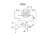
- FIG. 4 is a system diagram showing a power generation system 40 (40A) according to one embodiment.
- the power generation system 40 (40A) includes the fuel cell module 42 having the above configuration and the gas turbine 44 (rotating device).
- the oxidizing gas a is supplied to the compressor 46 that constitutes the gas turbine 44, and the oxidizing gas a is compressed by the compressor 46 and then supplied to the fuel cell module 42.
- the exhausted oxidizing gas a′ and the exhausted fuel gas f′ that have been used in the chemical reaction for power generation in the fuel cell module 42 are sent to the combustor 50 that constitutes the gas turbine 44, and the combustor 50 generates a high temperature Generates combustion gas.
- the rotary power generated by adiabatically expanding the combustion gas in the exhaust turbine 48 generates electric power in the generator 52, and the compressor 46 is driven by this rotary power to generate compressed gas.
- This compressed gas is supplied to the fuel cell module 42 as the oxidizing gas a.
- the fuel cell module 42 uses the compressed oxidizing gas a and the fuel gas f to generate electricity.
- the fuel cell module 42 since the fuel cell module 42 includes the plurality of fuel cell stacks 10 having improved oxidation resistance (robustness), durability can be improved and repair frequency can be reduced. As a result, the operation can be continued for a long time and the power generation efficiency can be improved. Moreover, since the compressed oxidizing gas a can be supplied to the fuel cell module 42, the power generation efficiency can be further improved. Further, since the combustor 50 is driven by the exhausted oxidizing gas a'exhausted from the fuel cell module 42 and the exhausted fuel gas f'to generate the rotational power, the required power of the power generation system 40 (40A) can be reduced. Furthermore, since both the fuel cell module 42 and the gas turbine 44 can generate power in a combined manner, the amount of power generation can be increased.
- FIG. 5 is a system diagram showing a power generation system 40 (40B) according to one embodiment.
- the power generation system 40 (40B) uses a turbocharger 54 as a rotating device.
- the oxidizing gas a is supplied to and compressed by the compressor 56 that constitutes the turbocharger 54, and the compressed oxidizing gas a is supplied to the fuel cell module 42.
- the exhausted oxidizing gas a′ and the exhausted fuel gas f′ that have been used in the chemical reaction for power generation in the fuel cell module 42 are sent to the exhaust turbine 58 that constitutes the turbocharger 54 and rotate the exhaust turbine 58. As a result, rotational power is generated.
- compressed gas is generated.
- the fuel cell module 42 is provided with the plurality of fuel cell stacks 10 having improved oxidation resistance (robustness), so that the durability of the module 42 can be improved and the repair frequency can be reduced. As a result, the operation can be continued for a long time and the power generation efficiency can be improved.
- Example 1 A CSZ material was selected for the substrate 12, and an appropriate amount of an extrusion molding binder and water were mixed, and the mixture was kneaded by a kneader and then extruded into a tube shape.
- a mixed material of NiO material and YSZ material was selected, an organic vehicle was added to this mixed material, and the mixture was kneaded with three rolls and then made into a slurry.
- the fuel side electrode 16 was formed into a film on the surface of the substrate 12 by screen printing using the slurry.
- a YSZ material was selected and an organic vehicle was added to form a slurry.
- the thickness of the solid electrolyte membrane 18 was 40 ⁇ m.
- a SrTiO 3 material was selected, and an organic vehicle was added thereto to form a slurry.
- the fuel-side electrode 16, the fuel-side electrode reaction layer 26, the solid electrolyte membrane 18, and the interconnector membrane 22 were sequentially formed on the surface of the substrate 12 by a screen printing method, and sintered at 1400 to 1450° C. (sintered body). ..
- the structure of film formation is as shown in FIG.
- a SrTiO 3 material was selected, and an organic vehicle was added to the material to form a slurry.
- a material having a LaSrMnO 3 composition was selected, and an organic vehicle was added thereto to form a slurry.
- An SDC material was selected for the oxygen-side electrode reaction layer 28, and an organic vehicle was added thereto to form a slurry.
- a LaSrCaMn-based material was selected, and an organic vehicle was added thereto to form a slurry.
- the porous ceramic film 24, the interconnector intermediate layer 30, the oxygen-side electrode reaction layer 28, and the oxygen-side electrode 20 were sequentially formed on the surface of the sintered body by a screen printing method, and fired at 1200 to 1300° C. (fired body ). Further, the fired body was subjected to a reduction treatment to produce a fuel cell unit 14.
- Example 2 The fuel cell unit 14 was produced by the same steps as in Example 1 except that the thickness of the solid electrolyte membrane 18 was 20 ⁇ m.
- a fuel cell 104 was produced in the same process as in Example 1 except that the porous ceramic membrane 24 was not formed.
- FIG. 6 is a graph showing the experimental results of Example 1, Example 2 and Comparative Example, which is a cylindrical cell stack in which the fuel cell 14 is made of SOFC.
- Example 1 and 2 in which the porous ceramic membrane 24 was formed, the voltage holding time of the fuel cell after encapsulation was longer than that in Comparative Example, and the solid electrolyte membrane 18 was thinned. It can be seen that in Example 2 as well, the voltage holding time is about the same as in Example 1. From this, it was confirmed that the porous ceramic film 24 on the interconnector film 22 can suppress damage to the solid electrolyte film 18 and the interconnector film 22 due to the inflow of the oxidizing gas a into the fuel side electrode 16.
- the oxidation resistance (robustness) of the fuel cells forming the fuel cell stack can be improved, and the oxidizing gas is generated even in an emergency stop when the supply of the fuel gas is interrupted. It is possible to suppress damage to the solid electrolyte membrane and the interconnector membrane due to penetration into the fuel-side electrode side.
- Fuel side electrode 16 (16a) Fuel side electrode (first fuel side electrode) 16 (16b) Fuel side electrode (second fuel side electrode) 18, 108 Solid electrolyte membrane 20, 110 Oxygen side electrode 22, 112 Interconnector membrane 24 Porous ceramic membrane 26 Fuel side electrode reaction layer 28 Oxygen side electrode reaction layer 30 Interconnector membrane intermediate layer 32 Inclined part 40 (40A, 40B) Power generation system 44 Gas turbine 46,56 Compressor 48,58 Exhaust turbine 50 Combustor 52 Generator 54 Turbocharger R0 Fuel side electrode area a Oxidizing gas a'Exhaust oxidizing gas f Fuel gas f'Exhaust fuel gas
Landscapes
- Chemical & Material Sciences (AREA)
- Engineering & Computer Science (AREA)
- Life Sciences & Earth Sciences (AREA)
- Manufacturing & Machinery (AREA)
- Sustainable Development (AREA)
- Sustainable Energy (AREA)
- Chemical Kinetics & Catalysis (AREA)
- Electrochemistry (AREA)
- General Chemical & Material Sciences (AREA)
- Composite Materials (AREA)
- Ceramic Engineering (AREA)
- Fuel Cell (AREA)
Abstract
一実施形態に係る燃料電池セルスタックは、基体と、基体上に積層された燃料側電極、固体電解質膜及び酸素側電極を夫々含む複数の燃料電池セルと、複数の燃料電池セルのうち隣り合う燃料電池セルの一方の前記燃料電池セルの燃料側電極と他方の燃料電池セルの酸素側電極とを電気的に接続するインタコネクタ膜と、隣り合う燃料電池セルの一方の燃料電池セルの第1の燃料側電極と他方の燃料電池セルの第2の燃料側電極との間の領域において、少なくともインタコネクタ膜を覆う多孔質セラミック膜とを備える。
Description
本開示は、燃料電池セルスタック、該燃料電池セルスタックを備える燃料電池モジュール、該燃料電池モジュールを備える発電システム及び燃料電池セルスタックを作製する方法に関する。
次世代エネルギとして、燃料側電極、電解質及び酸素側電極で構成される燃料電池セルを最小単位とし、燃料側電極に供給される燃料ガスと酸素側電極に供給される酸化性ガスとを化学反応させて発電する燃料電池が知られている。
このうち、固体酸化物形燃料電池(SOFC)(Solid Oxide Fuel Cell)は、電解質としてジルコニアセラミックスなどのセラミックスが用いられ、都市ガス、天然ガス、石油、メタノール、石炭ガス化ガスなどを燃料として運転される燃料電池である。このようなSOFCは、イオン伝導率を高めるために作動温度が約700~1000℃程度と高く、用途の広い高効率な高温型燃料電池として知られている。SOFCは、例えばガスタービンやマイクロガスタービン及びターボチャージャ等の回転機器と組み合わせ、運転圧力を高めることでより高効率の発電が可能となる。また、このような加圧発電システムにおいて、圧縮機から吐出される圧縮空気を酸化性ガスとしてSOFCの酸素側電極に供給すると共に、SOFCから排出される高温の排燃料ガスを、ガスタービンなどの回転機器入口の燃焼器に供給して燃焼させ、燃焼器で発生した高温の燃焼ガスで回転機器を回転させることで、動力の回収を図ることができる。
このうち、固体酸化物形燃料電池(SOFC)(Solid Oxide Fuel Cell)は、電解質としてジルコニアセラミックスなどのセラミックスが用いられ、都市ガス、天然ガス、石油、メタノール、石炭ガス化ガスなどを燃料として運転される燃料電池である。このようなSOFCは、イオン伝導率を高めるために作動温度が約700~1000℃程度と高く、用途の広い高効率な高温型燃料電池として知られている。SOFCは、例えばガスタービンやマイクロガスタービン及びターボチャージャ等の回転機器と組み合わせ、運転圧力を高めることでより高効率の発電が可能となる。また、このような加圧発電システムにおいて、圧縮機から吐出される圧縮空気を酸化性ガスとしてSOFCの酸素側電極に供給すると共に、SOFCから排出される高温の排燃料ガスを、ガスタービンなどの回転機器入口の燃焼器に供給して燃焼させ、燃焼器で発生した高温の燃焼ガスで回転機器を回転させることで、動力の回収を図ることができる。
燃料電池モジュールは、例えば、複数の燃料電池セルでセルスタックを形成し、容器内に収納された複数のセルスタックで発電室を形成するように構成される。燃料電池セルは、内部に燃料ガス通路と酸化性ガス通路を有し、該燃料ガス通路に燃料ガス供給管から燃料ガスを供給し、該酸化性ガス通路に酸化性ガス供給管から酸化性ガス(例えば空気)を供給する。
セルスタックは、燃料電池セルが担持される基体の形状によって、例えば、円筒形や平板形に形成される。特許文献1には、円筒形の基体管の表面に燃料電池セルを構成する各素材を塗布し焼成する円筒形セルスタックの製造方法が開示されている。
燃料電池の実用化においては、性能向上によるコスト低減と共に、燃料電池セルの耐酸化性(ロバスト性)の向上が求められる。SOFCなど固体電解質膜を備える燃料電池セルにおいては、固体電解質膜を薄膜化することで性能向上が図れるが、薄膜化により膜強度が低下するため、温度変化によって発生する熱応力などによってクラックが発生しやすくなる。クラックが発生すると、異常や故障が発生して燃料ガスの供給が停止した緊急時に、高温環境下で酸化性ガスが燃料側電極に侵入し、短時間で燃料側電極が酸化し損傷するおそれがある。
本開示に係る一実施形態は、燃料電池セルの耐酸化性(ロバスト性)を向上させることにより、燃料ガスの供給が遮断された非常停止時などにおいても、燃料電池セルを構成する固体電解質膜などの緻密膜が短時間で損傷するのを抑制することを目的とする。
(1)一実施形態に係る燃料電池セルスタックは、
基体と、
該基体上に積層された燃料側電極、固体電解質膜及び酸素側電極を夫々含む複数の燃料電池セルと、
前記複数の燃料電池セルのうち隣り合う前記燃料電池セルの一方の前記燃料電池セルの前記燃料側電極と他方の前記燃料電池セルの前記酸素側電極とを電気的に接続するインタコネクタ膜と、
隣り合う前記燃料電池セルの一方の前記燃料電池セルの第1の燃料側電極と他方の前記燃料電池セルの第2の燃料側電極との間の領域において、少なくとも前記インタコネクタ膜を覆う多孔質セラミック膜と、
を備える。
基体と、
該基体上に積層された燃料側電極、固体電解質膜及び酸素側電極を夫々含む複数の燃料電池セルと、
前記複数の燃料電池セルのうち隣り合う前記燃料電池セルの一方の前記燃料電池セルの前記燃料側電極と他方の前記燃料電池セルの前記酸素側電極とを電気的に接続するインタコネクタ膜と、
隣り合う前記燃料電池セルの一方の前記燃料電池セルの第1の燃料側電極と他方の前記燃料電池セルの第2の燃料側電極との間の領域において、少なくとも前記インタコネクタ膜を覆う多孔質セラミック膜と、
を備える。
一般に、燃料電池セルスタックを構成する複数の燃料電池セルの各々は、酸化性ガスを透過させない緻密膜で構成される固体電解質膜及びインタコネクタ膜が複数の燃料電池セルの燃料側電極を覆うように設けられることで、酸素側電極側の酸化性ガスが燃料側電極側へ侵入するのを防止するようにしている。しかし、隣り合う燃料電池セルの燃料側電極間の領域においては、燃料側電極の温度差による熱変化量が大きいために、局所的な応力が発生しやすい。特に、インタコネクタ膜の端部は他部材との熱膨張率の違いによって応力集中が生じやすい。そこで、上記(1)の構成によれば、隣り合う燃料電池セルの燃料側電極間の領域において、少なくともインタコネクタ膜を覆うように多孔質セラミック膜を設けることで、該多孔質セラミック膜が固体電解質膜やインタコネクタ膜に発生する応力を緩和し、上記緻密膜の損傷を抑制することで、燃料電池セルの耐酸化性(ロバスト性)を向上できる。
なお、ここで、「酸化性ガス」とは、酸素を略15%~30%含むガスであり、代表的には空気が好適であるが、空気以外にも燃焼排ガスと空気の混合ガスや、酸素と空気の混合ガスなどが使用できる。
多孔質セラミック膜はインタコネクタ膜を覆うように設けることでインタコネクタ膜の強度部材として機能し、燃料側電極の温度差により燃料側電極間領域の固体電解質膜やインタコネクタ膜に発生する応力を緩和する作用を有する。また、多孔質セラミック膜は緻密膜に比べ局部発生応力が小さく、たとえ固体電解質膜やインタコネクタ膜で微小なクラックが発生してもクラックの伸展を抑制できる。
(2)一実施形態では、前記(1)の構成において、
前記インタコネクタ膜は、前記燃料側電極間の領域で前記第1の燃料側電極から前記第2の燃料側電極に向かい、前記第2の燃料側電極の手前まで延在する。
上記(2)の構成によれば、インタコネクタ膜が、燃料側電極間領域に延在することで、燃料側電極間領域でインタコネクタ膜と多孔質セラミック膜の二層組織を形成できる。これによって、燃料側電極間領域で耐酸化性を向上できる。
前記インタコネクタ膜は、前記燃料側電極間の領域で前記第1の燃料側電極から前記第2の燃料側電極に向かい、前記第2の燃料側電極の手前まで延在する。
上記(2)の構成によれば、インタコネクタ膜が、燃料側電極間領域に延在することで、燃料側電極間領域でインタコネクタ膜と多孔質セラミック膜の二層組織を形成できる。これによって、燃料側電極間領域で耐酸化性を向上できる。
(3)一実施形態では、前記(1)の構成において、
前記インタコネクタ膜は、前記燃料側電極間の領域で前記第1の燃料側電極から前記第2の燃料側電極に向かい、前記第2の燃料側電極に達するまで延在する。
上記(3)の構成によれば、インタコネクタ膜は第1の燃料側電極から第2の燃料側電極に達するまで延在するため、燃料側電極間領域の全域を上記二層組織で覆うことができる。これによって、燃料側電極間領域で耐酸化性を向上できる。
前記インタコネクタ膜は、前記燃料側電極間の領域で前記第1の燃料側電極から前記第2の燃料側電極に向かい、前記第2の燃料側電極に達するまで延在する。
上記(3)の構成によれば、インタコネクタ膜は第1の燃料側電極から第2の燃料側電極に達するまで延在するため、燃料側電極間領域の全域を上記二層組織で覆うことができる。これによって、燃料側電極間領域で耐酸化性を向上できる。
(4)一実施形態では、前記(3)の構成において、
前記第2の燃料側電極は、前記第1の燃料側電極に向かって厚さが漸減する傾斜部を有し、前記インタコネクタ膜は前記傾斜部の傾斜領域中間部まで延在する。
上記(4)の構成によれば、インタコネクタ膜が第2の燃料側電極の傾斜部の傾斜領域中間部まで延在することで、燃料側電極間領域で耐酸化性を向上できる。また、インタコネクタ膜は上記傾斜部の中間部を越えて延在しないので、第2の燃料側電極側で形成される発電面積を減少させない。従って、発電性能の低下をまねかない。
前記第2の燃料側電極は、前記第1の燃料側電極に向かって厚さが漸減する傾斜部を有し、前記インタコネクタ膜は前記傾斜部の傾斜領域中間部まで延在する。
上記(4)の構成によれば、インタコネクタ膜が第2の燃料側電極の傾斜部の傾斜領域中間部まで延在することで、燃料側電極間領域で耐酸化性を向上できる。また、インタコネクタ膜は上記傾斜部の中間部を越えて延在しないので、第2の燃料側電極側で形成される発電面積を減少させない。従って、発電性能の低下をまねかない。
(5)一実施形態では、前記(4)の構成において、
前記インタコネクタ膜は、前記傾斜部の傾斜方向30%以上70%以下の領域まで延在する。
上記(5)の構成によれば、インタコネクタ膜が第2の燃料側電極の傾斜部の傾斜方向30~70%の領域まで延在するため、燃料側電極間領域の耐酸化性を向上できると共に、発電性能の低下をまねかない。
前記インタコネクタ膜は、前記傾斜部の傾斜方向30%以上70%以下の領域まで延在する。
上記(5)の構成によれば、インタコネクタ膜が第2の燃料側電極の傾斜部の傾斜方向30~70%の領域まで延在するため、燃料側電極間領域の耐酸化性を向上できると共に、発電性能の低下をまねかない。
(6)一実施形態では、前記(1)~(5)の何れかの構成において、
前記多孔質セラミック膜は、前記燃料側電極間の領域で前記第1の燃料側電極から前記第2の燃料側電極に向かい、前記第2の燃料側電極まで延在し、
前記第2の燃料側電極は、前記第1の燃料側電極に向かって厚さが漸減する傾斜部を有し、前記多孔質セラミック膜は前記傾斜部の少なくとも一部の領域まで延在する。
上記(6)の構成によれば、多孔質セラミック膜は、第1の燃料側電極から第2の燃料側電極の傾斜部の少なくとも一部の領域まで延在するので、燃料側電極間領域において発生する応力を緩和し、緻密膜の損傷を抑制することで、耐酸化性を向上できる。他方、多孔質セラミック膜は、第2の燃料側電極の傾斜部を越えて第2の燃料側電極側へ延在しないので、第2の燃料側電極側の発電性能を低下させない。
前記多孔質セラミック膜は、前記燃料側電極間の領域で前記第1の燃料側電極から前記第2の燃料側電極に向かい、前記第2の燃料側電極まで延在し、
前記第2の燃料側電極は、前記第1の燃料側電極に向かって厚さが漸減する傾斜部を有し、前記多孔質セラミック膜は前記傾斜部の少なくとも一部の領域まで延在する。
上記(6)の構成によれば、多孔質セラミック膜は、第1の燃料側電極から第2の燃料側電極の傾斜部の少なくとも一部の領域まで延在するので、燃料側電極間領域において発生する応力を緩和し、緻密膜の損傷を抑制することで、耐酸化性を向上できる。他方、多孔質セラミック膜は、第2の燃料側電極の傾斜部を越えて第2の燃料側電極側へ延在しないので、第2の燃料側電極側の発電性能を低下させない。
(7)一実施形態では、前記(6)の構成において、
前記多孔質セラミック膜は前記傾斜部の傾斜方向1/2以下の領域まで延在する。
上記(7)の構成によれば、多孔質セラミック膜は、第1の燃料側電極から第2の燃料側電極の傾斜部の傾斜方向1/2以下の領域まで延在するので、燃料側電極間領域の耐酸化性を向上できると共に、上記傾斜部の傾斜方向1/2を越えて第2の燃料側電極側へ延在しないので、第2の燃料側電極の外側に設けられた酸素側電極の薄肉化をまねかず、そのため、酸素側電極の性能低下をまねかない。
前記多孔質セラミック膜は前記傾斜部の傾斜方向1/2以下の領域まで延在する。
上記(7)の構成によれば、多孔質セラミック膜は、第1の燃料側電極から第2の燃料側電極の傾斜部の傾斜方向1/2以下の領域まで延在するので、燃料側電極間領域の耐酸化性を向上できると共に、上記傾斜部の傾斜方向1/2を越えて第2の燃料側電極側へ延在しないので、第2の燃料側電極の外側に設けられた酸素側電極の薄肉化をまねかず、そのため、酸素側電極の性能低下をまねかない。
(8)一実施形態では、前記(1)~(7)の何れかの構成において、
前記固体電解質膜は、前記燃料側電極間の領域において、前記インタコネクタ膜より前記基体側に設けられると共に、前記第2の燃料側電極から前記第1の燃料側電極まで延在する。
上記(8)の構成によれば、固体電解質膜が燃料側電極間領域に延在するので、燃料側電極間領域で膜厚が厚い固体電解質膜を形成できる。これによって燃料側電極間領域の固体電解質膜の強度を高めることができ、耐酸化性を向上できる。
前記固体電解質膜は、前記燃料側電極間の領域において、前記インタコネクタ膜より前記基体側に設けられると共に、前記第2の燃料側電極から前記第1の燃料側電極まで延在する。
上記(8)の構成によれば、固体電解質膜が燃料側電極間領域に延在するので、燃料側電極間領域で膜厚が厚い固体電解質膜を形成できる。これによって燃料側電極間領域の固体電解質膜の強度を高めることができ、耐酸化性を向上できる。
(9)一実施形態では、前記(1)~(8)の何れかの構成において、
前記多孔質セラミック膜は気孔率が10%以上60%以下の材料で構成される。
上記(9)の構成によれば、多孔質セラミック膜は気孔率が10%以上の材料で構成されるため、燃料側電極間領域で発生する応力を緩和でき、60%以下とすることで酸素のガス拡散による透過量を低減できる。また、該多孔質セラミック膜は局所的な応力が発生しにくいので、たとえ固体電解質膜やインタコネクタ膜でクラックが発生しても、多孔質セラミック膜でクラックの伸展を食い止めることができる。
前記多孔質セラミック膜は気孔率が10%以上60%以下の材料で構成される。
上記(9)の構成によれば、多孔質セラミック膜は気孔率が10%以上の材料で構成されるため、燃料側電極間領域で発生する応力を緩和でき、60%以下とすることで酸素のガス拡散による透過量を低減できる。また、該多孔質セラミック膜は局所的な応力が発生しにくいので、たとえ固体電解質膜やインタコネクタ膜でクラックが発生しても、多孔質セラミック膜でクラックの伸展を食い止めることができる。
(10)一実施形態では、前記(1)~(9)の何れかの構成において、
前記インタコネクタ膜は気孔率が0.1%以上5%以下の材料で構成される。
上記(10)の構成によれば、インタコネクタ膜は0.1%以上の気孔率を有しているため微小なクラックの伸展を低減でき、かつ5%以下の気孔率であるため膜を貫通する気孔はなく、燃料側電極間領域を含め、酸化性ガスの侵入を抑制でき、燃料電池セルの耐酸化性を向上できる。
前記インタコネクタ膜は気孔率が0.1%以上5%以下の材料で構成される。
上記(10)の構成によれば、インタコネクタ膜は0.1%以上の気孔率を有しているため微小なクラックの伸展を低減でき、かつ5%以下の気孔率であるため膜を貫通する気孔はなく、燃料側電極間領域を含め、酸化性ガスの侵入を抑制でき、燃料電池セルの耐酸化性を向上できる。
(11)一実施形態では、前記(1)~(10)の何れかの構成において、
前記固体電解質膜は、膜厚が5μm以上20μm以下で構成される。
上記(11)の構成によれば、固体電解質膜は膜厚が20μm以下の薄い膜で構成されるため、従来より発電性能を向上できるとともに、5μm以上なので必要な膜強度を維持できる。
前記固体電解質膜は、膜厚が5μm以上20μm以下で構成される。
上記(11)の構成によれば、固体電解質膜は膜厚が20μm以下の薄い膜で構成されるため、従来より発電性能を向上できるとともに、5μm以上なので必要な膜強度を維持できる。
(12)一実施形態では、前記(1)~(11)の何れかの構成において、
前記多孔質セラミック膜と前記インタコネクタ膜とは同じ材質である。
上記(12)の構成によれば、多孔質セラミック膜は固体電解質膜及びインタコネクタ膜の応力を緩和でき、酸素ガス透過性を低くでき、還元ガスの影響で膨張しないようにすることができる。
前記多孔質セラミック膜と前記インタコネクタ膜とは同じ材質である。
上記(12)の構成によれば、多孔質セラミック膜は固体電解質膜及びインタコネクタ膜の応力を緩和でき、酸素ガス透過性を低くでき、還元ガスの影響で膨張しないようにすることができる。
(13)一実施形態に係る燃料電池モジュールは、
前記(1)~(12)の何れかの構成を有する燃料電池セルスタックを複数集合させて構成される。
上記(13)の構成によれば、耐酸化性(ロバスト性)を向上させた燃料電池セルスタックを備えるため、耐久性を向上できる。これによって、補修頻度を低減でき、運転を長く継続できるので、発電効率を向上できる。
前記(1)~(12)の何れかの構成を有する燃料電池セルスタックを複数集合させて構成される。
上記(13)の構成によれば、耐酸化性(ロバスト性)を向上させた燃料電池セルスタックを備えるため、耐久性を向上できる。これによって、補修頻度を低減でき、運転を長く継続できるので、発電効率を向上できる。
(14)一実施形態に係る発電システムは、
前記(13)の構成を有する燃料電池モジュールと、
前記燃料電池モジュールから排気される排燃料ガスと排酸化性ガスとを用いて回転動力を発生させる回転機器と、
を備え、
前記燃料電池モジュールには、前記回転動力を用いて圧縮された前記酸化性ガスが供給され、前記燃料電池モジュールは、前記燃料ガスと前記圧縮された酸化性ガスを用いて発電する。
上記(14)の構成によれば、本開示に係る上記目的を達成しつつ、燃料電池モジュールに圧縮された酸化性ガスを供給できるので、発電効率を向上できると共に、燃料電池モジュールから排気される排燃料ガスと排酸化性ガスとを用いて回転動力を発生させるため、発電効率を向上できると共に、発電システムの所要動力を低減できる。
前記(13)の構成を有する燃料電池モジュールと、
前記燃料電池モジュールから排気される排燃料ガスと排酸化性ガスとを用いて回転動力を発生させる回転機器と、
を備え、
前記燃料電池モジュールには、前記回転動力を用いて圧縮された前記酸化性ガスが供給され、前記燃料電池モジュールは、前記燃料ガスと前記圧縮された酸化性ガスを用いて発電する。
上記(14)の構成によれば、本開示に係る上記目的を達成しつつ、燃料電池モジュールに圧縮された酸化性ガスを供給できるので、発電効率を向上できると共に、燃料電池モジュールから排気される排燃料ガスと排酸化性ガスとを用いて回転動力を発生させるため、発電効率を向上できると共に、発電システムの所要動力を低減できる。
(15)一実施形態では、前記(14)の構成において、
前記回転機器は、ガスタービン又はターボチャージャで構成される。
上記(15)の構成によれば、発電効率の向上及び発電システムの所要動力低減に加えて、回転機器がガスタービンである場合、燃料電池モジュールとガスタービンとで複合発電が可能になる。
前記回転機器は、ガスタービン又はターボチャージャで構成される。
上記(15)の構成によれば、発電効率の向上及び発電システムの所要動力低減に加えて、回転機器がガスタービンである場合、燃料電池モジュールとガスタービンとで複合発電が可能になる。
(16)一実施形態に係る燃料電池セルスタックを作製する方法は、
基板上に、燃料側電極と、燃料側電極反応層と、固体電解質膜と、インタコネクタ膜とを成膜し焼結させて焼結体を得るステップと、
前記焼結体上に、多孔質セラミック膜と、インタコネクタ中間層と、酸素側電極反応層と、酸素側電極とを成膜して焼成して焼成体を得るステップと、
前記焼成体に還元処理を施すステップと
を含む。
上記(16)の方法によれば、前記(1)~(12)のいずれかの燃料電池セルスタックを作製することができる。
基板上に、燃料側電極と、燃料側電極反応層と、固体電解質膜と、インタコネクタ膜とを成膜し焼結させて焼結体を得るステップと、
前記焼結体上に、多孔質セラミック膜と、インタコネクタ中間層と、酸素側電極反応層と、酸素側電極とを成膜して焼成して焼成体を得るステップと、
前記焼成体に還元処理を施すステップと
を含む。
上記(16)の方法によれば、前記(1)~(12)のいずれかの燃料電池セルスタックを作製することができる。
幾つかの実施形態によれば、燃料ガスの供給が遮断された非常停止時などにおいても酸化性ガスが燃料側電極側に侵入することによる固体電解質膜及びインタコネクタ膜の損傷を抑制し、燃料電池セルの耐酸化性(ロバスト性)を向上させることができる。
以下、添付図面を参照して、本発明の幾つかの実施形態について説明する。ただし、これらの実施形態に記載されている又は図面に示されている構成部品の寸法、材質、形状及びその相対的配置等は、本発明の範囲をこれに限定する趣旨ではなく、単なる説明例にすぎない。
例えば、「ある方向に」、「ある方向に沿って」、「平行」、「直交」、「中心」、「同心」或いは「同軸」等の相対的或いは絶対的な配置を表す表現は、厳密にそのような配置を表すのみならず、公差、若しくは、同じ機能が得られる程度の角度や距離をもって相対的に変位している状態も表すものとする。
例えば、「同一」、「等しい」及び「均質」等の物事が等しい状態であることを表す表現は、厳密に等しい状態を表すのみならず、公差、若しくは、同じ機能が得られる程度の差が存在している状態も表すものとする。
例えば、四角形状や円筒形状等の形状を表す表現は、幾何学的に厳密な意味での四角形状や円筒形状等の形状を表すのみならず、同じ効果が得られる範囲で、凹凸部や面取り部等を含む形状も表すものとする。
一方、一つの構成要素を「備える」、「具える」、「具備する」、「含む」、又は「有する」という表現は、他の構成要素の存在を除外する排他的な表現ではない。
例えば、「ある方向に」、「ある方向に沿って」、「平行」、「直交」、「中心」、「同心」或いは「同軸」等の相対的或いは絶対的な配置を表す表現は、厳密にそのような配置を表すのみならず、公差、若しくは、同じ機能が得られる程度の角度や距離をもって相対的に変位している状態も表すものとする。
例えば、「同一」、「等しい」及び「均質」等の物事が等しい状態であることを表す表現は、厳密に等しい状態を表すのみならず、公差、若しくは、同じ機能が得られる程度の差が存在している状態も表すものとする。
例えば、四角形状や円筒形状等の形状を表す表現は、幾何学的に厳密な意味での四角形状や円筒形状等の形状を表すのみならず、同じ効果が得られる範囲で、凹凸部や面取り部等を含む形状も表すものとする。
一方、一つの構成要素を「備える」、「具える」、「具備する」、「含む」、又は「有する」という表現は、他の構成要素の存在を除外する排他的な表現ではない。
図1は一実施形態に係る燃料電池セルスタックの縦断面を模式的に示し、図2及び図3は、幾つかの実施形態に係る燃料電池セルスタックの縦断面図である。図7は、従来の燃料電池セルスタックの縦断面図である。
図1~図3において、幾つかの実施形態に係る燃料電池セルスタック10(10A、10B、10C)は、基体12と、基体12上に担持された複数の燃料電池セル14とを備える。複数の燃料電池セル14の各々は、基体12側から順に積層された膜状の燃料側電極16、固体電解質膜18及び酸素側電極20を備える。隣り合う燃料電池セル14の燃料側電極16と酸素側電極20とは、導電性を有するインタコネクタ膜22によって電気的に接続されている。インタコネクタ膜22によって、基体12に担持される複数の燃料電池セル14は電気的に直列に接続される。
基体12側に燃料ガスfが流れる流路が形成され、酸素側電極20側に酸化性ガスaが流れる流路が形成される。酸化性ガスaとして例えば空気が用いられる。燃料ガスf及び酸化性ガスaを原料とし、燃料側電極16及び酸素側電極20で夫々起こる化学反応によって、酸素イオンが固体電解質膜18を透過し発電が起る。インタコネクタ膜22によって電気的に直列接続された電力は、基体12の端部に設けられたリード膜(不図示)によって取り出される。燃料電池モジュールは、複数のセルスタック10で構成される発電室を備える。各燃料電池セル14は、隣り合う燃料電池セル14の燃料側電極16間の領域R0(図1参照)において、少なくともインタコネクタ膜22を覆う多孔質セラミック膜24を備える。
酸化性ガスaを透過させない緻密膜で構成される固体電解質膜18及びインタコネクタ膜22が複数の燃料電池セル14の燃料側電極を覆うように設けられるため、酸素側電極20側の酸化性ガスaが燃料側電極16側へ侵入するのを防止している。しかし、隣り合う燃料電池セル14の燃料側電極間領域R0においては、燃料側電極16の温度差による熱変化量が大きいために、局所的な応力が発生しやすく、特に、インタコネクタ膜22の端部は他部材との熱膨張率の違いや焼成時の熱膨張率の違い等によって応力集中が起りやすい。
以下、燃料電池セルスタック10に異常や故障が発生して燃料ガスの供給が遮断された負荷遮断時に、燃料電池セル14が損傷するメカニズムを説明する。
(1)負荷が遮断されると発電に伴う発熱がなくなるため燃料電池セル14(固体電解質膜18付近)の温度が急激に低下して収縮し、これによって、領域R0に引張り応力が発生する。固体電解質膜18及びインタコネクタ膜22の膜厚が小さいと、これらの緻密膜にクラックが発生する。なお、基体12は熱容量が他の構成材料にくらべ圧倒的に熱容量が大きく基本的に温度変化しない。
↓
(2)クラックを通して酸素側電極20側から酸素が燃料側電極16側に侵入し、燃料側電極16が酸化され、体積が膨張する。
↓
(3)燃料側電極16の体積膨張によって燃料側電極16に接する固体電解質膜18にクラックが発生し、燃料ガスfのリークが発生する。
↓
(4)燃料電池セル14でリークした燃料ガスfが燃焼し、燃料電池セル14の性能が低下し、損傷が拡大する。
(1)負荷が遮断されると発電に伴う発熱がなくなるため燃料電池セル14(固体電解質膜18付近)の温度が急激に低下して収縮し、これによって、領域R0に引張り応力が発生する。固体電解質膜18及びインタコネクタ膜22の膜厚が小さいと、これらの緻密膜にクラックが発生する。なお、基体12は熱容量が他の構成材料にくらべ圧倒的に熱容量が大きく基本的に温度変化しない。
↓
(2)クラックを通して酸素側電極20側から酸素が燃料側電極16側に侵入し、燃料側電極16が酸化され、体積が膨張する。
↓
(3)燃料側電極16の体積膨張によって燃料側電極16に接する固体電解質膜18にクラックが発生し、燃料ガスfのリークが発生する。
↓
(4)燃料電池セル14でリークした燃料ガスfが燃焼し、燃料電池セル14の性能が低下し、損傷が拡大する。
本実施形態では、領域R0において、多孔質セラミック膜24が少なくともインタコネクタ膜22を覆うように設けられるため、インタコネクタ膜22の強度部材として機能し、燃料側電極16の温度差により燃料側電極間領域の固体電解質膜18やインタコネクタ膜22に発生する応力を緩和する作用を有する。また、多孔質セラミック膜24は局所的な応力が発生しにくいので、たとえ固体電解質膜18又はインタコネクタ膜22で微細なクラックが発生しても、クラックの伸展を抑制できるため、多孔質セラミック膜24が酸化性ガスaの侵入を抑制できる。こうして、燃料電池セル14の耐酸化性(ロバスト性)を向上できる。
図1において、隣り合う燃料側電極16間に形成される領域R0(O)は、燃料側電極16の温度差による熱変化量が大きいために、局所的な応力が発生しやすい領域である。領域R1(X)は、燃料電池セル14の発電性能に影響しない領域であり、この領域に多孔質セラミック膜24が設けられており、領域R1に多孔質セラミック膜24が設けられても、発電性能に影響しない。領域R2(O+M+N)は、発電性能への影響が軽微である領域であり、領域R3(O+M+N+P)は、発電性能への影響を少なくできる最大領域である。インタコネクタ膜22及び多孔質セラミック膜24の設置領域が領域Pを越えると、発電性能が低下する。
燃料電池セル14を構成する各素子の厚さはミクロン単位で構成される。各素子のうち酸素側電極20の膜厚が最大である。多孔質セラミック膜24は、20~100μm程度とするのがよい。これより薄いと応力緩和効果が低減し、逆に厚過ぎると酸素側電極20が薄肉化し、酸素側電極20の性能が低下するおそれがある。
一実施形態では、多孔質セラミック膜24はインタコネクタ膜22と同一材料で構成される。多孔質セラミック膜24は、還元膨張性、熱膨張率及び耐酸化性でインタコネクタ膜22と同様の性質が求められるので、インタコネクタ膜22と同一材料とするのがよい。例えば、インタコネクタ膜22及び多孔質セラミック膜24にSrTiO3系の材料を用いる。また、多孔質セラミック膜24は、還元雰囲気に晒されることを考慮した材料を用いるとよい。例えば、インタコネクタ膜22及び多孔質セラミック膜24にランタンクロマイトやSrTiO3等を用いる。
図7は、従来の燃料電池セルスタック100を示す。燃料電池セルスタック100は、基体102と、基体102上に担持された複数の燃料電池セル104とを備える。複数の燃料電池セル104は、夫々基体102側から順に積層された燃料側電極106、固体電解質膜108及び酸素側電極110を備える。隣り合う燃料電池セル104の燃料側電極106と酸素側電極110とは、導電性を有するインタコネクタ膜112によって電気的に接続されている。これによって、基体102に担持される複数の燃料電池セル104は電気的に直列に接続される。
基体102側に燃料ガスfが流れる流路が形成され、酸素側電極110側に酸化性ガスaが流れる流路が形成される。そして、燃料電池セルスタック10と同様に、燃料ガスf及び酸化性ガスaを原料とし、燃料側電極106及び酸素側電極110で夫々起こる化学反応によって、酸素イオンが固体電解質膜108を透過し発電が起る。基体102毎にインタコネクタ膜112によって取り出された電力は、基体102の端部に設けられたリード膜(不図示)によって取り出される。燃料電池セルスタック100は、多孔質セラミック膜24を備えていないため、図1~図3に示す実施形態と比べて、耐酸化性(ロバスト性)が劣る。
一実施形態では、図1に示すように、燃料側電極16と固体電解質膜18との間に燃料側電極反応層26を介在させる。また、固体電解質膜18と酸素側電極20との間に酸素側電極反応層28を介在させる。さらに、インタコネクタ膜22と酸素側電極20との間にインタコネクタ中間層30を介在させる。これらの反応層及び中間層は各素子間の接合面の反応抵抗を低減するために設けられる。
一実施形態では、図1及び図2に示す燃料電池セルスタック10(10A、10B)において、インタコネクタ膜22は、領域R0で燃料側電極16(16a)(第1の燃料側電極)から燃料側電極16(16b)(第2の燃料側電極)に向かい、燃料側電極16(16b)の手前まで延在する。
この実施形態によれば、インタコネクタ膜22が、領域R0に延在することで、領域R0でインタコネクタ膜22と多孔質セラミック膜24の二層組織を形成できる。これによって、領域R0で燃料側電極側への酸化性ガスaの侵入を抑制でき、耐酸化性を向上できる。
この実施形態によれば、インタコネクタ膜22が、領域R0に延在することで、領域R0でインタコネクタ膜22と多孔質セラミック膜24の二層組織を形成できる。これによって、領域R0で燃料側電極側への酸化性ガスaの侵入を抑制でき、耐酸化性を向上できる。
一実施形態では、図3に示す燃料電池セルスタック10(10C)において、インタコネクタ膜22は、領域R0で燃料側電極16(16a)から燃料側電極16(16b)に向かい、燃料側電極16(16b)に達するまで延在する。
この実施形態によれば、領域R0の全域をインタコネクタ膜22及び多孔質セラミック膜24の二層組織で覆うことができるので、領域R0で燃料側電極16側への酸化性ガスaの侵入を抑制でき、耐酸化性を向上できる。
この実施形態によれば、領域R0の全域をインタコネクタ膜22及び多孔質セラミック膜24の二層組織で覆うことができるので、領域R0で燃料側電極16側への酸化性ガスaの侵入を抑制でき、耐酸化性を向上できる。
一実施形態では、図3に示すように、燃料側電極16(16b)は、燃料側電極16(16a)に向かって厚さが漸減する傾斜部32を有し、インタコネクタ膜22は傾斜部32の傾斜領域中間部まで延在する。
この実施形態によれば、インタコネクタ膜22が傾斜部32の傾斜領域中間部まで延在するため、領域R0における酸化性ガスaの侵入を抑制できると共に、傾斜部32の中間部を越えて延在しないので、燃料側電極16(16b)側で形成される発電面積を減少させない。そのため、発電性能が低下しない。
この実施形態によれば、インタコネクタ膜22が傾斜部32の傾斜領域中間部まで延在するため、領域R0における酸化性ガスaの侵入を抑制できると共に、傾斜部32の中間部を越えて延在しないので、燃料側電極16(16b)側で形成される発電面積を減少させない。そのため、発電性能が低下しない。
一実施形態では、インタコネクタ膜22は、傾斜部32の傾斜方向30%以上70%以下の領域まで延在する。
この実施形態によれば、インタコネクタ膜22が傾斜部32の傾斜方向30~70%の領域まで延在するため、領域R0の耐酸化性を向上できると共に、燃料側電極16(16b)側の発電性能が低下しない。
この実施形態によれば、インタコネクタ膜22が傾斜部32の傾斜方向30~70%の領域まで延在するため、領域R0の耐酸化性を向上できると共に、燃料側電極16(16b)側の発電性能が低下しない。
一実施形態では、図2及び図3に示すように、多孔質セラミック膜24は、領域R0で燃料側電極16(16a)から燃料側電極16(16b)に向かって燃料側電極16(16b)まで延在し、かつ燃料側電極16(16b)の傾斜部32の少なくとも一部の領域まで延在している。
この実施形態によれば、多孔質セラミック膜24は、領域R0において固体電解質膜18及びインタコネクタ膜22に発生する応力を緩和し、固体電解質膜18及びインタコネクタ膜22等の緻密膜の損傷を抑制するため、燃料電池セル14の耐酸化性を向上できる。他方、多孔質セラミック膜24は、傾斜部32を越えて燃料側電極16(16b)側へ延在しないので、燃料側電極16(16b)側で起こる発電反応による発電性能を低下させない。
この実施形態によれば、多孔質セラミック膜24は、領域R0において固体電解質膜18及びインタコネクタ膜22に発生する応力を緩和し、固体電解質膜18及びインタコネクタ膜22等の緻密膜の損傷を抑制するため、燃料電池セル14の耐酸化性を向上できる。他方、多孔質セラミック膜24は、傾斜部32を越えて燃料側電極16(16b)側へ延在しないので、燃料側電極16(16b)側で起こる発電反応による発電性能を低下させない。
一実施形態では、多孔質セラミック膜24は傾斜部32の傾斜方向1/2以下の領域まで延在する。この実施形態によれば、多孔質セラミック膜24によって領域R0の耐酸化性を向上できると共に、傾斜部32の傾斜方向1/2を越えて燃料側電極16(16b)側へ延在しないので、燃料側電極16(16b)の外側に設けられた酸素側電極20の薄肉化をまねかず、従って、酸素側電極20の性能低下をまねかない。
一実施形態では、固体電解質膜18は、領域R0において、インタコネクタ膜22より基体12側に設けられると共に、燃料側電極16(16b)から燃料側電極16(16a)まで延在する。
この実施形態によれば、固体電解質膜18が領域R0に充填されるため、領域R0で膜厚が大きい固体電解質膜を形成できる。これによって、燃料側電極間領域の固体電解質膜18の強度を高めることができ、燃料電池セル14の耐酸化性を向上できる。
この実施形態によれば、固体電解質膜18が領域R0に充填されるため、領域R0で膜厚が大きい固体電解質膜を形成できる。これによって、燃料側電極間領域の固体電解質膜18の強度を高めることができ、燃料電池セル14の耐酸化性を向上できる。
一実施形態では、多孔質セラミック膜24は気孔率が10%以上の材料で構成されるため、燃料側電極間領域で発生する応力を緩和でき、他方、60%以下とすることで酸素のガス拡散による透過量を低減できる。また、多孔質セラミック膜24は局所的な応力が発生しにくいので、たとえ固体電解質膜18やインタコネクタ膜22でクラックが発生しても、多孔質セラミック膜24でクラックの伸展を食い止めることができる。
一実施形態では、インタコネクタ膜22は気孔率が0.1~5%の材料で構成される。この構成によれば、インタコネクタ膜22は0.1%以上の気孔率を有しているため微小なクラックの伸展を低減でき、かつ5%以下の気孔率であるため膜を貫通する気孔はなく、燃料側電極間領域R0を含め、酸化性ガスaの侵入を抑制でき、燃料電池セル14の耐酸化性を向上できる。これによって、インタコネクタ膜22は領域R0を含め、酸化性ガスaの侵入を抑制でき、燃料電池セル14の耐酸化性を向上できる。
一実施形態では、固体電解質膜18は、膜厚(端部ではなく基体12の表面に沿う方向における中央部の膜厚)が5~20μmの膜状体で構成される。固体電解質膜18を20μm以下とすることで従来より薄肉化されるため、発電性能を向上できると共に、5μm以上とすることで、必要な膜強度を確保できる。
一実施形態では、基体12は内側流路に燃料ガスfが供給される基体管で構成される。燃料電池セルスタック10は該基体管に複数の燃料電池セル14が担持されて構成されるため、円筒形のセルスタックを形成する。
なお、別な実施形態では、燃料電池セルスタックは、平板形を有する基体に複数の燃料電池セル14を担持した平板形又は扁平円筒形のセルスタックであってもよい。
なお、別な実施形態では、燃料電池セルスタックは、平板形を有する基体に複数の燃料電池セル14を担持した平板形又は扁平円筒形のセルスタックであってもよい。
一実施形態では、燃料電池セル14は、固体電解質膜18が固体酸化物で構成されるSOFCで構成される。SOFCは、650~1000℃の高温で運転され、非常停止時に電流が遮断されると発電による発熱がなくなるため燃料電池セル14付近の温度が急激に低下する。そのため、これにより領域R0に引張り応力が発生し、領域R0の固体電解質膜18やインタコネクタ膜22にクラックが発生し耐酸化性が低下する。これに対し、上記幾つかの実施形態によれば、耐酸化性を高めることができるので、非常停止時に電流が遮断されても、酸化性ガスaが燃料側電極16側に達して固体電解質膜18やインタコネクタ膜22の損傷を抑制することができる。
基体12は燃料電池セルの強度を保持するため、厚み1~3mm程度、燃料を通すため多孔質であること(気孔率30~50%程度)が望ましい。絶縁性を有する必要があるため、材質としては、CSZ、MgAl2O4、SrZrO3等が用いられる。
燃料側電極16は電子導電性が高いこと、熱膨張係数が固体電解質膜18と同程度であること、多孔質であること、還元雰囲気で安定であることが要求される。この観点から、材質は、Niとジルコニア系酸化物のサーメット、Niとセリア系酸化物等が好ましい。また、気孔率30~50%、厚みは50~200μm程度が好ましい。
固体電解質膜18は燃料と空気を遮断すること、酸素イオンを通すことが要求される。この観点から材質はYSZ、ScSZ、LSGM、セリア系酸化物が好ましく、気孔率は0.1~5%程度、厚みは5~50μm(高出力化のためには5~20μm程度)が好ましい。
酸素側電極20は電子導電性が高いこと、熱膨張係数が固体電解質膜18と同程度であること、多孔質であること、酸化雰囲気で安定であることが要求される。この観点から、材質は、ランタンマンガナイト系、ランタンコバルト系、ランタン鉄系材料が好ましく、気孔率は30~50%程度、厚みは100~1000μm程度が好ましい。
インタコネクタ膜22は燃料と空気を遮断すること、電子導電性が高いこと、固体電解質膜18との熱膨張係数が近いことが要求される。この観点から、SrTiO3系材料、ランタンクロマイト系材料が好ましく、気孔率は0.1~5%程度、厚みは10~50μm程度が好ましい。
多孔質セラミック膜24は固体電解質膜18及びインタコネクタ膜22の応力を緩和できること、材料自身では酸素ガス透過性が低いこと、還元ガスの影響で膨張しないことが要求される。この観点からインタコネクタ膜22と同じ材質が好ましく、SrTiO3系材料、ランタンクロマイト系材料等が用いられる。気孔率は10~60%、厚みは20~100μm程度が好ましい。
一実施形態に係る燃料電池モジュール42は、図4及び図5に示すように、上記各実施形態に係る燃料電池セルスタック10を複数集合させて構成される。この燃料電池モジュール42によれば、耐酸化性(ロバスト性)を向上させた複数の燃料電池セルスタック10を備えるため、耐久性を向上できる。これによって、補修頻度を低減でき、運転を長く継続できるので、発電効率を向上できる。
燃料電池モジュールは、GTCC(Gas Turbine Combined Cycle:ガスタービンコンバインドサイクル発電)、MGT(Micro Gas Turbine:マイクロガスタービン)、又はターボチャージャと組み合わされて利用される複合発電システムに適用されることがある。
図4は、一実施形態に係る発電システム40(40A)を示す系統図である。図4において、発電システム40(40A)は、上記構成の燃料電池モジュール42と、ガスタービン44(回転機器)とを備える。ガスタービン44を構成する圧縮機46に酸化性ガスaが供給され、酸化性ガスaは圧縮機46で圧縮された後、燃料電池モジュール42に供給される。燃料電池モジュール42で発電のための化学反応に用いられた後の排酸化性ガスa’及び排燃料ガスf’は、ガスタービン44を構成する燃焼器50に送られ、燃焼器50で高温の燃焼ガスを生成する。この燃焼ガスを排気タービン48で断熱膨張させることにより発生する回転動力により、発電機52で電力が生成されると共に、この回転動力により圧縮機46を駆動することで、圧縮ガスが発生する。この圧縮ガスを酸化性ガスaとして燃料電池モジュール42に供給する。燃料電池モジュール42は、圧縮された酸化性ガスaと燃料ガスfを用いて発電する。
上記構成によれば、燃料電池モジュール42内に耐酸化性(ロバスト性)を向上させた複数の燃料電池セルスタック10を備えるため、耐久性を向上でき、補修頻度を低減できる。これによって、運転を長く継続でき、発電効率を向上できる。また、燃料電池モジュール42に圧縮された酸化性ガスaを供給できるので、さらに発電効率を向上できる。また、燃料電池モジュール42から排気される排酸化性ガスa’と排燃料ガスf’で燃焼器50を駆動させて回転動力を発生させるため、発電システム40(40A)の所要動力を低減できる。さらに、燃料電池モジュール42とガスタービン44の両方で複合的に発電できるので、発電量を増加できる。
図5は、一実施形態に係る発電システム40(40B)を示す系統図である。発電システム40(40B)は、回転機器としてターボチャージャ54が用いられる。図5において、ターボチャージャ54を構成する圧縮機56に酸化性ガスaを供給して圧縮し、圧縮された酸化性ガスaを燃料電池モジュール42に供給する。燃料電池モジュール42で発電のための化学反応に用いられた後の排酸化性ガスa’及び排燃料ガスf’は、ターボチャージャ54を構成する排気タービン58に送られ、排気タービン58を回転させて回転動力が発生する。この回転動力で圧縮機56を駆動することで、圧縮ガスが発生する。
この実施形態によれば、燃料電池モジュール42内に耐酸化性(ロバスト性)を向上させた複数の燃料電池セルスタック10を備えるため、モジュール42の耐久性を向上でき、補修頻度を低減できる。これによって、運転を長く継続でき、発電効率を向上できる。
この実施形態によれば、燃料電池モジュール42内に耐酸化性(ロバスト性)を向上させた複数の燃料電池セルスタック10を備えるため、モジュール42の耐久性を向上でき、補修頻度を低減できる。これによって、運転を長く継続でき、発電効率を向上できる。
(実施例1)
基体12はCSZ材料が選定され、押出成形用バインダ及び水とを適量混ぜ、混練機で混練した後、押出成形し、チューブ状にした。燃料側電極16及び燃料側電極反応層26についてはNiO材料とYSZ材料の混合材料を選定し、この混合材料に有機ビヒクルを加え、3本ロールで混練した後、スラリ状にした。燃料側電極16は前記スラリーを用いて基体12の表面にスクリーン印刷法で成膜した。固体電解質膜18についてはYSZ材料を選定し有機ビヒクルを加え、スラリ状にした。固体電解質膜18の厚みは40μmとした。インタコネクタ膜22についてはSrTiO3材料を選定し、これに有機ビヒクルを加え、スラリ状にした。基体12の表面に燃料側電極16、燃料側電極反応層26、固体電解質膜18、インタコネクタ膜22の順にスクリーン印刷法で成膜し、1400~1450℃で焼結させた(焼結体)。成膜の構成は図1に示す通りである。
基体12はCSZ材料が選定され、押出成形用バインダ及び水とを適量混ぜ、混練機で混練した後、押出成形し、チューブ状にした。燃料側電極16及び燃料側電極反応層26についてはNiO材料とYSZ材料の混合材料を選定し、この混合材料に有機ビヒクルを加え、3本ロールで混練した後、スラリ状にした。燃料側電極16は前記スラリーを用いて基体12の表面にスクリーン印刷法で成膜した。固体電解質膜18についてはYSZ材料を選定し有機ビヒクルを加え、スラリ状にした。固体電解質膜18の厚みは40μmとした。インタコネクタ膜22についてはSrTiO3材料を選定し、これに有機ビヒクルを加え、スラリ状にした。基体12の表面に燃料側電極16、燃料側電極反応層26、固体電解質膜18、インタコネクタ膜22の順にスクリーン印刷法で成膜し、1400~1450℃で焼結させた(焼結体)。成膜の構成は図1に示す通りである。
多孔質セラミック膜24についてはSrTiO3材料を選定し、これに有機ビヒクルを加え、スラリ状にした。インタコネクタ中間層30についてはLaSrMnO3組成の材料を選定し、これに有機ビヒクルを加え、スラリ状にした。酸素側電極反応層28についてはSDC材料が選定され、これに有機ビヒクルを加え、スラリ状にした。酸素側電極20についてはLaSrCaMn系材料を選定し、これに有機ビヒクルを加え、スラリ状にした。上記焼結体の表面に多孔質セラミック膜24、インタコネクタ中間層30、酸素側電極反応層28、酸素側電極20の順にスクリーン印刷法で成膜し、1200~1300℃で焼成した(焼成体)。さらに、上記焼成体を還元処理を施し燃料電池セル14を作製した。
(実施例2)
固体電解質膜18の厚みを20μmにした以外は実施例1と同様の工程で燃料電池セル14を作製した。
固体電解質膜18の厚みを20μmにした以外は実施例1と同様の工程で燃料電池セル14を作製した。
(比較例)
多孔質セラミック膜24を成膜しないこと以外は実施例1と同様の工程で燃料電池セル104を作製した。
多孔質セラミック膜24を成膜しないこと以外は実施例1と同様の工程で燃料電池セル104を作製した。
図6は、燃料電池セル14をSOFCで構成した円筒形セルスタックであって、実施例1、実施例2及び比較例の実験結果を示すグラフである。これらのセルスタックは、900℃で通常発電した後、電流を遮断し燃料側電極16への燃料ガスfの供給のみを停止し(封じ込め)、その後、時間経過と共にセルスタックの電圧が低下する状況を計測したものである。図6から、多孔質セラミック膜24が形成された実施例1及び2は比較例と比べ、封じ込め後の燃料電池セルの電圧の保持時間が長くなっており、固体電解質膜18を薄膜化した実施例2においても、実施例1と同程度の電圧保持時間となっていることがわかる。このことから、インタコネクタ膜22上の多孔質セラミック膜24により酸化性ガスaが燃料側電極16に侵入することによる固体電解質膜18、インタコネクタ膜22の損傷を抑制できることを確認した。
幾つかの実施形態によれば、燃料電池セルスタックを構成する燃料電池セルの耐酸化性(ロバスト性)を向上でき、燃料ガスの供給が遮断された非常停止時などにおいても、酸化性ガスが燃料側電極側に侵入することによる固体電解質膜及びインタコネクタ膜の損傷を抑制できる。
10(10A、10B、10C)、100 燃料電池セルスタック
12、102 基体
14、104 燃料電池セル
16(16a、16b)、106 燃料側電極
16(16a) 燃料側電極(第1の燃料側電極)
16(16b) 燃料側電極(第2の燃料側電極)
18、108 固体電解質膜
20、110 酸素側電極
22、112 インタコネクタ膜
24 多孔質セラミック膜
26 燃料側電極反応層
28 酸素側電極反応層
30 インタコネクタ膜中間層
32 傾斜部
40(40A、40B) 発電システム
44 ガスタービン
46、56 圧縮機
48、58 排気タービン
50 燃焼器
52 発電機
54 ターボチャージャ
R0 燃料側電極間領域
a 酸化性ガス
a’ 排酸化性ガス
f 燃料ガス
f’ 排燃料ガス
12、102 基体
14、104 燃料電池セル
16(16a、16b)、106 燃料側電極
16(16a) 燃料側電極(第1の燃料側電極)
16(16b) 燃料側電極(第2の燃料側電極)
18、108 固体電解質膜
20、110 酸素側電極
22、112 インタコネクタ膜
24 多孔質セラミック膜
26 燃料側電極反応層
28 酸素側電極反応層
30 インタコネクタ膜中間層
32 傾斜部
40(40A、40B) 発電システム
44 ガスタービン
46、56 圧縮機
48、58 排気タービン
50 燃焼器
52 発電機
54 ターボチャージャ
R0 燃料側電極間領域
a 酸化性ガス
a’ 排酸化性ガス
f 燃料ガス
f’ 排燃料ガス
Claims (16)
- 基体と、
該基体上に積層された燃料側電極、固体電解質膜及び酸素側電極を夫々含む複数の燃料電池セルと、
前記複数の燃料電池セルのうち隣り合う前記燃料電池セルの一方の前記燃料電池セルの前記燃料側電極と他方の前記燃料電池セルの前記酸素側電極とを電気的に接続するインタコネクタ膜と、
隣り合う前記燃料電池セルの一方の前記燃料電池セルの第1の燃料側電極と他方の前記燃料電池セルの第2の燃料側電極との間の領域において、少なくとも前記インタコネクタ膜を覆う多孔質セラミック膜と、
を備えることを特徴とする燃料電池セルスタック。 - 前記インタコネクタ膜は、前記燃料側電極間の領域で前記第1の燃料側電極から前記第2の燃料側電極に向かい、前記第2の燃料側電極の手前まで延在することを特徴とする請求項1に記載の燃料電池セルスタック。
- 前記インタコネクタ膜は、前記燃料側電極間の領域で前記第1の燃料側電極から前記第2の燃料側電極に向かい、前記第2の燃料側電極に達するまで延在することを特徴とする請求項1に記載の燃料電池セルスタック。
- 前記第2の燃料側電極は、前記第1の燃料側電極に向かって厚さが漸減する傾斜部を有し、前記インタコネクタ膜は前記傾斜部の傾斜領域中間部まで延在することを特徴とする請求項3に記載の燃料電池セルスタック。
- 前記インタコネクタ膜は、前記傾斜部の傾斜方向30%以上70%以下の領域まで延在することを特徴とする請求項4に記載の燃料電池セルスタック。
- 前記多孔質セラミック膜は、前記燃料側電極間の領域で前記第1の燃料側電極から前記第2の燃料側電極に向かい、前記第2の燃料側電極まで延在し、
前記第2の燃料側電極は、前記第1の燃料側電極に向かって厚さが漸減する傾斜部を有し、前記多孔質セラミック膜は前記傾斜部の少なくとも一部の領域まで延在することを特徴とする請求項1乃至5の何れか一項に記載の燃料電池セルスタック。 - 前記多孔質セラミック膜は前記傾斜部の傾斜方向1/2以下の領域まで延在することを特徴とする請求項6に記載の燃料電池セルスタック。
- 前記固体電解質膜は、前記燃料側電極間の領域において、前記インタコネクタ膜より前記基体側に設けられると共に、前記第2の燃料側電極から前記第1の燃料側電極まで延在することを特徴とする請求項1乃至7の何れか一項に記載の燃料電池セルスタック。
- 前記多孔質セラミック膜は気孔率が10%以上60%以下の材料で構成されることを特徴とする請求項1乃至8の何れか一項に記載の燃料電池セルスタック。
- 前記インタコネクタ膜は気孔率が0.1%以上5%以下の材料で構成されることを特徴とする請求項1乃至9の何れか一項に記載の燃料電池セルスタック。
- 前記固体電解質膜は、膜厚が5μm以上20μm以下の膜で構成されることを特徴とする請求項1乃至10の何れか一項に記載の燃料電池セルスタック。
- 前記多孔質セラミック膜と前記インタコネクタ膜とは同じ材質である、請求項1乃至11の何れか一項に記載の燃料電池セルスタック。
- 請求項1乃至12の何れか一項に記載の燃料電池セルスタックを複数集合させて構成されたことを特徴とする燃料電池モジュール。
- 請求項13に記載の燃料電池モジュールと、
前記燃料電池モジュールから排気される排燃料ガスと排酸化性ガスとを用いて回転動力を発生させる回転機器と、
を備え、
前記燃料電池モジュールには、前記回転動力を用いて圧縮された前記酸化性ガスが供給され、前記燃料電池モジュールは、前記燃料ガスと前記圧縮された酸化性ガスを用いて発電することを特徴とする発電システム。 - 前記回転機器は、ガスタービン又はターボチャージャで構成されることを特徴とする請求項14に記載の発電システム。
- 基板上に、燃料側電極と、燃料側電極反応層と、固体電解質膜と、インタコネクタ膜とを成膜し焼結させて焼結体を得るステップと、
前記焼結体上に、多孔質セラミック膜と、インタコネクタ中間層と、酸素側電極反応層と、酸素側電極とを成膜して焼成して焼成体を得るステップと、
前記焼成体に還元処理を施すステップと
を含む燃料電池セルスタックを作製する方法。
Priority Applications (4)
| Application Number | Priority Date | Filing Date | Title |
|---|---|---|---|
| CN201980091961.9A CN113424347A (zh) | 2019-02-28 | 2019-11-26 | 燃料电池堆、燃料电池模块、发电系统以及制作燃料电池堆的方法 |
| KR1020217025995A KR20210110719A (ko) | 2019-02-28 | 2019-11-26 | 연료 전지 셀 스택, 연료 전지 모듈, 발전 시스템 및 연료 전지 셀 스택을 제작하는 방법 |
| DE112019006660.9T DE112019006660T5 (de) | 2019-02-28 | 2019-11-26 | Brennstoffzellenstapel, Brennstoffzellenmodul, Energieerzeugungssystem und Verfahren zum Herstellen eines Brennstoffzellenstapels |
| US17/429,794 US11824244B2 (en) | 2019-02-28 | 2019-11-26 | Fuel cell stack, fuel cell module, power generation system, and method of producing fuel cell stack |
Applications Claiming Priority (2)
| Application Number | Priority Date | Filing Date | Title |
|---|---|---|---|
| JP2019-035615 | 2019-02-28 | ||
| JP2019035615A JP6721740B1 (ja) | 2019-02-28 | 2019-02-28 | 燃料電池セルスタック、燃料電池モジュール、発電システム及び燃料電池セルスタックを作製する方法 |
Publications (1)
| Publication Number | Publication Date |
|---|---|
| WO2020174788A1 true WO2020174788A1 (ja) | 2020-09-03 |
Family
ID=71523884
Family Applications (1)
| Application Number | Title | Priority Date | Filing Date |
|---|---|---|---|
| PCT/JP2019/046130 Ceased WO2020174788A1 (ja) | 2019-02-28 | 2019-11-26 | 燃料電池セルスタック、燃料電池モジュール、発電システム及び燃料電池セルスタックを作製する方法 |
Country Status (6)
| Country | Link |
|---|---|
| US (1) | US11824244B2 (ja) |
| JP (1) | JP6721740B1 (ja) |
| KR (1) | KR20210110719A (ja) |
| CN (1) | CN113424347A (ja) |
| DE (1) | DE112019006660T5 (ja) |
| WO (1) | WO2020174788A1 (ja) |
Families Citing this family (1)
| Publication number | Priority date | Publication date | Assignee | Title |
|---|---|---|---|---|
| US11933216B2 (en) * | 2022-01-04 | 2024-03-19 | General Electric Company | Systems and methods for providing output products to a combustion chamber of a gas turbine engine |
Citations (5)
| Publication number | Priority date | Publication date | Assignee | Title |
|---|---|---|---|---|
| JP2005149995A (ja) * | 2003-11-18 | 2005-06-09 | National Institute Of Advanced Industrial & Technology | 円筒型燃料電池 |
| JP2014078455A (ja) * | 2012-10-12 | 2014-05-01 | Ngk Insulators Ltd | 燃料電池 |
| JP2016091968A (ja) * | 2014-11-11 | 2016-05-23 | 三菱日立パワーシステムズ株式会社 | 燃料電池モジュール、これを備えた複合発電システムおよび燃料電池発電部の温度制御方法 |
| JP2017183209A (ja) * | 2016-03-31 | 2017-10-05 | 三菱日立パワーシステムズ株式会社 | 燃料電池及びその製造方法 |
| JP2018106887A (ja) * | 2016-12-26 | 2018-07-05 | 三菱日立パワーシステムズ株式会社 | 燃料電池の製造方法および燃料電池 |
Family Cites Families (12)
| Publication number | Priority date | Publication date | Assignee | Title |
|---|---|---|---|---|
| JP3064087B2 (ja) | 1992-03-05 | 2000-07-12 | 三菱重工業株式会社 | 固体電解質セルの製造法 |
| JP3064087U (ja) | 1999-12-02 | 1999-12-14 | 有限会社ナガオ | 木材真空包装 |
| JP4146738B2 (ja) | 2002-02-07 | 2008-09-10 | 京セラ株式会社 | 燃料電池セル及びセルスタック並びに燃料電池 |
| JP3924199B2 (ja) * | 2002-05-14 | 2007-06-06 | 三菱重工業株式会社 | 燃料電池の製造方法 |
| JP4851692B2 (ja) * | 2004-05-31 | 2012-01-11 | 京セラ株式会社 | 固体電解質形燃料電池セルスタック、バンドル及び燃料電池 |
| JP4913527B2 (ja) | 2006-10-04 | 2012-04-11 | 古河電気工業株式会社 | 光モジュールの製造方法、及び、光素子 |
| JP5062789B1 (ja) | 2011-09-08 | 2012-10-31 | 日本碍子株式会社 | 固体酸化物形燃料電池 |
| JP5916013B2 (ja) * | 2012-05-29 | 2016-05-11 | 国立研究開発法人産業技術総合研究所 | 多段式電気化学反応器 |
| JP6301231B2 (ja) * | 2014-10-03 | 2018-03-28 | 三菱日立パワーシステムズ株式会社 | 燃料電池セルスタックおよびその製造方法、燃料電池モジュール、ならびに高温水蒸気電解セルスタックおよびその製造方法 |
| JP6486709B2 (ja) * | 2015-02-20 | 2019-03-20 | 三菱日立パワーシステムズ株式会社 | 固体酸化物形燃料電池及び固体酸化物形燃料電池の製造方法 |
| EP3308421A1 (en) * | 2015-06-15 | 2018-04-18 | LG Fuel Cell Systems Inc. | Fuel cell system including dense oxygen barrier layer |
| JP6645466B2 (ja) * | 2017-03-24 | 2020-02-14 | 株式会社豊田中央研究所 | 固体酸化物形燃料電池 |
-
2019
- 2019-02-28 JP JP2019035615A patent/JP6721740B1/ja active Active
- 2019-11-26 US US17/429,794 patent/US11824244B2/en active Active
- 2019-11-26 WO PCT/JP2019/046130 patent/WO2020174788A1/ja not_active Ceased
- 2019-11-26 KR KR1020217025995A patent/KR20210110719A/ko not_active Ceased
- 2019-11-26 DE DE112019006660.9T patent/DE112019006660T5/de active Pending
- 2019-11-26 CN CN201980091961.9A patent/CN113424347A/zh active Pending
Patent Citations (5)
| Publication number | Priority date | Publication date | Assignee | Title |
|---|---|---|---|---|
| JP2005149995A (ja) * | 2003-11-18 | 2005-06-09 | National Institute Of Advanced Industrial & Technology | 円筒型燃料電池 |
| JP2014078455A (ja) * | 2012-10-12 | 2014-05-01 | Ngk Insulators Ltd | 燃料電池 |
| JP2016091968A (ja) * | 2014-11-11 | 2016-05-23 | 三菱日立パワーシステムズ株式会社 | 燃料電池モジュール、これを備えた複合発電システムおよび燃料電池発電部の温度制御方法 |
| JP2017183209A (ja) * | 2016-03-31 | 2017-10-05 | 三菱日立パワーシステムズ株式会社 | 燃料電池及びその製造方法 |
| JP2018106887A (ja) * | 2016-12-26 | 2018-07-05 | 三菱日立パワーシステムズ株式会社 | 燃料電池の製造方法および燃料電池 |
Also Published As
| Publication number | Publication date |
|---|---|
| CN113424347A (zh) | 2021-09-21 |
| JP2020140856A (ja) | 2020-09-03 |
| US20220123345A1 (en) | 2022-04-21 |
| US11824244B2 (en) | 2023-11-21 |
| DE112019006660T5 (de) | 2021-12-09 |
| KR20210110719A (ko) | 2021-09-08 |
| JP6721740B1 (ja) | 2020-07-15 |
Similar Documents
| Publication | Publication Date | Title |
|---|---|---|
| JP6463203B2 (ja) | 電気化学素子、それを備えた電気化学モジュール、電気化学装置およびエネルギーシステム | |
| JP4986623B2 (ja) | 固体酸化物型の燃料電池スタック及び燃料電池システム | |
| JP5882857B2 (ja) | 固体酸化物形燃料電池セルおよびセルスタック装置ならびに燃料電池モジュール | |
| KR101869305B1 (ko) | 셀, 셀 스택 장치, 모듈 및 모듈 수납 장치 | |
| JP5934446B2 (ja) | セル、セルスタック装置およびモジュールならびにモジュール収容装置 | |
| JP6486709B2 (ja) | 固体酸化物形燃料電池及び固体酸化物形燃料電池の製造方法 | |
| JP2018174117A (ja) | 電気化学素子、電気化学モジュール、電気化学装置、エネルギーシステム、固体酸化物形燃料電池、および電気化学素子の製造方法 | |
| JP2020095984A (ja) | 電気化学素子、電気化学モジュール、電気化学装置、エネルギーシステム、固体酸化物形燃料電池、および電気化学素子製造方法 | |
| JP2013012397A (ja) | 固体酸化物形燃料電池セルおよび燃料電池モジュール | |
| Guan et al. | Ceramic oxygen generators with thin‐film zirconia electrolytes | |
| JP6585407B2 (ja) | セル、セルスタック装置、モジュールおよびモジュール収納装置 | |
| JP6721740B1 (ja) | 燃料電池セルスタック、燃料電池モジュール、発電システム及び燃料電池セルスタックを作製する方法 | |
| JP7465849B2 (ja) | 電気化学反応単セルおよび電気化学反応セルスタック | |
| JP4819568B2 (ja) | 固体酸化物形燃料電池及びその作製方法 | |
| JP6560083B2 (ja) | セル、セルスタック装置、モジュール、及びモジュール収容装置 | |
| JP6166151B2 (ja) | セル、セルスタック装置、モジュールおよびモジュール収納装置 | |
| JP2018174116A (ja) | 電気化学素子、電気化学モジュール、電気化学装置、エネルギーシステム、固体酸化物形燃料電池、および電気化学素子の製造方法 | |
| JP5554090B2 (ja) | 燃料電池 | |
| JP6585774B2 (ja) | 固体酸化物形燃料電池セルおよびセルスタック装置ならびに燃料電池モジュール | |
| JP2018032578A (ja) | 電気化学反応セルの製造方法 | |
| CN116998035A (zh) | 固体氧化物型燃料电池及其制造方法 | |
| CN107925097B (zh) | 单体、单体堆装置、模块及模块收纳装置 | |
| JP5062786B1 (ja) | 燃料電池の構造体 | |
| WO2018181924A1 (ja) | 電気化学素子、電気化学モジュール、固体酸化物形燃料電池、および製造方法 | |
| JP6356852B2 (ja) | 固体酸化物形燃料電池セルおよびセルスタック装置ならびに燃料電池モジュール |
Legal Events
| Date | Code | Title | Description |
|---|---|---|---|
| 121 | Ep: the epo has been informed by wipo that ep was designated in this application |
Ref document number: 19917156 Country of ref document: EP Kind code of ref document: A1 |
|
| ENP | Entry into the national phase |
Ref document number: 20217025995 Country of ref document: KR Kind code of ref document: A |
|
| 122 | Ep: pct application non-entry in european phase |
Ref document number: 19917156 Country of ref document: EP Kind code of ref document: A1 |