WO2020171208A1 - 中空構造体及びその製造方法 - Google Patents
中空構造体及びその製造方法 Download PDFInfo
- Publication number
- WO2020171208A1 WO2020171208A1 PCT/JP2020/007100 JP2020007100W WO2020171208A1 WO 2020171208 A1 WO2020171208 A1 WO 2020171208A1 JP 2020007100 W JP2020007100 W JP 2020007100W WO 2020171208 A1 WO2020171208 A1 WO 2020171208A1
- Authority
- WO
- WIPO (PCT)
- Prior art keywords
- core layer
- layer
- hollow
- plate material
- dense portion
- Prior art date
- Legal status (The legal status is an assumption and is not a legal conclusion. Google has not performed a legal analysis and makes no representation as to the accuracy of the status listed.)
- Ceased
Links
Images


Classifications
-
- B—PERFORMING OPERATIONS; TRANSPORTING
- B29—WORKING OF PLASTICS; WORKING OF SUBSTANCES IN A PLASTIC STATE IN GENERAL
- B29C—SHAPING OR JOINING OF PLASTICS; SHAPING OF MATERIAL IN A PLASTIC STATE, NOT OTHERWISE PROVIDED FOR; AFTER-TREATMENT OF THE SHAPED PRODUCTS, e.g. REPAIRING
- B29C43/00—Compression moulding, i.e. applying external pressure to flow the moulding material; Apparatus therefor
- B29C43/02—Compression moulding, i.e. applying external pressure to flow the moulding material; Apparatus therefor of articles of definite length, i.e. discrete articles
- B29C43/20—Making multilayered or multicoloured articles
-
- B—PERFORMING OPERATIONS; TRANSPORTING
- B29—WORKING OF PLASTICS; WORKING OF SUBSTANCES IN A PLASTIC STATE IN GENERAL
- B29C—SHAPING OR JOINING OF PLASTICS; SHAPING OF MATERIAL IN A PLASTIC STATE, NOT OTHERWISE PROVIDED FOR; AFTER-TREATMENT OF THE SHAPED PRODUCTS, e.g. REPAIRING
- B29C43/00—Compression moulding, i.e. applying external pressure to flow the moulding material; Apparatus therefor
- B29C43/32—Component parts, details or accessories; Auxiliary operations
- B29C43/34—Feeding the material to the mould or the compression means
-
- B—PERFORMING OPERATIONS; TRANSPORTING
- B32—LAYERED PRODUCTS
- B32B—LAYERED PRODUCTS, i.e. PRODUCTS BUILT-UP OF STRATA OF FLAT OR NON-FLAT, e.g. CELLULAR OR HONEYCOMB, FORM
- B32B3/00—Layered products comprising a layer with external or internal discontinuities or unevennesses, or a layer of non-planar shape; Layered products comprising a layer having particular features of form
- B32B3/26—Layered products comprising a layer with external or internal discontinuities or unevennesses, or a layer of non-planar shape; Layered products comprising a layer having particular features of form characterised by a particular shape of the outline of the cross-section of a continuous layer; characterised by a layer with cavities or internal voids ; characterised by an apertured layer
Definitions
- the present disclosure relates to a hollow structure and a manufacturing method thereof.
- Patent Document 1 discloses a method of press-molding a plastic honeycomb body made of a thermoplastic resin to form a hollow structure having an uneven shape, and using this hollow structure as an interior member of a house. ing.
- the uneven shape of the interior member described in the above publication is formed by press-molding a plastic honeycomb body in a cavity defined by a receiving die and a pressing die.
- the above publication discloses a receiving die having a concave portion and a pressing die having a convex portion corresponding to the concave portion, which are used in the conventional press molding.
- the above-mentioned publication as a problem in such conventional press molding, is that the outer layer of the plastic honeycomb body is thinned by being stretched along the convex portion and the concave portion, and that the plurality of partition walls of the plastic honeycomb body are It is disclosed that the buckling reduces the compressive strength after press molding.
- the above-mentioned publication proposes to use a pressing die having a plurality of plate-shaped hot blades in a portion corresponding to the recess of the receiving die in order to secure a necessary compressive strength as an interior member.
- the plastic honeycomb body is placed on the receiving mold with its surface facing the receiving mold, and the pressing mold is lowered. Then, the plastic honeycomb body is pressed toward the concave portion of the receiving mold while its back surface is melted by the plate-shaped hot blade extending from the pressing mold.
- a plurality of concave grooves are formed by a plurality of hot blades, and a molten wall is formed by the melted resin around the concave grooves.
- the pressing force at the time of press molding does not act on the plastic honeycomb body easily. Therefore, buckling of the partition wall of the plastic honeycomb body is suppressed. As a result, the compressive strength of the plastic honeycomb body is improved as compared with that before press molding, so that an interior member having excellent compressive strength can be obtained.
- a molten wall is formed around the recess, but a thin outer layer that partitions the inside and outside of the plastic honeycomb body remains in the other parts. Therefore, when a shock is applied to a portion of the interior member other than the concave groove, the outer layer may not be able to withstand the shock and may be deformed.
- An object of the present disclosure is to provide a hollow structure excellent in impact strength and a manufacturing method thereof.
- a hollow structure includes a plate-shaped hollow portion having a first surface and a second surface opposite to the first surface, and a recessed portion that is open to the first surface of the hollow portion. And a dense portion projecting from the second surface.
- the hollow portion has a thermoplastic resin core layer including a plurality of cells, and a thermoplastic resin skin layer laminated on the core layer. The depth of the recess is not less than the thickness of the hollow portion.
- the dense portion is composed of a thermoplastic resin connected to the core layer and the skin layer. The dense portion has a thickness smaller than that of the hollow portion.
- a method for manufacturing a hollow structure includes heating a heating target in order to melt at least a part of a thermoplastic resin hollow plate material, and at least a part of the hollow plate material melted by heating.
- a heating target in order to melt at least a part of a thermoplastic resin hollow plate material, and at least a part of the hollow plate material melted by heating.
- Forming a dense portion of Forming the dense portion includes causing the dense portion to project from the hollow plate member and reducing the thickness of the dense portion to be smaller than the thickness of the hollow plate member.
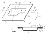
- FIG. 2A is a perspective view of the accommodation plate of FIG. 1, and FIG. 2B is a schematic cross-sectional view taken along line 2B-2B of FIG. 2A.
- FIG. 3A is a perspective view showing a schematic cross section taken along line 3-3 of FIG. 2A
- FIG. 3B is a cross sectional view taken along line 3-3 of FIG. 2A.
- 4A is a perspective view of the core layer
- FIG. 4B is a sectional view taken along line 4B-4B in FIG. 4A
- FIG. 4C is a line 4C-4C in FIG. 4A. View along the line.
- FIG. 4A is a perspective view of the core layer
- FIG. 4B is a sectional view taken along line 4B-4B in FIG. 4A
- FIG. 4C is a line 4C-4C in FIG. 4A. View along the line.
- FIG. 4A is a perspective view of the core layer
- FIG. 4B is a sectional view taken along line 4B-4
- FIG. 5A is a perspective view of a sheet material forming the core layer of FIG. 4A
- FIG. 5B is a perspective view showing a state of folding the sheet material of FIG. 5A
- FIG. FIG. 5C is a perspective view showing a state in which the sheet material of FIG.
- FIG. 6A is a schematic cross-sectional view of the core layer and the first and second skin layers prepared for manufacturing the accommodation plate of FIG. 2A
- FIG. 6B illustrates the heating step.
- Fig. 6(c) is a schematic diagram showing a laminated body placed in a mold
- Fig. 6(d) is a diagram illustrating a pressing step
- Fig. 6(e) is an intermediate body taken out from the mold.
- FIG. 6F is a schematic view showing the accommodation plate obtained through a post-processing step.
- FIG. 7A is a perspective view of a sheet material forming a core layer of a modified example
- FIG. 7B is a perspective view showing a state in which the sheet material of FIG. 7A is being folded
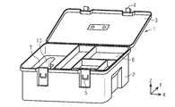
- the hollow structure of the present embodiment is a storage plate 7 provided inside a tool box 1 for storing tools.
- the tool box 1 includes a main body 2 that is a rectangular parallelepiped box, and a lid 3 that is rotatably attached to the main body 2.
- the lid 3 covers the opening of the main body 2.
- the lid part 3 can be displaced between a closed position where the opening of the body part 2 is closed by the lid part 3 and an open position where the opening of the body part 2 is opened. ..
- the lid portion 3 has a first engaging portion 4, and the main body portion 2 has a second engaging portion 5 that engages with the first engaging portion 4.
- the lid portion 3 is held in the closed position by the engagement of the first engaging portion 4 with the second engaging portion 5.
- the surface on which the second engaging portion 5 of the main body portion 2 is arranged is the front surface, and the direction in which the main body portion 2 is opened in the use state is the upper side. Further, with respect to the case where the front surface of the main body portion 2 is viewed from the front, the directions of up (Z-axis direction), down, left, right (X-axis direction), front, and rear (Y-axis direction) are defined.
- the X axis, the Y axis, and the Z axis are directional axes that are orthogonal to each other.
- a plurality of storage trays 6 are stored on the right side of the main body 2. These storage trays 6 are stacked in a plurality of stages in the vertical direction of the main body 2.
- the main body 2 has a peripheral wall and a plurality of support protrusions (not shown) protruding from the peripheral wall into the main body 2.
- Each accommodation tray 6 is placed in a positioned state on the plurality of support protrusions of the main body 2.
- the inside of each storage tray 6 is partitioned into a plurality of compartments. Tools such as wrenches, spanners, drivers, or nippers, or parts such as cables or nails can be sorted and housed in these compartments.
- a storage plate 7 is stored in the main body 2 on the left side of the storage tray 6.
- the accommodation plate 7 is placed in a positioned state on a plurality of support protrusions (not shown).
- the accommodating plate 7 has a recess 10 for stably accommodating a tool that is irregularly shaped and relatively bulky, such as an electric drill.
- the storage plate 7 of this embodiment is used to store an electric drill.
- the accommodation plate 7 has a plate-shaped hollow portion 16 and a dense portion 20 a that defines the recess 10.
- the hollow portion 16 has a first surface 7a which is an upper surface and a second surface 7b which is a lower surface.
- the dense portion 20a is a projecting portion that is located substantially in the center of the accommodation plate 7 and projects downward from the second surface 7b.
- the recess 10 opens on the first surface 7a.
- the shape of the recess 10 corresponds to the shape of an object to be stored, for example, an electric drill. When the electric drill is housed in the recess 10, the electric drill is held in a stable state.
- the dense portion 20a has a peripheral wall 11 extending from the opening of the recess 10, a bottom wall 12 that closes the protruding end (lower end) of the peripheral wall 11, and a curved portion 15 that connects the peripheral wall 11 and the bottom wall 12 smoothly.
- the area of the bottom wall 12 is smaller than the opening area of the recess 10.
- the peripheral wall 11 is inclined with respect to the first surface 7a and the second surface 7b so that the peripheral wall 11 is tapered toward the bottom wall 12.
- the accommodating plate 7 includes, for example, at least a recess for accommodating a drill blade for replacing the electric drill and a hole for gripping the accommodating plate 7. You may have one.
- the first and second surfaces 7a and 7b may be flat surfaces or curved surfaces, or may have an uneven pattern.
- the outer shape of the accommodation plate 7 of this embodiment is, for example, a substantially rectangular shape of about 25 cm ⁇ about 30 cm, and the thickness of the hollow portion 16 is about 2 cm.
- the depth of the recess 10 is, for example, about 4 cm.
- the recess 10 has a depth equal to or larger than the thickness of the accommodation plate 7, and the dense portion 20 a has a protruding length equal to or greater than the thickness of the accommodation plate 7.
- the depth of the recess 10 or the protruding length of the dense portion 20a is, for example, 1.5 to 4 times, preferably 2 to 4 times, preferably 2 to 3 times the thickness of the hollow portion 16. Is more preferable.
- the bottom wall 12 of the recess 10 is located below the second surface 7b of the accommodating plate 7, that is, at a position separated in the thickness direction of the accommodating plate 7 (direction along the Z axis).
- the first surface 7a, the second surface 7b, and the bottom wall 12 are arranged in this order along the thickness direction of the accommodation plate 7.
- the peripheral wall 11 has an inner surface 11a and an outer surface 11b.
- the accommodation plate 7 has a curved surface 13 that smoothly connects the first surface 7a and the inner surface 11a between the first surface 7a and the inner surface 11a.
- the curved surface 13 is an opening edge of the recess 10.
- the accommodation plate 7 has a curved surface 14 between the second surface 7b and the outer surface 11b, which smoothly connects the second surface 7b and the outer surface 11b.
- the radius of curvature of the curved surface 13 is equal to or larger than the radius of curvature of the curved surface 14.
- the radius of curvature of the curved portion 15 is larger than the radius of curvature of the curved surface 13.
- the accommodation plate 7 has an end surface 7c that extends around the entire outer edge.
- the end surface 7c is inclined with respect to the first surface 7a and the second surface 7b so that the end surface 7c is tapered toward the second surface 7b.
- the inclination angle ⁇ of the end surface 7c with respect to the plane including the second surface 7b is preferably 70° or more, more preferably 80° or more, and 85° or more. It is more preferable that there is. As the inclination angle ⁇ approaches 90°, the accommodation plate 7 can be stably placed on the support projection of the main body 2.
- the accommodation plate 7 has a curved surface 43 that smoothly connects the second surface 7b and the end surface 7c between the second surface 7b and the end surface 7c.
- the radius of curvature of the curved surface 43 is, for example, about 1 to 5 mm.
- the hollow portion 16 is a hollow plate in which a plurality of cells S are arranged.
- the hollow portion 16 includes a plate-shaped core layer 20, and first and second skin layers 30 and 40, which are sheets that are respectively thinner than the core layer 20 and are bonded to both surfaces of the core layer 20.
- the core layer 20 is shown in FIG.
- the core layer 20 is formed by forming a sheet material (first sheet material 100 described later) made of a thermoplastic resin into a predetermined shape and then folding the formed sheet material.
- the thickness of this sheet material is, for example, about 0.3 mm to 1.0 mm, and is about 0.5 mm in this embodiment.
- the core layer 20 includes a first wall 21, a second wall 22, and a plurality of partition walls 23 extending between the first wall 21 and the second wall 22.
- the first wall 21, the second wall 22, and the plurality of partition walls 23 partition the plurality of hexagonal prism-shaped cells S.
- the first wall 21 and the second wall 22 actually include a part having a one-layer structure and a part having a two-layer structure.
- the first wall 21 and the second wall 22 are illustrated as a single-layer structure for simplification.
- the plurality of cells S include a plurality of first cells S1 and a plurality of second cells S2.
- the first wall 21 that partitions each first cell S1 has a two-layer structure. The two layers forming the first wall 21 are joined to each other. An opening (not shown) is formed in the first wall 21 having a two-layer structure due to thermal shrinkage of the thermoplastic resin when molding the core layer 20.
- the 2nd wall 22 which divides each 1st cell S1 has 1 layer structure.
- the first wall 21 partitioning each second cell S2 has a one-layer structure.
- the second wall 22 that defines the second cell S2 has a two-layer structure.
- the two layers forming the second wall 22 are joined to each other.
- An opening (not shown) is formed in the second wall 22 having a two-layer structure due to thermal shrinkage of the thermoplastic resin when molding the core layer 20.
- the partition wall 23 located between the adjacent first cells S1 and the partition wall 23 located between the adjacent second cells S2 are , Both have a two-layer structure.
- the two layers forming the partition wall 23 have portions that are not thermally welded to each other in the center of the core layer 20 in the thickness direction. Therefore, the plurality of cells S in the core layer 20 can communicate with each other through the two layers forming the partition wall 23.
- the plurality of first cells S1 arranged along the X-axis form a first cell row.
- the plurality of second cells S2 arranged along the X axis form a second cell row.
- the first cell rows and the second cell rows are arranged alternately along the Y axis.
- the core layer 20 including the plurality of first cells S1 and the plurality of second cells S2 has a honeycomb structure as a whole.
- the first skin layer 30 includes a first inner layer 31 and a first design layer 32.
- the first inner layer 31 is arranged between the first design layer 32 and the core layer 20.
- the outer surface of the first design layer 32 (the surface opposite to the first inner layer 31) defines the first surface 7 a of the housing plate 7.
- the first inner layer 31 is joined to the core layer 20 via an adhesive layer not shown, and the first design layer 32 is joined to the first inner layer 31 via an adhesive layer not shown.
- the second skin layer 40 includes a second inner layer 41 and a second design layer 42.
- the second inner layer 41 is disposed between the second design layer 42 and the core layer 20.
- the outer surface of the second design layer 42 (the surface opposite to the second inner layer 41) defines the second surface 7b of the housing plate 7.
- the second inner layer 41 is bonded to the core layer 20 via an adhesive layer not shown, and the second design layer 42 is bonded to the second inner layer 41 via an adhesive layer not shown.
- the core layer 20, the first inner layer 31, and the second inner layer 41 are made of thermoplastic resin.
- the thermoplastic resin forming the core layer 20 may be any conventionally known thermoplastic resin. Examples of thermoplastic resins are polypropylene, polyamide, polyethylene, acrylonitrile-butadiene-styrene copolymer, acrylic, polybutylene terephthalate.
- the core layer 20 of this embodiment is made of polypropylene.
- the thermoplastic resin forming the first inner layer 31 and the second inner layer 41 may be any conventionally known thermoplastic resin.
- the first inner layer 31 and the second inner layer 41 of the present embodiment are made of the same polypropylene as the core layer 20.
- the resin forming the core layer 20 and the inner layers 31 and 41 is preferably such that the resin fluidity (MFR) of the inner layers 31 and 41 is smaller than the resin fluidity (melt mass flow rate: MFR) of the core layer 20.
- the thickness of the first inner layer 31 and the second inner layer 41 is, for example, about 0.3 mm to 1.0 mm.
- the thickness of the first inner layer 31 and the second inner layer 41 of this embodiment is about 0.5 mm.
- the design layers 32 and 42 impart design characteristics to the outer surface of the housing plate 7.
- the material of the design layers 32 and 42 is selected from, for example, conventionally known synthetic resin, synthetic leather, synthetic fiber, metal, natural leather, natural fiber, carbon fiber, or foam material.
- the design layers 32 and 42 may be non-woven fabric, woven fabric, knitted fabric, synthetic resin sheet (for example, smooth stretched sheet obtained by stretching synthetic resin), or metal sheet. Further, the design layers 32 and 42 may be printed with patterns or characters, or may include fibers of different colors.
- the design layers 32 and 42 of this embodiment are non-woven polypropylene sheets.
- the thickness of the design layers 32 and 42 is, for example, about 0.3 mm to 1.0 mm.
- the thickness of the design layers 32 and 42 of this embodiment is about 0.5 mm.
- the adhesive layer that joins the core layer 20 and the inner layers 31 and 41 is made of a resin that is compatible with the polypropylene that constitutes the inner layers 31 and 41.
- the adhesive layer that joins the first inner layer 31 and the first design layer 32 and the adhesive layer that joins the second inner layer 41 and the second design layer 42 are polypropylenes that form the inner layers 31 and 41. It is composed of a resin that is compatible with.
- the dense portion 20a is thinner than the hollow portion 16.
- the dense portion 20a is a portion obtained by deforming the core layer 20 (partitioning wall 23, the first wall 21 and the second wall 22) and the skin layers 30, 40 (inner layers 31, 41) to the extent that the shape of the cells S cannot be identified. That is, the thermoplastic resin, which is one of these materials, is an integrated part after melting. The cells S are crushed in the dense portion 20a, and there is almost no gap inside. That is, the dense portion 20 a has a lower porosity than the hollow portion 16. When the porosity of the resin mass having no gap inside is 0%, the porosity of the hollow portion 16 is about 80%.
- the porosity of the dense portion 20a is, for example, 1 to 15%, preferably 1 to 10%, more preferably 1 to 5%.
- the dense portion 20a includes a region 20A, a region 20B and a region 20C.
- the area 20A is a portion corresponding to the bottom wall 12
- the area 20C is a portion located between the first surface 7a and the second surface 7b in the thickness direction Z
- the area 20B is the area 20A of the peripheral wall 11 and the area. It is a portion located between 20B and 20B.
- the area 20A is a portion obtained by crushing and compressing the core layer 20 in the direction along the Z axis.
- the bent partition wall 23 and the resin pool (lump of resin) are observed. Specifically, a resin pool is observed in a portion where the partition wall 23 is compressed, and a slight space is observed in a portion where the partition wall 23 was not present. Therefore, when the cross section of the region 20A is enlarged and observed, the resin pools are distributed in a mesh shape. Further, in the region 20A, the resin pools are concentrated in a region closer to the center than the outer edge of the bottom wall 12. In the vicinity of the outer edge of the region 20A, the compressed partition walls 23 are more distributed than in the vicinity of the center.
- the width (maximum length) of each space slightly left in the region 20A is smaller than or substantially the same as the width (maximum length) of each resin pool.
- the thickness of the region 20A is greater than or substantially the same as the total thickness of the first wall 21, the second wall 22, and the skin layers 30 and 40 in the hollow portion 16.
- the thickness of the first sheet material 100 is about 0.5 mm
- the thickness of the first inner layer 31 and the second inner layer 41 is about 0.5 mm
- the thickness of the design layers 32 and 42 is about 0.5 mm
- the thickness of the bottom wall 12 is greater than or about the same as about 3.5 mm.
- the region 20B and the region 20C become thinner than the original core layer 20 when the core layer 20 is deformed so as to be stretched along the Z axis at the time of formation.
- the regions 20B and 20C are thinner than the region 20A.
- the peripheral wall 11 When the peripheral wall 11 is formed, the inner layers 31 and 41 are extended along with the core layer 20 along the Z axis. Therefore, the thickness of the peripheral wall 11 is thinner than the thickness of the bottom wall 12.
- the resin amount per unit volume in the peripheral wall 11 is smaller than the resin amount per unit volume in the bottom wall 12.
- the core layer 20 is melted and integrated with the inner layers 31, 41, whereas in the region 20C, the core layer 20 is melted only with the first inner layer 31. It is integrated. Therefore, the thickness of the region 20C is smaller than the thickness of the region 20B.
- the regions inside the curved surfaces 13 and 14 in the hollow portion 16 are referred to as regions 13A and 14A, respectively.
- the regions 13A and 14A have a resin reservoir and a folded partition wall 23.
- the region 14A has a lower porosity than the region 13A. Furthermore, the porosity of the curved portion 15 is lower than the porosity of the region 14A.
- the accommodation plate 7 has a dense portion 20b in which the core layer 20 is crushed, on the entire outer periphery thereof.
- the dense portion 20b has a thickness smaller than that of the hollow portion 16.
- the dense portion 20b is a portion obtained by compressing the core layer 20, the first inner layer 31, and the second inner layer 41 in the thickness direction and deforming the shape of the cell S to the extent that the shape of the cell S cannot be identified, like the recess 10. This is a part in which the thermoplastic resin, which is the material of, is integrated. In the dense portion 20b, the cells S are crushed and there is almost no gap inside.
- the entire outer edge of the second skin layer 40 is bent toward the dense portion 20b, whereas the outer edge of the first skin layer 30 is not bent.
- the outer edge of the first skin layer 30 and the outer edge of the second skin layer 40 are butted against each other with the dense portion 20b interposed therebetween.
- the outer edge of the first inner layer 31 and the outer edge of the second inner layer 41 are integrated with the dense portion 20b.
- the skin layer 40 has an end surface 44 that laterally covers the core layer 20 between the curved surface 43 and the outer edge. That is, the end surface 7 c of the accommodation plate 7 includes the outer edge of the first skin layer 30, the dense portion 20 b of the core layer 20, and the end surface 44 of the second skin layer 40.
- the accommodating plate 7 has a hollow portion 16 including a plurality of cells S, and a recess 10 (dense portion 20a) for accommodating the electric drill.
- the recess 10 has a shape that follows the outer shape of the electric drill and has a depth of about 4 cm. When the electric drill is housed in the recess 10, the electric drill is stably held in the recess 10 without rattling.
- the accommodating plate 7 has an end surface 44 which is the bent outer edge of the second skin layer 40 on the entire outer edge thereof, and the end surface 44 is a steep slope with respect to the first and second surfaces 7a and 7b. Therefore, the accommodation plate 7 is stably supported by the support protrusion.
- the dense portion 20a is thinner than the hollow portion 16 and there is almost no gap inside. That is, the peripheral wall 11, the bottom wall 12, and the curved portion 15 do not have a hollow structure. Therefore, the dense portion 20a has strength enough to withstand impact. Therefore, even if some impact is applied to the dense portion 20a, it is unlikely to be affected by the impact. For example, even if the tools stored in the tool box 1 hit the dense portion 20a, they are not easily affected by the impact. On the other hand, when an impact is applied to the thin outer wall of the hollow structure, there is a risk that the outer wall will have holes.
- the bottom wall 12 is located below the second surface 7b. Therefore, another tool housed in the space below the housing plate 7 in the tool box 1 may hit the bottom wall 12. Since the bottom wall 12 is not the hollow structure but the dense portion 20a, the bottom wall 12 is not easily affected by the impact when it comes into contact. Even if the thickness of the bottom wall 12 is somewhat uneven, the surface thereof (the surface that defines the recess 10 and the back surface on the opposite side) is gentle. Therefore, it is difficult for an object to be caught in the dense portion 20a.
- the method for manufacturing the accommodation plate 7 includes a core layer forming step, a heating step, a joining step, a pressing step, and a post-processing step.
- the core layer forming step the core layer 20 is formed from one sheet material.
- the heating step the core layer 20 and the skin layers 30 and 40 which are the heating targets are heated.
- the joining step the skin layers 30 and 40 are joined to both surfaces of the core layer 20 to obtain a hollow plate material.
- the pressing step the hollow plate material is press-molded to obtain the intermediate body 60 having the recess 10.
- the post-processing step the end face of the intermediate body 60 is arranged and the accommodation plate 7 is obtained. In this embodiment, the joining process is performed simultaneously with the pressing process.
- the core layer molding process will be described.
- the core layer forming step the first sheet material 100 shown in FIG. 5A is folded.
- the first sheet material 100 is made of a thermoplastic resin and is formed into a predetermined shape as shown in FIG. 5(a).
- the first sheet material 100 has a band-shaped flat area 110 and a swollen area 120, and the flat area 110 and the swollen area 120 are alternately arranged along the longitudinal direction (X axis) of the first sheet material 100. Lined up.
- Each of the bulging regions 120 is formed integrally with the flat region 110, a flat portion that is flush with the flat region 110, one first bulging portion 121 that bulges along the Z axis from the flat portion, and the first bulging portion 121. And a plurality of second bulges 122.
- the first bulging portion 121 has a first bulging surface parallel to the plane portion and two connecting surfaces extending between the plane portion and the first bulging surface.
- the first bulging surface extends over the entire bulging region 120 in the extending direction (the direction along the Y axis).
- the angle formed by the first bulging surface and the connecting surface is preferably 90 degrees.
- the first bulging portion 121 has a groove shape that opens downward in FIG.
- the width (length along the X axis) of the first bulging portion 121 is equal to the width (length along the X axis) of the flat area 110, and the bulging height (Z) of the first bulging portion 121.
- the length is twice the length along the axis).
- Each second bulging portion 122 has a second bulging surface extending from the first bulging surface, a trapezoidal end surface obtained by bisecting a regular hexagon with the longest diagonal, and two second bulging surfaces extending from the first bulging surface to the flat surface portion. And an inclined surface.
- the plurality of second bulging portions 122 extend along the X axis, are orthogonal to the first bulging portion 121, and are arranged along the Y axis.
- the bulge height (the length along the Z axis) of the second bulge portion 122 is equal to the bulge height (the length along the Z axis) of the first bulge portion 121.
- the interval between the second bulging portions 122 arranged along the Y axis is equal to the width of the second bulging surface (the length along the Y axis).
- the first bulging portion 121 and the second bulging portion 122 are formed by bulging a part of the sheet by utilizing the plasticity of the sheet. That is, the first sheet material 100 is formed from one sheet by a known forming method such as a vacuum forming method or a vacuum pressure forming method.
- the boundary line P is the boundary between the flat region 110 and the bulging region 120
- the boundary line Q is the first bulging surface of the first bulging portion 121. It is the boundary with the connection surface.
- the core layer 20 is formed by folding the first sheet material 100 along the boundary lines P and Q. Specifically, the first sheet material 100 is valley-folded at the boundary line P and mountain-folded at the boundary line Q. Then, as shown in FIGS. 5B and 5C, the first bulging surface of the first bulging portion 121 and the connecting surface are overlapped with each other along the Z axis, and the end surface of the second bulging portion 122 is The plane area 110 is overlapped along the Z axis. As a result, one prismatic partition 130 extending along the Y axis is formed in each bulged region 120. The partition plate 130 is continuously formed along the X axis to form the hollow plate-shaped core layer 20.
- the first wall 21 of the core layer 20 has a two-layer structure in which the first bulging surface and the connecting surface of the first bulging portion 121 overlap, and the second wall 22 of the core layer 20 has the second bulging portion. It has a two-layer structure in which the end face 122 and the planar region 110 overlap. As shown in FIG. 5C, the portion of the two-layer structure of the first and second walls 21, 22 is the overlapping portion 131.
- the hexagonal column-shaped region defined by the two second bulging portions 122 arranged along the X axis in each bulging region 120 becomes the second cell S2, and the flat portion of the bulging region 120 and the second bulging portion 122 are formed.
- the hexagonal column-shaped region defined by the inclined surface is the first cell S1. That is, the second bulge surface and the inclined surface serve as the partition wall 23 of the second cell S2, and the inclined surface and the flat surface portion serve as the partition wall 23 of the first cell S1.
- the two second bulging surfaces that overlap along the X axis and the two flat surface portions that overlap along the X axis form a partition wall 23 having a two-layer structure.
- the core layer 20 and the skin layers 30 and 40 manufactured in the core layer forming step are cut so that the outer shape is slightly larger than the housing plate 7.
- the core layer 20 and the skin layers 30 and 40 are, for example, rectangular, which is larger than the size of the housing plate 7 by about 50 mm in the longitudinal direction and the lateral direction. 6(a) to 6(f), the details of each component including the hollow structure of the core layer 20 are omitted.
- the first skin layer 30 is a sheet in which the first design layer 32 is laminated on the first inner layer 31 in advance.
- the first inner layer 31 and the first design layer 32 are joined together via an adhesive layer made of a resin compatible with polypropylene, which is the material of the first inner layer 31.
- the second skin layer 40 is a sheet in which the second design layer 42 is previously laminated on the second inner layer 41.
- the second inner layer 41 and the second design layer 42 are joined together via an adhesive layer made of a resin compatible with polypropylene, which is the material of the second inner layer 41.
- the surface of the first inner layer 31 opposite to the first design layer 32 is coated with an adhesive layer made of a resin compatible with polypropylene, which is the material of the first inner layer 31.
- the surface of the second inner layer 41 opposite to the second design layer 42 is coated with an adhesive layer made of a resin compatible with polypropylene, which is the material of the second inner layer 41.
- the core layer 20 is put in a heating furnace 71 set to a specified temperature and held for a specified time.
- the skin layers 30 and 40 are put in a heating furnace 72 set to a specified temperature and held for a specified time.
- the temperature in the heating furnace 71 is set to a temperature at which the thermoplastic resin (polypropylene in this embodiment) forming the core layer 20 melts.
- the temperature in the heating furnace 71 is set to such an extent that the thermoplastic resin (polypropylene in this embodiment) forming the skin layers 30 and 40 melts.
- the surface temperature of the core layer 20 is adjusted in the heating furnace 71 so that it varies depending on the site.
- the surface temperatures of the skin layers 30 and 40 are adjusted to be different depending on the site.
- the portion of the core layer 20 where the temperature is desired to be relatively low may be covered with the shielding material 73.
- the shielding material 73 is illustrated only in the heating furnace 71 in FIG. 6B, the shielding material 73 that partially covers the skin layers 30 and 40 may be arranged in the heating furnace 72.
- the shielding material 73 may not be arranged in the heating furnace 72, and the entire skin layers 30 and 40 may be heated uniformly.
- the shielding material 73 may have a plurality of fine through holes.
- the heat shielding effect can be further enhanced by disposing a shielding material having no through hole.
- the shielding material 73 covers a portion where the thickness of the hollow plate material is not thinned in the later pressing step, that is, a portion where the core layer 20 and the skin layers 30 and 40 are not melted.
- the recess 10 is formed in the central portion of the hollow plate material by press molding, and at the same time the compression portion 61 is formed on the outer edge of the hollow plate material.
- the shielding material 73 is arranged in the portion excluding the compression portion 61 and the recess 10.
- the surface temperature of the portion of the core layer 20 where the crushed width is small or hardly crushed is relatively low, and the surface temperature of the portion where the crushed width of the core layer 20 is large is relatively set. Higher.
- the surface temperature of the portion of the core layer 20 where the crushed width is large is approximately the same as the heating temperature in the heating furnace 71.
- the method of adjusting the surface temperature of the skin layers 30 and 40 is the same as that of the core layer 20.
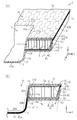
- the die used in the pressing step (and the joining step) includes a first die 81 and a second die 82.
- the first and second molds 81 and 82 of the present embodiment are used at room temperature without being entirely heated.
- the second mold 82 has a second flat surface 82c that contacts the first mold 81, a first step surface 82a that is recessed from the second flat surface 82c, and a second step surface that is further recessed from the first step surface 82a. 82b.
- the second mold 82 further has an inclined molding surface 82d extending between the second flat surface 82c and the outer edge of the first step surface 82a.
- the inclined molding surface 82d is inclined with respect to the second flat surface 82c and the first step surface 82a.
- the first step surface 82a and the inclined molding surface 82d are smoothly connected via the curved surface 82e.
- the inclined molding surface 82d, the curved surface 82e, and the first step surface 82a are concave portions for forming the hollow portion 16 of the accommodation plate 7, and have a rectangular outer shape.
- the inclined molding surface 82d is a surface for forming the end surface 7c (end surface 44) of the accommodation plate 7.
- the curved surface 82e is a surface for forming the curved surface 43.
- the length of the inclined forming surface 82d in the longitudinal direction is substantially the same as the length of the accommodating plate 7 in the longitudinal direction, and the length of the inclined forming surface 82d in the lateral direction is substantially the same as the length of the accommodating plate 7 in the lateral direction. It is the same.
- the depth of the first step surface 82a is slightly shallower than the thickness of the accommodation plate 7.
- the second step surface 82b is a recess for forming the dense portion 20a (recess 10) and has an outer edge along the outer shape of the electric drill.
- the first step surface 82a and the second step surface 82b are smoothly connected via the curved surfaces 82f and 82g.
- the curved surface 82f is a surface for molding the curved surface 14
- the curved surface 82g is a surface for molding the curved portion 15.
- the depth of the second step surface 82b with respect to the first step surface 82a is about 2 cm.
- the outer shapes and the depths of the first and second step surfaces 82a and 82b may be set in consideration of the thermal contraction of the core layer 20 and the skin layers 30 and 40.
- the first mold 81 has a first flat surface 81d that abuts the second flat surface 82c during mold clamping, step surfaces 81a and 81b that are recessed from the first flat surface 81d, and a projecting surface that projects from the first flat surface 81d. 81c.
- the outer step surface 81b has a rectangular outer shape, and the inner step surface 81a is located inside the outer step surface 81b.
- An intersecting surface 81e orthogonal to the outer step surface 81b and the first flat surface 81d extends between the outer step surface 81b and the first flat surface 81d.
- a protruding inclined surface 81f extends between the inner step surface 81a and the protruding surface 81c.
- the protruding inclined surface 81f and the inner stepped surface 81a are smoothly connected by the curved surface 81g.
- the protruding inclined surface 81f and the protruding surface 81c are smoothly connected by the curved surface 81
- the step surfaces 81a and 81b are flush with each other, and the depth thereof is almost the same as the thickness of the compression portion 61 of the intermediate body 60 described later.
- the inner step surface 81a is a surface for molding the first surface 7a
- the outer step surface 81b and the intersecting surface 81e are portions for molding the compression portion 61 of the intermediate body 60.
- the protruding inclined surface 81f is a surface for molding the region 20B and the region 20C.
- the curved surface 81g is a surface for molding the curved surface 13.
- the curved surface 81h is a surface for molding the curved portion 15.
- the inner stepped surface 81a faces the second stepped surface 82b and the outer stepped surface 81b faces the second flat surface 82c when the mold is clamped.
- the protruding surface 81c is a surface for molding the region 20A, and the outer shape thereof is along the outer shape of the second step surface 82b (electric drill).
- the protruding surface 81c projects about 4 cm from the inner stepped surface 81a.
- the heated second skin layer 40, the core layer 20, and the first skin layer 30 are laminated on the second mold 82 in this order from the bottom.
- This is called a laminated body 70.
- the laminated body 70 is placed with the outer edge thereof on the second flat surface 82c so as to cover the step surfaces 82a and 82b.
- the laminated body 70 is positioned with respect to the first and second molds 81 and 82 according to the surface temperature adjusted by using the shielding material 73. Specifically, the portion where the surface temperature of the laminated body 70 is low is arranged between the inner step surface 81a and the first step surface 82a. Further, the central portion of the laminated body 70 where the surface temperature is high is arranged between the protruding surface 81c and the second step surface 82b. Further, the outer edge portion of the laminate 70 having a high surface temperature is aligned with the position of the outer step surface 81b of the first mold 81.
- the laminated body 70 is based on the height of the molding space defined between the first die 81 and the second die 82 when the die is clamped, that is, the distance between the first die 81 and the second die 82. Be positioned.
- the molding space includes a non-compressed space between the first step surface 82a and the inner step surface 81a, an inner compressed space between the second step surface 82b and the protruding surface 81c, a first flat surface 81d and an outer step surface. 81b and the outer compression space between 81b.
- the height of the uncompressed space is about 2 cm
- the height of the inner compressed space and the outer compressed space is relatively lower than that of the uncompressed space, for example, about 3.5 mm.
- a region arranged in the non-compressed space is called an uncompressed region 75
- a region arranged in the inner compressed space is called an inner compressed region 76
- a region arranged in the outer compressed space is called an outer compressed region 77.
- the temperature of the laminate 70 (core layer 20 and skin layers 30, 40) is adjusted according to the height of the molding space. That is, the temperature of the non-compression region 75 is lower than the temperatures of the inner compression region 76 and the outer compression region 77.
- the adhesive layers coated on the heated skin layers 30 and 40 are in a state where a part of the thermoplastic resin is melted by heat. Therefore, the core layer 20 and the skin layers 30 and 40 positioned on the second mold 82 are provisionally joined via these adhesive layers.
- the pressing process and the joining process are performed by moving the first mold 81 toward the second mold 82.
- the first mold 81 and the second mold 82 have a plurality of suction holes (not shown).
- the laminated body 70 (the core layer 20 and the skin layers 30 and 40 temporarily joined to each other) is sucked through the suction holes. Thereby, the laminated body 70 is brought into close contact with the first and second molds 81 and 82.
- the pressure during pressing and the pressing time may be set appropriately.
- the heated core layer 20 and the skin layers 30 and 40 are also partially melted. Therefore, the first and second skin layers 30 and 40 are bonded to both surfaces of the core layer 20 by mold clamping.
- openings are formed in the first and second walls 21 and 22 having the two-layer structure.
- the two layers constituting one partition wall 23 are thermally welded to each other at both ends in the thickness direction of the core layer 20, but portions not thermally welded to each other remain in the vicinity of the center in the thickness direction.
- the air between the core layer 20 and the skin layers 30 and 40 easily escapes through the openings in the first and second walls 21 and 22 and the gaps in the core layer 20. Therefore, generation of unintended air accumulation is suppressed, and the joint strength between the core layer 20 and the skin layers 30 and 40 is improved.
- the laminated body 70 becomes the intermediate body 60 molded into the shape of the molding space.
- the core layer 20 arranged in the outer compression space is heat-melted to become a solid state in which the first wall 21, the second wall 22 and the partition wall 23 are integrated. Further, the melted core layer 20 and the melted inner layers 31, 41 are integrated with each other, so that the compression portion 61 of the intermediate body 60 is formed. Since the design layers 32 and 42 which are not thermoplastic resins do not melt, the texture and pattern of the outer surface are maintained.
- the core layer 20 and the inner layers 31 and 41 are thermally melted and integrated, so that the dense portion 20a (recess 10) is formed. It is formed.
- the radius of curvature of the curved portion 15 is larger than the radius of curvature of the curved surface 13, and the radius of curvature of the curved surface 13 is the same as or larger than the radius of curvature of the curved surface 14. Therefore, when the inner compression region 76 is extended along the second mold 82, the inner compression region 76 (dense portion 20a) does not have unintended holes.
- the uncompressed space that is, the core layer 20 (the uncompressed region 75) arranged between the inner step surface 81a and the first step surface 82a is hardly compressed.
- heat is less likely to be transferred to the partition wall 23, and thus the partition wall 23 is less likely to be deformed.
- the temperature is different between the inner compression area 76 and the non-compression area 75. Due to this temperature difference, a difference occurs in the molten state of the thermoplastic resin, so that the radius of curvature of the curved surfaces 13 and 14 becomes smaller.
- the bending strength of the accommodation plate 7 is maintained by maintaining the honeycomb structure of the core layer 20 around the recess 10 as well.
- the partition wall 23 that partitions the cells S in the first and second rows inside is bent at both ends along the curved surfaces 13 and 14. Therefore, the bent partition wall 23 does not cause the curved surfaces 13 and 14 to partially project.
- the cells S in the first row on the inner side are arranged along the opening edge of the recess 10, that is, the curved surface 13, and have the partially compressed first wall 21.
- the cells S in the inner first row include first cells S1 and second cells S2 arranged alternately along the curved surface 13.
- the first wall 21 of the first cell S1 has a double layer structure
- the first wall 21 of the second cell S2 includes a single layer structure.
- the first wall 21 having a single-layer structure is more easily stretched during press molding than the first wall 21 having a two-layer structure. Therefore, the opening edge of the recess 10 is not partially largely deformed.
- the first wall 21 of the cell S in the cell S in the inner first row which is located away from the corner 10a, has the corner 10a. It is stretched more than the first wall 21 of the cell S at. Also in this case, the unintentional deformation of the curved surface 13 is reduced by the extension of the first wall 21 having the one-layer structure.
- the cell S in the first inner column is compressed more than the cell S in the second inner column. Therefore, for example, as shown in FIG. 3B, when the partition wall 23 of the cell S in the first inner row has one bent portion, the partition wall 23 of the cell S in the second inner row has two bends. May have parts. At this time, the two bent portions may overlap each other.
- the uncompressed region 75 and the outer compressed region 77 have different temperatures, a difference occurs in the molten state of the thermoplastic resin between them. As a result, the radius of curvature of the curved surface 43 becomes smaller. Thereby, the inclination angle ⁇ of the end surface 7c (end surface 44) can be brought close to 90°. On the other hand, the first skin layer 30 is maintained in a flat state without being bent.
- a cell immediately inside the end surface 7c of the accommodation plate 7 (hereinafter, referred to as an outermost cell S)
- a cell S immediately inside the outermost cell S (hereinafter, referred to as a cell S in the outer second row) is compressed in the thickness direction Z, but a cell S inside the cell S in the outer second row, that is, a hollow
- the cell S of portion 16 is not compressed. Therefore, the partition wall 23 of the hollow portion 16 is neither bent nor bent. In this way, the bending strength of the accommodation plate 7 is maintained by maintaining the honeycomb structure of the core layer 20 even near the end surface 7c.
- the intermediate body 60 After the first mold 81 is separated from the second mold 82 to cool the intermediate body 60, the intermediate body 60 is taken out of the second mold 82 as shown in FIG.
- the intermediate body 60 obtained through the bonding step and the pressing step has the first and second skin layers 30 and 40 bonded to both surfaces of the core layer 20, respectively.
- the intermediate body 60 has a compression portion 61 extending over the entire circumference of the outer edge, and a recess 10 (dense portion 20a) formed in the center.
- the dense portion 20a and the compressed portion 61 have a thickness of about 3.5 mm, and the non-compressed region 75 has a thickness of about 2 cm.
- the compression portion 61 of the intermediate body 60 is cut off by a cutting jig (not shown) to obtain the accommodation plate 7.
- the cut surface of the cut intermediate body 60 that is, the end surface 7 c of the accommodating plate 7 has an edge of the skin layer 30 and an edge of the skin layer 40.
- the dense portion 20b of the core layer 20 is exposed between them.
- the end surface 7c includes the edge of the skin layer 30, the end surface 44 of the skin layer 40, and the dense portion 20b of the core layer 20.
- the cut surface of the intermediate body 60 is polished and painted to adjust the shape of the end surface 7c.
- polishing and painting need not be performed.
- the accommodation plate 7 is obtained through the above steps.
- the dense portion 20a (recess 10) of the housing plate 7 includes a portion where the core layer 20 and the skin layers 30 and 40 are melted and integrated. Specifically, the thermoplastic resin forming the core layer 20 and the thermoplastic resin forming the first inner layer 31 and the second inner layer 41 are integrated.
- the dense portion 20a includes a hollow cell, if a certain impact is applied to the dense portion 20a, the thin wall partitioning the cell S may be deformed.
- the dense portion 20a has a solid shape in which a thermoplastic resin is integrated. Therefore, even if some impact is applied to the dense portion 20a, the influence can be reduced. Therefore, the accommodation plate 7 has excellent impact strength.
- the core layer 20 in the dense portion 20a is deformed to the extent that the shape of the cell S cannot be identified by being crushed in the pressing process. As a result, there are almost no gaps inside the dense portion 20a. Therefore, the dense portion 20a has high strength against impact.
- the accommodating plate 7 is accommodated in the tool box 1, and the dense portion 20 a has a depth equal to or larger than the thickness of the hollow portion 16. Therefore, the tools stored under the storage plate 7 in the tool box 1 may collide with the dense portion 20a. Also in this case, since the solid dense portion 20a has excellent impact strength, the impact of collision can be suppressed.
- the opening edge of the recess 10 is the curved surface 13, and the peripheral wall 11 of the dense portion 20 a is inclined at a steep angle with respect to the hollow portion 16 and the bottom wall 12. Therefore, a large capacity of the recess 10 can be secured.
- the curved surface 43 of the accommodation plate 7 has a radius of curvature of about 5 to 10 mm, and the end surface 44 (end surface 7c) is a steep slope. Therefore, when the accommodation plate 7 is placed on the support protrusion of the tool box 1, the accommodation plate 7 can be stably supported by the support protrusion. Further, it is possible to suppress the accumulation of dust or dirt between the support protrusion and the accommodation plate 7.
- the cells S in the inner first row and the second row are compressed in the thickness direction, but the cells S outside thereof are not compressed. That is, the partition wall 23 of the hollow portion 16 is not bent or bent. Since the honeycomb structure of the core layer 20 is maintained even in the vicinity of the dense portion 20a, the bending strength of the accommodation plate 7 is maintained.
- the end surface 44 exposed at the end surface 7c of the accommodation plate 7 covers the core layer 20 from the side. Therefore, it is possible to prevent foreign matter, such as dust or dirt, from entering the plurality of cells S arranged in the core layer 20.
- the housing plate 7 is made of polypropylene. Polypropylene has a smaller specific gravity and is stronger than other general-purpose thermoplastic resins. Therefore, the accommodation plate 7 is lightweight and has excellent impact strength.
- the manufacturing process can be simplified by performing the joining process at the same time as the pressing process. Therefore, it is advantageous in terms of workability and cost.
- the non-compressed area 75 is covered with the shielding material 73 and heated. Therefore, the core layer 20 and the skin layers 30 and 40 can easily be partially made different in temperature.
- the surface temperature of the core layer 20 and the skin layers 30 and 40 are partially made different by installing the shielding material 73. Therefore, it is not necessary to heat the first and second molds 81 and 82 in the subsequent joining process and pressing process. Therefore, the dense portion 20a and the compression portion 61 can be formed by a single press molding. This simplifies the process, which is advantageous in terms of workability and cost.
- the first and second molds 81 and 82 used in the joining process and the pressing process have a height of the inner compression space of about 3.5 mm when the molds are clamped. Then, in the inner compression space, the inner compression region 76 that is heated to a relatively high temperature in the heating step is arranged. Therefore, the core layer 20 in the inner compression region 76 is crushed by press molding, and the core layer 20, the first inner layer 31, and the second inner layer 41 are integrated to reduce the thickness to about 3.5 mm. In this way, the dense portion 20a can be molded with good dimensional accuracy.
- the core layer 20 and the skin layers 30 and 40 are placed on the second mold 82 after being preheated in the heating step. At this time, the thermoplastic resin adhesive layers coated on the first and second skin layers 30 and 40 are melted by heat. Therefore, the first and second skin layers 30 and 40 are temporarily bonded to both surfaces of the core layer 20, respectively. Accordingly, the first and second skin layers 30 and 40 can be accurately positioned with respect to the core layer 20.
- the skin layer 30 that is heated in the heating step includes the first inner layer 31 and the first design layer 32 that are previously laminated to each other.
- the skin layer 40 is the second inner layer 41 and the second layer that are previously laminated to each other. And a design layer 42. Therefore, in the joining step, the first and second skin layers 30 and 40 may be positioned with respect to the core layer 20. That is, the work efficiency is improved as compared with the case where the inner layers 31, 41 and the design layers 32, 42 are separately positioned.
- the core layer 20 is heated in the heating furnace 71, and the first and second skin layers 30, 40 are heated in the heating furnace 72. Therefore, it is easy to adjust the temperature and manage the temperature between the core layer 20 and the skin layers 30 and 40. Also, each layer can be heated to a uniform temperature.
- the first and second molds 81 and 82 have a plurality of suction holes. By sucking the core layer 20 and the skin layers 30 and 40 through the suction holes, the core layer 20 and the skin layers 30 and 40 can be brought into close contact with the inside of the molds 81 and 82 and can be appropriately positioned. As a result, the displacement of the core layer 20 and the skin layers 30 and 40 can be suppressed. As a result, the accommodating plate 7 with high accuracy can be manufactured.
- the skin layer 30 may not have the design layer 32.
- the skin layer 40 may not have the design layer 42.
- the material of at least one of the first inner layer 31 and the second inner layer 41 does not have to be made of a thermoplastic resin, and for example, other conventionally known synthetic resin, synthetic leather, synthetic fiber, metal, natural leather, or natural fiber May be
- the sheet layers 31 and 41 which are not made of a thermoplastic resin are each coated with an adhesive layer made of a thermoplastic resin which is compatible with the thermoplastic resin which constitutes the core layer 20, and the core layers are interposed via these adhesive layers. It is good to join to 20.
- the dense portion 20a becomes a solid state in which the core layer 20 (thermoplastic resin) and the adhesive layers coated on the sheet layers 31 and 41 are integrated, and there is almost no gap inside. As a result, the dense portion 20a that is resistant to impact is formed.
- the skin layers 30 and 40 may have different configurations.
- the design layers 32 and 42 may be made of different materials or different forms, or the inner layers 31, 41 may be made of different materials or different forms.
- the accommodation plate 7 does not have to have either one of the skin layers 30 and 40.
- a thin steel plate may be joined between the skin layer 30 and the core layer 20 or between the skin layer 40 and the core layer 20 in order to increase the rigidity of the accommodation plate 7.
- the material of the steel plate include thin plates made of metal such as aluminum alloy, iron alloy, and copper alloy.
- the thickness of the steel sheet is preferably about 0.05 mm to 0.5 mm.
- the position of joining the steel plates is preferably provided in the non-compressed region 75 (a part other than the recess 10) in consideration of the ease of the pressing process, but is not particularly limited.
- the bending strength of the accommodation plate 7 can be improved by joining the steel plates from one edge of the accommodation plate 7 to the other edge thereof.
- the radius of curvature of the curved surfaces 13 and 14 can be reduced.
- the housing plate 7 has a hinge portion
- the hinge portion is reinforced and the bending strength is improved, and the radius of curvature at the hinge portion is increased. It can be made smaller.
- a plurality of metal rods may be pressed into the core layer 20, or a resin material such as urethane may be injected into the cells S of the core layer 20.
- the cross-sectional shape of the metal rod material to be press-fitted is not particularly limited, and may be, for example, H-steel or L-steel in addition to a rod material having a circular or groove-shaped cross-section. Further, by injecting an adhesive around the press-fitted metal rod, it is possible to further reinforce.
- At least one of the core layer 20 and the skin layers 30 and 40 is made of a material having a high tensile elastic modulus such as carbon fiber or glass fiber, or a reinforcing material such as talc. You may comprise with the thermoplastic resin containing.
- At least one of the core layer 20 and the skin layers 30 and 40 may be made of a thermoplastic resin to which various functional resins are added.
- flame retardancy can be increased by adding a flame retardant resin to a thermoplastic resin.
- the hollow structure is not limited to the housing plate 7 that houses the electric drill.
- the hollow structure may be used for a container or plate for accommodating other tools, or may be used for an automobile interior member or building material.
- the hollow structure can be applied to a luggage board forming a bottom surface of a luggage room provided at a rear portion of an automobile.
- the recessed portion (dense portion) of the luggage board is used to fix the luggage board to the vehicle body.
- the luggage board has a dense portion (projection portion) protruding downward at the end thereof, and the dense portion is fixed to the vehicle body by being inserted into a through hole provided in the vehicle body. R.
- the dense portion is used as a support protrusion for supporting or fixing the luggage board.
- the support protrusions are solid with thermoplastic resin integrated, they are excellent in impact strength and can stably support or fix the luggage board.
- a space for accommodating tools etc. is provided below the luggage board. In this case, even if the tool stored below collides with the support protrusion (dense portion), excellent impact strength can be exhibited against the impact and the like.
- the thickness of the core layer 20 and the skin layers 30 and 40 and the thickness of the first sheet material 100 can be arbitrarily changed.
- the accommodating plate 7 is open to at least one of the first and second surfaces 7a and 7b or the protrusion that protrudes from at least one of the first and second surfaces 7a and 7b, in addition to the recess 10 (the dense portion 20a). You may have a recessed part. Thereby, in the tool box 1, it is possible to avoid interference with the uneven shape above or below the accommodation plate 7 or to accommodate another object in the formed space. Further, the accommodation plate 7 may have a through hole. This through hole may be used as a handle for lifting the accommodation plate 7, for example.
- the position of the recess 10 (dense portion 20a) in the accommodation plate 7 may be changed, and for example, the recess (dense portion) may be arranged at the edge of the accommodation plate 7. Since the end edge of the accommodation plate 7 is likely to be impacted, the strength of the accommodation plate 7 against impact is improved by arranging a solid dense portion at that portion. Therefore, for example, even when the accommodation plate 7 is accidentally dropped, the deformation can be suppressed. Further, by making the edge solid, the cell S at the outermost edge can be sealed.
- the end surface 7c of the accommodation plate 7 may include the outer edges of the first and second skin layers 30 and 40 that are curved so as to approach each other, or the first curve that is curved so as to approach the outer edge of the flat second skin layer 40.
- the outer edge of the skin layer 30 may be included.
- the end surface 7c of the accommodation plate 7 may include a different member different from the second skin layer 40 instead of the end surface 44 of the second skin layer 40.
- the accommodation plate 7 may include a first member that seals the outermost cell S and a second member that covers the first member.
- the shape of the recess 10 (dense portion 20a) can be changed.
- the peripheral wall 11 may be a gentle slope.
- the shapes of the peripheral wall 11 and the curved surfaces 13 and 14 may be determined according to the shapes of the objects accommodated in the recess 10.
- the inclination angle ⁇ of the end surface 44 may be less than 70°. Further, the radius of curvature of the curved surface 43 is not limited to that of the above-described embodiment.
- the core layer 20 includes, for example, partition walls formed by bending a plurality of strip-shaped sheets at predetermined intervals, and first and second sheet layers respectively arranged on both sides of these strip-shaped sheets. You may.
- the second sheet material 200 which is a three-dimensional structure in which a plurality of protruding surfaces having trapezoidal cross sections are arranged, is folded along the boundaries R and T.
- the core layer 24, which is a honeycomb structure, may be formed by proceeding.
- the second sheet material 200 has a plurality of first bulging portions 210 and second bulging portions 220 that bulge in mutually opposite directions along the Z axis.
- the plurality of first and second bulges 210 and 220 extend along the X axis and are arranged side by side along the X axis.
- Each first bulge 210 has a first bulge 210a, two end faces 210c, and two connecting faces 210b.
- Each second bulging portion 220 has a second bulging surface 220a, two end surfaces 220c, and two connecting surfaces 220b.
- the second sheet material 200 is mountain-folded along the boundary line R and is valley-folded along the boundary line T.
- the two first bulging portions 210 arranged with the boundary line T sandwiched therebetween have their first bulging surfaces 210a in contact with each other to form a partition wall 27 having a two-layer structure.
- the connection surface 210b becomes the partition wall 27 having a one-layer structure.
- the two end surfaces 210c arranged along the X axis serve as the first wall 25.
- the connection surface 220b becomes the partition wall 27 having a one-layer structure.
- the two end faces 220c arranged along the X axis serve as the second wall 26.
- a hollow plate material is obtained by bonding the first and second skin layers 30 and 40 to both surfaces of the core layer 24 thus obtained.
- the shape of the cell S can be changed arbitrarily. For example, it may have a polygonal shape such as a quadrangular prism shape or an octagonal prism shape, a cylindrical shape, or a prefix cone shape. Further, the plurality of cells S may include cells having different shapes. A gap (space) may exist between adjacent cells.
- the core layer 20 may have a core layer having a predetermined uneven shape, and first and second sheet layers respectively bonded to both surfaces of this core layer.
- An example of the core layer having such a structure is disclosed in, for example, JP-A-2014-205341.
- the core layer 20 may be a plastic cardboard having a harmonica-shaped cross section.
- the heating temperature in the heating step constitutes the material of the thermoplastic resin forming the core layer 20, the material of the thermoplastic resin forming the skin layers 30, 40, or the adhesive layer coated on the skin layers 30, 40. It can be appropriately changed depending on the material of the thermoplastic resin.
- the core layer 20 and the skin layers 30 and 40 may be heated in the same heating furnace.
- the core layer 20 and the skin layers 30 and 40 may be heated not in the heating furnaces 71 and 72 but in an open environment.
- the core layer 20 and the skin layers 30 and 40 may be heated by a burner, an IH heater, or an infrared heater.
- the heating step in order to adjust the surface temperature of the core layer 20 and the skin layers 30 and 40 to be different depending on the site, a method other than the shielding by the shielding material 73 may be used.
- the core layer 20 and the skin layers 30 and 40 may be partially heated by a burner, an IH heater, or an infrared heater.
- the skin layers 30 and 40 may not be provided with a pre-coated adhesive layer, and an adhesive may be applied to the skin layers 30 and 40 at the time of joining.
- the core layer 20 and the skin layers 30 and 40 are bonded to each other with an adhesive to form a hollow plate material (bonding step), and then heated in a heating furnace (heating step), and then the heated hollow plate material. May be press-formed (pressing step).
- the heating target in this case is a hollow plate material.
- a sheet material having an uneven shape is folded to form a core layer, and an adhesive is applied to both sides of the core layer, and then the first and second skins are applied to both sides of the core layer.
- the layers may be adhered together.
- the core layer forming step and the joining step can be continuously performed on one production line, so that work efficiency is good.
- the skin layer to which the adhesive has been applied in advance may be supplied.
- the shape of the suction holes of the molds 81 and 82 is not particularly limited, and may be, for example, a slit-shaped suction groove.
- the molds 81 and 82 may not have suction holes.
- the joining process and the pressing process may be performed with the molds 81 and 82 heated.
- the mold used in the joining process and the pressing process may have a shape different from that of the molds 81 and 82.
- the second mold 82 may include a movable mold 83 for forming the curved surface 14.
- the movable die 83 By disposing the movable die 83 below the curved surface 14, it is possible to make the radius of curvature of the curved surface 14 smaller and to make the peripheral wall 11 of the recess 10 a more steep surface.
Landscapes
- Engineering & Computer Science (AREA)
- Mechanical Engineering (AREA)
- Laminated Bodies (AREA)
- Casting Or Compression Moulding Of Plastics Or The Like (AREA)
Priority Applications (2)
| Application Number | Priority Date | Filing Date | Title |
|---|---|---|---|
| CN202080014960.7A CN113498373B (zh) | 2019-02-22 | 2020-02-21 | 中空结构体及其制造方法 |
| JP2021502196A JP7341530B2 (ja) | 2019-02-22 | 2020-02-21 | 中空構造体及びその製造方法 |
Applications Claiming Priority (2)
| Application Number | Priority Date | Filing Date | Title |
|---|---|---|---|
| JP2019-030447 | 2019-02-22 | ||
| JP2019030447 | 2019-02-22 |
Publications (1)
| Publication Number | Publication Date |
|---|---|
| WO2020171208A1 true WO2020171208A1 (ja) | 2020-08-27 |
Family
ID=72144054
Family Applications (1)
| Application Number | Title | Priority Date | Filing Date |
|---|---|---|---|
| PCT/JP2020/007100 Ceased WO2020171208A1 (ja) | 2019-02-22 | 2020-02-21 | 中空構造体及びその製造方法 |
Country Status (3)
| Country | Link |
|---|---|
| JP (1) | JP7341530B2 (https=) |
| CN (1) | CN113498373B (https=) |
| WO (1) | WO2020171208A1 (https=) |
Cited By (1)
| Publication number | Priority date | Publication date | Assignee | Title |
|---|---|---|---|---|
| JP2021133581A (ja) * | 2020-02-26 | 2021-09-13 | 岐阜プラスチック工業株式会社 | 中空構造体及びその製造方法 |
Citations (6)
| Publication number | Priority date | Publication date | Assignee | Title |
|---|---|---|---|---|
| JPS5756251A (en) * | 1980-09-22 | 1982-04-03 | Dainippon Printing Co Ltd | Manufacture of shape of composite sheet |
| JP2003334825A (ja) * | 2002-03-13 | 2003-11-25 | Nissei Co Ltd | 生分解性成形物の製造方法およびそれに用いる成形型 |
| JP2009529445A (ja) * | 2006-03-14 | 2009-08-20 | ペーパー テクノロジーズ エス.アール.エル. | 圧縮成形綿毛セルロース材料 |
| JP2013035154A (ja) * | 2011-08-04 | 2013-02-21 | Gifu Plast Ind Co Ltd | 合成樹脂構造体 |
| JP2016153166A (ja) * | 2013-06-28 | 2016-08-25 | 日産自動車株式会社 | 中空板 |
| JP2019006118A (ja) * | 2017-06-27 | 2019-01-17 | 岐阜プラスチック工業株式会社 | 中空板材 |
Family Cites Families (5)
| Publication number | Priority date | Publication date | Assignee | Title |
|---|---|---|---|---|
| US8690233B2 (en) * | 2012-04-23 | 2014-04-08 | Global Ip Holdings, Llc | Carpeted automotive vehicle load floor having a living hinge |
| JP5926612B2 (ja) * | 2012-05-22 | 2016-05-25 | 岐阜プラスチック工業株式会社 | 中空構造体の製造方法、製造装置及び端面封止構造 |
| JP5898567B2 (ja) * | 2012-05-22 | 2016-04-06 | 岐阜プラスチック工業株式会社 | 中空構造体の製造方法、製造装置及び端面封止構造 |
| US10442171B2 (en) * | 2015-12-17 | 2019-10-15 | Gifu Plastic Industry Co., Ltd. | Lamination structure and a method for manufacturing the same |
| JP6892099B2 (ja) * | 2015-12-17 | 2021-06-18 | 岐阜プラスチック工業株式会社 | 積層構造体の製造方法 |
-
2020
- 2020-02-21 JP JP2021502196A patent/JP7341530B2/ja active Active
- 2020-02-21 WO PCT/JP2020/007100 patent/WO2020171208A1/ja not_active Ceased
- 2020-02-21 CN CN202080014960.7A patent/CN113498373B/zh active Active
Patent Citations (6)
| Publication number | Priority date | Publication date | Assignee | Title |
|---|---|---|---|---|
| JPS5756251A (en) * | 1980-09-22 | 1982-04-03 | Dainippon Printing Co Ltd | Manufacture of shape of composite sheet |
| JP2003334825A (ja) * | 2002-03-13 | 2003-11-25 | Nissei Co Ltd | 生分解性成形物の製造方法およびそれに用いる成形型 |
| JP2009529445A (ja) * | 2006-03-14 | 2009-08-20 | ペーパー テクノロジーズ エス.アール.エル. | 圧縮成形綿毛セルロース材料 |
| JP2013035154A (ja) * | 2011-08-04 | 2013-02-21 | Gifu Plast Ind Co Ltd | 合成樹脂構造体 |
| JP2016153166A (ja) * | 2013-06-28 | 2016-08-25 | 日産自動車株式会社 | 中空板 |
| JP2019006118A (ja) * | 2017-06-27 | 2019-01-17 | 岐阜プラスチック工業株式会社 | 中空板材 |
Cited By (2)
| Publication number | Priority date | Publication date | Assignee | Title |
|---|---|---|---|---|
| JP2021133581A (ja) * | 2020-02-26 | 2021-09-13 | 岐阜プラスチック工業株式会社 | 中空構造体及びその製造方法 |
| JP7492725B2 (ja) | 2020-02-26 | 2024-05-30 | 岐阜プラスチック工業株式会社 | 中空構造体及びその製造方法 |
Also Published As
| Publication number | Publication date |
|---|---|
| CN113498373B (zh) | 2023-09-19 |
| JPWO2020171208A1 (ja) | 2021-12-23 |
| CN113498373A (zh) | 2021-10-12 |
| JP7341530B2 (ja) | 2023-09-11 |
Similar Documents
| Publication | Publication Date | Title |
|---|---|---|
| CN110785281B (zh) | 板材 | |
| WO2019078341A1 (ja) | 板材及びラゲッジボード | |
| JP7204172B2 (ja) | 中空板材 | |
| US20170203707A1 (en) | Bumper module | |
| JP7184319B2 (ja) | ラゲッジボード | |
| CN104411482A (zh) | 特别是用于机动车辆的加强的设备构件的制造方法 | |
| JP2021119059A (ja) | 中空構造体及びその製造方法 | |
| JP7017227B2 (ja) | 板材 | |
| JP7341530B2 (ja) | 中空構造体及びその製造方法 | |
| JP7201200B2 (ja) | 防音パネル及びその製造方法 | |
| JP7365673B2 (ja) | 中空構造体 | |
| JP7492725B2 (ja) | 中空構造体及びその製造方法 | |
| JP7527561B2 (ja) | 中空構造体及びその製造方法 | |
| JP2013240965A (ja) | 中空構造体の製造方法、製造装置及び端面封止構造 | |
| KR20100037779A (ko) | 벌집구조를 가진 판재 형상의 심재 및 이를 이용한 칸막이재 | |
| JP7681296B2 (ja) | 中空構造体 | |
| JP6990919B2 (ja) | 中空構造体及びその製造方法 | |
| JP7448919B2 (ja) | 中空構造体及びその製造方法 | |
| JP7391358B2 (ja) | 中空構造体 | |
| JP7271007B2 (ja) | 中空構造体の製造方法 | |
| JP3136127B2 (ja) | 組立式緩衝部材 | |
| WO2020162590A1 (ja) | 中空構造体及びラゲッジボード | |
| JP7722690B2 (ja) | 折り畳み椅子 | |
| JP2024035902A (ja) | 取付構造、及び乗物用内装材 | |
| JP2025179552A (ja) | 中空構造体 |
Legal Events
| Date | Code | Title | Description |
|---|---|---|---|
| 121 | Ep: the epo has been informed by wipo that ep was designated in this application |
Ref document number: 20758831 Country of ref document: EP Kind code of ref document: A1 |
|
| ENP | Entry into the national phase |
Ref document number: 2021502196 Country of ref document: JP Kind code of ref document: A |
|
| NENP | Non-entry into the national phase |
Ref country code: DE |
|
| 122 | Ep: pct application non-entry in european phase |
Ref document number: 20758831 Country of ref document: EP Kind code of ref document: A1 |