WO2020162590A1 - 中空構造体及びラゲッジボード - Google Patents
中空構造体及びラゲッジボード Download PDFInfo
- Publication number
- WO2020162590A1 WO2020162590A1 PCT/JP2020/004762 JP2020004762W WO2020162590A1 WO 2020162590 A1 WO2020162590 A1 WO 2020162590A1 JP 2020004762 W JP2020004762 W JP 2020004762W WO 2020162590 A1 WO2020162590 A1 WO 2020162590A1
- Authority
- WO
- WIPO (PCT)
- Prior art keywords
- wall
- cells
- hollow structure
- partition wall
- core layer
- Prior art date
Links
- 238000005192 partition Methods 0.000 claims abstract description 117
- 239000010410 layer Substances 0.000 claims abstract description 88
- 239000012792 core layer Substances 0.000 claims abstract description 72
- 238000005304 joining Methods 0.000 abstract description 25
- 239000000463 material Substances 0.000 description 27
- 238000010438 heat treatment Methods 0.000 description 18
- 238000003466 welding Methods 0.000 description 13
- 238000004891 communication Methods 0.000 description 11
- 238000012986 modification Methods 0.000 description 10
- 230000004048 modification Effects 0.000 description 10
- 238000000034 method Methods 0.000 description 6
- 238000003825 pressing Methods 0.000 description 6
- 229920005989 resin Polymers 0.000 description 6
- 239000011347 resin Substances 0.000 description 6
- 239000000853 adhesive Substances 0.000 description 5
- 230000001070 adhesive effect Effects 0.000 description 5
- 238000007666 vacuum forming Methods 0.000 description 5
- 238000010030 laminating Methods 0.000 description 4
- 238000000465 moulding Methods 0.000 description 4
- 229920005992 thermoplastic resin Polymers 0.000 description 4
- 238000013459 approach Methods 0.000 description 3
- 238000005452 bending Methods 0.000 description 3
- 238000004519 manufacturing process Methods 0.000 description 3
- -1 polypropylene Polymers 0.000 description 3
- 239000004743 Polypropylene Substances 0.000 description 2
- 230000007423 decrease Effects 0.000 description 2
- 230000000694 effects Effects 0.000 description 2
- 238000009413 insulation Methods 0.000 description 2
- 239000004745 nonwoven fabric Substances 0.000 description 2
- 229920001155 polypropylene Polymers 0.000 description 2
- 239000002356 single layer Substances 0.000 description 2
- 239000007787 solid Substances 0.000 description 2
- 229920000178 Acrylic resin Polymers 0.000 description 1
- 239000004925 Acrylic resin Substances 0.000 description 1
- XECAHXYUAAWDEL-UHFFFAOYSA-N acrylonitrile butadiene styrene Chemical compound C=CC=C.C=CC#N.C=CC1=CC=CC=C1 XECAHXYUAAWDEL-UHFFFAOYSA-N 0.000 description 1
- 229920000122 acrylonitrile butadiene styrene Polymers 0.000 description 1
- 239000004676 acrylonitrile butadiene styrene Substances 0.000 description 1
- 229920006026 co-polymeric resin Polymers 0.000 description 1
- 230000002950 deficient Effects 0.000 description 1
- 238000010586 diagram Methods 0.000 description 1
- 239000012530 fluid Substances 0.000 description 1
- 238000003475 lamination Methods 0.000 description 1
- 239000002184 metal Substances 0.000 description 1
- 229920006122 polyamide resin Polymers 0.000 description 1
- 229920001707 polybutylene terephthalate Polymers 0.000 description 1
- 229920013716 polyethylene resin Polymers 0.000 description 1
- 230000001681 protective effect Effects 0.000 description 1
- 238000009751 slip forming Methods 0.000 description 1
Images


Classifications
-
- B—PERFORMING OPERATIONS; TRANSPORTING
- B32—LAYERED PRODUCTS
- B32B—LAYERED PRODUCTS, i.e. PRODUCTS BUILT-UP OF STRATA OF FLAT OR NON-FLAT, e.g. CELLULAR OR HONEYCOMB, FORM
- B32B3/00—Layered products comprising a layer with external or internal discontinuities or unevennesses, or a layer of non-planar shape; Layered products comprising a layer having particular features of form
- B32B3/10—Layered products comprising a layer with external or internal discontinuities or unevennesses, or a layer of non-planar shape; Layered products comprising a layer having particular features of form characterised by a discontinuous layer, i.e. formed of separate pieces of material
- B32B3/12—Layered products comprising a layer with external or internal discontinuities or unevennesses, or a layer of non-planar shape; Layered products comprising a layer having particular features of form characterised by a discontinuous layer, i.e. formed of separate pieces of material characterised by a layer of regularly- arranged cells, e.g. a honeycomb structure
-
- B—PERFORMING OPERATIONS; TRANSPORTING
- B60—VEHICLES IN GENERAL
- B60R—VEHICLES, VEHICLE FITTINGS, OR VEHICLE PARTS, NOT OTHERWISE PROVIDED FOR
- B60R5/00—Compartments within vehicle body primarily intended or sufficiently spacious for trunks, suit-cases, or the like
- B60R5/04—Compartments within vehicle body primarily intended or sufficiently spacious for trunks, suit-cases, or the like arranged at rear of vehicle
Definitions
- the present disclosure relates to a hollow structure and a luggage board.
- Patent Document 1 describes a hollow structure used as a protective material or the like.
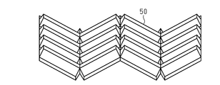
- this hollow structure includes a core layer obtained by folding a sheet material 50 having irregularities, and two skin layers respectively bonded to both surfaces of the core layer.
- a plurality of cells are arranged in the hollow structure.
- the partition wall located between adjacent cells has a two-layer structure.
- One of the ends of the partition wall has a joining part in which two layers are joined to each other, and the other end has a folding part.
- An object of the present disclosure is to provide a hollow structure body having improved impact resistance efficiently.
- the hollow structure has a plurality of cells.
- the hollow structure includes a core layer having a plurality of first walls, a plurality of second walls and a plurality of partition walls, and first and second skin layers respectively bonded to both surfaces of the core layer.
- the plurality of cells include a plurality of first cells and a plurality of second cells. Each of the first cells is partitioned by the first wall, the plurality of partition walls extending from the first wall, and the second skin layer. Each of the second cells is partitioned by the second wall, the plurality of partition walls extending from the second wall, and the first skin layer.
- the plurality of first cells arranged in one direction is a first cell row
- the plurality of second cells arranged in one direction is a second cell row
- the plurality of partition walls are a plurality of first partition walls having a two-layer structure located between the adjacent first cells of the first cell row, and the adjacent second cells of the second cell row.
- a plurality of second partition walls each having a two-layer structure located between the plurality of second partition walls.
- the first partition wall has, at an end closer to the first wall, a first joint portion in which two layers constituting the first partition wall are joined to each other, and is far from the first wall. It has a first folded portion at one end.
- the second partition wall has, at an end closer to the second wall, a second bonding portion in which two layers forming the second partition wall are bonded to each other, and is far from the second wall. It has a second folded portion at one end.
- the joining force of the first joining portion is larger than the joining force of the second joining portion.
- FIG. 1A The perspective view of the hollow structure body concerning an embodiment. Sectional drawing which followed the 1B-1B line of FIG. 1A. Sectional drawing which followed the 1C-1C line of FIG. 1A.
- seat material of FIG. 2A The perspective view which shows the state which folded the sheet
- FIG. 8 is an end view taken along line 8-8 of FIG.
- FIG. 9 is an end view taken along the line 9-9 of FIG. 6.
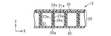
- the hollow structure 10 includes a core layer 20 and first and second skin layers 30 and 40 bonded (for example, welded) to both surfaces of the core layer 20.
- the core layer 20 has a plurality of first walls 21a, a plurality of second walls 21b, and a plurality of partition walls 23, and partitions a plurality of cells S having a hexagonal prism shape.
- the plurality of cells S include a plurality of first cells S1 and a plurality of second cells S2.
- Each first cell S1 is partitioned by a hexagonal first wall 21a, a plurality of partition walls 23 extending from the first wall 21a toward the second skin layer 40, and a second skin layer 40.
- Each second cell S2 is partitioned by a hexagonal second wall 21b, a plurality of partition walls 23 extending from the second wall 21b toward the first skin layer 30, and a first skin layer 30.
- the core layer 20 includes a plurality of first cell rows S1a in which a plurality of first cells S1 are arranged in one direction (X axis) and a plurality of a plurality of second cells S2 arranged in one direction (X axis). And a second cell row S2a.
- the X axis, the Y axis, and the Z axis are direction axes orthogonal to each other, and the thickness direction of the hollow structure 10 is a direction along the Z axis.
- the first and second cell rows S1a and S2a extend in a direction orthogonal to the thickness direction Z.
- the plurality of partition walls 23 include a plurality of first partition walls 23a, a plurality of second partition walls 23b, and a plurality of third partition walls 23c.
- the first and second partition walls 23a and 23b have a two-layer structure.
- the third partition wall 23c has a one-layer structure.
- the first partition wall 23a is located between the adjacent first cells S1 of the first cell row S1a.
- the first partition wall 23a has a first end (an end closer to the first wall 21a) in the thickness direction Z, in which the surfaces of the two layers forming the first partition wall 23a are joined to each other by welding.
- the joint portion 24a is provided, and the first folded portion 25a is provided at the second end (the end farther from the first wall 21a) in the thickness direction Z.
- the two layers forming the first partition wall 23a are not joined to each other between the first joint portion 24a and the first folded portion 25a.
- the second partition wall 23b is located between the adjacent second cells S2 of the second cell row S2a.
- the second partition wall 23b has a second joint portion 24b in which two layers constituting the second partition wall 23b are joined to each other by welding at a second end (an end closer to the second wall 21b) in the thickness direction Z. And has the second folded portion 25b at the first end (the end farther from the second wall 21b) in the thickness direction Z.
- the two layers forming the second partition wall 23b are not joined to each other between the second joint portion 24b and the second folded portion 25b.
- the two layers forming the first partition wall 23a are not joined to each other near the center in the thickness direction Z. Therefore, the first communication portion 26a that allows the first cells S1 to communicate with each other may be formed between the first cells S1 adjacent to each other in the Y direction. Similarly, the two layers forming the second partition wall 23b are not joined to each other near the center in the thickness direction Z. Therefore, the second communicating portion 26b that allows the second cells S2 to communicate with each other may be formed between the second cells S2 adjacent to each other in the Y direction.
- the first communication portion 26a is a gap that can be formed between two first partition walls 23a that are adjacent to or in contact with each other.
- the second communication portion 26b is a gap that can be formed between two adjacent second partition walls 23b. That is, the unbonded portions of the two layers may allow fluid to flow between the two layers, even though they appear to be in contact with each other.
- the third partition wall 23c is located between the first cell S1 and the second cell S2.
- the first cell row S1a and the second cell row S2a are alternately arranged along the Y axis orthogonal to the X axis while sharing the plurality of third partition walls 23c.
- the six partition walls 23 that partition each first cell S1 include two first partition walls 23a and four third partition walls 23c, and the six partition walls 23 that partition each second cell S2 are 2 It includes one second partition wall 23b and four third partition walls 23c.
- the core layer 20 and the skin layers 30 and 40 are made of thermoplastic resin.
- the thermoplastic resin forming the core layer 20 and the skin layers 30 and 40 is well known in the art, and the material thereof is not particularly limited. Examples of the thermoplastic resin are polypropylene resin, polyamide resin, polyethylene resin, acrylonitrile-butadiene-styrene copolymer resin, acrylic resin, polybutylene terephthalate resin and the like.
- the thermoplastic resins forming the core layer 20 and the skin layers 30 and 40 may be made of the same material or may be different from each other.
- the core layer 20 and the skin layers 30 and 40 of this embodiment are both made of polypropylene resin.
- the thickness of the first wall 21a, the partition wall 23, and the second wall 21b of the core layer 20 is not particularly limited, but is, for example, 0.1 mm to 0.5 mm.
- the thickness of the skin layers 30 and 40 is not particularly limited, but is, for example, 0.3 mm to 0.6 mm.
- the thickness of the first wall 21a may be thicker than the thickness of the second wall 21b.
- the method for manufacturing the hollow structure 10 includes a folding step, a heating step, and a laminating step.
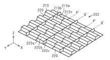
- a flat sheet material 200 as shown in FIG. 2A is formed by folding to form a core layer.
- the sheet material 200 is vacuum formed so as to have a predetermined unevenness.
- the sheet material 200 includes band-shaped first and second bulging portions 210 and 220 extending in the X direction.
- the first bulging portions 210 and the second bulging portions 220 have a width in the Y direction and are arranged alternately along the Y axis.
- the first bulging portion 210 and the second bulging portion 220 project in opposite directions along the Z axis.
- the first bulging portion 210 and the second bulging portion 220 have the same shape and are arranged at positions shifted by 1/2 pitch along the X axis. There is.
- the first bulging portion 210 has a first bulging surface 210a, two section screens 210b, and two end surfaces 210c.
- the cross-sectional shape of the first bulging portion 210 taken along a plane including the Y axis and the Z axis is a trapezoid obtained by dividing the regular hexagon by the longest diagonal line.
- the two end faces 210c are located at the boundary line P′ shown in FIG. 2A.
- the angle formed by the end surface 210c and the first bulging surface 210a is about 90°.
- the second bulging portion 220 has a second bulging surface 220a, two section screens 220b, and two end surfaces 220c.
- the cross-sectional shape of the second bulging portion 220 taken along a plane including the Y axis and the Z axis is a trapezoid obtained by dividing the regular hexagon by the longest diagonal line.
- the two end faces 220c are located at the boundary line Q′ shown in FIG. 2A.
- the angle formed by the end surface 220c and the second bulging surface 220a is about 90°.
- the length of the second bulging portion 220 along the X axis, that is, the length between the two end surfaces 220c is the length of the first bulging portion 210 along the X axis, that is, the length between the two end surfaces 210c. Is the same.
- the end surface 220c of the second bulging portion 220 is located at the center of the first bulging portion 210 in the X direction.
- the division screen 210b of the first bulging portion 210 and the division screen 220b of the second bulging portion 220 have the same shape.
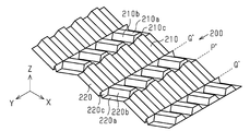
- the core layer 20 is formed by sequentially folding the sheet material 200 along the boundary lines P′ and Q′.
- the sheet material 200 is mountain-folded along the boundary line P′ and valley-folded along the boundary line Q′.
- the first bulging portion 210 is valley-folded at a boundary line Q′ located at the center in the X direction, and the first bulging surfaces 210a that are divided with the boundary line Q′ as a boundary are separated from each other. Abut.
- the first bulging surfaces 210a that are in contact with each other serve as the first partition wall 23a
- the partition screen 210b serves as the third partition wall 23c.
- the two end faces 210c arranged along the X-axis form the first wall 21a having a single-layer structure.
- the second end (lower end in FIG. 2C) of the first partition wall 23a defines the first opening 27a.
- the second bulging portion 220 is mountain-folded at a boundary line P′ located at the center of the adjacent boundary lines Q′ in the X direction, and the second bulging surfaces 220 a that are divided with the boundary line P′ as a boundary are separated from each other. Abut. In the thus-folded second bulging portion 220, the second bulging surfaces 220a that are in contact with each other serve as the second partition wall 23b, and the partition screen 220b serves as the third partition wall 23c. At the second end (lower end in FIG. 2C) of the second partition wall 23b, the two end surfaces 220c arranged along the X-axis form the second wall 21b having a single-layer structure. The first end (upper end in FIG. 2C) of the second partition wall 23b defines the second opening 27b.
- the first cell S1 having the first opening 27a is divided by the first wall 21a and the partition wall 23 extending from the first wall 21a, and the second wall 21b and the second wall 21b are formed.
- the partition wall 23 extending from 21b partitions the second cell S2 having the second opening 27b.
- the surfaces of the first wall 21a and the second wall 21b are smooth surfaces.
- the “smooth surface” means a flat surface that has no unevenness when visually observed.
- the thickness of the portion where the amount of deformation due to evacuation is large becomes thinner than the thickness of the other portions. Therefore, when the sheet material 200 is evacuated, the second bulging portion 220 is evacuated more strongly in the bulging direction, so that the thickness of the second wall 21b becomes smaller than the thickness of the first wall 21a. As a result, the thickness of the first wall 21a can be made relatively thicker than the thickness of the second wall 21b.
- the thickness of the first wall 21a is not particularly limited, but may be, for example, twice or more the thickness of the second wall 21b.
- the thickness of the partition wall 23 gradually increases from the second surface of the core layer 20 toward the first surface.
- the plurality of cells S are neatly aligned along the X axis and the Y axis.
- the thickness of the partition wall 23 near the second surface of the core layer 20 is smaller than that near the first surface. Therefore, on the second surface of the core layer 20, the plurality of cells S arranged along the Y axis are arranged so as to meander slightly. At this time, in the vicinity of the second surface of the core layer 20, the crushing amount of the two layers forming the partition wall 23 can be increased to bring the two layers into close contact with each other. Therefore, in the heating step described later, the two layers forming the partition wall 23 can be more reliably welded to each other near the second surface.
- a plurality of cells S arranged along the Y axis may be arranged in a meandering manner.
- Heating process In the heating step, the core layer 20 produced in the folding step is pressed while being heated. As a result, the first end of the first partition wall 23a is heat-welded (hereinafter, also simply referred to as "welding"), and the second end of the second partition wall 23b is heat-welded.
- a method of heating the core layer 20 by a heating device while conveying the core layer 20 by a conveyor can be adopted.
- the first and second surfaces of the core layer 20 are sandwiched between the first and second conveyors, respectively, and the core layer 20 is heated by a heater arranged inside the first and second conveyors.
- the core layer 20 is conveyed along the X axis.
- a load is applied to the core layer 20 along the X axis.
- a load may be applied to the core layer 20 along the Z axis by sandwiching the core layer 20 between the first and second conveyors arranged along the Z axis.
- the two layers forming the first partition wall 23a are welded to each other near the first wall 21a.
- the first joint portion 24a is formed.
- the two layers forming the first partition wall 23a are welded to each other near the second wall 21b.
- the second joint portion 24b is formed.
- the thickness of the partition wall 23 near the first wall 21a is thicker than the thickness near the second wall 21b. Therefore, when the core layer 20 is pressed from both sides, a relatively larger load is applied to the vicinity of the first wall 21a than to the vicinity of the second wall 21b. That is, the length dimension along the X axis of the core layer 20 obtained by the folding step is longer at the position in contact with the first wall 21a than at the position in contact with the second wall 21b. Therefore, the load applied to the core layer 20 by the first and second conveyors becomes larger at the first end of the first partition wall 23a. By welding under a larger load, the joining force becomes larger. Therefore, the joining force of the first joining portion 24a is larger than the joining force of the second joining portion 24b.
- the first and second sheets are joined to the first and second surfaces of the core layer 20, respectively. More specifically, the first and second sheets to be the skin layers 30 and 40 are heated and brought into contact with both surfaces of the core layer 20 for a predetermined time. As a result, the first and second skin layers 30 and 40 are joined (welded) to both surfaces of the core layer 20, respectively.
- the flat hollow structure 10 including a plurality of cells S is manufactured through the above manufacturing steps.
- the use of the hollow structure 10 is not particularly limited. Since the hollow structure 10 has a honeycomb structure, it has excellent impact resistance, sound insulation, and heat insulation. Therefore, the hollow structure 10 can be appropriately used for applications requiring these characteristics. Examples of applications of the hollow structure 10 are luggage boards, shelves, containers, and the like.
- the first skin layer 30 may be the surface or the second skin layer 40 may be the surface.
- the cell in which the plurality of cells S are neatly aligned may be bonded to the skin layer, or the plurality of cells S are arranged in a slightly meandering manner. It may be bonded to a skin layer of which one is the surface.
- the hollow structure 10 can improve the impact resistance from one surface side, that is, the side where the first joint portion 24a is provided in the thickness direction. Therefore, impact resistance can be efficiently improved.
- the bending strength of the hollow structure 10 can be improved as compared with a mode in which the joining force of the first joining portion 24a is the same as the joining force of the second joining portion 24b.
- the thickness of the first wall 21a is relatively thicker than the thickness of the second wall 21b. This is because the wall thickness of the end face 210c of the sheet material 200 that becomes the core layer 20 is relatively thicker than the wall thickness of the end face 220c. Therefore, the strength of the first wall 21a can be relatively increased. Therefore, in the hollow structure 10, the impact resistance from the first surface side in the thickness direction, that is, the side where the first joint portion 24a is provided is further improved.
- the thickness of the first end (the end that intersects the first wall 21a) of the partition wall 23 is relatively thicker than the thickness of the second end (the end that intersects the second wall 21b).
- the intersecting portion between the partition wall 23 and the first wall 21a can be crushed a little and the intersecting portion can be more reliably joined (for example, welded) to the first skin layer 30. That is, even if the vicinity of the first end of the partition wall 23 is slightly crushed, the strength of the partition wall 23 itself is secured, and therefore it is possible to prevent the partition wall 23 from being crushed excessively.
- the partition wall 23 has a thickness that continuously decreases from the first end toward the second end.
- the thickness of the first end of the partition wall 23 is thicker than the thickness of the second end. Therefore, for example, when the core layer 20 is heated from both sides, the amount of resin melted near the first end of the partition wall 23 is larger than the amount of resin melted near the second end. As a result, a large amount of resin that is melted by heating can be secured, and the first end of the partition wall 23 can be more reliably welded. On the other hand, since the second end of the partition wall 23 is relatively thin, it is easily heated by the heat from the heating device. Therefore, the second end of the partition wall 23 can be efficiently heated and more reliably welded.
- the first cell row S1a and the second cell row S2a are arranged alternately. Therefore, the impact resistance can be made more uniform on both surfaces of the hollow structure 10.
- the first joint portion 24a is a portion where the two layers forming the first partition wall 23a are welded to each other
- the second joint portion 24b is the portion where the two layers forming the second partition wall 23b are welded to each other. Is. Therefore, the configurations of the first joint portion 24a and the second joint portion 24b can be simplified.
- the first communication portion 26a is formed between the first cells S1 adjacent to each other in the Y direction
- the second communication portion 26b is formed between the second cells S2 adjacent to each other in the Y direction. Therefore, when the hollow structure 10 is heated and bent, the heated air in the first cell S1 and the second cell S2 passes through the first communication portion 26a and the second communication portion 26b. And spreads over the entire hollow structure 10. Thereby, expansion of the 1st wall 21a and the 2nd wall 21b can be controlled.
- the present embodiment can be implemented with the following modifications.
- the configurations included in the present embodiment and the following modifications can be implemented in combination with each other within a technically consistent range.
- the first joint portion 24a and the second joint portion 24b may be formed.
- the joining force of the first joining portion 24a and the joining force of the second joining portion 24b can be changed by adjusting the type of the adhesive and the application state of the adhesive.
- the core layer 20 may not have at least one of the first communication portion 26a and the second communication portion 26b.
- the two layers forming the first partition wall 23a may be joined at their entire surfaces to each other.
- the two layers forming the second partition wall 23b may be joined at their entire surfaces to each other.
- the hollow structure 10 does not have to be a flat plate. At least a part of the hollow structure 10 may be curved so that the outer surface defined by the first skin layer 30 is a convex surface and the outer surface defined by the second skin layer 40 is a concave surface.
- the hollow structure 10 can be curved as described above by press molding after the laminating step. Thereby, impact resistance from the convex surface side of the hollow structure 10 is improved.
- the outer surface defined by the first skin layer 30 may be a concave surface and the outer surface defined by the second skin layer 40 may be a convex surface.
- a curved portion can be formed at an arbitrary position by press-molding a part of the hollow structure 10 after the laminating step.
- the height dimension of the convex surface 31 and the depth dimension of the concave surface 41 may be larger than the thickness dimension of the flat portion of the hollow structure 10.
- the hollow structure 10 may have a plurality of curved portions. In this case, the hollow structure 10 may have a plurality of bending portions that bend in different directions.
- At least one of the first wall 21a and the second wall 21b may have an uneven shape or an uneven pattern on the outer surface.
- Such a concavo-convex shape can generate an anchor effect when joining (for example, welding) the sheets to be the skin layer. Therefore, the bonding strength of the skin layers 30 and 40 can be further increased. By increasing the joint strength of the skin layers 30 and 40, the impact resistance of the hollow structure 10 can be improved.
- the first wall 21a (end surface 210c) of the core layer 20 may have a linear recess 28a extending along the Y axis.
- the recess 28a is recessed in the direction in which it is pulled during vacuum forming.
- the recessed portion 28a can increase the welding area between the core layer 20 and the skin layers 30 and 40.
- the second wall 21b (end surface 220c) of the core layer 20 may have a plurality of wrinkle-shaped recesses 28b extending along the Y axis. Since the wall thickness of the end surface 220c is relatively thin, it is easily softened by heating in the heating process.
- the recess 28b can be formed by setting a higher heating temperature in the heating process.
- one of the first and second openings 27a and 27b does not have to be a regular hexagon.
- the position of the first cell row S1a along the X axis is displaced, so that the shape of the second opening 27b is distorted and is not a regular hexagon.
- the cells S1 and S2 arranged alternately along the Y axis appear to meander.
- FIG. 7 schematically shows a die 251 for vacuum forming the sheet material 200 and the sheet material 200 immediately after vacuum forming.
- the mold 251 has a plurality of suction holes 252 for sucking the sheet material 200.
- the mold 251 may be a cylindrical drum.
- the long sheet material 200 can be continuously formed by transporting the sheet material 200 while being wound around the cylindrical mold 251.
- the second bulging portion 220 is extended by being sucked by the mold 251 through the suction hole 252 as shown by the white arrow in FIG. 7. As a result, the second bulging portion 220 is relatively thinner than the first bulging portion 210. At this time, the intersection of the second bulging surface 220a, the two division screens 220b, and the two end surfaces 220c may not be a sharp corner. In this case, the second bulging surface 220a, the two section screens 220b, and the two end surfaces 220c of the second bulging portion 220 are curved so as to bulge outward toward the mold 251, and the second bulging portion 220 has four bulging portions. Has rounded corners.
- the first bulging surface 210a of the first bulging portion 210, the two ward screens 210b (the ward screen 220b) and the two end faces 210c are curved so as to dent inward toward the mold 251 and the first bulge is performed.
- Portion 210 has four sharp corners.
- the two first bulging surfaces 210a forming the first partition wall 23a are curved so that their outer edges are close to each other.
- the plurality of first walls 21a and the plurality of first openings 27a are regular hexagons
- the plurality of second walls 21b and the plurality of second openings 27b are distorted hexagons.
- the plurality of first walls 21a and the plurality of second openings 27b are distorted hexagons.
- the meandering state of the cell S changes depending on which of the first wall 21a and the second wall 21b is a regular hexagon. Even when the plurality of cells S are distorted or meandered, each cell S maintains the hexagonal prism shape, and thus impact strength and bending strength are less likely to decrease.
- the distortion and meandering of the plurality of cells S may occur due to, for example, the first bulging surface 210a being curved or the second bulging portion 220 having a rounded corner.
- the core layer 20 can be formed while the cells S are distorted and meandered. Therefore, it is possible to increase the molding speed of the sheet material 200 and the core layer 20 to improve work efficiency, and to suppress the occurrence of defective molding of the sheet material 200 and the core layer 20.
- the two second bulging surfaces 220a forming the second partition wall 23b may be curved so that the centers of the surfaces approach each other. In this case, the impact resistance of the second partition wall 23b is improved.
- At least one of the first wall 21a and the second wall 21b may have a convex portion.
- the convex portion 110 of the first wall 21a was melted and projected by increasing the heating temperature or the pressing force in the heating step. It is a part.
- the protrusion 110 may protrude in a direction in which the first surface 20a of the core layer 20 (a surface joined to the first skin layer 30) extends, or may protrude in a direction intersecting with the first surface 20a. The protrusion 110 allows the core layer 20 to be more reliably welded to the first skin layer 30.
- the convex portion 111 protruding from the first folded portion 25a may be formed by heating or pressing the first folded portion 25a.
- the convex portion 111 is a portion for welding the first partition wall 23a (first folded portion 25a) to the second skin layer 40. As a result, the welding area of the core layer 20 to the second skin layer 40 increases, and the welding strength increases.
- the convex portion 113 of the second wall 21b is a portion where the second wall 21b is melted and protrudes.
- the protrusion 113 may protrude in the direction in which the second surface 20b (the surface joined to the second skin layer 40) of the core layer 20 extends, or may protrude in the direction intersecting with the second surface 20b.
- the protrusion 113 allows the core layer 20 to be more reliably welded to the second skin layer 40.
- the convex portion 112 protruding from the second folded portion 25b may be formed by heating or pressing the second folded portion 25b.
- the convex 112 serves as a portion for welding the second partition wall 23b (second folded portion 25b) to the first skin layer 30.
- the welding area of the core layer 20 with respect to the first skin layer 30 increases, so that the welding strength increases.
- the opening areas of the first and second opening portions 27a and 27b can be narrowed by projecting the protruding portions 111 and 112 from the folded-back portions 25a and 25b, respectively. Therefore, the welding strength of the skin layers 30 and 40 is improved.
- the skin layers 30 and 40 may be attached to both sides of the core layer 20 with an adhesive.
- the adhesive may be applied to the sheets that will be the skin layers 30 and 40, or may be applied to the core layer 20.
- the skin layers 30 and 40 may be non-woven fabric, for example. Alternatively, a nonwoven fabric may be attached to the outer surfaces of the skin layers 30 and 40.
- the hollow structure 10 may have a through hole that penetrates at least one of the core layer 20 and the skin layers 30 and 40 in the thickness direction (Z direction).
- the shape of the cell S included in the hollow structure 10 is not limited to a hexagonal column, and may be, for example, any polygonal column, a circle, or an elliptic column.
- the outer edge of the hollow structure 10 may be crushed so that the first skin layer 30 approaches the second skin layer 40.
- the outer edge of the first skin layer 30 and the outer edge of the first wall 21 a are curved so as to approach the first skin layer 30.
- the crushed outer edge portion 105, the first skin layer 30, the first wall 21a, and the partition wall 23 are integrated into a solid shape.
- the first partition wall 23a is crushed near the thickest first end. Therefore, the strength of the solid outer edge portion 105 is higher and the surface of the outer edge portion 105 is smoother than when the vicinity of the second end where the thickness of the first partition wall 23a is relatively thin is crushed.
Landscapes
- Engineering & Computer Science (AREA)
- Mechanical Engineering (AREA)
- Laminated Bodies (AREA)
Abstract
複数のセルを有する中空構造体は、コア層と、第1及び第2スキン層と、を備える。前記複数のセルは、複数の第1セルと、複数の第2セルと、を含む。一方向に並ぶ前記複数の第1セルが第1セル列であり、前記一方向に並ぶ前記複数の第2セルが第2セル列である。前記複数の区画壁は、前記第1セル列の隣り合う前記第1セル同士の間に位置する複数の第1区画壁と、前記第2セル列の隣り合う前記第2セル同士の間に位置する複数の第2区画壁と、を含む。前記第1区画壁は第1接合部を有する。前記第2区画壁は第2接合部を有する。前記第1接合部の接合力は、前記第2接合部の接合力よりも大きい。
Description
本開示は、中空構造体及びラゲッジボードに関する。
特許文献1には、保護材等に使用される中空構造体について記載されている。
この中空構造体は、図11に示すように、凹凸を有するシート材50を折り込むことによって得られるコア層と、このコア層の両面にそれぞれ接合される2つのスキン層とを備える。この中空構造体内には、複数のセルが並んでいる。隣り合うセル同士の間に位置する区画壁は2層構造を有する。この区画壁の両端のうちいずれか一方の端部は、2層が互いに接合された接合部を有し、他方の端部は折返し部を有する。
上述の中空構造体では、耐衝撃性のさらなる向上が求められている。本開示の目的は、耐衝撃性を効率良く向上させた中空構造体を提供することにある。
本開示の一態様に係る中空構造体は、複数のセルを有する。前記中空構造体は、複数の第1壁、複数の第2壁及び複数の区画壁を有するコア層と、前記コア層の両面にそれぞれ接合された第1及び第2スキン層と、を備える。前記複数のセルは、複数の第1セルと、複数の第2セルと、を含む。前記各第1セルは、前記第1壁と、前記第1壁から延びる複数の前記区画壁と、前記第2スキン層とによって区画される。前記各第2セルは、前記第2壁と、前記第2壁から延びる複数の前記区画壁と、前記第1スキン層とによって区画される。一方向に並ぶ前記複数の第1セルが第1セル列であり、前記一方向に並ぶ前記複数の第2セルが第2セル列である。前記複数の区画壁は、前記第1セル列の隣り合う前記第1セル同士の間に位置する2層構造を有する複数の第1区画壁と、前記第2セル列の隣り合う前記第2セル同士の間に位置する2層構造を有する複数の第2区画壁と、を含む。前記第1区画壁は、前記第1壁に近い方の端に、前記第1区画壁を構成する2層同士が互いに接合された第1接合部を有し、かつ、前記第1壁から遠い方の端に第1折返し部を有する。前記第2区画壁は、前記第2壁に近い方の端に、前記第2区画壁を構成する2層同士が互いに接合された第2接合部を有し、かつ、前記第2壁から遠い方の端に第2折返し部を有する。前記第1接合部の接合力は、前記第2接合部の接合力よりも大きい。
中空構造体の実施形態を説明する。
明細書および請求の範囲において、「第1」、「第2」などの用語は、同様な構成要素を区別するために使用するものであり、必ずしも特定の連続する、または時系列に従った順番を表すために使用するのではない。
明細書及び/または特許請求の範囲に開示された全ての特徴は、当初の開示の目的のために、ならびに、実施形態及び/または特許請求の範囲における特徴の組み合わせから独立して特許請求の範囲に記載の発明を限定する目的のために、互いに別個にかつ独立して開示されることを意図したものである。
開示された実施形態は、本発明の範囲を限定するものと見なされるべきではなく、同等の機能または同じ機能を果たす別個の実施形態の特徴は、補正された請求項の範囲内で開示された実施形態間で交換することができる。端点による数値範囲の列挙は、その範囲内のすべての数を含む。例えば、1から5は、1、1.5、2、2.75、3、3.80、4、および5を含む。
図1Aに示すように、中空構造体10は、コア層20と、コア層20の両面にそれぞれ接合(例えば、溶着)された第1及び第2スキン層30,40とを備える。コア層20は、複数の第1壁21aと、複数の第2壁21bと、複数の区画壁23と、を有して、六角柱の形状を有する複数のセルSを区画する。複数のセルSは、複数の第1セルS1と複数の第2セルS2とを含む。各第1セルS1は、六角形状の第1壁21aと、第1壁21aから第2スキン層40に向けて延びる複数の区画壁23と、第2スキン層40とによって区画される。各第2セルS2は、六角形状の第2壁21bと、第2壁21bから第1スキン層30に向けて延びる複数の区画壁23と、第1スキン層30とによって区画される。
コア層20は、複数の第1セルS1が一方向(X軸)に沿って並ぶ複数の第1セル列S1aと、複数の第2セルS2が一方向(X軸)に沿って並ぶ複数の第2セル列S2aとを有する。X軸、Y軸及びZ軸は互いに直交する方向軸であって、中空構造体10の厚さ方向はZ軸に沿う方向である。第1及び第2セル列S1a,S2aは、厚さ方向Zと直交する方向に延びる。
図1B及び図1Cに示すように、複数の区画壁23は、複数の第1区画壁23aと、複数の第2区画壁23bと、複数の第3区画壁23cとを含む。第1及び第2区画壁23a,23bは、2層構造を有する。第3区画壁23cは1層構造を有する。
第1区画壁23aは、第1セル列S1aの隣り合う第1セルS1同士の間に位置する。第1区画壁23aは、厚さ方向Zにおける第1端(第1壁21aに近い方の端)に、第1区画壁23aを構成する2層の表面同士が溶着により互いに接合された第1接合部24aを有し、かつ、厚さ方向Zにおける第2端(第1壁21aから遠い方の端)に、第1折返し部25aを有する。第1区画壁23aを構成する2層は、第1接合部24aと第1折返し部25aの間において、互いに接合されていない。
第2区画壁23bは、第2セル列S2aの隣り合う第2セルS2同士の間に位置する。第2区画壁23bは、厚さ方向Zにおける第2端(第2壁21bに近い方の端)に、第2区画壁23bを構成する2層が互いに溶着により接合された第2接合部24bを有し、かつ、厚さ方向Zにおける第1端(第2壁21bから遠い方の端)に、第2折返し部25bを有する。第2区画壁23bを構成する2層は、第2接合部24bと第2折返し部25bの間において、互いに接合されていない。
第1区画壁23aを構成する2層は、厚さ方向Zの中央付近において互いに接合されていない。そのため、Y方向に隣り合う第1セルS1同士の間には、第1セルS1同士を互いに連通させる第1連通部26aが形成され得る。同様に、第2区画壁23bを構成する2層は、厚さ方向Zの中央付近において互いに接合されていない。そのため、Y方向に隣り合う第2セルS2同士の間には、第2セルS2同士を互いに連通させる第2連通部26bが形成され得る。具体的には、第1連通部26aは、互いに隣接または当接する2つの第1区画壁23aの間に形成され得る隙間である。同様に、第2連通部26bは、隣接する2つの第2区画壁23bの間に形成され得る隙間である。すなわち、2層の互いに接合されていない部分は、互いに接触しているように見えたとしても、2層の間を流体が流動し得る。
第3区画壁23cは、第1セルS1と第2セルS2との間に位置する。第1セル列S1aと第2セル列S2aは、複数の第3区画壁23cを共有した状態で、X軸と直交するY軸に沿って交互に配置されている。各第1セルS1を区画する6つの区画壁23は、2つの第1区画壁23aと4つの第3区画壁23cとを含み、各第2セルS2を区画する6つの区画壁23は、2つの第2区画壁23bと4つの第3区画壁23cとを含む。
コア層20及びスキン層30,40は、熱可塑性樹脂製である。コア層20及びスキン層30,40を構成する熱可塑性樹脂は、従来周知のものであってその材質は特に限定されない。熱可塑性樹脂の例は、ポリプロピレン樹脂、ポリアミド樹脂、ポリエチレン樹脂、アクリロニトリル-ブタジエン-スチレン共重合体樹脂、アクリル樹脂、ポリブチレンテレフタレート樹脂等である。コア層20及びスキン層30,40を構成する熱可塑性樹脂は、いずれも同じ材質であってもよいし、互いに異なっていてもよい。本実施形態のコア層20及びスキン層30,40は、いずれもポリプロピレン樹脂製である。
コア層20が有する第1壁21a、区画壁23、及び、第2壁21bの厚さは、特に限定されないが、例えば、0.1mm~0.5mmである。スキン層30,40の厚さは、特に限定されないが、例えば、0.3mm~0.6mmである。
第1壁21aの厚さは、第2壁21bの厚さよりも厚くてもよい。
中空構造体10の製造方法について説明する。
中空構造体10の製造方法は、折り込み工程と、加熱工程と、積層工程とを含む。
(折り込み工程)
折り込み工程では、図2Aに示すような、平板状のシート材200を折り込み成形して、コア層を作製する。シート材200は、予め規定された凹凸を有するように真空成形される。
折り込み工程では、図2Aに示すような、平板状のシート材200を折り込み成形して、コア層を作製する。シート材200は、予め規定された凹凸を有するように真空成形される。
シート材200は、X方向に延びる帯状の第1及び第2膨出部210,220を備える。第1膨出部210と第2膨出部220とは、Y方向に幅を有して、Y軸に沿って交互に配置されている。第1膨出部210と第2膨出部220とは、Z軸に沿って、互いに反対方向に突出している。シート材200を平面視すると、第1膨出部210と第2膨出部220とは、同じ形状を有して、かつ、X軸に沿って1/2ピッチずつずれた位置に配置されている。
第1膨出部210は、第1膨出面210aと、2つの区画面210bと、2つの端面210cとを有する。第1膨出部210をY軸及びZ軸を含む面で切った断面の形状は、正六角形を最も長い対角線で二分した台形である。2つの端面210cは、図2Aに示す境界線P´の位置にある。端面210cと第1膨出面210aとのなす角度は約90゜である。
第2膨出部220は、第2膨出面220aと、2つの区画面220bと、2つの端面220cとを有する。第2膨出部220をY軸及びZ軸を含む面で切った断面の形状は、正六角形を最も長い対角線で二分した台形である。2つの端面220cは、図2Aに示す境界線Q´の位置にある。端面220cと第2膨出面220aとのなす角度は約90゜である。第2膨出部220のX軸に沿う長さ、つまり、2つの端面220c間の長さは、第1膨出部210のX軸に沿う長さ、つまり、2つの端面210c間の長さと同じである。第2膨出部220の端面220cは、第1膨出部210のX方向における中央に位置している。第1膨出部210の区画面210bと第2膨出部220の区画面220bとは、同じ形状を有する。シート材200が境界線P´、Q´に沿って順次折り込まれることにより、コア層20が形成される。
図2Bに示すように、シート材200は、境界線P´に沿って山折りされ、境界線Q´に沿って谷折りされる。図2Cに示すように、第1膨出部210は、X方向における中央に位置する境界線Q´で谷折りされて、その境界線Q´を境界として分割される第1膨出面210a同士が当接する。このように折り込まれた第1膨出部210は、互いに当接した第1膨出面210aが第1区画壁23aとなり、区画面210bが第3区画壁23cとなる。第1区画壁23aの第1端(図2Cでは上端)において、X軸に沿って並ぶ2つの端面210cが1層構造の第1壁21aとなる。第1区画壁23aの第2端(図2Cでは下端)は第1開口部27aを画定する。
第2膨出部220は、隣り合う境界線Q´のX方向における中央に位置する境界線P´で山折りされて、その境界線P´を境界として分割される第2膨出面220a同士が当接する。このように折り込まれた第2膨出部220は、互いに当接した第2膨出面220aが第2区画壁23bとなり、区画面220bが第3区画壁23cとなる。第2区画壁23bの第2端(図2Cでは下端)において、X軸に沿って並ぶ2つの端面220cが1層構造の第2壁21bとなる。第2区画壁23bの第1端(図2Cでは上端)は第2開口部27bを画定する。
このように、折り込み工程では、第1壁21aと、第1壁21aから延びる区画壁23とによって、第1開口部27aを有する第1セルS1が区画され、第2壁21bと、第2壁21bから延びる区画壁23とによって、第2開口部27bを有する第2セルS2が区画される。第1壁21a及び第2壁21bの表面は平滑面である。「平滑面」とは、目視した際に凹凸が無く、平らな面を意味する。
シート材200は、凹凸形状に真空成形する際に、真空引きによる変形量が大きかった部分の肉厚が、その他の部分の肉厚よりも薄くなる。そのため、シート材200を真空引きする際に、第2膨出部220を膨出方向により強く真空引きすることにより、第2壁21bの厚さが第1壁21aの厚さより薄くなる。その結果、第1壁21aの厚さを第2壁21bの厚さよりも相対的に厚くすることができる。
具体的には、図2Aにおいて、シート材200の裏面(図示されていない下面)を真空成形の金型に向き合わせて成形すると、境界線P´を挟んで並ぶ2つの端面210cがコア層20の第1面(図1Bの上面)になり、境界線Q´を挟んで並ぶ端面220cがコア層20の第2面(図1Bの下面)になる。そのため、コア層20の第1面(端面210c)を画定する第1壁21aの肉厚が、コア層20の第2面(端面220c)を画定する第2壁21bの肉厚より厚くなる。第1壁21aの厚さは、特に限定されないが、例えば、第2壁21bの厚さの2倍以上であってもよい。区画壁23の厚さは、コア層20の第2面から第1面に向かって徐々に増加する。
コア層20の第1面において、複数のセルSはX軸及びY軸に沿って綺麗に整列している。コア層20の第2面付近では、第1面付近よりも区画壁23の厚さが薄い。そのため、コア層20の第2面において、Y軸に沿って並ぶ複数のセルSは、若干蛇行するように並ぶ。このとき、コア層20の第2面付近では、区画壁23を構成する2層の潰し量を多くして、2層を互いに密着させることができる。そのため、後述の加熱工程において、第2面付近において、区画壁23を構成する2層同士をより確実に溶着することができる。区画壁23の厚さの違いによっては、図6に示すように、コア層20の第1面において、Y軸に沿って並ぶ複数のセルSが蛇行するように並ぶことがある。
(加熱工程)
加熱工程では、折り込み工程で作製したコア層20を加熱しながら押圧する。これにより、第1区画壁23aの第1端を熱溶着(以下、単に「溶着」ともいう。)し、かつ、第2区画壁23bの第2端を熱溶着する。
加熱工程では、折り込み工程で作製したコア層20を加熱しながら押圧する。これにより、第1区画壁23aの第1端を熱溶着(以下、単に「溶着」ともいう。)し、かつ、第2区画壁23bの第2端を熱溶着する。
コア層20を加熱する方法としては、例えば、コア層20をコンベヤ(図示省略)で搬送しながら加熱装置によりコア層20を加熱する方法を採用することができる。例えば、コア層20の第1及び第2面をそれぞれ第1及び第2コンベヤで挟み、第1及び第2コンベヤの内側に配置されたヒータでコア層20を加熱する。このとき、コア層20は、X軸に沿って搬送される。コア層20を第1及び第2コンベヤによって押圧することにより、コア層20にX軸に沿って荷重を加える。Z軸に沿って並ぶ第1及び第2コンベヤでコア層20を挟むことにより、コア層20に対してZ軸に沿って荷重を加えてもよい。
コア層20を加熱しながら押圧することにより、第1区画壁23aを構成する2層が、第1壁21a付近において、互いに溶着される。これにより、第1接合部24aが形成される。また、第1区画壁23aを構成する2層が、第2壁21b付近において、互いに溶着される。これにより、第2接合部24bが形成される。
コア層20を両面から押圧する際、第1及び第2区画壁23a,23bの中央付近にはX軸に沿う荷重がかかり難い。そのため、第1及び第2区画壁23a,23bを構成する2層は、Z方向における中央付近では、互いに溶着されない。これにより、Y軸に沿って隣り合う第1セルS1同士の間には、第1区画壁23aの中央付近に、第1セルS1同士を連通する第1連通部26aが形成される。同様に、Y軸に沿って隣り合う第2セルS2同士の間には、第2区画壁23bの中央付近に、第2セルS2同士を連通する第2連通部26bが形成される。
区画壁23の第1壁21a付近の厚さは、第2壁21b付近の厚さよりも厚い。そのため、コア層20を両面から押圧する際には、第1壁21a付近には、第2壁21b付近よりも、相対的に大きな荷重がかかる。すなわち、折り込み工程によって得られたコア層20のX軸に沿う長さ寸法は、第1壁21aに接する位置において、第2壁21bに接する位置よりも長くなる。そのため、第1及び第2コンベヤがコア層20に付与する荷重は、第1区画壁23aの第1端において、より大きくなる。より大きな荷重がかかった状態で溶着することによって、接合力がより大きくなる。そのため、第1接合部24aの接合力は、第2接合部24bの接合力よりも大きい。
(積層工程)
積層工程では、コア層20の第1及び第2面にそれぞれ1及び第2シート(第1及び第2スキン層30,40)を接合する。より詳細には、スキン層30,40となる第1及び第2シートを加熱して、予め規定された時間、コア層20の両面にそれぞれ接触させる。これにより、コア層20の両面にそれぞれ第1及び第2スキン層30,40が接合(溶着)される。
積層工程では、コア層20の第1及び第2面にそれぞれ1及び第2シート(第1及び第2スキン層30,40)を接合する。より詳細には、スキン層30,40となる第1及び第2シートを加熱して、予め規定された時間、コア層20の両面にそれぞれ接触させる。これにより、コア層20の両面にそれぞれ第1及び第2スキン層30,40が接合(溶着)される。
以上の製造工程を経ることによって、複数のセルSを含む平板状の中空構造体10が作製される。
中空構造体10の用途は、特に限定されない。中空構造体10はハニカム構造を有するため、耐衝撃性、遮音性、及び断熱性に優れる。そのため、中空構造体10は、これらの特性が要求される用途に適宜用いることができる。中空構造体10の用途の例は、ラゲッジボード、棚板、または容器等である。
中空構造体10を表裏の区別のある用途、例えばラゲッジボードまたは棚板に用いる場合、第1スキン層30が表面となってもよいし、第2スキン層40が表面となってもよい。また、コア層20の第1及び第2面のうち、複数のセルSが綺麗に整列した方が表面となるスキン層に接合されてもよいし、複数のセルSが若干蛇行しながら並んだ方が表面となるスキン層に接合されてもよい。
本実施形態の作用及び効果について説明する。
(1)第1接合部24aの接合力が第2接合部24bの接合力よりも大きいため、第1接合部24aにおいて、第1区画壁23aを構成する2層が互いに剥離することをより効果的に抑制することができる。したがって、中空構造体10は、一面側、すなわち、厚さ方向において第1接合部24aが設けられた側からの耐衝撃性を向上させることができる。よって、耐衝撃性を効率良く向上させることができる。
また、第1接合部24aの接合力が第2接合部24bの接合力と同じである態様に比べて、中空構造体10の曲げ強度を向上させることができる。
(2)第1壁21aの厚さは、第2壁21bの厚さよりも相対的に厚い。これは、コア層20となるシート材200の端面210cの肉厚が、端面220cの肉厚よりも相対的に厚いことに起因する。したがって、第1壁21aの強度を相対的に高くすることができる。よって、中空構造体10は、厚さ方向における第1面側、すなわち、第1接合部24aが設けられた側からの耐衝撃性がより向上する。
(3)区画壁23の第1端(第1壁21aと交差する端)の厚さが第2端(第2壁21bと交差する端)の厚さよりも相対的に厚い。これにより、区画壁23と第1壁21aとの交差部分を少し潰して、この交差部分を第1スキン層30に対してより確実に接合(例えば、溶着)することができる。すなわち、区画壁23の第1端付近を少し潰しても、区画壁23自体の強度は確保されるため、過度に区画壁23が潰れることを抑制することができる。また、図8及び図9に示すように、区画壁23は、第1端から第2端に向けて、厚さが連続的に薄くなっている。区画壁23の第1端の厚さは、第2端の厚さよりも厚い。そのため、例えばコア層20を両面からそれぞれ加熱した場合に、区画壁23の第1端付近で溶融される樹脂量は、第2端付近で溶融される樹脂量よりも多い。これにより、加熱により溶融する樹脂量を多く確保して、区画壁23の第1端をより確実に溶着することができる。その一方で、区画壁23の第2端は相対的に厚さが薄いため、加熱装置からの熱で加熱されやすくなっている。そのため、区画壁23の第2端を効率良く加熱して、より確実に溶着させることができる。
(4)第1セル列S1a及び第2セル列S2aは、交互に配置されている。したがって、中空構造体10の両面において、耐衝撃性をより均一にすることができる。
(5)第1接合部24aは、第1区画壁23aを構成する2層が互いに溶着した部分であり、第2接合部24bは、第2区画壁23bを構成する2層が互いに溶着した部分である。したがって、第1接合部24a及び第2接合部24bの構成を簡素化することができる。
(6)Y方向に隣り合う第1セルS1同士の間には第1連通部26aが形成され、Y方向に隣り合う第2セルS2同士の間には第2連通部26bが形成される。したがって、中空構造体10を加熱して曲げ加工する際に、第1セルS1内、及び、第2セルS2内の加熱された空気が第1連通部26a、及び、第2連通部26bを通って中空構造体10全体に広がる。これにより、第1壁21a及び第2壁21bの膨張を抑制することができる。
本実施形態は、以下のように変更して実施することができる。本実施形態及び以下の変更例に含まれる各構成は、技術的に矛盾しない範囲で互いに組み合わせて実施することができる。
・第1区画壁23aを構成する2層の間、及び、第2区画壁23bを構成する2層の間の少なくとも一方に接着剤を塗布することによって、第1接合部24a及び第2接合部24bを形成してもよい。この場合、接着剤の種類、及び、接着剤の塗布状態を調整することによって、第1接合部24aの接合力と第2接合部24bの接合力とを変更することができる。
・コア層20は、第1連通部26a及び第2連通部26bの少なくとも一方を有さなくてもよい。第1区画壁23aを構成する2層は、その全面が互いに接合されていてもよい。同様に、第2区画壁23bを構成する2層は、その全面が互いに接合されていてもよい。
・中空構造体10は平板でなくてもよい。中空構造体10は、少なくとも一部が、第1スキン層30が画定する外面が凸面となるとともに第2スキン層40が画定する外面が凹面となるように、湾曲していてもよい。積層工程後にプレス成形することにより、中空構造体10を上記のように湾曲させることができる。これにより、中空構造体10の凸面側からの耐衝撃性が向上する。このような中空構造体10の湾曲部は、第1スキン層30が画定する外面が凹面となり、第2スキン層40が画定する外面が凸面となってもよい。
・図3に示す第1変更例のように、積層工程後に中空構造体10の一部をプレス成形することにより、任意の位置に湾曲部を形成することができる。凸面31の高さ寸法と凹面41の深さ寸法は、中空構造体10の平坦な部分の厚さ寸法よりも大きくてもよい。中空構造体10は、複数の湾曲部を有してもよい。この場合、中空構造体10は、異なる方向に湾曲する複数の湾曲部を有してもよい。
・第1壁21aと第2壁21bの少なくとも一方は、外面に凹凸形状または凹凸模様を有してもよい。こうした凹凸形状は、スキン層となるシートを接合(例えば、溶着)する際にアンカー効果を生じさせることができる。そのため、スキン層30,40の接合強度をより高くすることができる。スキン層30,40の接合強度を高くすることにより、中空構造体10の耐衝撃性を向上させることができる。
例えば、図4に示す第2変更例のように、コア層20の第1壁21a(端面210c)が、Y軸に沿って延びる直線状の凹部28aを有してもよい。この凹部28aは、真空成形時に引かれる方向に凹んでいる。凹部28aにより、コア層20とスキン層30,40との溶着面積を増やすことができる。
あるいは、図5に示す第3変更例のように、コア層20の第2壁21b(端面220c)が、Y軸に沿って延びる複数の皺状の凹部28bを有してもよい。端面220cの肉厚は相対的に薄いため、加熱工程における加熱によって軟化しやすい。凹部28bは、加熱工程における加熱温度をより高く設定することにより、形成することができる。
図6に示す第4変更例のように、第1及び第2開口部27a,27bのうち一方(図6では第2開口部27b)が正六角形でなくてもよい。図6では、第1セル列S1aのX軸に沿う位置がずれることにより、第2開口部27bの形状がゆがんで、正六角形ではなくなっている。この場合、Y軸に沿って交互に並ぶセルS1,S2は、蛇行しているように見える。
セルS1,S2の蛇行が生じる要因を、図7を参照して説明する。
図7は、シート材200を真空成形するための金型251と、真空成形された直後のシート材200とを模式的に示している。金型251はシート材200を吸引する複数の吸引孔252を有する。金型251は、円筒状のドラムであってもよい。シート材200を円筒状の金型251に巻き掛けながら搬送することにより、長尺のシート材200を連続的に成形することができる。
第2膨出部220は、図7に白抜き矢印で示すように吸引孔252を通じて金型251に吸引されることによって引き延ばされる。これにより、第2膨出部220は、第1膨出部210よりも厚さが相対的に薄くなる。このとき、第2膨出面220aと、2つの区画面220b及び2つの端面220cとの交差部分がとがった角にならないことがある。この場合、第2膨出部220の第2膨出面220a、2つの区画面220b及び2つの端面220cは金型251に向けて外側に膨らむように湾曲し、第2膨出部220は4つの丸まった角を有する。このとき、第1膨出部210の第1膨出面210a、2つの区画面210b(区画面220b)及び2つの端面210cは金型251に向けて内側にへこむように湾曲し、第1膨出部210は4つのとがった角を有する。この場合、第1区画壁23aを構成する2つの第1膨出面210aは、互いの外縁同士が互いに近づくように湾曲している。
複数の第1壁21a及び複数の第1開口部27aが正六角形になると、複数の第2壁21b及び複数の第2開口部27bがゆがんだ六角形になる。あるいは、複数の第2壁21b及び複数の第2開口部27bが正六角形になると、複数の第1壁21a及び複数の第2開口部27bがゆがんだ六角形になる。
このように、第1壁21aと第2壁21bとのいずれが正六角形になるかによって、セルSの蛇行の状態が変化する。複数のセルSにゆがみ及び蛇行が生じた場合でも、各セルSは六角柱形状を維持するので、衝撃強度及び曲げ強度は低下しにくい。
複数のセルSのゆがみ及び蛇行は、例えば、第1膨出面210aが湾曲していること、または、第2膨出部220が丸まった角を有することに起因して生じ得る。言い換えると、このような特徴を有するシート材200であっても、セルSのゆがみ及び蛇行を伴いつつ、コア層20を形成することができる。よって、シート材200及びコア層20の成形スピードを上げて作業効率を上げたり、シート材200及びコア層20の成形不良の発生を抑制したりすることができる。
第2区画壁23bを構成する2つの第2膨出面220aは、面の中央同士が互いに近づくように湾曲していることがある。この場合、第2区画壁23bの耐衝撃性が向上する。
図8及び図9に示す第4変更例のように、第1壁21a及び第2壁21bのうち少なくとも一方が、凸部を有してもよい。図8に示すように、第1壁21aが有する凸部110は、加熱工程において、加熱温度をより高くするか、もしくは、押圧力をより高くすることにより、第1壁21aが溶けて突出した部分である。凸部110は、コア層20の第1面20a(第1スキン層30に接合される面)が延びる方向に突出してもよいし、第1面20aと交差する方向に突出してもよい。凸部110により、コア層20を第1スキン層30に対してより確実に溶着させることができる。
同様に、第1折返し部25aを加熱または押圧して、第1折返し部25aから突出する凸部111を形成してもよい。凸部111は、第1区画壁23a(第1折返し部25a)を第2スキン層40に溶着する部分になる。これにより、コア層20の第2スキン層40に対する溶着面積が増えるので、溶着の強度が増す。
図9に示すように、第2壁21bが有する凸部113は、第2壁21bが溶けて突出した部分である。凸部113は、コア層20の第2面20b(第2スキン層40に接合される面)が延びる方向に突出してもよいし、第2面20bと交差する方向に突出してもよい。凸部113により、コア層20を第2スキン層40に対してより確実に溶着させることができる。
同様に、第2折返し部25bを加熱または押圧して、第2折返し部25bから突出する凸部112を形成してもよい。凸部112は、第2区画壁23b(第2折返し部25b)を第1スキン層30に溶着させる部分になる。これにより、コア層20の第1スキン層30に対する溶着面積が増えるので、溶着の強度が増す。
折り返し部25a,25bからそれぞれ凸部111,112を突出させることによって、第1及び第2開口部27a,27bの開口面積を狭くすることができる。そのため、スキン層30,40の溶着強度が向上する。
・スキン層30,40は、接着剤によって、コア層20の両面にそれぞれ貼り付けてもよい。この場合、接着剤はスキン層30,40となるシートに塗布してもよいし、コア層20に塗布してもよい。
・スキン層30,40は、例えば不織布でもよい。あるいは、スキン層30,40の外面に不織布を貼り付けてもよい。
・中空構造体10は、コア層20及びスキン層30,40の少なくとも一つを、厚さ方向(Z方向)に貫通する貫通孔を有してもよい。
・中空構造体10が有するセルSの形状は、六角柱に限らず、例えば、任意の多角柱、円形または楕円柱であってもよい。
・図10に示す第5変更例のように、第1スキン層30を第2スキン層40に近づけるように、中空構造体10の外縁を押しつぶしてもよい。このとき、第1スキン層30の外縁及び第1壁21aの外縁は第1スキン層30に近づくように湾曲する。押しつぶされた外縁部分105では、第1スキン層30と、第1壁21aと、区画壁23とが、一体化して中実状になる。このとき、第1区画壁23aは、最も厚さが厚い第1端付近が押しつぶされる。そのため、第1区画壁23aの厚さが相対的に薄い第2端付近を押しつぶした場合よりも、中実状の外縁部分105の強度が高くなり、かつ、外縁部分105の表面が平滑になる。
Claims (6)
- 複数のセルを有する中空構造体であって、前記中空構造体は、
複数の第1壁、複数の第2壁及び複数の区画壁を有するコア層と、
前記コア層の両面にそれぞれ接合された第1及び第2スキン層と、
を備え、
前記複数のセルは、複数の第1セルと、複数の第2セルと、を含み、
前記各第1セルは、前記第1壁と、前記第1壁から延びる複数の前記区画壁とによって区画され、
前記各第2セルは、前記第2壁と、前記第2壁から延びる複数の前記区画壁とによって区画され、
一方向に並ぶ前記複数の第1セルが第1セル列であり、前記一方向に並ぶ前記複数の第2セルが第2セル列であり、
前記複数の区画壁は、
前記第1セル列の隣り合う前記第1セル同士の間に位置する2層構造を有する複数の第1区画壁と、
前記第2セル列の隣り合う前記第2セル同士の間に位置する2層構造を有する複数の第2区画壁と、を含み、
前記第1区画壁は、前記第1壁に近い方の端に、前記第1区画壁を構成する2層同士が互いに接合された第1接合部を有し、かつ、前記第1壁から遠い方の端に第1折返し部を有し、
前記第2区画壁は、前記第2壁に近い方の端に前記第2区画壁を構成する2層同士が互いに接合された第2接合部を有し、かつ、前記第2壁から遠い方の端に第2折返し部を有し、
前記第1接合部の接合力は、前記第2接合部の接合力よりも大きい、
中空構造体。 - 前記第1壁の厚さは、前記第2壁の厚さよりも厚い、
請求項1に記載の中空構造体。 - 前記第1セル列及び前記第2セル列は、前記一方向と交差する方向に沿って、交互に配置されている、
請求項1又は2に記載の中空構造体。 - 前記第1区画壁を構成する2層は前記第1接合部において互いに溶着しており、
前記第2区画壁を構成する2層は前記第2接合部において互いに溶着している、
請求項1~3のいずれか一項に記載の中空構造体。 - 前記中空構造体は、少なくとも一部が、前記第1スキン層が画定する外面が凸面となるとともに前記第2スキン層が画定する外面が凹面となるように、湾曲している、
請求項1~4のいずれか一項に記載の中空構造体。 - 請求項1~5のいずれか一項に記載された中空構造体を備える、ラゲッジボード。
Priority Applications (1)
| Application Number | Priority Date | Filing Date | Title |
|---|---|---|---|
| JP2020571285A JPWO2020162590A1 (ja) | 2019-02-08 | 2020-02-07 |
Applications Claiming Priority (2)
| Application Number | Priority Date | Filing Date | Title |
|---|---|---|---|
| JP2019-021822 | 2019-02-08 | ||
| JP2019021822 | 2019-02-08 |
Publications (1)
| Publication Number | Publication Date |
|---|---|
| WO2020162590A1 true WO2020162590A1 (ja) | 2020-08-13 |
Family
ID=71948346
Family Applications (1)
| Application Number | Title | Priority Date | Filing Date |
|---|---|---|---|
| PCT/JP2020/004762 WO2020162590A1 (ja) | 2019-02-08 | 2020-02-07 | 中空構造体及びラゲッジボード |
Country Status (2)
| Country | Link |
|---|---|
| JP (1) | JPWO2020162590A1 (ja) |
| WO (1) | WO2020162590A1 (ja) |
Cited By (1)
| Publication number | Priority date | Publication date | Assignee | Title |
|---|---|---|---|---|
| WO2023013625A1 (ja) * | 2021-08-05 | 2023-02-09 | MT-Tec合同会社 | 積層中空成形体 |
Citations (5)
| Publication number | Priority date | Publication date | Assignee | Title |
|---|---|---|---|---|
| JP2008520456A (ja) * | 2004-11-19 | 2008-06-19 | カー・イュー・ルーベン・リサーチ・アンド・ディベロップメント | 半閉型の熱可塑性ハニカム体、その製造工程および製造装置 |
| WO2010119946A1 (ja) * | 2009-04-16 | 2010-10-21 | 岐阜プラスチック工業 株式会社 | 構造体及び成形品並びにそれらの製造方法 |
| JP2013237242A (ja) * | 2012-05-17 | 2013-11-28 | Toray Ind Inc | ハニカム構造体およびサンドイッチ構造体 |
| WO2016031479A1 (ja) * | 2014-08-29 | 2016-03-03 | 三菱瓦斯化学株式会社 | ハニカム用基材、ハニカム構造体及びサンドイッチ構造体 |
| JP2017124793A (ja) * | 2016-01-15 | 2017-07-20 | 岐阜プラスチック工業株式会社 | 自動車用内装板材 |
-
2020
- 2020-02-07 WO PCT/JP2020/004762 patent/WO2020162590A1/ja active Application Filing
- 2020-02-07 JP JP2020571285A patent/JPWO2020162590A1/ja active Pending
Patent Citations (5)
| Publication number | Priority date | Publication date | Assignee | Title |
|---|---|---|---|---|
| JP2008520456A (ja) * | 2004-11-19 | 2008-06-19 | カー・イュー・ルーベン・リサーチ・アンド・ディベロップメント | 半閉型の熱可塑性ハニカム体、その製造工程および製造装置 |
| WO2010119946A1 (ja) * | 2009-04-16 | 2010-10-21 | 岐阜プラスチック工業 株式会社 | 構造体及び成形品並びにそれらの製造方法 |
| JP2013237242A (ja) * | 2012-05-17 | 2013-11-28 | Toray Ind Inc | ハニカム構造体およびサンドイッチ構造体 |
| WO2016031479A1 (ja) * | 2014-08-29 | 2016-03-03 | 三菱瓦斯化学株式会社 | ハニカム用基材、ハニカム構造体及びサンドイッチ構造体 |
| JP2017124793A (ja) * | 2016-01-15 | 2017-07-20 | 岐阜プラスチック工業株式会社 | 自動車用内装板材 |
Cited By (1)
| Publication number | Priority date | Publication date | Assignee | Title |
|---|---|---|---|---|
| WO2023013625A1 (ja) * | 2021-08-05 | 2023-02-09 | MT-Tec合同会社 | 積層中空成形体 |
Also Published As
| Publication number | Publication date |
|---|---|
| JPWO2020162590A1 (ja) | 2020-08-13 |
Similar Documents
| Publication | Publication Date | Title |
|---|---|---|
| CN107031142B (zh) | 层叠结构体及其制造方法 | |
| JPS63224927A (ja) | 熱可塑性樹脂部材の積層方法 | |
| JP2017114063A (ja) | 中空積層板及びその端部処理方法 | |
| WO2020162590A1 (ja) | 中空構造体及びラゲッジボード | |
| CN110785281B (zh) | 板材 | |
| JP6755543B2 (ja) | 積層構造体及び積層構造体の製造方法 | |
| JP7398081B2 (ja) | 中空構造体 | |
| JP6235254B2 (ja) | 中空構造パネル | |
| JPH07156319A (ja) | 曲面ハニカムパネル | |
| JP7391352B2 (ja) | 中空構造体及び中空構造体の製造方法 | |
| JP7391358B2 (ja) | 中空構造体 | |
| JP6990919B2 (ja) | 中空構造体及びその製造方法 | |
| KR101629310B1 (ko) | 중공 구조체 | |
| JP2017124577A (ja) | 積層構造体 | |
| JP7114044B2 (ja) | 吸音構造体 | |
| JPH06278933A (ja) | 綴じ合わせ紙工品および綴じ合わせ加工用金型 | |
| JP7365673B2 (ja) | 中空構造体 | |
| JP7406810B2 (ja) | 中空構造体及び中空構造体の製造方法 | |
| WO2019203194A1 (ja) | 中空構造体及びその製造方法 | |
| JP7271007B2 (ja) | 中空構造体の製造方法 | |
| JP7492725B2 (ja) | 中空構造体及びその製造方法 | |
| WO2019221276A1 (ja) | 防音パネル | |
| JP3190524B2 (ja) | ハニカムコアの製造装置 | |
| KR20170044356A (ko) | 알루미늄 복합판재 제조 장치 및 방법 | |
| CN113498373A (zh) | 中空结构体及其制造方法 |
Legal Events
| Date | Code | Title | Description |
|---|---|---|---|
| 121 | Ep: the epo has been informed by wipo that ep was designated in this application |
Ref document number: 20752705 Country of ref document: EP Kind code of ref document: A1 |
|
| NENP | Non-entry into the national phase |
Ref country code: DE |
|
| ENP | Entry into the national phase |
Ref document number: 2020571285 Country of ref document: JP Kind code of ref document: A |
|
| 122 | Ep: pct application non-entry in european phase |
Ref document number: 20752705 Country of ref document: EP Kind code of ref document: A1 |