WO2020166452A1 - 格納容器 - Google Patents
格納容器 Download PDFInfo
- Publication number
- WO2020166452A1 WO2020166452A1 PCT/JP2020/004378 JP2020004378W WO2020166452A1 WO 2020166452 A1 WO2020166452 A1 WO 2020166452A1 JP 2020004378 W JP2020004378 W JP 2020004378W WO 2020166452 A1 WO2020166452 A1 WO 2020166452A1
- Authority
- WO
- WIPO (PCT)
- Prior art keywords
- storage
- opening
- substrate
- storage well
- well
- Prior art date
- Legal status (The legal status is an assumption and is not a legal conclusion. Google has not performed a legal analysis and makes no representation as to the accuracy of the status listed.)
- Ceased
Links
Images



Classifications
-
- B—PERFORMING OPERATIONS; TRANSPORTING
- B01—PHYSICAL OR CHEMICAL PROCESSES OR APPARATUS IN GENERAL
- B01L—CHEMICAL OR PHYSICAL LABORATORY APPARATUS FOR GENERAL USE
- B01L3/00—Containers or dishes for laboratory use, e.g. laboratory glassware; Droppers
- B01L3/50—Containers for the purpose of retaining a material to be analysed, e.g. test tubes
- B01L3/502—Containers for the purpose of retaining a material to be analysed, e.g. test tubes with fluid transport, e.g. in multi-compartment structures
-
- B—PERFORMING OPERATIONS; TRANSPORTING
- B01—PHYSICAL OR CHEMICAL PROCESSES OR APPARATUS IN GENERAL
- B01L—CHEMICAL OR PHYSICAL LABORATORY APPARATUS FOR GENERAL USE
- B01L3/00—Containers or dishes for laboratory use, e.g. laboratory glassware; Droppers
- B01L3/50—Containers for the purpose of retaining a material to be analysed, e.g. test tubes
- B01L3/508—Rigid containers without fluid transport within
- B01L3/5085—Rigid containers without fluid transport within for multiple samples, e.g. microtitration plates
-
- C—CHEMISTRY; METALLURGY
- C12—BIOCHEMISTRY; BEER; SPIRITS; WINE; VINEGAR; MICROBIOLOGY; ENZYMOLOGY; MUTATION OR GENETIC ENGINEERING
- C12M—APPARATUS FOR ENZYMOLOGY OR MICROBIOLOGY; APPARATUS FOR CULTURING MICROORGANISMS FOR PRODUCING BIOMASS, FOR GROWING CELLS OR FOR OBTAINING FERMENTATION OR METABOLIC PRODUCTS, i.e. BIOREACTORS OR FERMENTERS
- C12M1/00—Apparatus for enzymology or microbiology
- C12M1/34—Measuring or testing with condition measuring or sensing means, e.g. colony counters
-
- B—PERFORMING OPERATIONS; TRANSPORTING
- B01—PHYSICAL OR CHEMICAL PROCESSES OR APPARATUS IN GENERAL
- B01L—CHEMICAL OR PHYSICAL LABORATORY APPARATUS FOR GENERAL USE
- B01L2200/00—Solutions for specific problems relating to chemical or physical laboratory apparatus
- B01L2200/02—Adapting objects or devices to another
- B01L2200/025—Align devices or objects to ensure defined positions relative to each other
-
- B—PERFORMING OPERATIONS; TRANSPORTING
- B01—PHYSICAL OR CHEMICAL PROCESSES OR APPARATUS IN GENERAL
- B01L—CHEMICAL OR PHYSICAL LABORATORY APPARATUS FOR GENERAL USE
- B01L2200/00—Solutions for specific problems relating to chemical or physical laboratory apparatus
- B01L2200/02—Adapting objects or devices to another
- B01L2200/026—Fluid interfacing between devices or objects, e.g. connectors, inlet details
-
- B—PERFORMING OPERATIONS; TRANSPORTING
- B01—PHYSICAL OR CHEMICAL PROCESSES OR APPARATUS IN GENERAL
- B01L—CHEMICAL OR PHYSICAL LABORATORY APPARATUS FOR GENERAL USE
- B01L2200/00—Solutions for specific problems relating to chemical or physical laboratory apparatus
- B01L2200/12—Specific details about manufacturing devices
-
- B—PERFORMING OPERATIONS; TRANSPORTING
- B01—PHYSICAL OR CHEMICAL PROCESSES OR APPARATUS IN GENERAL
- B01L—CHEMICAL OR PHYSICAL LABORATORY APPARATUS FOR GENERAL USE
- B01L2300/00—Additional constructional details
- B01L2300/08—Geometry, shape and general structure
- B01L2300/0832—Geometry, shape and general structure cylindrical, tube shaped
-
- B—PERFORMING OPERATIONS; TRANSPORTING
- B01—PHYSICAL OR CHEMICAL PROCESSES OR APPARATUS IN GENERAL
- B01L—CHEMICAL OR PHYSICAL LABORATORY APPARATUS FOR GENERAL USE
- B01L2300/00—Additional constructional details
- B01L2300/08—Geometry, shape and general structure
- B01L2300/0848—Specific forms of parts of containers
- B01L2300/0858—Side walls
-
- B—PERFORMING OPERATIONS; TRANSPORTING
- B01—PHYSICAL OR CHEMICAL PROCESSES OR APPARATUS IN GENERAL
- B01L—CHEMICAL OR PHYSICAL LABORATORY APPARATUS FOR GENERAL USE
- B01L2300/00—Additional constructional details
- B01L2300/08—Geometry, shape and general structure
- B01L2300/0861—Configuration of multiple channels and/or chambers in a single devices
- B01L2300/0877—Flow chambers
-
- B—PERFORMING OPERATIONS; TRANSPORTING
- B01—PHYSICAL OR CHEMICAL PROCESSES OR APPARATUS IN GENERAL
- B01L—CHEMICAL OR PHYSICAL LABORATORY APPARATUS FOR GENERAL USE
- B01L2300/00—Additional constructional details
- B01L2300/08—Geometry, shape and general structure
- B01L2300/0893—Geometry, shape and general structure having a very large number of wells, microfabricated wells
-
- B—PERFORMING OPERATIONS; TRANSPORTING
- B01—PHYSICAL OR CHEMICAL PROCESSES OR APPARATUS IN GENERAL
- B01L—CHEMICAL OR PHYSICAL LABORATORY APPARATUS FOR GENERAL USE
- B01L2300/00—Additional constructional details
- B01L2300/12—Specific details about materials
Definitions
- the present invention relates to a storage container.
- a storage container having a plurality of wells (storage wells) for individually storing microscopic contained objects such as cells is known.
- a liquid (suspension) containing 1.5 to 2.0 times as many cells as the number of arranged wells is placed on the surface of the container. And the cells are loaded with liquid into each of the plurality of storage wells.
- Patent Document 1 discloses a microwell having a shape in which an inverted pyramidal opening and a cylindrical bottomed hole are combined.
- Patent Document 2 discloses a plurality of inverted frustum-shaped wells formed in an immunochamber.
- the present invention has been made in view of the above circumstances, and it is possible to suppress damage to an object to be stored during storage and to improve the storage efficiency of the object to be stored in a plurality of storage wells.
- the purpose is to provide.
- a storage container including a substrate having a plurality of storage wells for storing an object to be stored formed on a predetermined substrate surface.
- the storage well has an opening formed on the surface of the substrate, and an opening forming portion having an inclined surface on the inner wall of the opening that is inclined downward from the substrate surface in the depth direction of the storage well, and the opening.
- a bottom surface having a side wall surface extending in a direction perpendicular to the substrate surface below the storage well in the depth direction of the storage well and communicating with a region on the substrate surface through the opening.
- a lower end of the inclined surface is continuous with the side wall surface of the storage section by forming a ridge line.
- the storage container according to the present invention is characterized in that, in the above-mentioned invention, the inclined surface is formed over the entire circumference of the inner wall of the opening.
- the opening forming portion extends in a depth direction upper side of the storage well than a side wall surface of the storage portion in a direction perpendicular to the substrate surface.
- the present invention is characterized in that it has an existing upper side wall surface, and the inclined surface is formed so as to be biased to a side opposite to the upper side wall surface with respect to an opening center axis of the opening.
- the storage container according to the present invention is characterized in that, in the above-mentioned invention, the storage container further includes a liquid outflow portion that communicates with the storage portion and causes the liquid that has flowed into the storage portion to flow out of the storage portion.
- the storage container according to the present invention is characterized in that, in the above-mentioned invention, the depth of the liquid outflow portion is the same as that of the storage well.
- the storage container according to the present invention is characterized in that, in the above-mentioned invention, the liquid outflow portion is provided so as to form a space having a slit shape or a column shape in cross section.
- the storage container according to the present invention is characterized in that, in the above-mentioned invention, the plurality of liquid outflow portions and the groove portions that respectively communicate the plurality of liquid outflow portions are provided.
- the opening forming portion is made of quartz glass to which zirconia is added, and the storage portion has an unintended concentration of impurities of 0.1 mol% or less. It is made of pure quartz glass.
- the present invention it is possible to suppress the damage of the object to be stored during storage and to improve the storage efficiency of the object to be stored in the plurality of storage wells.
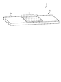
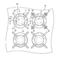
- FIG. 1 is a diagram showing a configuration example of a storage container according to the first embodiment of the present invention.
- FIG. 2 is a diagram showing a configuration example of a storage well of the storage container according to the first embodiment of the present invention.
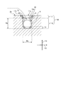
- FIG. 3 is a schematic cross-sectional view schematically showing the configuration of the storage well shown in FIG. 2 taken along the line AA.
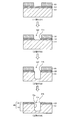
- FIG. 4 is a diagram showing an example of a method of manufacturing the storage well according to the first embodiment of the present invention.
- FIG. 5 is a figure which shows one structural example of the storage well of the storage container which concerns on Embodiment 2 of this invention.
- FIG. 6 is a schematic sectional view schematically showing the configuration of the storage well shown in FIG. 5 taken along the line BB.
- FIG. 7 is a diagram showing an example of a method of manufacturing a storage well according to the second embodiment of the present invention.
- FIG. 8 is a figure which shows one structural example of the storage well of the storage container which concerns on Embodiment 3 of this invention.
- FIG. 9 is a schematic cross-sectional view schematically showing the structure of the storage well shown in FIG. 8 taken along the line CC.
- FIG. 10 is a figure which shows one structural example of the storage well which concerns on the modification 1 of Embodiment 3 of this invention.
- FIG. 11 is a diagram showing a configuration example of the storage well according to the second modification of the third embodiment of the present invention.
- FIG. 12 is a diagram showing a configuration example of a storage well of a storage container according to the fourth embodiment of the present invention.
- FIG. 13 is a diagram showing an example of a method of manufacturing a storage well according to the fourth embodiment of the present invention.
- FIG. 1 is a diagram showing a configuration example of a storage container according to the first embodiment of the present invention.
- the storage container 1 according to the first embodiment is a container for storing a microscopic substance to be stored such as cells, and as shown in FIG. 1, a substrate having a storage well group 5 formed on a predetermined substrate surface 2a. It consists of two.
- the substrate 2 is, for example, a glass substrate made of a glass material such as quartz glass (SiO 2 ).
- the storage well group 5 is composed of a plurality of storage wells that store the objects to be stored.
- the plurality of storage wells are formed on a predetermined substrate surface 2a (upper surface in FIG. 1) of the substrate 2 so as to be arranged in a predetermined pattern such as a lattice pattern.
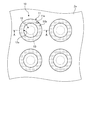
- FIG. 2 is a diagram showing a configuration example of a storage well of the storage container according to the first embodiment of the present invention.
- FIG. 2 illustrates a part of the storage wells extracted from the storage well group 5 of the storage container 1 according to the first embodiment as viewed from the opening side (top view).
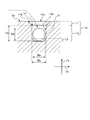
- FIG. 3 is a schematic cross-sectional view schematically showing the configuration of the storage well shown in FIG. 2 taken along the line AA.
- the depth direction of the storage well is defined as the depth direction F1 as shown in FIG. 3, for example.
- the opening side of the storage well (the substrate surface 2a side) is the upper side
- the bottom side of the storage well (the side opposite to the substrate surface 2a) is the lower side.
- a direction perpendicular to the depth direction F1 of the storage well is defined as a width direction F2, as shown in FIG. 3, for example.
- the width direction F2 for convenience of description, the right side is the positive side and the left side is the negative side in the drawing.
- the storage well 10 stores an opening forming portion 11 that forms an opening of the storage well 10 and an object 9 to be stored in and out through the opening.
- a storage unit 12 for storing the data.
- the opening forming portion 11 and the storage portion 12 are made of the same glass material (for example, quartz glass).
- the opening forming part 11 constitutes an upper part of the storage well 10 in the depth direction F1 with respect to the storage part 12. More specifically, as shown in FIGS. 2 and 3, the opening forming part 11 forms an opening 11 a that opens to the substrate surface 2 a as the opening of the storage well 10. Further, the opening forming portion 11 has an inclined surface 11b on the inner wall of the opening portion 11a. As shown in FIG. 3, the inclined surface 11b is a surface inclined from the substrate surface 2a to the lower side of the storage well 10 in the depth direction F1. In the first embodiment, the inclined surface 11b is formed around the entire inner wall of the opening 11a.
- the dimension of the opening 11a in the width direction F2 continuously decreases from the substrate surface 2a toward the lower side of the storage well 10 in the depth direction F1.
- Examples of the shape of the opening 11a include an inverted truncated cone shape and an inverted truncated pyramid shape. 2 and 3 show an inverted truncated cone shape as an example of the shape of the opening 11a.
- the inverted truncated cone shape is a shape in which the truncated cone is turned upside down.
- the inverted truncated pyramid shape is a shape in which the truncated pyramid is turned upside down.
- the storage portion 12 is a bottomed concave portion that communicates with an area on the substrate surface 2a through the opening 11a. More specifically, as shown in FIGS. 2 and 3, the storage portion 12 is below the opening forming portion 11 in the depth direction F1 of the storage well 10 and covers the side wall surface 12a over the entire inner circumference of the storage portion 12. Have.
- the side wall surface 12a is formed so as to extend in a direction perpendicular to the substrate surface 2a. Examples of the shape of the side wall surface 12a include a cylindrical side wall shape or a prismatic side wall shape. 2 and 3, a cylindrical side wall shape is shown as an example of the shape of the side wall surface 12a.
- the storage portion 12 has a bottom portion 13 continuous with the lower end of the side wall surface 12a. For example, as shown in FIG. 3, the bottom portion 13 has an inclination at a connecting portion with the side wall surface 12a corresponding to the above-mentioned inclined surface 11b.
- the side wall surface 12a of the storage portion 12 is continuous with the inclined surface 11b of the opening 11a described above, as shown in FIGS. More specifically, the lower end of the inclined surface 11b of the opening 11a is continuous with the side wall surface 12a of the storage portion 12 by forming a ridge line 14.
- the lower end of the inclined surface 11b and the upper end of the side wall surface 12a coincide with each other at the ridge line 14, and the inclined surface 11b and the upper end of the side wall surface 12a are located between the lower end of the inclined surface 11b and the upper end of the side wall surface 12a.
- No surface other than the side wall surface 12a (for example, a horizontal plane parallel to the substrate surface 2a) is present.
- the storage unit 12 stores the stored object 9 in an internal space surrounded by the side wall surface 12 a and the bottom portion 13.
- the depth Ha and the width Wa of the storage portion 12 forming this internal space are set to dimensions suitable for individually storing the stored objects 9.
- the depth Ha of the storage portion 12 is the length in the depth direction F1 from the upper end of the side wall surface 12a of the storage portion 12 to the lower end of the bottom portion 13.
- the width Wa of the storage portion 12 is the length between the side wall surfaces 12a of the storage portion 12 that face each other in the width direction F2.
- the depth Ha of the storage unit 12 is an appropriate value such as a value satisfying the condition of Hb ⁇ Ha ⁇ 2 ⁇ Hb based on the height Hb (length in the depth direction F1) of the object 9 to be stored. Is set to.
- the width Wa of the storage portion 12 is set to an appropriate value such as a value satisfying the condition of Wb ⁇ Wa ⁇ 2 ⁇ Wb based on the width Wb (length in the width direction F2) of the storage object 9.
- the contained object 9 may be, for example, a minute object such as a cell or a particle other than a cell. Further, the shape of the stored object 9 is not limited to the spherical shape as shown in FIG. 3, and may be a desired shape.
- the object 9 is stored in the storage well 10 configured by the opening forming portion 11 and the storage portion 12 described above by the following method. Specifically, the number is larger than the number of storage wells 10 included in the storage well group 5 of the storage container 1 shown in FIG. 1 (for example, 1.5 to 2.0 times or more the number of storage wells 10 arranged). A liquid containing the substance 9 to be stored is prepared, and this liquid is caused to flow toward the storage well group 5 on the substrate surface 2a of the storage container 1. As a result, the plurality of stored objects 9 are stored together with the liquid in each of the storage well groups 5 from the substrate surface 2a. At this time, for one storage well 10, one storage object 9 passes through the opening 11a from the substrate surface 2a, goes down the inclined surface 11b, and then the storage portion 12 of the storage portion 12 as shown by the broken line arrow in FIG. It flows with the liquid inside.
- the stored object 9 once stored in the storage well 10 is restrained from flowing (moving) by the side wall surface 12a of the storing section 12. As a result, the stored object 9 becomes difficult to be detached from the storage well 10 unless the storage well 10 is intentionally taken out. Even if the cleaning step is performed to remove the extra stored object 9 remaining on the substrate surface 2a with the cleaning liquid, the stored object 9 in the storage well 10 is flushed to the outside of the storage well 10 by the cleaning liquid. It remains in the storage well 10 without being stored.
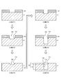
- FIG. 4 is a diagram showing an example of a method of manufacturing the storage well according to the first embodiment of the present invention.
- Each of the storage well groups 5 of the storage container 1 is formed by the same manufacturing method as the storage well 10.
- the step ST1 of patterning the resist 101 on the substrate 2 is performed.
- the resist 101 is formed on the substrate 2 by a photolithography technique so as to form a pattern exposing a portion of the substrate 2 where the storage well 10 is formed.
- a step ST2 of forming the inclined surface 11b by etching is performed on the portion of the substrate 2 which becomes the inner wall of the opening 11a of the storage well 10.
- the resist 101 described above serves as a mask, and the portion of the substrate 2 not covered with the resist 101 is wet-etched.
- the concave portion 102 having the inclined surface 11b on the inner wall is formed in the portion of the substrate 2 as shown in FIG.
- the inclined surface 11b is inclined so as to descend from the surface portion of the substrate 2 masked by the resist 101 toward the bottom surface of the concave portion 102.
- step ST3 of removing the resist 101 is performed.
- the resist 101 is removed from the substrate 2 by a predetermined resist peeling process.
- the concave portion 102 having the inclined surface 11b on the inner wall is formed on the substrate 2.
- step ST4 of patterning the resist 101 on the substrate 2 having the concave portion 102 is performed.
- the resist 101 is formed by the photolithography technique so as to form a pattern that exposes a portion of the substrate 2 excluding the inclined surface 11b (specifically, the bottom surface of the concave portion 102) of the substrate 2.
- a film is formed on 2.
- step ST5 of etching the portion of the substrate 2 other than the inclined surface 11b of the concave portion 102 is performed.
- the resist 101 obtained in the above-described step ST4 serves as a mask, and the recessed portion 102 is dry-etched except for the portion covered by the resist 101 (the inclined surface 11b and the like).
- the concave portion 102 of the substrate 2 is formed deeper while maintaining the inclined surface 11b as shown in FIG.
- step ST6 of removing the resist 101 is performed, and this processing is completed.
- the resist 101 is removed from the substrate 2 by a predetermined resist peeling process or the like.
- the storage well 10 including the opening forming portion 11 having the opening 11a and the inclined surface 11b and the bottomed storage portion 12 having the side wall surface 12a is formed on the substrate 2.
- the plurality of storage wells 10 formed on the substrate surface 2a are formed on the inner wall (for example, the entire inner wall) of the opening 11a by the opening forming portion 11 from the substrate surface 2a.
- the substrate surface has an inclined surface 11b that is inclined downward in the depth direction F1 of the storage well 10, and is below the opening forming portion 11 in the depth direction F1 of the storage well 10 via the opening 11a.
- the side wall surface 12a of the storage portion 12 extends in a direction perpendicular to the substrate surface 2a, and the lower end of the inclined surface 11b is provided. Is continuous with the side wall surface 12a of the storage portion 12 by forming a ridge line 14.
- the surface of the substrate 2a is not covered.
- the object 9 to be stored can be smoothly guided from the opening 11a to the inside of the storage 12 along the inclined surface 11b, and can be easily stored inside the storage 12.
- the flow of the object 9 to be stored once stored in the storage section 12 can be suppressed by the vertical side wall surface 12a of the storage section 12.
- unintended detachment of the object to be stored 9 from the storage well 10 can be suppressed.
- FIG. 5 is a figure which shows one structural example of the storage well of the storage container which concerns on Embodiment 2 of this invention.
- FIG. 5 shows a part of the storage wells extracted from the storage well group of the storage container according to the second embodiment as viewed from the opening side.
- FIG. 6 is a schematic sectional view schematically showing the configuration of the storage well shown in FIG. 5 taken along the line BB.
- the storage well 20 according to the second embodiment includes an opening forming portion 21 instead of the opening forming portion 11 of the storage well 10 according to the first embodiment described above, and replaces the storage portion 12. And a storage unit 22.
- the storage container according to the second embodiment is the storage well included in the storage well group 5 (see FIG. 1) on the predetermined substrate surface 2a of the substrate 2 as the storage well 10 of the first embodiment described above. Instead, the storage well 20 of the second embodiment is provided.
- Other configurations are the same as those of the first embodiment, and the same components are designated by the same reference numerals.
- the opening forming portion 21 constitutes an upper portion of the storage well 20 in the depth direction F1 with respect to the storage portion 22. More specifically, as shown in FIGS. 5 and 6, the opening forming part 21 forms an opening 21 a that opens to the substrate surface 2 a as an opening of the storage well 20. Further, the opening forming portion 21 has an inclined surface 21b on the inner wall of the opening 21a.
- the inclined surface 21b is a surface inclined from the substrate surface 2a to the lower side of the depth direction F1 of the storage well 20 as shown in FIG.
- the inclined surface 21b is formed so as to be biased to the side opposite to the later-described upper side wall surface 21c with respect to the opening center axis CL of the opening 21a. That is, the opening dimension of the opening 21a continuously decreases in the range from the upper end to the lower end of the inclined surface 21b as it goes from the substrate surface 2a to the lower side of the depth direction F1 of the storage well 20.
- such an opening 21a for example, a shape in which an inverted truncated cone shape and a columnar shape are combined so as to be eccentric to each other, or a shape in which an inverted truncated pyramid shape and a prismatic shape are combined so as to be eccentric to each other, etc.
- Is mentioned. 5 and 6 show, as an example of the shape of the opening 21a, a shape in which an inverted truncated cone shape and a columnar shape are combined so as to be eccentric to each other.
- the opening forming portion 21 has an upper side wall surface 21c above the side wall surface 12a of the storage portion 22 in the depth direction F1 of the storage well 20.
- the upper side wall surface 21c is formed in a portion of the inner wall of the opening 21a, which is biased to the side opposite to the inclined surface 21b with respect to the opening center axis CL, in a direction perpendicular to the substrate surface 2a. It is formed so as to extend.
- the upper side wall surface 21c is flush with the side wall surface 12a of the storage part 22 and is integrally continuous.
- the storage portion 22 is a bottomed concave portion that communicates with a region on the substrate surface 2a through the opening 21a and that stores the object 9 to be stored therein so that it can be taken in and out through the opening 21a. More specifically, as shown in FIGS. 5 and 6, the storage portion 22 has a side wall surface 12a similar to that of the above-described first embodiment below the opening forming portion 21 in the depth direction F1 of the storage well 20. .. Further, the storage portion 22 has a bottom portion 23 that is continuous with the lower end of the side wall surface 12a. For example, as shown in FIG. 6, the bottom portion 23 has a slope formed at the connection portion with the side wall surface 12a so as to be biased to the side opposite to the sloped surface 21b with respect to the opening center axis CL of the opening 21a.
- the side wall surface 12a of the storage portion 22 is continuous with the above-described inclined surface 21b of the opening portion 21a, as shown in FIGS. More specifically, the lower end of the inclined surface 21b of the opening 21a is continuous with the side wall surface 12a of the storage portion 22 by forming the ridge line 14 directly, and the side wall surface of the storage portion 22 via the upper side wall surface 21c. A ridge line 14 is formed indirectly with 12a and is continuous.
- the side wall surface 12a of the storage part 22 is flush with the upper side wall surface 21c and is integrally continuous, there is a gap between the lower end of the inclined surface 21b and the upper end of the side wall surface 12a.
- There is no surface other than the inclined surface 11b, the side wall surface 12a and the upper side wall surface 21c (for example, a horizontal plane parallel to the substrate surface 2a).
- the storage unit 22 stores the stored object 9 in an internal space surrounded by the side wall surface 12 a and the bottom portion 23.
- the depth Ha and the width Wa of the storage portion 22 forming this internal space are set to dimensions suitable for individually storing the articles 9 to be stored, as in the first embodiment described above.
- the object to be stored 9 is stored in the storage well 20 configured by the opening forming portion 21 and the storage portion 22 described above by the same method as in the first embodiment.
- a liquid (not shown) containing a plurality of objects to be stored 9 is caused to flow in a predetermined direction F3 (see FIG. 6) along the substrate surface 2a.
- the plurality of stored objects 9 are stored together with the liquid in each of the storage well groups 5 (see FIG. 1) from the substrate surface 2a.
- one storage object 9 passes through the opening 21a from the substrate surface 2a, goes down the inclined surface 21b, and then the storage portion 22 of the storage portion 22 as shown by the broken line arrow in FIG. It flows with the liquid inside.
- the stored object 9 once stored in the storage well 20 in this way is restrained from flowing (moving) by the side wall surface 12a and the upper side wall surface 21c of the storage part 22.
- the effect of suppressing the flow of the object 9 to be stored is improved by providing the upper side wall surface 21c above the side wall surface 12a as compared with the case of only the side wall surface 12a.
- the stored object 9 becomes more difficult to detach from the storage well 20 unless the storage well 20 is intentionally taken out.
- the cleaning step is performed to remove the extra stored object 9 on the substrate surface 2a with the cleaning liquid, the stored object 9 in the storage well 20 still contains the cleaning liquid (especially the cleaning liquid flowing in the predetermined direction F3). ) Does not flow out of the storage well 20 and remains in the storage well 20.
- FIG. 7 is a diagram showing an example of a method of manufacturing a storage well according to the second embodiment of the present invention.
- Each of the storage well groups 5 of the storage container according to the second embodiment is formed by the same manufacturing method as the storage well 20.
- a step ST11 of patterning the resist 101 on the substrate 2 is performed.
- the resist 101 is formed on the substrate 2 by a photolithography technique so as to form a pattern exposing a portion of the substrate 2 where the storage well 20 is formed.
- a step ST12 of forming the inclined surface 113 by etching on a portion of the substrate 2 which becomes the inner wall of the opening 21a of the storage well 20 is performed.
- the resist 101 described above serves as a mask, and the portion of the substrate 2 not covered with the resist 101 is wet-etched.
- the concave portion 112 having the inclined surface 113 on the inner wall is formed in the portion of the substrate 2 as shown in FIG. 7.
- the inclined surface 113 is inclined from the surface portion of the substrate 2 masked by the resist 101 toward the bottom surface of the concave portion 112.
- step ST13 of removing the resist 101 is performed.
- the resist 101 is removed from the substrate 2 by a predetermined resist peeling process.
- the concave portion 112 having the inclined surface 113 on the inner wall is formed on the substrate 2.
- step ST14 of patterning the resist 101 on the substrate 2 having the recess 112 is performed.
- the resist 101 exposes the bottom surface of the concave portion 112 and the portion on one side of the inclined surface 113 (on the right side of the paper in FIG. 7) of the substrate 2 by the photolithography technique and the other portion ( A film is formed on the substrate 2 so as to form a pattern that covers the other surface of the inclined surface 113).
- a step ST15 of etching an exposed portion such as the concave portion 102 of the substrate 2 is performed.
- the resist 101 obtained in the above-mentioned step ST14 serves as a mask, and a portion of the concave portion 112 other than the portion covered with the resist 101 (the portion on the left side of the inclined surface 113 in FIG. 7) is dry-etched. It As a result, the concave portion 112 of the substrate 2 is formed deeper while maintaining the masked portion of the inclined surface 113, as shown in FIG. 7.
- step ST16 of removing the resist 101 is performed, and this processing is completed.
- step ST16 the resist 101 is removed from the substrate 2 by a predetermined resist peeling process or the like.
- the storage well 20 including the opening forming portion 21 having the opening portion 21a, the inclined surface 21b and the upper side wall surface 21c and the bottomed storing portion 22 having the side wall surface 12a is provided in the storage well 20. Is formed.
- the depth direction F1 of the storage well 20 is smaller than the side wall surface 12a of the storage portion 22.
- An upper side wall surface 21c extending in a direction perpendicular to the substrate surface 2a is formed in the upper portion, and is biased to the side opposite to the upper side wall surface 21c with respect to the opening center axis CL of the opening 21a.
- An inclined surface 21b that inclines downward from the substrate surface 2a in the depth direction F1 of the storage well 20 is formed in the portion, and the other configurations are similar to those of the first embodiment.
- FIG. 8 is a figure which shows one structural example of the storage well of the storage container which concerns on Embodiment 3 of this invention.
- FIG. 8 shows a part of the storage wells extracted from the storage well group of the storage container according to the third embodiment as viewed from the opening side.
- FIG. 9 is a schematic cross-sectional view schematically showing the structure of the storage well shown in FIG. 8 taken along the line CC.
- the storage well 30 according to the third embodiment further includes a liquid outflow portion 35 in addition to the same configuration as the storage well 10 according to the first embodiment described above.
- the storage container according to the third embodiment is a storage well included in the storage well group 5 (see FIG. 1) on the predetermined substrate surface 2a of the substrate 2 in the storage well 10 of the first embodiment. Instead, the storage well 30 of the third embodiment is provided.
- Other configurations are the same as those of the first embodiment, and the same components are designated by the same reference numerals.
- the liquid outflow portion 35 is for releasing the liquid accumulated inside the storage well 30 to the outside. More specifically, as shown in FIGS. 8 and 9, the liquid outflow portion 35 forms a space having a slit shape in cross section having a depth from the substrate surface 2 a to the bottom portion 13 of the storage portion 12, and the storage portion of the storage well 30.
- the substrate 2 (see FIG. 1) is provided with a desired number so as to extend from 12 to a portion outside the opening 11a.
- the plurality of liquid outflow portions 35 (four in FIG. 8) are provided at predetermined intervals around the central axis of the storage well 30 in the depth direction F1.
- the depth of the liquid outflow portion 35 (the distance between the upper end and the lower end in the depth direction F1) is the same as that of the storage well 30.
- the storage 12 side, the inner wall side of the opening 11a (that is, the inclined surface 11b side), and the substrate surface 2a side of the liquid outflow portion 35 are continuous with each other and open.
- the opening size of each opening of the liquid outflow portion 35 is smaller than the size (width, height, etc.) of the stored object 9.
- Such a liquid outflow portion 35 communicates with the storage portion 12 of the storage well 30 and allows the liquid that has flowed into the storage portion 12 through the opening 11 a to flow out of the storage portion 12. Further, the stored object 9 cannot flow into the liquid outflow portion 35.
- the liquid outflow portion 35 described above is formed by patterning the resist 101 so as to expose a portion of the substrate 2 where the liquid outflow portion 35 is formed, and the portion is recessed. It can be formed by etching together with 102.
- the object 9 is stored in the storage well 30 according to the third embodiment by the same method as in the first embodiment.
- a liquid (not shown) containing a plurality of objects 9 to be stored is flown onto the substrate surface 2a toward the storage well group 5 (see FIG. 1).
- the plurality of stored objects 9 are stored together with the liquid in each of the storage well groups 5 from the substrate surface 2a.
- one storage object 9 passes through the opening 11a from the substrate surface 2a, goes down the inclined surface 11b, and then the storage portion 12 of the storage portion 12, as shown by the broken line arrow in FIG. It flows with the liquid inside.
- the stored object 9 once stored in the storage well 30 is prevented from flowing (moving) by the side wall surface 12a of the storage section 12 as in the case of the first embodiment described above, and thus the storage well 30 is stored. Unless it is intentionally taken out from the storage well 30, it becomes difficult to detach from the storage well 30. Even if a cleaning process is performed to remove the excess stored object 9 on the substrate surface 2a with a cleaning liquid, the stored object 9 in the storage well 30 is flushed to the outside of the storage well 30 by the cleaning liquid. It remains in the storage well 30 without being stored.
- the liquid for pouring the object to be stored 9 into the storage well 30 (in particular, the inside of the storage part 12) is stored before the object to be stored 9. There is a case where it flows in and is filled. If the object to be stored 9 is stored in a storage well that does not include the liquid outflow portion 35 described above, in order to allow the object to be stored 9 to flow into the storage well already filled with the liquid, the side of the storage well is required. It is necessary to let the liquid flow out through the gap between the wall surface and the outer surface of the object to be stored 9. In this case, since the gap is extremely small (for example, a dimension on the order of micron), it may be difficult to allow the stored object 9 to flow into the storage well while causing the liquid to flow to the outside. ..
- the stored object 9 flows from the opening 11 a toward the inside of the storage portion 12 and the liquid filling the inside of the storage portion 12 is filled.
- 8 flows out from the inside of the storage section 12 through the inside of the liquid outflow section 35 to the substrate surface 2a outside the storage well 30, as shown by the double-dashed line arrow in FIGS. This makes it difficult for the liquid in the storage section 12 to block the inflow (storage) of the object 9 to be stored into the storage section 12.
- the liquid outflow portion 35 that communicates with the storage portion 12 of the storage well 30 is provided, and the liquid that has flowed into the storage portion 12 is transferred from the liquid outflow portion 35 to the outside of the storage portion 12.
- the other parts are configured similarly to the first embodiment. For this reason, while enjoying the same operation and effect as in the case of the above-described first embodiment, the liquid stored in the storage portion 12 is caused to flow out from the liquid outflow portion 35 to the outside, and the storage portion 12 is opened from the opening portion 11a.
- the object 9 can be flown into the inside. As a result, since the inflow of the stored object 9 into the storage section 12 is less likely to be hindered by the liquid, even if the storage section 12 is filled with the liquid, the stored object is stored in the storage section 12. 9 can be easily stored.
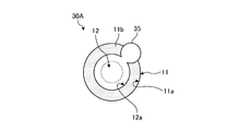
- FIG. 10 is a figure which shows one structural example of the storage well which concerns on the modification 1 of Embodiment 3 of this invention.
- FIG. 10 shows the storage well 30A according to the first modification as viewed from the opening side thereof.
- the liquid outflow portion 35 described above is not limited to the one that forms the space having the slit shape in cross section shown in FIGS. 8 and 9, and may have another shape.
- the storage well 30A according to the present first modification includes a liquid outflow portion 35 that forms a cylindrical space.
- the liquid outflow portion 35 in Modification 1 is opened over the entire depth direction of the storage portion 12 in a part of the side wall surface 12a, and communicates with the storage portion 12 through this opening. Further, the upper end of the liquid outflow portion 35 opens over the range from the inclined surface 11b of the opening forming portion 11 to the outside of the opening 11a, and communicates from the opening to the outside of the storage well 30A.
- Such a liquid outflow portion 35 has the same opening size with the storage portion 12 as that of the above-described slit-shaped cross section, but has the volume of the internal space communicating with the storage portion 12 of the above-described slit-shaped cross section. It can be larger than the volume.
- the liquid that has flowed into the storage section 12 can be caused to flow out of the storage section 12 from the liquid outflow section 35, and therefore the same effect as that of the above-described third embodiment.
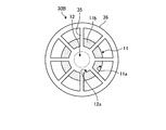
- FIG. 11 is a diagram showing a configuration example of the storage well according to the second modification of the third embodiment of the present invention.
- FIG. 11 shows the storage well 30B according to the second modification as viewed from the opening side thereof.
- the number of the liquid outflow portions 35 described above is not limited to four as shown in FIG. 8, and even if each of the plurality of liquid outflow portions 35 communicates with each other at their outer ends or the like. Good.
- the storage well 30B according to the second modification includes a plurality (eight in FIG. 11) of liquid outflow portions 35 having the same configuration as the third embodiment, and a plurality of these liquid outflow portions.
- an annular groove portion 36 that communicates the outer ends of each other with each other.
- the annular groove portion 36 is an example of a groove portion that communicates with each of the plurality of liquid outflow portions 35.
- the annular groove portion 36 is an annular bottomed groove portion that surrounds the opening forming portion 11 and the storage portion 12, and opens to the substrate surface 2a (see FIG. 8) side, and the storage well 30B is opened from this opening. Communicates to the outside. Further, the annular groove portion 36 has an opening at each portion corresponding to each outer end of the plurality of liquid outflow portions 35, and communicates with the plurality of liquid outflow portions 35 through these openings. Such an annular groove portion 36 can increase the total volume of the plurality of liquid outflow portions 35 while maintaining the size and shape of each liquid outflow portion 35.
- the liquid that has flowed into the storage portion 12 can be caused to flow out of the storage portion 12 from the plurality of liquid outflow portions 35 and the annular groove portion 36, and therefore, in the above-described third embodiment.
- the liquid that has flowed into the storage portion 12 can be caused to flow out of the storage portion 12 from the plurality of liquid outflow portions 35 and the annular groove portion 36, and therefore, in the above-described third embodiment.
- FIG. 12 is a diagram showing a configuration example of a storage well of a storage container according to the fourth embodiment of the present invention.
- FIG. 12 shows a side cross section of a part of the storage wells extracted from the storage well group of the storage container according to the fourth embodiment.
- the storage well 40 according to the fourth embodiment includes an opening formation portion 41 instead of the opening formation portion 11 of the storage well 10 according to the first embodiment described above.
- the storage container according to the fourth embodiment is a storage well included in the storage well group 5 (see FIG. 1) on the predetermined substrate surface 2a of the substrate 2 and is the same as the storage well 10 of the first embodiment.
- the storage well 40 of the fourth embodiment is provided.
- Other configurations are the same as those of the first embodiment, and the same components are designated by the same reference numerals.
- the opening forming part 41 is made of a glass material different from that of the storage part 12.
- the storage unit 12 is made of pure quartz glass.
- pure quartz glass refers to quartz glass in which the concentration of impurities that are unintentionally included is 0.1 mol% or less.
- the concentration of the impurities intentionally added in the pure quartz glass is 1.0 mol% or more and 25 mol% or less.
- the opening forming portion 41 is made of quartz glass to which a predetermined additive material is added, for example, quartz glass to which zirconia (ZrO 2 ) is added (hereinafter, appropriately referred to as zirconia-added glass).
- the addition rate (content rate) of zirconia in the zirconia-added glass forming the opening forming portion 41 is several mol% or less with respect to the mass or volume of the entire target quartz glass.
- the opening forming part 41 is the same as the opening forming part 11 in the above-described first embodiment except that the material of the opening forming part 41 is different from that of the housing part 12 as described above, and as shown in FIG. 11a is formed and an inclined surface 11b is provided on the inner wall of the opening 11a.
- zirconia for example, hafnia (HfO 2 ), alumina (Al 2 O 3 ), and the like can be cited as the additive material of the quartz glass forming the opening forming portion 41, and zirconia is particularly preferable.
- the substrate 2 (see FIG. 1) in which a plurality of storage wells 40 having the storage portion 12 and the opening forming portion 41, which are made of different materials from each other, are formed as one of the storage well groups 5 as described above, It is a laminated substrate in which a glass film made of zirconia-added glass (zirconia-added glass film) is formed on a glass substrate made of a glass material such as quartz glass. That is, in the fourth embodiment, the substrate surface 2a shown in FIG. 12 is the surface of the zirconia-added glass film in which the opening forming portion 41 is provided.
- FIG. 13 is a diagram showing an example of a method of manufacturing a storage well according to the fourth embodiment of the present invention.
- Each of the storage well groups 5 of the storage container according to the fourth embodiment is formed by the same manufacturing method as the storage well 40.
- a zirconia-added glass is exemplified as the quartz glass forming the opening forming portion 41, and the method for manufacturing the storage well according to the fourth embodiment will be described.
- the additive material of the quartz glass is The same applies to cases other than zirconia (for example, hafnia and alumina).
- a step ST21 of patterning the resist 101 on the surface of the zirconia-added glass film 122 formed on the glass substrate 121 made of pure quartz glass is performed.
- the resist 101 is formed on the zirconia-added glass film 122 by photolithography so as to form a pattern that exposes a portion of the zirconia-added glass film 122 where the storage well 40 is formed.
- step ST22 of etching the zirconia-added glass film 122 in the pattern of the resist 101 is performed.
- the resist 101 obtained in step ST21 serves as a mask, and the portion of the zirconia-added glass film 122 not covered with the resist 101 is dry-etched.
- the concave portion 102 having the inclined surface 11b on the inner wall is formed in the portion of the zirconia-added glass film 122 as shown in FIG.
- the inclined surface 11b is inclined from the surface portion of the zirconia-added glass film 122 masked by the resist 101 toward the bottom surface of the concave portion 102.
- the concave portion 102 has the bottom surface as the exposed surface of the glass substrate 121 exposed by the dry etching of the zirconia-added glass film 122.
- the etching rate of the exposed portion is from the center side of the exposed portion to the mask side (depending on the resist 101). It tends to be slower as it gets closer to the coated side. That is, the zirconia-added glass film 122 is characterized in that it is easy to form an inclined surface that descends from the mask side toward the center side during dry etching. Therefore, in the exposed portion of the zirconia-added glass film 122, the etching depth of the central portion is increased by dry etching, and the inclined surface 11b (see FIG. 13) of the above-described aspect is provided in the mask side portion. It is formed.
- the step ST23 of etching the above-mentioned concave portion 102 is performed.
- the resist 101 described above continues to serve as a mask, and the portions of the glass substrate 121 and the zirconia-added glass film 122 that are exposed in a pattern from the resist 101, that is, the concave portions 102 formed in step ST22 are further dry-etched. To be done.
- the concave portion 102 is formed deeper by increasing the etching depth of the glass substrate 121 while leaving the inclined surface 11b in the portion of the zirconia-added glass film 122.
- the above-mentioned steps ST22 and ST23 are both dry etching using the resist 101 having the same pattern as a mask, and therefore are continuously performed by one dry etching.
- step ST24 of removing the resist 101 is performed, and this processing is completed.
- the resist 101 is removed from the zirconia-added glass film 122 by a predetermined resist peeling process or the like.
- the opening forming portion 41 having the opening 11a and the inclined surface 11b in the portion of the zirconia-added glass film 122, and the bottomed storage portion 12 having the side wall surface 12a in the portion of the glass substrate 121.
- the storage well 40 is formed on the substrate (the laminated substrate of the glass substrate 121 and the zirconia-added glass film 122).
- the opening forming portion 41 having the opening 11a opening to the substrate surface 2a and the inclined surface 11b inclined downward from the substrate surface 2a in the depth direction F1 is provided.
- Zirconia, and other additive materials are used to form the quartz glass, and the others are configured similarly to the first embodiment.
- the opening 11a, the inclined surface 11b, and the storage portion 12 of the storage well 40 can be continuously formed by one dry etching. From the manufacturing process of the well 40, the wet etching process for forming the opening and the inclined surface and the resist film forming process and the removing process for performing this wet etching can be omitted. As a result, the storage well 40 The storage well 40 can be easily formed by reducing the labor required for manufacturing the storage well 40.
- the storage well including the opening and the storage portion whose top view shape (the shape viewed from the opening side) is circular is illustrated, but the present invention is not limited to this. Not something.
- the shape of the opening of the storage well and the storage section in a top view may be a desired shape, such as a circular shape, an elliptical shape, or a polygonal shape, in accordance with the shape or application of the stored object.
- the shapes of the openings and the storage section when viewed from above may be the same as each other or different from each other.
- the material of the opening forming portion 21 having the opening 21a, the inclined surface 21b, and the upper side wall surface 21c is the same as the material of the storage portion 22 (for example, quartz glass). It is not limited to this.
- the material of the opening forming portion 21 may be quartz glass to which an additive material such as zirconia is added, as in the case of the above-described fourth embodiment, and may be different from the material of the storage portion 22.
- the liquid outflow portion communicating with the storage portion of the storage well in which the inclined surface is formed over the entire circumference of the inner wall of the opening is illustrated.
- the liquid outflow portion may communicate with the storage portion of the storage well in which the inclined surface and the upper side wall surface are formed on the inner wall of the opening, and is made of zirconia-added quartz glass. It may be in communication with the storage portion of the storage well having the opening forming portion. That is, the storage well according to the present invention may be a combination of the first embodiment and the third embodiment and the first and second modifications as appropriate, or the second embodiment and the third embodiment and the first and second modifications. May be appropriately combined, or the fourth embodiment, the third embodiment, and the modified examples 1 and 2 may be appropriately combined.
- the case where the outer ends of the plurality of liquid outflow portions 35 are communicated with each other by the annular groove portion 36 is illustrated, but the present invention is not limited to this.
- the plurality of liquid outflow portions 35 may be communicated with each other by the annular groove portion 36 at a midway portion between the opening forming portion 11 side and the outer end.
- the groove portion that communicates with each of the plurality of liquid outflow portions 35 may not have an annular shape, and the plurality of liquid outflow portions 35 that communicate with each other by the groove portion are not limited to those that form a space having a slit-shaped cross section. Instead, for example, it may be one that forms a cylindrical space as shown in FIG.
- the present invention is not limited to the above embodiment.
- the present invention also includes those configured by appropriately combining the above-described components. Further, further effects and modified examples can be easily derived by those skilled in the art. Therefore, the broader aspects of the present invention are not limited to the above embodiments, and various modifications can be made.
- the storage container according to the present invention is suitable for a storage container capable of suppressing the damage of the stored object during storage and improving the storage efficiency of the stored object in the plurality of storage wells. There is.
Landscapes
- Chemical & Material Sciences (AREA)
- Health & Medical Sciences (AREA)
- Analytical Chemistry (AREA)
- General Health & Medical Sciences (AREA)
- Bioinformatics & Cheminformatics (AREA)
- Life Sciences & Earth Sciences (AREA)
- Engineering & Computer Science (AREA)
- Chemical Kinetics & Catalysis (AREA)
- Clinical Laboratory Science (AREA)
- Hematology (AREA)
- Biotechnology (AREA)
- Wood Science & Technology (AREA)
- Zoology (AREA)
- Organic Chemistry (AREA)
- Microbiology (AREA)
- General Engineering & Computer Science (AREA)
- Genetics & Genomics (AREA)
- Biochemistry (AREA)
- Sustainable Development (AREA)
- Biomedical Technology (AREA)
- Medicinal Chemistry (AREA)
- Apparatus Associated With Microorganisms And Enzymes (AREA)
Abstract
格納容器は、被格納物を格納する格納ウェルが所定の基板表面に複数形成された基板からなる。前記格納ウェルは、前記基板表面に開口する開口部を形成し、前記開口部の内壁に、前記基板表面から前記格納ウェルの深さ方向下側に傾斜する傾斜面を有する開口形成部と、前記開口形成部よりも前記格納ウェルの深さ方向下側に、前記基板表面に対して垂直な方向に延在する側壁面を有し、前記開口部を介して前記基板表面上の領域と通じる有底の格納部と、を備えている。前記傾斜面の下端は、前記格納部の前記側壁面と稜線を形成して連続している。
Description
本発明は、格納容器に関するものである。
従来、細胞等の微細な被格納物を個別に格納するためのウェル(格納ウェル)を複数備える格納容器が知られている。例えば、対象とする被格納物が細胞である場合、格納ウェルの配置数に比べて1.5~2.0倍以上の数の細胞を含んだ液体(懸濁液)が格納容器の表面に流され、これにより、複数の格納ウェルの各々に細胞が液体とともに投入される。このような格納ウェルとして、例えば、特許文献1には、逆角錐形の開口部と円筒形の有底穴とを組み合わせた形状のマイクロウェルが開示されている。また、特許文献2には、イムノチャンバーに複数形成された逆錐台形のウェルが開示されている。
しかしながら、上述した特許文献1に記載される従来の格納ウェルでは、格納した細胞から分泌される抗体を載せるための平坦面が開口部の傾斜面とウェル側壁面との間に存在するので、細胞等の被格納物をウェル内に流し入れる際、この平坦面と側壁面とが繋がる角部に被格納物が接触して傷つく恐れがある。
また、上述した特許文献2に記載される従来の格納ウェルでは、ウェル内壁面が開口端から底面に向かって下方に傾斜しているので、被格納物をウェル内へ流し入れやすい反面、一旦ウェル内に格納された被格納物が、液体の流れ等に伴ってウェル内から意図せず脱離する恐れがある。これに起因して、複数の格納ウェルの各々に被格納物が格納される確率、すなわち、格納容器に設けられている全ての格納ウェルのうち、被格納物が格納されている格納ウェルの割合(以下、格納効率という)が低下する場合がある。
本発明は、上記事情に鑑みてなされたものであって、格納の際に被格納物が傷つくことを抑制するとともに、複数の格納ウェルにおける被格納物の格納効率を向上させることができる格納容器を提供することを目的とする。
上述した課題を解決し、目的を達成するために、本発明に係る格納容器は、被格納物を格納する格納ウェルが所定の基板表面に複数形成された基板からなる格納容器であって、前記格納ウェルは、前記基板表面に開口する開口部を形成し、前記開口部の内壁に、前記基板表面から前記格納ウェルの深さ方向下側に傾斜する傾斜面を有する開口形成部と、前記開口形成部よりも前記格納ウェルの深さ方向下側に、前記基板表面に対して垂直な方向に延在する側壁面を有し、前記開口部を介して前記基板表面上の領域と通じる有底の格納部と、を備え、前記傾斜面の下端は、前記格納部の前記側壁面と稜線を形成して連続することを特徴とする。
また、本発明に係る格納容器は、上記の発明において、前記傾斜面は、前記開口部の内壁全周に亘って形成されることを特徴とする。
また、本発明に係る格納容器は、上記の発明において、前記開口形成部は、前記格納部の側壁面よりも前記格納ウェルの深さ方向上側に、前記基板表面に対して垂直な方向に延在する上部側壁面を有し、前記傾斜面は、前記開口部の開口中心軸に対して前記上部側壁面とは反対側に偏って形成されることを特徴とする。
また、本発明に係る格納容器は、上記の発明において、前記格納部と連通し、前記格納部に流入した液体を前記格納部の外部に流出させる液体流出部をさらに備えることを特徴とする。
また、本発明に係る格納容器は、上記の発明において、前記液体流出部の深さは、前記格納ウェルと同じ深さであることを特徴とする。
また、本発明に係る格納容器は、上記の発明において、前記液体流出部は、断面スリット状または円柱状の空間を形成するように設けられていることを特徴とする。
また、本発明に係る格納容器は、上記の発明において、複数の前記液体流出部と、複数の前記液体流出部をそれぞれ連通する溝部と、を備えることを特徴とする。
また、本発明に係る格納容器は、上記の発明において、前記開口形成部は、ジルコニアが添加された石英ガラスからなり、前記格納部は、意図せず含まれる不純物の濃度が0.1mol%以下である純石英ガラスからなることを特徴とする。
本発明によれば、格納の際に被格納物が傷つくことを抑制するとともに、複数の格納ウェルにおける被格納物の格納効率を向上させることができるという効果を奏する。
以下に、図面を参照して本発明に係る格納容器の好適な実施形態を詳細に説明する。なお、本実施形態により本発明が限定されるものではない。また、各図面において、同一または対応する要素には適宜同一の符号を付している。さらに、図面は模式的なものであり、各要素の寸法の関係などは、現実のものとは異なる場合があることに留意する必要がある。図面の相互間においても、互いの寸法の関係や比率が異なる部分が含まれている場合がある。
(実施形態1)
本発明の実施形態1に係る格納容器について説明する。図1は、本発明の実施形態1に係る格納容器の一構成例を示す図である。本実施形態1に係る格納容器1は、細胞等の微細な被格納物を格納するための容器であり、図1に示すように、所定の基板表面2aに格納ウェル群5が形成された基板2からなる。基板2は、例えば、石英ガラス(SiO2)等のガラス材からなるガラス基板である。格納ウェル群5は、被格納物を格納する複数の格納ウェルからなる。これら複数の格納ウェルは、基板2における所定の基板表面2a(図1では上面)に、格子状等の所定のパターンに配列されるよう形成されている。
本発明の実施形態1に係る格納容器について説明する。図1は、本発明の実施形態1に係る格納容器の一構成例を示す図である。本実施形態1に係る格納容器1は、細胞等の微細な被格納物を格納するための容器であり、図1に示すように、所定の基板表面2aに格納ウェル群5が形成された基板2からなる。基板2は、例えば、石英ガラス(SiO2)等のガラス材からなるガラス基板である。格納ウェル群5は、被格納物を格納する複数の格納ウェルからなる。これら複数の格納ウェルは、基板2における所定の基板表面2a(図1では上面)に、格子状等の所定のパターンに配列されるよう形成されている。
図2は、本発明の実施形態1に係る格納容器の格納ウェルの一構成例を示す図である。図2には、本実施形態1に係る格納容器1の格納ウェル群5から抜き出した一部の格納ウェルをその開口側から見たもの(上視図)が図示されている。図3は、図2に示す格納ウェルのA-A線断面の構成を模式的に示す断面模式図である。
本発明においては、格納ウェルの深さ方向が、例えば図3に示すように、深さ方向F1として定義される。深さ方向F1では、格納ウェルの開口側(基板表面2a側)が上側であり、格納ウェルの底側(基板表面2aとは反対側)が下側である。また、格納ウェルの深さ方向F1に対して垂直な方向が、例えば図3に示すように、幅方向F2として定義される。幅方向F2については、説明の便宜上、図面に向かって右側が正側とし、左側が負側としている。
図2、3に示すように、本実施形態1に係る格納ウェル10は、格納ウェル10の開口部を形成する開口形成部11と、この開口部を介して被格納物9を出し入れ可能に格納する格納部12とを備える。本実施形態1において、開口形成部11および格納部12は、互いに同じガラス材(例えば石英ガラス)からなる。
開口形成部11は、格納ウェル10のうち、格納部12よりも深さ方向F1の上側部分を構成する。詳細には、図2、3に示すように、開口形成部11は、格納ウェル10の開口部として、基板表面2aに開口する開口部11aを形成する。また、開口形成部11は、開口部11aの内壁に傾斜面11bを有する。傾斜面11bは、図3に示すように、基板表面2aから格納ウェル10の深さ方向F1の下側に傾斜する面である。本実施形態1において、傾斜面11bは、開口部11aの内壁全周に亘って形成されている。すなわち、開口部11aの幅方向F2の寸法(以下、開口寸法と適宜いう)は、基板表面2aから格納ウェル10の深さ方向F1の下側に向かうに伴って連続的に減少する。このような開口部11aの形状として、例えば、逆円錐台形状または逆角錐台形状等が挙げられる。図2、3には、開口部11aの形状の一例として、逆円錐台形状が示されている。なお、逆円錐台形状とは、円錐台の上下を逆にした形状である。同様に、逆角錐台形状とは、角錐台の上下を逆にした形状である。
格納部12は、開口部11aを介して基板表面2a上の領域と通じる有底の凹状部分である。詳細には、図2、3に示すように、格納部12は、開口形成部11よりも格納ウェル10の深さ方向F1の下側に、格納部12の内周全域に亘って側壁面12aを有する。側壁面12aは、基板表面2aに対して垂直な方向に延在するように形成されている。側壁面12aの形状として、例えば、円柱側壁状の形状または角柱側壁状の形状等が挙げられる。図2、3には、側壁面12aの形状の一例として、円柱側壁状の形状が示されている。また、格納部12は、側壁面12aの下端に連続する底部13を有する。底部13は、例えば図3に示すように、上述した傾斜面11bに対応して、側壁面12aとの接続部分に傾斜を有する。
また、格納部12の側壁面12aは、図2、3に示すように、上述した開口部11aの傾斜面11bと連続している。詳細には、開口部11aの傾斜面11bの下端は、格納部12の側壁面12aと稜線14を形成して連続している。本実施形態1において、傾斜面11bの下端と側壁面12aの上端とは稜線14で一致しており、傾斜面11bの下端と側壁面12aの上端との間には、これらの傾斜面11bおよび側壁面12a以外の面(例えば基板表面2aに平行な水平面等)は存在していない。
また、図3に示すように、格納部12は、側壁面12aおよび底部13によって囲まれる内部空間に、被格納物9を格納する。この内部空間を形成する格納部12の深さHaおよび幅Waは、被格納物9を個別に格納するに適した寸法に設定される。格納部12の深さHaは、格納部12の側壁面12aの上端から底部13の下端までの深さ方向F1の長さである。格納部12の幅Waは、格納部12の幅方向F2に対向する側壁面12a間の長さである。例えば、格納部12の深さHaは、被格納物9の高さHb(深さ方向F1の長さ)をもとに、Hb<Ha<2×Hbの条件を満たす値等、適切な値に設定される。格納部12の幅Waは、被格納物9の幅Wb(幅方向F2の長さ)をもとに、Wb<Wa<2×Wbの条件を満たす値等、適切な値に設定される。
なお、被格納物9としては、例えば、細胞や細胞以外の粒子等、微細なものが挙げられる。また、被格納物9の形状は、図3に示すような球形状に限定されず、所望の形状であってもよい。
上述した開口形成部11および格納部12によって構成される格納ウェル10には、以下に示す手法によって被格納物9が格納される。具体的には、図1に示した格納容器1の格納ウェル群5に含まれる格納ウェル10の配置数よりも多い数(例えば格納ウェル10の配置数の1.5~2.0倍以上)の被格納物9を含んだ液体を準備し、この液体が、格納ウェル群5に向けて格納容器1の基板表面2aに流される。これにより、複数の被格納物9は、基板表面2aから格納ウェル群5の各々に液体とともに格納される。この際、1つの格納ウェル10について、1つの被格納物9が、図3の破線矢印に示されるように、基板表面2aから開口部11aを通り、傾斜面11bを下って、格納部12の内部に液体とともに流れ込む。
このように格納ウェル10に一旦格納された被格納物9は、格納部12の側壁面12aによって流れ(動き)を抑止される。この結果、被格納物9は、格納ウェル10から意図的に取り出そうとしない限り、格納ウェル10から脱離し難くなる。たとえ、基板表面2a上に余分に残った被格納物9を洗浄液によって除去する洗浄工程が行われたとしても、格納ウェル10内の被格納物9は、この洗浄液によって格納ウェル10の外部に流されることなく、格納ウェル10内に留まる。
つぎに、本発明の実施形態1に係る格納ウェル10の製造方法について説明する。図4は、本発明の実施形態1に係る格納ウェルの製造方法の一例を示す図である。格納容器1の格納ウェル群5の各々は、この格納ウェル10と同様の製造方法によって形成される。
図4に示すように、格納ウェル10の製造方法では、まず、基板2上にレジスト101をパターニングする工程ST1が行われる。この工程ST1において、レジスト101は、フォトリソグラフィ技術により、基板2のうち格納ウェル10が形成される部分を露出させるパターンをなすように、基板2上に成膜される。
工程ST1を実行後、基板2のうち格納ウェル10の開口部11aの内壁となる部分に、エッチングによって傾斜面11bを形成する工程ST2が行われる。この工程ST2においては、上述したレジスト101がマスクとなり、基板2のうちレジスト101で覆われていない部分がウェットエッチングされる。これにより、基板2の当該部分には、図4に示すように、内壁に傾斜面11bを有する凹状部102が形成される。この傾斜面11bは、基板2のうちレジスト101にマスクされた表面部分から凹状部102の底面に向かって下るように傾斜している。
工程ST2を実行後、レジスト101を除去する工程ST3が行われる。この工程ST3において、レジスト101は、所定のレジスト剥離処理により、基板2上から除去される。これにより、基板2には、内壁に傾斜面11bを有する凹状部102が形成される。
工程ST3を実行後、凹状部102を有する基板2上にレジスト101をパターニングする工程ST4が行われる。この工程ST4において、レジスト101は、フォトリソグラフィ技術により、基板2のうち、凹状部102の傾斜面11bを除く部分(具体的には凹状部102の底面)を露出させるパターンをなすように、基板2上に成膜される。
工程ST4を実行後、基板2のうち凹状部102の傾斜面11b以外の部分をエッチングする工程ST5が行われる。この工程ST5においては、上述した工程ST4によるレジスト101がマスクとなり、凹状部102のうちレジスト101で覆われた部分(傾斜面11b等)以外の部分がドライエッチングされる。これにより、基板2の凹状部102は、図4に示すように、傾斜面11bを維持して更に深く形成される。
工程ST5を実行後、レジスト101を除去する工程ST6が行われ、本処理が完了する。この工程ST6において、レジスト101は、所定のレジスト剥離処理等により、基板2上から除去される。これにより、図4に示すように、開口部11aおよび傾斜面11bを有する開口形成部11と、側壁面12aを有する有底の格納部12とからなる格納ウェル10が基板2に形成される。
以上、説明したように、本発明の実施形態1では、基板表面2aに複数形成された格納ウェル10が、開口形成部11による開口部11aの内壁(例えば内壁全周)に、基板表面2aから格納ウェル10の深さ方向F1の下側に傾斜する傾斜面11bを有し、且つ、開口形成部11よりも格納ウェル10の深さ方向F1の下側に、開口部11aを介して基板表面2a上の領域と通じる有底の格納部12を有するようにし、格納ウェル10において、格納部12の側壁面12aは、基板表面2aに対して垂直な方向に延在し、傾斜面11bの下端は、格納部12の側壁面12aと稜線14を形成して連続している。
このため、開口部11aの内壁の傾斜面11bと格納部12の側壁面12aとの間に、被格納物9を傷つける恐れのある角部や突起部が存在しないことから、基板表面2a上の目的とする被格納物9を、開口部11aから傾斜面11bに沿って格納部12の内部へ円滑に案内して、格納部12の内部に容易に格納することができる。これに加え、格納部12の内部に一旦格納した被格納物9の流れを、格納部12の垂直な側壁面12aによって抑止することができる。この結果、格納ウェル10からの意図せぬ被格納物9の脱離を抑制することができる。以上より、格納の際に被格納物9が傷つくことを抑制するとともに、複数の格納ウェル10における被格納物9の格納効率を向上させることができる。
(実施形態2)
つぎに、本発明の実施形態2に係る格納容器について説明する。図5は、本発明の実施形態2に係る格納容器の格納ウェルの一構成例を示す図である。図5には、本実施形態2に係る格納容器の格納ウェル群から抜き出した一部の格納ウェルをその開口側から見たものが図示されている。図6は、図5に示す格納ウェルのB-B線断面の構成を模式的に示す断面模式図である。図5、6に示すように、本実施形態2に係る格納ウェル20は、上述した実施形態1に係る格納ウェル10の開口形成部11に代えて開口形成部21を備え、格納部12に代えて格納部22を備える。特に図示しないが、本実施形態2に係る格納容器は、基板2における所定の基板表面2aの格納ウェル群5(図1参照)に含まれる格納ウェルとして、上述した実施形態1の格納ウェル10に代えて本実施形態2の格納ウェル20を備える。その他の構成は実施形態1と同じであり、同一構成部分には同一符号を付している。
つぎに、本発明の実施形態2に係る格納容器について説明する。図5は、本発明の実施形態2に係る格納容器の格納ウェルの一構成例を示す図である。図5には、本実施形態2に係る格納容器の格納ウェル群から抜き出した一部の格納ウェルをその開口側から見たものが図示されている。図6は、図5に示す格納ウェルのB-B線断面の構成を模式的に示す断面模式図である。図5、6に示すように、本実施形態2に係る格納ウェル20は、上述した実施形態1に係る格納ウェル10の開口形成部11に代えて開口形成部21を備え、格納部12に代えて格納部22を備える。特に図示しないが、本実施形態2に係る格納容器は、基板2における所定の基板表面2aの格納ウェル群5(図1参照)に含まれる格納ウェルとして、上述した実施形態1の格納ウェル10に代えて本実施形態2の格納ウェル20を備える。その他の構成は実施形態1と同じであり、同一構成部分には同一符号を付している。
開口形成部21は、格納ウェル20のうち、格納部22よりも深さ方向F1の上側部分を構成する。詳細には、図5、6に示すように、開口形成部21は、格納ウェル20の開口部として、基板表面2aに開口する開口部21aを形成する。また、開口形成部21は、開口部21aの内壁に傾斜面21bを有する。
傾斜面21bは、図6に示すように、基板表面2aから格納ウェル20の深さ方向F1の下側に傾斜する面である。本実施形態2において、図5、6に示すように、傾斜面21bは、開口部21aの開口中心軸CLに対して後述の上部側壁面21cとは反対側に偏って形成されている。すなわち、開口部21aの開口寸法は、傾斜面21bの上端から下端までの範囲において、基板表面2aから格納ウェル20の深さ方向F1の下側に向かうに伴い連続的に減少する。このような開口部21aの形状として、例えば、逆円錐台形状と円柱形状とを互いに偏心するように組み合わせた形状、または、逆角錐台形状と角柱形状とを互いに偏心するように組み合わせた形状等が挙げられる。図5、6には、開口部21aの形状の一例として、逆円錐台形状と円柱形状とを互いに偏心するように組み合わせた形状が示されている。
また、開口形成部21は、格納部22の側壁面12aよりも格納ウェル20の深さ方向F1の上側に、上部側壁面21cを有する。図6に示すように、上部側壁面21cは、開口部21aの内壁のうち開口中心軸CLに対して傾斜面21bとは反対側に偏った部分に、基板表面2aに対して垂直な方向に延在するよう形成されている。本実施形態2において、上部側壁面21cは、格納部22の側壁面12aと同一面をなして一体的に連続している。
格納部22は、開口部21aを介して基板表面2a上の領域と通じ、開口部21aを介して被格納物9を出し入れ可能に格納する有底の凹状部分である。詳細には、図5、6に示すように、格納部22は、開口形成部21よりも格納ウェル20の深さ方向F1の下側に、上述した実施形態1と同様の側壁面12aを有する。また、格納部22は、側壁面12aの下端に連続する底部23を有する。底部23は、例えば図6に示すように、開口部21aの開口中心軸CLに対して傾斜面21bとは反対側に偏って形成された傾斜を側壁面12aとの接続部分に有する。
また、格納部22の側壁面12aは、図5、6に示すように、上述した開口部21aの傾斜面21bと連続している。詳細には、開口部21aの傾斜面21bの下端は、格納部22の側壁面12aと直接的に稜線14を形成して連続し、且つ、上部側壁面21cを介して格納部22の側壁面12aと間接的に稜線14を形成して連続している。本実施形態2において、格納部22の側壁面12aは上部側壁面21cと同一面をなして一体的に連続しているため、これら傾斜面21bの下端と側壁面12aの上端との間には、これらの傾斜面11b、側壁面12aおよび上部側壁面21c以外の面(例えば基板表面2aに平行な水平面等)は存在していない。
また、図6に示すように、格納部22は、側壁面12aおよび底部23によって囲まれる内部空間に、被格納物9を格納する。この内部空間を形成する格納部22の深さHaおよび幅Waは、上述した実施形態1と同様に、被格納物9を個別に格納するに適した寸法に設定される。
上述した開口形成部21および格納部22によって構成される格納ウェル20には、実施形態1と同様の手法によって被格納物9が格納される。例えば、複数の被格納物9を含む液体(図示せず)が、基板表面2aに沿って所定方向F3(図6参照)に流される。これにより、複数の被格納物9は、基板表面2aから格納ウェル群5(図1参照)の各々に液体とともに格納される。この際、1つの格納ウェル20について、1つの被格納物9が、図6の破線矢印に示されるように、基板表面2aから開口部21aを通り、傾斜面21bを下って、格納部22の内部に液体とともに流れ込む。
このように格納ウェル20に一旦格納された被格納物9は、格納部22の側壁面12aおよび上部側壁面21cによって流れ(動き)を抑止される。この被格納物9の流れに対する抑止効果は、側壁面12aのみの場合に比べ、側壁面12aの上側に上部側壁面21cが設けられることによって向上する。この結果、被格納物9は、格納ウェル20から意図的に取り出そうとしない限り、格納ウェル20から一層脱離し難くなる。たとえ、基板表面2a上に余分に残った被格納物9を洗浄液によって除去する洗浄工程が行われたとしても、格納ウェル20内の被格納物9は、この洗浄液(特に所定方向F3に流れる洗浄液)によって格納ウェル20の外部に流されることなく、格納ウェル20内に留まる。
つぎに、本発明の実施形態2に係る格納ウェル20の製造方法について説明する。図7は、本発明の実施形態2に係る格納ウェルの製造方法の一例を示す図である。本実施形態2に係る格納容器の格納ウェル群5の各々は、この格納ウェル20と同様の製造方法によって形成される。
図7に示すように、格納ウェル20の製造方法では、まず、基板2上にレジスト101をパターニングする工程ST11が行われる。この工程ST11において、レジスト101は、フォトリソグラフィ技術により、基板2のうち格納ウェル20が形成される部分を露出させるパターンをなすように、基板2上に成膜される。
工程ST11を実行後、基板2のうち格納ウェル20の開口部21aの内壁となる部分に、エッチングによって傾斜面113を形成する工程ST12が行われる。この工程ST12においては、上述したレジスト101がマスクとなり、基板2のうちレジスト101で覆われていない部分がウェットエッチングされる。これにより、基板2の当該部分には、図7に示すように、内壁に傾斜面113を有する凹状部112が形成される。この傾斜面113は、基板2のうちレジスト101にマスクされた表面部分から凹状部112の底面に向かって下るように傾斜している。
工程ST12を実行後、レジスト101を除去する工程ST13が行われる。この工程ST13において、レジスト101は、所定のレジスト剥離処理により、基板2上から除去される。これにより、基板2には、内壁に傾斜面113を有する凹状部112が形成される。
工程ST13を実行後、凹状部112を有する基板2上にレジスト101をパターニングする工程ST14が行われる。この工程ST14において、レジスト101は、フォトリソグラフィ技術により、基板2のうち、凹状部112の底面と傾斜面113の一方側(図7では紙面右側)の部分とを露出させ且つこれら以外の部分(傾斜面113の他方側の部分を含む)を覆うパターンをなすように、基板2上に成膜される。
工程ST14を実行後、基板2のうち凹状部102等の露出部分をエッチングする工程ST15が行われる。この工程ST15においては、上述した工程ST14によるレジスト101がマスクとなり、凹状部112のうちレジスト101で覆われた部分(図7では傾斜面113の紙面左側の部分等)以外の部分がドライエッチングされる。これにより、基板2の凹状部112は、図7に示すように、傾斜面113のマスクされた部分を維持して更に深く形成される。
工程ST15を実行後、レジスト101を除去する工程ST16が行われ、本処理が完了する。この工程ST16において、レジスト101は、所定のレジスト剥離処理等により、基板2上から除去される。これにより、図7に示すように、開口部21a、傾斜面21bおよび上部側壁面21cを有する開口形成部21と、側壁面12aを有する有底の格納部22とからなる格納ウェル20が基板2に形成される。
以上、説明したように、本発明の実施形態2では、格納ウェル20の開口形成部21による開口部21aの内壁のうち、格納部22の側壁面12aよりも格納ウェル20の深さ方向F1の上側の部分に、基板表面2aに対して垂直な方向に延在する上部側壁面21cが形成されており、開口部21aの開口中心軸CLに対して上部側壁面21cとは反対側に偏った部分に、基板表面2aから格納ウェル20の深さ方向F1の下側に傾斜する傾斜面21bが形成されており、その他は実施形態1と同様に構成している。
このため、上述した実施形態1の場合と同様の作用効果を享受するとともに、格納ウェル20の内部に一旦格納された被格納物9の流れの抑止効果を上部側壁面21cによって高めることができるから、格納ウェル20への被格納物9の格納し易さ(流入し易さ)を維持しながら、格納ウェル20からの意図せぬ被格納物9の脱離をより強く抑制して、複数の格納ウェル20における被格納物9の格納効率をより向上させることができる。
(実施形態3)
つぎに、本発明の実施形態3に係る格納容器について説明する。図8は、本発明の実施形態3に係る格納容器の格納ウェルの一構成例を示す図である。図8には、本実施形態3に係る格納容器の格納ウェル群から抜き出した一部の格納ウェルをその開口側から見たものが図示されている。図9は、図8に示す格納ウェルのC-C線断面の構成を模式的に示す断面模式図である。図8、9に示すように、本実施形態3に係る格納ウェル30は、上述した実施形態1に係る格納ウェル10と同様の構成に加え、さらに、液体流出部35を備える。特に図示しないが、本実施形態3に係る格納容器は、基板2における所定の基板表面2aの格納ウェル群5(図1参照)に含まれる格納ウェルとして、上述した実施形態1の格納ウェル10に代えて本実施形態3の格納ウェル30を備える。その他の構成は実施形態1と同じであり、同一構成部分には同一符号を付している。
つぎに、本発明の実施形態3に係る格納容器について説明する。図8は、本発明の実施形態3に係る格納容器の格納ウェルの一構成例を示す図である。図8には、本実施形態3に係る格納容器の格納ウェル群から抜き出した一部の格納ウェルをその開口側から見たものが図示されている。図9は、図8に示す格納ウェルのC-C線断面の構成を模式的に示す断面模式図である。図8、9に示すように、本実施形態3に係る格納ウェル30は、上述した実施形態1に係る格納ウェル10と同様の構成に加え、さらに、液体流出部35を備える。特に図示しないが、本実施形態3に係る格納容器は、基板2における所定の基板表面2aの格納ウェル群5(図1参照)に含まれる格納ウェルとして、上述した実施形態1の格納ウェル10に代えて本実施形態3の格納ウェル30を備える。その他の構成は実施形態1と同じであり、同一構成部分には同一符号を付している。
液体流出部35は、格納ウェル30の内部に溜まった液体を外部に逃がすためのものである。詳細には、図8、9に示すように、液体流出部35は、基板表面2aから格納部12の底部13に至る深さを有する断面スリット状の空間を形成し、格納ウェル30の格納部12から開口部11aの外側の部分まで延在するように、基板2(図1参照)に所望数、設けられている。例えば、本実施形態3において、液体流出部35は、格納ウェル30の深さ方向F1の中心軸周りに所定の間隔をあけて、複数(図8では4つ)設けられている。また、液体流出部35の深さ(深さ方向F1の上端と下端との距離)は、格納ウェル30と同じ深さである。
また、液体流出部35における格納部12側、開口部11aの内壁側(すなわち傾斜面11b側)および基板表面2a側の各部分は、互いに連続し且つ開口した状態となっている。この液体流出部35の各開口部分の開口寸法は、被格納物9の寸法(幅や高さ等)に比べて小さい。このような液体流出部35は、格納ウェル30の格納部12と連通し、開口部11aから格納部12に流入した液体を格納部12の外部に流出させることができる。また、液体流出部35の内部へは、被格納物9は流入し得ない。
上述した液体流出部35は、例えば、図4に示した工程ST4~ST5において、基板2のうち液体流出部35を形成する部分等を露出させるようにレジスト101をパターニングし、この部分を凹状部102とともにエッチングすることにより、形成することができる。
本実施形態3に係る格納ウェル30には、実施形態1と同様の手法によって被格納物9が格納される。例えば、複数の被格納物9を含む液体(図示せず)が、格納ウェル群5(図1参照)に向けて基板表面2aに流される。これにより、複数の被格納物9は、基板表面2aから格納ウェル群5の各々に液体とともに格納される。この際、1つの格納ウェル30について、1つの被格納物9が、図9の破線矢印に示されるように、基板表面2aから開口部11aを通り、傾斜面11bを下って、格納部12の内部に液体とともに流れ込む。
このように格納ウェル30に一旦格納された被格納物9は、上述した実施形態1の場合と同様に、格納部12の側壁面12aによって流れ(動き)を抑止されることから、格納ウェル30から意図的に取り出そうとしない限り、格納ウェル30から脱離し難くなる。たとえ、基板表面2a上に余分に残った被格納物9を洗浄液によって除去する洗浄工程が行われたとしても、格納ウェル30内の被格納物9は、この洗浄液によって格納ウェル30の外部に流されることなく、格納ウェル30内に留まる。
一方、格納ウェル30への被格納物9の格納に際して、格納ウェル30の内部(特に格納部12の内部)には、被格納物9を流し込むための液体が、被格納物9よりも先に流入して充満した状態となっている場合がある。仮に、上述した液体流出部35を備えていない格納ウェルに被格納物9を格納する場合、既に液体によって充満された格納ウェルの内部へ被格納物9を流入させるためには、格納ウェルの側壁面と被格納物9の外表面との間の隙間から当該液体を外部に流出させる必要がある。この場合、上記隙間は極めて微小(例えばミクロンオーダの寸法)であることから、当該液体を外部に流出させながら被格納物9を格納ウェルの内部へ流入させることは、困難となる可能性がある。
これに対し、上述した液体流出部35を備えている格納ウェル30では、開口部11aから格納部12の内部に向かって被格納物9が流れ込むとともに、この格納部12内を充満していた液体は、図8、9中の二点鎖線矢印に示されるように、格納部12内から液体流出部35内を通って格納ウェル30の外部の基板表面2aに流出する。これにより、格納部12内への被格納物9の流入(格納)は、格納部12内の液体によって阻害され難くなる。
以上、説明したように、本発明の実施形態3では、格納ウェル30の格納部12と連通する液体流出部35を設け、格納部12に流入した液体を液体流出部35から格納部12の外部に流出させるようにし、その他を実施形態1と同様に構成している。このため、上述した実施形態1の場合と同様の作用効果を享受するとともに、格納部12の内部に溜まっている液体を液体流出部35から外部へ流出させながら、開口部11aから格納部12の内部へ被格納物9を流入させることができる。この結果、格納部12内への被格納物9の流入が当該液体によって阻害され難くなることから、たとえ格納部12が液体で充満された状態であっても、格納部12内に被格納物9を容易に格納することができる。
(実施形態3の変形例1)
つぎに、本発明の実施形態3に係る格納ウェルの変形例1について説明する。図10は、本発明の実施形態3の変形例1に係る格納ウェルの一構成例を示す図である。図10には、本変形例1に係る格納ウェル30Aをその開口側から見たものが図示されている。
つぎに、本発明の実施形態3に係る格納ウェルの変形例1について説明する。図10は、本発明の実施形態3の変形例1に係る格納ウェルの一構成例を示す図である。図10には、本変形例1に係る格納ウェル30Aをその開口側から見たものが図示されている。
上述した液体流出部35は、図8、9に示した断面スリット状の空間を形成するものに限定されず、その他の形状のものであってもよい。例えば、図10に示すように、本変形例1に係る格納ウェル30Aは、円柱状の空間を形成する液体流出部35を備えている。本変形例1における液体流出部35は、側壁面12aの一部分において格納部12の深さ方向全域に亘り開口し、この開口を通じて格納部12と連通している。また、液体流出部35の上端は、開口形成部11における傾斜面11bから開口部11aの外部に至る範囲に亘り開口し、この開口から格納ウェル30Aの外部に通じている。このような液体流出部35は、格納部12との開口寸法を上述の断面スリット状のものと同程度にしながら、格納部12と連通させる内部空間の容積を上述の断面スリット状のもの単独の容積よりも大きくすることができる。
本変形例1に係る格納ウェル30Aにおいても、格納部12に流入した液体を液体流出部35から格納部12の外部に流出させることができるため、上述した実施形態3の場合と同様の作用効果を享受する。
(実施形態3の変形例2)
つぎに、本発明の実施形態3に係る格納ウェルの変形例2について説明する。図11は、本発明の実施形態3の変形例2に係る格納ウェルの一構成例を示す図である。図11には、本変形例2に係る格納ウェル30Bをその開口側から見たものが図示されている。
つぎに、本発明の実施形態3に係る格納ウェルの変形例2について説明する。図11は、本発明の実施形態3の変形例2に係る格納ウェルの一構成例を示す図である。図11には、本変形例2に係る格納ウェル30Bをその開口側から見たものが図示されている。
上述した液体流出部35の配置数は、図8に示した4つに限定されず、また、複数の液体流出部35の各々は、これらの各外側端等の部位で互いに連通していてもよい。例えば、図11に示すように、本変形例2に係る格納ウェル30Bは、実施形態3と同様の構成を有する複数(図11では8つ)の液体流出部35と、これら複数の液体流出部35の各外側端を互いに連通する環状溝部36とを備えている。環状溝部36は、複数の液体流出部35をそれぞれ連通する溝部の一例である。具体的には、環状溝部36は、開口形成部11および格納部12を囲む環状をなす有底の溝部であり、基板表面2a(図8参照)側に開口し、この開口から格納ウェル30Bの外部に通じている。また、環状溝部36は、複数の液体流出部35の各外側端に対応する各部分に開口を有し、これらの開口を介して複数の液体流出部35と連通している。このような環状溝部36は、複数の液体流出部35の全体の容積を、各液体流出部35の大きさや形状を維持しながら増大させることができる。
本変形例2に係る格納ウェル30Bにおいても、格納部12に流入した液体を複数の液体流出部35および環状溝部36から格納部12の外部に流出させることができるため、上述した実施形態3の場合と同様の作用効果を享受する。
(実施形態4)
つぎに、本発明の実施形態4に係る格納容器について説明する。図12は、本発明の実施形態4に係る格納容器の格納ウェルの一構成例を示す図である。図12には、本実施形態4に係る格納容器の格納ウェル群から抜き出した一部の格納ウェルの側断面が図示されている。図12に示すように、本実施形態4に係る格納ウェル40は、上述した実施形態1に係る格納ウェル10の開口形成部11に代えて開口形成部41を備える。特に図示しないが、本実施形態4に係る格納容器は、基板2における所定の基板表面2aの格納ウェル群5(図1参照)に含まれる格納ウェルとして、上述した実施形態1の格納ウェル10に代えて本実施形態4の格納ウェル40を備える。その他の構成は実施形態1と同じであり、同一構成部分には同一符号を付している。
つぎに、本発明の実施形態4に係る格納容器について説明する。図12は、本発明の実施形態4に係る格納容器の格納ウェルの一構成例を示す図である。図12には、本実施形態4に係る格納容器の格納ウェル群から抜き出した一部の格納ウェルの側断面が図示されている。図12に示すように、本実施形態4に係る格納ウェル40は、上述した実施形態1に係る格納ウェル10の開口形成部11に代えて開口形成部41を備える。特に図示しないが、本実施形態4に係る格納容器は、基板2における所定の基板表面2aの格納ウェル群5(図1参照)に含まれる格納ウェルとして、上述した実施形態1の格納ウェル10に代えて本実施形態4の格納ウェル40を備える。その他の構成は実施形態1と同じであり、同一構成部分には同一符号を付している。
開口形成部41は、格納部12とは異なるガラス材によって構成されている。例えば、格納部12は、純石英ガラスからなる。本発明において、純石英ガラスは、意図せず含まれる不純物の濃度が0.1mol%以下である石英ガラスをいう。なお、石英ガラスに意図的に不純物が添加される場合、純石英ガラスにおいて、この意図的に添加される不純物の濃度は、1.0mol%以上25mol%以下である。一方、開口形成部41は、所定の添加材料が添加された石英ガラス、例えば、ジルコニア(ZrO2)が添加された石英ガラス(以下、ジルコニア添加ガラスと適宜いう)からなる。開口形成部41を構成するジルコニア添加ガラス中のジルコニアの添加率(含有率)は、対象とする石英ガラス全体の質量または体積に対して数mol%以下である。開口形成部41は、上記のように格納部12と材質が異なること以外、上述した実施形態1における開口形成部11と同様であり、図12に示すように、基板表面2aに開口する開口部11aを形成し且つ開口部11aの内壁に傾斜面11bを有する。なお、開口形成部41を構成する石英ガラスの添加材料としては、上記のジルコニアの他に、例えば、ハフニア(HfO2)やアルミナ(Al2O3)等が挙げられるが、ジルコニアが特に好ましい。
このように互いに材質が異なる格納部12および開口形成部41を備えた格納ウェル40が格納ウェル群5の1つとして複数形成されている基板2(図1参照)は、本実施形態4において、石英ガラス等のガラス材からなるガラス基板の上にジルコニア添加ガラスからなるガラス膜(ジルコニア添加ガラス膜)が成膜された積層基板である。すなわち、本実施形態4において、図12に示す基板表面2aは、開口形成部41が設けられているジルコニア添加ガラス膜の表面となる。
つぎに、本発明の実施形態4に係る格納ウェル40の製造方法について説明する。図13は、本発明の実施形態4に係る格納ウェルの製造方法の一例を示す図である。本実施形態4に係る格納容器の格納ウェル群5の各々は、この格納ウェル40と同様の製造方法によって形成される。なお、以下では、開口形成部41を構成する石英ガラスとしてジルコニア添加ガラスを例示し、本実施形態4に係る格納ウェルの製造方法を説明するが、本製造方法は、当該石英ガラスの添加材料がジルコニア以外(例えばハフニアやアルミナ等)である場合も同様である。
図13に示すように、格納ウェル40の製造方法では、まず、純石英ガラスからなるガラス基板121上に形成されたジルコニア添加ガラス膜122の表面に、レジスト101をパターニングする工程ST21が行われる。この工程ST21において、レジスト101は、フォトリソグラフィ技術により、ジルコニア添加ガラス膜122のうち格納ウェル40が形成される部分を露出させるパターンをなすように、ジルコニア添加ガラス膜122上に成膜される。
工程ST21を実行後、レジスト101のパターン状にジルコニア添加ガラス膜122をエッチングする工程ST22が行われる。この工程ST22においては、工程ST21によるレジスト101がマスクとなり、ジルコニア添加ガラス膜122のうちレジスト101で覆われていない部分がドライエッチングされる。これにより、ジルコニア添加ガラス膜122の当該部分には、図13に示すように、内壁に傾斜面11bを有する凹状部102が形成される。この傾斜面11bは、ジルコニア添加ガラス膜122のうちレジスト101にマスクされた表面部分から凹状部102の底面に向かって下るように傾斜している。また、この工程ST22の段階において、凹状部102は、ジルコニア添加ガラス膜122のドライエッチングによって露出したガラス基板121の露出面を底面としている。
ここで、ジルコニア添加ガラス膜122のうちレジスト101によるパターン状の露出部分に対してドライエッチングが行われた場合、この露出部分のエッチング速度は、この露出部分の中央側からマスク側(レジスト101による被覆側)に近づくに伴い遅くなる傾向にある。すなわち、ジルコニア添加ガラス膜122は、ドライエッチングの際にマスク側から中央側に向かって下る傾斜面を形成し易いという特徴を有している。このため、ジルコニア添加ガラス膜122の露出部分においては、ドライエッチングにより、中央側の部分のエッチング深さが増大するとともに、マスク側の部分には上述した態様の傾斜面11b(図13参照)が形成される。
工程ST22に続いて、上述した凹状部102をエッチングする工程ST23が行われる。この工程ST23においては、上述したレジスト101が引き続きマスクとなり、ガラス基板121およびジルコニア添加ガラス膜122のうち、レジスト101からパターン状に露出した部分、すなわち、工程ST22による凹状部102が、さらにドライエッチングされる。これにより、凹状部102は、図13に示すように、ジルコニア添加ガラス膜122の部分に傾斜面11bを残しながら、ガラス基板121のエッチング深さが増大して更に深く形成される。
本実施形態4において、上述した工程ST22および工程ST23は、双方とも同じパターンのレジスト101をマスクとして用いたドライエッチングであるため、1度のドライエッチングによって連続的に行われる。
工程ST23を実行後、レジスト101を除去する工程ST24が行われ、本処理が完了する。この工程ST24において、レジスト101は、所定のレジスト剥離処理等により、ジルコニア添加ガラス膜122上から除去される。これにより、図13に示すように、ジルコニア添加ガラス膜122の部分に開口部11aおよび傾斜面11bを有する開口形成部41と、ガラス基板121の部分に側壁面12aを有する有底の格納部12とからなる格納ウェル40が基板(ガラス基板121とジルコニア添加ガラス膜122との積層基板)に形成される。
以上、説明したように、本発明の実施形態4では、基板表面2aに開口する開口部11aと基板表面2aから深さ方向F1の下側に傾斜する傾斜面11bとを有する開口形成部41を、ジルコニア等の添加材料が添加された石英ガラスによって構成するようにし、その他を実施形態1と同様に構成している。
このため、上述した実施形態1の場合と同様の作用効果を享受するとともに、格納ウェル40の開口部11a、傾斜面11bおよび格納部12を1度のドライエッチングによって連続的に形成できるので、格納ウェル40の製造工程から、開口部および傾斜面を形成するためのウェットエッチング工程と、このウェットエッチングを行うためのレジストの成膜工程および除去工程とを省くことができ、この結果、格納ウェル40の製造に掛かる手間を軽減して容易に格納ウェル40を形成することができる。
なお、上述した実施形態1~4では、上面視の形状(開口側から見た形状)が円形状の開口部および格納部を備えた格納ウェルを例示したが、本発明は、これに限定されるものではない。本発明において、格納ウェルの開口部および格納部の上面視の形状は、円形状、楕円形状、多角形状等、被格納物の形状や用途等に合わせて所望の形状としてもよい。また、これら開口部および格納部の各上面視の形状は、互いに同じ形状であってもよいし、互いに異なる形状であってもよい。
また、上述した実施形態2では、開口部21a、傾斜面21bおよび上部側壁面21cを有する開口形成部21の材質を、格納部22と同じ材質(例えば石英ガラス)としていたが、本発明は、これに限定されるものではない。本発明において、開口形成部21の材質は、上述した実施形態4と同様に、ジルコニア等の添加材料が添加された石英ガラスとし、格納部22の材質とは相異させてもよい。
また、上述した実施形態3および変形例1、2では、開口部の内壁全周に亘って傾斜面が形成されている格納ウェルの格納部と連通する液体流出部が例示されていたが、本発明は、これに限定されるものではない。本発明において、液体流出部は、開口部の内壁に傾斜面および上部側壁面が形成されている格納ウェルの格納部と連通するものであってもよいし、ジルコニアが添加された石英ガラスからなる開口形成部を備えた格納ウェルの格納部と連通するものであってもよい。すなわち、本発明に係る格納ウェルは、実施形態1と実施形態3および変形例1、2とを適宜組み合わせたものであってもよいし、実施形態2と実施形態3および変形例1、2とを適宜組み合わせたものであってもよいし、実施形態4と実施形態3および変形例1、2とを適宜組み合わせたものであってもよい。
また、上述した実施形態3の変形例2では、複数の液体流出部35の各外側端を環状溝部36によって互いに連通する場合を例示したが、本発明は、これに限定されるものではない。例えば、複数の液体流出部35は、それぞれ、開口形成部11側と外側端との間の中途部位において環状溝部36で連通されてもよい。また、複数の液体流出部35をそれぞれ連通する溝部は環状をなしていなくてもよいし、当該溝部によって互いに連通される複数の液体流出部35は、断面スリット状の空間を形成するものに限らず、例えば、図10に示したような円柱状の空間を形成するもの等であってもよい。
なお、上記実施形態により本発明が限定されるものではない。上述した各構成要素を適宜組み合わせて構成したものも本発明に含まれる。また、さらなる効果や変形例は、当業者によって容易に導き出すことができる。よって、本発明のより広範な態様は、上記の実施形態に限定されるものではなく、様々な変更が可能である。
以上のように、本発明に係る格納容器は、格納の際に被格納物が傷つくことを抑制するとともに、複数の格納ウェルにおける被格納物の格納効率を向上させることができる格納容器に適している。
1 格納容器
2 基板
2a 基板表面
5 格納ウェル群
9 被格納物
10、20、30、30A、30B、40 格納ウェル
11、21、41 開口形成部
11a、21a 開口部
11b、21b 傾斜面
12、22 格納部
12a 側壁面
13、23 底部
14 稜線
21c 上部側壁面
35 液体流出部
36 環状溝部
101 レジスト
102、112 凹状部
113 傾斜面
121 ガラス基板
122 ジルコニア添加ガラス膜
CL 開口中心軸
F1 深さ方向
F2 幅方向
F3 所定方向
2 基板
2a 基板表面
5 格納ウェル群
9 被格納物
10、20、30、30A、30B、40 格納ウェル
11、21、41 開口形成部
11a、21a 開口部
11b、21b 傾斜面
12、22 格納部
12a 側壁面
13、23 底部
14 稜線
21c 上部側壁面
35 液体流出部
36 環状溝部
101 レジスト
102、112 凹状部
113 傾斜面
121 ガラス基板
122 ジルコニア添加ガラス膜
CL 開口中心軸
F1 深さ方向
F2 幅方向
F3 所定方向
Claims (8)
- 被格納物を格納する格納ウェルが所定の基板表面に複数形成された基板からなる格納容器であって、
前記格納ウェルは、
前記基板表面に開口する開口部を形成し、前記開口部の内壁に、前記基板表面から前記格納ウェルの深さ方向下側に傾斜する傾斜面を有する開口形成部と、
前記開口形成部よりも前記格納ウェルの深さ方向下側に、前記基板表面に対して垂直な方向に延在する側壁面を有し、前記開口部を介して前記基板表面上の領域と通じる有底の格納部と、
を備え、
前記傾斜面の下端は、前記格納部の前記側壁面と稜線を形成して連続することを特徴とする格納容器。 - 前記傾斜面は、前記開口部の内壁全周に亘って形成されることを特徴とする請求項1に記載の格納容器。
- 前記開口形成部は、前記格納部の側壁面よりも前記格納ウェルの深さ方向上側に、前記基板表面に対して垂直な方向に延在する上部側壁面を有し、
前記傾斜面は、前記開口部の開口中心軸に対して前記上部側壁面とは反対側に偏って形成されることを特徴とする請求項1に記載の格納容器。 - 前記格納部と連通し、前記格納部に流入した液体を前記格納部の外部に流出させる液体流出部をさらに備えることを特徴とする請求項1~3のいずれか一つに記載の格納容器。
- 前記液体流出部の深さは、前記格納ウェルと同じ深さであることを特徴とする請求項4に記載の格納容器。
- 前記液体流出部は、断面スリット状または円柱状の空間を形成するように設けられていることを特徴とする請求項4または5に記載の格納容器。
- 複数の前記液体流出部と、
複数の前記液体流出部をそれぞれ連通する溝部と、
を備えることを特徴とする請求項4~6のいずれか一つに記載の格納容器。 - 前記開口形成部は、ジルコニアが添加された石英ガラスからなり、
前記格納部は、意図せず含まれる不純物の濃度が0.1mol%以下である純石英ガラスからなることを特徴とする請求項1~7のいずれか一つに記載の格納容器。
Priority Applications (1)
| Application Number | Priority Date | Filing Date | Title |
|---|---|---|---|
| US17/397,272 US12337313B2 (en) | 2019-02-13 | 2021-08-09 | Storage container |
Applications Claiming Priority (2)
| Application Number | Priority Date | Filing Date | Title |
|---|---|---|---|
| JP2019-023791 | 2019-02-13 | ||
| JP2019023791A JP7019618B2 (ja) | 2019-02-13 | 2019-02-13 | 格納容器 |
Related Child Applications (1)
| Application Number | Title | Priority Date | Filing Date |
|---|---|---|---|
| US17/397,272 Continuation US12337313B2 (en) | 2019-02-13 | 2021-08-09 | Storage container |
Publications (1)
| Publication Number | Publication Date |
|---|---|
| WO2020166452A1 true WO2020166452A1 (ja) | 2020-08-20 |
Family
ID=72044722
Family Applications (1)
| Application Number | Title | Priority Date | Filing Date |
|---|---|---|---|
| PCT/JP2020/004378 Ceased WO2020166452A1 (ja) | 2019-02-13 | 2020-02-05 | 格納容器 |
Country Status (3)
| Country | Link |
|---|---|
| US (1) | US12337313B2 (ja) |
| JP (1) | JP7019618B2 (ja) |
| WO (1) | WO2020166452A1 (ja) |
Citations (5)
| Publication number | Priority date | Publication date | Assignee | Title |
|---|---|---|---|---|
| JP2011128019A (ja) * | 2009-12-17 | 2011-06-30 | Hitachi Maxell Ltd | マイクロプレートデバイスおよびその利用方法 |
| JP2012157267A (ja) * | 2011-01-31 | 2012-08-23 | Hitachi Maxell Ltd | 微細パターンを有するプレート部材 |
| WO2014196204A1 (ja) * | 2013-06-07 | 2014-12-11 | 株式会社クラレ | 培養容器及び培養方法 |
| JP2017063744A (ja) * | 2015-10-01 | 2017-04-06 | 大日本印刷株式会社 | 細胞取扱容器 |
| WO2018123663A1 (ja) * | 2016-12-28 | 2018-07-05 | Agcテクノグラス株式会社 | 細胞培養基材及びその製造方法 |
Family Cites Families (2)
| Publication number | Priority date | Publication date | Assignee | Title |
|---|---|---|---|---|
| JP4148367B1 (ja) | 2007-08-02 | 2008-09-10 | 富山県 | 細胞のスクリーニング方法 |
| JP2014110785A (ja) | 2012-11-12 | 2014-06-19 | Nagoya Univ | 生理活性物質を分泌及び/又は表面提示する細胞の1細胞スクリーニング方法及びそれに用いられるイムノチャンバー |
-
2019
- 2019-02-13 JP JP2019023791A patent/JP7019618B2/ja active Active
-
2020
- 2020-02-05 WO PCT/JP2020/004378 patent/WO2020166452A1/ja not_active Ceased
-
2021
- 2021-08-09 US US17/397,272 patent/US12337313B2/en active Active
Patent Citations (5)
| Publication number | Priority date | Publication date | Assignee | Title |
|---|---|---|---|---|
| JP2011128019A (ja) * | 2009-12-17 | 2011-06-30 | Hitachi Maxell Ltd | マイクロプレートデバイスおよびその利用方法 |
| JP2012157267A (ja) * | 2011-01-31 | 2012-08-23 | Hitachi Maxell Ltd | 微細パターンを有するプレート部材 |
| WO2014196204A1 (ja) * | 2013-06-07 | 2014-12-11 | 株式会社クラレ | 培養容器及び培養方法 |
| JP2017063744A (ja) * | 2015-10-01 | 2017-04-06 | 大日本印刷株式会社 | 細胞取扱容器 |
| WO2018123663A1 (ja) * | 2016-12-28 | 2018-07-05 | Agcテクノグラス株式会社 | 細胞培養基材及びその製造方法 |
Also Published As
| Publication number | Publication date |
|---|---|
| JP2020129981A (ja) | 2020-08-31 |
| US20210362147A1 (en) | 2021-11-25 |
| US12337313B2 (en) | 2025-06-24 |
| JP7019618B2 (ja) | 2022-02-15 |
Similar Documents
| Publication | Publication Date | Title |
|---|---|---|
| JP2005500897A5 (ja) | ||
| CN111439721B (zh) | Mems传感器及其形成方法 | |
| IT9048239A1 (it) | Condensatore impilato per una cella dram e metodo per fabbricarlo. | |
| TWI692199B (zh) | 具有封裝定義之邊界條件的濾聲器及其製造方法 | |
| CN103249873B (zh) | 形成纳米结构的方法 | |
| US7394961B2 (en) | Waveguide having low index substrate | |
| JP2000352631A (ja) | フォトニック結晶及びその製造方法 | |
| CN105261588B (zh) | 超高精密硅基通孔图形结构的制备方法 | |
| JP2007536071A (ja) | 担体上に膜を持つデバイス、そしてそのような膜を製造するための方法 | |
| JP2007536071A6 (ja) | 担体上に膜を持つデバイス、そしてそのような膜を製造するための方法 | |
| JP2007188090A (ja) | 基板構造及び該基板構造上にパターン層を形成する方法 | |
| CN106853341A (zh) | 流体可渗透的阳极氧化膜及用阳极氧化膜的流体可渗透体 | |
| JP2006205352A (ja) | Mems構造体の製造方法 | |
| JP7019618B2 (ja) | 格納容器 | |
| CN108495810B (zh) | Mems装置制造方法及通过工序制备的mems装置 | |
| CN102398893A (zh) | 一种在(110)型硅片表面自上而下制备纳米结构的方法 | |
| TWI275491B (en) | Method for fabricating a fluid ejection device | |
| JP5094208B2 (ja) | 構造体の製造方法 | |
| JP4614916B2 (ja) | 窪みの形成方法、枠型の形成方法および枠型 | |
| CN108602664B (zh) | 一种在mems装置中形成多个布线层的方法 | |
| JP2011079130A (ja) | 微細加工可能な材料から作られる自由に搭載されるホイール・セットおよびそれを製作する方法 | |
| CN103449355B (zh) | 纳米孔阵列的制作方法 | |
| JP2002349226A (ja) | オイルパン及びその製造方法 | |
| TWI447809B (zh) | 凸出結構與形成凸出結構的方法 | |
| JP4851112B2 (ja) | ナノプリンティング用の成形型、そのような成形型を製造するための方法、およびそのような成形型の使用方法 |
Legal Events
| Date | Code | Title | Description |
|---|---|---|---|
| 121 | Ep: the epo has been informed by wipo that ep was designated in this application |
Ref document number: 20756276 Country of ref document: EP Kind code of ref document: A1 |
|
| NENP | Non-entry into the national phase |
Ref country code: DE |
|
| 122 | Ep: pct application non-entry in european phase |
Ref document number: 20756276 Country of ref document: EP Kind code of ref document: A1 |