WO2020166265A1 - 圧力容器の製造方法及び圧力容器の製造装置 - Google Patents
圧力容器の製造方法及び圧力容器の製造装置 Download PDFInfo
- Publication number
- WO2020166265A1 WO2020166265A1 PCT/JP2020/001214 JP2020001214W WO2020166265A1 WO 2020166265 A1 WO2020166265 A1 WO 2020166265A1 JP 2020001214 W JP2020001214 W JP 2020001214W WO 2020166265 A1 WO2020166265 A1 WO 2020166265A1
- Authority
- WO
- WIPO (PCT)
- Prior art keywords
- liner
- temperature
- thermosetting
- thermosetting resin
- fiber
- Prior art date
- Legal status (The legal status is an assumption and is not a legal conclusion. Google has not performed a legal analysis and makes no representation as to the accuracy of the status listed.)
- Ceased
Links
Images


Classifications
-
- B—PERFORMING OPERATIONS; TRANSPORTING
- B29—WORKING OF PLASTICS; WORKING OF SUBSTANCES IN A PLASTIC STATE IN GENERAL
- B29C—SHAPING OR JOINING OF PLASTICS; SHAPING OF MATERIAL IN A PLASTIC STATE, NOT OTHERWISE PROVIDED FOR; AFTER-TREATMENT OF THE SHAPED PRODUCTS, e.g. REPAIRING
- B29C70/00—Shaping composites, i.e. plastics material comprising reinforcements, fillers or preformed parts, e.g. inserts
- B29C70/04—Shaping composites, i.e. plastics material comprising reinforcements, fillers or preformed parts, e.g. inserts comprising reinforcements only, e.g. self-reinforcing plastics
- B29C70/28—Shaping operations therefor
- B29C70/40—Shaping or impregnating by compression not applied
- B29C70/42—Shaping or impregnating by compression not applied for producing articles of definite length, i.e. discrete articles
- B29C70/46—Shaping or impregnating by compression not applied for producing articles of definite length, i.e. discrete articles using matched moulds, e.g. for deforming sheet moulding compounds [SMC] or prepregs
- B29C70/48—Shaping or impregnating by compression not applied for producing articles of definite length, i.e. discrete articles using matched moulds, e.g. for deforming sheet moulding compounds [SMC] or prepregs and impregnating the reinforcements in the closed mould, e.g. resin transfer moulding [RTM], e.g. by vacuum
-
- B—PERFORMING OPERATIONS; TRANSPORTING
- B29—WORKING OF PLASTICS; WORKING OF SUBSTANCES IN A PLASTIC STATE IN GENERAL
- B29C—SHAPING OR JOINING OF PLASTICS; SHAPING OF MATERIAL IN A PLASTIC STATE, NOT OTHERWISE PROVIDED FOR; AFTER-TREATMENT OF THE SHAPED PRODUCTS, e.g. REPAIRING
- B29C35/00—Heating, cooling or curing, e.g. crosslinking or vulcanising; Apparatus therefor
- B29C35/02—Heating or curing, e.g. crosslinking or vulcanizing during moulding, e.g. in a mould
- B29C35/04—Heating or curing, e.g. crosslinking or vulcanizing during moulding, e.g. in a mould using liquids, gas or steam
- B29C35/041—Heating or curing, e.g. crosslinking or vulcanizing during moulding, e.g. in a mould using liquids, gas or steam using liquids
-
- B—PERFORMING OPERATIONS; TRANSPORTING
- B29—WORKING OF PLASTICS; WORKING OF SUBSTANCES IN A PLASTIC STATE IN GENERAL
- B29C—SHAPING OR JOINING OF PLASTICS; SHAPING OF MATERIAL IN A PLASTIC STATE, NOT OTHERWISE PROVIDED FOR; AFTER-TREATMENT OF THE SHAPED PRODUCTS, e.g. REPAIRING
- B29C70/00—Shaping composites, i.e. plastics material comprising reinforcements, fillers or preformed parts, e.g. inserts
- B29C70/04—Shaping composites, i.e. plastics material comprising reinforcements, fillers or preformed parts, e.g. inserts comprising reinforcements only, e.g. self-reinforcing plastics
- B29C70/28—Shaping operations therefor
- B29C70/40—Shaping or impregnating by compression not applied
- B29C70/42—Shaping or impregnating by compression not applied for producing articles of definite length, i.e. discrete articles
- B29C70/46—Shaping or impregnating by compression not applied for producing articles of definite length, i.e. discrete articles using matched moulds, e.g. for deforming sheet moulding compounds [SMC] or prepregs
- B29C70/462—Moulding structures having an axis of symmetry or at least one channel, e.g. tubular structures, frames
-
- F—MECHANICAL ENGINEERING; LIGHTING; HEATING; WEAPONS; BLASTING
- F16—ENGINEERING ELEMENTS AND UNITS; GENERAL MEASURES FOR PRODUCING AND MAINTAINING EFFECTIVE FUNCTIONING OF MACHINES OR INSTALLATIONS; THERMAL INSULATION IN GENERAL
- F16J—PISTONS; CYLINDERS; SEALINGS
- F16J12/00—Pressure vessels in general
-
- F—MECHANICAL ENGINEERING; LIGHTING; HEATING; WEAPONS; BLASTING
- F17—STORING OR DISTRIBUTING GASES OR LIQUIDS
- F17C—VESSELS FOR CONTAINING OR STORING COMPRESSED, LIQUEFIED OR SOLIDIFIED GASES; FIXED-CAPACITY GAS-HOLDERS; FILLING VESSELS WITH, OR DISCHARGING FROM VESSELS, COMPRESSED, LIQUEFIED, OR SOLIDIFIED GASES
- F17C1/00—Pressure vessels, e.g. gas cylinder, gas tank, replaceable cartridge
- F17C1/16—Pressure vessels, e.g. gas cylinder, gas tank, replaceable cartridge constructed of plastics materials
-
- B—PERFORMING OPERATIONS; TRANSPORTING
- B29—WORKING OF PLASTICS; WORKING OF SUBSTANCES IN A PLASTIC STATE IN GENERAL
- B29C—SHAPING OR JOINING OF PLASTICS; SHAPING OF MATERIAL IN A PLASTIC STATE, NOT OTHERWISE PROVIDED FOR; AFTER-TREATMENT OF THE SHAPED PRODUCTS, e.g. REPAIRING
- B29C35/00—Heating, cooling or curing, e.g. crosslinking or vulcanising; Apparatus therefor
- B29C35/16—Cooling
- B29C2035/1616—Cooling using liquids
-
- B—PERFORMING OPERATIONS; TRANSPORTING
- B29—WORKING OF PLASTICS; WORKING OF SUBSTANCES IN A PLASTIC STATE IN GENERAL
- B29C—SHAPING OR JOINING OF PLASTICS; SHAPING OF MATERIAL IN A PLASTIC STATE, NOT OTHERWISE PROVIDED FOR; AFTER-TREATMENT OF THE SHAPED PRODUCTS, e.g. REPAIRING
- B29C2791/00—Shaping characteristics in general
- B29C2791/002—Making articles of definite length, i.e. discrete articles
-
- B—PERFORMING OPERATIONS; TRANSPORTING
- B29—WORKING OF PLASTICS; WORKING OF SUBSTANCES IN A PLASTIC STATE IN GENERAL
- B29L—INDEXING SCHEME ASSOCIATED WITH SUBCLASS B29C, RELATING TO PARTICULAR ARTICLES
- B29L2031/00—Other particular articles
- B29L2031/712—Containers; Packaging elements or accessories, Packages
- B29L2031/7154—Barrels, drums, tuns, vats
- B29L2031/7156—Pressure vessels
-
- F—MECHANICAL ENGINEERING; LIGHTING; HEATING; WEAPONS; BLASTING
- F17—STORING OR DISTRIBUTING GASES OR LIQUIDS
- F17C—VESSELS FOR CONTAINING OR STORING COMPRESSED, LIQUEFIED OR SOLIDIFIED GASES; FIXED-CAPACITY GAS-HOLDERS; FILLING VESSELS WITH, OR DISCHARGING FROM VESSELS, COMPRESSED, LIQUEFIED, OR SOLIDIFIED GASES
- F17C2201/00—Vessel construction, in particular geometry, arrangement or size
- F17C2201/01—Shape
- F17C2201/0104—Shape cylindrical
- F17C2201/0109—Shape cylindrical with exteriorly curved end-piece
-
- F—MECHANICAL ENGINEERING; LIGHTING; HEATING; WEAPONS; BLASTING
- F17—STORING OR DISTRIBUTING GASES OR LIQUIDS
- F17C—VESSELS FOR CONTAINING OR STORING COMPRESSED, LIQUEFIED OR SOLIDIFIED GASES; FIXED-CAPACITY GAS-HOLDERS; FILLING VESSELS WITH, OR DISCHARGING FROM VESSELS, COMPRESSED, LIQUEFIED, OR SOLIDIFIED GASES
- F17C2201/00—Vessel construction, in particular geometry, arrangement or size
- F17C2201/05—Size
- F17C2201/056—Small (<1 m3)
-
- F—MECHANICAL ENGINEERING; LIGHTING; HEATING; WEAPONS; BLASTING
- F17—STORING OR DISTRIBUTING GASES OR LIQUIDS
- F17C—VESSELS FOR CONTAINING OR STORING COMPRESSED, LIQUEFIED OR SOLIDIFIED GASES; FIXED-CAPACITY GAS-HOLDERS; FILLING VESSELS WITH, OR DISCHARGING FROM VESSELS, COMPRESSED, LIQUEFIED, OR SOLIDIFIED GASES
- F17C2201/00—Vessel construction, in particular geometry, arrangement or size
- F17C2201/05—Size
- F17C2201/058—Size portable (<30 l)
-
- F—MECHANICAL ENGINEERING; LIGHTING; HEATING; WEAPONS; BLASTING
- F17—STORING OR DISTRIBUTING GASES OR LIQUIDS
- F17C—VESSELS FOR CONTAINING OR STORING COMPRESSED, LIQUEFIED OR SOLIDIFIED GASES; FIXED-CAPACITY GAS-HOLDERS; FILLING VESSELS WITH, OR DISCHARGING FROM VESSELS, COMPRESSED, LIQUEFIED, OR SOLIDIFIED GASES
- F17C2203/00—Vessel construction, in particular walls or details thereof
- F17C2203/06—Materials for walls or layers thereof; Properties or structures of walls or their materials
- F17C2203/0602—Wall structures; Special features thereof
- F17C2203/0604—Liners
-
- F—MECHANICAL ENGINEERING; LIGHTING; HEATING; WEAPONS; BLASTING
- F17—STORING OR DISTRIBUTING GASES OR LIQUIDS
- F17C—VESSELS FOR CONTAINING OR STORING COMPRESSED, LIQUEFIED OR SOLIDIFIED GASES; FIXED-CAPACITY GAS-HOLDERS; FILLING VESSELS WITH, OR DISCHARGING FROM VESSELS, COMPRESSED, LIQUEFIED, OR SOLIDIFIED GASES
- F17C2203/00—Vessel construction, in particular walls or details thereof
- F17C2203/06—Materials for walls or layers thereof; Properties or structures of walls or their materials
- F17C2203/0634—Materials for walls or layers thereof
- F17C2203/0658—Synthetics
- F17C2203/0663—Synthetics in form of fibers or filaments
-
- F—MECHANICAL ENGINEERING; LIGHTING; HEATING; WEAPONS; BLASTING
- F17—STORING OR DISTRIBUTING GASES OR LIQUIDS
- F17C—VESSELS FOR CONTAINING OR STORING COMPRESSED, LIQUEFIED OR SOLIDIFIED GASES; FIXED-CAPACITY GAS-HOLDERS; FILLING VESSELS WITH, OR DISCHARGING FROM VESSELS, COMPRESSED, LIQUEFIED, OR SOLIDIFIED GASES
- F17C2205/00—Vessel construction, in particular mounting arrangements, attachments or identifications means
- F17C2205/03—Fluid connections, filters, valves, closure means or other attachments
- F17C2205/0388—Arrangement of valves, regulators, filters
- F17C2205/0394—Arrangement of valves, regulators, filters in direct contact with the pressure vessel
- F17C2205/0397—Arrangement of valves, regulators, filters in direct contact with the pressure vessel on both sides of the pressure vessel
-
- F—MECHANICAL ENGINEERING; LIGHTING; HEATING; WEAPONS; BLASTING
- F17—STORING OR DISTRIBUTING GASES OR LIQUIDS
- F17C—VESSELS FOR CONTAINING OR STORING COMPRESSED, LIQUEFIED OR SOLIDIFIED GASES; FIXED-CAPACITY GAS-HOLDERS; FILLING VESSELS WITH, OR DISCHARGING FROM VESSELS, COMPRESSED, LIQUEFIED, OR SOLIDIFIED GASES
- F17C2209/00—Vessel construction, in particular methods of manufacturing
- F17C2209/21—Shaping processes
- F17C2209/2109—Moulding
-
- F—MECHANICAL ENGINEERING; LIGHTING; HEATING; WEAPONS; BLASTING
- F17—STORING OR DISTRIBUTING GASES OR LIQUIDS
- F17C—VESSELS FOR CONTAINING OR STORING COMPRESSED, LIQUEFIED OR SOLIDIFIED GASES; FIXED-CAPACITY GAS-HOLDERS; FILLING VESSELS WITH, OR DISCHARGING FROM VESSELS, COMPRESSED, LIQUEFIED, OR SOLIDIFIED GASES
- F17C2221/00—Handled fluid, in particular type of fluid
- F17C2221/01—Pure fluids
- F17C2221/012—Hydrogen
-
- F—MECHANICAL ENGINEERING; LIGHTING; HEATING; WEAPONS; BLASTING
- F17—STORING OR DISTRIBUTING GASES OR LIQUIDS
- F17C—VESSELS FOR CONTAINING OR STORING COMPRESSED, LIQUEFIED OR SOLIDIFIED GASES; FIXED-CAPACITY GAS-HOLDERS; FILLING VESSELS WITH, OR DISCHARGING FROM VESSELS, COMPRESSED, LIQUEFIED, OR SOLIDIFIED GASES
- F17C2221/00—Handled fluid, in particular type of fluid
- F17C2221/03—Mixtures
- F17C2221/032—Hydrocarbons
- F17C2221/033—Methane, e.g. natural gas, CNG, LNG, GNL, GNC, PLNG
-
- F—MECHANICAL ENGINEERING; LIGHTING; HEATING; WEAPONS; BLASTING
- F17—STORING OR DISTRIBUTING GASES OR LIQUIDS
- F17C—VESSELS FOR CONTAINING OR STORING COMPRESSED, LIQUEFIED OR SOLIDIFIED GASES; FIXED-CAPACITY GAS-HOLDERS; FILLING VESSELS WITH, OR DISCHARGING FROM VESSELS, COMPRESSED, LIQUEFIED, OR SOLIDIFIED GASES
- F17C2223/00—Handled fluid before transfer, i.e. state of fluid when stored in the vessel or before transfer from the vessel
- F17C2223/01—Handled fluid before transfer, i.e. state of fluid when stored in the vessel or before transfer from the vessel characterised by the phase
- F17C2223/0107—Single phase
- F17C2223/0123—Single phase gaseous, e.g. CNG, GNC
-
- F—MECHANICAL ENGINEERING; LIGHTING; HEATING; WEAPONS; BLASTING
- F17—STORING OR DISTRIBUTING GASES OR LIQUIDS
- F17C—VESSELS FOR CONTAINING OR STORING COMPRESSED, LIQUEFIED OR SOLIDIFIED GASES; FIXED-CAPACITY GAS-HOLDERS; FILLING VESSELS WITH, OR DISCHARGING FROM VESSELS, COMPRESSED, LIQUEFIED, OR SOLIDIFIED GASES
- F17C2223/00—Handled fluid before transfer, i.e. state of fluid when stored in the vessel or before transfer from the vessel
- F17C2223/03—Handled fluid before transfer, i.e. state of fluid when stored in the vessel or before transfer from the vessel characterised by the pressure level
- F17C2223/036—Very high pressure (>80 bar)
-
- Y—GENERAL TAGGING OF NEW TECHNOLOGICAL DEVELOPMENTS; GENERAL TAGGING OF CROSS-SECTIONAL TECHNOLOGIES SPANNING OVER SEVERAL SECTIONS OF THE IPC; TECHNICAL SUBJECTS COVERED BY FORMER USPC CROSS-REFERENCE ART COLLECTIONS [XRACs] AND DIGESTS
- Y02—TECHNOLOGIES OR APPLICATIONS FOR MITIGATION OR ADAPTATION AGAINST CLIMATE CHANGE
- Y02E—REDUCTION OF GREENHOUSE GAS [GHG] EMISSIONS, RELATED TO ENERGY GENERATION, TRANSMISSION OR DISTRIBUTION
- Y02E60/00—Enabling technologies; Technologies with a potential or indirect contribution to GHG emissions mitigation
- Y02E60/30—Hydrogen technology
- Y02E60/32—Hydrogen storage
Definitions
- the present invention relates to a method for manufacturing a pressure vessel in which the outside of a liner is covered with a fiber-reinforced composite material layer formed by thermosetting a thermosetting resin impregnated in a fiber-reinforced base material made of reinforcing fibers, and a pressure vessel Manufacturing equipment
- a manufacturing method by an RTM (Resin Transfer Molding) method can be mentioned (for example, refer to Patent Document 1).
- RTM Resin Transfer Molding
- a liner covered with a fiber reinforced substrate is placed in the mold cavity.
- the thermosetting resin is thermoset by heating from the mold to form the fiber-reinforced composite material layer that covers the liner.
- a filament-impregnated fiber is wound around the outside of the liner by a filament winding method to form a fiber-reinforced substrate covering the outside of the liner. Then, the liner covered with the fiber reinforced substrate is placed in an oven, and the thermosetting resin is thermoset in the oven to form a fiber reinforced composite material layer covering the liner.
- thermosetting resin When the thermosetting resin is thermoset, curing strain may occur on the inner surface of the fiber-reinforced composite material layer. If curing strain occurs on the inner surface of the fiber-reinforced composite material layer, the reinforcing performance of the fiber-reinforced composite material layer is lowered, and the strength as a pressure vessel cannot be obtained, which is not preferable.
- An object of the present invention is to provide a pressure vessel manufacturing method and a pressure vessel manufacturing apparatus capable of suppressing a decrease in strength of the pressure vessel.
- a method for manufacturing a pressure vessel for solving the above-mentioned problems is such that the outside of a liner is covered with a fiber-reinforced composite material layer formed by thermosetting a thermosetting resin impregnated in a fiber-reinforced base material made of reinforcing fibers.
- a thermosetting step of thermosetting a thermosetting resin impregnated in the fiber reinforced base material before thermosetting is performed with heat of a fluid supplied to the inside of the liner.
- thermosetting the thermosetting resin before thermosetting by exchange the thermosetting resin before thermosetting is thermoset by heating from the outer surface side of the fiber reinforced substrate, and the fluid supplied to the inside of the liner The gist is to make the temperature higher than the heating temperature from the outer surface side of the fiber reinforced substrate.
- thermosetting process the temperature of the fluid supplied to the inside of the liner is adjusted to be higher than the heating temperature from the outer surface side of the fiber reinforced substrate. Therefore, the thermosetting resin impregnated in the fiber-reinforced base material is thermoset from the inner surface closer to the liner to the outer surface. Then, in the manufactured fiber reinforced composite material layer, it is possible to suppress the formation of curing strain that tends to occur during thermosetting on the inner surface side, and it is possible to develop the reinforcing performance as the fiber reinforced composite material layer. Therefore, the load when the liner receives the internal pressure can be suitably received by the fiber-reinforced composite material layer, and the decrease in strength of the pressure vessel can be suppressed.
- the liner covered with the fiber reinforced substrate is arranged in a cavity of a mold, and heating from the outer surface side of the fiber reinforced substrate is performed by heating from the mold. May be done.
- thermosetting resin when the mold is closed, the inner surface of the mold defining the cavity is in contact with or close to the fiber-reinforced base material. Therefore, the heat of the mold is easily transmitted to the thermosetting resin, and the thermosetting resin can be efficiently thermoset.
- thermosetting resin before thermosetting is supplied into the cavity before the thermosetting step to impregnate the fiber reinforced base material with the thermosetting resin before thermosetting.
- the thermosetting resin may be heated by heat exchange with a fluid supplied to the inside of the liner.
- thermosetting resin in the impregnation step, by adjusting the temperature of the fluid supplied to the liner and heating the thermosetting resin, the thermosetting resin is impregnated with the thermosetting resin while the thermosetting resin is being impregnated. It is possible to suppress the cooling of the thermosetting resin and suppress the increase in viscosity due to the cooling of the thermosetting resin. As a result, it is possible to prevent the impregnation of the fiber-reinforced base material with the thermosetting resin, and to shorten the time required for impregnating the thermosetting resin.
- the thermosetting resin has a cooling step of cooling the pressure container manufactured by thermosetting, and in the cooling step, the temperature of the fluid supplied to the inside of the liner is adjusted.
- the temperature may be adjusted to a temperature lower than the temperature of the mold.
- the pressure vessel heated for thermosetting of the thermosetting resin can be forcibly cooled, and for example, compared with the case where the pressure vessel is naturally cooled, it is possible to manufacture the pressure vessel.
- the time required can be shortened.
- thermosetting a thermosetting resin impregnated in a fiber-reinforced base material made of reinforcing fibers is covered with a fiber-reinforced composite material layer formed by thermosetting a thermosetting resin impregnated in a fiber-reinforced base material made of reinforcing fibers.
- a manufacturing apparatus for a pressure vessel which comprises a fluid supply device for supplying a fluid to the inside of the liner, and a heating device for heating the thermosetting resin from the outer surface side of the fiber reinforced substrate,
- a temperature control for adjusting the temperature of the fluid supplied to the inside of the liner to a temperature higher than the heating temperature by the heating device.
- the gist is to include a section.
- the temperature control unit adjusts the temperature of the fluid supplied to the inside of the liner so that the temperature of the fluid becomes higher than the heating temperature by the heating device. To do. Therefore, the thermosetting resin impregnated in the fiber-reinforced base material is thermoset from the inner surface closer to the liner to the outer surface. Then, in the manufactured fiber reinforced composite material layer, it is possible to suppress the formation of curing strain that tends to occur during thermosetting on the inner surface side, and it is possible to develop the reinforcing performance as the fiber reinforced composite material layer. Therefore, the load when the liner receives the internal pressure can be suitably received by the fiber-reinforced composite material layer, and the decrease in strength of the pressure vessel can be suppressed.
- a molding die having a cavity for arranging the liner covered with the fiber reinforced substrate is provided, the molding die functions as the heating device, and the fluid supply device is the molding device.
- the temperature control unit may adjust the temperature of the fluid supplied to the inside of the liner to a temperature at which the thermosetting resin is heated.
- the temperature control unit regulates the temperature of the fluid supplied to the liner to control the temperature at which the thermosetting resin is heated. While the thermosetting resin is being impregnated into the reinforced base material, it is possible to prevent the thermosetting resin from cooling and to prevent an increase in viscosity due to the cooling of the thermosetting resin. As a result, it is possible to prevent the impregnation of the fiber-reinforced base material with the thermosetting resin, and to shorten the time required for impregnating the thermosetting resin.
- the temperature control unit controls the temperature of the fluid supplied to the inside of the liner.
- the temperature may be adjusted to a temperature lower than the temperature of the mold.
- Sectional drawing which shows a high-pressure tank typically.
- the figure which shows a fiber structure typically.
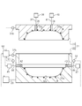
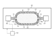
- the figure which shows the manufacturing apparatus of a high-pressure tank typically.
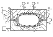
- molding die typically.
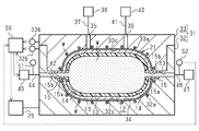
- the figure which shows the state which supplied the hot water to the liner typically.
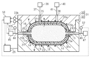
- the figure which shows the state which injected the thermosetting resin typically.
- a high-pressure tank 10 as a pressure container has a fiber-reinforced base in a fiber structure 21 having an elongated hollow liner 12 and a fiber-reinforced base material 19 covering the outside of the liner 12.
- the material 19 is formed by impregnating and hardening a matrix resin (shown by dot hatching).
- the high-pressure tank 10 reinforces the liner 12 with a fiber-reinforced composite material layer 11 made of a fiber-reinforced base material 19 impregnated and cured with a thermosetting resin as a matrix resin to secure the pressure resistance (mechanical strength) of the high-pressure tank 10. doing.
- the liner 12 is made of resin and has an elongated hollow shape.
- the direction in which the central axis L of the liner 12 extends is referred to as the axial direction Y.
- the liner 12 includes a cylindrical body portion 13.
- the center axis of the body portion 13 coincides with the center axis L of the liner 12.
- the liner 12 has dome portions 14 at both ends of the body portion 13 in the axial direction Y.
- the axial direction of the dome portion 14 matches the axial direction of the liner 12.
- Each dome portion 14 has a shape that becomes a dent as it goes toward the tip of each dome portion 14 along the axial direction Y of the liner 12.
- the direction orthogonal to the central axis L of the liner 12 is the radial direction X of the liner 12.
- the liner 12 includes a cap portion 15 on the tip side of each dome portion 14.
- Each base 15 is made of metal (for example, stainless steel).
- Each base portion 15 includes a connection portion 15a with the dome portion 14 and a hole portion 15b communicating with the space inside the liner 12.
- a valve (not shown) is attached to the hole portion 15b of the mouthpiece portion 15 on one end side of the liner 12 in the axial direction Y, and a screw (Fig. (Not shown) is screwed and closed.
- the outer surface of the connecting portion 15a of each base portion 15 is curved, and the outer surface of the connecting portion 15a constitutes a part of the outer surface of the dome portion 14.
- the fiber-reinforced base material 19 includes carbon fibers as reinforcing fibers in this embodiment.
- the reinforcing fiber is not limited to carbon fiber, and other fibers generally referred to as high elasticity and high strength such as glass fiber, silicon carbide ceramic fiber, aramid fiber and ultra high molecular weight polyethylene fiber may be used.
- the fiber-reinforced base material 19 has a structure in which a woven fabric 24 woven by plain weaving a plurality of warp yarns 22 and a plurality of weft yarns 23 is wound.
- the warp yarns 22 and the weft yarns 23 are arranged orthogonally to each other.
- the plurality of warp yarns 22 are arranged in the body portion 13 and each dome portion 14 in a state of being parallel to each other in the axial direction Y of the liner 12.
- the yarn main axis direction X1 of each warp yarn 22 extends linearly in the body portion 13 and the dome portion 14 in the circumferential direction Z of the liner 12.
- the plurality of weft yarns 23 are arranged in the body portion 13 and each dome portion 14 in parallel with each other in the circumferential direction Z of the liner 12.
- the warp yarns 22 and the weft yarns 23 are arranged orthogonally to each other, and the warp yarns 22 are reinforced in the radial direction X by aligning the extending direction of the warp yarns 22 in the yarn main axis direction X1 with the circumferential direction Z of the liner 12.
- the liner 12 is reinforced in the axial direction Y by the weft 23.
- the manufacturing apparatus of the high-pressure tank 10 includes a molding die 31 for manufacturing the high-pressure tank 10 by closed molding.
- the molding die 31 is composed of a lower die 32 and an upper die 33.
- the molding die 31 includes a cavity 34 corresponding to the shape of the high-pressure tank 10 to be formed in the mold closed state.
- the cavity 34 is formed by combining a lower mold recess 32c provided in the lower mold 32 and an upper mold recess 33c provided in the upper mold 33.
- the lower die 32 is provided with a heat medium passage 32a, and the plurality of heat medium passages 32a of the lower die 32 are provided along the lower surface of the lower die recess 32c.
- a heat medium passage 33a is provided in the upper die 33, and a plurality of heat medium passages 33a of the upper die 33 are provided along the upper surface of the upper die recess 33c.
- the lower die 32 is provided with a lower die temperature sensor 32b that measures the temperature of the lower die 32, and the upper die 33 is provided with an upper die temperature sensor 33b that measures the temperature of the upper die 33.
- Heat-controlled water is supplied from the heat medium supply device 29 to the heat medium passages 32a and 33a as a heat medium.
- the hot water W supplied from the heat medium supply device 29 flows through the heat medium passages 32a and 33a, and the temperature of the lower mold 32 and the upper mold 33 is adjusted by heat exchange with the hot water W.
- the lower mold 32 and the upper mold 33 are heated by heat exchange with the hot water W.
- the fiber-reinforced base material 19 is heated from the outer surface side by the heated lower mold 32 and upper mold 33.
- An injection hole 35 and a discharge hole 36, which communicate with the cavity 34 in the mold closed state, are formed in the upper mold 33.
- the injection hole 35 has one end formed at a position corresponding to the cavity 34, and the other end connected to a resin injection device 38 via an injection pipe 37.
- a known device is used as the resin injection device 38, and is configured to pump out the thermosetting resin stored in the tank toward the cavity 34.
- the discharge hole 36 has one end formed at a position corresponding to the cavity 34, and the other end connected to the decompression pump 40 via the suction pipe 41.
- the lower mold 32 is formed with an inflow path 42 and an outflow path 43 which communicate with the cavity 34 in the mold closed state.
- the inflow path 42 and the outflow path 43 are provided at positions facing each other across the cavity 34.
- the inflow path 42, the cavity 34, and the outflow path 43 are a continuous space.
- the inflow path 42 and the outflow path 43 penetrate the lower mold 32 so as to communicate with the lower mold recess 32c of the lower mold 32.
- the inflow passage 42 has one end formed at a position corresponding to the cavity 34, and the other end connected to the fluid supply device 45 via the first pipe 44.
- the fluid supply device 45 supplies the hot water W as a fluid to the inside of the liner 12 and adjusts the temperature of the hot water W to be supplied.
- the manufacturing apparatus of the high-pressure tank 10 includes a first temperature sensor S1 that measures the temperature of the hot water W flowing through the first pipe 44.
- the outflow passage 43 has one end formed at a position corresponding to the cavity 34, and the other end connected to the fluid discharge tank 47 through the second pipe 46.
- the hot water W discharged from the molding die 31 flows into the fluid discharge tank 47 via the outflow passage 43.
- the manufacturing apparatus of the high-pressure tank 10 includes a second temperature sensor S2 that measures the temperature of the hot water W flowing through the second pipe 46.
- the manufacturing apparatus of the high-pressure tank 10 includes a temperature control unit 50 that is signal-connected to the lower mold temperature sensor 32b, the upper mold temperature sensor 33b, the first temperature sensor S1, and the second temperature sensor S2.
- the measured values of the lower mold temperature sensor 32b, the upper mold temperature sensor 33b, the first temperature sensor S1, and the second temperature sensor S2 are input to the temperature control unit 50.
- the temperature control unit 50 is signal-connected to the fluid supply device 45 and the heat medium supply device 29.
- the temperature control unit 50 controls the fluid supply device 45 based on the measured values of the first temperature sensor S1 and the second temperature sensor S2, and adjusts the temperature of the hot water W supplied to the inside of the liner 12. Further, the temperature control unit 50 controls the heat medium supply device 29 based on the measured values of the lower mold temperature sensor 32b and the upper mold temperature sensor 33b to adjust the temperature of the hot water W supplied to the heat medium passages 32a and 33a. To do.
- the manufacturing method of the high-pressure tank 10 includes an arrangement step of arranging the fiber structure 21 in the cavity 34, an impregnation step for impregnating the fiber-reinforced base material 19 with a thermosetting resin before thermosetting, and a heat treatment before thermosetting.
- a thermosetting step of thermosetting the curable resin includes a cooling step of cooling the high-pressure tank 10 manufactured by thermosetting a thermosetting resin, and a step of taking out the high-pressure tank 10 from the cavity 34.
- the fiber structure 21 is placed inside the cavity 34 (inside the molding die 31).
- the fiber structure 21 is arranged in the lower mold recess 32c of the lower mold 32, and the mouthpiece portions 15 at both ends in the axial direction Y are supported by the lower mold recess 32c.
- the inflow passage 42 communicates with the hole 15b of the mouthpiece portion 15 on the one end side in the axial direction Y of the liner 12, and the fluid supply device 45 is connected via the inflow passage 42 and the first pipe 44.
- the outflow passage 43 communicates with the hole 15b of the mouthpiece portion 15 on the other end side of the liner 12 in the axial direction Y, and the fluid discharge tank 47 is connected via the outflow passage 43 and the second pipe 46.
- the upper mold 33 comes into contact with the lower mold 32, and the mold is closed until the hermeticity of the cavity 34 is secured. Then, the cavity 34 is defined by the lower mold recess 32 c and the upper mold recess 33 c, and the fiber structure 21 is arranged in the cavity 34. Further, the inner surface of the lower mold recess 32c and the inner surface of the upper mold recess 33c are close to the fiber reinforced base material 19 of the fiber structure 21 in the cavity 34.
- the hot water W whose temperature has been adjusted by the temperature control unit 50 is supplied from the heat medium supply device 29 to the heat medium passages 32a and 33a to generate heat medium.
- the lower mold 32 and the upper mold 33 are heated (temperature control) by heat exchange with the hot water W flowing through the passages 32a and 33a.
- the temperature control unit 50 adjusts the temperature of the hot water W supplied to the heat medium passages 32a and 33a so that the temperatures of the lower mold 32 and the upper mold 33 become desired temperatures.
- the temperature control unit 50 sets the temperature of the lower die 32 measured by the lower die temperature sensor 32b and the temperature of the upper die 33 measured by the upper die temperature sensor 33b to 80 to 150° C. The temperature of the hot water W supplied to the heat medium passages 32a and 33a is adjusted.
- the temperature control unit 50 controls the temperature of the lower mold 32 and the upper mold 33 to be higher than the heat resistant temperature of the liner 12.
- the temperature of the hot water W flowing through the heat medium passages 32a and 33a is adjusted so as to be lowered.
- the temperature control unit 50 adjusts the temperatures of the lower mold 32 and the upper mold 33.
- the hot water W is supplied from the fluid supply device 45 into the liner 12 in the cavity 34.
- the hot water W is supplied to the inside of the liner 12 in order to suppress the expansion of the liner 12 when the inside of the cavity 34 is depressurized in the subsequent process.
- the temperature control unit 50 controls the fluid supply device 45 so that the temperature of the hot water W supplied from the fluid supply device 45 becomes a temperature suitable for the impregnation step which is the post-step.
- the temperature control unit 50 based on the temperature of the hot water W acquired from the first temperature sensor S1 and the second temperature sensor S2, sets the temperature of the hot water W to be supplied to the inside of the liner 12 in the subsequent step of impregnation. Adjust so that the temperature is suitable for the process.
- the temperature control unit 50 estimates the temperature of the liner 12 from the difference between the temperature of the hot water W before being supplied to the inside of the liner 12 and the temperature of the hot water W discharged from the liner 12, and supplies the temperature to the inside of the liner 12.
- the temperature of the hot water W to be used is determined.
- the temperature suitable for the impregnation step is a temperature at which the thermosetting resin before being thermoset can be prevented from cooling and increasing in viscosity.
- the temperature of the hot water W at this time is 80 to 150° C. in this embodiment.
- the decompression pump 40 is driven to decompress the inside of the cavity 34 to a state close to vacuum via the discharge hole 36. At this time, the hot water W supplied to the liner 12 prevents the liner 12 from expanding.
- thermosetting resin 57 before thermosetting is injected from the injection hole 35 into the cavity 34 from the resin injecting device 38 while the inside of the cavity 34 is depressurized.
- the resin injecting device 38 sends out the thermosetting resin 57 so that the thermosetting resin 57 sent out has a constant flow rate.
- the thermosetting resin 57 injected into the cavity 34 before the thermosetting is filled in the gap between the periphery of the fiber reinforced base material 19 and the inner surface of the cavity 34, and the thermosetting resin 57 is filled in the cavity 34. Is gradually filled from the bottom.
- thermosetting resin 57 When the thermosetting resin 57 is injected into the cavity 34, the liner 12 is pressurized by the injected thermosetting resin 57, but the hot water W supplied to the inside of the liner 12 causes the liner 12 to move. Since pressure is applied from the inside, contraction of the liner 12 is suppressed.
- thermosetting resin 57 before thermosetting is heated from the liner 12 side by the hot water W supplied into the liner 12, and the heated lower mold 32 and upper mold 33 cause thermosetting.
- the resin 57 is heated from the lower mold 32 and upper mold 33 sides. Therefore, the thermosetting resin 57 before thermosetting impregnates the fiber reinforced base material 19 in a state of being heated from both the liner 12 side and the molding die 31 side.
- thermosetting resin 57 is continuously injected into the cavity 34, and the thermosetting resin 57 is injected into the cavity 34 until the entire fibrous structure 21 in the cavity 34 is covered with the thermosetting resin 57. After that, the operation of the resin injection device 38 and the decompression pump 40 is stopped. After that, the mold is further closed, and the gap between the lower mold 32 and the upper mold 33 is narrowed. Then, the thermosetting resin 57 is extruded toward the fiber-reinforced base material 19, and a gap is prevented from being formed between the inner surface of the cavity 34 and the layer of the thermosetting resin 57.
- the temperature control unit controls the temperature of the hot water W supplied from the fluid supply device 45 into the liner 12 to a temperature suitable for thermosetting the thermosetting resin 57.
- 50 controls the fluid supply device 45. Specifically, the temperature control unit 50 estimates the temperature of the liner 12 from the difference between the temperature of the hot water W before being supplied to the inside of the liner 12 and the temperature of the hot water W discharged from the liner 12, The temperature of the hot water W supplied to the inside of the liner 12 is determined.
- the temperature suitable for thermosetting is a temperature at which the thermosetting of the thermosetting resin 57 is accelerated.
- the temperature control unit 50 controls the heat medium supply device 29 so that the temperature of the hot water W flowing through the heat medium passages 32a and 33a also becomes a temperature suitable for promoting the heat curing of the thermosetting resin 57. .. Specifically, the temperature control unit 50, based on the temperatures of the lower mold 32 and the upper mold 33 acquired from the lower mold temperature sensor 32b and the upper mold temperature sensor 33b, the temperature of the hot water W flowing in the heat medium passages 32a and 33a. The lower mold 32 and the upper mold 33 are adjusted to a temperature at which the thermosetting of the thermosetting resin 57 is accelerated.
- the temperature control unit 50 controls the temperature of the hot water W supplied to the inside of the liner 12. , Higher than the heating temperature of the lower mold 32 and the upper mold 33. For example, the temperature control unit 50 adjusts the temperature of the hot water W supplied to the inside of the liner 12 to 100° C., and adjusts the temperatures of the lower mold 32 and the upper mold 33 to 80° C.
- the temperature difference between the hot water W supplied to the inside of the liner 12 and the heated lower mold 32 and upper mold 33 is preferably 5 to 20° C. Then, when the temperature difference between the hot water W supplied to the inside of the liner 12 and the lower mold 32 and the upper mold 33 becomes 5° C. or more, the thermosetting resin 57 is heated by the liner 12 so that the fiber reinforced base material 19 is heated. The inner surface side is thermally cured before the outer surface. After that, the entire thermosetting resin 57 with which the fiber reinforced base material 19 is impregnated is thermally cured by heating from the liner 12 and heating from the molding die 31.
- the fiber-reinforced composite material layer 11 formed by thermosetting the thermosetting resin 57 is formed such that the inner surface of the fiber-reinforced composite material layer 11 is in contact with the outer surface of the liner 12, and the fiber-reinforced composite material is formed.
- the liner 12 is reinforced by the layer 11.
- a cooling process for cooling the high-pressure tank 10 is performed.
- the temperature of the hot water W supplied to the inside of the liner 12 is adjusted to a temperature suitable for removing the high-pressure tank 10 from the molding die 31 by controlling the fluid supply device 45 by the temperature control unit 50.
- the temperature control unit 50 determines the temperature of the hot water W in the liner 12 as a temperature suitable for the cooling process based on the temperatures of the hot water W acquired from the first temperature sensor S1 and the second temperature sensor S2. Adjust so that For example, the temperature control unit 50 adjusts the temperature of the hot water W supplied to the inside of the liner 12 to 30 to 80°C.
- the temperature of the hot water W supplied to the inside of the liner 12 is adjusted to be lower than the temperatures of the lower die 32 and the upper die 33.
- the temperature control unit 50 does not change the temperature of the hot water W supplied to the heat medium passages 32a and 33a, and the temperatures of the lower mold 32 and the upper mold 33 are the same as in the impregnation process. Therefore, since the temperature of the lower mold 32 and the upper mold 33 is 80 to 150° C., when the temperature of the lower mold 32 and the upper mold 33 is 80° C., the temperature control unit 50 is installed inside the liner 12 in the cooling process. The temperature of the supplied hot water W is adjusted to be lower than 80°C.
- the liner 12 is cooled from the inner surface side, and the high pressure tank 10 is cooled. After that, in the take-out step, the molding die 31 is opened, and the high-pressure tank 10 is taken out of the molding die 31. According to the above embodiment, the following operational effects can be obtained.
- thermosetting process the temperature of the hot water W supplied from the fluid supply device 45 into the liner 12 is set by the temperature control unit 50 to be lower than the heating temperature of the thermosetting resin 57 by the lower mold 32 and the upper mold 33. Is also adjusted to be higher. Therefore, the thermosetting resin 57 impregnated in the fiber-reinforced base material 19 is thermoset on the inner surface side before the outer surface side. Then, in the manufactured fiber reinforced composite material layer 11, it is possible to suppress the formation of curing strain on the inner surface side, and between the inner surface of the manufactured fiber reinforced composite material layer 11 and the outer surface of the liner 12. It is possible to suppress the formation of the gap.
- the reinforcing performance of the fiber-reinforced composite material layer 11 can be exhibited, the load when the liner 12 receives the internal pressure can be suitably received by the fiber-reinforced composite material layer 11, and the strength of the high-pressure tank 10 can be increased. The decrease can be suppressed.
- the temperature control unit 50 adjusts the temperature of the hot water W supplied to the inside of the liner 12 so that the temperature is suitable for impregnating the fiber-reinforced base material 19 with the thermosetting resin 57. To do. For this reason, it is possible to prevent the fiber-reinforced base material 19 from cooling and increasing in viscosity while impregnating the fiber-reinforced base material 19 and impeding impregnation into the fiber-reinforced base material 19. The time required for impregnation can be shortened.
- the temperature control unit 50 adjusts the temperature of the hot water W supplied to the inside of the liner 12 so that the high pressure tank 10 can be taken out from the molding die 31. To do. Therefore, for example, as compared with the case where the high pressure tank 10 is naturally cooled, the time required to take out the high pressure tank 10 from the molding die 31 can be shortened. Therefore, the cooling step can shorten the time required for producing the high-pressure tank 10 and improve the productivity of the high-pressure tank 10.
- the lower mold 32 and the upper mold 33 are heated by heat exchange with the hot water W flowing through the heat medium passages 32a and 33a. Since the fiber-reinforced base material 19 of the fiber structure 21 arranged in the cavity 34 is in a state close to the inner surface of the cavity 34, the heat of the molding die 31 is impregnated in the fiber-reinforced base material 19 to make it thermosetting.
- the thermosetting resin 57 is easily transferred to the resin 57, and the thermosetting resin 57 is also efficiently heated from the outer surface side of the liner 12.
- thermosetting of the thermosetting resin 57 is promoted from both sides of the liner 12 side and the molding die 31 side, and the thermosetting resin 57 is heated more than the case where it is heated only from the molding die 31 side, for example.
- the productivity required for the high-pressure tank 10 can be improved by shortening the time required for curing and shortening the time required for producing the high-pressure tank 10.
- the high pressure tank 10 is manufactured by the RTM method using the molding die 31.
- the thermosetting resin 57 can be heated from the outer surface side.
- the thermosetting resin 57 can be efficiently heated in the molding die 31, and the thermosetting resin 57 that is easily thermoset is used. it can.
- the time required for curing the thermosetting resin 57 can be shortened, the time required for the production of the high pressure tank 10 can be shortened, and the productivity of the high pressure tank 10 can be improved.
- thermosetting resin 57 Before supplying the thermosetting resin 57 to the cavity 34, the cavity 34 is depressurized.
- a fluid hot water W
- a fluid hot water W
- the thermosetting resin 57 is injected into the cavity 34, in order to suppress the contraction of the liner 12 due to the pressure applied by the injected thermosetting resin 57, a fluid (hot water W) is contained in the liner 12. Is supplied. Then, by adjusting the temperature of the hot water W supplied into the liner 12 by the temperature control unit 50, the time required for the impregnation step, the thermosetting step, and the cooling step can be shortened. Therefore, by using the hot water W supplied to the liner 12, expansion and contraction of the liner 12 can be suppressed and productivity can be improved.
- the high pressure tank 10 may be manufactured by an open mold instead of the closed mold RTM method.
- a reinforcing fiber impregnated with a thermosetting resin is wound around the outside of the liner 12 by a filament winding method to form a fiber-reinforced base material 19 covering the outside of the liner 12.
- the liner 12 covered with the fiber-reinforced base material 19, that is, the fiber structure 21 is placed in the oven 60 as a heating device, and the placement step is performed.
- a fluid supply device 45 and a fluid discharge tank 47 are arranged in the oven 60, and the fluid can be supplied from the fluid supply device 45 to the liner 12.
- the fluid is supplied from the fluid supply device 45 to the liner 12 in the oven 60.
- the temperature control unit 50 controls the temperatures of the fluid supply device 45 and the oven 60 so that the temperature of the fluid supplied from the fluid supply device 45 becomes a temperature suitable for the thermosetting process.
- the temperature of the hot water W supplied from the fluid supply device 45 into the liner 12 is adjusted by the temperature control unit 50 to be higher than the heating temperature of the thermosetting resin 57 by the oven 60.
- the heating temperature of the oven 60 is adjusted to 80 to 160° C.
- the temperature of the hot water W supplied to the inside of the liner 12 is adjusted to be higher than the heating temperature of the oven 60 within the range of 80 to 160° C. To do.
- thermosetting resin 57 impregnated in the fiber-reinforced base material 19 is thermoset on the inner surface side before on the outer surface side. Then, in the manufactured fiber reinforced composite material layer 11, it is possible to suppress the formation of curing strain on the inner surface side, and between the inner surface of the manufactured fiber reinforced composite material layer 11 and the outer surface of the liner 12. It is possible to suppress the formation of the gap. Therefore, the fiber-reinforced composite material layer 11 can receive the load when the liner 12 receives the internal pressure, and can suppress the strength reduction of the high-pressure tank 10. As a result, in order to increase the strength of the high-pressure tank 10, it is not necessary to thicken the fiber-reinforced base material 19 or increase the amount of the thermosetting resin 57, and it is possible to reduce the weight of the high-pressure tank 10.
- the temperature control unit 50 adjusts the temperature of the hot water W supplied to the inside of the liner 12 within a range of 30 to 80° C., for example, so that the high pressure tank 10 can be taken out of the oven 60. Therefore, for example, the time required to take out the high-pressure tank 10 from the oven 60 can be shortened as compared with the case where the high-pressure tank 10 is naturally cooled.
- the cooling step may be performed by natural cooling without supplying the hot water W into the liner 12.
- cooling by the lower mold 32 and the upper mold 33 cooled by adjusting the temperature of the hot water W flowing in the heat medium passages 32a and 33a may be performed. ..
- the hot water W may not be supplied to the inside of the liner 12, and the impregnation of the thermosetting resin 57 may be promoted only by heating with the lower mold 32 and the upper mold 33.
- the hot water W is supplied to the inside of the liner 12 to accelerate the impregnation of the thermosetting resin 57 only by heating from the inner surface side of the fiber reinforced base material 19, and the heat generated by the lower mold 32 and the upper mold 33 is increased.
- the heating of the curable resin 57 may be omitted.
- the fluid supplied from the fluid supply device 45 to the liner 12 may be steam, oil, or an incompressible fluid.
- the fluid supplied from the heat medium supply device 29 to the heat medium passage 32a of the lower die 32 and the heat medium passage 33a of the upper die 33 may be steam, oil, or an incompressible fluid.
- the heating of the lower mold 32 and the upper mold 33 may be performed by a method other than heating with a fluid.
- the lower mold 32 and the upper mold 33 can be heated by heating with a heater as a heating device arranged outside the lower mold 32 and the upper mold 33, or by sending hot air with a hot air blower as the heating device. It may be.
- the liner 12 may be softened by heat generated by the resin when the thermosetting resin 57 is cured.
- the temperature of the fluid supplied to the liner 12 may be lowered (for example, 30 to 80° C.) and the liner 12 may be cooled before the softening of the liner 12 occurs.
- the temperature of the fluid supplied to the liner 12 is adjusted based on the measurement values of the first temperature sensor S1 and the second temperature sensor S2, but may be adjusted to the temperature stored in the temperature control unit 50 in advance. ..
- each of the heat medium supply device 29 and the fluid supply device 45 may have a temperature control unit. ..
- the temperature control unit of the heat medium supply device 29 adjusts the temperature of the hot water W supplied to the heat medium passages 32a and 33a, and the temperature control unit of the fluid supply device 45 supplies the hot water W to the inside of the liner 12. Temperature is adjusted.
- reinforced fibers are wound without being impregnated with a thermosetting resin to form a fiber reinforced base material 19 to form a fiber structure 21.
- the body 21 may be impregnated and cured with the thermosetting resin 57 by the RTM method to form the high-pressure tank 10.
- the high-pressure tank 10 is not limited to being mounted and used as a hydrogen source of an electric vehicle equipped with a fuel cell, and may be applied to, for example, a hydrogen source of a hydrogen engine or a heat pump. It may also be used as a hydrogen source for a fuel cell of a household power source.
- the pressure container is not limited to a high-pressure tank that stores hydrogen, but may be applied to a pressure container that stores other gases such as nitrogen and compressed natural gas.
- the liner 12 is not limited to resin, and may be metal.
Landscapes
- Engineering & Computer Science (AREA)
- Mechanical Engineering (AREA)
- Chemical & Material Sciences (AREA)
- Composite Materials (AREA)
- General Engineering & Computer Science (AREA)
- Physics & Mathematics (AREA)
- Health & Medical Sciences (AREA)
- Oral & Maxillofacial Surgery (AREA)
- Thermal Sciences (AREA)
- Moulding By Coating Moulds (AREA)
- Filling Or Discharging Of Gas Storage Vessels (AREA)
- Pressure Vessels And Lids Thereof (AREA)
Priority Applications (3)
| Application Number | Priority Date | Filing Date | Title |
|---|---|---|---|
| CN202080013368.5A CN113423978A (zh) | 2019-02-13 | 2020-01-16 | 压力容器的制造方法以及压力容器的制造装置 |
| US17/429,778 US20220134606A1 (en) | 2019-02-13 | 2020-01-16 | Method for manufacturing pressure container and manufacturing apparatus for the pressure container |
| EP20756436.0A EP3926217A4 (en) | 2019-02-13 | 2020-01-16 | PRESSURE VESSEL PRODUCTION METHOD AND PRESSURE VESSEL PRODUCTION DEVICE |
Applications Claiming Priority (2)
| Application Number | Priority Date | Filing Date | Title |
|---|---|---|---|
| JP2019023772A JP7059963B2 (ja) | 2019-02-13 | 2019-02-13 | 圧力容器の製造方法及び圧力容器の製造装置 |
| JP2019-023772 | 2019-02-13 |
Publications (1)
| Publication Number | Publication Date |
|---|---|
| WO2020166265A1 true WO2020166265A1 (ja) | 2020-08-20 |
Family
ID=72045326
Family Applications (1)
| Application Number | Title | Priority Date | Filing Date |
|---|---|---|---|
| PCT/JP2020/001214 Ceased WO2020166265A1 (ja) | 2019-02-13 | 2020-01-16 | 圧力容器の製造方法及び圧力容器の製造装置 |
Country Status (5)
| Country | Link |
|---|---|
| US (1) | US20220134606A1 (enExample) |
| EP (1) | EP3926217A4 (enExample) |
| JP (1) | JP7059963B2 (enExample) |
| CN (1) | CN113423978A (enExample) |
| WO (1) | WO2020166265A1 (enExample) |
Cited By (2)
| Publication number | Priority date | Publication date | Assignee | Title |
|---|---|---|---|---|
| CN115071169A (zh) * | 2021-03-16 | 2022-09-20 | 丰田自动车株式会社 | 制造高压罐的方法、高压罐制造设备及非暂时性存储介质 |
| PL445706A1 (pl) * | 2023-07-28 | 2025-02-03 | Sunex Spółka Akcyjna | Kompozytowy zbiornik kombinowany i sposób wytwarzania kompozytowych zbiorników kombinowanych |
Families Citing this family (4)
| Publication number | Priority date | Publication date | Assignee | Title |
|---|---|---|---|---|
| JP7283435B2 (ja) * | 2020-04-27 | 2023-05-30 | トヨタ自動車株式会社 | 高圧タンクの製造方法、高圧タンク |
| WO2023079823A1 (ja) | 2021-11-05 | 2023-05-11 | 三菱瓦斯化学株式会社 | ライナー、および、圧力容器 |
| JP2023112249A (ja) * | 2022-02-01 | 2023-08-14 | トヨタ自動車株式会社 | 繊維層の加工方法および高圧タンクの製造方法 |
| JP7661942B2 (ja) * | 2022-08-01 | 2025-04-15 | トヨタ自動車株式会社 | 高圧タンクの製造方法 |
Citations (5)
| Publication number | Priority date | Publication date | Assignee | Title |
|---|---|---|---|---|
| JP2013209510A (ja) | 2012-03-30 | 2013-10-10 | Dainippon Toryo Co Ltd | 繊維強化樹脂成形体被覆組成物、該被覆組成物を塗装して得られる繊維強化樹脂成形体及び該繊維強化樹脂成形体の製造方法 |
| JP2015059123A (ja) | 2013-09-17 | 2015-03-30 | トヨタ自動車株式会社 | エポキシ樹脂と高圧ガスタンクの製造方法 |
| JP2015113864A (ja) * | 2013-12-09 | 2015-06-22 | Jx日鉱日石エネルギー株式会社 | 複合容器の製造システム、及び複合容器の製造方法 |
| JP2017043045A (ja) * | 2015-08-28 | 2017-03-02 | トヨタ自動車株式会社 | 高圧ガスタンクの製造方法 |
| JP2018187775A (ja) * | 2017-04-28 | 2018-11-29 | トヨタ自動車株式会社 | 高圧タンクの製造方法 |
Family Cites Families (13)
| Publication number | Priority date | Publication date | Assignee | Title |
|---|---|---|---|---|
| US3137898A (en) * | 1960-09-19 | 1964-06-23 | Structural Fibers | Apparatus for the manufacture of fiberreinforced plastic tanks |
| US3177105A (en) * | 1960-10-17 | 1965-04-06 | Structural Fibers | Method of making fiber-reinforced hollow article |
| US3937781A (en) * | 1971-05-20 | 1976-02-10 | Structural Fibers, Inc. | Method for forming fiber-reinforced plastic articles |
| US4470860A (en) * | 1982-01-07 | 1984-09-11 | Hercules Incorporated | Fabricating large, thick wall, tubular structures |
| FR2740382B1 (fr) * | 1995-10-25 | 1997-12-05 | Snecma | Procede de moulage de pieces allongees a haute resistance en composite fibre-resine |
| US6565793B1 (en) * | 1998-09-11 | 2003-05-20 | Essef Corporation | Method for fabricating composite pressure vessels |
| US6171423B1 (en) * | 1998-09-11 | 2001-01-09 | Essef Corporation | Method for fabricating composite pressure vessels |
| US6660214B2 (en) * | 2001-02-23 | 2003-12-09 | Essef Corporation | Pressure vessel manufacture method |
| JP2005337394A (ja) * | 2004-05-27 | 2005-12-08 | Nippon Oil Corp | 繊維強化圧力容器及びその製造法 |
| US8858857B2 (en) * | 2007-03-12 | 2014-10-14 | Geoffrey Michael Wood | Process for the rapid fabrication of composite gas cylinders and related shapes |
| WO2011154994A1 (ja) * | 2010-06-08 | 2011-12-15 | トヨタ自動車株式会社 | 高圧タンクおよび高圧タンクの製造方法 |
| JP5531040B2 (ja) * | 2012-02-27 | 2014-06-25 | トヨタ自動車株式会社 | 高圧ガスタンクの製造方法 |
| JP2018146001A (ja) * | 2017-03-03 | 2018-09-20 | トヨタ自動車株式会社 | 高圧タンク |
-
2019
- 2019-02-13 JP JP2019023772A patent/JP7059963B2/ja active Active
-
2020
- 2020-01-16 CN CN202080013368.5A patent/CN113423978A/zh active Pending
- 2020-01-16 EP EP20756436.0A patent/EP3926217A4/en not_active Withdrawn
- 2020-01-16 US US17/429,778 patent/US20220134606A1/en not_active Abandoned
- 2020-01-16 WO PCT/JP2020/001214 patent/WO2020166265A1/ja not_active Ceased
Patent Citations (5)
| Publication number | Priority date | Publication date | Assignee | Title |
|---|---|---|---|---|
| JP2013209510A (ja) | 2012-03-30 | 2013-10-10 | Dainippon Toryo Co Ltd | 繊維強化樹脂成形体被覆組成物、該被覆組成物を塗装して得られる繊維強化樹脂成形体及び該繊維強化樹脂成形体の製造方法 |
| JP2015059123A (ja) | 2013-09-17 | 2015-03-30 | トヨタ自動車株式会社 | エポキシ樹脂と高圧ガスタンクの製造方法 |
| JP2015113864A (ja) * | 2013-12-09 | 2015-06-22 | Jx日鉱日石エネルギー株式会社 | 複合容器の製造システム、及び複合容器の製造方法 |
| JP2017043045A (ja) * | 2015-08-28 | 2017-03-02 | トヨタ自動車株式会社 | 高圧ガスタンクの製造方法 |
| JP2018187775A (ja) * | 2017-04-28 | 2018-11-29 | トヨタ自動車株式会社 | 高圧タンクの製造方法 |
Non-Patent Citations (1)
| Title |
|---|
| See also references of EP3926217A4 |
Cited By (4)
| Publication number | Priority date | Publication date | Assignee | Title |
|---|---|---|---|---|
| CN115071169A (zh) * | 2021-03-16 | 2022-09-20 | 丰田自动车株式会社 | 制造高压罐的方法、高压罐制造设备及非暂时性存储介质 |
| EP4059701A1 (en) * | 2021-03-16 | 2022-09-21 | Toyota Jidosha Kabushiki Kaisha | Method for manufacturing high-pressure tank, high-pressure tank manufacturing apparatus, and non-transitory storage medium |
| CN115071169B (zh) * | 2021-03-16 | 2024-05-31 | 丰田自动车株式会社 | 制造高压罐的方法、高压罐制造设备及非暂时性存储介质 |
| PL445706A1 (pl) * | 2023-07-28 | 2025-02-03 | Sunex Spółka Akcyjna | Kompozytowy zbiornik kombinowany i sposób wytwarzania kompozytowych zbiorników kombinowanych |
Also Published As
| Publication number | Publication date |
|---|---|
| CN113423978A (zh) | 2021-09-21 |
| JP2020133666A (ja) | 2020-08-31 |
| EP3926217A1 (en) | 2021-12-22 |
| US20220134606A1 (en) | 2022-05-05 |
| EP3926217A4 (en) | 2022-04-13 |
| JP7059963B2 (ja) | 2022-04-26 |
Similar Documents
| Publication | Publication Date | Title |
|---|---|---|
| WO2020166265A1 (ja) | 圧力容器の製造方法及び圧力容器の製造装置 | |
| CN109955494B (zh) | 高压罐和制造高压罐的方法 | |
| CN113492539B (zh) | 中空成形品的成形系统及中空成形品的成形方法 | |
| KR101955603B1 (ko) | 고압 가스 탱크의 제조 방법 | |
| JP6215678B2 (ja) | 複合容器の製造システム、及び複合容器の製造方法 | |
| JP6240841B2 (ja) | 複合容器の製造システム、及び複合容器の製造方法 | |
| JP2019142118A (ja) | 高圧タンクの製造方法 | |
| US20200376716A1 (en) | Method of fabricating both a woven fiber preform and a composite material part | |
| WO2020026811A1 (ja) | 圧力容器及び圧力容器の製造方法 | |
| JP2020133666A5 (enExample) | ||
| CN115379946A (zh) | 用于由复合材料制成的涡轮机部件的预制件的制造方法和相应部件 | |
| US20210323250A1 (en) | Method for shaping a fibrous preform by compacting in order to produce a composite material part | |
| JP6337398B2 (ja) | 複合容器の製造方法、及び複合容器 | |
| JP2017096334A (ja) | 高圧タンクの製造方法 | |
| CN112497721A (zh) | 罐的制造方法 | |
| KR102629780B1 (ko) | 고무 및 복합소재를 이용한 압력용기 제조방법 | |
| JP2017217787A (ja) | ガスタンクの製造方法 | |
| CN108139024B (zh) | 配有连续纤维的压力容器 | |
| JP2011230398A (ja) | 高圧ガスタンクの製造方法と製造装置 | |
| KR102640757B1 (ko) | 압력용기 성형용 맨드릴의 유체 순환 시스템 | |
| JP7683573B2 (ja) | 高圧タンク用金型構造 | |
| JP2018012235A (ja) | タンクの製造方法 | |
| JP2021167656A (ja) | タンクの製造方法 | |
| US11027480B2 (en) | Method for manufacturing high-pressure tank | |
| US20230332743A1 (en) | Tank and manufacturing method for tank |
Legal Events
| Date | Code | Title | Description |
|---|---|---|---|
| 121 | Ep: the epo has been informed by wipo that ep was designated in this application |
Ref document number: 20756436 Country of ref document: EP Kind code of ref document: A1 |
|
| NENP | Non-entry into the national phase |
Ref country code: DE |
|
| ENP | Entry into the national phase |
Ref document number: 2020756436 Country of ref document: EP Effective date: 20210913 |